Technical Manual
Version number: EN-V9-01
Thank you for choosing Coiliiot products.
To ensure optimal use of this product, please read the following instructions before use.
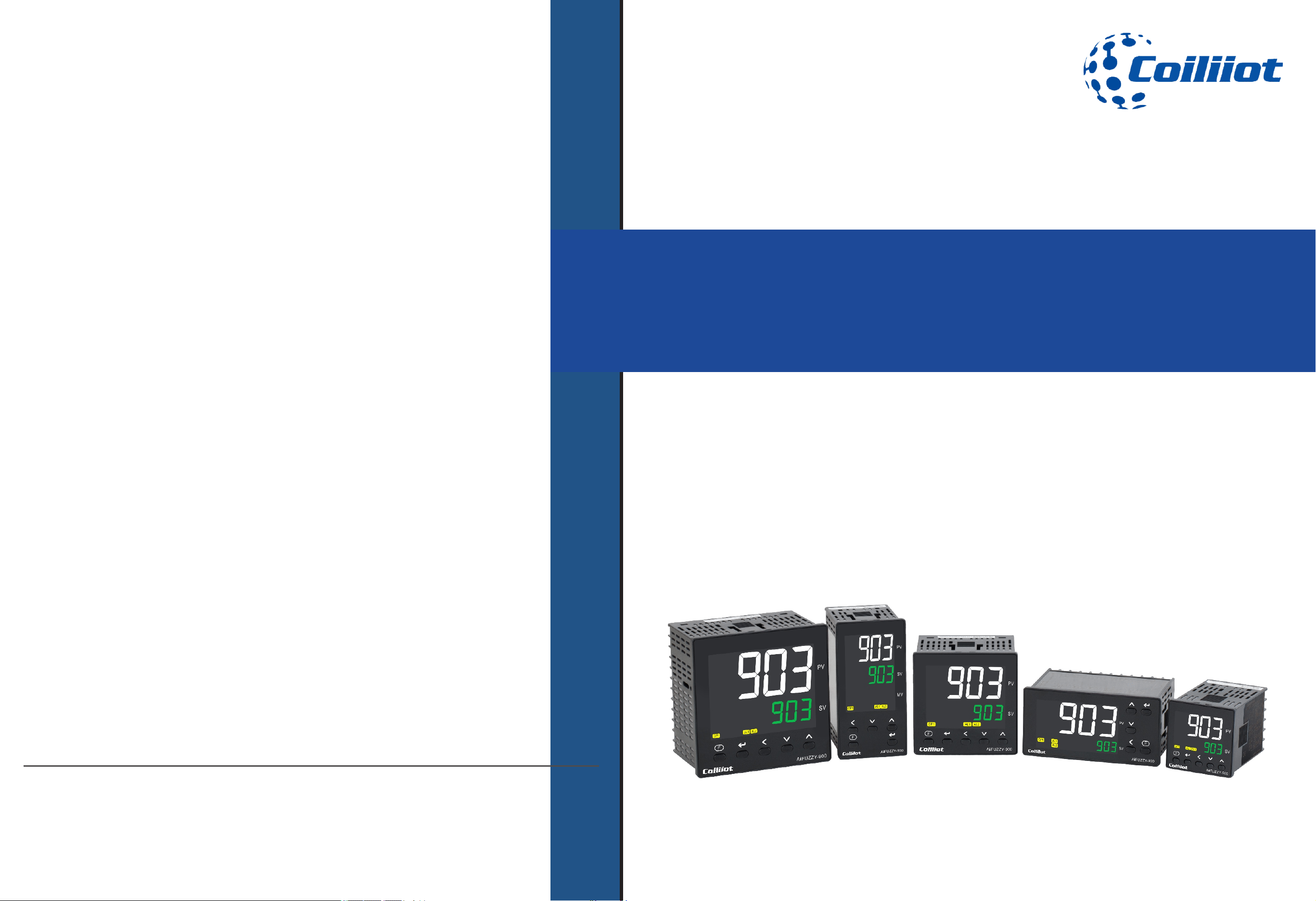
Economical PID Temperature Controller
For General Use
AiFUZZY-903
Contact Us
Coiliiot LLC
8 THE GRN STE B,
Dover, DE, 19901
(+1)857-565-5912
info@coiliiot.com
https://coiliiot.com
Safety Instructions
■Safety Instructions
Page 1/19 pages in total A FUZZY-903 : 9- i Technical Manual_Version number EN-V 01
Attention
Do not touch the terminals while the power is on, as this may result in minor
injuries from electric shock.
Do not allow metal objects, conductors, debris (such as installation cuttings), moisture,
or other foreign matter to enter the digital controller, setup tool ports, or the pins on the
Setup Tool cable connectors.
Failure to do so may result in electric shock, short circuits, or malfunction of the
equipment.
Do not disassemble, modify, or repair the product, or touch any internal components.
Failure to follow this may result in electric shock, fire, or equipment failure.
If the output relays are used beyond their life expectancy, contact welding or burning
may occur.
Always ensure the application conditions are considered, and use the output relays
within their rated load and electrical life expectancy.
The life span of the output relays can vary significantly depending on the load and
switching conditions.
Do not use the product in environments exposed to flammable or explosive gases,
as this may lead to injury due to explosion.
This equipment is an open processing controller. Do not use it in a control cabinet where
a fire hazard may exist.
When using more than two open-circuit switches, ensure all switches are turned off
before performing maintenance or inspections to keep the product powered off.

Chapter 1 Main features
■1.Main features
● Adopting a color LCD display screen, the PV white font is easy to read from a long distance, and the side illuminated backlight is paired
with an advanced LCD display screen, resulting in a soft and clear display effect.
The ultra-thin panel and large screen LCD are paired with a new trend industrial aesthetic shell , giving a more advanced feel.●
Plastic handle waterproof button, the surface of the button is sturdy and wear-resistant, and the operating feel is clear and smooth.●
Universal input, through the parameter setting can be freely to select thermocouple, thermal resistance, analog linear voltage and ●
current input signals.
There are many output module specifications to choose from: relay contact switch output module, SSR drive voltage output module, ●
SCR non-contact switch output module, One-way/ three-way SCR zero-crossing trigger output module, one-way SCR phase-shift trigger
output module , analog linear voltage and current output module, valve motor dedicated output module.
Breakthrough higher accuracy, with a measurement accuracy of 0.1 level,the measurement display is accurate and stable.●
AiFUZZY artificial intelligence adjustment algorithm perfectly combines fuzzy control and adaptive PID control, with AT self -setting ●
and AT self -learning functions, It can automatically learn and remember some features of the controlled object during adjustment to
optimize the effect. It has the control characteristics without overshoot and undershoot adjustment, and can also obtain excellent control
effects on complex and difficult control objects.
Free definition of designated alarm ports and alarm methods, and up to 4 alarm outputs can be formed.●
MIO auxiliary input can be optionally equipped with external switch signal input, which can achieve dual temperature set value switching ●
or RUN/STOP switching or double PID parameter switching.
In addition to the standard one-way heating PID control or one-way cooling PID control, it can also achieve dual PID dual control outputs ●
for heating/cooling. The heating PID and cooling PID automatically switch based on the set value.
It has the function of freely defining Rate limiting of temperature rise and drop.●
Equipped with manual/automatic undisturbed switching function, it can be used as a manual operator.●
It can achieve external analog signal input to set the temperature set value and form a cascade control.●
The measured value (PV) or given value (SV) can be converted into an analog linear current signal output.●
It can simultaneously have one PID control output and one PV value transmission output function.●
When the instrument has multiple sets of input and output, it can provide a comprehensive power supply and optoelectronic isolation ●
solution.
RS485 communication interface or RS232 communication interface is optional, support MODBUS-RTU communication protocol, 10mS ●
fast communication response, unlimited write times, do not need to worry about communication write life,and can cooperate with our
wireless communication module to achieve a variety of wireless transparent transmission network connection mode such as TCP.
The power supply adopts a self-healing circuit design, which can automatically cut off power to protect the instrument in case of ●
overvoltage or undervoltage. When the voltage is normal, it can automatically restore normal power supply.
● Adopting a color LCD display screen, the PV white font is easy to read from a long distance, and the side illuminated backlight is paired
with an advanced LCD display screen, resulting in a soft and clear display effect.
The ultra-thin panel and large screen LCD are paired with a new trend industrial aesthetic shell , giving a more advanced feel.●
Plastic handle waterproof button, the surface of the button is sturdy and wear-resistant, and the operating feel is clear and smooth.●
Universal input, through the parameter setting can be freely to select thermocouple, thermal resistance, analog linear voltage and ●
current input signals.
There are many output module specifications to choose from: relay contact switch output module, SSR drive voltage output module, ●
SCR non-contact switch output module, One-way/ three-way SCR zero-crossing trigger output module, one-way SCR phase-shift trigger
output module , analog linear voltage and current output module, valve motor dedicated output module.
Breakthrough higher accuracy, with a measurement accuracy of 0.1 level,the measurement display is accurate and stable.●
AiFUZZY artificial intelligence adjustment algorithm perfectly combines fuzzy control and adaptive PID control, with AT self -setting ●
and AT self -learning functions, It can automatically learn and remember some features of the controlled object during adjustment to
optimize the effect. It has the control characteristics without overshoot and undershoot adjustment, and can also obtain excellent control
effects on complex and difficult control objects.
Free definition of designated alarm ports and alarm methods, and up to 4 alarm outputs can be formed.●
MIO auxiliary input can be optionally equipped with external switch signal input, which can achieve dual temperature set value switching ●
or RUN/STOP switching or double PID parameter switching.
In addition to the standard one-way heating PID control or one-way cooling PID control, it can also achieve dual PID dual control outputs ●
for heating/cooling. The heating PID and cooling PID automatically switch based on the set value.
It has the function of freely defining Rate limiting of temperature rise and drop.●
Equipped with manual/automatic undisturbed switching function, it can be used as a manual operator.●
It can achieve external analog signal input to set the temperature set value and form a cascade control.●
The measured value (PV) or given value (SV) can be converted into an analog linear current signal output.●
It can simultaneously have one PID control output and one PV value transmission output function.●
When the instrument has multiple sets of input and output, it can provide a comprehensive power supply and optoelectronic isolation ●
solution.
RS485 communication interface or RS232 communication interface is optional, support MODBUS-RTU communication protocol, 10mS ●
fast communication response, unlimited write times, do not need to worry about communication write life,and can cooperate with our
wireless communication module to achieve a variety of wireless transparent transmission network connection mode such as TCP.
The power supply adopts a self-healing circuit design, which can automatically cut off power to protect the instrument in case of ●
overvoltage or undervoltage. When the voltage is normal, it can automatically restore normal power supply.
Page 2/19 pages in total
- The color LCD display features white PV text for easy readability from a
distance. The side-illuminated backlight, combined with the advanced LCD
screen, ensures a soft and clear display.
- The ultra-thin panel and large LCD screen are paired with a sleek, modern
industrial design, providing a more advanced and refined appearance.
- The plastic handle includes a waterproof button with a durable, wear-
resistant surface, offering a clear and smooth operating feel.
- Measurement accuracy reaches 0.25 level, with further upgraded resolution
for more accurate and stable readings.
- The AiFUZZY artificial intelligence adjustment algorithm combines fuzzy
control and adaptive PID control, with AT self-setting and self-learning
functions. It automatically learns and optimizes features of the controlled
object, eliminating overshoot and undershoot for excellent control, even with
complex systems.
- Supports a variety of thermocouples and thermal resistance inputs, with
parameter-based switching for flexibility.
- Supports multiple output specifications: relay contact switch, SSR solid-
state relay drive voltage, and SCR no-contact switch.
- Features decimal point adjustment and the ability to select between Celsius
and Fahrenheit.
- Enhanced anti-interference performance ensures stable operation in
environments with high electromagnetic interference.
- Utilizes a high-performance switching power supply design, with strong
load capacity, wide temperature range, and high internal pressure
components, making it suitable for various harsh environments.
A FUZZY-903 : 9- i Technical Manual_Version number EN-V 01
Chapter 2 Technical parameter
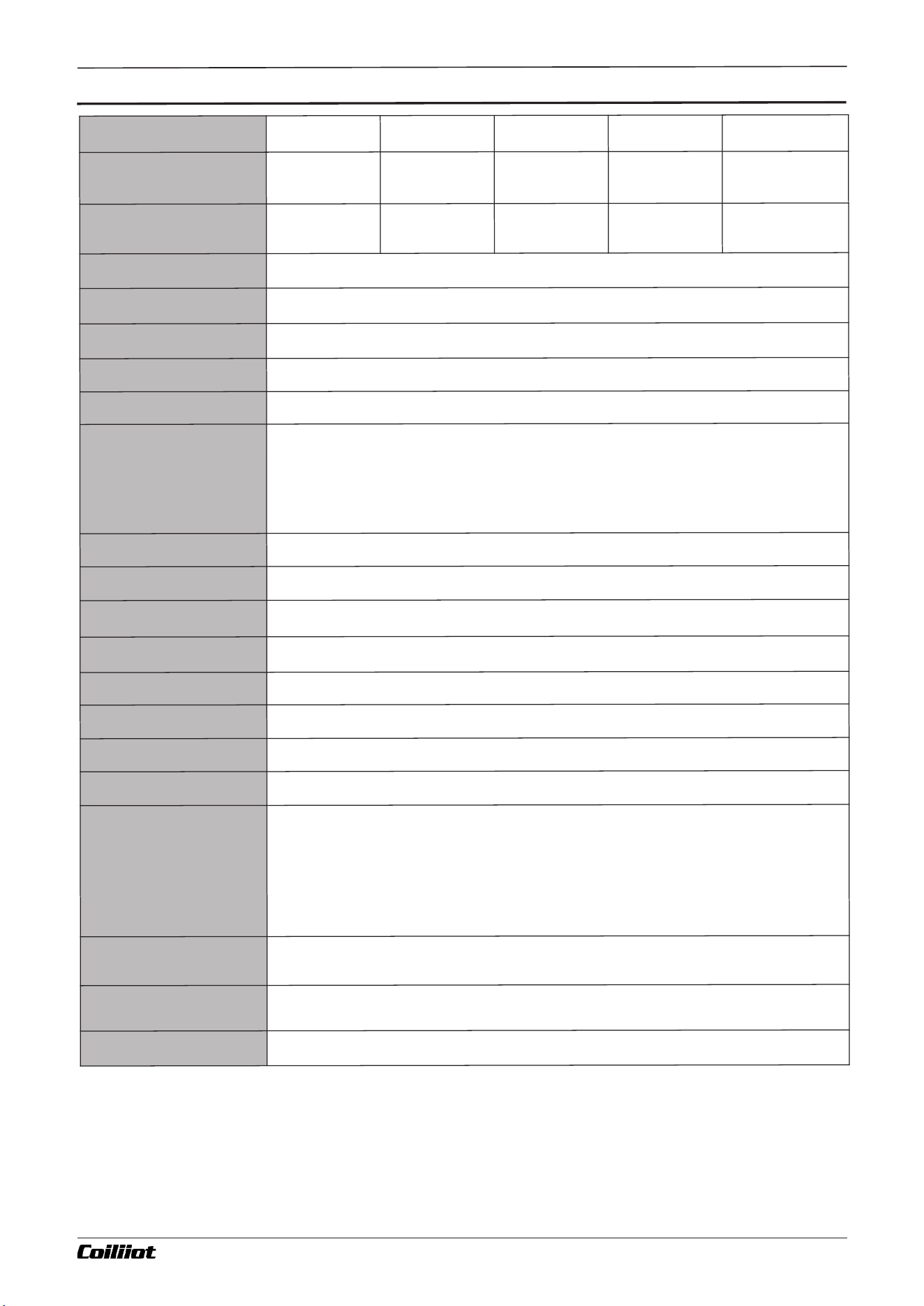
■ Technical Parameter2.
Page 3/19 pages in total
Ty
pe
G - type pa
n
el
D - typ
e pa
nel
A - t
y
p
e p
ane
l
E - ty
p
e pane
l
F - t
y
pe pa
n
el
P
a
nel S
i
z
e (
Wi
d
t
h * H
e
ig
h
t)
4
8
*4
8 m
m
1
.
89
*
1.8
9 i
n
72*
7
2 mm
2
.8
3*2.
83 i
n
96
*
96 mm
3.
7
8*
3
.
7
8 i
n
4
8*
9
6 m
m
1
.
8
9
*3.
78 in
96*
4
8 mm
3.6
2*
1
.
77 i
n
Dri
l
l G
a
p (Wi
dth * He
i
ght
)
4
5*
4
5 mm
1
.7
7*1
.
7
7 in
68
*
68 mm
2.
68
*
2
.
6
8 i
n
9
2*
9
2 m
m
3
.
6
2
*3.
62 in
4
5
*
9
2 m
m
1
.7
7*
3
.
62 i
n
9
2
*
45 m
m
3
.
62
*
1.7
7 in
M
ounti
ng Ty
pe
B
u
i
lt
-
in p
an
e
l moun
tin
g
Power s
u
pply
AC
10
0
~
24
0
V 50
/
60
H
z
;
o
r DC1
2
~24
V
V
ol
t
ag
e Ra
ng
e
8
5
%
~ 1
1
0%of th
e rat
e
d powe
r v
o
l
t
a
ge
P
o
w
e
r co
n
s
u
m
ption
A
C1
0
0~2
40V
: 5V
A O
R D
C
12
~2
4V
: 3
.
5VA
D
i
sp
l
a
y
L
CD dis
pl
a
y (wh
it
e f
o
r PV, g
r
e
e
n for SV
, li
ght o
r
a
n
ge f
or i
ndi
ca
t
or)
M
easu
rem
e
n
t Ra
n
ge
K
: (-5
0
~
1
3
00°
C / -5
8
~
2
3
7
2°F) S: (
-
50
~
170
0
°C / -
58~
3
09
2
°
F
) R: (
-
5
0
~
1
7
0
0°C / -
5
8
~
30
9
2
°
F)
T
: (
-2
00~3
50°C / -
3
2
8
~6
6
2
°F
) E: (
0~8
0
0°C / 3
2~1
4
72
°
F
) J
: (
0~1
000
°
C / 3
2
~
18
3
2°F)
B
: (
2
00~1
80
0
°
C / 3
9
2
~32
7
2°
F
) N: (
0
~1
3
0
0°C / 32~2
3
72
°
F)
C
u
5
0
: (
-5
0
~
15
0
°C / -
58
~3
0
2°
F
) P
t
1
00: (-2
0
0
~6
00
°
C / -3
28~
1
112
°
F)
Li
ne
ar S
ca
l
e
: -
9
999
~
320
0
0 (u
se
r de
fi
ned
)
De
cim
al P
oi
n
t P
osi
t
i
oni
ng
0
0
0
0
, 0
00.0
, 0
0.0
0
, 0.0
0
0 (a
dj
u
s
tabl
e ba
se
d on pa
ram
e
ter
s
)
Sam
p
l
i
ng Ac
cu
rac
y
±
0
.
2
5
%F
S
Sam
p
l
i
ng F
r
e
quenc
y
10 tim
es p
er s
ec
on
d
; w
h
e
n d
i
gi
t
a
l f
i
l
t
er
i
n
g i
s s
e
t t
o INF=
0, re
sp
o
ns
e tim
e is 0
.
5 se
co
nds
C
o
n
trol Met
h
od
O
N/O
F
F con
t
r
o
l, A
I F
UZ
Z
Y a
l
gori
thm
, PV t
ra
ck
i
ng a
n
d SV v
a
lu
e s
e
tt
in
g
C
o
nt
r
o
l R
a
n
g
e
0.
1~3
0
0
.0 s
ec
on
d
s
Re
lay O
u
t
p
u
t
5
A
/
250V
A
C OR 5A
/3
0VD
C
S
S
R D
ri
ve Vo
lt
a
ge Out
put
1
2
VD
C 50m
A max (u
se
d to dr
i
ve SSR re
la
y)
SC
R N
o
n
-
con
tac
t Outp
ut
0.
2A (co
n
tinuo
u
s
)
, 2
A (
2
0
m
s p
u
ls
e, 5
s p
eri
od
) 1
00
-
24
0
VAC
E
l
ect
romagn
e
t
i
c
C
om
pa
ti
b
il
it
y
E
l
ect
r
o
ma
gne
tic c
om
p
a
ti
b
il
i
ty com
pli
es w
it
h I
EC6
10
0
0
-4
-
4 (e
l
ec
trica
l f
a
s
t tr
a
n
s
ie
n
t b
u
r
s
t
) at
6
K
V
/
5K
Hz, IEC6
1
00
0
-4
-
5 (s
ur
g
e i
m
m
uni
t
y
) a
t 6K
V and 1
0
V/
m h
i
gh
-f
re
q
u
enc
y e
lec
tr
o
m
ag
n
e
t
i
c
f
i
e
ld i
nt
e
rf
er
en
ce
. Und
er t
hes
e c
ond
it
i
on
s, t
h
e i
n
s
trum
ent do
e
s no
t e
xp
e
rienc
e c
ras
hes o
r
i
n
correc
t I/O op
erat
i
on
s, a
nd t
h
e meas
u
r
em
ent v
alue fluct
u
at
i
on
s d
o not e
xce
ed ±
5
% of t
he
m
ea
s
ur
ed r
ang
e.
I
s
o
l
ation Vo
lt
a
g
e
I
np
u
t/o
u
tput
, p
ow
er o
ut
p
u
t
/
co
nt
rol mod
ul
e: ≥2
300
V
D
C; si
gna
l ter
m
i
na
l
s b
et
w
een pha
se
-to
-
p
has
e s
i
gn
als ≥6
0
0
V
DC
O
pera
t
in
g Temp
er
a
tur
e
-
10~5
5°C (
1
4~1
3
1°F) (
n
o c
o
nd
e
ns
at
i
on
, no ice f
o
r
m
a
t
i
o
n
), hu
mid
i
t
y
: 2
5
~
8
5
%R
H
S
t
o
r
ag
e
Tem
p
e
r
at
ur
e
25
~
65
°
C (-
1
3~1
4
9°F
) (
n
o c
ond
e
n
s
at
i
on
, no i
ce f
orm
at
i
o
n
), h
u
mi
d
i
t
y
: 2
5
~8
5
%
R
H
A FUZZY-903 : 9- i Technical Manual_Version number EN-V 01
Code
Description
N
None selected
R1
Single-circuit relay normally open contact switch output module.
Module capacity: 30VDC/3A, 250VAC/3A.
Q1
SSR Solid-state relay drive voltage output module, 12VDC/50mA
W1
Normally open isolated non-contact voltage output module, capacity: 100-240VAC/0.2A
W2
Normally closed isolated non-contact voltage output module, capacity: 100-240VAC/0.2A
Q7
Built-in SSR solid-state relay, interconnected with the meter’s power supply, directly outputs the power
supply voltage module (e.g., if the power supply is 220V, the output will be 220V; if the power supply is
110V, the output will be 110V). Suitable for small power loads of 1.5A/220V (customizable).
Code
Description
G
Panel size 48*48mm/1.89*1.89 in (width*height), drill gap 45*45mm/1.77*1.77 in
D
Panel size 72*72 mm/2.83*2.83 in (width*height), drill gap 68*68 mm/2.68*2.68 in
E
Panel size 48*48mm/1.89*1.89 in (width*height), drill gap 45*45mm/1.77*1.77 in
F
Panel size 48*48mm/1.89*1.89 in (width*height), drill gap 45*45mm/1.77*1.77 in
A
Panel size 48*48mm/1.89*1.89 in (width*height), drill gap 45*45mm/1.77*1.77 in
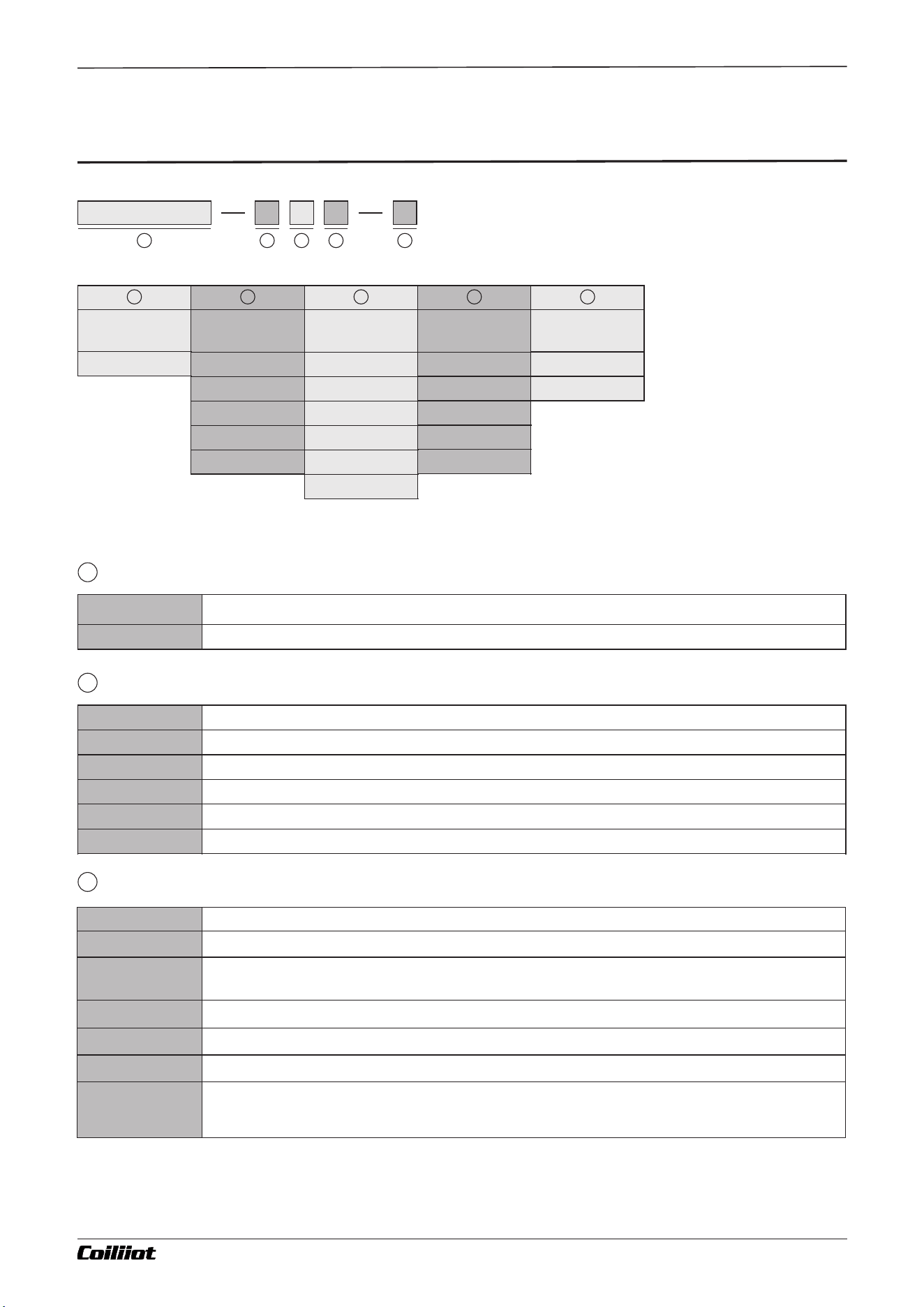
Chapter 3 Model definition
■3.Model definition
Page 4/19 pages in total
Panel size
G
D
E
F
A
Model
AiFUZZY903
ALM
Alarm output
N
R1
R2
R3
R4
OUTP Control
output
N
R1
Q1
W1
W2
Q7
Power supply
N
D
21
4
3 5
Indicates the installable module for OUTP control output
3
5
1
2
3
4
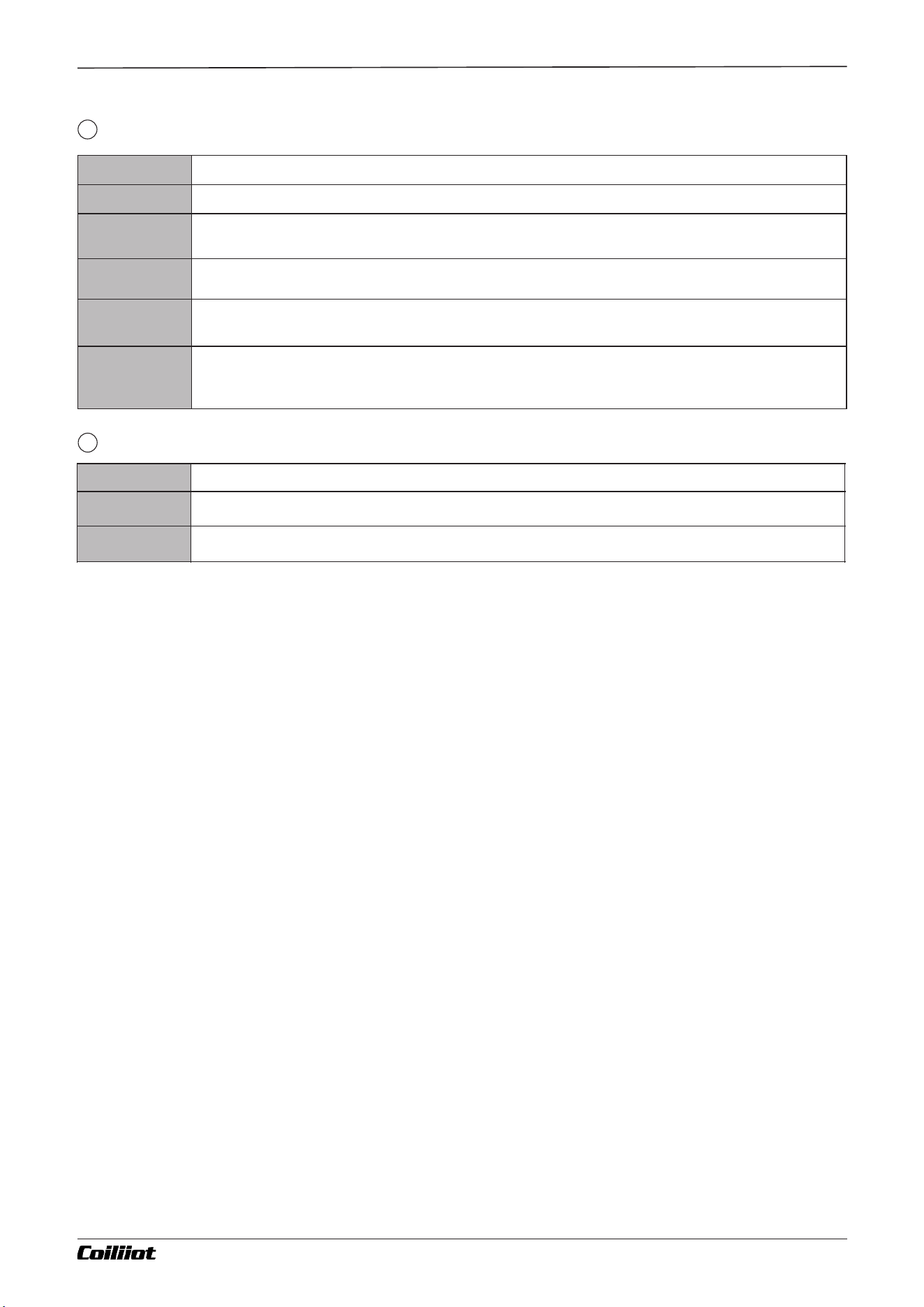
Code
Description
AiFUZZY903
Economical LCD Display PID Temperature Controller For General Use
Model
1
Size of the meter
2
A FUZZY-903 : 9- i Technical Manual_Version number EN-V 01
Page 5/19 pages in total
Chapter 3 Model definition
A FUZZY-903 : 9- i Technical Manual_Version number EN-V 01
ALM alarm output
4
Code
Description
N
100~240VAC power supply
D
12-24VDC power supply
Power supply
5
Code
Description
N
None selected
R1
Single output, AL1 alarm output (relay normally open contact output module),
contact capacity: 30VDC/3A, 250VAC/3A
R2
Dual output, AL1+AL2 alarm output (relay normally open contact output module),
contact capacity: 30VDC/3A, 250VAC/3A
R3
Single output, AL2 alarm output (relay normally open + normally closed contact output module),
contact capacity: 30VDC/3A, 250VAC/3A
R4
Dual output, AL1 (relay normally open contact output module)+AL2 (relay normally open + normally closed
contact output module)
contact capacity: 30VDC/3A, 250VAC/3A
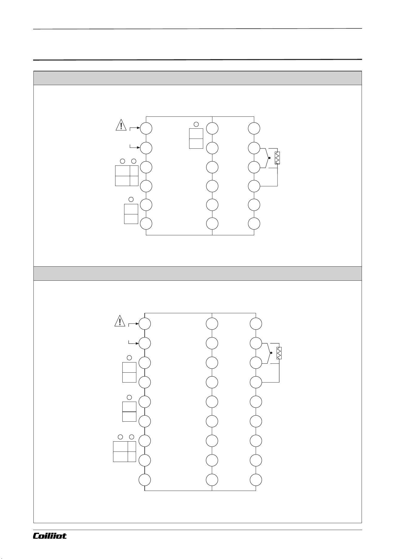
G Type panel (48×48mm)
D Type panel (72×72mm)
Chapter 4 Wiring diagram
■4.Wiring diagram
COM
COM
COM
NO
NO
NO
_
_
_
+
+
+
AL1
AL2
OP1
OP1
A
B
B
POWER
1
2
3
4
5
6
13
14
15
16
17
18
7
8
9
10
11
12
COM
NO
1
2
3
4
5
6
7
8
9
POWER
COM
NO
AL1
AL2
COM
NO
19
20
20
22
23
24
25
26
27
10
11
12
13
14
15
16
17
18
_
+
A
B
B
Page 6/19 pages in total A FUZZY-903 : 9- i Technical Manual_Version number EN-V 01
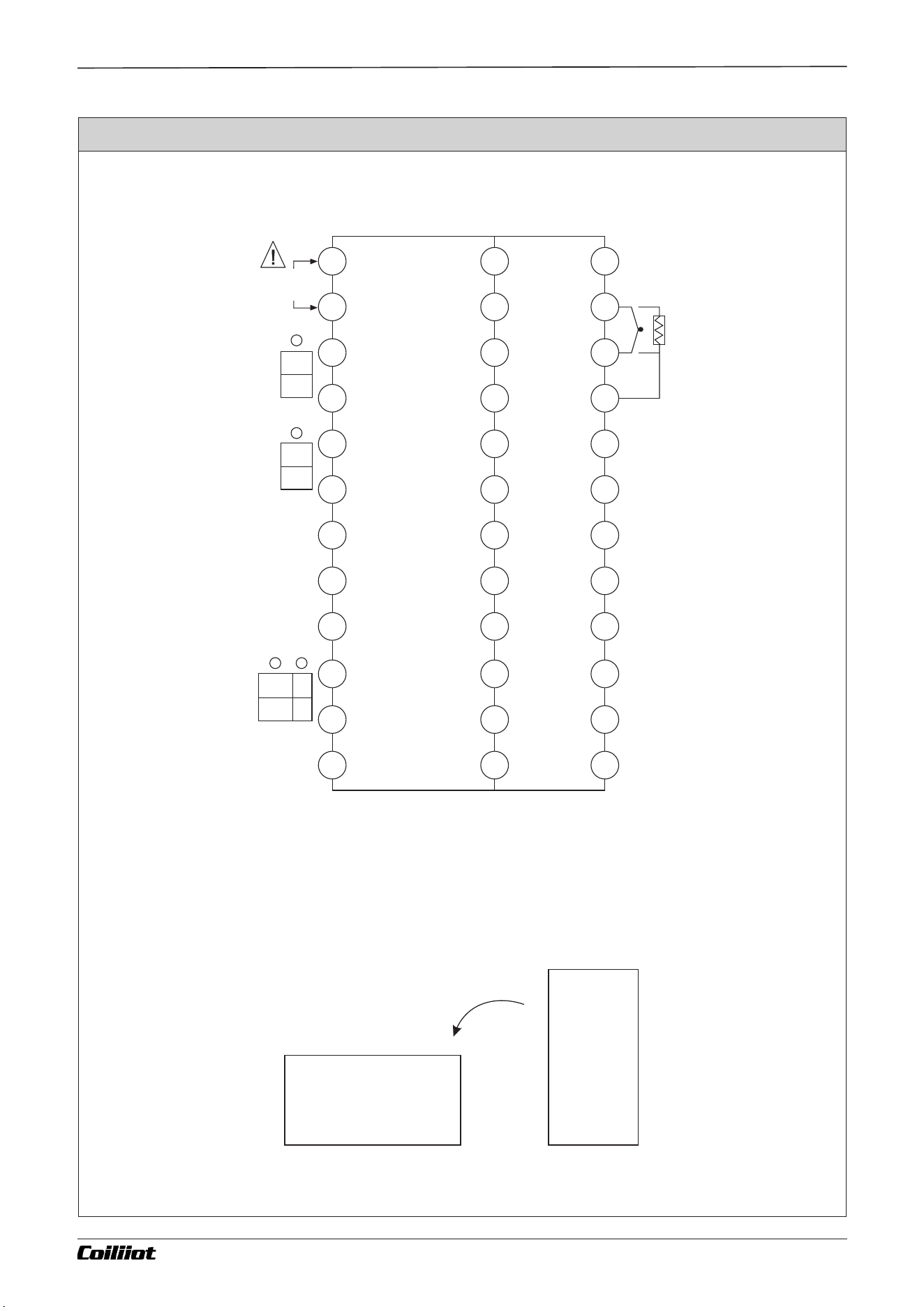
Chapter 4 Wiring diagram
25
26
27
28
29
30
31
32
33
34
35
36
13
14
15
16
17
18
19
20
21
22
23
24
1
2
3
4
5
6
7
8
9
10
11
12
COM
NO
AL1
AL2
COM
NO
POWER
_
+
A
B
B
COM
NO
_
+
OP1
E,F,A Type panel (48×96mm/96×48mm/96×96mm)
This wiring diagram is designed for viewing on A and E type panels. For the F type panel, which is horizontal,
the diagram should be rotated 90 degrees counterclockwise for proper viewing. The terminal numbers remain
unchanged.
Page 7/19 pages in total A FUZZY-903 : 9- i Technical Manual_Version number EN-V 01
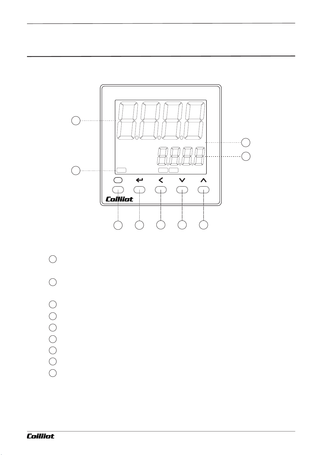
Chapter 5 Panel description
■5.Panel description
Page 8/19 pages in total
1
2
4
9
8
PV
SV
F
AiFUZZY-900
ºFºC
OP1
AL1 AL2
3
5
6
7
PV first display window (displays measured values, parameter names, etc.).
SV second display window (displays setpoint values, parameter values, etc.).
Temperature Unit .
Output indicators:OP1,AL1,AL2 indicators.
Parameter key: Enter/ exit parameter settings.
Return key: confirm and switch to the next parameter.
Data shift key.
Data decrease key.
Data increase key.
1
2
3
4
5
6
7
8
9
A FUZZY-903 : 9- i Technical Manual_Version number EN-V 01
.
.
.
.
.
.
.
.
.
.
.
.
2 Sec
2 Sec
2 Sec
2 Sec
2 Sec
The basic display
state
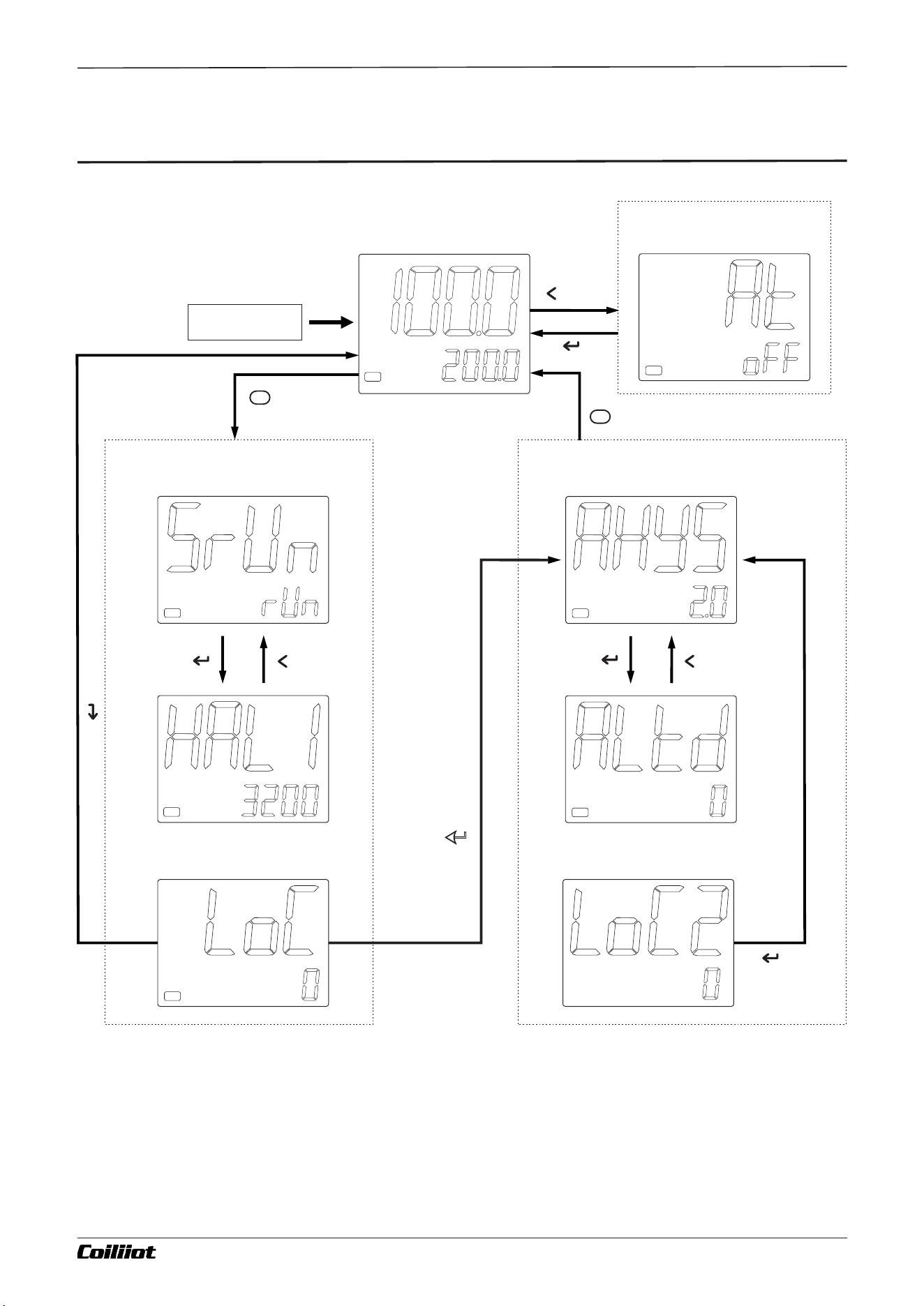
Set At=ON to start
Auto Tuning
POWER ON
Access to the system
parameter setting state
Omit
description
Access to the Field
parameter table
set Loc=800,Then press the key
to enter the system parameters
Page 9/19 pages in total
ºFºC
OP1
ºFºC
OP1
ºFºC
OP1
ºFºC
OP1
ºFºC
OP1
ºC
ºFºC
OP1
ºC
ºFºC
OP1
ºC
ºFºC
F
F
A FUZZY-903 : 9- i Technical Manual_Version number EN-V 01
Chapter 6 Display status and operation flowchart
■6.Display status and operation flowchart
If LOC ≠ 800, press the key
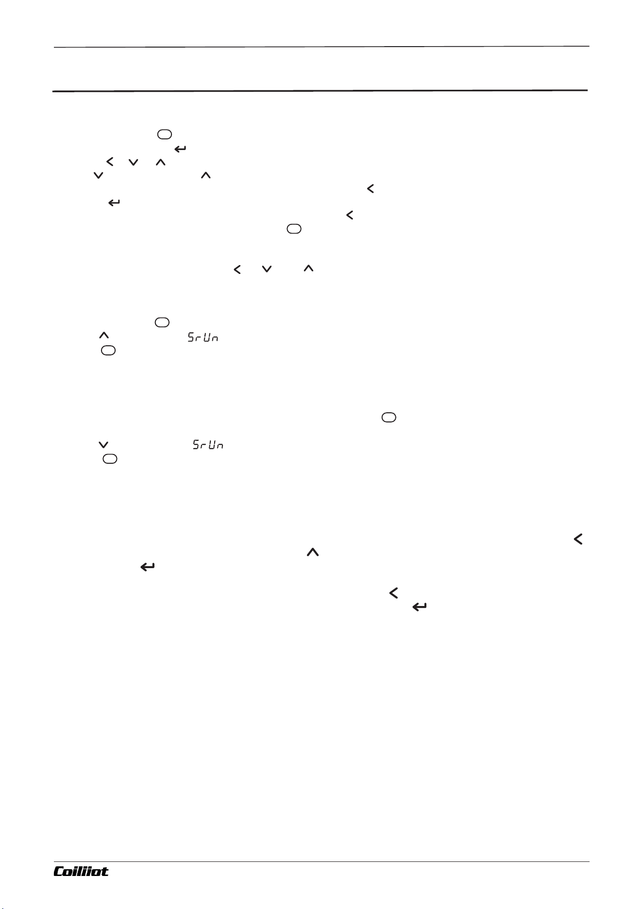
Page 10/19 pages in total
F
F
F
F
F
F
7.1 Parameter Setting
In the basic display state:
•Press and hold the key for about 2 seconds to enter the parameter setting mode.
•If LOC=800, press the key to access the function parameter settings.
•Use the , , , etc., keys to directly modify parameter values.
•Press to decrease and to increase values. Holding the keys enables faster adjustments.
•To navigate directly to a specific digit for editing, press the key, then adjust as needed.
•Press the key to save changes and move to the next parameter.
•To return to the previous parameter, press and hold the key for over 2 seconds.
•Exit to the basic display state by holding the key for 2 seconds.
7.2 Setting the given value
In the basic display state: Use the , , or keys to modify the given value directly.
7.3 Stop Control
In the basic display state:
Press and hold the key for about 2 seconds to enter the on-site parameter setting mode.
Use the key to set the (SrUn) parameter to Stop.
Hold the key for about 2 seconds to exit the parameter setting mode. At this point, the second
display window will show "Stop" and flash, indicating that the instrument has stopped output control.
7.4 Run control
If the instrument is in a stop control state:
The second display window will flash "Stop".Press and hold the key for about 2 seconds to enter the
on-site parameter setting mode.
Use the key to set the (SrUn) parameter to rUn.
Hold the key for about 2 seconds to exit the parameter setting mode.
At this point, the second display window will briefly display "rUn", and the instrument will resume normal
operation.
7.5 Auto Tuning
When the FUZZY+PID control method is selected (CntL=FPId), optimal PID parameters can be obtained
by running auto-tuning, achieving precise control without overshoot.Auto-tuning (AT):Press and hold
for 2 seconds to display the AT parameter. Press to change the "OFF" in the lower display window to
"ON," then press to confirm and start the self-tuning function. The lower display will flash and show
"AT," while the instrument automatically calculates the PID parameters after 2 oscillation cycles of
ON-OFF control. To cancel auto-tuning before completion, press again and hold it for about 2
seconds to call up the AT parameter, set "ON" to "OFF," and then press to confirm.
Notes:
The AiFUZZY algorithm combines fuzzy logic and proportional-integral-derivative (PID) control, offering
strong adaptability and robustness for stable performance in uncertain environments. When used for
the first time, the self-tuning function can assist in determining optimal PID parameters.
Results may vary based on system conditions. Before tuning, set the given value (SV) to a commonly
used or middle value. For systems like electric furnaces, use the maximum working value. Do not modify
the SV during the tuning process. The tuning duration may range from seconds to hours, depending on
the system.
The best results may not be immediate after tuning. Due to the self-learning feature, performance
improves over time.
A FUZZY-903 : 9- i Technical Manual_Version number EN-V 01
Chapter 7 Instrument operation method description
■7.Instrument operation method description
Chapter 8 Parameter list and function
■8.Parameter list and function
8.1 Field parameter
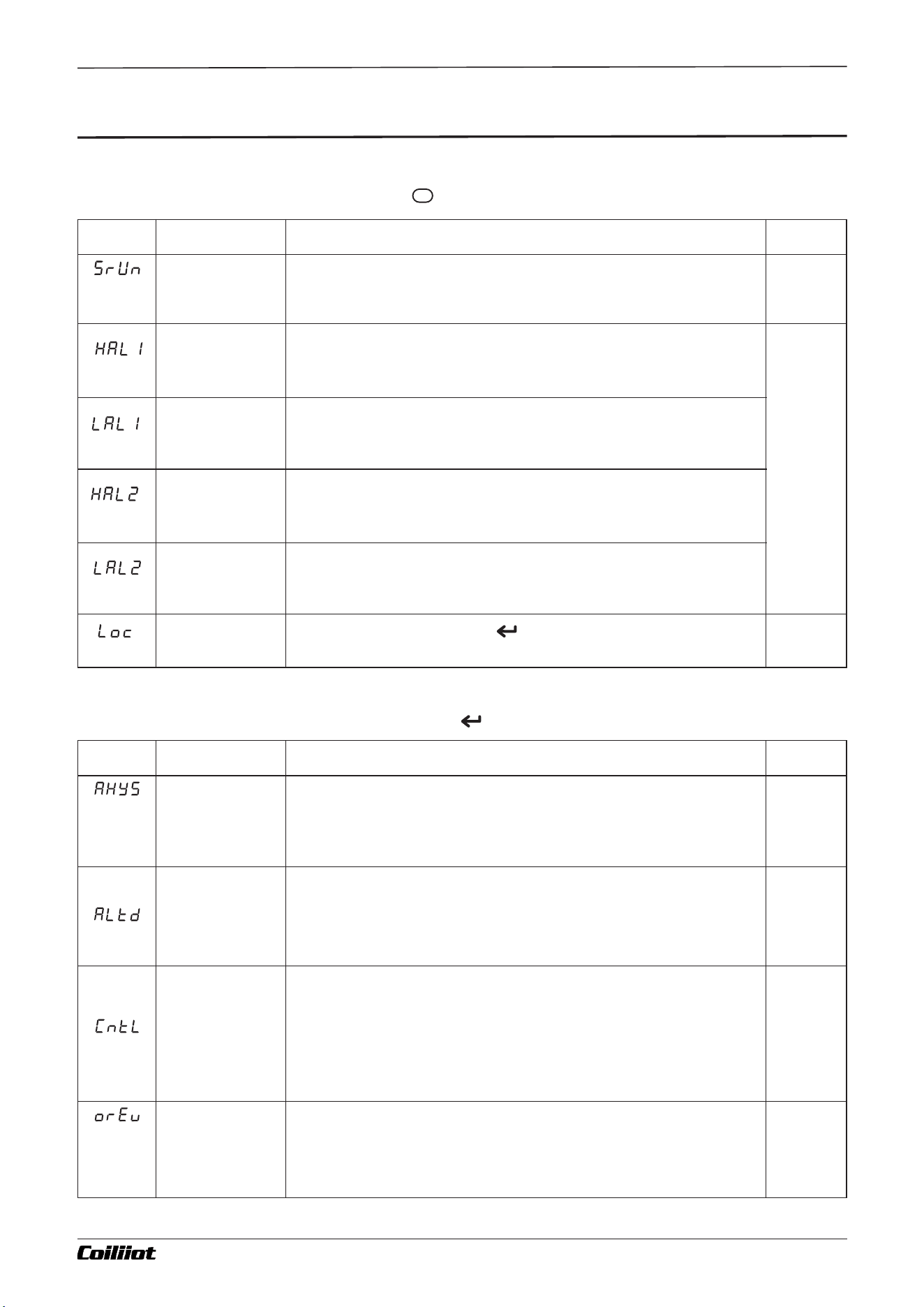
In the basic display state, press and hold key 2 seconds, enter the field parameters.
Code
Name
Description
Range
Operating
Status
Run: The instrument is in normal operating control status.
Stop: The instrument is in a stopped control output status, with
the SV window flashing.
Al1 max alarm
value
"HAL1" refers to the absolute value alarm or deviation value
alarm, defined by the "ALtd" parameter. When the value is set to
the maximum (3200), this function will be disabled.
-999 to
3200(Fact
ory default
values:
HAL1 and
HAL2 are
set to
3200, LAL1
and LAL2
are set to -
999)
Al1 min alarm
value
"LAL1" refers to the absolute value alarm or deviation value alarm,
defined by the "ALtd" parameter. When the value is set to the
minimum (-999), this function will be disabled.
Al2 max alarm
value
“HAL2" refers to the absolute value alarm or deviation value
alarm, defined by the "ALtd" parameter. When the value is set to
the maximum (3200), this function will be disabled.
Al2 min alarm
value
“LAL2" refers to the absolute value alarm or deviation value
alarm, defined by the "ALtd" parameter. When the value is set to
the minimum (-999), this function will be disabled.
System
Parameter Lock
Set LOC=800, then press the key to enter the system
parameters.
0~9999
Code
Name
Description
Range
Alarm
Hysteresis
Also known as alarm hysteresis or dead zone, this feature is used
to prevent the alarm relay from frequently activating at the alarm
threshold. It introduces a delay between the alarm output turning
ON and OFF to ensure stable operation.
0~200.0
(default
value: 2)
Alarm mode
ALtd=0: AL1 is the deviation value alarm, and AL2 is the absolute
value alarm.
ALtd=1: Both AL1 and AL2 are absolute value alarms.
ALtd=2: Both AL1 and AL2 are deviation value alarms.
0~9999
(default
value:0)
Control mode
onoF: On-off control, suitable for situations that do not require
high precision.
FPId: Advanced artificial intelligence AiFUZZY (FUZZY+PID)
control (Recommended for use).
default
value:
FPId
Direct/Reverse
Action
onr: Reverse acting. An increase in the measured variable causes
a decrease in the output, such as in heating control.
ond: Direct acting. An increase in the measured variable causes
an increase in the output, such as in cooling control.
default
value: onr
8.2 System parameter
In the field parameters, set Loc=800,then press key to enter the system parameters.
Page 11/19 pages in total
F
A FUZZY-903 : 9- i Technical Manual_Version number EN-V 01
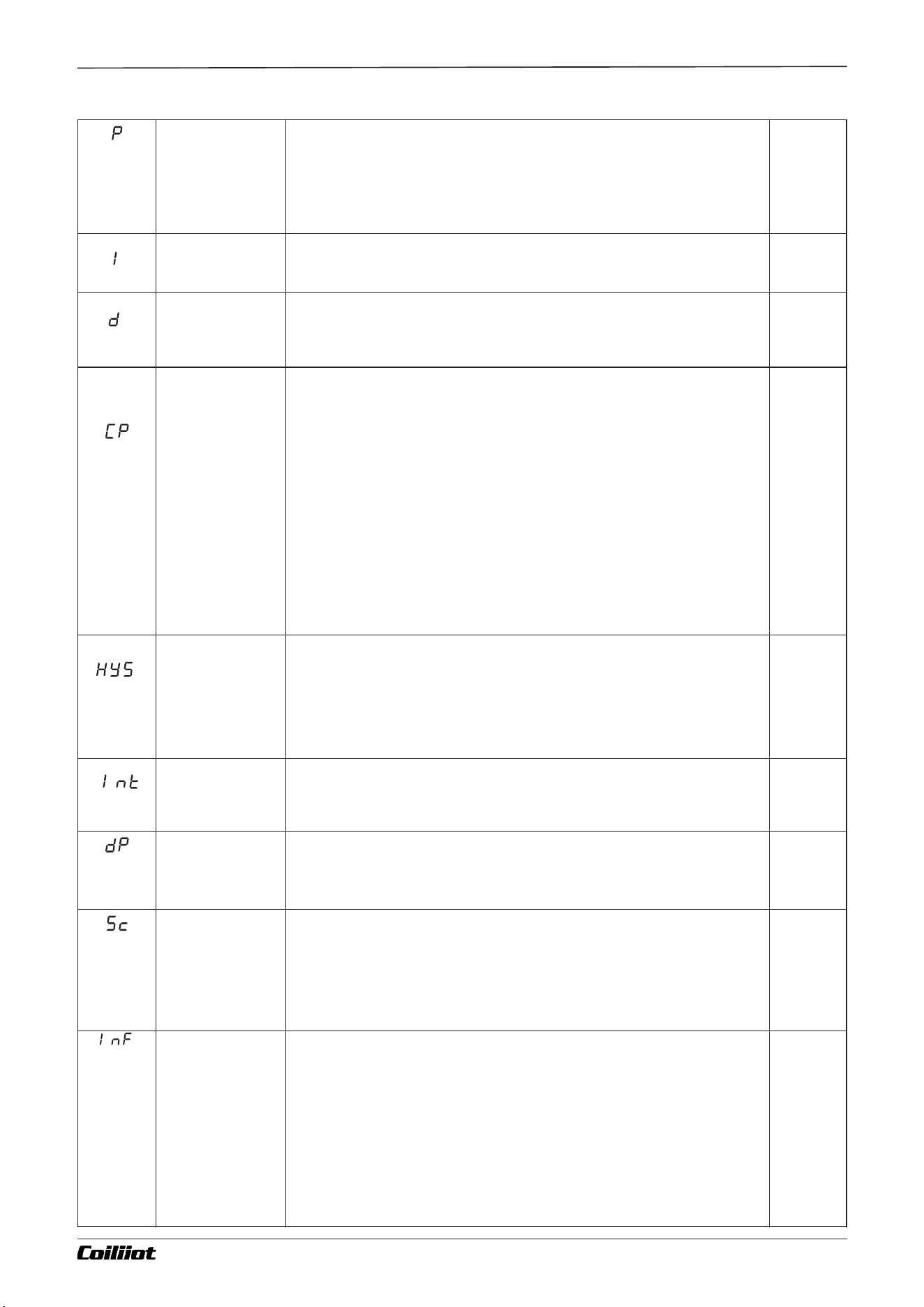
Proportional
band
The proportional band for FPID control is expressed in the same
units as the PV value, rather than as a percentage of the range.
Generally, optimal P, I, D, and CP values can be obtained through
auto-tuning. Alternatively, they can be manually entered if the
correct values are already known.
1~3200
default
value: 25
Integral Time
The integral time for FPID control is measured in seconds. When
I=0, the integral action is disabled.
1~9999
default
value:200
Derivative Time
The derivative time for FPID control is measured in 0.1-second
units. When d=0, the derivative action is disabled.
1~3200
(default
value:
50.0)
Control cycle
CP reflects the speed at which the instrument operator adjusts the
control. The size of the CP affects the control accuracy.
For SSR and SCR output control, a shorter control cycle is
preferred, typically between 0.5 to 3.0 seconds. For relay switch
outputs, a cycle time of 15 to 40 seconds is generally used.
When the output relay switches, the CP is limited to 3 seconds.
The self-tuning (AT) function will automatically adjust the CP to
the appropriate value, optimizing control accuracy and prolonging
the mechanical switch life.
When the control mode is set to CntL = onoF, the CP acts as the
output disconnect or power-on delay time.
0.2~
300.0
( default
value:
Relay
output
is 15.0,
SSR
output
is 2.0)
Control
hysteresis
HYS (Hysteresis) is used in ON-OFF control to prevent the relay
from frequently switching on and off. For a reverse acting
(heating) system: When PV > SV, the output turns off. When PV <
SV - HYS, the output turns on. For a direct acting (cooling)
system:When PV < SV, the output turns off. When PV > SV + HYS,
the output turns on.
0~
200.0
(default
value
2.0)
Input Signal
Selection of input Types for thermocouples or RTD:
K,E,J,N,Pt (Pt100)
default
value: K
Decimal point
0 :no decimal.
0.0:one decimal place.
default
value: 0.0
Input correction
SC is used to adjust the input signal to compensate for errors
caused by the transducer, input signal, or automatic cold junction
compensation of the thermocouple.
PV after compensation = PV before compensation + SC.
It is generally set to 0. An incorrect setting may result in
inaccurate measurements.
-199.9~
+400.0
(default
value:
0.0)
PV
input filter
The value of InF determines the ability to filter noise from the
input signal.
- When a large value is set, the measurement input stabilizes, but
the response speed slows down. Typically, it can be set between 1
and 3.
- If significant interference is present, gradually increasing the InF
value can help reduce momentary fluctuations in the measured
value, keeping them within 2 to 5 units.
- During metrological verification of the instrument, set InF to 0 or
1 to shorten the response time.
0~40
(default
value:
2)
Page 12/19 pages in total
Chapter 8 Parameter list and function
A FUZZY-903 : 9- i Technical Manual_Version number EN-V 01
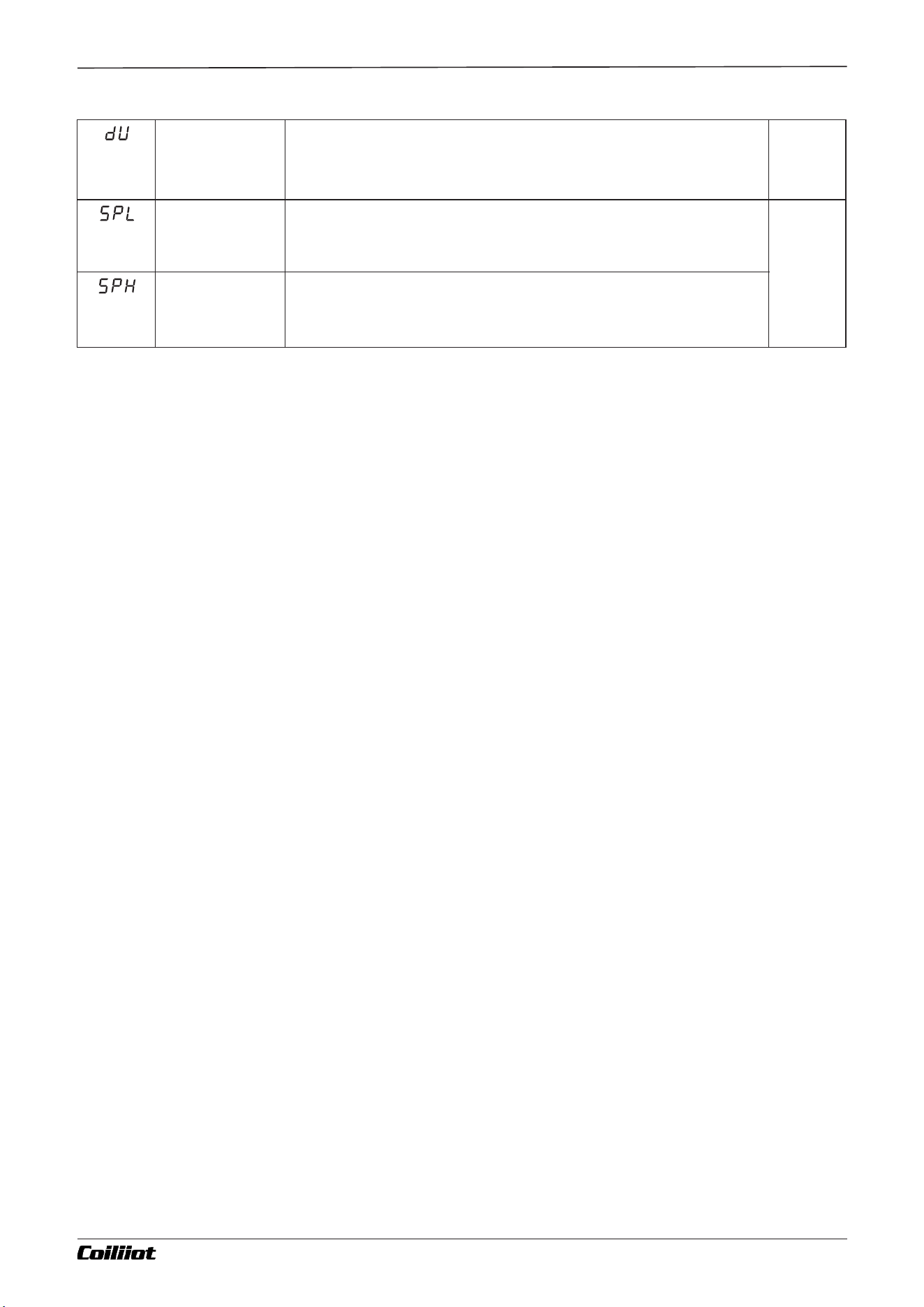
Temperature
unit
°C:celsius
°F:fahenheit
default
value: °C
Min of SV
Minimum value that SV is allowed to be.
-999~
3200
( default
value:
SPL is
-99,
SPH is
999)
Max of SV
Maximum value that SV is allowed to be.
Chapter 8 Parameter list and function
Page 13/19 pages in total A FUZZY-903 : 9- i Technical Manual_Version number EN-V 01
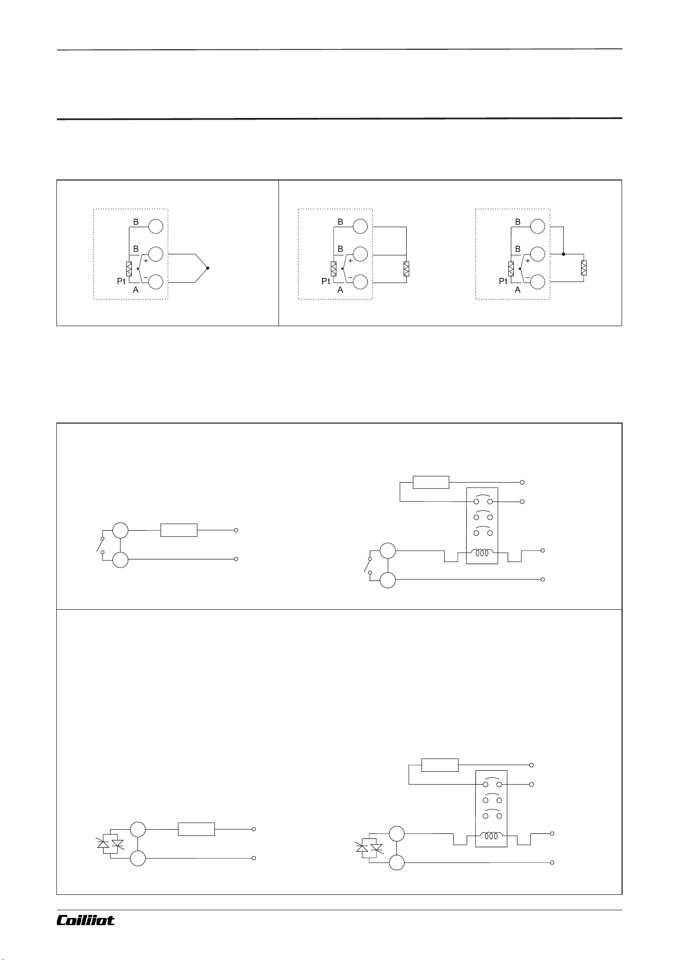
Chapter 9 Partial application wiring methods
■ .9 Partial application wiring methods
9.1 The wiring method of the input signal
Thermocouple Input
RTDs Input
TC
Input
RTC
Input
Three-wire
RTD
RTC
Input
Two-wire
RTD
If the input wiring is incorrect, the sensor is damaged or out of range, or the Int setting does not match the input
sensor type, the second display window will show a flashing "orAL" warning. Once these issues are resolved, the
instrument will return to displaying the measured values normally.
9.2 Main control output wiring method
● Solid-State SCR Switch Output (W Module for OUT port)
The new SCR solid-state switch module can replace the relay contact switch. Compared to the relay contact
output module, the W module offers a longer life-span and lower interference. It significantly reduces
equipment interference and sparking, improving the stability and reliability of the system. It can directly
control resistive loads up to 1A/240V (e.g., controlling a 250W heating element). For loads greater than 1A,
an AC contactor can be used to control larger currents. Since the driving element is an SCR, this module is
suitable only for controlling 100~240VAC power supplies and cannot be used for controlling DC power supplies.
Relay output ( R Module for OUT port)
100~240V
Main power
Drive contactor control load
Max. 1A
Resistive load
Load
100~240V
Main power
Direct control load
Contactor
100~240V
Main power
Load
OP1
OP1
100~240V
Main power
Contactor
100~240V
Main power
Drive contactor control load
Load
Max. 3A
Resistive load
Load
100~240V
Main power
Direct control load
OP1
OP1
Page 14/19 pages in total A FUZZY-903 : 9- i Technical Manual_Version number EN-V 01
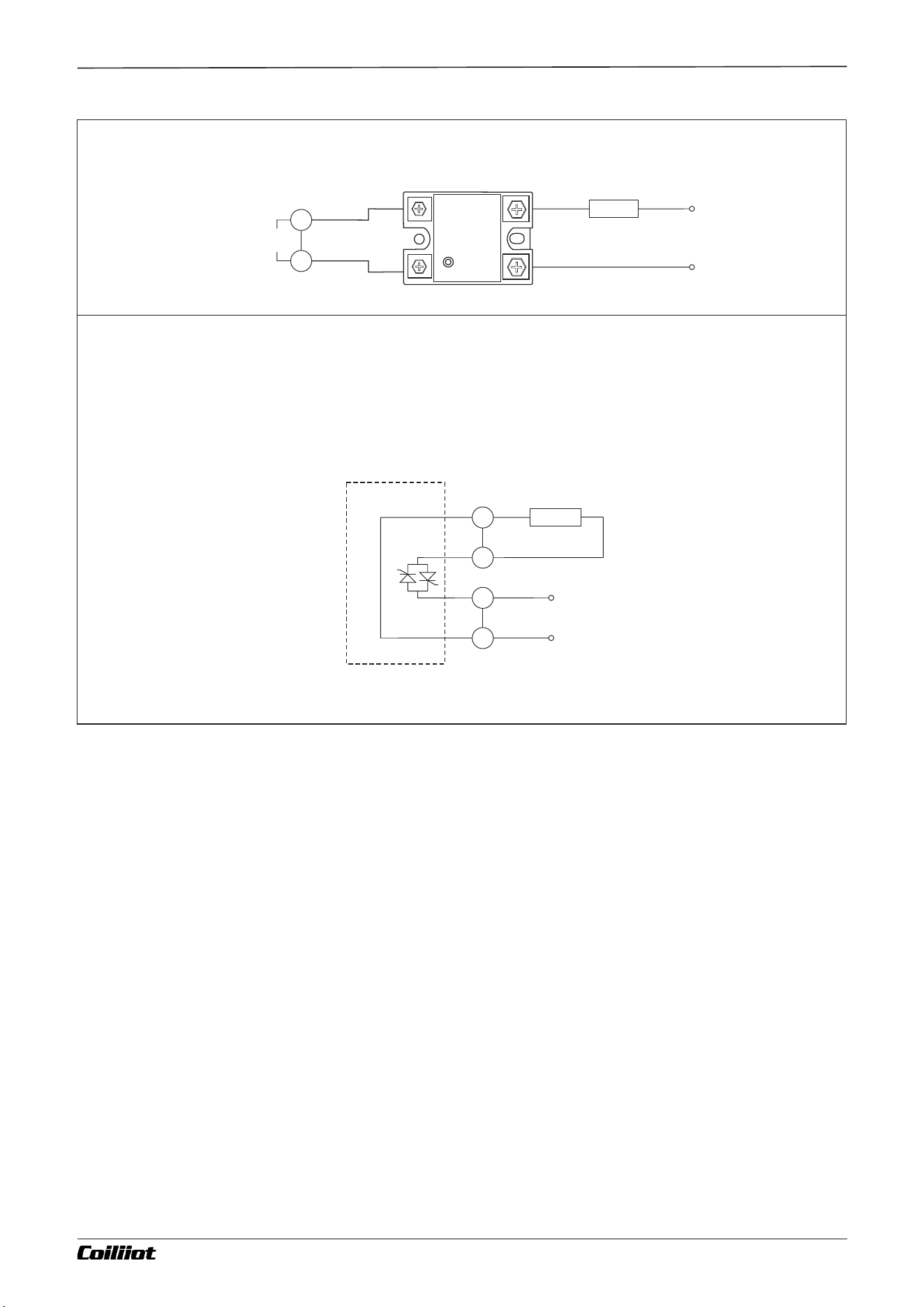
12V SSR drive voltage output(Q module for OUT port)
Load
Max. 1.5A
Resistive load
● Built-in SSR for Direct Load Power Output (Q7 Module for OUT port)
The built-in SSR (Solid-State Relay) is internally connected to the instrument's power supply, allowing for direct
load power output. For example, if the instrument is powered by 220V, the output will be 220V; if the instrument is
powered by 110V, the output will be 110V. This is suitable for small power loads up to 1.5A/220V (needs
customization)
OP1
Internal circuit
diagram
instrument
power supply
100~240V
Main power
Load
1- OUTPUT- 2
SSR
INPUT
4-3-2VDC+3
+
-
OP1(SSR drive
voltage output)
Chapter 9 Partial application wiring methods
Page 15/19 pages in total A FUZZY-903 : 9- i Technical Manual_Version number EN-V 01
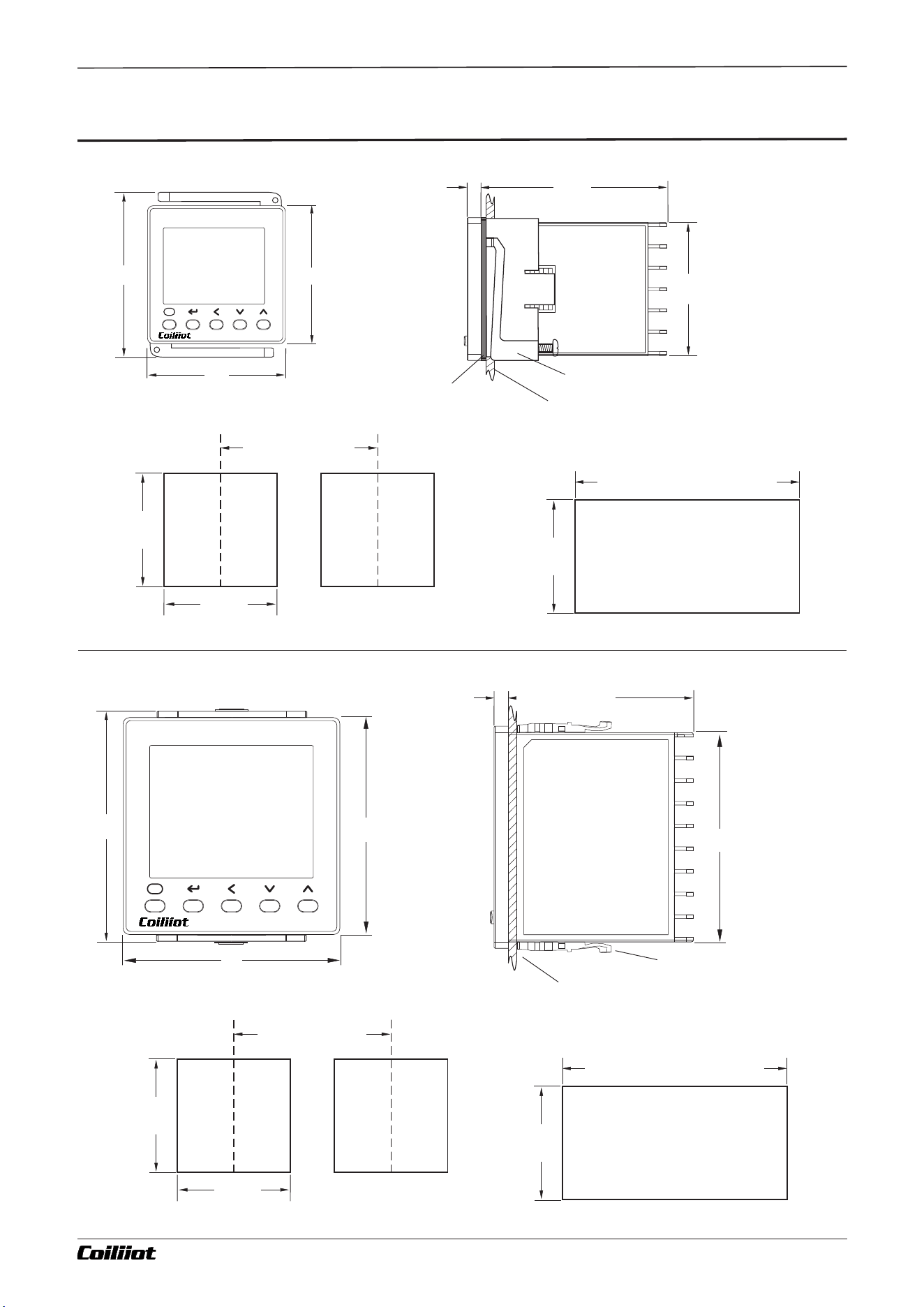
Chapter 10 Dimensions and installation instructions
Waterproof sealing ring
(Accessory, purchased
separately)
Mounting Adapter(Accessory)
Mounting Adapter(Accessory)
45
45
68
68
+0.6
+0.6
+0.6
+1.0
+1.0
+0.6
-0
-0
-0
-0
-0
-0
45
68
+0.6
+0.6
-0
-0
68
60
4.7
65
4.7
45
G-types panel
D-types panel
Indicates the cross-section of the cabinet panel.
The thickness of the panel must be 1 to 5mm
Indicates the cross-section of the cabinet panel.
The thickness of the panel must be 1 to 5mm
78
72
72
48
58
48
■10.Dimensions and installation instructions(mm)
Single Mounting Hole Dimensions
Single Mounting Hole Dimensions
SV
PV
F
AiFUZZY-900
PV
SV
F
AiFUZZY-900
(48XNumber of units - 2. 5)
(48XNumber of units - 2. 5)
When tightly installed
When tightly installed
Minimum 60 for
multiple installations
Minimum 100 for
multiple installations
Page 16/19 pages in total A FUZZY-903 : 9- i Technical Manual_Version number EN-V 01
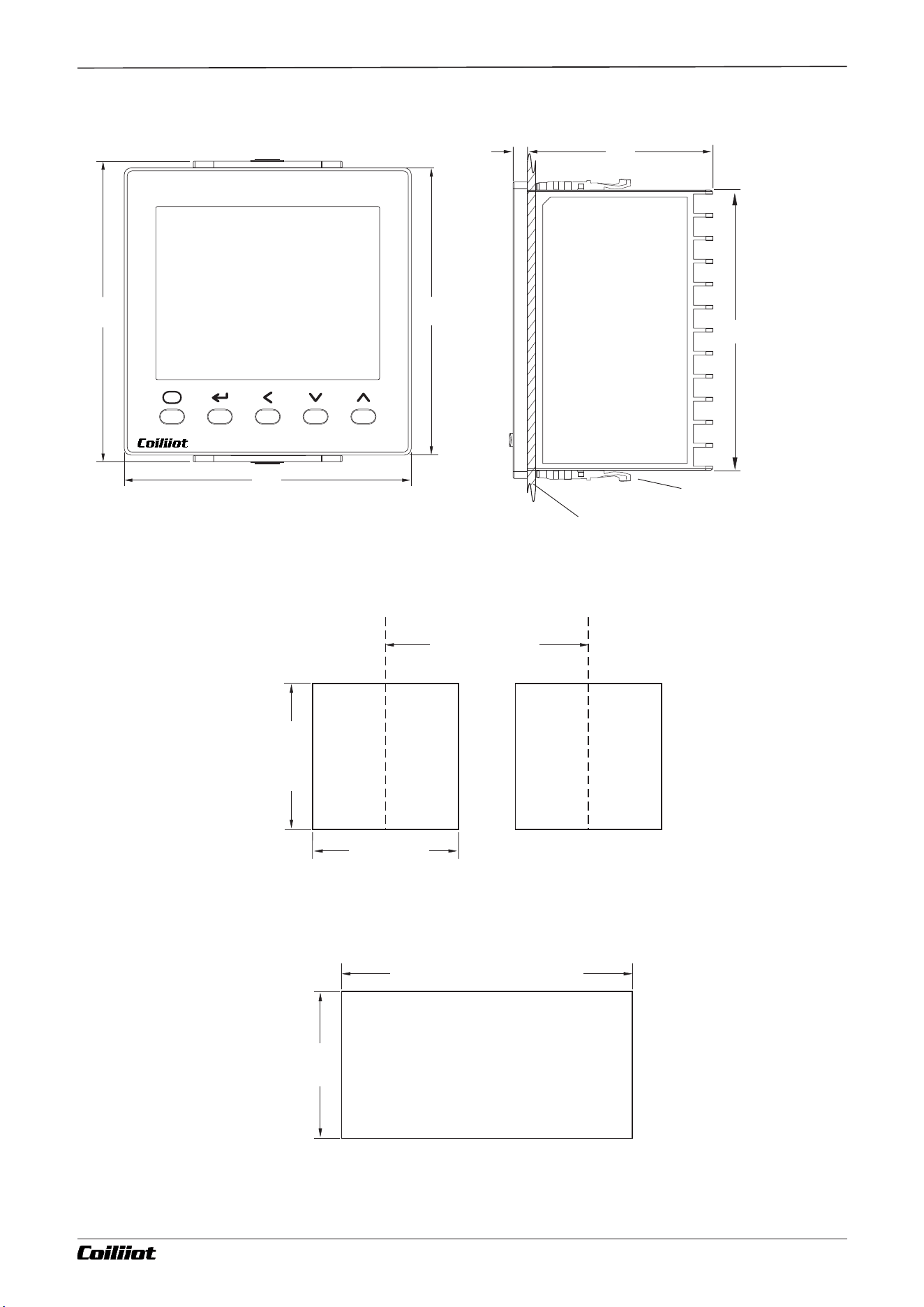
Mounting Adapter(Accessory)
+1.0
-0
Indicates the cross-section of the cabinet panel.
The thickness of the panel must be 1 to 5mm
Single Mounting Hole Dimensions
(48XNumber of units - 2. 5)
When tightly installed
Minimum 120 for
multiple installations
A-types panel
92
60
4.7
100
96
96
PV
SV
F
AiFUZZY-900
92
92
+0.6
+0.6
-0
-0
92
+0.6
-0
Chapter 10 Dimensions and installation instructions
Page 17/19 pages in total A FUZZY-903 : 9- i Technical Manual_Version number EN-V 01
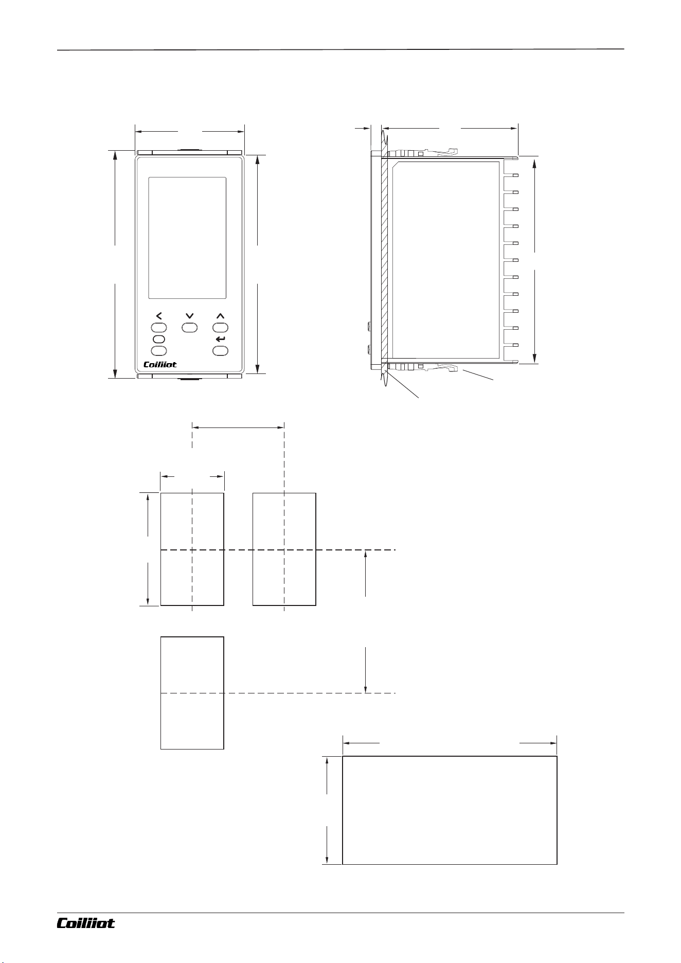
E-types panel
PV
SV
MV
F
Ai FUZZY-900
48
100
96
92
60
4.7
45
+0.6
-0
92
+0.6
-0
92
+0.6
-0
Mounting Adapter(Accessory)
+1.0
-0
Indicates the cross-section of the cabinet panel.
The thickness of the panel must be 1 to 5mm
Single Mounting Hole Dimensions
(48XNumber of units - 2. 5)
When tightly installed
Minimum 60 for
multiple installations
Minimum 120 for
multiple installations
Chapter 10 Dimensions and installation instructions
Page 18/19 pages in total A FUZZY-903 : 9- i Technical Manual_Version number EN-V 01
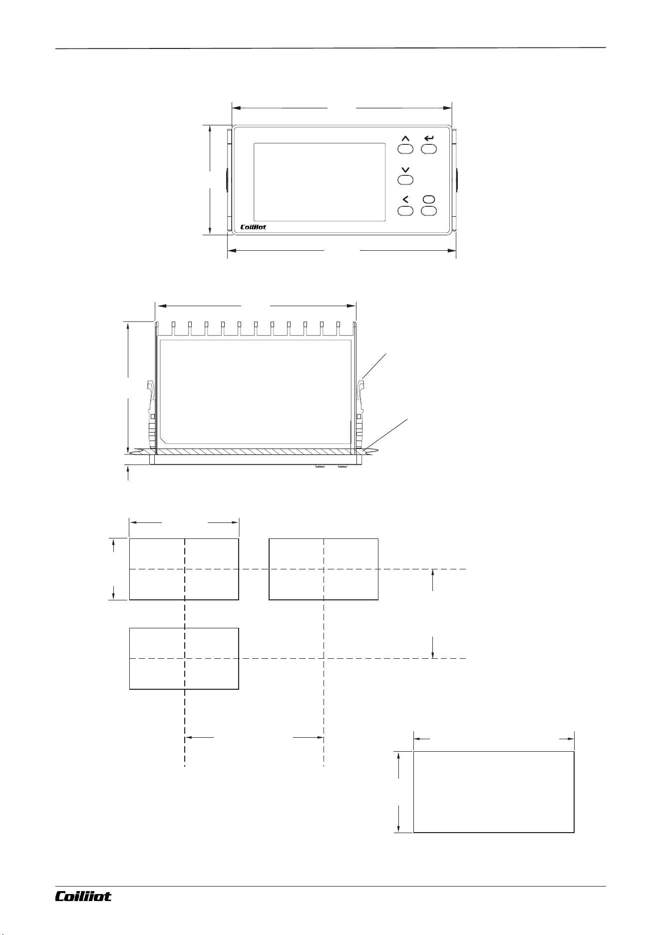
F-types panel
96
100
48
92
60
4.7
PV
SV
F
Ai FUZZY-900
45
+0.6
-0
92
+0.6
-0
45
+0.6
-0
Mounting Adapter(Accessory)
+1.0
-0
Indicates the cross-section of the cabinet panel.
The thickness of the panel must be 1 to 5mm
Single Mounting Hole Dimensions
(48XNumber of units - 2. 5)
When tightly installed
Minimum 60 for
multiple installations
Minimum 120 for
multiple installations
Chapter 10 Dimensions and installation instructions
Page 19/19 pages in total A FUZZY-903 : 9- i Technical Manual_Version number EN-V 01