Operating instruction
JEABONG Diesel Air Heater
Installation instructions
Operation instructions
Maintenance instructions

Summary
The diesel air heater produced by our company is a kind of volatile atomization air heater, which is driven
by 12V DC power supply, which is fully automatic program control. The product uses diesel fuel as fuel,
blowing out hot gas, and the temperature is adjustable.
Main technical parameters and shapes
Fuel
Model number
Voltage
Size
Fuel consumption
Weight
diesel oil
1KW/8KW
12V
38*25*29
0.16-0.52
7.5KG
When using 12V DC power supply, a separate wire is provided. When using indoor 110V power
supply, please use the matching power supply.
Precautions
Please read the instruction manual before installation and use.
This heater has the following features:
1. Equipped with a 110V power supply, it can use either 110V AC power or a 12V battery (battery output
current ≥16A).
2. Features voice broadcast function.
3. Automatically starts and stops according to the set temperature.
4. Equipped with Bluetooth functionality, making operation via mobile phone more convenient; various
heater parameters can be viewed on the phone.
5. The heater is equipped with a side exhaust pipe and an air intake filter, so it can be placed directly
outside the tent and connected to the inside of the tent via a corrugated pipe, making it very convenient to
use.
6. The built-in altitude chip can measure the approximate altitude (high precision is not required, and an
error is acceptable). Based on the altitude, it automatically adjusts the heater fuel frequency and fan speed.
This makes it easier for the heater to ignite successfully and for combustion to be complete, reducing black
smoke and carbon buildup.
After reading and understanding it, it is best to connect a power source in an open area, check the
switch instructions, download the mobile app on your phone, and familiarize yourself with the app's
functions. Add diesel fuel, turn on the machine, and observe that the heater is working normally before
actually installing it in the desired location.
Installation process:
1.The suitable position should be selected when the heater is installed so as to facilitate the
maintenance in the future.
warning:The temperature of the exhaust pipe is very high, away from the oil and inflammable
materials.
2.The heater is installed horizontally. After the position is selected, two holes shall be opened according
to the position of the air intake and Exhaust gas exit for passing through the air intake pipe and stainless
steel exhaust pipe.Aluminum-plastic tube is installed on intake port, fix with clamps. The other side plus air
filter is fixed with Clamp. This heater is equipped with a stainless steel pipe for side exhaust gas discharge,
which can be used or removed according to one's own usage situation. This device is convenient for mobile
use, and another stainless steel pipe is inserted into the side exhaust stainless steel pipe and fixed with a
clamp.If the exhaust pipe needs to extend downwards outside the car or outdoors, you can remove the
stainless steel pipe on the side discharge and install another stainless steel pipe.The exhaust pipe must be

led out of the car, and it is tilted and fixed so that the condensate is discharged.Then install the muffler and
secure it with clamps.
3.The temperature of the exhaust pipe is very high, away from the oil and inflammable materials.
Combustion air intake and Stainless steel exhaust pipe of the exhaust port ban installing upwind. Do not use
the intake pipe and stainless steel exhaust pipe incorrectly.The hot air outlet of the diesel heater is
connected and fixed with a special corrugated pipe, and the outlet of the corrugated pipe is connected to
the air vent and fixed with a clamp.
4.The circuit layout should be kept away from high temperatures, compression is prohibited, the plug
connection should be firm, the power supply voltage should be kept normal, and it should be connected to
the heater.Choose either 110V AC power or 12V DC power according to your needs.
5.Press the On/off switch, the LCD screen displays ON, and the machine starts to work. First, the air fan
rotates, the Glow plug starts to warm up, and then the oil pump starts to make a clattering sound. This is
when the oil pump starts to pump oil. After a while, diesel enters the machine, and after atomization
ignition, the machine starts to ignite. Since there is air in the oil pipe at the beginning, the internal
combustion may be abnormal, or E-10 failure may occur, restart the machine, Due to the diesel just
entering the heater, there may be some air or too much diesel entering the heater, which may cause noise
in the machine. After running for a period of time, it will return to normal. After the machine self checks
and determines that it is working properly, it will operate in the mode displayed on the LCD switch. This is
the start-up process of the heater, which is a fixed mode. After the machine runs normally, adjust the
required mode. Please refer to the instructions for the LCD switch.
6.Shut down press On/off switch. (LCD flash “OFF”). the Air fan continue to roll at this moment, After
the heat dissipation of the heater is completed,stop running, it will take some time to finish, this process
cannot be forced to stop the power supply, causing damage to the machine.
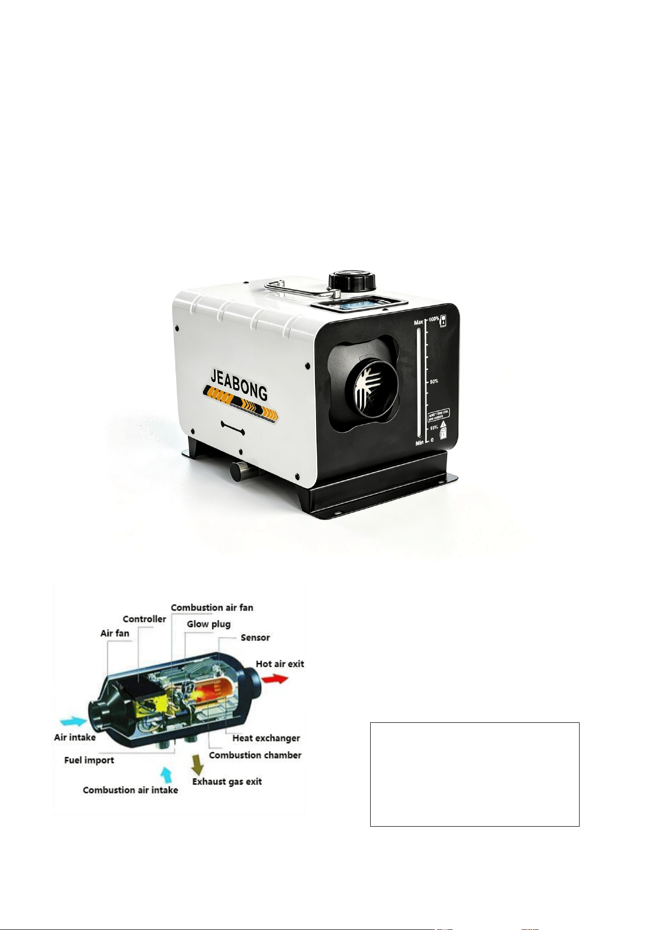
7.The Air intake 、Hot air exit 、Exhaust gas exit、Combustion air intake are forbidden to clog.
8.Please note to add diesel before it drops below 10%.
Maintenance Instructions
1.In the unused season, if the conditions permit, it is recommended that the whole system should be
removed and properly stored after cleaning, or the various tuyere should be packed with plastic to prevent
debris from entering and causing blockage;
2.After a long period of idleness, before use, a thorough examination shall be conducted to check
whether the ventilation ducts, combustion air lines and exhaust pipes are blocked, broken and loosened;
3.Check whether the oil pipe is old and loose, whether the filter is blocked and whether the fuel tank is
aging;
4.Check whether the line is loose, corrosive or fractured;
5.Run for 10-20 minutes. If abnormal burning sounds or obvious smell of fuel can be detected for a
long time, the heater must be turned off and the professional personnel should be treated.

Panel fault code description:
Fault code
Machine failure
Treatment method
E-01
Power supply undervoltage
Insufficient supply voltage
Power supply voltage needs to be
increased
E-02
Power supply overvoltage
Supply voltage too high
The supply voltage needs to be
reduced
E-03
glow plug
Check whether the piston is open
circuit
Or short circuit
E-04
Oil pump failure
Check the oil pump and harness
Check for wire breakage and short
circuit
E-05
The machine is overheating
Check the temperature sensor on the
housing.
Or if the fan speed is abnormal
E-06
Motor failure
Check magnet polarity, hall sensor
position, or loose motor terminal
Move
E-07
Disconnection fault
Check panel connection plug, blue
Loose or broken harness
connection
E-08
The flame went out
Check for air or oil in the oil circuit
Blockage due to wax deposition,
resulting in poor oil supply
E-09
Faulty sensor
Check if the sensor plug is loose
Moved, or broken wire, short
circuit
E-10
Ignition failed
Check whether the oil circuit is
blocked, or the oil inlet is not
smooth, the oil pump is stuck, and the
secondary ignition fails due to the
blockage of the volatile screen caused
by the oil problem.
It often burns
Note: if the above operation does not solve the problem, the controller needs to be replaced.
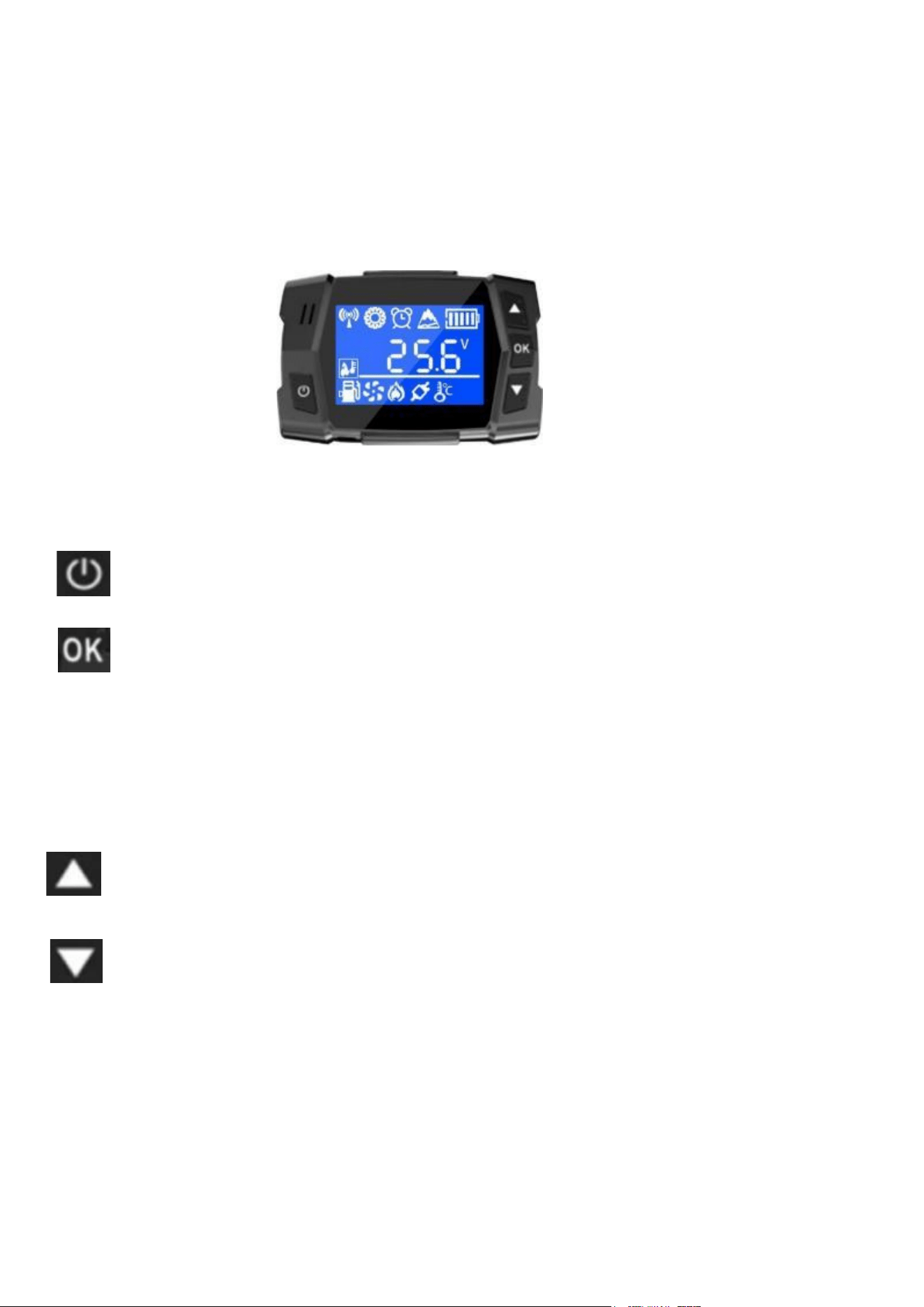
Blue LCD Bluetooth witch Instructions
1. Key Function
=> Press and hold to turn on/off the heater
=> Short press to query the working status of the machine; Press
continuously for a short time to open the corresponding function
and press for a long time to enter the timing setting and parameter
setting;
After entering the timing setting and parameter setting, short press to confirm and
Long press to return to the main interface.
=> Short press to increase the working temperature or oil quantity; press and hold to
open the remote control pairing function
=> Short press to lower the operating temperature or oil quantity; press and hold
to open the manual oil pumping function
2. Function Introduction
2.1 Mahine Working Status Query Function
2.1.1 Briefly press the OK key once
2.1.2 Ambient temperature display > Shell temperature display > Set temperature or gear display >
Power supply voltage display > Altitude display > Timed startup time or shutdown time
display (Timed startup or shutdown time is not set and is not displayed)

2.2 Temperature Control Mode Switching Function
2.2.1 Press the OK key twice in a row.
2.2.2 In automatic temperature control mode, the switch displays AT, and the temperature is
represented by digital ℃; In manual temperature control mode, the switch displays MT, and
the L-digit represents the gear.
2.3 Voice Type Switching Function
2.3.1 Press the OK key three times in a row.
2.3.2 Switch the type of voice broadcast: a total of four countries of voice, cycle switch in
2.4 Temperature Unit Switching Function
2.4.1 Press the OK key four short times in a row
2.4.2 Degrees Celsius shows℃,Degrees Fahrenheit shows
2.5 Automatic Start-Stop Function
2.5.1 Press the OK key five short times in a row
2.5.2 Enable the automatic start-stop function to display AC-1; Turn off the automatic start-
stop function to display AC-0.
2.5.3 The automatic start-stop function is that when the ambient temperature is 2 ℃ or
more lower than the set temperature, the machine will start automatically; When the
ambient temperature is 1 ℃ or more than 1 ℃ higher than the set temperature, the
machine will automatically shut down.
2.6 Extreme Thermal Mode Function
2.6.1 Press OK six short times in a row
2.6.2 Turn on the extreme hot mode function to display HO-1; HO-0 is displayed when
the extreme hot mode function is turned off
2.6.3 The function of the extreme heat mode is: after it is turned on, the machine will
automatically increase the pump oil quantity and adjust the air-oil ratio, so that the
machine can heat quickly in a short time.
2.7.1 Press the OK key seven times in a row
2.7.2 After opening, the operation switch has voice, and after closing, there is no voice prompt.
2.8 Remote Pairing Function
2.8.1 Remote control pairing method: long press the "up key" to open the remote control pairing
function, the switch displays HF-1 or HF-2, the remote control signal can be selected through
the up and down key, select the HF-2 signal, short press the"remote control power key" to
start the machine, after the switch is successfully paired with the remote control, the switch
automatically returns to the main interface.
2.9 Manual Oil Pumping Function
2.9.1 Long press the "Down" key to open the manual oil pumping function interface, and the
switch will display "H oF "; short press the" Up "key to start the manual oil pumping,
and the switch will display" H on ""; when the fuel reaches the oil inlet of the
machine, short press the "Down" key to stop the manual oil pumping, and the switch will
display "H OF ", short press" OK "to return to the main interface.
Note: When the fuel reaches the oil inlet of the machine, it will stop. If too much fuel enters
the machine, there will be black smoke when the machine is started.
2.10 Timing Settings
2.10.1 Press the "OK" key for a long time to enter the timing setting, the status bar on the switch
displays the alarm clock icon, the interface displays "1 oF", "1" indicates that the timing
startup time is set, "oF" indicates that the state is off, press the "Up" key for a short time to
start the timing startup time setting, "1 on" is displayed, "on" indicates that the state is on.
Short press the "OK" key to enter the setting
2.10.2 Timing is a countdown mode, the maximum time is set to 99 hours: 59 minutes, short
press the "up key" or "down key" to select the value, short press the "OK key" to confirm
the value
2.10.3 After the timing startup time is set, enter the timing shutdown time setting, display "2 oF", "2"
indicates that the timing shutdown time is set, "oF" indicates the off state, short press the
"Up" key to start the timing startup time setting,display "2 on", "on" indicates the on state,
short press the "OK" key to enter the setting.
2.10.4 Press and hold the "OK" key to return to the main interface after the timin
g
startup or timing
shutdown setting is completed
3.Bluetooth App Guide
Apple system: Use the iPhone browser to scan QR Code to download the
Apple APP or open the APP Store to search for AirHeater to download
Android system: Use the Android mobile browser to scan QR Code to
download Android apps or open Google play to search for Warm Drive to
download
Connect for the first time: find the corresponding device on the APP, click
"Confirm Connection", the connection icon will be displayed on the switch, and
press OK to confirm the connection.
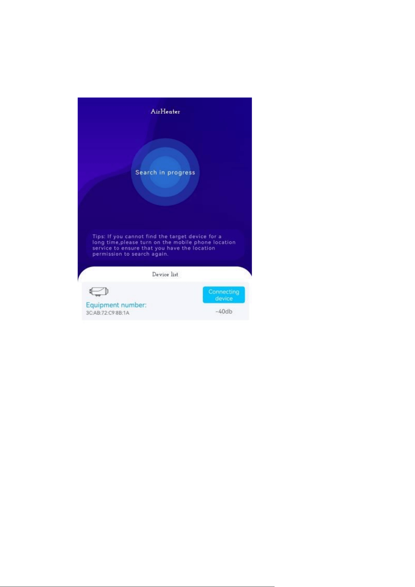
Bluetooth APP Usage Guide
1.Search Page
After the device is powered on, open the mobile phone APP to display the
following interface.
1.1 Figure 1 The icon indicates that the connected device is a heater.
1.2
Figure 2 Icons represent the unique device number for each machine.
1.3 The icon in Figure 3 indicates the connection status of the machine. If you
confirm the device you are currently using, click on the connected device
to enter the main interface.
1.4
The icon in Figure 4 indicates the signal strength of the switch equipped
with the machine. The lower the negative value, the higher the current
switch signal strength is, and it also indicates that the current switch is
closest to the user.
1.5 The icon in Figure 5 indicates that when the Bluetooth signal is unstable
and the device cannot be searched, short press Figure 5 to refresh the
signal.
Figure 1<=
Figure 2<=
=>Figure 3
=>Figure 4
=>Figure 5

2. Main interface
After the machine is successfully connected to the Bluetooth APP, the Bluetooth
APP displays the following interface.
2.1 Figure 1 icon shows the ambient temperature around the switch
2.2 Figure 2 indicates the temperature control mode of the machine; AT is automatic
temperature control <=> MT is manual temperature control
2.3 Figure 3 is unavailable
2.4 Figure 4 s hows the p ower supply voltage data, alt itude data,
fan s peed dat a, and m ac hine housing temperature data from
lef t t o right.
2.5 Figure 5 shows the set temperature display and the set gear display. The set
temperature range is adjusted in AT automatic temperature control mode, and
the range of 1-10 is adjusted in MT manual temperature control mode.
2.6 Figure 6 shows the Auto Start/Stop function, which illuminates when enabled.
The Auto Start/Stop function automatically turns on when the ambient
temperature is 2 degrees Celsius or higher below the set temperature and
automatically turns off when the ambient. The temperature is 1 degree Celsius or
higher above the set temperature.
When the Auto Start/Stop function is active, if the machine is off, Figure 11 will
display "Standby." The machine will automatically power on based on
temperature fluctuations. To completely shut down the machine, briefly press the
power button (Figure 8).Figure 11 will display "Power Off."
2.7 Figure 7 shows the time display of scheduled power on and off. If the scheduled
power on and off is not set, the displayed week is the real-time week of the day.
After setting the scheduled power on oroff, the time and week of the scheduled
power on or off will be displayed.
2.8 Figure 8 shows the power button, which lights up when the device is turned on
and turns off when the device is turned off.
2.9 Figure 9 is the down button, which is used to lower the set temperature or
working gear.
2.10 Figure 10 shows the upward adjustment button, which is used to increase the set
temperature or working gear.
2.11 Figure 11 shows the machine's working status.
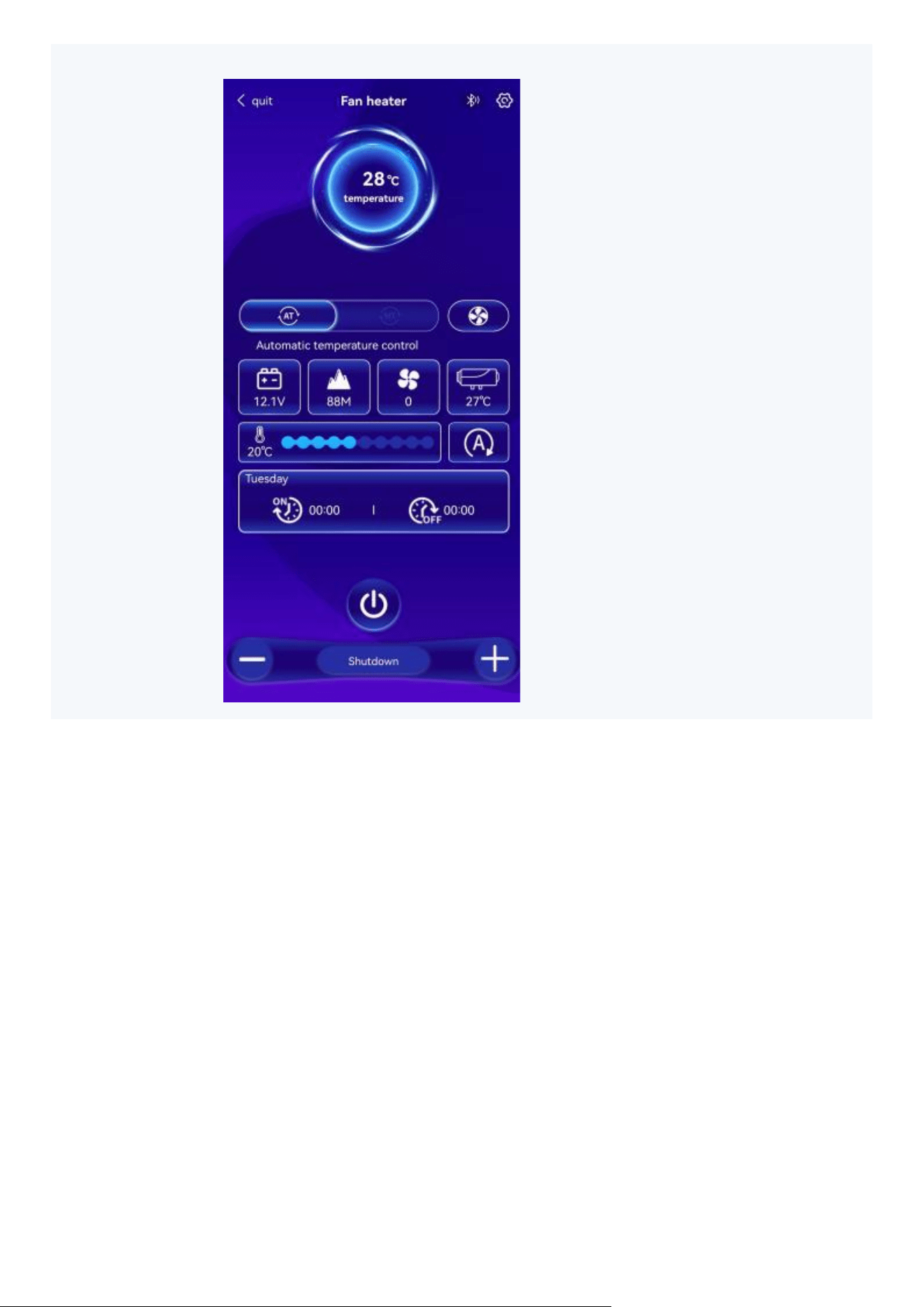
Figure 11
=> Figure 1
Figure 2<=
=>Figure 3
Figure 4<=
Figure 5<=
=>Figure 6
Figure 7<=
=> Figure 8
Figure 9<= =>Figure 10
1
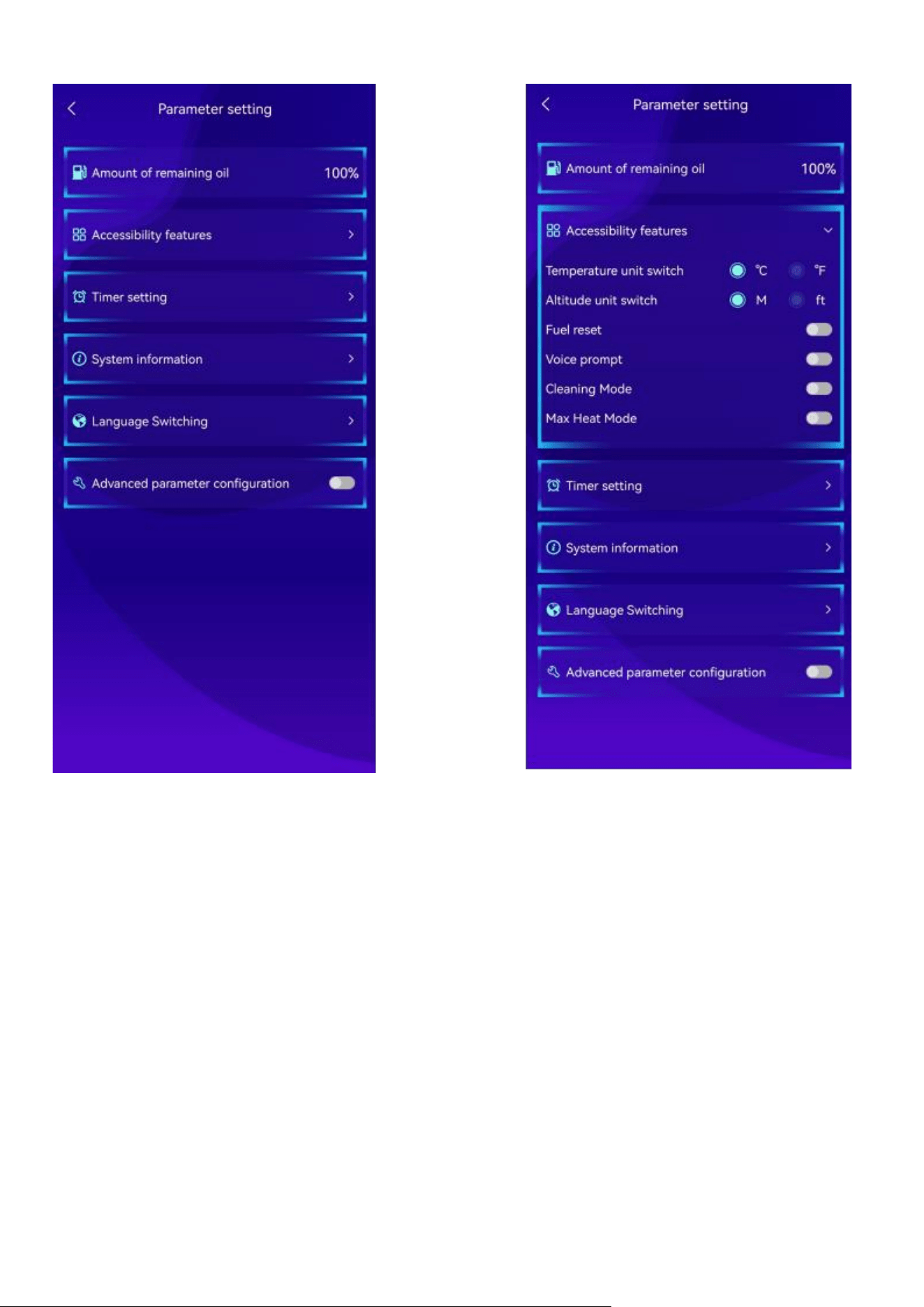
3.Parameter setting(Click the settings button in the upper right corner):
3.1 Figure 1 (Amount of remaining oil) is unavailable.
3.2 Accessibility features:
Figure 2—shows the temperature unit display switch. To display Celsius, select °
C. To display Fahrenheit, select ° F;
Figure 3-- shows the height unit switching setting. It without this function, it cannot
be switched.
Figure 4--This function (Fuel reset) is unavailable.
Figure 5--shows the voice prompt function. When it is turned on, there will be a
voice prompt when the machine is turned on. There will be no voice prompt when it
is turned off.
Figure 6-- This function (Cleaning Mode) is unavailable.
Figure 7-- shows the extreme heat mode. Once activated, the machine
automatically adjusts the air-to-fuel ratio, achieving high combustion efficiency and
temperatures in a short period of time.
Figure
Figure
Figure
Figure
Figure
Figure
2 <=
3 <=
4 <=
5 <=
6 <=
7 <=
=>Figure 1
1 1
2
3
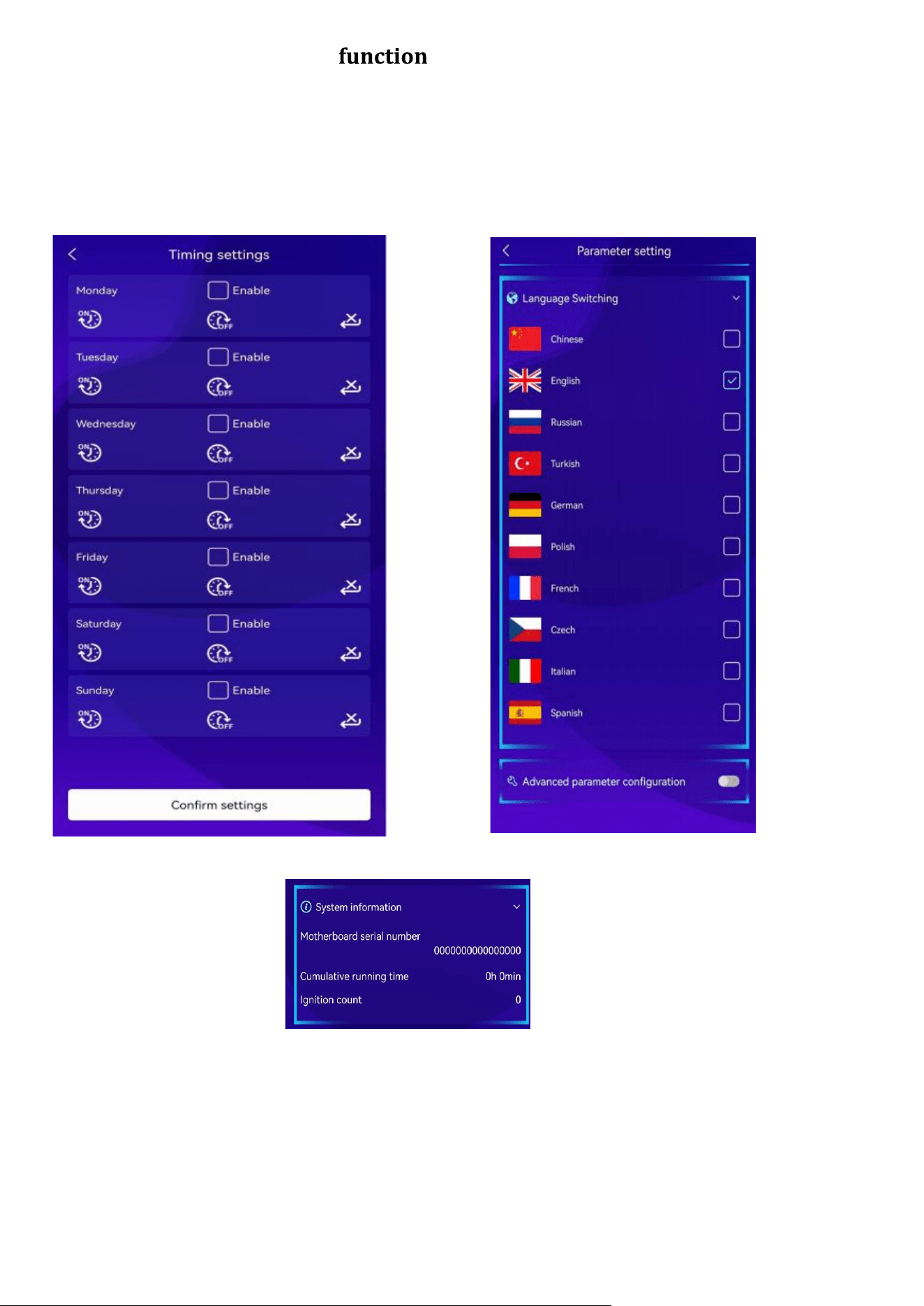
4.
Timer settings——This is not
available(Figure 4 below)
5. System information——This function is unavailable .(Figure 5 below)
6. language switch— After turning on the language switch, 10 languages and
their corresponding flags are displayed.Select the language you want to
switch to, and you can switch the language displayed on the APP with one
click.(Figure 6 below)
4 6
5
7.Advanced parameter settings(Figure 7 below):
7.1 Enter the four-digit password "9009" to enter the advanced parameter
configuration settings
7.2 Figure 1 shows the fuel type selection: This heater can only select diesel .
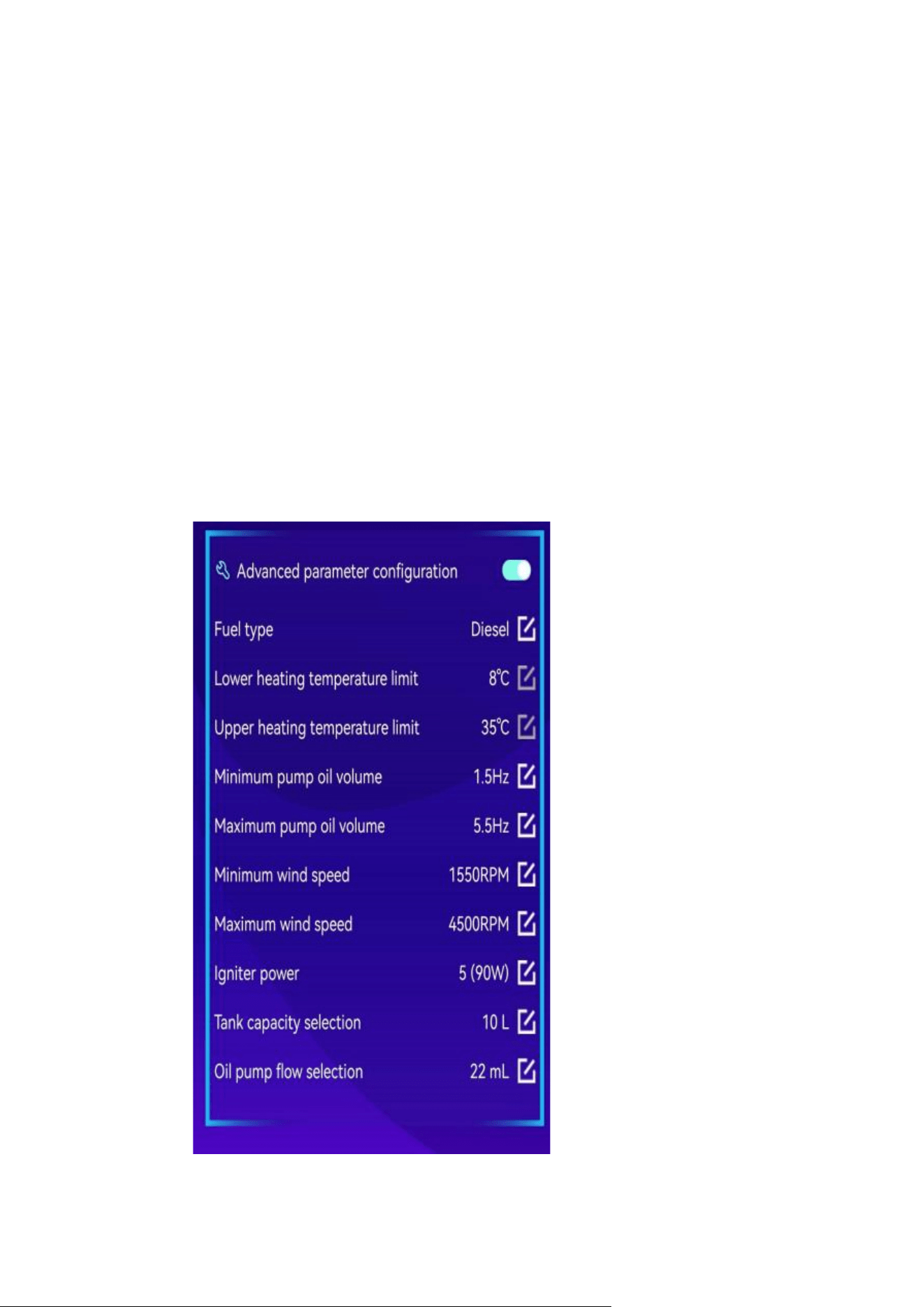
7.3 Figure 2 and Figure 3 are the lower and upper limits of the heating temperature.
Toensure the safe operation of the machine,they are temporarily closed and
cannot beset (This cannot be adjusted).
7.4 Figure 4 shows the minimum pump oil volume setting, which can be set within the
range of 0.8-3.5HZ
7.5 Figure 5 shows the maximum pump oil volume setting, which can be set
within the range of 2.5-9.0HZ
7.6 Figure 6 shows the minimum fan speed setting, which can be set from 1300-
3200RPM.
7.7 Figure 7 shows the maximum fan speed setting, which can be set from
3200-5000RPM.
7.8 Figure 8 shows the ignition power setting, which can be set from 70W to
95W.
7.9 Figure 9 shows the fuel tank capacity selection, which can be set in the
range of 5L-7L-9L-10L-15L-20L(No adjustment needed )
7.10 Figure 10 shows the oil pump flow selection, which can be set in the range
of 16ML-22ML-28ML-32ML(This heater isselected as 22ML).
、
=>Figure 1
=>Figure 2
=>Figure 3
=>Figure 4
=>Figure 5
=>Figure 6
=>Figure 7
=>Figure 8
=>Figure 9
=>Figure 10
7
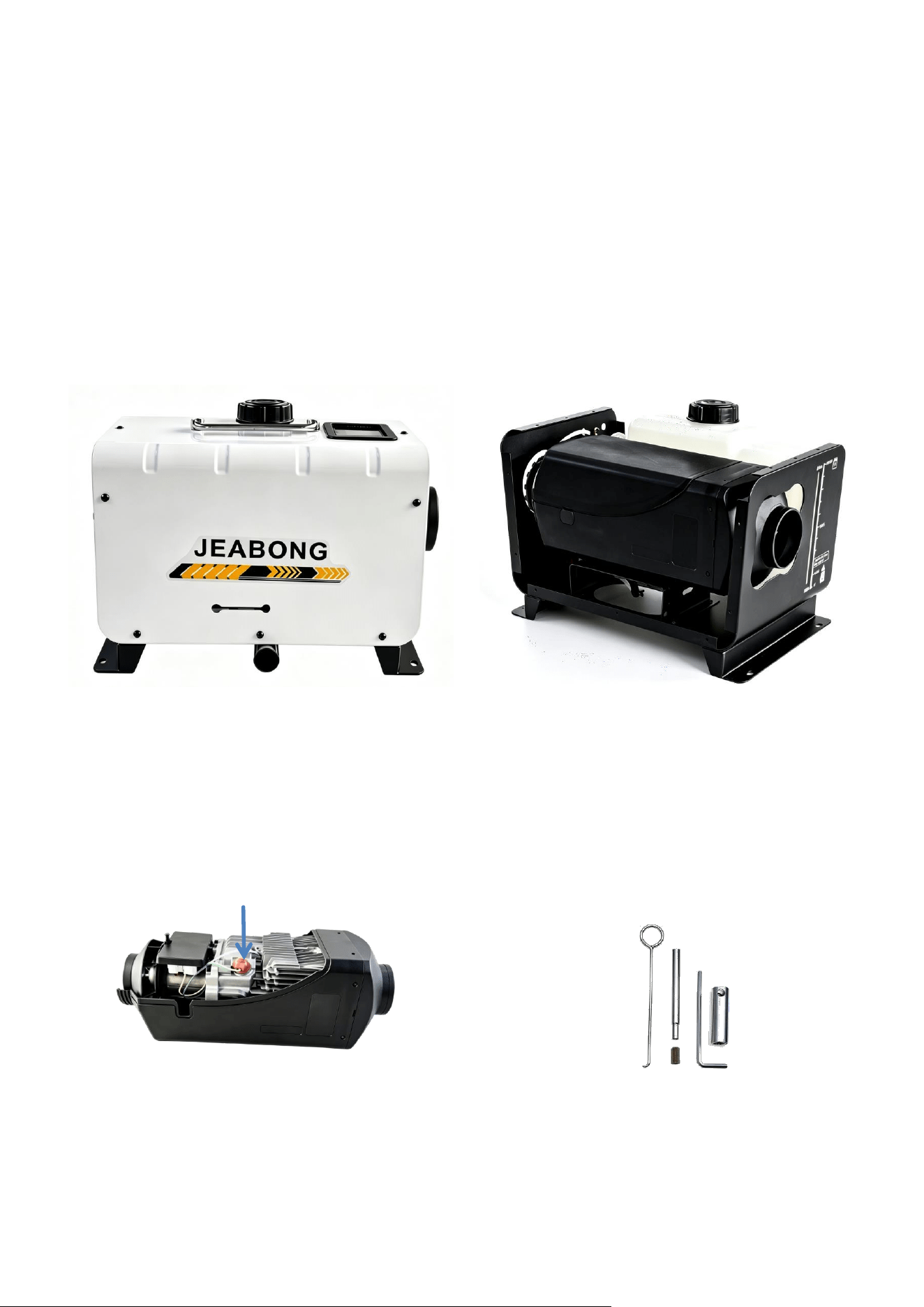
Maintenance diagram
Glow plug
Diesel Heater
Tool
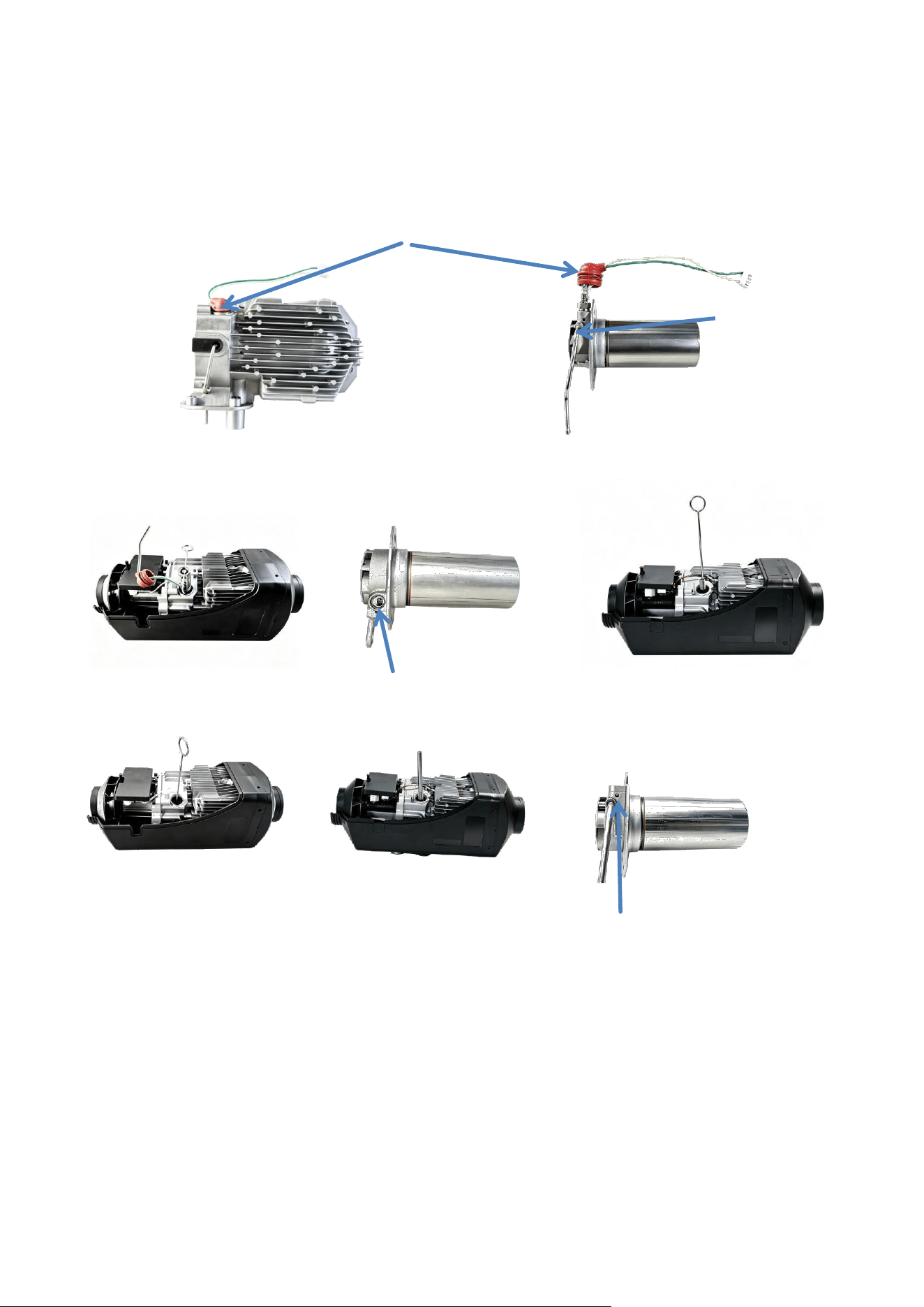
When installing the glow plug, pay attention to keeping the two wires of
the glow plug apart and not touching each other, and then fasten the
sealing cap
If E-08 appears after a period of use, please check if the fuel tank is
short of diesel and if there is diesel in the fuel pipe. If E-10 appears after
starting up and a large amount of white smoke is emitted from the
exhaust pipe, and E-10 still appears after starting up again, please
check if the combustion chamber inlet is blocked. If the air inlet is
unobstructed, please clean or replace the atomizing mesh.
Air inlet
The air inlet must be kept unobstructed
Glow plug
Remove the heating
plug
Location of atomizing mesh
Remove the atomizing mesh
Install atomizing mesh
Make the air inlet unobstructed
Make the air inlet unobstructed
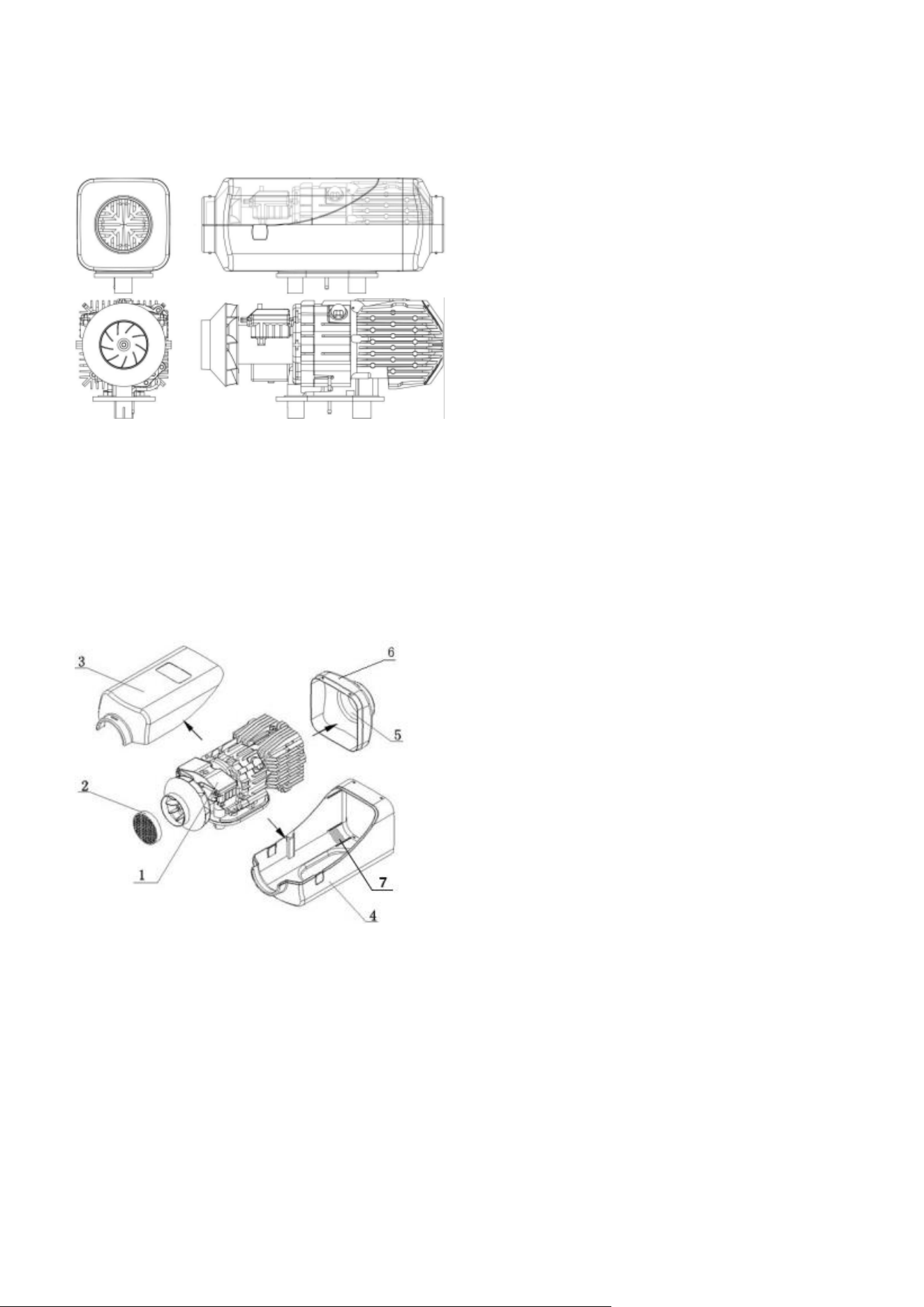
Host decomposition diagram
Structural Architecture 1
Structural Architecture 2
(1) Main engine
(2) Heating air intake grille
(3) Upper casing hood
(4) Lower casing hood
(5) Warm air vent
(6) Warm air vent hood
(7) High temperature resistant gasket ( Four pieces )
When disassembling or assembling the Main engine, pay attention to
placing the high-temperature resistant gaskets at the four corners of the
Main engine on the protruding parts of the four corners.
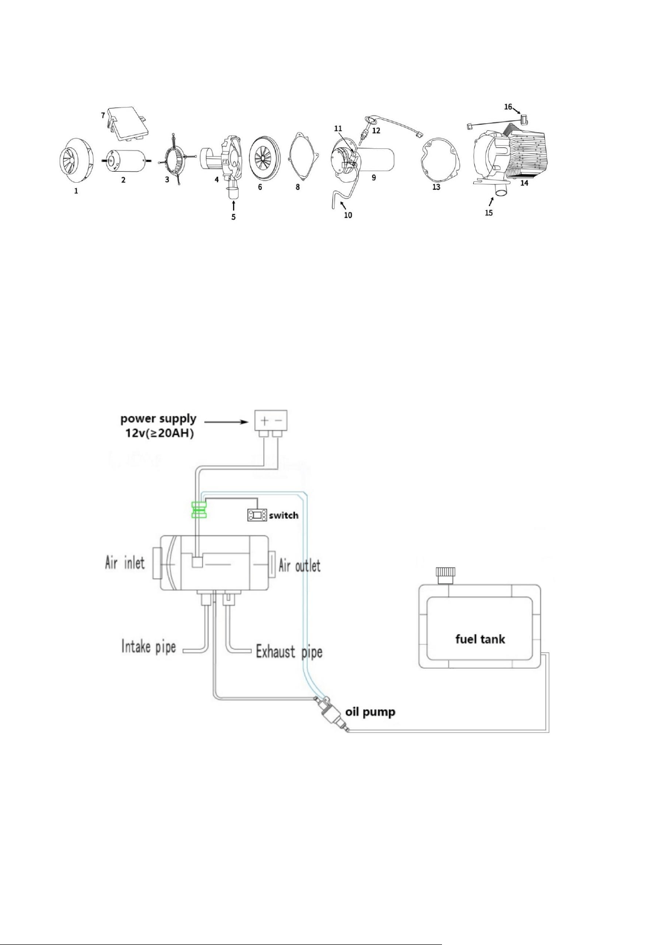
Structural Architecture 3
1 Heating fan 2 Fan motor 3 Bracket 4 Fan motor fixing bracket
5 Combustion air intake 6 Combustion fan 7 Controller 8、13 Gasket
9 Combustion chamber 10 Diesel fuel inlet pipe 11 Glow plug Mounting Hole 12 Glow plug
14 Aluminum body for heat dissipation 15 Exhaust vent 16 Temperature sensor
circuit diagram

Please let me know after receiving the goods, or if you encounter any problems during
use, please contact me. Video files can be received here.
Email: 2241757241@qq.com

FCC Warnning:
This equipment has been tested and found to comply with the limits for a Class B digital device,
pursuant to part 15 of the FCC Rules. These limits are designed to provide
reasonable
protection againstharmful interference in a residential installation. This equipment generates,
uses and can radiateradio
frequency
energy
and,
if
not
installed
and
used
in
accordance
with
the
instructions,
maycause
harmful
interference
to
radio
communications.
However,
there
is
no
guarantee
thatinterference
will
not
occur
in
a
particular
installation.
If
this
equipment
does
cause
harmfulinterference to radio or television reception, which can be
determined by turning the equipmentoff
and
on,
the
user
is
encouraged
to
try
to
correct
the
interference
by
one
or
more
of
thefollowing measures:
•
Reorient or relocate the receiving antenna.
•
Increase the separation between the equipment and receiver.
•
Connect the equipment into an outlet on a circuit different from that to which the receiver is
connected.
• Consult the dealer or an experienced radio/TV technician for help.
Caution:
Any
changes
or
modifications
to
this
device
not
explicitly
approved
by
manufacturer
could void your authority to operate this equipment.
This
device
complies
with
part
15
of
the
FCC
Rules.
Operation
is
subject
to
the
following
two
conditions:
(1)This
device
may
not
cause
harmful
interference,
and
(2)
this
device
must
accept
any
interference received, including interference that may cause undesired operation.
This
equipment
complies
with
FCC
radiation
exposure
limits
set
forth
for
an
uncontrolled
environment.
This
equipment
should
be
installed
and
operated
with
minimum
distance
20cm
between the radiator and your body.