
Wired Weekly Programmable
Wall-Mounted Controller
Installation and Owner’s Manual
MODEL:
TST-WPT-540L
Compatible With:
• WYT-20/24/25
• CYT-24
• UYT-24
• RYT-24
Product Series
IMPORTANT NOTE:
Please read this manual carefully
before installing or operating your
wired remote controller. Be sure to
save this manual for future reference.
REV250407

2
About This Manual
0
This manual provides important safety information and operating
instructions for the wired wall-mounted thermostat. To ensure
proper use and optimal performance, please read this manual
carefully before operating the unit.
For future reference, keep this manual in a safe and accessible
location.
Please note that the images included in this manual are for
illustrative purposes only. The appearance of your actual wired
controller may vary slightly depending on the specific model. In all
cases, the actual product takes precedence.
3
Table of Contents
1
1. Table of Contents ......................................................................................................... 3
2. Safety Precautions ...................................................................................................... 4
3. Installation Accessories .......................................................................................... 5
4. Installation Process ..................................................................................................... 7
5. Controller Overview ................................................................................................. 13
6. User Guide ...................................................................................................................... 18
7. Using the Timer Function ................................................................................... 22
8. Disposal Guidelines ................................................................................................ 25

4
Safety Precautions
2
⚠
WARNING
• Installation must be performed by the distributor or qualified professionals.
• Installation by untrained individuals may result in improper setup, electric
shock, or fire.
• Always follow the instructions in this manual.
• Incorrect installation can cause electric shock or fire.
• Reinstallation must also be carried out by professionals.
• Do not uninstall the unit arbitrarily.
Uninstalling the unit without proper procedures may lead to malfunction,
heating issues, or risk of fire in the air conditioning system.
ℹ
NOTE
• Do not install the unit in areas where flammable gases may leak.
Accumulation of such gases around the wired controller may result in fire.
• Do not operate the unit with wet hands or allow water to enter the wired
controller. Doing so may cause electric shock.
• Ensure the wiring is compatible with the current rating of the controller.
Mismatched wiring may cause electrical leakage, overheating, or fire. Use
only the specified cable types for wiring. Do not apply excessive force to
terminals. Doing so may damage the wires, leading to overheating or fire.
5
Installation Accessories
3
Selecting the Installation Location
Do not install the unit in locations exposed to heavy oil, steam, or
sulfur-containing gases. Exposure to such substances may deform the product
and cause system malfunction.
Preparation Before Installation
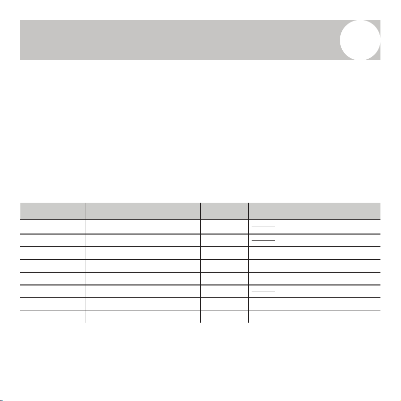
Before beginning installation, please confirm that all of the following
components have been provided:
Item Number Item Name Quantity Remarks
1 Wired Controller 1
2 Owner’s Manual 1
3 Mounting Screws 3 M3.5x25 (For Wall Mounting)
4 Wall Plugs 3 For Wall Mounting
5 Mounting Screws 2 M4x25 (For Switch Box)
6 Battery 1
7 Connection Wire Set 1 (Optional)
8 Mounting Screws 1 M4x8 (For Connecting Wire)
5
Installation Accessories
3
Selecting the Installation Location
Do not install the unit in locations exposed to heavy oil, steam, or
sulfur-containing gases. Exposure to such substances may deform the product
and cause system malfunction.
Preparation Before Installation
Before beginning installation, please confirm that all of the following
components have been provided:
Item Number Item Name Quantity Remarks
1 Wired Controller 1
2 Owner’s Manual 1
3 Mounting Screws 3 M3.5x25 (For Wall Mounting)
4 Wall Plugs 3 For Wall Mounting
5 Mounting Screws 2 M4x25 (For Switch Box)
6 Battery 1
7 Connection Wire Set 1 (Optional)
8 Mounting Screws 1 M4x8 (For Connecting Wire)
6
Installation Accessories
3
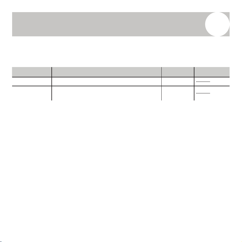
Prepare the following items on-site:
Precautions for Installing the Wired Controller
1. This manual provides instructions for installing the wired controller.
A. Refer to the wiring diagram within this manual for correct connection
of the wired controller to the indoor unit.
2. The wired controller operates in a low-voltage circuit.
A. Do not connect or route high-voltage cables (e.g., 115V, 220V, 380V)
within this loop.
B. Ensure a minimum separation distance of 12–20 in. (or more) between
low-voltage and high-voltage wiring.
3. The shielded wire of the wired controller must be properly grounded.
4. After completing the wiring connection, do not use a megohmmeter
(insulation resistance tester) to test the insulation, as this may damage the
controller.
Item Number Item Name Quantity Remarks
1 Switch Box 1
2
Wiring Tube (with Insulating Sleeve and
Tightening Screw)
1
6
Installation Accessories
3
Prepare the following items on-site:
Precautions for Installing the Wired Controller
1. This manual provides instructions for installing the wired controller.
A. Refer to the wiring diagram within this manual for correct connection
of the wired controller to the indoor unit.
2. The wired controller operates in a low-voltage circuit.
A. Do not connect or route high-voltage cables (e.g., 115V, 220V, 380V)
within this loop.
B. Ensure a minimum separation distance of 12–20 in. (or more) between
low-voltage and high-voltage wiring.
3. The shielded wire of the wired controller must be properly grounded.
4. After completing the wiring connection, do not use a megohmmeter
(insulation resistance tester) to test the insulation, as this may damage the
controller.
Item Number Item Name Quantity Remarks
1 Switch Box 1
2
Wiring Tube (with Insulating Sleeve and
Tightening Screw)
1
7
Installation Process
4
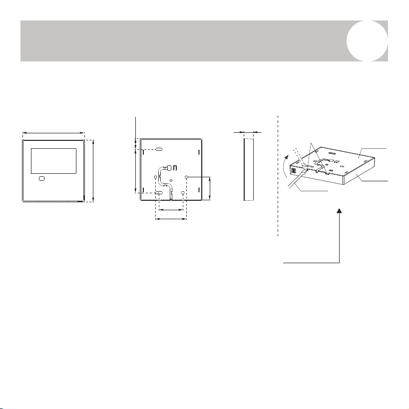
Wired Remote Controller – Structural Dimensions
Refer to the diagram below for the physical dimensions of the wired controller.
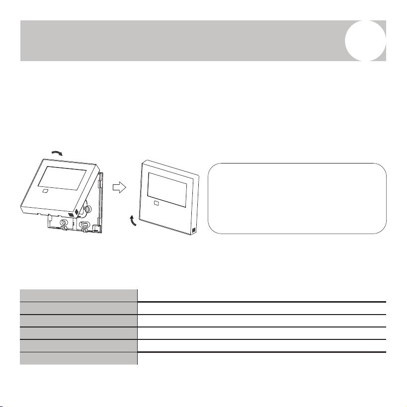
Removing the Upper Cover of the Wired Controller
To access the internal wiring and mounting screws:
• Insert a flat-head screwdriver into the two slots located at the bottom of
the wired controller.
• Carefully release the clips to detach and lift off the front cover (Fig. 3-2).
Note: Take care not to apply excessive force when prying open the casing to
avoid damaging the plastic components.
4-3/4”
Front View Side ViewRear View
3/4”
13/16”
4-3/4”
3-5/16”
1-13/16”
2-3/8”
1-3/4”
Rear cover
Flat head
screwdriver
Buckling
position
Front cover
Fig. 3-1 Fig. 3-2
8
Installation Process
4
Note: The PCB (Printed Circuit Board) is located in the upper section of the
controller. Use caution when using a screwdriver to avoid damaging the board.
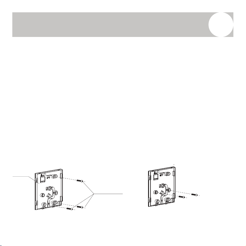
Fasten the Back Plate of the Wired Controller
• For exposed wall mounting:
- Use three screws (M3.5 × 25) and corresponding wall plugs to secure
the back plate directly to the wall surface.
- Refer to Fig. 3-3 for proper screw placement.
• For mounting on a standard 86 switch box:
- Use two M4 × 25 screws to secure the back plate to the switch box.
- Use an additional M4 × 25 screw to anchor the back plate to the wall
for added stability.
- Refer to Fig. 3-4 for guidance.
Fig 3-3
Back plate
Screws(M3.5×25)
Fig 3-4
Screws hole installed on
switch box, use two M4×25mm
9
Installation Process
4
Note: Place the wired controller on a flat surface during installation. Avoid
overtightening the mounting screws, as it may distort/damage the back plate.
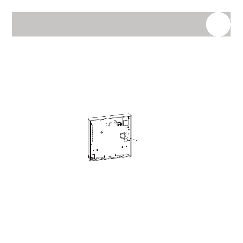
Battery Installation
Insert the battery into the designated battery compartment, ensuring the
positive (+) side of the battery aligns with the positive terminal in the
compartment (see Fig. 3-5).
Upon first-time use, set the correct time on the controller. The internal battery
allows the controller to retain the clock settings during power outages.
If, after power is restored, the displayed time is incorrect, it indicates that the
battery has failed and should be replaced.
Fig 3-5
Battery
Insertion Point
8
Installation Process
4
Note: The PCB (Printed Circuit Board) is located in the upper section of the
controller. Use caution when using a screwdriver to avoid damaging the board.
Fasten the Back Plate of the Wired Controller
• For exposed wall mounting:
- Use three screws (M3.5 × 25) and corresponding wall plugs to secure
the back plate directly to the wall surface.
- Refer to Fig. 3-3 for proper screw placement.
• For mounting on a standard 86 switch box:
- Use two M4 × 25 screws to secure the back plate to the switch box.
- Use an additional M4 × 25 screw to anchor the back plate to the wall
for added stability.
- Refer to Fig. 3-4 for guidance.
Fig 3-3
Back plate
Screws(M3.5×25)
Fig 3-4
Screws hole installed on
switch box, use two M4×25mm
9
Installation Process
4
Note: Place the wired controller on a flat surface during installation. Avoid
overtightening the mounting screws, as it may distort/damage the back plate.
Battery Installation
Insert the battery into the designated battery compartment, ensuring the
positive (+) side of the battery aligns with the positive terminal in the
compartment (see Fig. 3-5).
Upon first-time use, set the correct time on the controller. The internal battery
allows the controller to retain the clock settings during power outages.
If, after power is restored, the displayed time is incorrect, it indicates that the
battery has failed and should be replaced.
Fig 3-5
Battery
Insertion Point
10
Installation Process
4
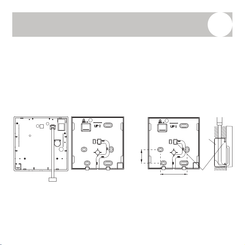
Refer to Figures 3-6 and 3-7 for proper wiring layout.
• Connect the wired controller to the indoor unit using the designated
terminal port as shown in Fig. 3-6.
• Create a notch in the back plate or switch box to allow the wiring to pass
through. Use wire cutters/snippers for a clean and accurate cut (Fig. 3-7).
Fig 3-6
1-3/4”
2-3/8”
wiring hole
switch box
Fig 3-7
Note:
• Do not allow water or moisture to enter the remote controller during or after installation.
• Use sealing materials such as putty and drip traps to seal around the wire entry points
and prevent water intrusion.
10
Installation Process
4
Refer to Figures 3-6 and 3-7 for proper wiring layout.
• Connect the wired controller to the indoor unit using the designated
terminal port as shown in Fig. 3-6.
• Create a notch in the back plate or switch box to allow the wiring to pass
through. Use wire cutters/snippers for a clean and accurate cut (Fig. 3-7).
Fig 3-6
1-3/4”
2-3/8”
wiring hole
switch box
Fig 3-7
Note:
• Do not allow water or moisture to enter the remote controller during or after installation.
• Use sealing materials such as putty and drip traps to seal around the wire entry points
and prevent water intrusion.
11
Installation Process
4
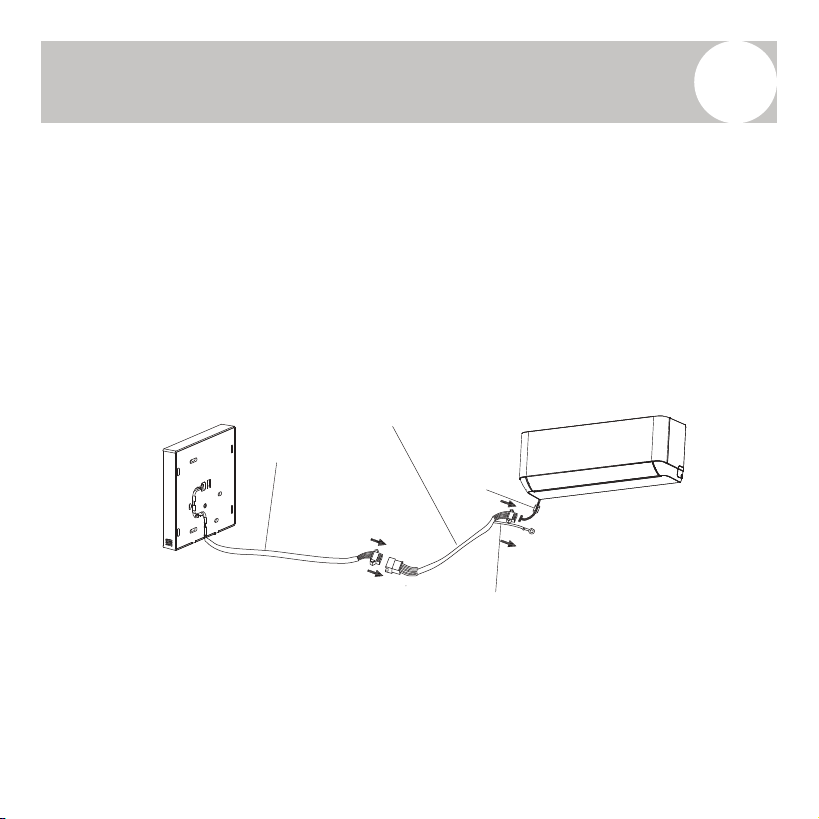
Connect the wire from the master control board of the indoor unit to the
connection cable. Then, connect the other end of the cable to the wired remote
controller, as shown in Fig. 3-8.
• Use a 4-conductor wire for communication.
• The connective wiring harness should include a magnetic ring to help
suppress electrical interference.
• Use shielded wire to reduce signal noise and ensure stable operation.
Note:
• Leave sufficient slack in the connective wire to allow for future maintenance or service.
• At the end of the shielded wire, there is a grounding lug. Ensure this lug is properly
connected to a reliable ground point to maintain electrical safety and signal integrity.
Fig. 3-8
Connective Wiring Harness
Shielded Wire
4-Conductor Wire
Magnetic
Ring
12
Installation Process
4
Reattach the Upper Cover of the Wired Controller
• Align the upper cover and snap it securely back into place.
• Ensure that no wires are pinched or obstructed during reassembly. (See
Fig. 3-9)
Specifications
Fig 3-9
The illustrations in this manual are for
reference only. The actual appearance of
your wired controller may vary
depending on the model. In all cases, the
actual product shall take precedence.
Input Voltage
DC 5V / 12V
Operating Temperature
23°F to 110°F (-5°C to 43°C)
Operating Humidity
40% RH to 90% RH
Wiring Type
Shielded Control Cable
Wiring Size
20–16 AWG
Total Wiring Length
≤ 164 ft (50 m)
13
Controller Overview
5
Controller Features
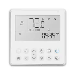
• LCD Display: Clear and intuitive display of
system status and settings.
• Error Code Display: Automatically shows
malfunction codes to aid in diagnostics and
service.
• 4-Way Wire Entry Design: Wiring can be
routed from any side of the back panel (top,
bottom, left, or right), with a flat back cover
for easy wall installation.
• Room Temperature Display: Real-time
indoor temperature monitoring.
• Weekly Timer: Program customized on/off
schedules for daily and weekly operation.
• Mode Selection: Auto/Cool/Dry/Heat/Fan Only/Turbo
• Fan Speed Options: Mute / Auto / Low / Medium-Low
/ Medium / Medium-High / High
• Swing Function (on some models): Enables
motorized movement of the louver for direction control.
• Timer ON/OFF: Set automatic start and stop times.
• Temperature Setting: Adjust the desired room temp.
• Weekly Timer: Customize operation schedules for each
day of the week.
• Follow Me: Uses the remote’s internal sensor to
regulate temperature near the user. (If enabled)
• Time Display Options: 24-hour or 12-hour format
• Turbo Mode: Enables rapid heating or cooling.
• Auto-Restart (on some models): Automatically
resumes operation after power failure.
• Child Lock: Locks controller to prevent unintended use.
• Individual Louver Control (on some models): Allows
separate control of each air outlet's direction.
• Clock Display: Built-in clock for time-related functions.
• Automatic Airflow Test: System function to verify
proper airflow performance.
• Panel Function (on some models): Additional controls
available directly from the indoor unit panel.
Controller Functions
14
Controller Overview
5
1 2 3 4 5
6
7
8911
1213
14
15
16
17
10
Refer to Page 15 for the explanation of each icon.
15
Controller Overview
5
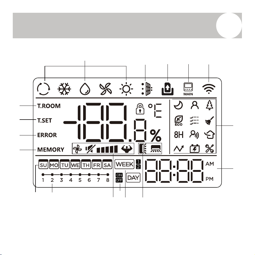
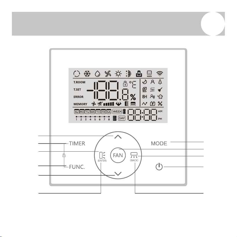
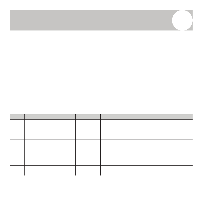
No. Icon / Indicator Description
1 Mode
Displays the current operating mode.
(Auto, Cool, Dry, Heat, Fan).
2 Dust Full
Indicates full dust bin.
(on compatible models with filtration/cleaning systems)
3 Door Card
Shown when door card access is linked.
(typically for hotel applications).
4 Main IDU Indicates control over the main indoor unit.
5 Wi-Fi Lit when Wi-Fi connection is active.
6 Function Icons
Miscellaneous feature icons.
(e.g., Eco Mode, Turbo, Child Lock, Maintenance)
7 Clock Shows the current time (12/24-hour format).
8 Swing Indicates swing mode is active.
9 Week Timer Active when weekly timer scheduling is in use.
10 Timer ON/OFF Shows programmed timer
status.
11 Fan Speed Displays selected fan speed level.
12 Timer Task Indicates scheduled timer tasks are set.
13 Week Day-of-week display (SU–SA).
14 Power-Down Memory Indicates settings memory is active after power loss.
15 Error Displays error codes when a fault occurs.
16 Temperature Setting (T.SET) Shows the user-set temperature.
17 Room Temperature (T.ROOM) Displays the current room temperature.
Explanation of Controller Display Icons Depicted on Page 14:
14
Controller Overview
5
1 2 3 4 5
6
7
8911
1213
14
15
16
17
10
Refer to Page 15 for the explanation of each icon.
15
Controller Overview
5
No. Icon / Indicator Description
1 Mode
Displays the current operating mode.
(Auto, Cool, Dry, Heat, Fan).
2 Dust Full
Indicates full dust bin.
(on compatible models with filtration/cleaning systems)
3 Door Card
Shown when door card access is linked.
(typically for hotel applications).
4 Main IDU Indicates control over the main indoor unit.
5 Wi-Fi Lit when Wi-Fi connection is active.
6 Function Icons
Miscellaneous feature icons.
(e.g., Eco Mode, Turbo, Child Lock, Maintenance)
7 Clock Shows the current time (12/24-hour format).
8 Swing Indicates swing mode is active.
9 Week Timer Active when weekly timer scheduling is in use.
10 Timer ON/OFF Shows programmed timer st
atus.
11 Fan Speed Displays selected fan speed level.
12 Timer Task Indicates scheduled timer tasks are set.
13 Week Day-of-week display (SU–SA).
14 Power-Down Memory Indicates settings memory is active after power loss.
15 Error Displays error codes when a fault occurs.
16 Temperature Setting (T.SET) Shows the user-set temperature.
17 Room Temperature (T.ROOM) Displays the current room temperature.
Explanation of Controller Display Icons Depicted on Page 14:
16
Controller Overview
5
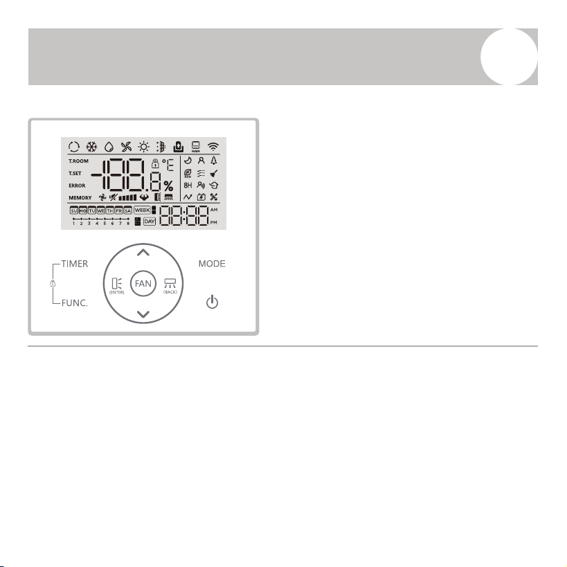
Refer to Page 17 for the overview of each button.
1
2
3
4
5
6
7
8
9
10
11
16
Controller Overview
5
Refer to Page 17 for the overview of each button.
1
2
3
4
5
6
7
8
9
10
11
17
Controller Overview
5
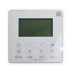
No. Button Overview
1 [UP] Adjusts temperature, time, or menu settings upward.
2 [TIMER]
Accesses the timer setup menu for ON/OFF
scheduling.
3 [UP-DOWN SWING] Activates vertical louver movement (if available).
4 [FUNC.] (Function)
Opens the function menu for advanced settings and
features.
5 [DOWN]
Adjusts temperature, time, or menu settings
downward.
6 [ENTER] Confirms selections within menus or settings.
7 [MODE]
Cycles through operating modes: Auto, Cool, Dry,
Heat, Fan Only.
8 [FAN SPEED] Selects desired fan speed level.
9 [LEFT-RIGHT SWING]
Activates horizontal louver movement (on compatible
models).
10 [ON/OFF] Powers the unit on or off.
11 [BACK
]
Returns to the previous screen or exits current
setting mode.
Overview of Controller Buttons Depicted on Page 16:
18
User Guide
6
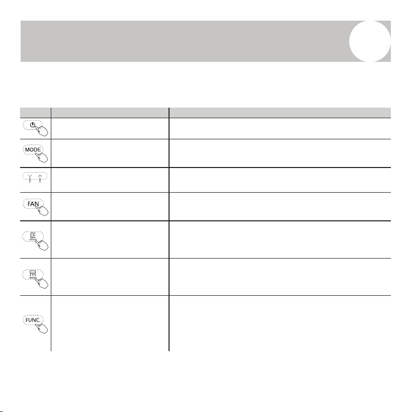
Explanation of Controller Buttons and Their Corresponding Functions:
Button Button Name Function Explanation
[ON/OFF] Button Press the power button to turn the air conditioner on or off.
[MODE]
Press the MODE button to cycle through the available operating
modes:
AUTO → COOL → DRY → FAN → HEAT
[▲ UP / ▼ DOWN]
• Press ▲ to increase the set temperature or adjust time values.
• Press ▼ to decrease the set temperature or adjust time values.
[FAN SPEED]
Press the FAN button to cycle through fan speed settings:
Mute → Low → Medium-Low → Medium → Medium-High
→ High → Turbo → Auto Speed
[UP-DOWN SWING] / [ENTER]
Press this button (ENTER) to toggle the vertical (up-down) swing
function.
When navigating settings, press this button to confirm your
selection.
[LEFT-RIGHT SWING] / [BACK]
Press this but
ton (BACK) to toggle the horizontal (left-right)
swing function.
When navigating settings, press this button to return to the
previous menu.
[FUNCTION]
Press the FUNC button to enter function selection mode.
• The currently selected function icon will blink.
• Use the ▲ / ▼ buttons to scroll through the available functions.
• If the icon remains lit, the function is active.
• If the icon turns off, the function is inactive.
Lower Raise
18
User Guide
6
Explanation of Controller Buttons and Their Corresponding Functions:
Button Button Name Function Explanation
[ON/OFF] Button Press the power button to turn the air conditioner on or off.
[MODE]
Press the MODE button to cycle through the available operating
modes:
AUTO → COOL → DRY → FAN → HEAT
[▲ UP / ▼ DOWN]
• Press ▲ to increase the set temperature or adjust time values.
• Press ▼ to decrease the set temperature or adjust time values.
[FAN SPEED]
Press the FAN button to cycle through fan speed settings:
Mute → Low → Medium-Low → Medium → Medium-High
→ High → Turbo → Auto Speed
[UP-DOWN SWING] / [ENTER]
Press this button (ENTER) to toggle the vertical (up-down) swing
function.
When navigating settings, press this button to confirm your
selection.
[LEFT-RIGHT SWING] / [BACK]
Press thi
s button (BACK) to toggle the horizontal (left-right)
swing function.
When navigating settings, press this button to return to the
previous menu.
[FUNCTION]
Press the FUNC button to enter function selection mode.
• The currently selected function icon will blink.
• Use the ▲ / ▼ buttons to scroll through the available functions.
• If the icon remains lit, the function is active.
• If the icon turns off, the function is inactive.
Lower Raise
19
User Guide
6
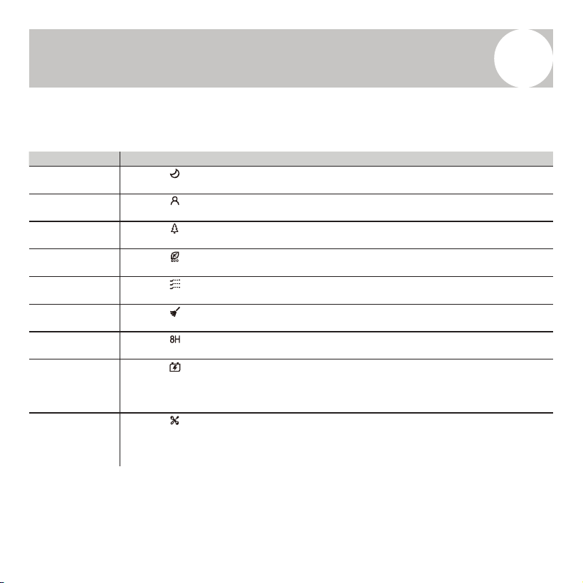
Explanation of Additional Functions (Activated with FUNC. Button):
Button Name Function Explanation
SLEEP Mode
When the icon blinks, press ENTER to toggle the Sleep Mode, which adjusts
temperature automatically for nighttime comfort.
I FEEL Function
When the icon blinks, press ENTER to toggle the I Feel function, using the remote’s
built-in temperature sensor for precise control near the user.
HEALTH Mode
When the icon blinks, press ENTER to activate or deactivate the Health Mode, which
may include ionization or air purification features (depending on model).
ECO Mode
When the icon blinks, press ENTER to enable or disable Energy-Saving Mode for
reduced power consumption.
GENTLE Airflow
When the icon blinks, press ENTER to toggle Gentle Mode, which softens airflow for a
quieter, mo
re comfortable breeze.
SELF-CLEANING
When the icon blinks, press ENTER to activate or deactivate the Self-Cleaning function
(only when the unit is powered off).
8H Mode
When the icon blinks, press ENTER to toggle the 8-hour heating mode, typically used
for minimal background heating.
GENERATOR
Mode
When the icon blinks, press ENTER to open the Generator Gear Selection interface:
• Use ▲ / ▼ to scroll through gear levels: OF → L1 → L2 → L3.
• Press ENTER to confirm your selection. The chosen gear will remain lit.
• Selecting OF disables the generator mode, and the icon will disappear.
PARAMETER
SETTING
When the icon blinks, press ENTER to access the Parameter Setting interface.
• The timer zone will begin blinking.
• The controller will display the cu
rrent device function code.
• The temperature setting area will show the corresponding parameter value.
20
User Guide
6
Parameter Setting
You can change device function settings using the ▲ / ▼ buttons to scroll
through function codes.
• Press ENTER to select a function code and access its parameter.
• The temp. display zone will then blink and show current parameter value.
• Use ▲ / ▼ again to adjust the parameter.
• Press ENTER to confirm your selection.
• Press the Power button to exit the parameter setting mode.
Code Function Parameter Description
P6 Fahrenheit/Celsius Display F / C F = °F display, C = °C display
PA
Ambient / Set Temperature
Display
00 / 01 00 = Show Set Temp, 01 = Show Ambient Temp
PD
Buzzer (Button Sound)
On/Off
ON / OFF Toggle button press sound
A8
Maximum Backlight
Brightness (%)
30 – 100 Set the brightness level (as a percentage)
B3 Dust Full Reminder ON / OFF Enable or disable dust filter reminder (if supported)
B4 Clock Display Format 12 / 24 12 = 12-hour, 24 = 24-hour time format

21
User Guide
6
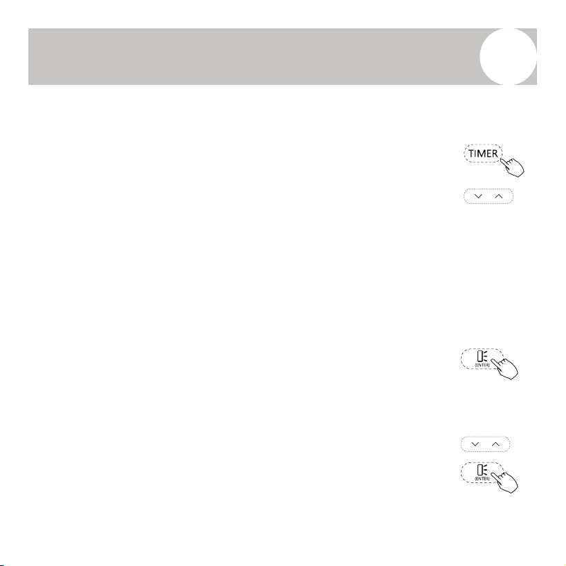
Real-Time Clock Setting
To manually set the day and time:
1. Press and hold the TIMER button for more than 2 seconds.
- The timer zone will blink and the day of the week will appear.
2. Use the ▲ / ▼ buttons to select day of the week, then ENTER to confirm.
3. The hour will begin blinking. Use ▲ / ▼ to adjust the hour, then press ENTER to confirm.
4. The minutes will then blink. Use ▲ / ▼ to adjust the minute value, and ENTER to confirm.
5. To quickly adjust any value, press and hold the ▲ or ▼ buttons.
Note: If the controller is connected to Wi-Fi, the current time will be automatically synced—manual
setup is not necessary.
Auxiliary Functions
• Child Lock
◦ To activate or deactivate the child lock, press and hold both the FUNC. and TIMER
buttons for more than 3 seconds.
◦ Once activated, the lock icon will remain lit.
• Wi-Fi Reset
◦ To reset the Wi-Fi network, press and hold both the MODE and ▲ buttons for more than
3 seconds.
◦ This will allow the unit to reconnect or join a new Wi-Fi network.
22
Using the Timer Function
7
Selecting a Timer Function
• Press the TIMER button to enter the timer function selection menu.
• Use the ▲ / ▼ buttons to cycle through available timer types.
• The selected timer mode will blink on the display.
Available Timer Modes:
• TIMER ON – Automatically powers the system on at a set time.
• TIMER OFF – Automatically powers the system off at a set time.
• WEEK TIMER 1 – Allows up to 8 on/off tasks per week.
• WEEK TIMER 2 – Same as WEEK TIMER 1, with additional options
to set operating mode, temperature, and fan speed.
Press the ENTER button to confirm your selection and access the timer
setup screen.
TIMER ON/OFF Function Setup
1. After selecting TIMER ON/TIMER OFF, timer zone begins blinking.
2. Use ▲ / ▼ to set the hour, then press ENTER to confirm.
3. Use ▲ / ▼ to set the minutes, then press ENTER again to confirm
and exit the timer setup.
23
Using the Timer Function
7
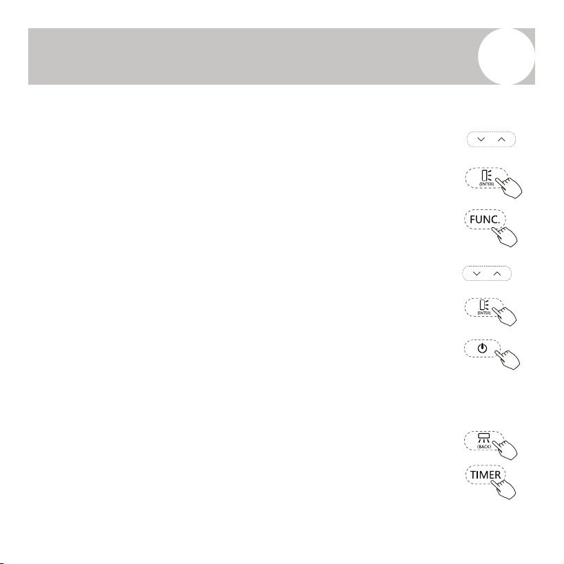
WEEK TIMER 1 Setup
WEEK TIMER 1 allows scheduling up to 8 timed tasks per week.
1. After selecting WEEK TIMER 1, the task icon will blink.
2. Use ▲ / ▼ to select a task (1 to 8). Press ENTER to confirm.
3. Use ▲ / ▼ to choose the day of the week (Sunday to Saturday).
• Press FUNC. to toggle the timer between ON and OFF status.
• If the display shows "ON", the date setting is valid. If it shows
"OFF", press FUNC. again to retry.
• Press ENTER to confirm.
4. Use ▲ / ▼ to toggle between Day On and Day Off for that
schedule. Press ENTER to confirm.
5. Set the hour with ▲ / ▼, then press ENTER.
6. Set the minute, then press ENTER.
7. Repeat steps 2–6 for additional timer tasks.
8. Press the Power button to exit the timer setup.
NOTES:
• Press BACK to return to the previous menu.
• To clear the entire WEEK TIMER 1 settings, press and hold TIMER
for over 2 seconds while on Step 1.
• To clear only the current task’s setting, press and hold TIMER
during Step 2 for more than 2 seconds.
24
Using the Timer Function
7
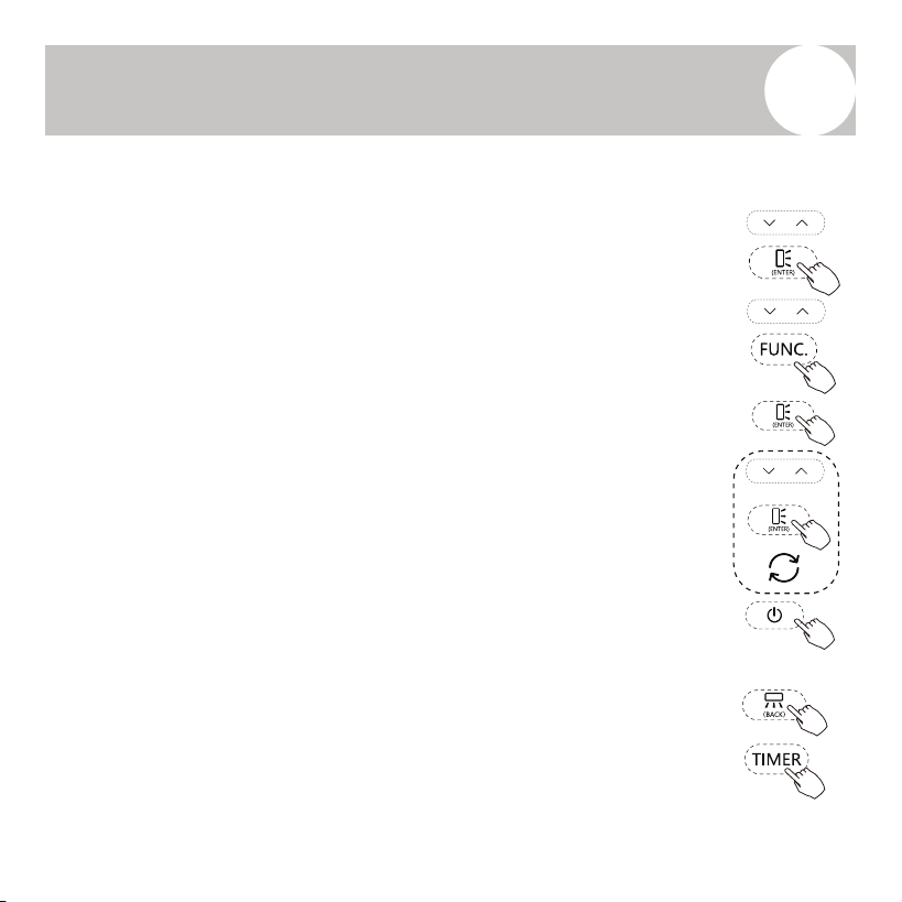
WEEK TIMER 2 Setup
WEEK TIMER 2 adds advanced controls to each timer task, including mode,
temperature, and fan speed.
1. After selecting WEEK TIMER 2, the task icon will blink.
2. Use ▲ / ▼ to choose a task (1 to 8), then press ENTER to confirm.
3. Select the day of the week with ▲ / ▼, then press FUNC. to toggle between
"ON" and "OFF".
• If the display shows "ON", the current setting is active.
• If "OFF", press FUNC. again and then ENTER to confirm.
4. Choose between Day On and Day Off using ▲ / ▼, then press ENTER.
• If set to Day On, continue to set:
◦ Operating Mode: Use ▲ / ▼ to select, then press ENTER.
◦ Temperature: Use ▲ / ▼ to adjust, then press ENTER.
◦ Fan Speed: Use ▲ / ▼ to select, then press ENTER.
• If set to Day Off, skip directly to Step 5.
5. Set the hour using ▲ / ▼, then press ENTER.
6. Set the minute, then press ENTER.
7. Repeat steps 2–6 for other tasks.
8. Press the Power button to exit the timer menu.
NOTES:
• Press BACK to return to the previous menu.
• To clear all WEEK TIMER 2 settings, press and hold TIMER for more than 2
seconds at Step 1.
• To clear a specific task, press and hold TIMER at Step 2 for more than 2
seconds.
25
Disposal Guidelines
8
This wired controller contains electronic components that may pose
environmental hazards if not properly disposed of. Do not discard this device
as general household waste or in unsorted municipal waste streams.
When disposing of the controller, please follow these guidelines:
• Dispose of the device at a certified electronic waste collection facility in
accordance with local laws and regulations.
• When purchasing a replacement product, some retailers may offer free
take-back of the old device.
• The manufacturer or authorized service center may also accept the unit
for safe disposal at no additional cost.
• Alternatively, the controller may be delivered to a certified e-waste
recycler or scrap electronics dealer.
Improper disposal, such as discarding the
controller in forests or natural environments, can
be harmful to human health and the ecosystem.
Hazardous substances from electronic
components may contaminate soil and
groundwater.

The design and specifications of this product are subject to change without prior notice
as development continues. Consult with the sales agency or manufacturer for details.
Refer to the equipment for all other applicable specifications.
Copyright 2025, Parker Davis HVAC International, LLC., All rights reserved.
is a registered trademark of Parker Davis HVAC International, LLC.
Parker Davis HVAC International
7290 NW 77 Court, Miami, FL 33166 - USA
Tel
: (305) 513-4488
Fax
: (305) 513-4499
E-mail
Website: www.pdhvac.com
Pioneer product line, parts, and supplies are
available online for convenient ordering at:
www.highseer.com
www.pioneerminisplit.com
Scan the below code to visit our support page
where you can find more installation materials: