Installation and Owner’s Manual
WIRED REMOTE CONTROLLER
MODEL:
TST-IRW-120N
IMPORTANT NOTE:
Please read this manual carefully
before installing or operating your
wired remote controller. Make sure to
save this manual for future reference.

This manual gives detailed description of the precautions
that should be brought to your attention during operation.
In order to ensure correct service of the wired controller
please read this manual carefully before using the unit.
For convenience of future reference, keep this manual
after reading it.
All the pictures in this manual are for explanation purpose
only. There may be slightly dierent from the wired remote
controller you purchased (depend on model). The actual
shape shall prevail.

1. Safety precaution
2. Installation accessory
3. Installation method
4. Specification
5. Feature and function of the wired controller
6. Name on the LCD of the wired controller
7. Name of button on the wired controller
8. Preparatory operation
9. Operation
10. Timer functions
11. Weekly Timer 1
12. Weekly Timer 2
13. Fault alarm handing
14.Technical indication and requirement
15.Queries and settings
16. Wireless control connection
..........................................................1
................................................... 2
........................................................4
................................................................16
................17
.....................18
......................19
.................................................20
....................................................................21
...........................................................31
..........................................................34
.........................................................40
..................................................47
........................47
..................................................48
.......................................53
Table of Contents
1
1. Safety precaution
Do not uninstall the unit randomly.
Random uninstalling may lead to abnormal operation,
heating or re of the air condition.
WARNING
Please entrust the distributor or professionals to install the unit.
Installation by other persons may lead to imperfect installation,
electric shock or re.
Adhere to this installation manual.
Imporper installation may lead to electric shock or re.
Reinstallation must be performed by professionals.
•
•
•
•
•
NOTE
Do not install the unit in a place vulnerable to leakage of
ammable gases.Once ammable gases are leaked and left
around the wire controller, re may occure.
Do not operate with wet hands or let water enter the wire
controller. Otherwise, electric shock may occur.
•
•
The wiring should adapt to the wire controller current.
Otherwise, electric leakage or heating may occur and result in
re.
•
2
1. Safety precaution
NOTE
The specied cables shall be applied in the wiring. No external
force may be applied to the terminal. Otherwise, wire cut and
heating may occur and result in re.
•
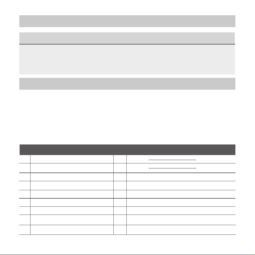
2. Installation accessory
Don’t install at the place where cover with heavy oil, vapor or
sulfureted gas, otherwise, this product would be deformed
that would lead to system malfunction.
Select the installation location
Preparation before installation
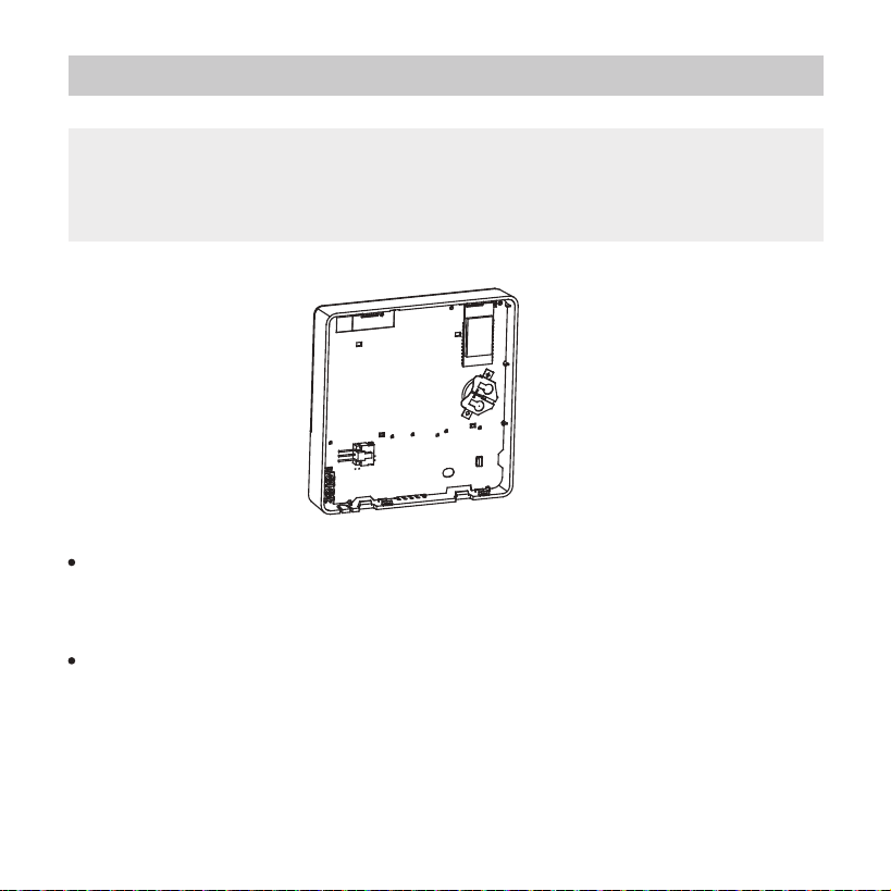
1. Please conrm that all the following parts you have been supply.
1
2
3
4
5
3
2
M3.9*25 (For Mounting on the Wall)
M4X25 (For Mounting on switch box)
6
7
8
3
2
No. Name Qty. Remarks
Wire controller
Installation and owner’s manual
For Mounting on the Wall
Plastic screw bars
Screws
Wall plugs
For fixing on switch box
Optional
Screws
9
Screw
1
1
Battery
The connective wires group
1
1
1
M4X8(For Mounting the connective wire group)
3
2. Installation accessory
Precaution of installingthe wire controller
1. This manual provides the installation method of wired
controller. Please refer to the wiring diagram of this installation
manual to connect the wire controller with indoor unit.
2. The wired controller works in low voltage loop circuit.
Forbid to directly contact the cable of high voltage above,
like 115V,220V,380V, and don’t wire this kind of wire in the
said loop; wiring clearance between congured tubes should
be at the range of 300~500mm or above.
3. The Shielded wire of the wired controller must be grounded
rmly.
4. Upon nish the wire controller connection, do not employed
tramegger to detect the insulation.
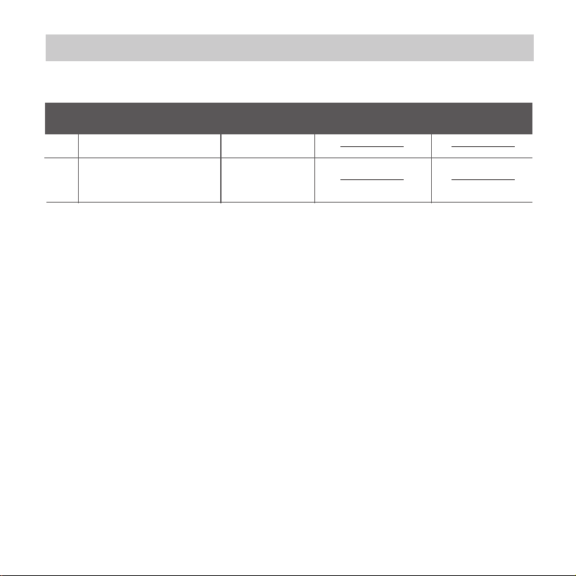
2. Prepare the following assemblies on the site.
1
2
1
Switch box
Wiring Tube(Insulating
Sleeve and Tightening
Screw)
Qty.(embeded
into wall)
No.
Name
Remarks
Specification
(only for reference)
1
4
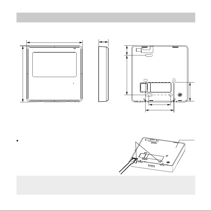
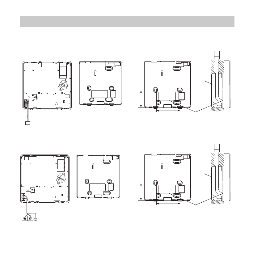
3. Installation method
Fig 3-2
Fig 3-1
1.Wired remote controller structural dimensions
2.Remove the upper part of wired controller
Insert a slot screwdriver into the
slots in the lower part of the wired
controller (2 places), and remove
the upper part of the wire controller.
(Fig.3-2)
19mm84mm
46mm
60mm
44mm
120mm
120mm
Back cover
NOTE: Do not pry up and down, you can only rotate the
screwdriver.
20.6mm
Buckling
position
5
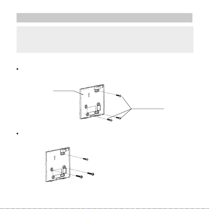
3. Installation method
Fig 3-3
Fig 3-4
For exposed mounting, fasten the back plate on the wall with the
3 screws (ST3.9*25) and plugs. (Fig.3-3)
Use two M4X25 screws to install the back cover on the 86 switch box,
and use one ST3.9*25 screw to x to the wall.
3. Fasten the back plate of the wired controller
Back plate
Screws (ST3.9*25)
Screw hole xed on the wall,useone ST3.9*25mm
Screw hole installed on 86 switch box, use two M4X25mm
NOTE: The PCB is mounted in the upper part of the wired
controller. Be careful not to damage the board with the
slot screwdriver.
6
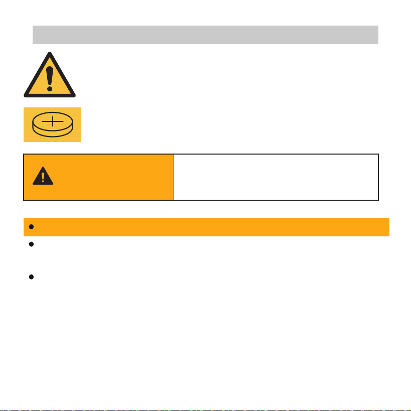
3. Installation method
BATTERY WARNING: KEEP OUT OF REACH OF CHILDREN;
If the battery compartment (if applicable) does not close
securely, stop using the product and keep it away from children;
If you think batteries might have been swallowed or placed
inside any part of the body, seek immediate medical attention.
WARNING: Contains coin battery.
BATTERY WARNING
INGESTION HAZARD: This product
contains a button cell or coin battery.
WARNING
7
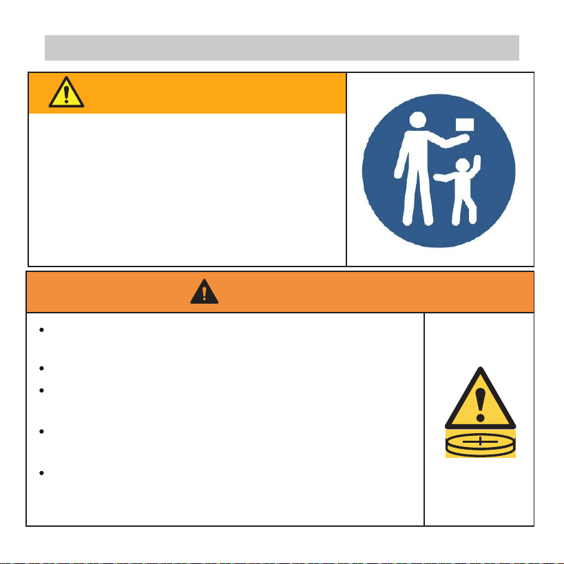
WARNING
INGESTION HAZARD: This product contains a
button cell or coin battery.
DEATH or serious injury can occur if ingested.
A swallowed button cell or coin battery can cause
Internal Chemical Burns in as little as 2 hours.
KEEP new and used batteries OUT OF REACH of
CHILDREN.
Seek immediate medical attention if a battery is
suspected to be swallowed or inserted inside any
part of the body.
KEEP OUT OF REACH OF CHILDREN.
Swallowing can lead to chemical burns,
perforation of soft tissue, and death.
Severe burns can occur within 2 hours
of ingestion. Seek medical attention
immediately.
BATTERY WARNING
3. Installation method
8
WARNING
Remove and immediately recycle or dispose of used batteries
according to local regulations and keep away from children.
Do NOT dispose of batteries in household trash or incinerate.
3. Installation method
Even used batteries may cause severe injury or death.
Call a local poison control center for treatment information.
Non-rechargeable batteries are not to be recharged.
Do not force discharge, recharge, disassemble, heat above
(-20-70℃) or incinerate. Doing so may result in injury due to
venting, leakage or explosion resulting in chemical burs.
Ensure the batteries are installed correctly according to
polarity (+ and -).
Do not mix old and new batteries, dierent brands or types of
batteries, such as alkaline, carbon-zinc, or rechargeable batteries.
Remove and immediately recycle or dispose of batteries from
equipment not used for an extended period of time according
to local regulations.

9
Always completely secure the battery compartment. If the
battery compartment does not close securely, stop using the
product, remove the batteries, and keep them away from
children.
3. Installation method
Battery type: CR2032
Battery power supply: 3.0V
10
3. Installation method
Put the battery into the installationsite and make sure the positive side
of the battery is in accordance with the positive side of installationsite.
(See Fig.3-5)
Please set the time corrected on the rst time operation. Batteries in
the wire controller can time under power failure which ensure the
time keep right. When the power restores, if the time displayed is not
correct, it means the battery is dead and replace the battery.
Fig 3-5
4. Battery installation
NOTE: Put on a at surface. Be careful not to distort the
back plate of the wire controller by overtightening the
mounting screws.
11
3. Installation method
Fig 3-6
5. Wire with the indoor unit
44mm
60mm
Wiring
hole
switch box
A
B
44mm
60mm
Wiring
hole
switch box
Model A
Model B
A
B
HA HB
1
12
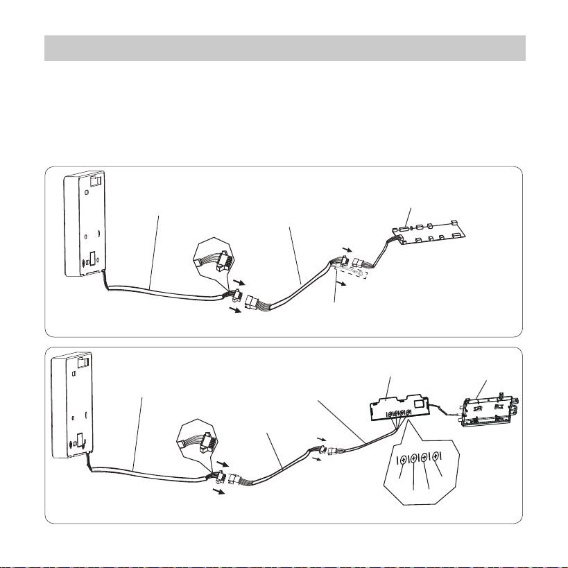
3. Installation method
Model A
Fig 3-7
Fig 3-8
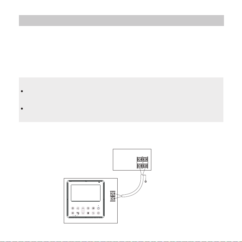
Connect the wire from the display panel of the indoor unit to
a connecting cable. Then connect the other side of the
connecting cable to the remote control.
4-core wire
The connective wires group
shielded wire(some units)
Mainboard
4-core wire
Adaptor board
Display board
The connection cable A
X
Y
E
5V/12V
White
Yellow
Brown
Red
The connection cable D
Applicable to split-type air conditioner
Applicable to Light Commercial air conditioner
13
1 indoor unit
Notch the part for the wiring to pass through with nippers, etc.
Connect the terminals on the wired controller (HA ,HB), and the terminals
of the indoor unit (HA ,HB). (HA and HB do not have polarity.)
For some units, the wired controller connects to the unit HA and HB ports
through the HA and HB ports. There is no polarity between HA and HB.
SeeFig. 3-9
HA HB
Indoor Unit
Wired Controller
Fig.3-9
3. Installation method
DO NOT allow water to enter the wired control.
Use the trap and putty to seal the wires.
Connecting wires must be xed reliably and cannot be
pulled.
NOTE:
Model B
14
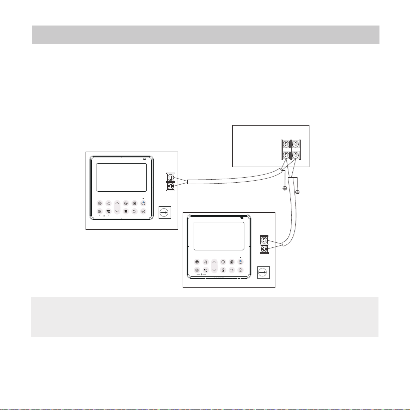
The main/secondary wired controller can be used to enable
two wired controllers to control one unit, and the wired
controllers connect to the unit HA and HB ports through the
HA and HB port on the controller. There is no polarity
between HA and HB. SeeFig. 3-10
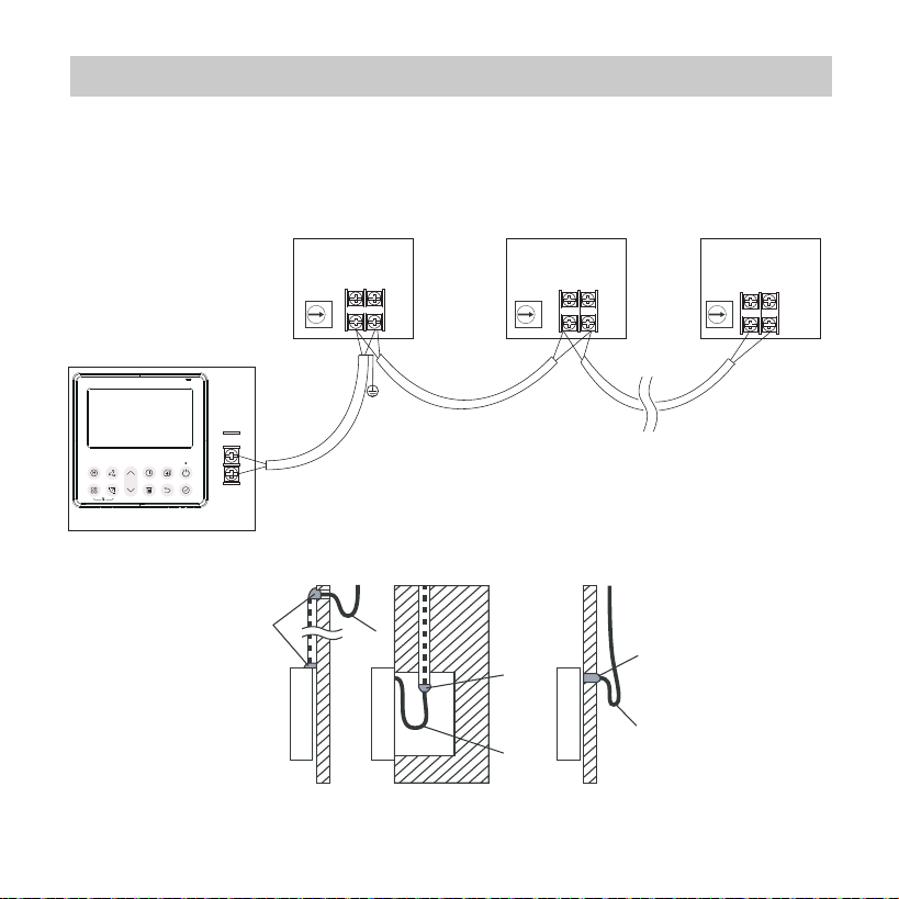
For some units, one wired controller can support multiple units
(a maximum of 16 units). In this case, the wired controller and
NOTE:
Wire controller with Wireless function does not have
this function
.
3. Installation method
HA HB
HAHB
HAHB
Indoor Unit
Wired Controller 1
Wired Controller 2
Fig.3-10
0
1
15
unit need to be connected to the HA and HB ports at the same
time. In group control, there will be no error displayed on the
wired controller. SeeFig. 3-11
3. Installation method
Fig 3-12
Putty
Putty
Putty
Trap
Trap
Trap
HA HB
HA HB
HA HB
Indoor Unit 2 Indoor Unit n
(n<=16)
Indoor Unit 1
Wired Controller 1
HAHB
Fig.3-11
0 1 2
.....
16
Fig 3-13
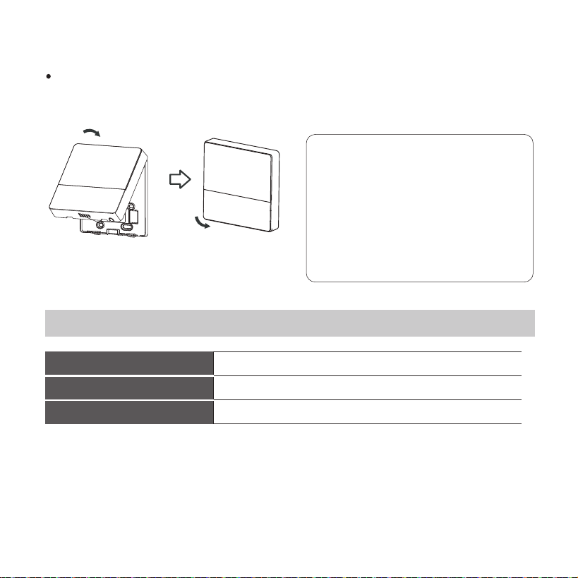
6. Reattach the upper part of the wired controller
After adjusting the upper case and then buckle the upper case;
avoid clamping the wiring during installation. (Fig 3-13)
All the pictures in this
manual are for
explanation purpose only.
Your wire controller may
be slightly dierent .The
actual shape shall prevail.
4. Specification
Wiring specications
12V
0~43℃(32~110℉)
RH40%~RH90%
Input voltage
Ambient temperature
Ambient humidity
NOTE: Suggested to use the connective wire of 6 meters length.
17
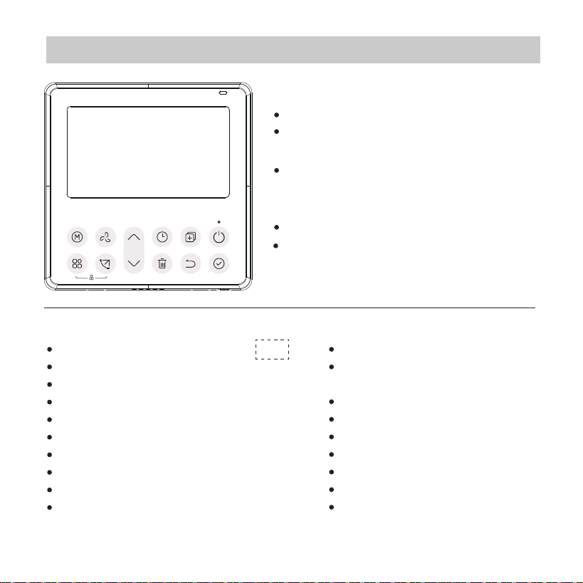
5. Feature and function of the wired controller
Feature:
Function:
LCD display.
Malfunction code display: it can display
the error code, helpful for service.
4-way wire layout design, no raised
part at backside, more convenient
to place the wires and install the device.
Room temperature display.
Weekly Timer.
Mode: Choose Auto-Cool-Dry- Heat -Fan
Fan speed: Auto/Low/Med/High speed
Swing(on some models)
Timer ON/OFF
Temp setting
Weekly timer
Follow me
Turbo
24-hour System
12-hour System
Auto-restart
Individual louver control
(on some models)
Automatic airow test
Rotation&Back-up
Dual Control
Group Control
Child Lock
LCD display
Clock
18
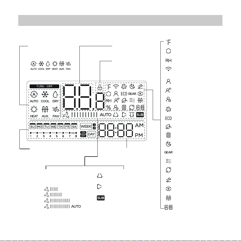
6. Name on the LCD of the wired controller
MODE display
Displays the current
mode,including:
Weekly Timer/ ON/Off Timer
display
Clock display
FAN SPEED display
Displays selected fan
speed:
LOW
MED
HIGH
AUTO
VERTICAL SWING
display
Secondary unit
display
°C / °F display
Room temperature display
Relative humidity display
HORIZONTAL SWING
display
Temperature display
Lock display
Follow me feature display
Turbo feature display
ECO feature display
GEAR feature display
SLEEP feature display
Filter reminder display
Purify feature display
Wireless control feature
display
Breeze away display
Breezeless display
Rotation display
Active clean display
Intelligent eye display
Electric heating display
Main unit and secondary
unit display
Delay off display
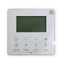
19
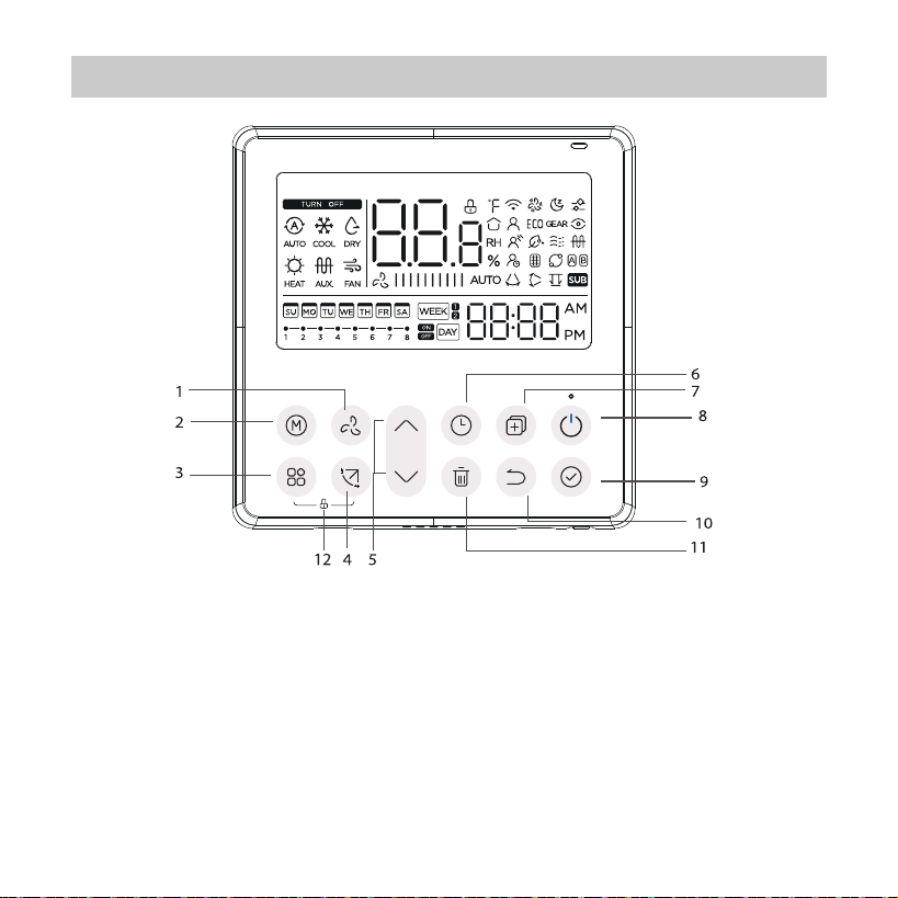
1 FAN SPEED button
2 MODE button
3 FUNC. button
4 SWING botton
5 ADJUST button
6 TIMER button
7 COPY button
8 POWER button
9 CONFIRM button
10 BACK botton
11 DAY OFF/DELAY button
12 CHILD LOCK button
7. Name of button on the wired controller
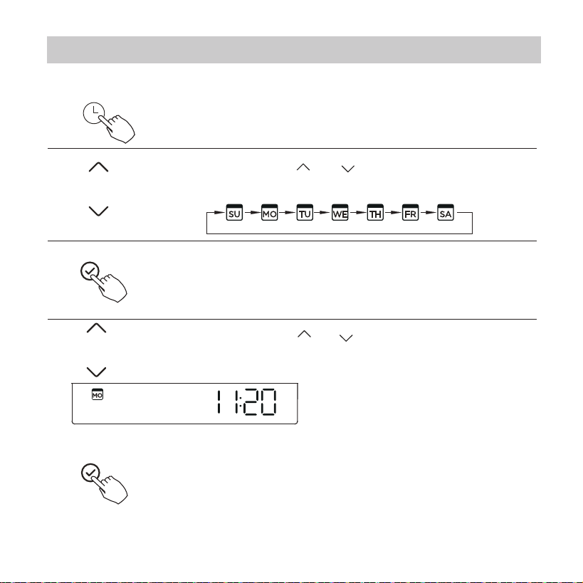
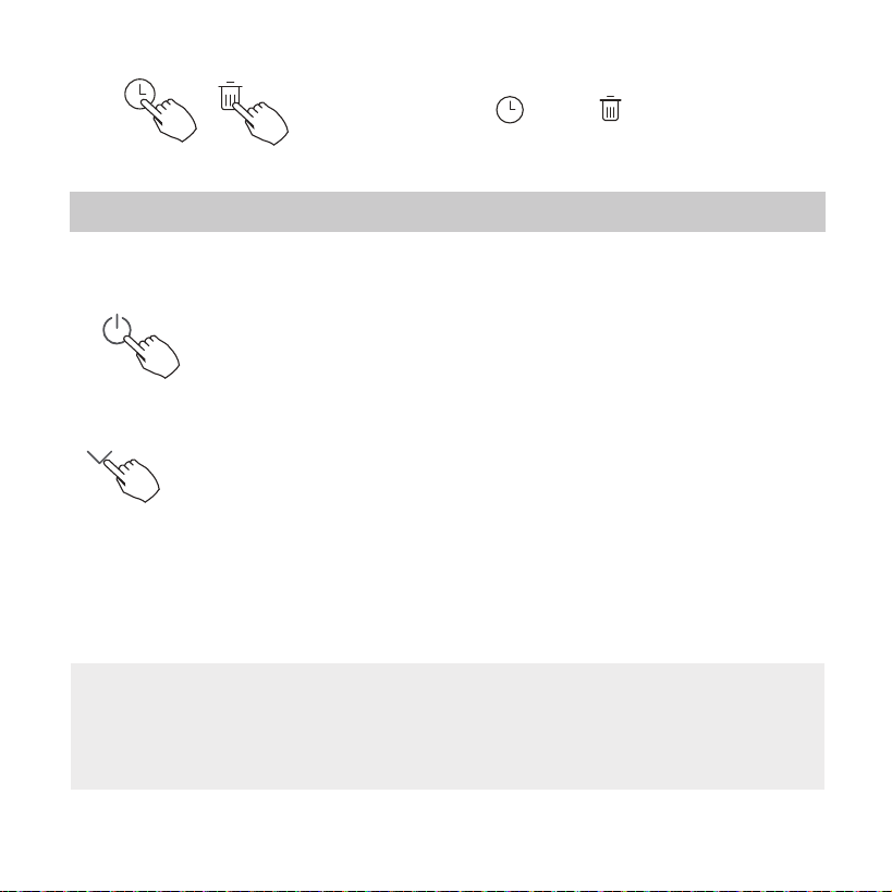
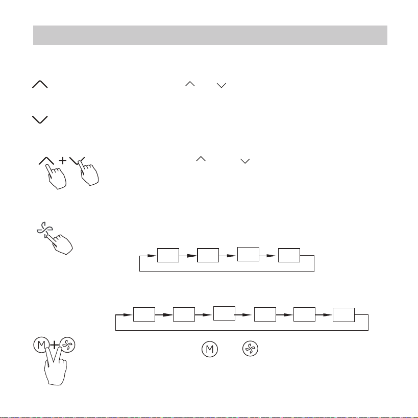
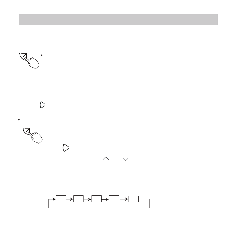
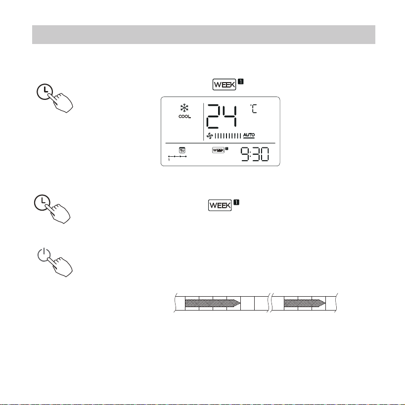
Press the button “ ” or “ ” to set the current time.
Press repeatedly to adjust the current time in 1-minute
increments. Press and hold
to adjust the current time
continuous.
20
5
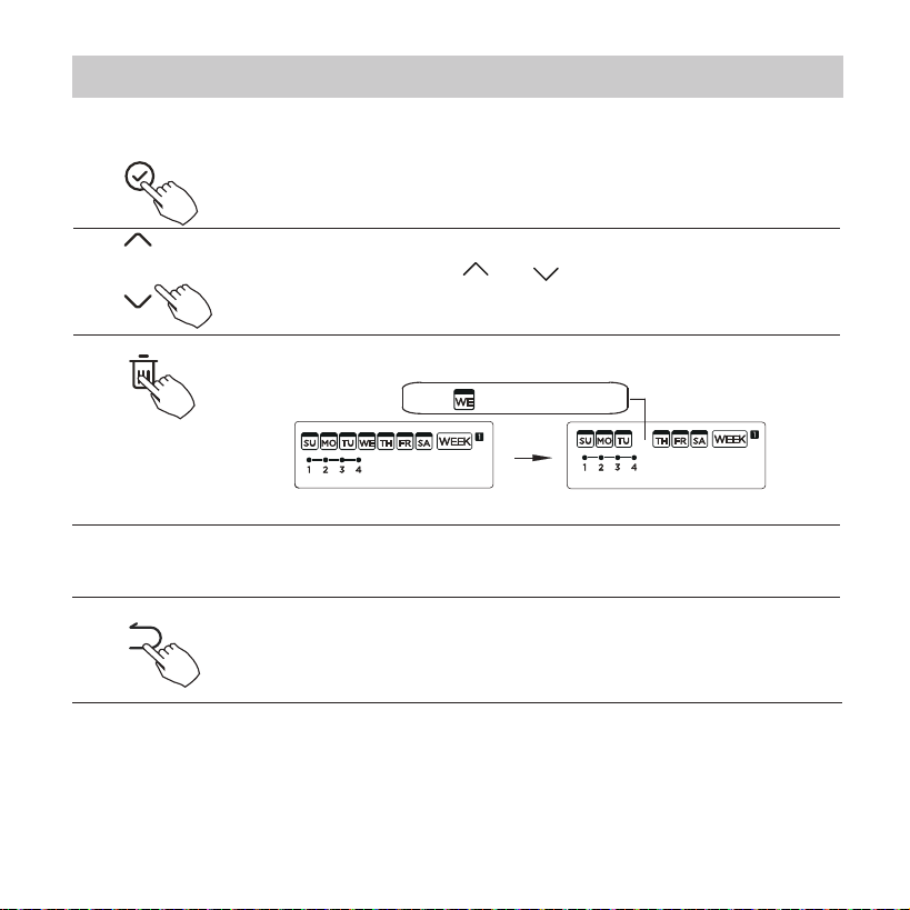
Press the Timer button for 2 seconds or more.
The timer display will ash.
1
2
3
4
The date setting is nished and the time setting is prepared
after pressing Timer button or CONFIRM button or there is
no pressing button in 10 seconds.
The setting is done after pressing CONFIRM button or
there is no pressing button in 10 seconds.
Set the current day and time
ex.Monday 11:20
Press the button “ ” or “ ” to set the date.
The selected date will ash.
8. Preparatory operation
Time scale selection
Press the buttons “ ” and “ ” for 2 seconds
will alternate the clock time display between the
12h & 24h scale.
21
9. Operation
To start/stop operation
Press the Power button.
6
8 degree heating function (on some models)
NOTE:
For some models, the 8° heating function can only be set by remote control,
you can not choose this function by wired controller.
When the heating mode is 10°C(50°F )/16°C(60°F)/17°C (62°F ) /
20°C( 68°F ) , press the down button twice within 1 second to turn on the
8 ° heating function, and press the Power, Mode, adjust , Fan speed, Timer,
and Swing button to cancel the 8° heating function.
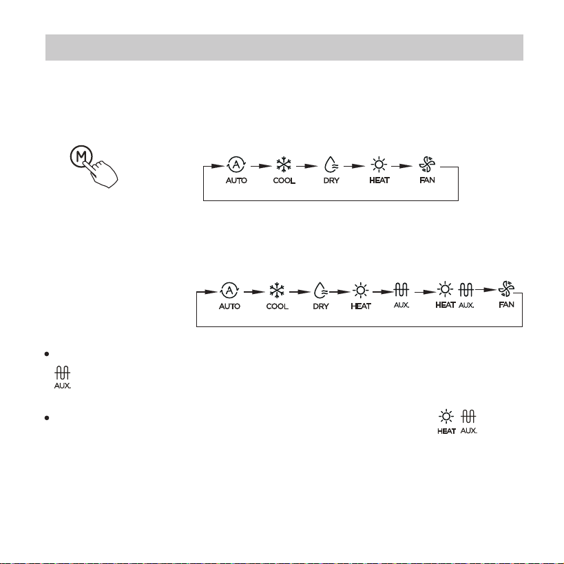
When the mode is selected as emergency heating (or electric heating) mode,
is displayed, the fan speed is Auto. The Sleep, 8-degree heating, Turbo,
and Rotation functions are not available in emergency heating mode.
When the mode is selected as heating & electric heating mode, is
displayed, and the Turbo and Rotation functions are disable.
22
9. Operation
To set the operation mode
Press this button to select the operation mode:
If the indoor unit has Electric heating(Emergent
heating) feature, press this button to select the
operation mode:
Operation mode setting(Heat mode is invalid for cool only type unit)
Press the buttons “ ” and “ ” for 3 seconds will
alternate the temperature display between the °C & °F
scale.
23
9. Operation
Room temperature setting
Fan speed setting
Press the Fan speed button to set the fan speed. (This
button is unavailable under Auto or Dry mode)
Auto LOW MED HIGH
Press the buttons and together for
3 seconds to turn on or turn o the keypad tone.
°C & °F scale selection (on some models)
When stepless speed regulation is supported, press the
fan speed key to cycle through:
Auto
20% 40% 60% 80%
100%
Press the button“ ”or “ ” to set the room temperature.
Indoor Setting Temperature Range :
10/16/17~30°C (50/60/62~86°F ) or 20~28°C(68~82°F ).
(Model dependent)
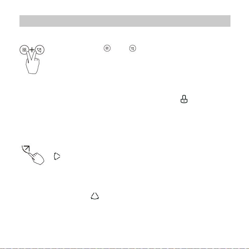
When the child lock function is activated, the” ”mark appears.
24
9. Operation
Child lock function
2 Left-Right swing
Press the Swing button for 2 seconds to start Left-Right swing
function. The “ ” mark appears. Press it for 2 seconds again
to stop.
1 Up-Down swing
Press the SWING button to start up-down swing function. The
“ ” mark appears. Press it again to stop.
Swing function(For the units with horizontal & vertical
swing features only)
Press the buttons “ ” and “ ” for 3 seconds to activate the
child lock function and lock all buttons on the wire controller.
You can't press the button to operate and receive the remote
control signal after the child lock is activate.
Press these two buttons again for 3 seconds to deactivate the
child lock function.
25
9. Operation
For the units with four Up-Down louvers, it can be operated individually.
Swing function(For the units without vertical swing
function )
1.Each time you press this button, the louver swings an angle of 6 degrees.
Press this button until the desired direction reaches.
2.If press and hold the button for 2 seconds, the auto swing is activated.
The “ ” mark appears. Press it again to stop. (some units)
Use Swing button to adjust the Up-down airow direction and
start the auto swing function.
2.Pressing the button “ ” or “ ” can select the movement of
four louvers.Each time you push the button, the louver will be
selected in a sequence as:
( means the four louvers move at the same time.)
1.Press the Swing button to activate the Up-Down adjusting
louver function.
The mark will ash.(Not applicable to all the models)
-0
-0
-1
-2
-3
-4
[ ]: Model dependent. If the indoor unit has no this function, it
will not display.
26
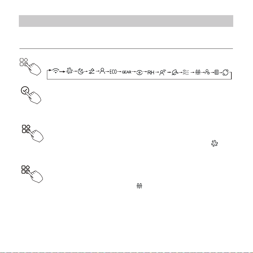
Press the FUNC. button to scroll through operation functions
as followings:
3. And then use Swing button to adjust the Up-Down airow direction of
the selected louver.
Turbo function (on some models)
Under COOL/HEAT mode, press the FUNC. button to activate
the turbo function. Press the button again to deactivate the
turbo function. When the turbo function is activated,the “ ”
mark appears.
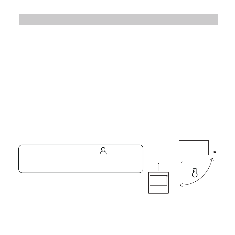
Press the FUNC. button to select whether the room temperature is detected
at the indoor unit or the wire controller.
Follow me function indicator
The select function icon will ash, then press the Conrm
button to conrm the setting.
*
PTC function (on some models)
In heating operation, for the units with electric heating feature,
press this button to activate electric heating mode. When the
PTC function is activated,the “ ”mark appears.
NOTE: The electric auxiliary heating function of the AHU model is switched
by the MODE button , and the FUNC. button is a turbo function.
9. Operation
* *
*
*
*
*
*
*
*
*
*
*
*

27
Intelligent eye display
1.This function is valid in any mode of power-on state.
2.When the indoor unit sending wire controller has the smart eye
function, press the function key to select the smart eye icon, press
the OK key to turn on the smart eye, and light up the smart eye icon
at the same time; when the smart eye is turned o, the smart eye
icon goes out.
3.Shutdown, switch mode, turn on self-cleaning, turn on 8-degree
heating function will automatically cancel the smart eye function.
Filter reset function
After the indoor unit sends the wire controller lter usage time,
the lter cleaning prompt icon lights up, press the function key
to select the lter cleaning prompt icon, and press the OK key to
reset the lter screen time. The lter cleaning reminder icon goes
out.
9. Operation

28
Humidity setting function
1.When the indoor unit sending wire controller has dual control
function of temperature and humidity, in dehumidication mode,
press the function key to select the RH icon, press the conrm key
to enter the humidity control mode, the RH icon ashes, press the
up and down keys to adjust the humidity, the setting range is
OFF->35%~85%, adjusted with 5% humidity. Exit humidity
adjustment state after 5 seconds of inactivity.
2.After entering the humidity control mode, press the up and down
keys to adjust the set temperature and display the set temperature
for 5 seconds, and then restore the set humidity display.
3.After switching the mode, exit the humidity control mode.
9. Operation
29
Press the button again to cancel the
follow me function.
Indoor Unit
When the follow me function indicator
appears,the room temperature is detected by
the wire controller.
GEAR function
1.When the indoor unit sending wire controller has the GEAR
function, in the boot cooling mode, press the function key to
select the GEAR icon, press the conrm key to enter the GEAR
control mode, and rst display the current GEAR status.
50%->75%->OFF can be switched by the up and down keys
within 5 seconds. After 5 seconds, the set temperature will be
displayed, press the up and down keys to adjust the set
temperature.
Turn o, switch to mode or turn on sleep, ECO, strong, self-cleaning
functions to cancel the GEAR function.
9. Operation

30
When there are two units, press the button to select the rotating function,
and press “Conrm”to turn on or o the rotating function.
Rotation & Back-up indication
5. After this function is turned on, as long as the air conditioner is running at
the setting hour, it will automatically turn on another air conditioner and
turn o the current air conditioner. Press the
POWER
button
to switch to
another one immediately.A or B icons icker to indicate the corresponding
air conditioning failure. Automatically switch to another machine when
running time is reached or machine failure occurs.
1. Press “Conrm” to set the rotating time,then press the button “ ”or “ ”
to set time. Setting time Range :1~99h,the default time is 10 hours.
2. Step 2 set high temperature co-open temperature -- or 26~32 degrees --
that is, this function is invalid. When the ambient temperature is 26~32
degrees, when the ambient temperature is greater than or equal to the set
temperature, the two machines will run 24 degrees at the same time in the
COOL mode.
3. Step 3 set the low-temperature co-open temperature -- or 5-15 degrees --
that is, this function is invalid. When the ambient temperature is 5-15 degrees,
when the ambient temperature is lower than the set temperature, the two
units will run at the same time for 24 degrees to make the heating mode.
4. Step 4: set which machine will run rst. Select A or B.
9. Operation
31
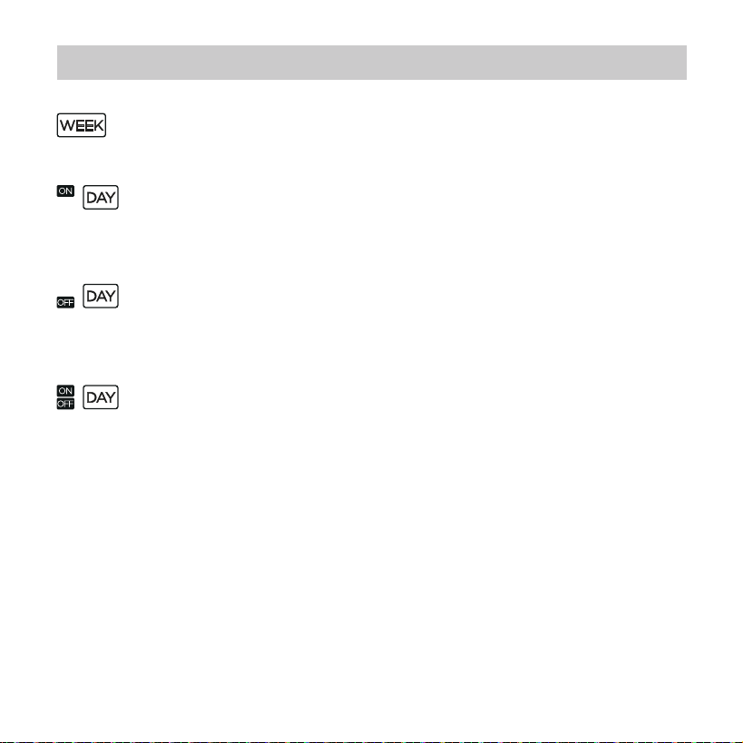
WEEKLY timer
Use this timer function to set operating times for each day of the
week.
On timer
Use this timer function to start air conditioner operation.
The timer operatesand air conditioner operation starts after the
time has passed.
O timer
Use this timer function to stop air conditioner operation.
The timer operates and air conditioner operation stops after the
time has passed.
On and O timer
Use this timer function to start and stop air conditioner operation.
The timer operates and air conditioner operation starts and stops
after the time has passed.
10. Timer functions
32
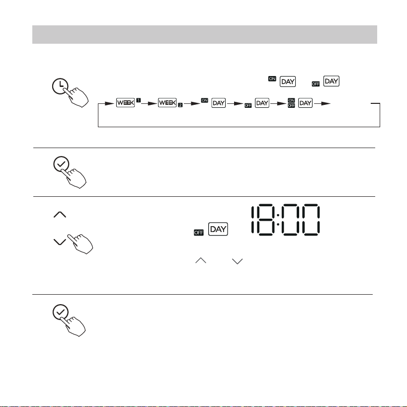
To set the On or Off TIMER
No display
1
2
Press the Conrm button and the Timer display is ashing.
Press the Conrm button again to nish the settings.
3
ex.O timer set at 18:00
4
Press the button “ ” or “ ” to set the time.
After the time is set, the timer will start or stop automatically.
Press the Timer button to select the or .
10. Timer functions
33
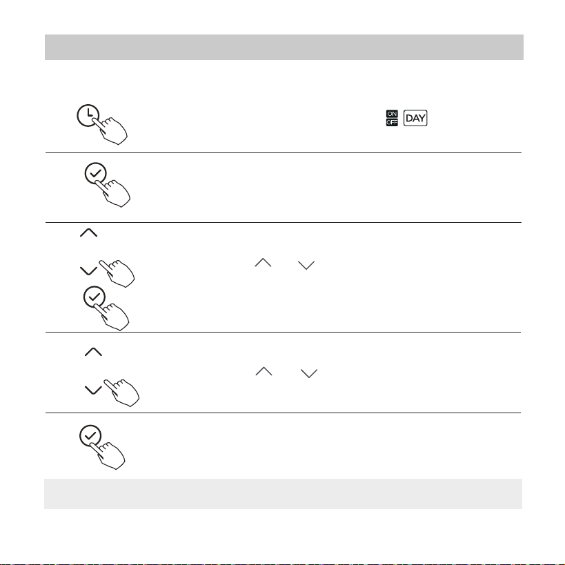
Press the Conrm button to nish the settings.
To set the On and Off TIMER
Press the Timer button to select the .
1
2
Press the Conrm button and the Clock display is ashing.
3
Press the button “ ” or “ ” to set the time of On timer,
and then press the Conrm button to conrm the setting.
4
5
Press the button “ ” or “ ” to set the time of O timer.
NOTE:
The secondary wired controller cannot set the timer.
10. Timer functions
Press the button “ ” or “ ” to set the time of On timer
and then press the Conrm button to conrm the setting.
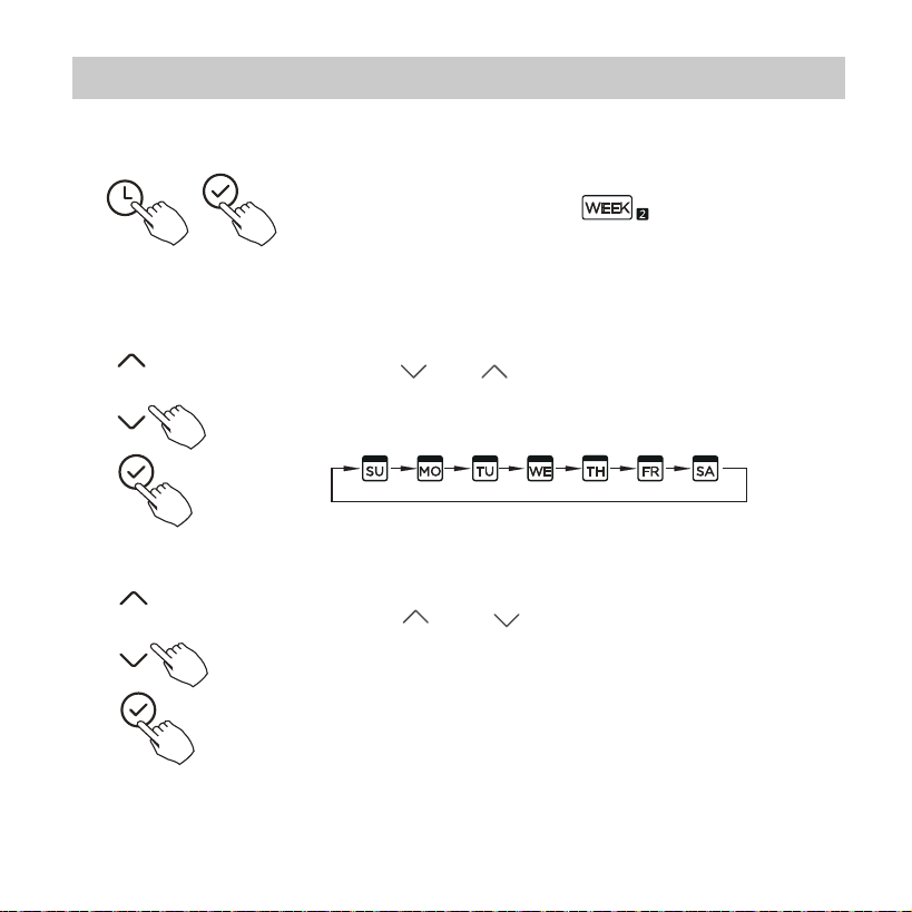
Press the button “ ” or “ ” to select the day of the
week and then press the Conrm button to conrm
the setting.
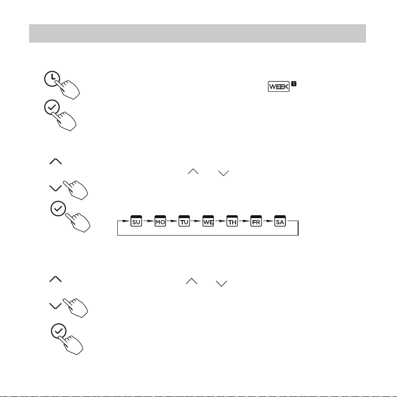
34
Press the Timer button to select the and then
press the Conrm button to conrm.
Weekly timer setting
1
2
Day of the week setting
ON timer setting of timer setting 1
3
11. Weekly Timer 1
35
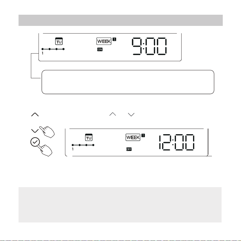
ex.Tuesday time scale 1
Dierent timer settings can be setted by repeating step 3 to 4.
Other days in one week can be setted by repeating step 2 to 5.
4
Off timer setting of timer setting 1
5
6
ex.Tuesday time scale 1
Press the button “ ” or “ ” to set the time of O timer
and then press the Conrm button to conrm the setting.
NOTE: The weekly timer setting can be returned to the previous step by
pressing Back button.The time of timer setting can be delete by pressing
Day o botton The current setting will be restored and withdrawn the weekly
timer setting automatically when there is no operation for 30 seconds.
Up to 4 timer settings can be saved for each day of the week.
It is conventent if the WEEKLY TIMER is set according to the
user’s life style.
11. Weekly Timer 1
36
To activate WEEKLY TIMER operation
WEEKLY timer operation
To deactivate WEEKLY TIMER operation
To turn off the air conditioner during the weekly timer
1. If press the Power button once and quickly , the air conditioner
will turn o temporarily. And the air conditioner will turn on
automatically until the time of On timer.
ON OFF ON OFF
8:00 12:00 14:00 17:0010:00
ex. If press the POWER button once and quickly at 10:00, the air
conditioner will turn on at 14:00.
2. When press the Power button for 2 seconds , the air conditioner
will turn o completely
,at the same time cancel the timing function.
Press the Timer button while is displayed on the LCD.
Press the Timer button while is disappear from the LCD.
ex.
11. Weekly Timer 1
37
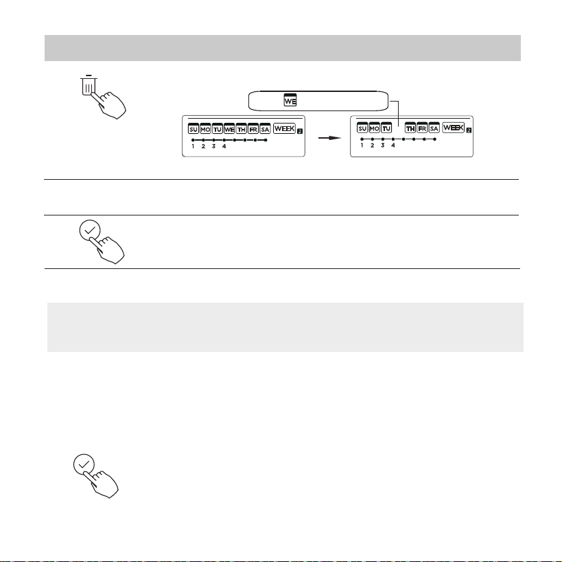
To set the DAY OFF (for a holiday)
During the weekly timer, press the Conrm button.
1
2
Press the Back button to back to the weekly timer.
Press the Day o button to set the DAY OFF.
3
5
To cancel:Follow the same procedures as those for setup.
4
ex.The DAY OFF is set for Wednesday
The DAY OFF can be setted for other days by repeating
the steps 2 and 3.
The mark is hidden
NOTE:
The DAY OFF setting is cancelled automatically after the set day has passed.
Press the button “ ” or “ ” to select the day in this
week .
11. Weekly Timer 1
38
Press the button “ ” or “ ” to select the day to
copy from.
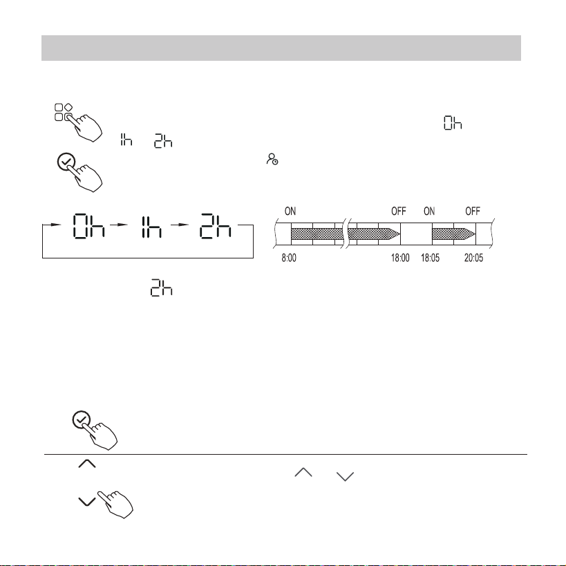
During the weekly timer, press the FUNC. button , select the
delay function and press the Conrm button,display" "
" " " " and wait 3 seconds to conrm. When the delay
function is activated,the “ ”mark appears.
The delay function can only be enabled in Weekly Timer 1 and
Weekly Timer 2.
DELAY function
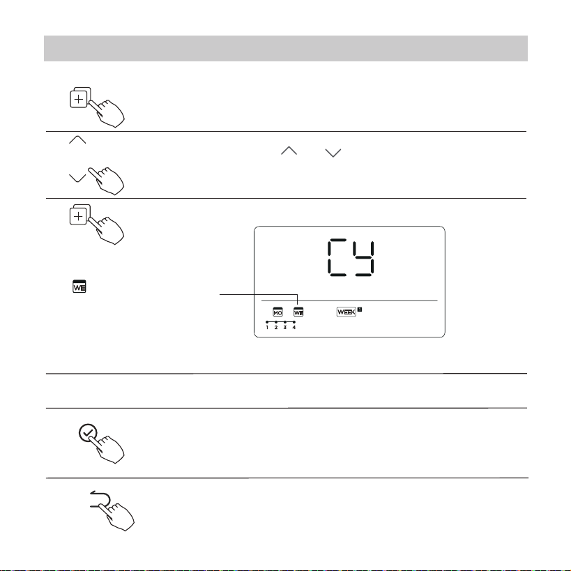
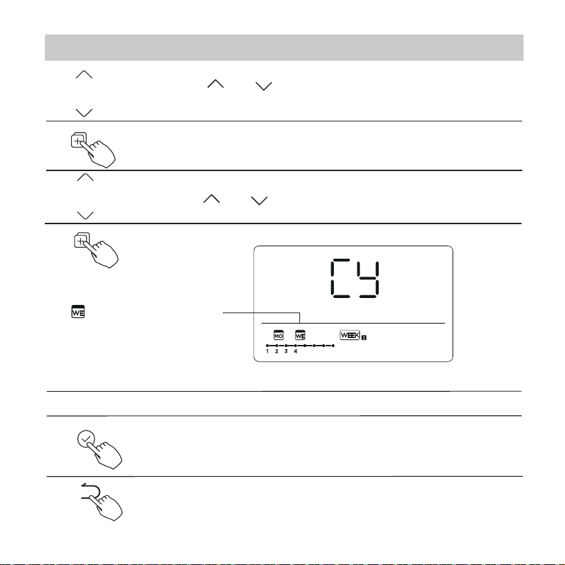
Copy out the setting in one day into the other day.
During the weekly timer, press the Conrm button.
1
A reservation made once can be copied to another day of the week. The
whole reservation of the selected day of the week will be copied. The
eective use of the copy mode ensures ease of making reservations.
2
ex. If press select “ ” at 18:05, the air conditioner will delay to turn o
at 20:05.
11. Weekly Timer 1
39
Press the Copy button,the letter “CY” will be shown on
the LCD.
3
4
Press the button “ ” or “ ” to select the day to copy
to.
Press the Conrm button to conrm the settings.
Press the Back button to back to the weekly timer.
5
Press the Copy button to conrm.
Other days can be copied by repeating step 4 and 5.
ex. Copy the setting of Monday to Wednesday
The mark ashes quickly
6
7
8
11. Weekly Timer 1
40
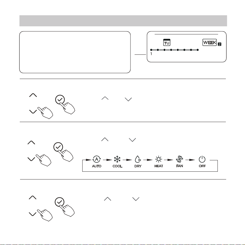
Press Timer to select the and press Conrm.
Press “ ” or “ ” to select the setting time. The
setting time, mode, temperature and fan speed
appear on the LCD. Press CONFIRM to enter the
setting time process.
Press “ ” or “ ” to select the day of the week
and then press CONFIRM.
Weekly timer setting
1
2
Day of the week setting
ON timer setting of timer setting 1
3
11. Weekly Timer 2
41
Press “ ” or “ ” to set the room temperature,
then press CONFIRM.
NOTE: This setting is unavailable in the FAN or OFF
modes.
Press “ ” o r “ ” to set the operation mode
then press CONFIRM.
Press “ ” or “ ” to set the time, then press
CONFIRM.
ex.Tuesday time scale 1
IMPORTANT: Up to 8 scheduled events
can be set on one day.
Various events can be scheduled in
either MODE, TEMPERATURE and FAN
speeds.
4
Time setting
5
Operation mode setting
6
Room temperature setting
12. Weekly Timer 2
42
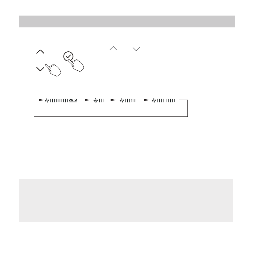
Press “ ” or “ ” to set the fan speed then press
CONFIRM.
NOTE: This setting is unavailable in the AUTO,
DRY or OFF modes.
7
Fan speed setting
Different scheduled events can be set by repeating
steps 3 through 7.
8
Additional days, in a one week period, can be set by
repeating steps 3 through 8.
9
NOTE:
The weekly timer setting can be returned to the
previous step by pressing BACK. The current setting is restored.
The controller will not save the weekly timer settings if there
is no operation within 30 seconds.
12. Weekly Timer 2
43
Press “ ” or “ ” to select the day of the week.
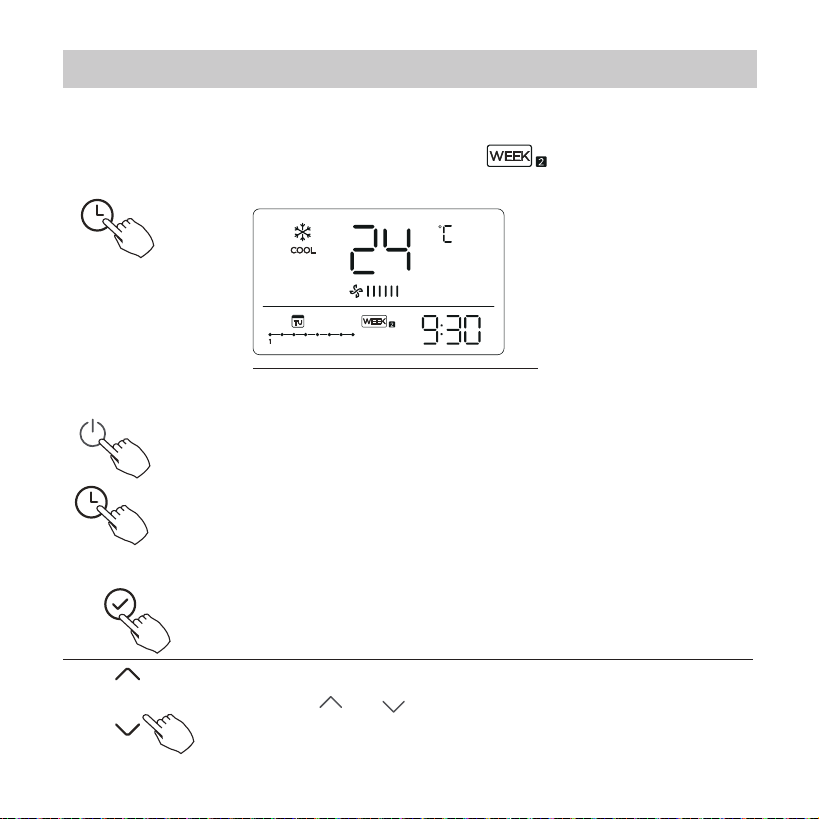
Press Timer to select the , and then the timer
starts automatically.
To start
WEEKLY timer operation
ex.
To cancel
To set the DAY OFF (for a holiday)
After setting the weekly timer, press CONFIRM.
1
2
The timer mode can also be canceled by changing the
timer mode using Timer.
Press the Power buttons for 2 seconds to cancel the
timer mode.
12. Weekly Timer 2
44
NOTE:
The DAY OFF setting is cancelled automatically after
the set day has passed.
The mark is hidden
Press BACK to revert to the weekly timer.
Press DAY OFF to create an o day.
3
5
To cancel, follow the same procedures used for setup.
4
ex.The DAY OFF is set for Wednesday
Set the DAY OFF for other days by repeating the steps 2 and 3.
Copy out the setting in one day into the other day.
In the weekly timer, press CONFIRM.
1
A scheduled event, made once, can be copied to another day of the week.
The scheduled events of the selected day of the week will be copied. The
eective use of the copy mode ensures the ease of reservation making.
12. Weekly Timer 2
45
The mark ashes quickly
Press COPY, the letters CY appear on the LCD.
3
4
Press CONFIRM to conrm the settings.
Press BACK to revert to the weekly timer.
5
Press COPY to conrm.
Other days can be copied by repeating steps 4 and 5.
ex. Copy the setting of Monday to Wednesday
6
7
8
Press “ ” or “ ” to select the day to copy to.
2
Press “ ” or “ ” to select the day to copy from.
12. Weekly Timer 2
46
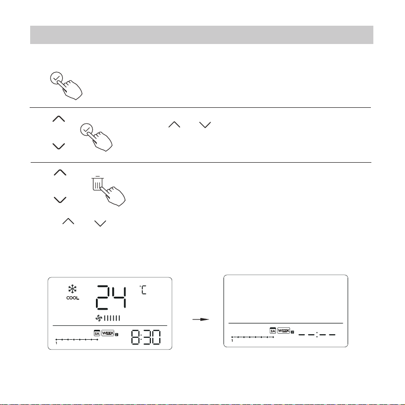
Press “ ” or “ ” to select the day of the week
and then press CONFIRM.
Press “ ” or “ ” to select the setting time want to delete. The setting
time, mode, temperature and fan speed appear on the LCD. The setting
time, mode, temperature and fan speed can be deleted by pressing the
DEL (day o).
Delete the time scale in one day.
During the weekly timer setting, press CONFIRM.
1
2
3
ex. Delet the time scale 1 in saturday
12. Weekly Timer 2
47
14.Technical indication and requirement
If the system does not properly operate except the above
mentioned cases or the above mentioned malfunctions is
evident, investigate the system according to the following
procedures.
The error displayed on the wire controller are dierent from
those on the unit. If error code appears, please check the
<<Owner’s And Installation Manual>>and<<SERVICE Manu-
al>>.
EMC and EMI comply with the CE certication requirements.
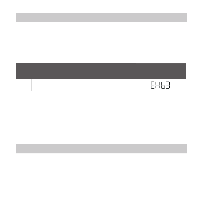
MALFU N C T ION & PROT EC T ION D EFI N E
D I SPLAY
DIGITAL TU BE
NO.
1
Error of communication between wire controler
and indoor unit
13. Fault alarm handing
48
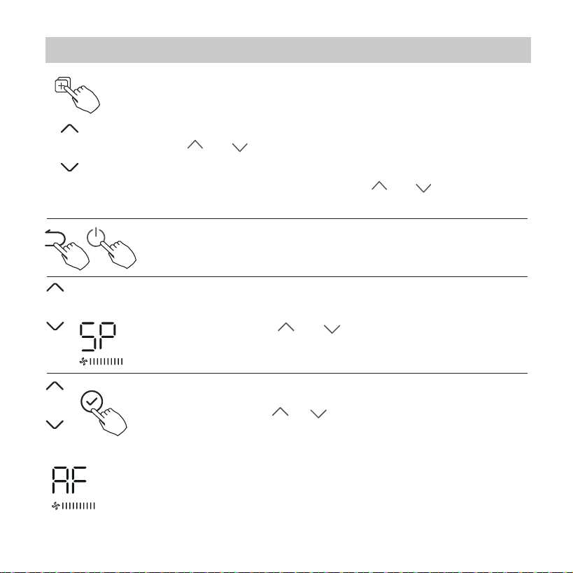
When the air conditioning unit is o, into the query function
of temperature, press“ ”or “ ”to select AF, press “Conrm”
into test mode, press “Back” or press “ON/OFF” or press
“Conrm”drop out of test mode.In AF mode, 3~6 minutes test
completion automatically exits, if the test process, press “Back”
or press “ON/OFF”or press “Conrm” , the test exits will be
interrupted.
When the air conditioning unit is o, into the query function
of temperature, press“ ” or “ ”to select SP, press “Conrm”
to adjust the static pressure value.
When the air conditioning unit is switch machine, Long press
“COPY” for 3 seconds , rst display P:00, if connected to an
indoor unit, display P:00, if connected to multiple indoor units,
press “ ”or “ ”to display P:01, P:02, and then press
“Conrm” to enter the query indoor unit Tn(T1~T4)
temperature and fan fault (CF), press“ ”or “ ”to select.
Not operating keys 15 seconds or press “Back” or press
“ON/OFF”drop out of query temperature.
15.Queries and settings
49
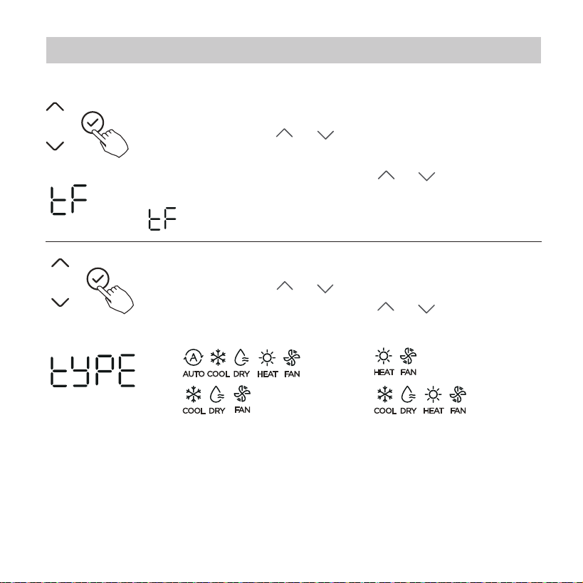
When the air conditioning unit is o, into the query function
of temperature, press“ ”or “ ”to select tyPE.
Press “Conrm” into setting state, press“ ”or “ ”to select
the type, then press “Conrm” to complete it.
When the air conditioning unit is o, into the query function
of temperature, press“ ”or “ ”to select tF.
The compensation temperature Range : -5~5
°C
.
Press “Conrm” into setting state, press“ ”or “ ”to select
the temperature, then press “Conrm” to complete it.
: compensation temperature
Follow me function temperature compensation
CH:
CC: NA:
HH:
15.Queries and settings
50
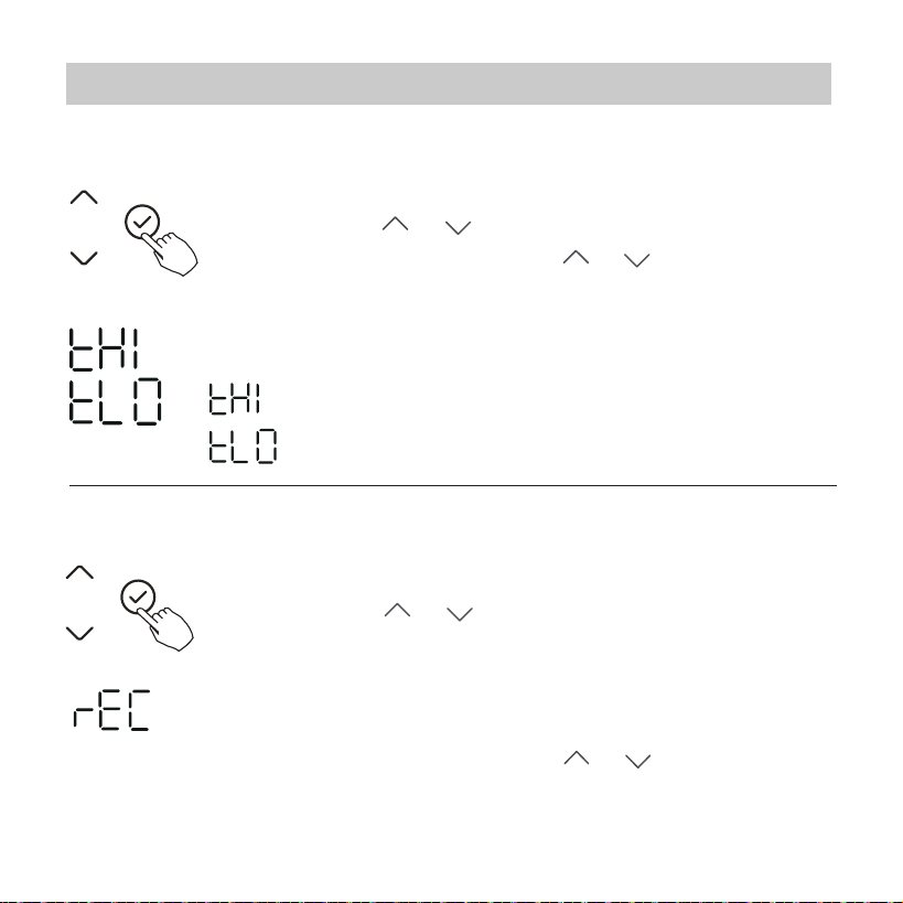
When the air conditioning unit is o, into the query function of
temperature, press“ ”or “ ”to select rEC. ON or OF will be
displayed in the temperature area to indicate whether it is valid
or invalid.
When the selection is invalid, the wire controller does not process
any remote control signals.
Press “Conrm” into setting state, press“ ”or “ ”to select ,
then press “Conrm” to complete it.
When the air conditioning unit is o, into the query function of
temperature, press“ ”or “ ”to select tHI or tLo.
Press “Conrm” into setting state, press“ ”or “ ”to select the
temperature, then press “Conrm” to complete it.
The highest setting temperature range : 25~30
°C
The lowest setting temperature range: 17 ~24
°C
.
: Highest value setting function.
: Minimum value setting function.
Remote control function selection of wire controller
Set the highest and lowest temperature values
15.Queries and settings
-- : The code setting of the wire controller shall prevail.
51
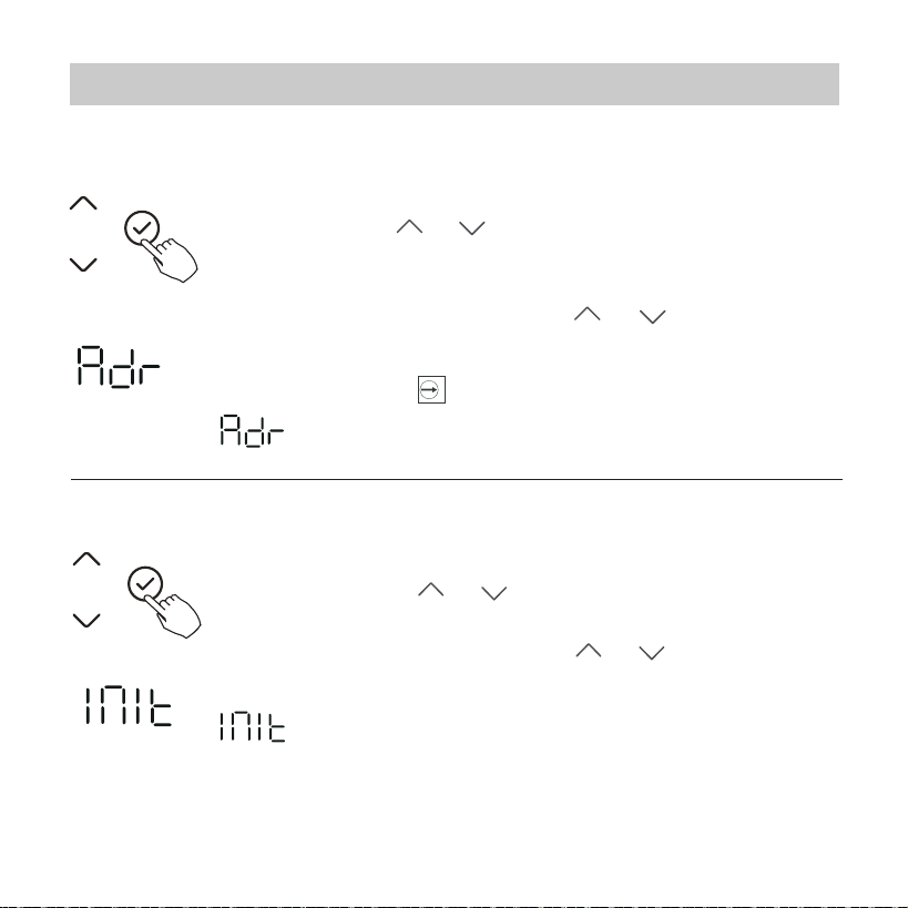
When the air conditioning unit is o, into the query function of
temperature, press“ ”or “ ”to select Adr, the temperature
zone will display -- or A, B. Where -- refers to the code setting
of the wirecontroller.
Press “Conrm” into setting state, press“ ”or “ ”to select ,
then press “Conrm” to complete it.
Two - line controller address selection
Restore factory Settings
: The wire controller address setting.
: Restore factory Settings .
When the air conditioning unit is o, into the query function
of temperature, press“ ”or “ ”to select INIt, the temperature
zone displayed --.
Press “Conrm” into setting state, press“ ”or “ ”to select to
"ON" , then press “Conrm” to complete it.
15.Queries and settings

52
After the wire controller resumes the factory parameter setting, the
rotating parameter setting is restored to 10 hours (the highest and
lowest temperature are not set); The compensation of body temperature
is uncompensated; COOL and HEAT/single COOL mode is restored to
COOL and HEAT model;
Restore the temperature range to the factory setting.
Remote receiving function is restored to be eective;
The address of the two-control rst-line controller is restored to the
code switch.
15.Queries and settings

53
16.Wireless control connection
Read the safety precautions carefully before installing the unit.
Stated below are important safety issues that must be obeyed.
Applicable system: IOS, Android. (Suggest: IOS 9.0 and above,
Android 6.0 and above.)
NOTE:
Wireless safety strategy
Smart kit only support WPA-PSK/WPA2-PSK encryption
and none encryption. WPA-PSK/WPA2-PSK encryption
is recommended.
SAFETY PRECAUTION
Due to special situation may be occured, we explicitly claim
below: Not all of the Andriod and IOS systems are compatible
with APP. We will not be responsible for any issues as a result
of the incompatibility.

54
CAUTION
• Please Check The Service Website For More Information.
• Smart Phone camera needs to be 5 million pixels or above
to make sure scan QR code well.
•
Due to dierent network situation, sometimes, request
time-out could happen, thus, it is necessary to do network
conguration again.
Due to dierent network situation, control process may
return time-out sometimes. If this situation occurs, the
display between board and App may not be the same,
please do not feel confused.
•
NOTE:
Company will not be liable for any issues and problems
caused by Internet, Wireless Router and Smart Devices.
Please contact the original provider to get further help.
16.Wireless control connection
55
DOWNLOAD AND INSTALL APP
· Please ensure your mobile device is connected to Wireless Network router.
Also, the Wireless Network router has already connected to Internet before
doing user registration and network conguration.
On an app market (Google Play Store, Apple App Store), search for
"NetHome Plus" and nd the NetHome Plus app. Download and install
it on your phone, You can also download the app by scanning the QR
code below.
Android
iOS
· Make sure your mobile device has already been connected to the Wireless
Network which you want to use. Also, you need to forget other irrelative
Wireless Network in case it inuences your coguration process.
16.Wireless control connection
56
Press the FUNC. button until the icon is selected and then
press the CONFIRM buttton. AP mode is activiated if the
icon is blinked.
NETWORK CONFIGURATION
How to enter AP distribution network
• It is necessary to forget any other around network and
make sure the Android or IOS device just connect to the
Wireless Network you want to congure.
•
Make sure the Android or IOS device Wireless Network
function works well and can be connected back to your
original Wireless Network network automatically.
CAUTION
16.Wireless control connection
57
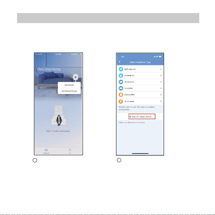
Network configuration by Bluetooth scan
Note: Make sure the bluetooth of your mobile device is working.
Press “ + Add Device ”
Press “Scan for nearby
devices”
1
2
16.Wireless control connection
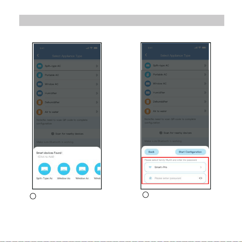
Wait smart devices to find,
then click to add it
Select home Wireless,
enter the password
3
4
58
16.Wireless control connection
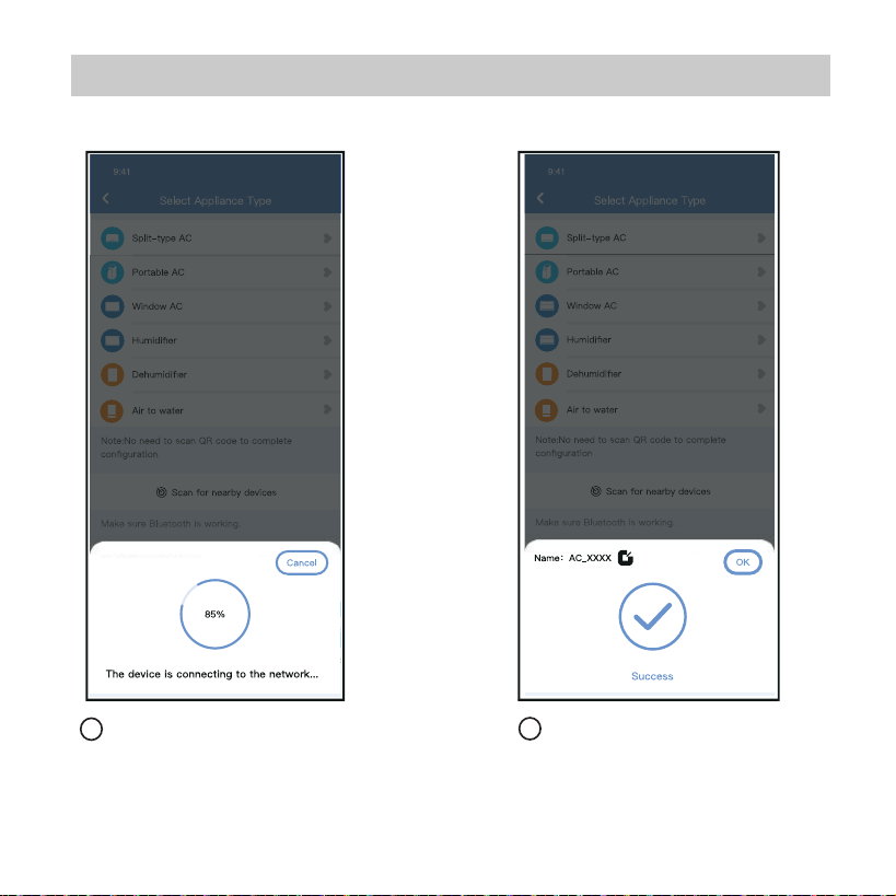
Wait connecting to the
network
5
6
Configuration Success,
you can modify the default
name.
59
16.Wireless control connection
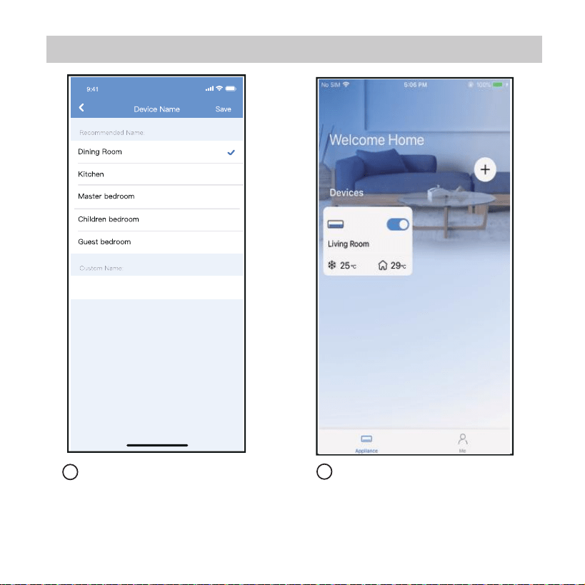
8
7
You can choose an
existing name or
customize a new name.
Bluetooth network
configuration is successful,
now you can see the
device in the list.
60
16.Wireless control connection

NOTE:
· Make sure your devices are powered on.
· Keep your mobile phone close enough to your device when you are
connecting network to your device.
· Connect your mobile phone to the wireless network at home, and
make sure you know the password of the Wireless Network.
· Check if your router supports 2.4 GHz Wireless Network band and
turn it on. If you are not sure whether the router supports 2.4 GHz
band, please contact the router manufacturer.
· The device cannot connect to the Wireless Network that requires
authentication, and it usually appears in public area such as hotels,
restaurants, etc. Please connect to a Wireless that does not require
authentication.
· It is recommended to use a Wireless Network name that only
contains letters and numbers. If your Wireless Network name
contains special characters, please modify it in the router.
· Turn o the WLAN+ (Android) or WLAN Assistant (iOS) function of
your mobile phone when connecting network to your devices.
· In the case that your device connected to Wireless Network before
but it needs to reconnect, please click "+" on app Home page, and
add your device again by the device category and model according
to the instructions on app.
61
16.Wireless control connection

APP DECLARATION
CAUTIONS:
This device complies with Part 15 of the FCC Rules and it contains
licence-exempt transmitter(s)/receiver(s) that comply with Innovation,
Science and Economic Development Canada’s licence-exempt RSS(s).
Operation is subject to the following two conditions:
(1) This device may not cause interference;and
(2) This device must acceptany interference,including interference
that may cause undesired operation of the device.
Only operate the device in accordance with the instructions supplied.
Changes or modications to this unit not expressly approved by the
party responsible for compliance could void the user's authority to
operate the equipment.
This device complies with FCC radiation exposure limits set forth for an
uncontrolled environment. In order to avoid the possibility of exceeding
the FCC radio frequency exposure limits, human proximity to the
antenna shall not be less than 20cm (8 inches) during normal operation.
Hereby, we declare that this Smart kit is in compliance with the essential
requirements and other relevant provisions of Directive 2014/53/EU.
A copy of the full DoC is attached.(European Union products only)
WirelessNetwork module models: US-SK107,EU-SK107:
FCC ID: 2ADQOMDNA21
IC: 12575A-MDNA21
62
16.Wireless control connection

NOTE:
This equipment has been tested and found to comply with the limits
for a Class B digital device, pursuant to part 15 of the FCC Rules.
These limits are designed to provide reasonable protection against
harmful interference in a residential installation. This equipment
generates, uses and can radiate radio frequency energy and, if not
installed and used in accordance with the instructions, may cause
harmful interference to radio communications. However, there is no
guarantee that interference will not occur in a particular installation.
If this equipment does cause harmful interference to radio or television
reception, which can be determined by turning the equipment o and
on, the user is encouraged to try to correct the interference by one or
more of the following measures:
--Reorient or relocate the receiving antenna.
--Increase the separation between the equipment and receiver.
--Connect the equipment into an outlet on a circuit dierent from
that to which the receiver is connected.
--Consult the dealer or an experienced radio/TV technician for help.
63
16.Wireless control connection
64
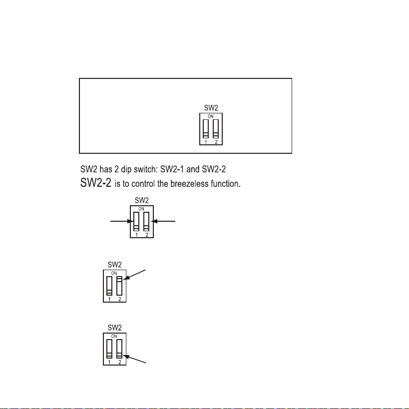
Breezeless function of dip switch.
NTOE: This feature is only available under cool mode.
This feature is for some models.
INDOOR UNIT MAIN BOARD
SW2-1
SW2-2
SW2-2 dip switch to be “ON”,turn on the breezeless.
SW2-2 dip switch to be “OFF”,turn off the breezeless.