
IMPORTANT NOTICE: Please read this manual carefully before installing or operating your wired remote
controller. Make sure to save this manual for future reference.
Installation &
Owner’s Manual
WIRED REMOTE CONTROLLER
MODEL
TST-MLD-I-WP24
Compatible with:
• RB, CB, UB, FB Fan Coil Units
• RYB, UYB, CYB, FYB Split Systems

This manual gives detailed description of the precautions
that should be brought to your attention during operation.
In order to ensure correct service of the wired controller
please read this manual carefully before using the unit.
For convenience of future reference, keep this manual
after reading it.
All the pictures in this manual are for explanation purpose
only. There may be slightly dierent from the wired remote
controller you purchased (depend on model). The actual
shape shall prevail.

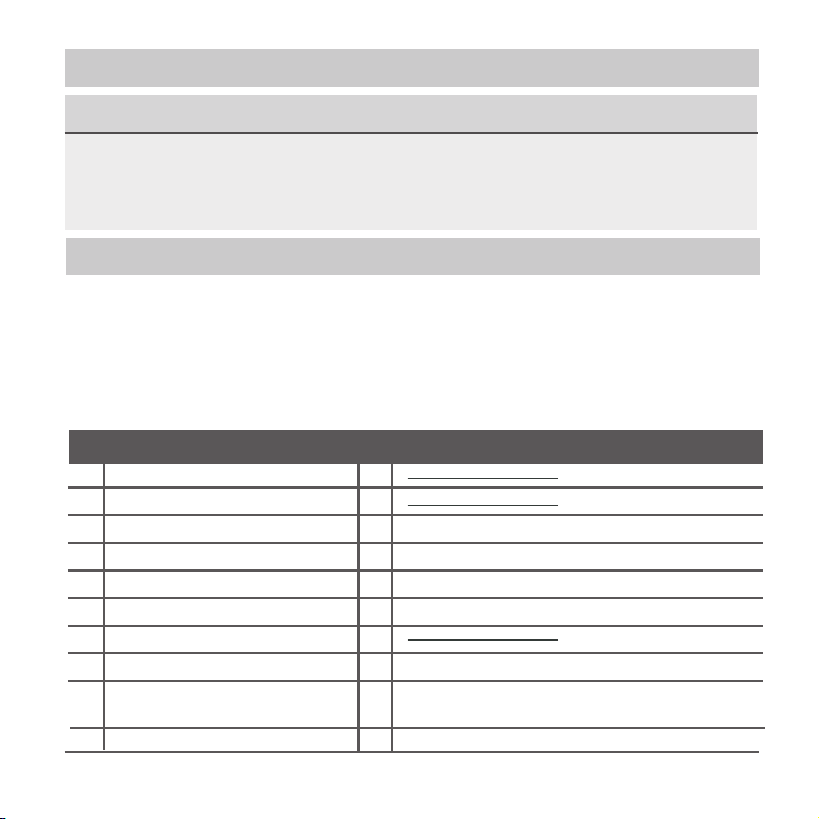
1. Safety precaution
2. Installation accessory
3. Installation method
4. Specification
5. Feature and function of the wired controller
6. Name on the LCD of the wired controller
7. Name of button on the wired controller
8. Preparatory operation
9. Operation
10. Timer functions
11. Weekly Timer 1
12. Weekly Timer 2
13. Fault alarm handing
14.Technical indication and requirement
15.Queries and settings
..........................................................1
................................................... 2
........................................................4
..................................................................9
................10
.....................11
.......................12
.................................................13
.....................................................................14
.........................................................20
..........................................................23
..........................................................29
...................................................36
.........................36
..................................................37
Table of Contents
1
1. Safety precaution
Do not uninstall the unit randomly.
Random uninstalling may lead to abnormal operation,
heating or re of the air condition.
Please entrust the distributor or professionals to install the unit.
Installation by other persons may lead to imperfect installation,
electric shock or re.
Adhere to this installation manual.
Imporper installation may lead to electric shock or re.
Reinstallation must be performed by professionals.
•
•
•
•
•
NOTE
Do not install the unit in a place vulnerable to leakage of
ammable gases.Once ammable gases are leaked and left
around the wire controller, re may occure.
Do not operate with wet hands or let water enter the wire
controller. Otherwise, electric shock may occur.
•
•
The wiring should adapt to the wire controller current.
Otherwise, electric leakage or heating may occur and result in
re.
•
WARNING
2
1. Safety precaution
NOTE
The specied cables shall be applied in the wiring. No external
force may be applied to the terminal. Otherwise, wire cut and
heating may occur and result in re.
•
2. Installation accessory
Don’t install at the place where cover with heavy oil, vapor or sulfureted
gas, otherwise, this product would be deformed that would lead to
system malfunction.
Select the installation location
Preparation before installation
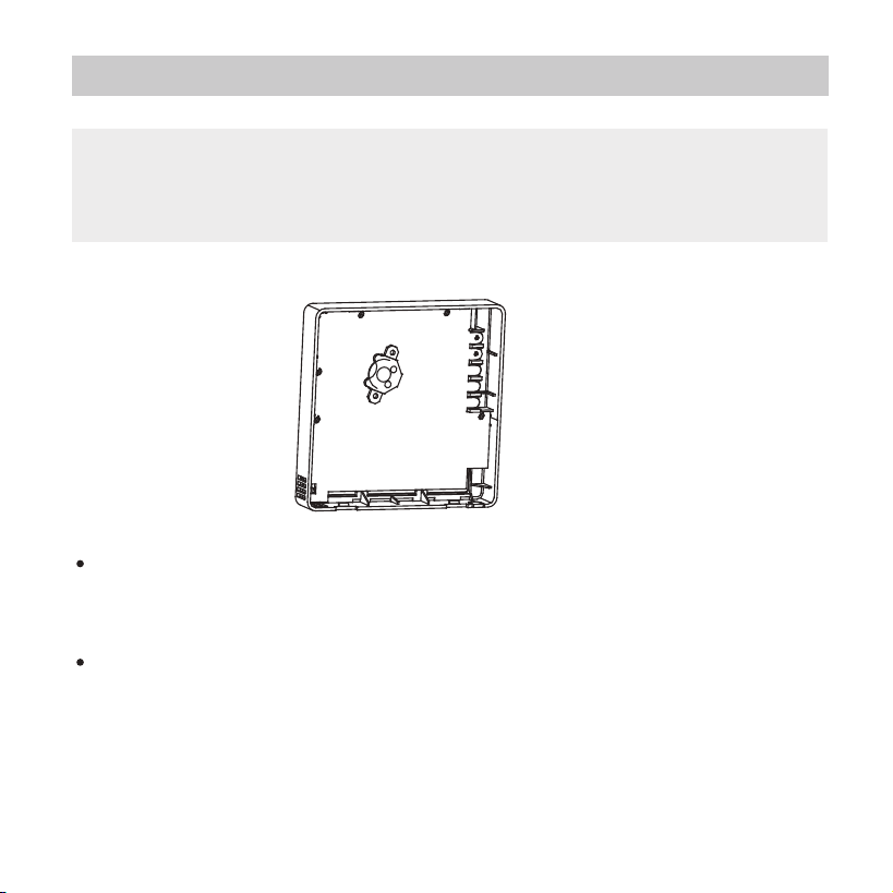
1. Please conrm that all the following parts you have been supply.
3
4
5
3
2
M3.9X25 (For Mounting on the Wall)
M4X25 (For Mounting on switch box)
6
7
8
3
2
No. Name Qty. Remarks
For Mounting on the Wall
Plastic screw bars
Screws
Wall plugs
For xing on switch box
Optional
Screws
2
Installation and owner’s manual
1
1
Wire controller
1
Battery
The connective wires group
1
1
9
Screw(
Only available for the shielded
wire with connection plug
)
1
M4X8(For Mounting the connective wire group)
10
Magnetic ring
1
Use the magnetic ring to hitch the connective cable of the wire controller.
3
2. Installation accessory
Precaution of installing the wire controller
1. This manual provides the installation method of wired
controller. Please refer to the wiring diagram of this installation
manual to connect the wire controller with indoor unit.
2. The wired controller works in low voltage loop circuit. Forbid
to directly contact the cable of high voltage above,like 115V,
220V,380V, and don’t wire this kind of wire in the
said loop; wiring clearance between congured tubes should
be at the range of 300~500mm or above.
3. The Shielded wire of the wired controller must be grounded
rmly.
4. Upon nish the wire controller connection, do not employed
tramegger to detect the insulation.
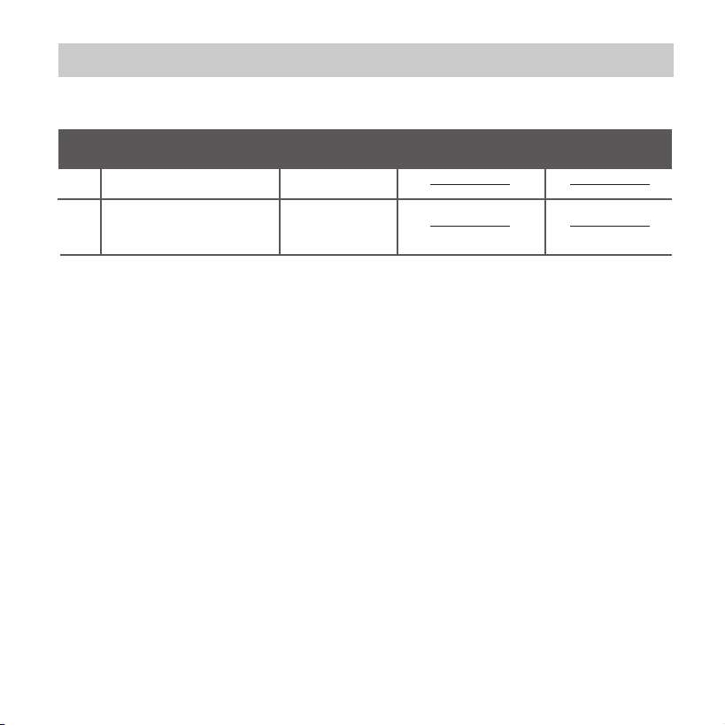
2. Prepare the following assemblies on the site.
1
2
1
Switch box
Wiring Tube(Insulating
Sleeve and Tightening
Screw)
Qty.(embeded
into wall)
No.
Name
Remarks
Specification
(only for reference)
1
4
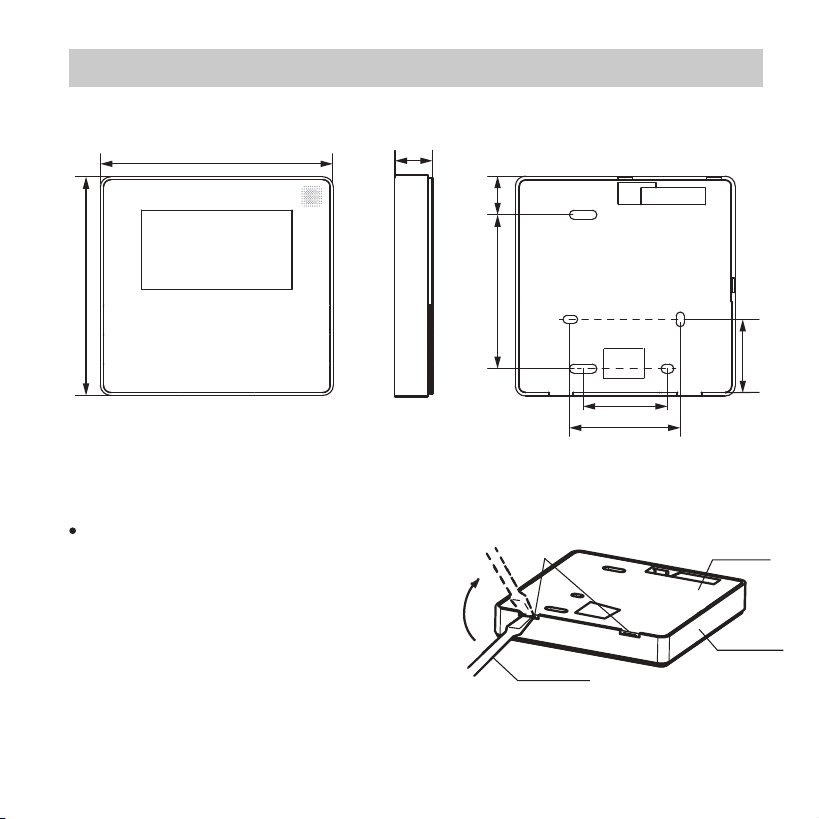
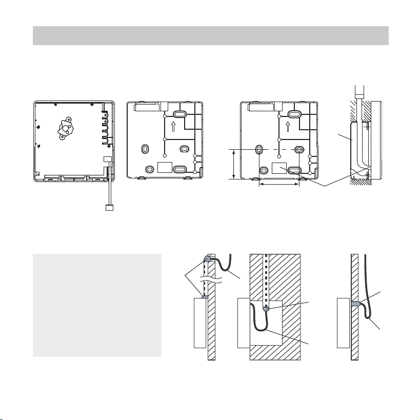
3. Installation method
Fig 3-2
Fig 3-1
1.Wired remote controller structural dimensions
2.Remove the upper part of wired controller
Insert a slot screwdriver into the
slots in the lower part of the wired
controller (2 places), and remove
the upper part of the wire
controller. (Fig.3-2)
19mm84mm
46mm
60mm
44mm
120mm
120mm
20mm
Buckling
position
Back cover
Straight head
screwdriver
Front cover
5
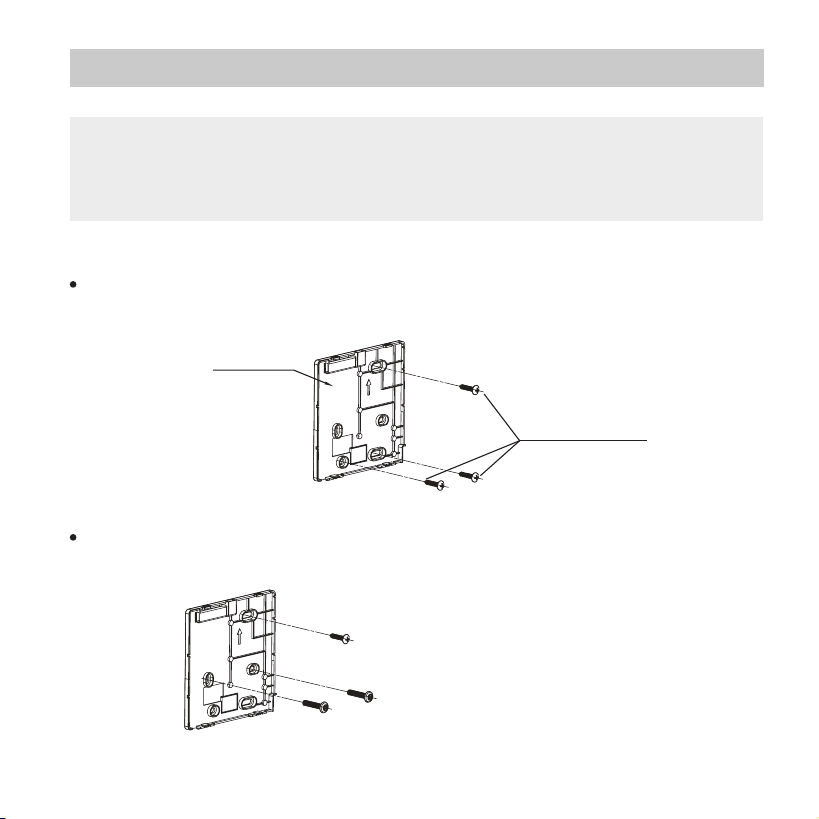
3. Installation method
Fig 3-3
Fig 3-4
For exposed mounting, fasten the back plate on the wall with
the 3 screws (M4×20) and plugs. (Fig.3-3)
Use two M4X25 screws to install the back cover on the 86
switch box, and use one M3.9X25 screw to x to the wall.
3. Fasten the back plate of the wired controller
Back plate
Screws (M4×20)
Screw hole xed on the wall,useone φ3.9X25mm
Screw hole installed on 86 switch box, use two M3.9X25mm
NOTE: The PCB is mounted in the upper part of the wired
controller. Be careful not to damage the board
with the slot screwdriver.
6
3. Installation method
Put the battery into the installationsite and make sure the
positive side of the battery is in accordance with the
positive side of installationsite.(See Fig.3-5)
Please set the time corrected on the rst time operation.
Batteries in the wire controller can time under power
failure which ensure the time keep right. When the power
restores, if the time displayed is not correct, it means the
battery is dead and replace the battery.
Fig 3-5
4. Battery installation
NOTE: Put on a at surface. Be careful not to distort the
back plate of the wire controller by overtightening the
mounting screws.
7
3. Installation method
Fig 3-6
5. Wire with the indoor unit
Fig 3-7
Putty
Putty
Putty
Trap
Trap
Trap
1 indoor unit
2 notch the part for the wiring to pass through with nippers, etc.
NOTE: DO NOT
allow water to enter
the remote control.
Use the trap and
putty to seal the
wires.
44mm
60mm
Wiring
hole
switch box
A
B
1. Safety precaution
2. Installation accessory
3. Installation method
4. Specification
5. Feature and function of the wired controller
6. Name on the LCD of the wired controller
7. Name of button on the wired controller
8. Preparatory operation
9. Operation
10. Timer functions
11. Weekly Timer 1
12. Weekly Timer 2
13. Fault alarm handing
14.Technical indication and requirement
15.Queries and settings
..........................................................1
................................................... 2
........................................................4
..................................................................9
................10
.....................11
.......................12
.................................................13
.....................................................................14
.........................................................20
..........................................................23
..........................................................29
...................................................36
.........................36
..................................................37
8
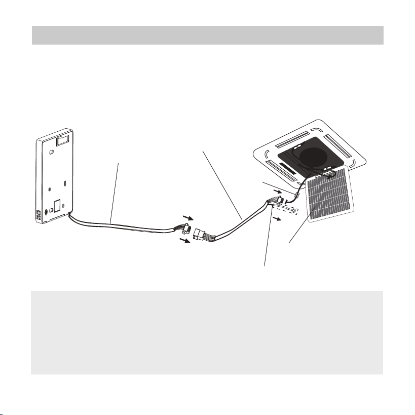
3. Installation method
6.Installation Diagram
Connect the wire from the master control board of the indoor
unit to a connecting cable. Then connect the other side
of the connecting cable to the remote control.
NOTE:
Be sure to reserve a length of the connecting
wire for periodic maintenance.
If there is a connection lug at the end of shielded wire,
the connection lug should be properly grounded.
4-core wire
The connective wires group
Front grille
shielded wire(some units)
Fig. 3-8
Magnetic
ring
9
3. Installation method
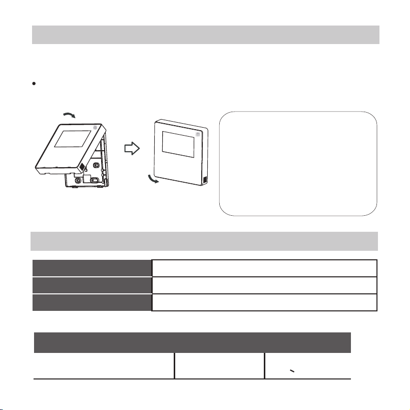
4. Specification
Fig 3-9
7. Reattach the upper part of the wire controller
After adjusting the upper case and then buckle the upper case;
avoid clamping the wiring during installation. (Fig 3-9)
Wiring specications
Wiring type
Size
Total length
shielded vinyl cord or cable 0.5-1.25mm
<50m(164’)
2
All the pictures in this
manual are for
explanation purpose only.
Your wire controller may
be slightly dierent .The
actual shape shall prevail.
KJR-120X1/TFBG-E: DC 5V, KJR-120X2/TFBG-E: DC 12V
-5~43℃(23~110℉)
RH40%~RH90%
Input voltage
Ambient temperature
Ambient humidity
10
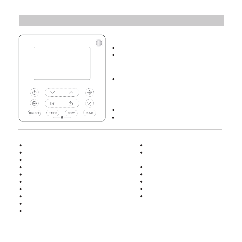
5. Feature and function of the wired controller
Feature:
LCD display.
Malfunction code display: it can
display the error code, helpful
for service.
4-way wire layout design, no raised
part at backside, more convenient
to place the wires and install the
device.
Room temperature display.
Weekly Timer.
Function:
Mode: choose Auto-Cool-Dry- Heat -Fan
Fan speed: Auto/Low/Med/High speed
Swing(on some models)
Timer ON/OFF
Temp setting
Weekly timer
Follow me
Turbo
24-hour System
12-hour System
Auto-restart
Individual louver control
(on some models)
Automatic airow test
Child Lock
LCD display
Clock
Panel function
(on some models)
-------
-------
----
----
11
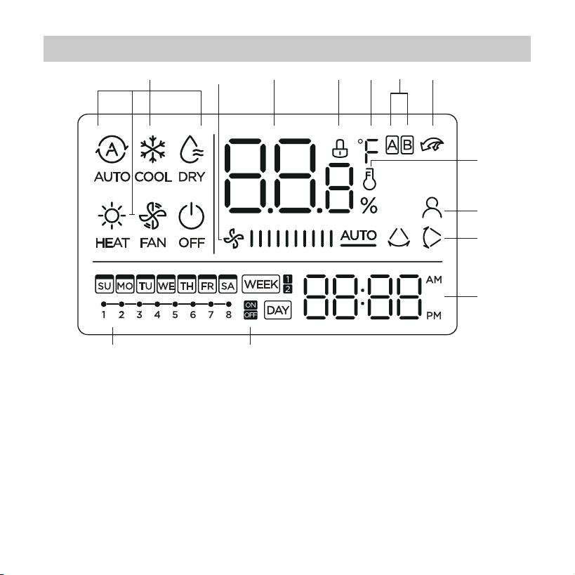
6. Name on the LCD of the wired controller
1 Operation mode indication
2 Fan speed indication
3 Temperature display
4 Lock indication
5 °C / °F indication
6 Main unit and secondary
unit indication
7 Turbo function indication
1 2 3 4 5 7
8
9
10
11
1213
8 Room temperature indication
9 Follow Me function indication
10 Left-right swing indication
(some models)
11 Clock display
12 On/O timer
13 Timer display
6
12
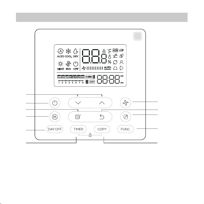
7. Name of button on the wired controller
1 POWER button
2 MODE button
3 DAY OFF/DEL button
4 ADJUST button
5 CONFIRM button
6 TIMER button
7 FAN SPEED button
8 BACK bottom
9 SWING bottom
10 FUNC. button
11 COPY button
3
1
2
10
7
9
4
5
6
11
8
13
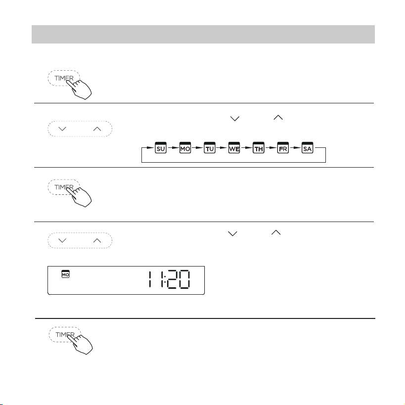
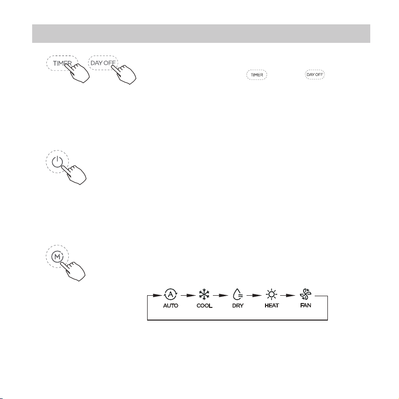
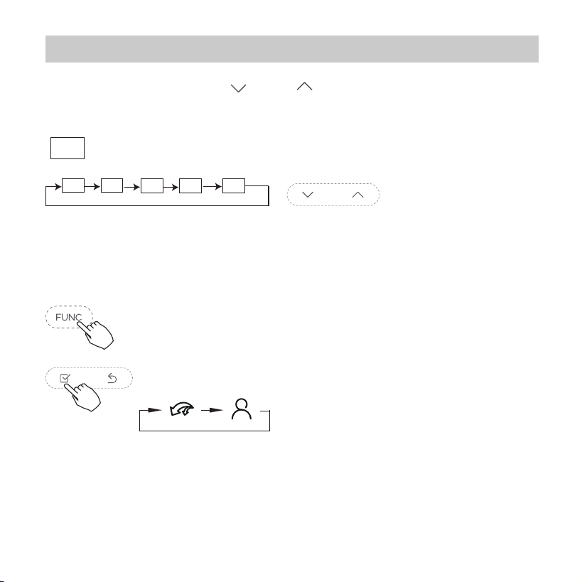
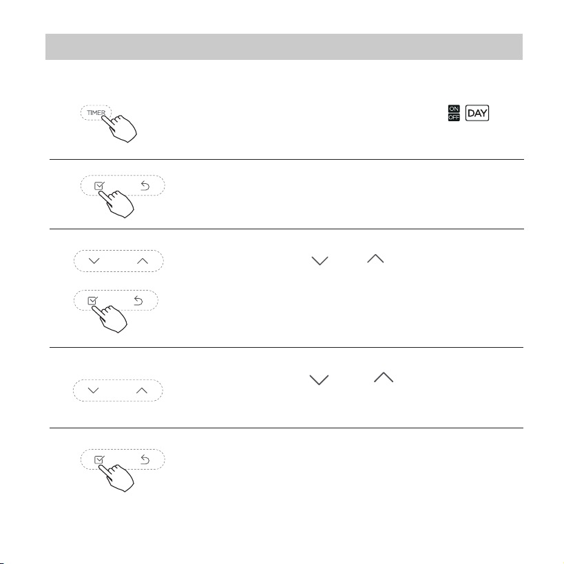
Press the Timer button for 2 seconds or more.
The timer display will ash.
1
2
3
4
The date setting is nished and the time setting is
prepared after pressing Timer button or CONFIRM
button or there is no pressing button in 10 seconds.
The setting is done after pressing CONFIRM
button or there is no pressing button in 10
seconds.
Set the current day and time
8. Preparatory operation
5
ex.Monday 11:20
Press the button “ ” or “ ” to set the date.
The selected date will ash.
Press the button “ ” or “ ” to set the
current time. Press repeatedly to adjust the
current time in 1-minute
increments. Press and hold
to adjust the current time
continuous.
14
9. Operation
To start/stop operation
Press the Power button.
To set the operation mode
Press the Mode button to set the
operation mode.(Heat function is invalid
for cool only type unit)
Operation mode setting
6
Time scale selection
Press the buttons “ ” and “ ” for 2
seconds will alternatethe clock tieme
display between the 12h&24h scale.
15
9. Operation
Room temperature setting
Lower Raise
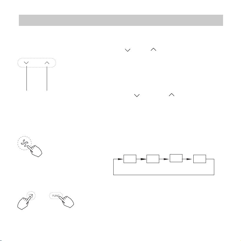
Fan speed setting
Press the Fan speed button to set the fan speed.
(This button is unavailable when in the mode of
Auto or Dry)
Auto LOW MED HIGH
keypad tone setting
Press the buttons Swing and FUNC. for 3
seconds to close the keypad tone.
Press the buttons again for 3 seconds to
open the keypad tone.
Press the button“ ”or “ ” to set the room
temperature.
Indoor Setting Temperature Range :
17~30°C(62~86°F ).
°C & °F scale selection(on some models)
Press the buttons “ ” and “ ” for 3 seconds
will alternate the temperature display between
the °C & °F scale.
16
9. Operation
Child lock function
2 Left-Right swing
Press the Swing button long to start Left-Right swing function.
Press it again to stop. When the Left-Right swing function is
activated, the mark appears.
1 Up-Down swing
Press the SWING button to start up-down swing
function. Press it again to stop.
When the Up-Down swing function is activated,the
mark appears.
Swing function(For the unit left & right auto swing
models only)
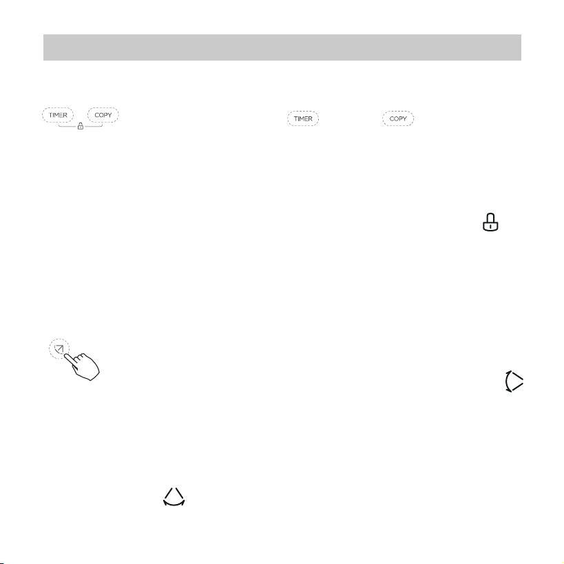
Press the buttons “ ” and “ ” for 3
seconds to activate the child lock function and lock
all buttons on the wire controller.
Press the buttons again for 3 seconds to
deactivate the child lock function.
When the child lock function is activated,the
mark appears.
17
9. Operation
Up-Down airow direction and swing
The operation can refer to the following instructions for the
unit with four Up-Down louvers can be operated individually.
Swing function(For the unit without left & right auto
swing function models)
1.Press the button every time, the louver swings 6 degrees.
2.Press and hold the button for 2 seconds,it turns into up-down
swing mode,press ti again to stop. When the Up-Down swing
function is activated,the mark appears. (Not applicable
to all the models)
Use Swing button to adjust the Up-down airow
direction.
1.Press the Swing button to activate the Up-Down
adjusting louver function.
The mark will ash.(Not applicable to all the models)
18
2.Pressing the button “ ” or“ ” can select the movement
of four louvers.Each time you push the button,the wire
controller select in a sequence that goes from:(the icon
means the four louvers move at the same time.)
9. Operation
3. And then use Swing button to adjust the Up-Down airow
direction of the selected louver.
-0
-1
-2
-3
-4
-0
Press the FUNC. button to set the turbo or Ifeel
function.
The select function icon will ash then press the
Conrm button to conrm the setting.
19
9. Operation
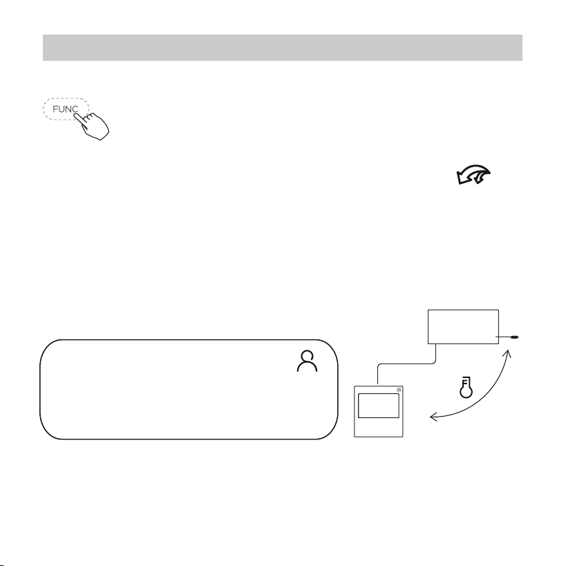
Press the button again to cancel the follow me function.
Indoor Unit
Press the FUNC. button to select whether
the room temperature is detected at the indoor
unit or the wire controller.
Follow me function indication
Turbo function (on some models)
Under COOL/HEAT mode ,press the FUNC. button
to activate the turbo function. Press the button
again to deactivate the turbo function.
When the turbo function is activated,the
mark appears.
When the follow me function
indication appears,the room
temperature is detected at the wire
controller.
20
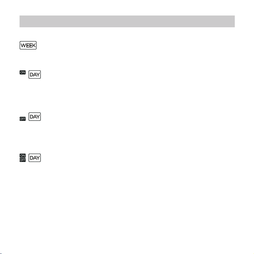
WEEKLY timer
Use this timer function to set operating times for each
day of the week.
On timer
Use this timer function to start air conditioner operation.
The timer operatesand air conditioner operation starts
after the time has passed.
O timer
Use this timer function to stop air conditioner operation.
The timer operates and air conditioner operation stops
after the time has passed.
On and O timer
Use this timer function to start and stop air conditioner
operation.The timer operates and air conditioner
operation starts and stops after the time has passed.
10. Timer functions
21
10. Timer functions
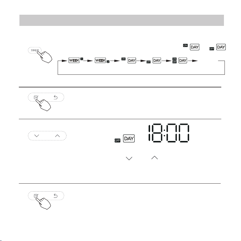
To set the On or Off TIMER
No display
1
2
Press the Conrm button and the Timer display
is ashing.
Press the Conrm button again to nish the
settings.
3
ex.O timer set at 18:00
4
Press the button “ ” or “ ” to set the time.
After the time is set, the timer will start or stop
automatically.
Press the Timer button to select the or .
22
10. Timer functions
Press the Conrm button to nish the settings.
To set the On and Off TIMER
Press the Timer button to select the .
1
2
Press the Conrm button and the Clock display
is ashing.
3
Press the button “ ” or “ ” to set the time
of On timer,and then press the Conrm button
to conrm the setting.
4
5
Press the button “ ” or “ ” to set the time
of O timer.
23
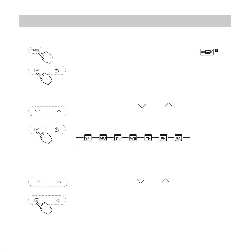
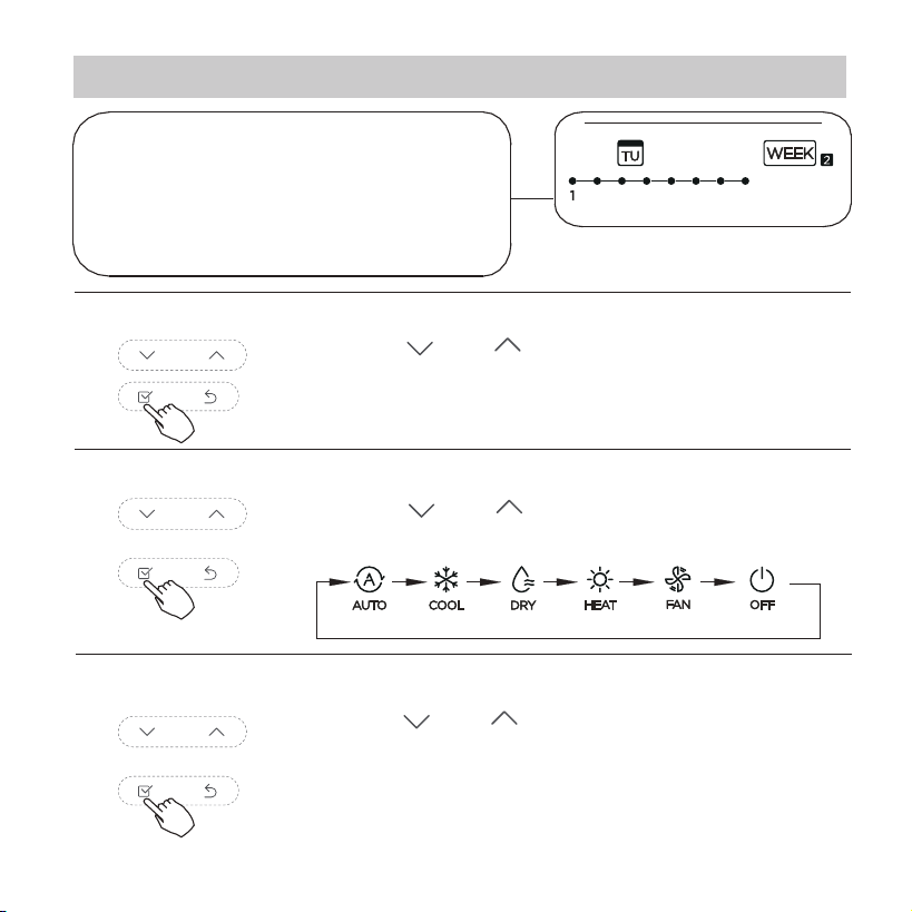
11. Weekly Timer 1
Press the Timer button to select the
and then press the Conrm button to conrm.
Weekly timer setting
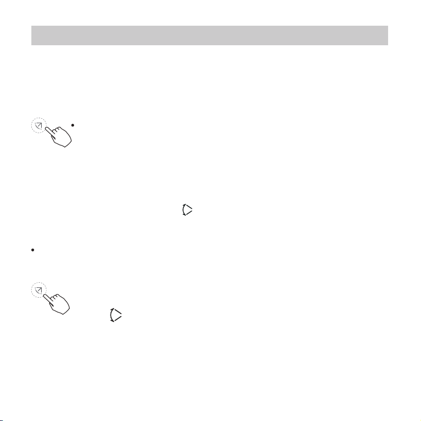
1
Press the button “ ” or “ ” to select the day
of the week and then press the Conrm button
to conrm the setting.
2
Day of the week setting
Press the button “ ” or “ ” to set the time of
On timer and then press the Conrm button to
conrm the setting.
ON timer setting of timer setting 1
3
24
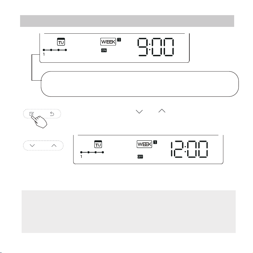
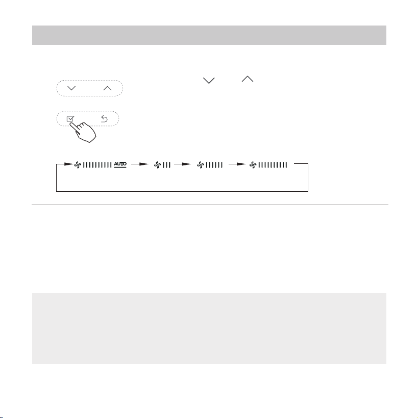
11. Weekly Timer 1
ex.Tuesday time scale 1
Dierent timer settings can be setted by repeating step 3 to 4.
Other days in one week can be setted by repeating step 2 to 5.
4
Off timer setting of timer setting 1
5
6
ex.Tuesday time scale 1
Press the button “ ” or “ ” to set the time of
O timer and then press the Conrm button to
conrm the setting.
NOTE: The weekly timer setting can be returned to the
previous step by pressing Back button.The time of timer
setting can be delete by pressing Day o botton The current
setting will be restored and withdrawn the weekly timer setting
automatically when there is no operation for 30 seconds.
Up to 4 timer settings can be saved for each day of the
week.It is conventent if the WEEKLY TIMER is set
according to the user’s life style.
25
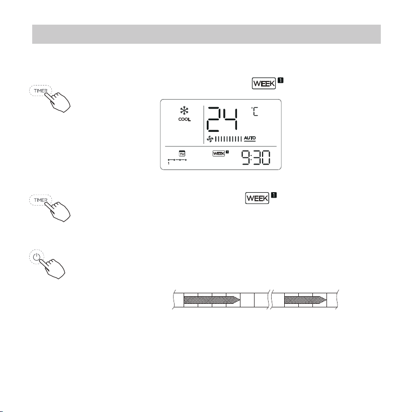
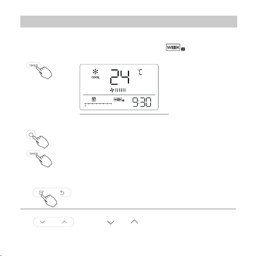
11. Weekly Timer 1
To activate WEEKLY TIMER operation
WEEKLY timer operation
ex.
To deactivate WEEKLY TIMER operation
To turn off the air conditioner during the weekly timer
1. If press the Power button once and quickly , the air
conditioner will turn o temporarily. And the air
conditioner will turn on automatically until the time
of On timer.
ON OFF ON OFF
8:00 12:00 14:00 17:0010:00
ex. If press the POWER button once and quickly at 10:00,
The air conditioner will turn on at 14:00.
2. When press the Power button for 2 seconds , the air
conditioner will turn o completely,at the same time
cancel the timing function.
Press the Timer button while is displayed
on the LCD.
Press the Timer button while is disappear from
the LCD.
26
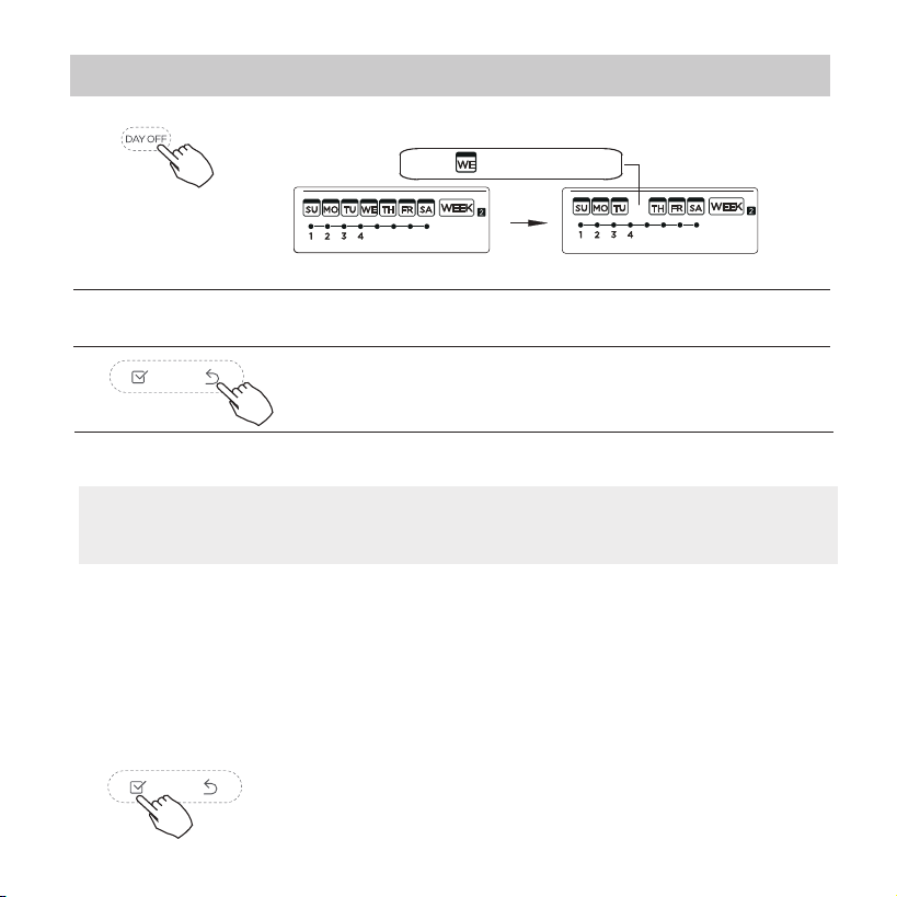
11. Weekly Timer 1
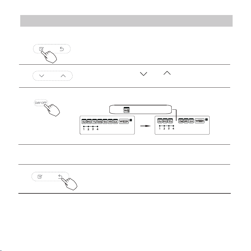
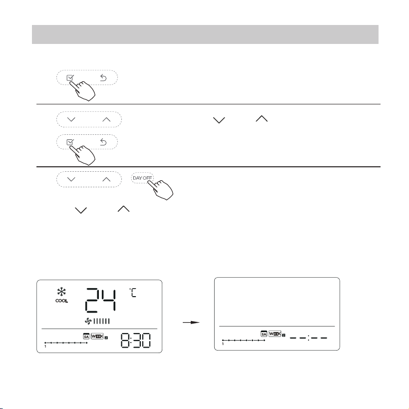
To set the DAY OFF (for a holiday)
During the weekly timer, press the Conrm
button.
1
2
Press the Back button to back to the weekly
timer.
Press the Day o button to set the DAY OFF.
3
5
To cancel:Follow the same procedures as those for setup.
4
ex.The DAY OFF is set for Wednesday
The DAY OFF can be setted for other days by
repeating the steps 2 and 3.
The mark is hidden
Notes:
The DAY OFF setting is cancelled automatically after the set
day has passed.
Press the button “ ” or “ ” to select the day
in this week .
27
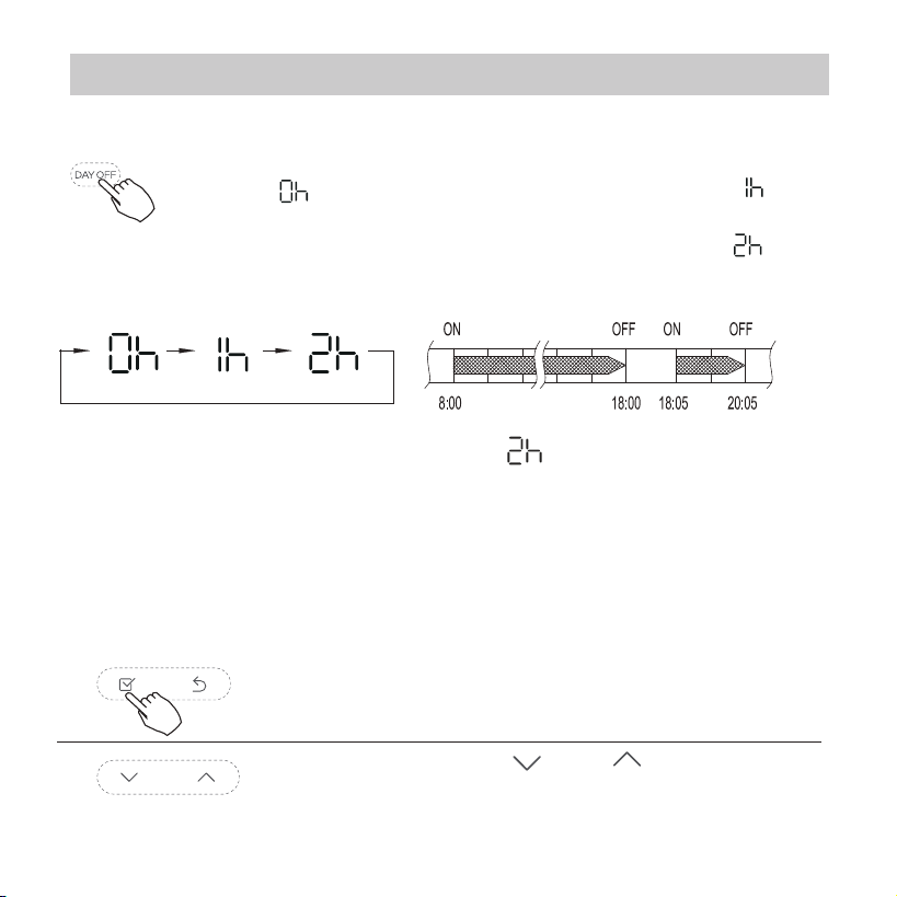
DELAY function
Copy out the setting in one day into the other day.
During the weekly timer, press the Conrm
button.
1
A reservation made once can be copied to another day of the
week.The whole reservation of the selected day of the week will
be copied. The eective use of the copy mode ensures ease of
making reservations.
2
Press the button “ ” or “ ” to select the
day to copy from.
During the weekly timer, pressing the Del button once,
display " ". Press this button twice, display " " and
wait 3 seconds to conrm. It means the unit will override
1 hours; Press this button three times,display " " and
wait 3 seconds to conrm. It means the unit will override
2 hours;
ex. If press the DEL button to select “ ” at 18:05 ,
The air conditioner will delay to turn o at 20:05.
11. Weekly Timer 1
28
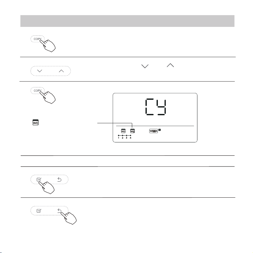
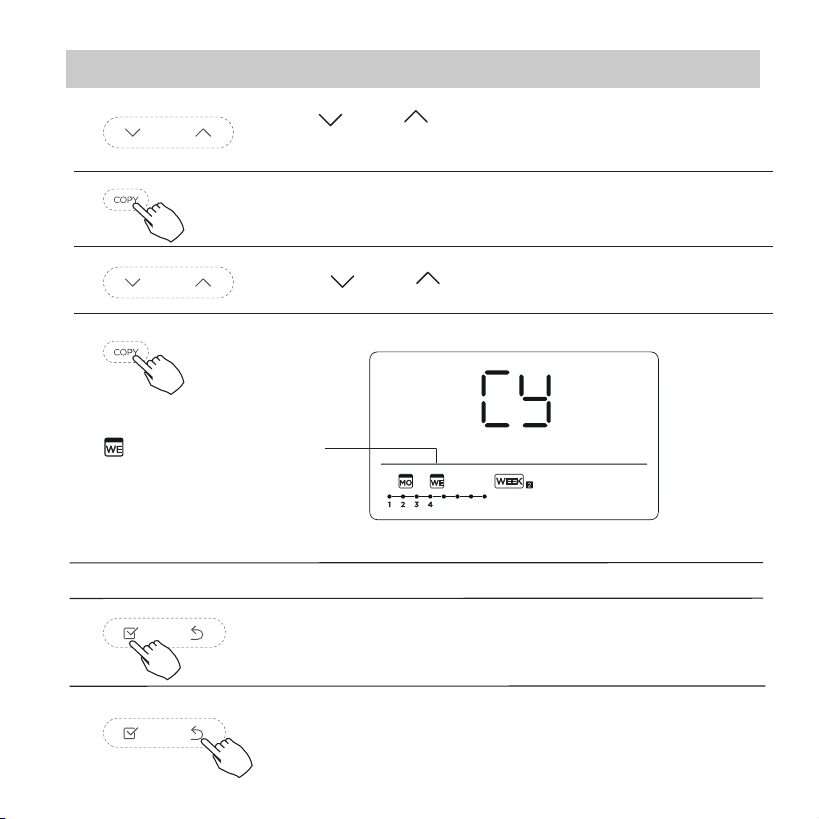
Press the Copy button,the letter “CY” will be
shown on the LCD.
3
4
Press the button “ ” or “ ” to select the day
to copy to.
Press the Conrm button to conrm the
settings.
Press the Back button to back to the weekly
timer.
5
Press the Copy button to conrm .
Other days can be copied by repeating step 4 and 5.
ex. Copy the setting of Monday to Wednesday
The mark ashes quickly
6
7
8
11. Weekly Timer 1
29
Press “ ” or “ ” to select the setting
time. The setting time, mode, temperature
and fan speed appear on the LCD. Press
CONFIRM to enter the setting time process.
Press “ ” or “ ” to select the day of the
week and then press CONFIRM.
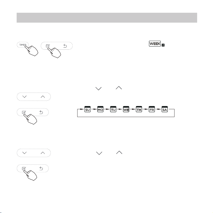
12. Weekly Timer 2
Weekly timer setting
1
Press Timer to select the and press
Conrm.
2
Day of the week setting
ON timer setting of timer setting 1
3
30
Press “ ” or “ ” to set the room
temperature then press CONFIRM.
NOTE: This setting is unavailable in the FAN
or OFF modes.
Press “ ” or “ ” to set the operation
mode then press CONFIRM.
Press “ ” or “ ” to set the time then press
CONFIRM.
12. Weekly Timer 2
ex.Tuesday time scale 1
IMPORTANT: Up to 8 scheduled
events can be set on one day.
Various events can be scheduled
in either MODE, TEMPERATURE
and FAN speeds.
4
Time setting
5
Operation mode setting
6
Room temperature setting
31
12. Weekly Timer 2
Press “ ” or “ ” to set the fan speed
then press CONFIRM.
NOTE: This setting is unavailable in the
AUTO, DRY or OFF modes.
7
Fan speed setting
Different scheduled events can be set by repeating
steps 3 through 7.
8
Additional days, in a one week period, can be set by
repeating steps 3 through 8.
9
NOTE:
The weekly timer setting can be returned to the
previous step by pressing BACK. The current setting is
restored. The controller will not save the weekly timer
settings if there is no operation within 30 seconds.
32
12. Weekly Timer 2
To start
WEEKLY timer operation
Press Timer to select the , and then the
timer starts automatically.
ex.
To cancel
The timer mode can also be canceled by
changing the timer mode using Timer.
Press the Power buttons for 2 seconds to
cancel the timer mode.
To set the DAY OFF (for a holiday)
After setting the weekly timer, press CONFIRM.
1
Press “ ” or “ ” to select the day of the
week.
2
33
NOTE:
The DAY OFF setting is cancelled automatically after
the set day has passed.
The mark is hidden
12. Weekly Timer 2
Press BACK to revert to the weekly timer.
Press DAY OFF to create an o day.
3
5
To cancel, follow the same procedures used for setup.
4
ex.The DAY OFF is set for Wednesday
Set the DAY OFF for other days by repeating the steps 2 and 3.
Copy out the setting in one day into the other day.
In the weekly timer, press CONFIRM.
1
A scheduled event, made once, can be copied to another day of
the week. The scheduled events of the selected day of the week
will be copied. The eective use of the copy mode ensures the
ease of reservation making.
34
12. Weekly Timer 2
Press COPY, the letters CY appear on the LCD.
3
4
Press CONFIRM to conrm the settings.
Press BACK to revert to the weekly timer.
5
Press COPY to conrm.
Other days can be copied by repeating steps 4 and 5.
ex. Copy the setting of Monday to Wednesday
The mark ashes quickly
6
7
8
Press “ ” or “ ” to select the day to copy to.
2
Press “ ” or “ ” to select the day to copy
from.
35
12. Weekly Timer 2
Delete the time scale in one day.
During the weekly timer setting, press
CONFIRM.
1
2
Press “ ” or “ ” to select the day
of the week and then press CONFIRM.
Press “ ” or “ ” to select the setting time want to delete. The
setting time, mode, temperature and fan speed appear on the
LCD. The setting time, mode, temperature and fan speed can be
deleted by pressing the DEL (day o).
3
ex. Delet the time scale 1 in saturday
36
14.Technical indication and requirement
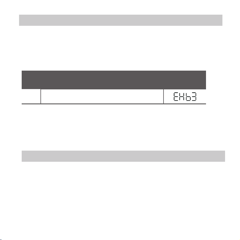
13. Fault alarm handing
If the system does not properly operate except the above
mentioned cases or the above mentioned malfunctions is
evident, investigate the system according to the following
procedures.
The error displayed on the wire controller are dierent from
those on the unit. If error code appears, please check the
<<Owner’s And Installation Manual>>and<<SERVICE
Manual>>.
EMC and EMI comply with the CE certication
requirements.
MALFUNCTION & PROTECTION DEFINE
DISPLAY
DIGITAL TUBE
NO.
1
Error of communication between wire controler
and indoor unit
37
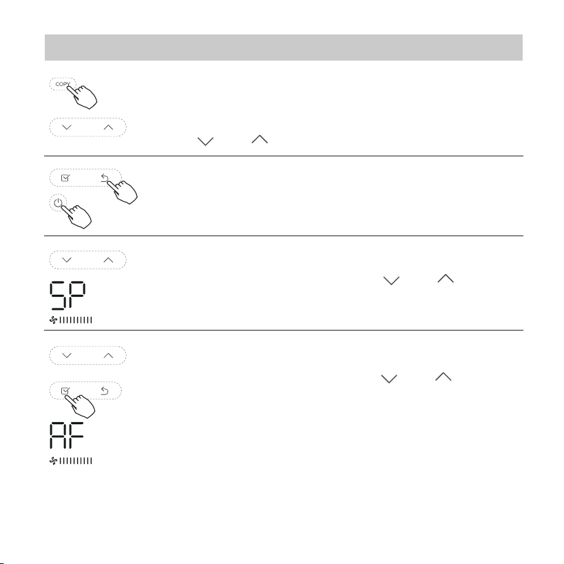
15.Queries and settings
Not operating keys 15 seconds or press “Back” or
press “ON/OFF”drop out of query temperature.
When the air conditioning unit is switch machine,
Long press “COPY” for 3 seconds to enter a query
indoor unit Tn(T1~T4) temperature and fan fault(CF),
press“ ”or “ ”to select.
When the air conditioning unit is o, into the query
function of temperature, press“ ” or “ ”to select
SP, press “Conrm” to adjust the static pressure value.
When the air conditioning unit is o, into the query
function of temperature, press“ ”or “ ”to select
AF, press “Conrm” into test mode, press “Back” or
press “ON/OFF” or press “Conrm”drop out of test
mode.
In AF mode, 3~6 minutes test completion
automatically exits, if the test process, press “Back” or
press “ON/OFF”or press “Conrm” , the test exits will
be interrupted.
38
15.Queries and settings
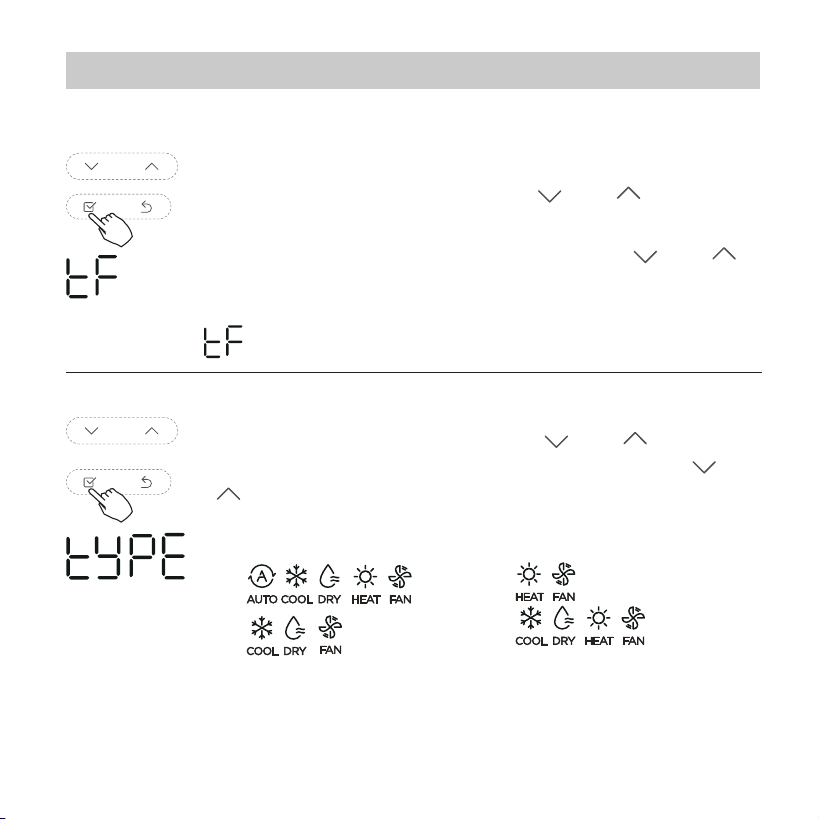
When the air conditioning unit is o, into the query
function of temperature, press“ ”or “ ”to select tF.
The compensation temperature Range : -5
°C
~5
°C
.
Press “Conrm” into setting state, press“ ”or “ ”
to select the temperature, then press “Conrm” to
complete it.
: compensation temperature
Follow me function temperature compensation
When the air conditioning unit is o, into the query
function of temperature, press“ ”or “ ”to select
tyPE. Press “Conrm” into setting state, press“ ”or
“ ”to select the type, then press “Conrm” to
complete it.
CH:
CC:
HH:
NA:
39
15.Queries and settings
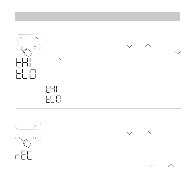
When the air conditioning unit is o, into the query
function of temperature, press“ ”or “ ”to select
rEC. ON or OF will be displayed in the temperature
area to indicate whether it is valid or invalid.
When the selection is invalid, the wire controller
does not process any remote control signals.
Press “Conrm” into setting state, press“ ”or “ ”to
select , then press “Conrm” to complete it.
When the air conditioning unit is o, into the query
function of temperature, press“ ”or “ ”to select
tHI or tLo. Press “Conrm” into setting state, press“ ”
or “ ”to select the temperature, then press “Conrm”
to complete it.
The highest setting temperature range : 25
°C
~30
°C
The lowest setting temperature range: 17
°C
~24
°C
.
: Highest value setting function.
: Minimum value setting function.
Remote control function selection of wire controller
Set the highest and lowest temperature values
40
15.Queries and settings
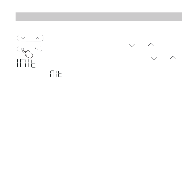
After the wire controller resumes the factory parameter setting,
compensation of body temperature is uncompensated; COOL
and HEAT/single COOL mode is restored to COOL
and HEAT model; The temperature range was restored to
17 °C~30°C. Remote receiving function is restored to be
eective.
Restore factory Settings
: Restore factory Settings .
When the air conditioning unit is o, into the query
function of temperature, press“ ”or “ ”to select
INIt, the temperature zone displayed --.
Press “Conrm” into setting state, press“ ”or “ ”to
select to "ON" , then press “Conrm” to complete it.

The design and specications are subject to change without
prior notice for product improvement.Consult with the sales
agency or manufacturer for details.