
Repair Guide
Basic Model
HW-C450/ZC
Applicable Model
HW-C4****
Ver .1.0

NOTICE TO QUEBEC CONSUMERS – Warranty of Availability of Replacement
Parts, Repair Services, and Maintenance and Repair Information
Replacement Parts
Although Samsung Canada will use reasonable efforts to make replacement parts available to customers
(subject to availability and applicable lead times), Samsung Canada does not guarantee
the availability of
replacement parts within the meaning of the warranty of availability set out in sections 39 (paragraph 3),
39.1 and 39.2 of the Quebec Consumer Protection Act.
To purchase replacement parts and tools for self-repair, please visit:
samsung.com/ca/support/buy-
certified-parts
Repair Services
Although Samsung Canada offers repair services for Samsung products through Samsung Authorized
Service Centers located in most major urban centers (defined as a city in Canada with a population equal
or greater than 50,000) across Canada, Samsung Canada does not guarantee
the availability of any repair
services within the meaning of the warranty of availability set out in sections 39 (paragraph 3), 39.1 and
39.2 of the Quebec Consumer Protection Act in all locations, cities, or regions in Quebec.
To find your nearest Samsung Authorized Service Center, please visit:
samsung.com/ca/support/service-
center
Information for Maintenance or Repair
Although Samsung Canada provides information on the maintenance and/or repair of goods for select
Samsung products (please visit
samsung.com/ca/support/self-repair for more information), Samsung
Canada does not guarantee
the availability of information that is necessary to maintain or repair
Samsung products within the meaning of the warranty of availability set out in sections 39 (paragraph 3),
39.1 and 39.2 of the Quebec Consumer Protection.

DISCLAIMER OF LIABILITY
Samsung is not liable for any damage or defect determined to be caused by repair by a non-authorized
service provider, self-repair or non-professional repair of the product. Samsung is not liable for any
resulting damage to the product, person, or property, or any injury or other product safety issue caused
by or resulting from any repair, or any attempt to repair, any diagnosis, maintenance, or modification
performed by any person, including, but not limited to, any of the following: (i) any indirect, incidental,
special, or consequential damages (including but not limited to, damage to or loss of personal or
commercial property, damage to reputation, loss of use, cost of purchase of replacement goods, etc.);
(ii) any loss of data, goodwill, privacy, or profits or loss of business opportunity; and (iii) any inability to
use, or reduced functionality of, the product. Any damage or defect to product resulting from a repair,
or an attempt to repair, the product by any person (other than a Samsung certified service provider) will
not be covered by the warranty. Samsung’s liability shall be limited to the greatest extent permitted by
law.
This manual contains confidential and proprietary information of Samsung Electronics Co., Ltd. (“Samsung
Korea”, and, together with its affiliates and subsidiaries “Samsung”).
Samsung provides these manuals to individual consumers for Self-Repair purposes and to independent
repair entities.
All text, graphics, user interfaces, visual interfaces, photographs, trademarks, and logos (collectively,
"Content"), including but not limited to the design, structure, selection, coordination, "look and feel" and
arrangement of such Content, contained in this manual is owned, controlled or licensed by or to Samsung,
and is protected by trade dress, copyright, patent and trademark laws, and various other intellectual
property rights and unfair competition laws.
No part of this manual or the Content may be copied, reproduced, republished, uploaded, posted, publicly
displayed, encoded, translated, transmitted or distributed in any way (including "mirroring") to anyone,
any entity, any other computer, server, Web site or other medium for publication or distribution or for any
commercial purpose, without Samsung’s express prior written consent.
Limitation of Liability. WHILE SAMSUNG MAKES ALL REASONABLE EFFORTS TO ENSURE THAT ALL
INFORMATION IN THIS MANUAL IS CORRECT, SAMSUNG DOES NOT ASSUME ANY RESPONSIBILITY FOR THE
ACCURACY OR COMPLETENESS OF ANY INFORMATION CONTAINED IN THIS MANUAL. SAMSUNG
PROVIDES INFORMATION AND MATERIALS CONTAINED IN THIS MANUAL TO YOU ON AN “AS IS” BASIS
WITHOUT WARRANTY OF ANY KIND, EITHER EXPRESS OR IMPLIED. SAMSUNG SPECIFICALLY DISCLAIMS
ANY LIABILITY FOR ANY DIRECT, INDIRECT, INCIDENTAL, CONSEQUENTIAL OR SPECIAL DAMAGES ARISING
OUT OF OR IN ANY WAY CONNECTED WITH YOUR ACCESS TO OR USE OF THE INFORMATION IN THIS
MANUAL, INCLUDING BUT NOT LIMITED TO ANY LOSS OR DAMAGE CAUSED BY YOUR RELIANCE ON
INFORMATION OBTAINED THROUGH THIS MANUAL. Some jurisdictions do not allow exclusion of certain
warranties or limitations of liability, so the above limitations or exclusions may not apply to you. Samsung’s
liability in any case shall be limited to the greatest extent permitted by law.
Samsung reserves the right, at its sole discretion, to change, modify, add or remove portions of any part of
this manual at any time. It is your responsibility to check the manual periodically for changes. Your use of
the manual will mean that you accept and agree to the terms and conditions set out in this manual. If you
do not agree to comply with the terms and conditions of this manual, in whole or in part, please stop using
this manual immediately.

4
Contents
Self -Repair Legal Disclosures
Usage Notices
All content and information provided in this document, are subject to change w ithout notice at any time. This document is
intended for informational purposes only. You can dow nload a copy of your product Manuals
and Sof tw ar e.
If you don’t understand the information provided in this document or have any doubts about your ability to safely undertake
the repair, visit https://
www.samsung.com/us/support or call 1-800-Samsung for other repair options .
Precautions for Repair
Samsung is not liable for any damage or def ect determined to be caused by repair by a non-authorized serviceprovider,
self -repair or non-professional repair of the product. Samsung is not liable for any resulting damage to the product, person,
or property, or any injury or other product safety issue caused by any attempt to repair the product by any person other than a
Samsung- authorized service provider. Any damage or defect to product resulting froma repair, or an attempt to repair, the
product by any person other than a Samsung certif ied service provider w ill not be covered by the w arranty.
Visit Samsung.com
to view the product information, repair guides, related material, and safety information.
· Ensure that you have read and understood the repair guide and related safety inf ormation before attempting a repair and
that you reference the guide ensuring that:
o The repair in conducted in a saf e and clean area.
o Backup copies of all important data stored in the device are made.
o The product is turned off and unplugged fromthe pow er source.
o ESD precautions are taken w here required.
o The recommended tools and personal protective equipment are used.
o The repair is made using Samsung genuine parts.
o Where required, the recommended post repair testing and calibration is conducted.
o Us ed parts are appropriately handled and disposed of.
1-1. Safety Precautions
1-2. Servicing Precautions
1-3. Electrostatically Sensitive Devices(ESD) Precautions
1- . Installation Precautions
1-5. Product Version
1. Precautions
22.. Di sa sse m bl y
2-1.
2-2.
Disassembly and Reassembly (TA01)
Disassembly and Reassembly (GB02)

5. Insulation Resistance Cold Check:
(1) With the unit’s AC plug disconnectedfromthe A C source,
connect an electrical jumper across the tw oA C prongs.
(2) Set the pow er switch to ON.
(3) Measure the resistance betweenthe shorted AC plug and
any exposed metallic parts.
Example: screw heads, metal cabinets, antenna port.
chassis, the measured resistance should be betw een
1 and 5.2 megohms. If there is no return path, the
measured resistance should be “infinite.”
If the resistance is outside these limits, a shock hazard might exist.
See Fig. 1-2 Insulation Resistance Tes t
6. Components, parts and w iring that appear to have overheated or that are otherw isedamaged should be replaced w ith
parts that meet the original specifications. A lw ays determine the cause of damage or overheating, and correct any potential
hazards
7. Observe the original lead dress, especially near the f ollow ing areas:
Antenna w iring, sharp edges, and especially the ACand high voltage pow er supplies. A lw ays inspect for pinched,
out-of-place, or frayed w iring. Do not change the spacing between components and the printed circuit board.
Check the AC pow er c ord for damage. Make sure that no w ires or components touch thermally hot parts.
8. Product Safety Notice:
Some electrical and mechanical parts have special safety-related characteristics w hichmight not be obvious f romvisual
inspection. These safety f eatures and the protection they give might be lost if the replacement component differs from the
original-even if the replacement is rated for higher voltage, w attage, etc.
9. Components that are critical for safety are indicated in the circuit diagramby shading, or .
Us e replacement components that have the s ame ratings, especially f or f lame resistance and dielectric strength
specifications. A replacement part that does not have the s ame safety characteristics as the original might create shock, f ire
or other hazards.
Antenna
Terminal
Exposed
Metal P art
ohm
Ohmmeter
5
<Fig. 1-2 Insulation Resistance Tes t>
1-2. Servicing Precautions
• An electrolytic capacitor installed w ith the w r ong polarity might explode.
Warning
• Before servicing units covered by this service manual, read and f ollow the Safety Precautions section of
this manual.
Caution
• If unf oreseen circumstances create conflict between the f ollow ing servicing precautions and any of the
safety precautions, always follow the saf ety precautions.
Note
1. Servicing precautions are printed on the cabinet. Follow them.
2. Alw ays unplug the unit’s ACpow er cord f r om the A C pow er source before attempting to: (a) Remove or reinstall any
component or assembly, (b) Disconnect an electrical plug or connector, (c) Connect a test component in parallel w ith an
electrolytic capacitor.
3. Some components are raised above the printed circuit board for safety. An insulation tube or tape is sometimes used. The
internal w iring may be clamped to prevent contact w ith thermally hot components. Reinstall all such elements to their original
position.
4. After servicing, always check that the screws,components and w iring have been correctly reinstalled.
Make sure that the portion around the serviced part has not been damaged.
5. Check the insulation betw een the blades of the AC plug and accessible conductive parts (examples: metal panels, input
terminals and earphone jacks).
6. Insulation Checking Procedure: Disconnect the pow er cord f rom the ACsource. Connect an insulation resistance meter
(500V) to the blades of the ACplug.
7. The insulation resistance betw een each blade of the ACplug and accessible conductive parts (see above) should be greater
than 1 megohm.
8. Never defeat any of the B+ voltage interlocks. Do not apply ACpow er to the unit (or any of its assemblies) unless all solid-
state heat sinks are correctly installed.
9. Alw ays connect a test instrument’s ground lead to the instrument chassis ground before connecting the positive lead; alw ays
remove the instrument’s ground lead last.
• First read the “Safety Precautions” section of this manual. If s ome unforeseen circumstance creates a
conf lict betw een the servicing and safety precautions,always follow the saf ety precautions.
Warning
6
1-3. Precautions for Electrostatically Sensitive Devices(ESDs)
• Some semiconductor (“solid state”) devices are easily damaged by static electricity.
Such components are called Electrostatically Sensitive Devices (ESDs). Examples include integrated circuits and some
f ield-effecttransistors. The f ollow ing techniques w ill reduce the occurrence of component damage caused by static
electricity.
1. Immediately before handling any semiconductor components or assemblies, drain the electrostatic charge f rom your
body by touching a know n earth ground. Alternatively, w ear a discharging wrist-strap device. (Be sure to remove it prior to
applying pow er-this is an electric shock precaution.)
2. After removing an ESD-equipped assembly, place it on a conductive surface such as aluminum f oil to prevent accumulation
of electrostatic charge.
3. Do not use freon-propelled chemicals. These can generate electrical charges that damage ESDs .
4. Us e only a grounded-tip soldering iron w hen soldering or unsoldering ESDs .
5. Us e only an anti-static solder removal device. Many solder removal devices are not rated as “anti-static” (these can
accumulate suff icient electrical charge to damage ESDs ) .
6. Do not remove a replacement ESD fromits protective package until you are ready to install it.
Mos t replacement ESDs are packaged w ith leads that are electrically shorted together by conductive foam, aluminum f oil or
other conductive materials.
7. Immediately before removing the protective material f rom the leads of a replacement ESD, touch the protective material to
the chassis or circuit assembly into w hich the device w ill be installed.
• Be sure no pow er is applied to the chassis or circuit and observe all other safety precautions.
Caution
8. Minimize body motions w hen handling unpackaged replacement ESDs . Motions such as brushing clothes together, or lif ting
your foot f r om a carpeted floor can generate enough static electricity to damage an ESD.
7
1-4. Installation Precautions
1. Keep the product aw ay froma heat source such as candle light, mosquito repellent incense, heating equipment, or direct
sunlight. Otherw ise, this may cause f ire.
2. Do not install the product on a place that is shaking, tilted, unstable, or seriously vibrating. The product may drop to get
damaged or injure a person. If using the product in a highly vibrating place, it may be broken or cause f ire.
3. When moving the product, turn off the pow er switch and unplug all the connected cables w ith the product such as the
pow er plug and antenna cable. If the pow er cord is damaged, this may cause electric shock or fire.
4. Secure roomfor ventilation. Keep at least 10 cm of distance f romthe rear w all, and at least 5 cm fromeither side w all.
5. Installing the product in a special place like below rather than normal environment may cause serious quality concerns
due to its special conditions. If this is the case, ma ke sure to contact a local Samsung service center before installing the
product. (Special places: a place where a large amount of dust is accumulated; w her e chemical substances are us ed or the
ambient temperature is too high or low ; a plac e that is f ull of mois tur e or w ater ; in transportation vehicles such as a car; or in
public places such as the airport or subw ay station where the product is supposedto operate uninterruptedly for a long time )
6. Keep the packaging plastic w rapper out of children’s reach. If children play w ith it improperly, they may get suf focated.
7. If installing the product on a display cabinet, shelf, desk, etc., keep the product fromprotruding on its low er side. If the
product f alls, it may break or cause physical injury. Use only the display cabinet or shelf that f ully covers the product.
8. If using lithium batteries, carefully read the f ollow ing precautions:
• Ensure the batteries are inserted in the right direction. Otherw ise, they may cause an explosion.
Dispose of used batteries according to the manufacturer’s instructions.
• Do not expose the battery to f ire.
• Do not disassemble, short - cut, or heat the battery.
Caution
• Us e only the s ame type and size of batteries for replacement.
• Do not expose the battery to f ire or excessive heat.
8
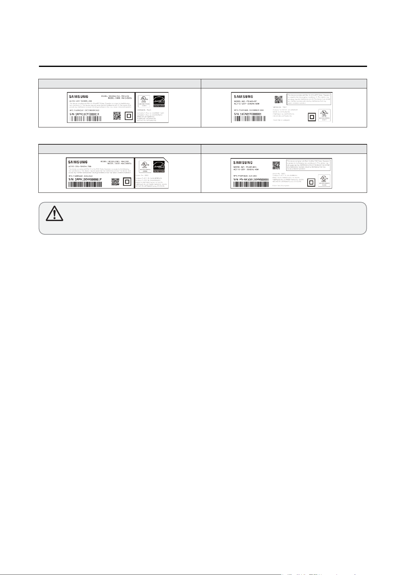
LABEL-RATING(SET)
LABEL-RATING(Subwoofer)
LABEL-RATING(SET) LABEL-RATING(Subwoofer)
GB02
TA01
• If the Version No. is “ TD04” on label, Disassemble it according to the disassembly method of the page 10~ 13.
• If the Version No. is “GC03” on label, Disassemble it according to the disassembly method of the page 14~ 15.
Caution
1-5. Proeuct Version
9
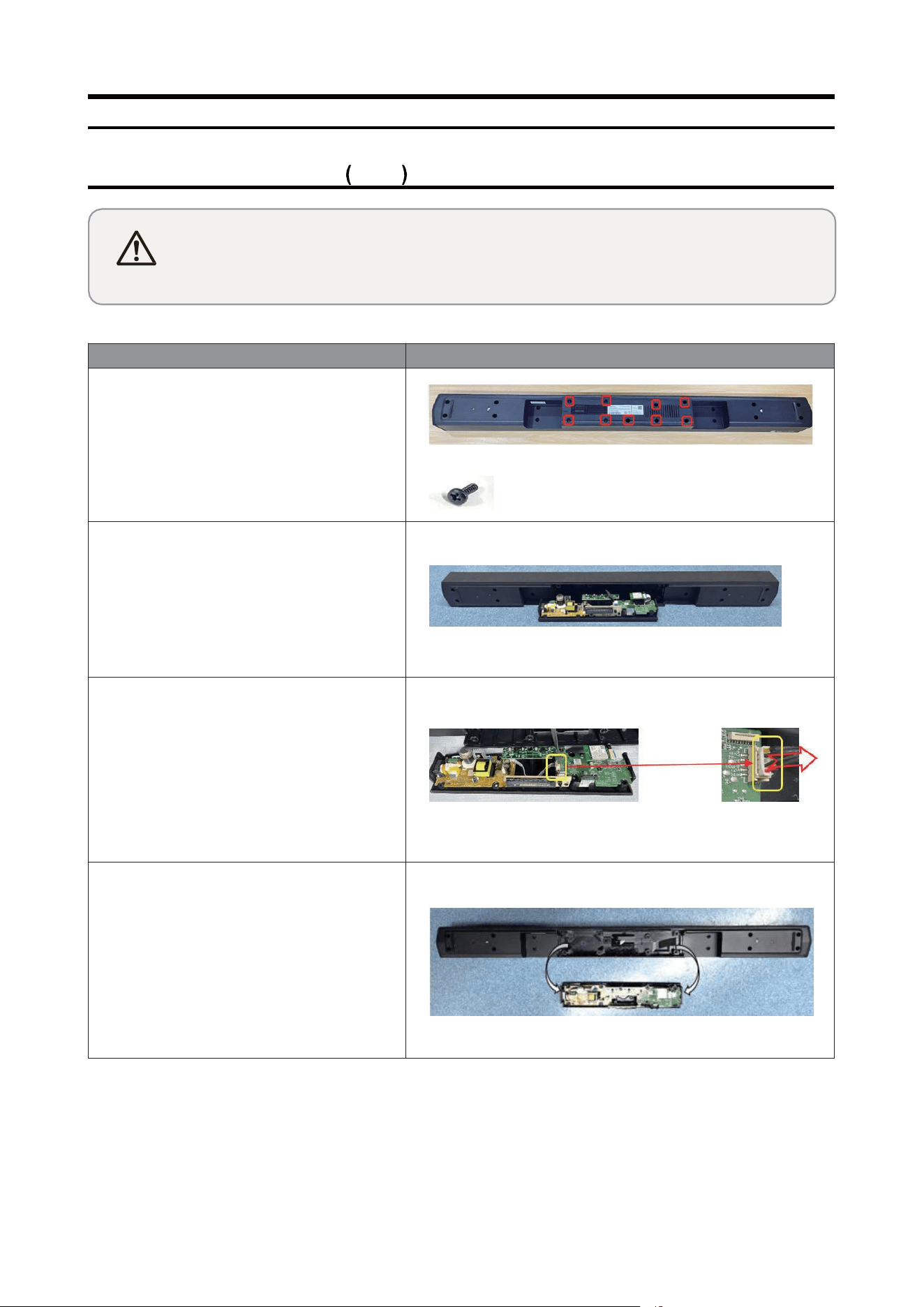
Description
Picture Description
1 Separate the PCB Assy
1
Unfasten 9 screws on the Rear Cover
SCREW PAR T CODE:AH81-12734A
1-2 Lift up the PCB Assyfrom the MAIN
BODY
1-3 Remove the cable of the PCS Assy
1-4 Separate the PCS Assy from the MAIN
BODY
Disassem bl y and Reassembly
2. Disassembly and Reassembly
2-1. Product Disassembly TA01
Caution
• Disconnect the product fromthe pow er source befor disasenmbly.
• Follow thses directions carefully; never use metal instruments to pryapart the cabinet.
• When disassembling the product, do not use any metal tools except for the provide jig.
10
Disassem bl y and Reassembly
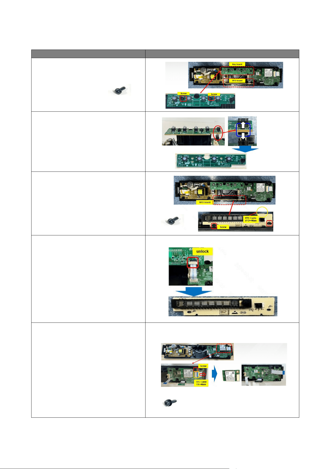
Description
Picture Description
2 Separate the Key Board and VFD
Board
1
Unfasten 2 screws
SCREW PAR T CODE :AH 81-12734A
2-2 Pull out the Pin Header vertically
2-3 Unfasten 2 screws
SCREW PAR T CODE :AH 81-12734A
2-4 Lift up the VFD board and unlock
the latch to remove the FFC cables
3 Separate Wireless Module TX &
Bluetooth Module
1
Unfasten 1 screw and remove 1 FFC.
Separate Wireless Module TX
SCREW PAR T CODE :AH 81-16804A
11
Disassem bl y and Reassembly
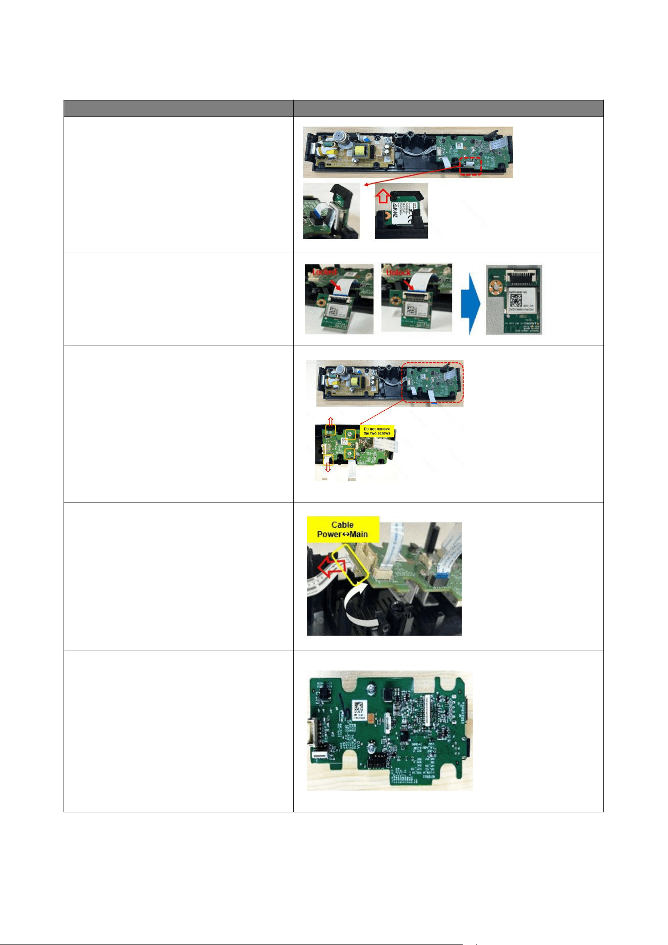
Description
Picture Description
3-2 Pull out the BT Module vertically from
the edge of main board
3-3
Open the BT Module Socket lock and
separate the FFC cable from BT Module
4 Separate the Main Board
1
Separate Mai n board from cover .
Handle the hooks of the Ma in & Power
boards with care
4-2
Lift Ma in Board up and remove Power
cable
4-3 Remove three FFC cables and
separate
the Ma in Board
12
Disassem bl y and Reassembly
2. Disassembly and Reassembly
2-2. Product Disassembly (GB02)
Caution
• Disconnect the product fromthe pow er source befor disasenmbly.
• Follow thses directions carefully; never use metal instruments to pryapart the cabinet.
• When disassembling the product, do not use any metal tools except for the provide jig.
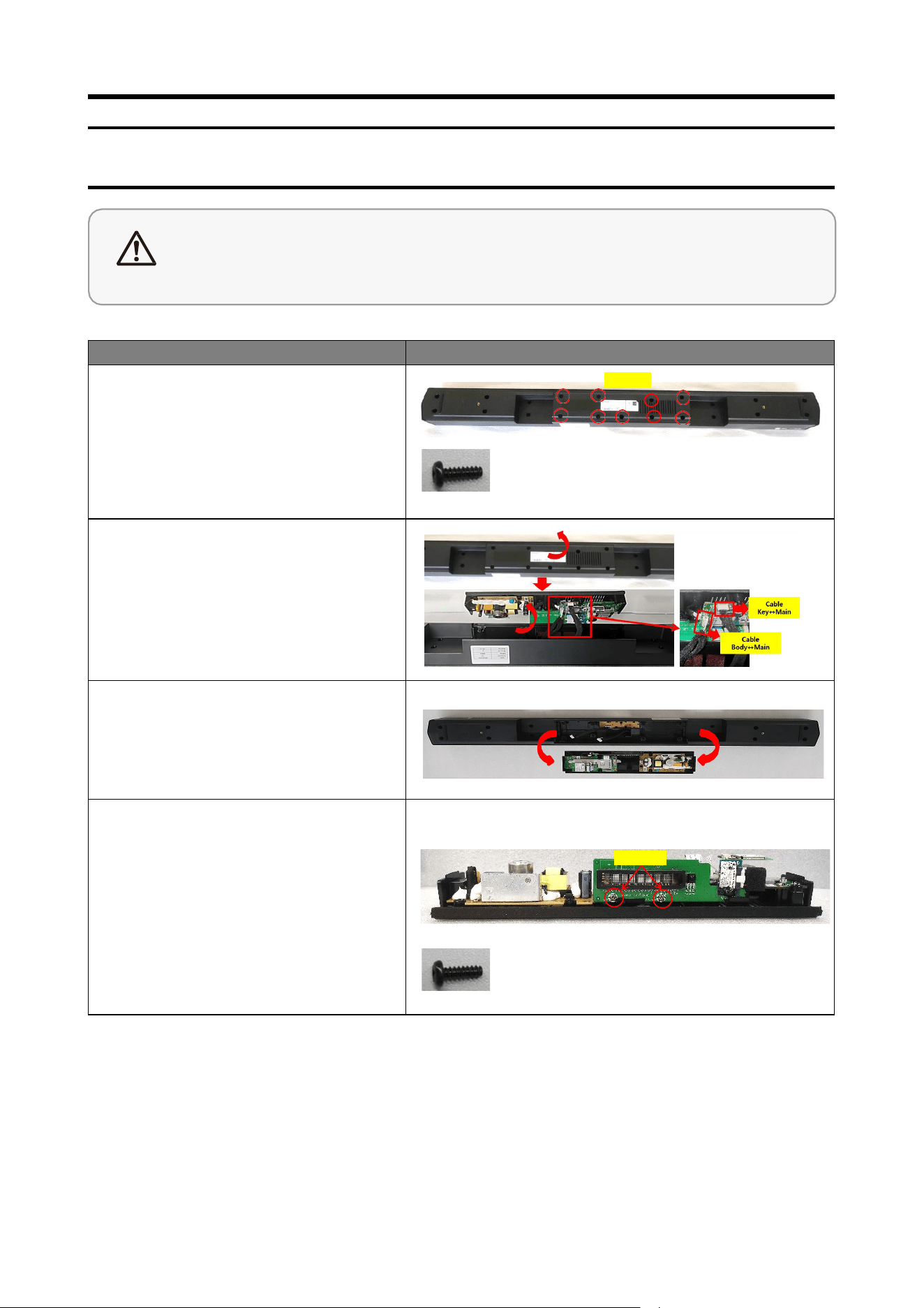
Description
Picture Descriptio
1 Separate PCB Assy
1
Unfasten 9 screws on the
COVER-SPEAKER BOTTOM.
SCREW PAR T CODE :AH 81-15940A
Screw
1-2 Lift up the C OVER -SPEAKER
BOTTOM from the MAIN -BOD Y
and remove the cable of the
PCB-MAIN .
1-3 1.3 Separate the C OVER-SPEAKER
BOTTOM from the MAIN -BOD Y.
2
Separate PCB-LED
DISPLAY / PCB-KEY
1
Unfasten 2 screws on PCB-L ED
DISPL AY.
SCREW PAR T CODE :AH 81-15941A
Screw
14
Disassem bl y and Reassembly
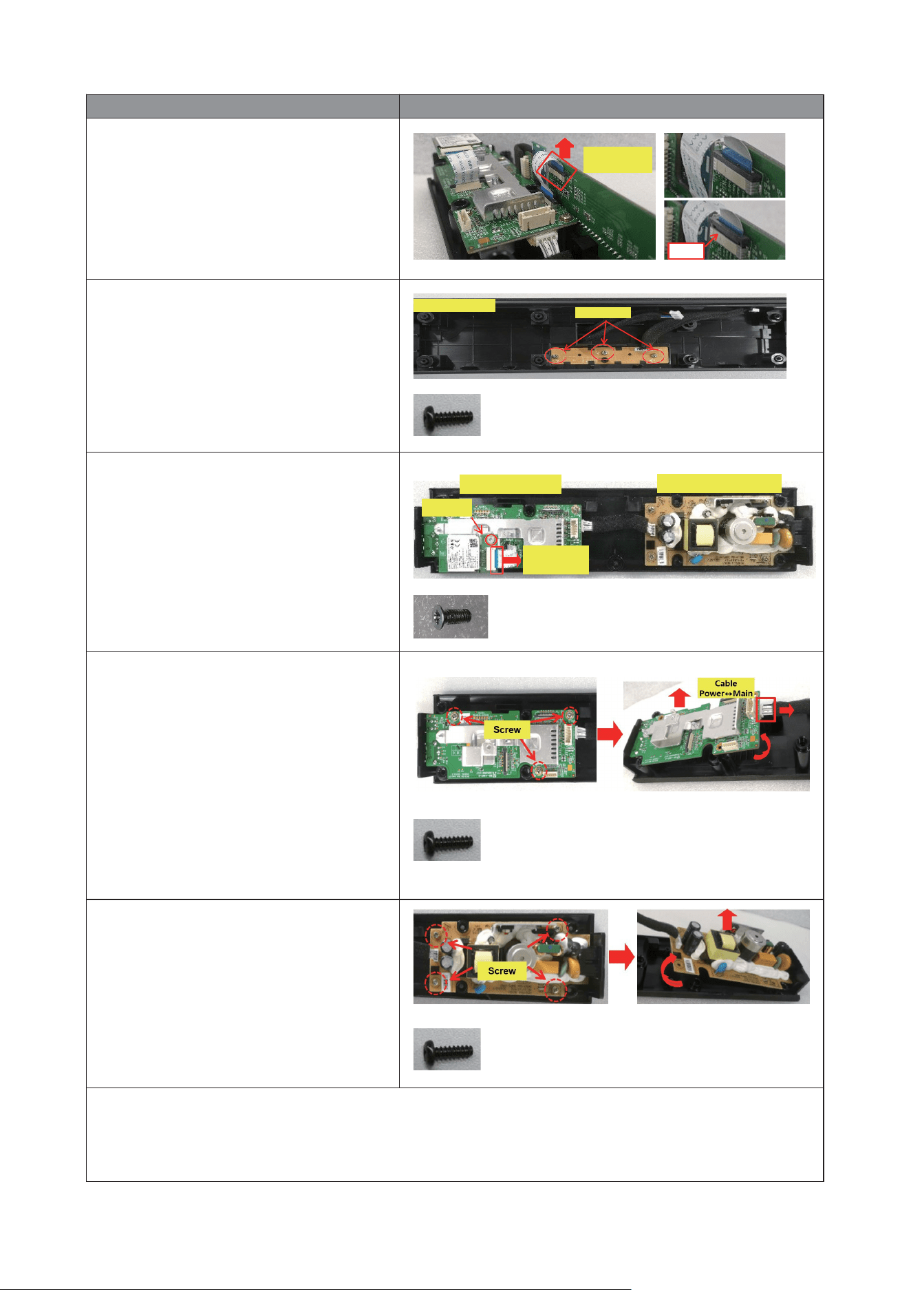
Description
Picture Description
2-2 Separate the FFC CABL E from
PCB-LED DISPLAY and separate
PCB-LED D ISPL AY.
FFC CABLE
VFD↔Mai n
PUSH
2-3 Unfasten 3 screws on PCB-KEY and
separate PCB-KEY from the
MAIN -BOD Y.
SCREW PAR T CODE :AH 81-15941A
MAIN-BO DY
Screw
3 Separate WIRELESS MODULE
TX / PCB-MAIN / ASSY-POWER
BOARD
1
Unfasten 1 screw and remove 1 FFC.
Separate Wireless Module TX.
SCREW PART CODE :: AH 81-15939A
PCB-M AIN ASSY-POW ER BOARD
Screw
FFC CABL E
TX↔Main
3-2
Unfasten 3 screws on PCB-MAIN,
lift PCB-MAIN up and remove
Power cable.
SCREW PAR T CODE :AH 81-15941A
3-3
Unfasten 4 screws on ASSY-POWER
BOARD, lift ASSY-POWER BOAR D
up and separate the ASSY-POWER
BOARD.
SCREW PAR T CODE :AH 81-15941A
4 Reassembly
Please assemble inreverse order of disassembly s teps.
15
