
Technical Support and E-Warranty Certificate
www.vevor.com/support
PASTE LIQUID FILLING MACHINE
USER MANUAL
We continue to be committed to provide you tools with competitive price.
"Save Half", "Half Price" or any other similar expressions used by us only represents an
estimate of savings you might benefit from buying certain tools with us compared to the major
top brands and does not necessarily mean to cover all categories of tools offered by us. You
are kindly reminded to verify carefully when you are placing an order with us if you are
actually saving half in comparison with the top major brands.


- 1 -
Have product questions? Need technical support? Please feel free to
contact us:
Technical Support and E-Warranty Certificate
www.vevor.com/support
NEED HELP? CONTACT US!
This is the original instruction, please read all manual instructions
carefully before operating. VEVOR reserves a clear interpretation of our
user manual. The appearance of the product shall be subject to the
product you received. Please forgive us that we won't inform you again if
there are any technology or software updates on our product.
PASTE LIQUID
FILLING MACHINE
G1WG-300, G1WG-500,
G1WG-1000, G1WG-5000
G1WY-500, G2WY-500
G2WY-1000

- 2 -
1. Read carefully and understand all ASSEMBLY AND OPERATION
INSTRUCTIONS before operating.
2. Failure to follow the safety rules and other basic safety precautions may
result in serious personal injury.
GENERAL SAFETY RULES
1. Please read the entire operating instructions before using the products
for the first time; They contain important information about the correct
operation.
2. The guarantee/warranty will be void if damage is incurred resulting from
non-compliance with the operating instructions.Liability for any and all
consequential damage is excluded! We do not assume any liability for
damage to property or personal injury caused by improper use or the
failure to observe the safety instructions! In such cases the
guarantee/warranty will be void.
3. The unauthorized conversion,modification of disassembly of the
products is inadmissible because of safety and approval reasons (CE).
4. The product is not a toy and must be kept out of the reach of
children.Particular care must therefore be exercised if children are
present.Do not leave packing materials unattended.They may become
dangerous playing material for children.
5. The product must not get damp or wet,it is only intended for use in dry,
indoor locations(not bathrooms or similarly damp areas).There is a risk of a
fatal electric shock. Do not expose the product or its accessories to damp
or extremely high or low temperatures.
6. Dropping,falling,pressure or tensile forces could destroy or at least limit
the function of the product.

- 3 -
7. Never position the device in the vicinity of combustible or easily
inflammable materials.
8. Pull the plug out before maintenance machine in case of electric shock.
9. Keep the cleanest state of the filling part, machine should be wiped by
timing, clean the pump, then using and maintain the filling machine
according the operation manual.
10. The second half of the machine (near the control button) and the lower
part of the rack with electrical control components, no matter under what
conditions can not be directly washed body with water, otherwise there will
be risk of electric shake, damage to electrical control components.
11. Please do not close to the filling head when working, pay attention to
safety!
12. Please do not put your hand on cylinder when working, pay attention to
you hand!
SAVE THESE INSTRUCTIONS

- 4 -
MODEL AND PARAMETERS
Model
G1WG-300
G1WG-500
G1WG-1000
G1WG-5000
Filling
range
30-300ml
50-500ml
100-1000ml
500-5000ml
Voltage
AC 120V 60Hz
Power
10W
10W
10W
10W
Air
pressure
0.4-0.6MPA
Filling
speed
10-30 bottles/min
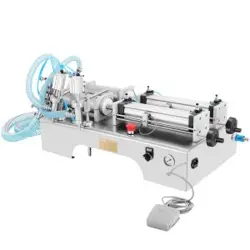
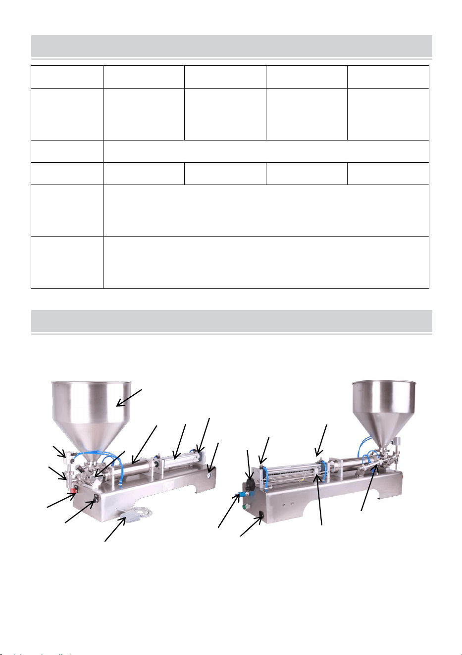
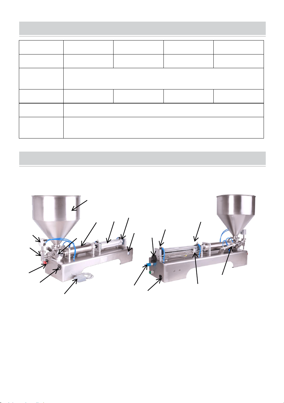
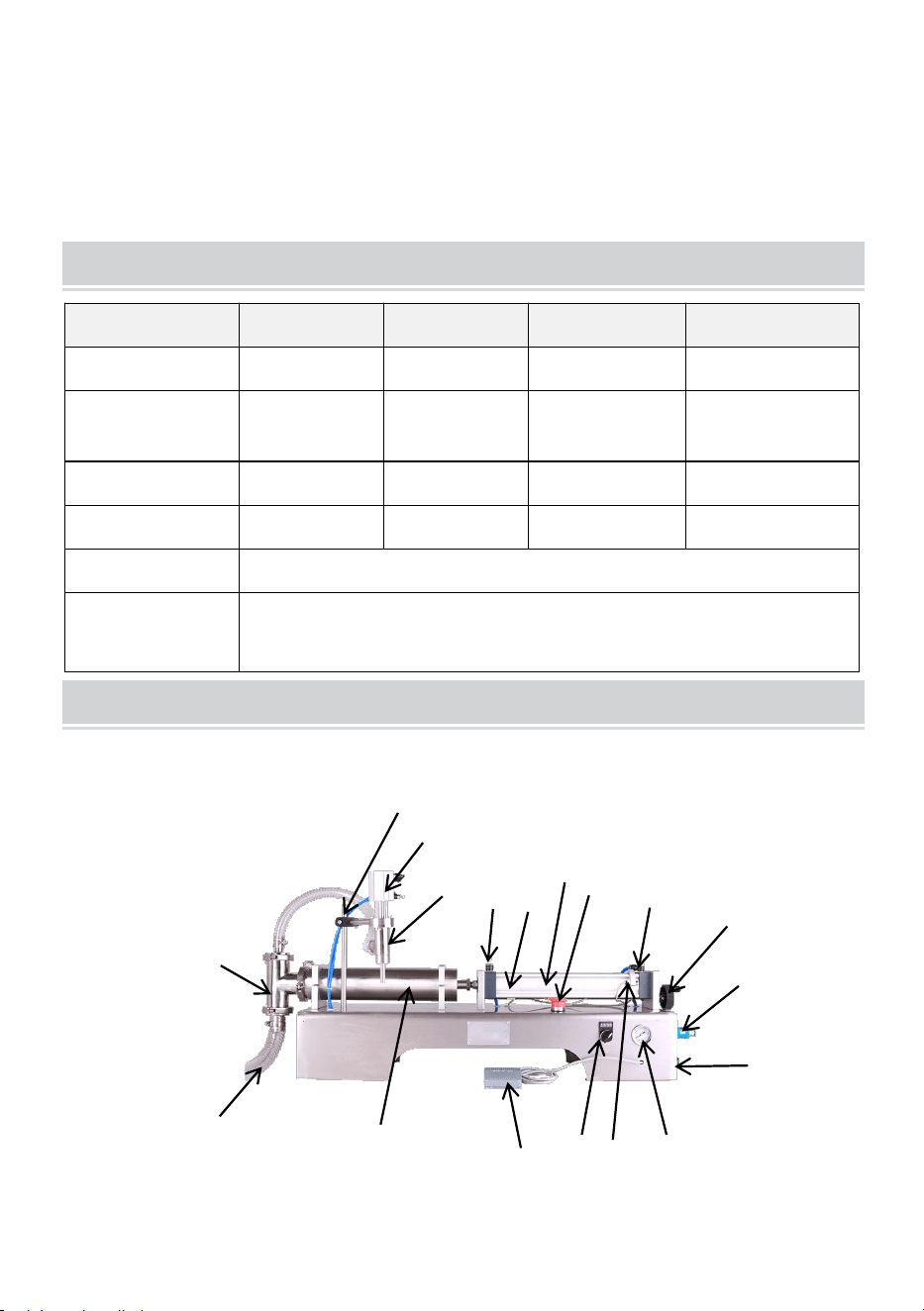
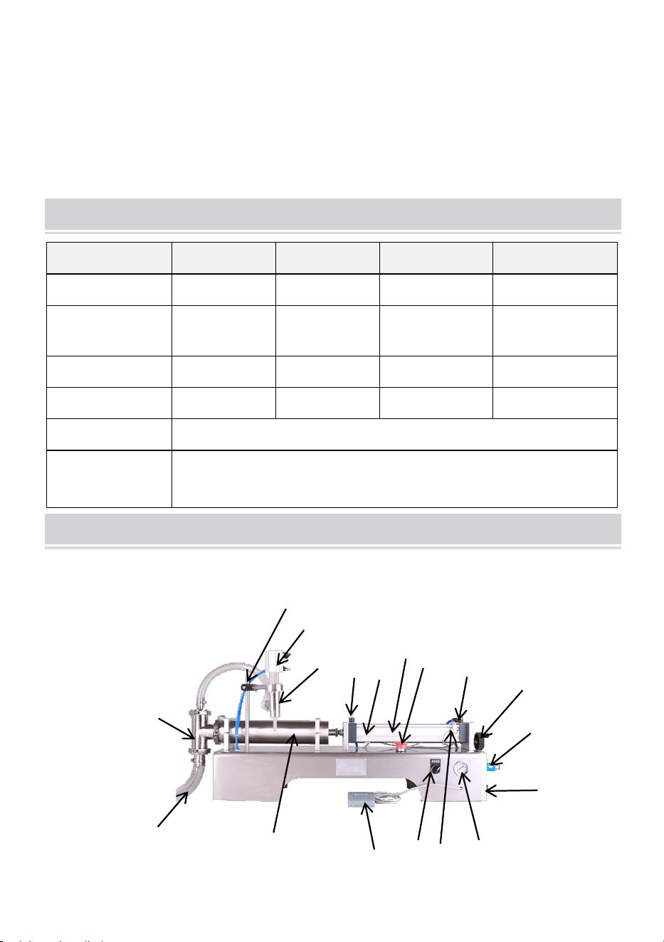
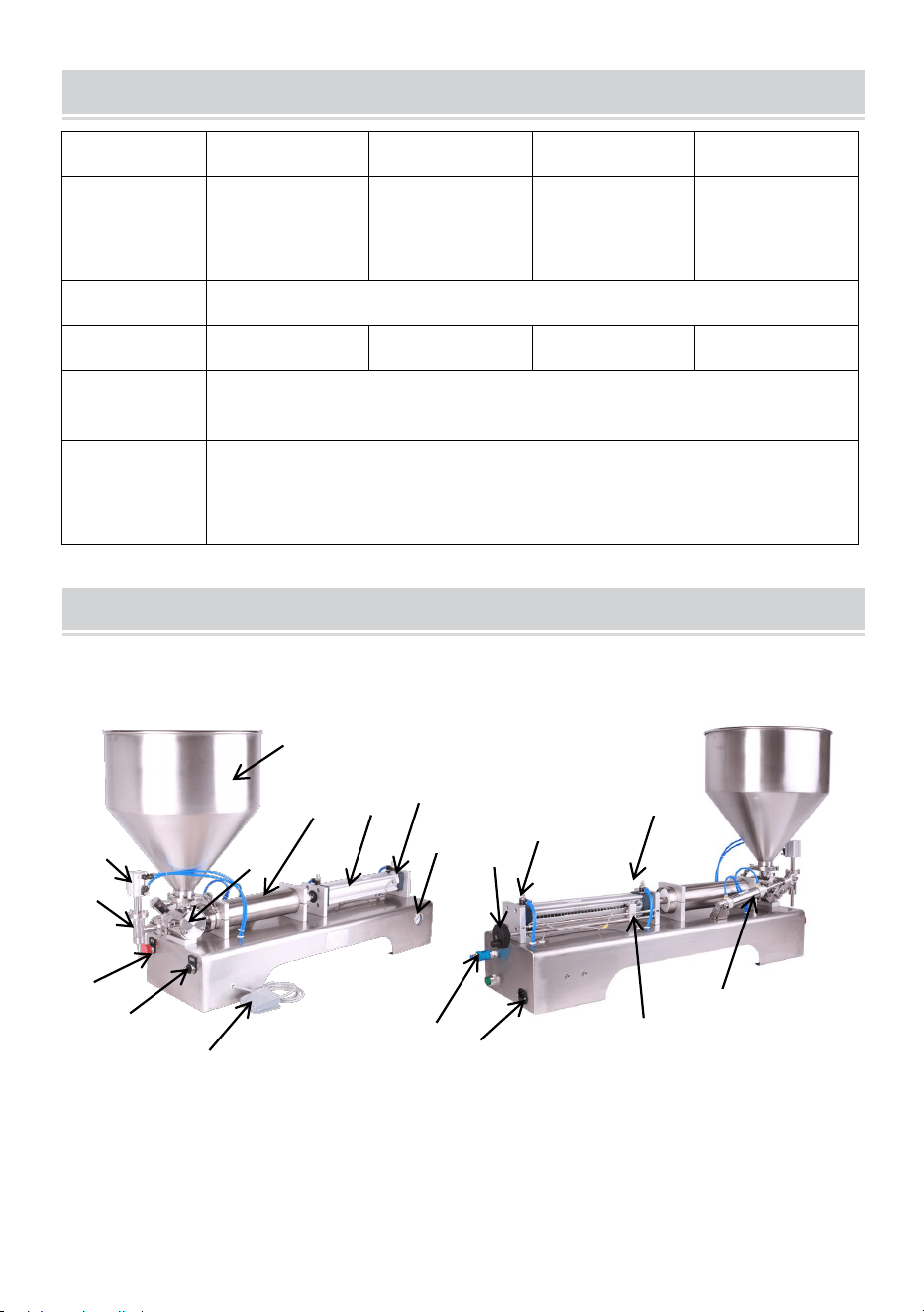
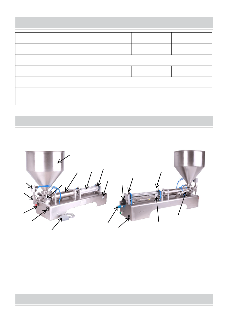
STRUCTURE DIAGRAM
G1WG-300, G1WG-500, G1WG-1000, G1WG-5000
1. Hopper 2. Rotary valve 3. Filling head 4.Cylinder for filling head
5.Emergency stop 6. Jogging and automatic modes 7. Foot switch
8.Cylinder barrel 9. Primary air cylinder 10. Pneumatic valve
11.Power plug 12.The cylinder that controls the rotary valve
13.Throttle valve NO.1 14.Throttle valve NO.2 15.magnetic switch NO.1
16.Hand joystick 17.Barometer 18.magnetic switch NO.2
1
4
2
3
6
7
8
9
10
5
11
12
13
14
17
16
15
18
- 5 -
MODEL AND PARAMETERS
Model
G1WY-500
G2WY-500
G2WY-1000
G2WY-1000
Filling range
50-500ml
50-500ml
100-1000ml
100-1000ml
Voltage
AC 120V
60Hz
AC 120V
60Hz
AC 120V
60Hz
AC 230V
50Hz
Power
10W
20W
20W
20W
Number of
Head
Single
Double
Double
Double
Air pressure
0.4-0.6MPA
Filling speed
Single head: 10-30 bottles/min
double heads: 20-60bottles/min
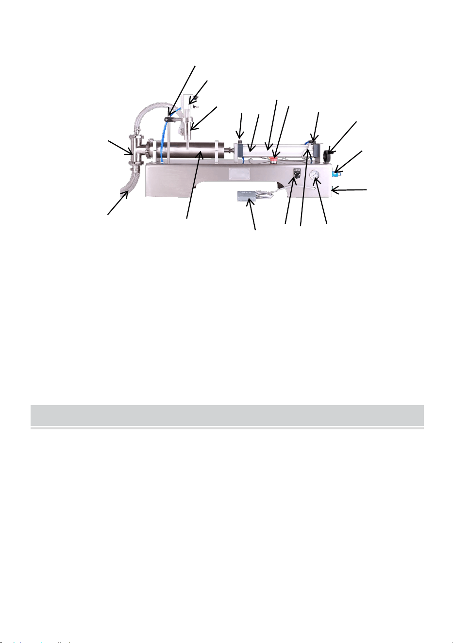
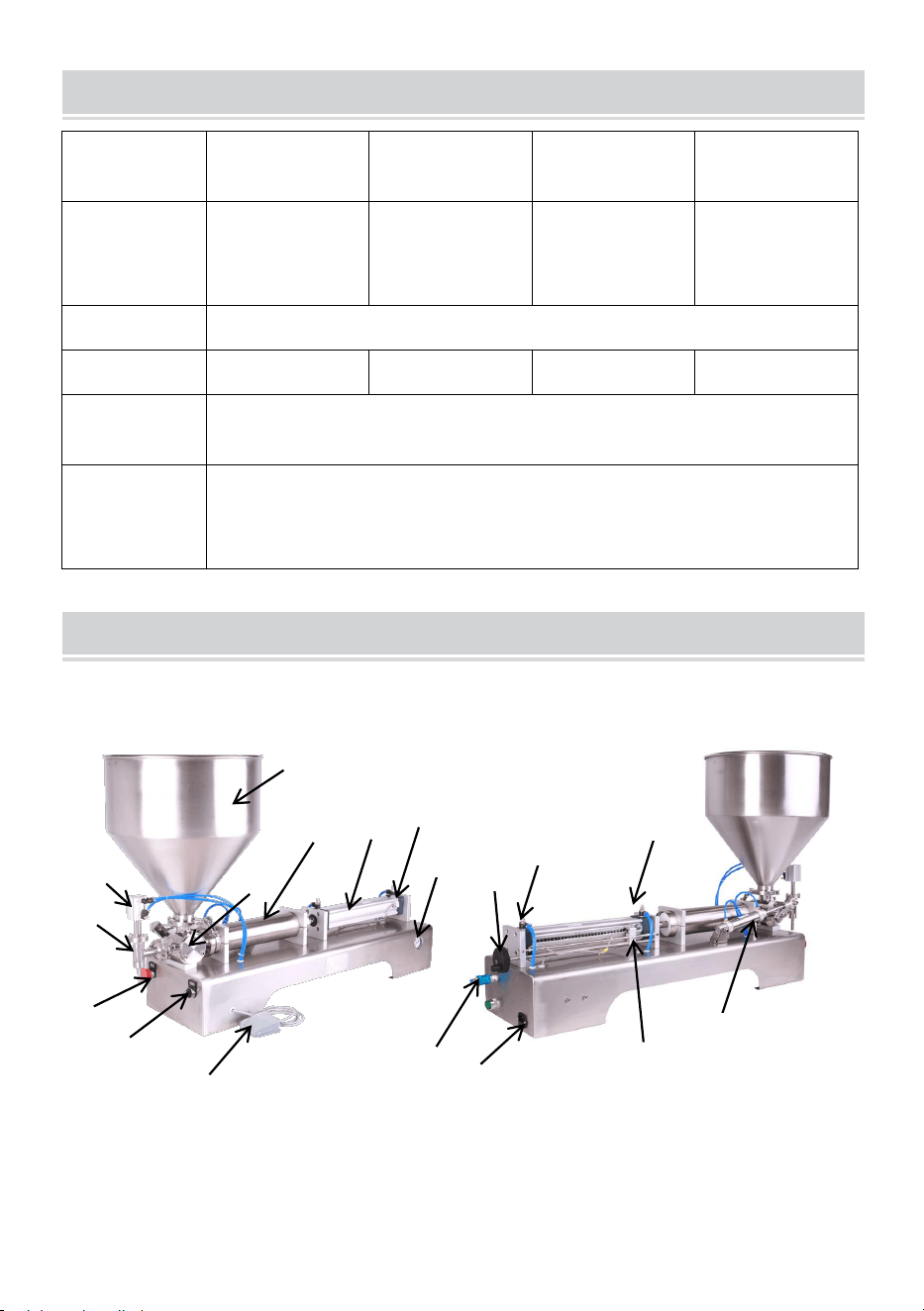
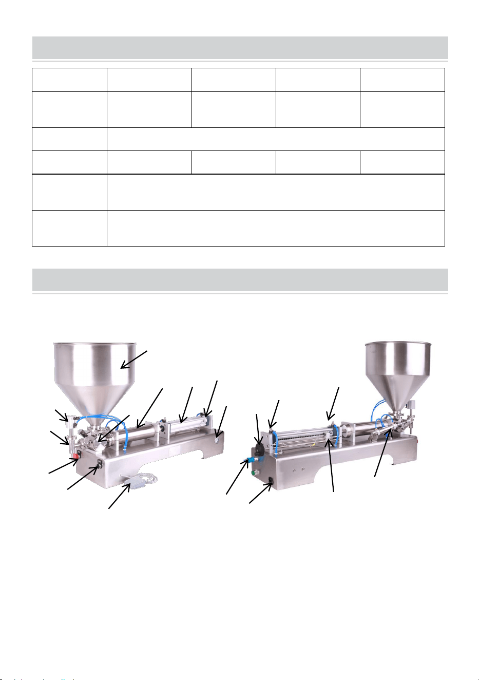
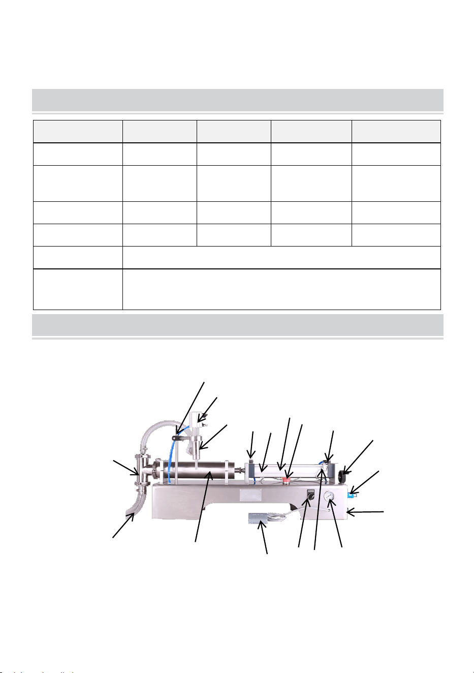
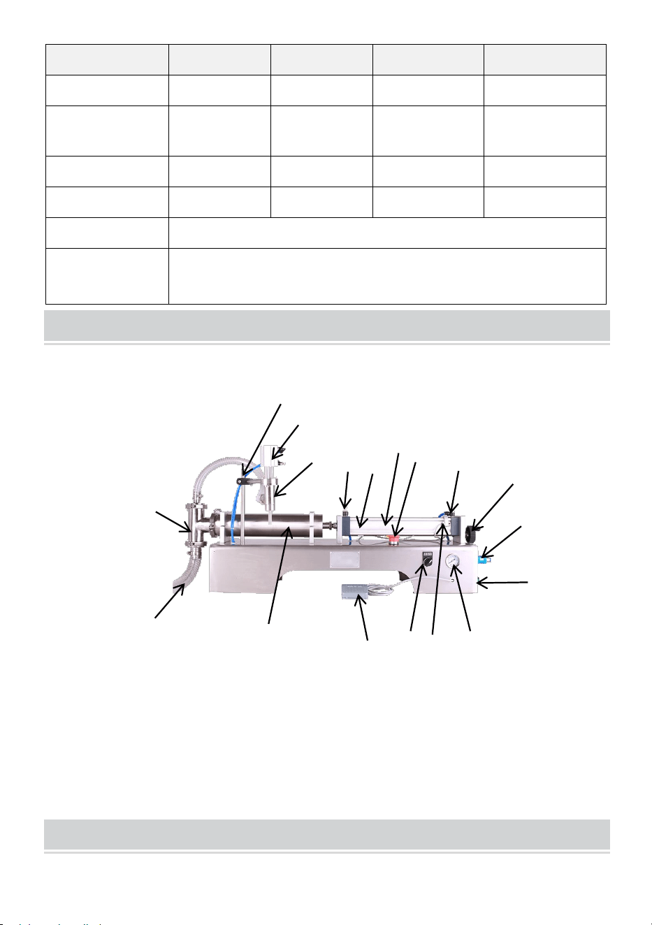
STRUCTURE DIAGRAM
1.Feed pipe 2.three-way valve 3.Filling head 4.Cylinder for filling head
5.Emergency stop 6. Jogging and automatic modes 7. Foot switch
8.Cylinder barrel 9. Primary air cylinder 10. Pneumatic valve
11.Power plug 12.support 13.Throttle valve NO.1
14.Throttle valve NO.2 15.magnetic switch NO.1
16.Hand joystick 17.Barometer 18.magnetic switch NO.2
2
5
1
15
10
8
12
3
14
11
16
9
13
17
4
6
7
18
G1WY-500, G2WY-500, G2WY-1000
- 6 -
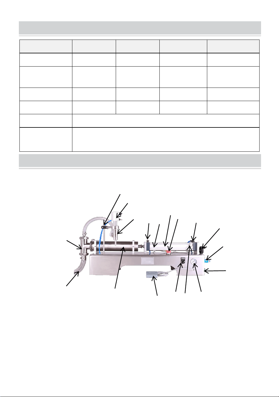
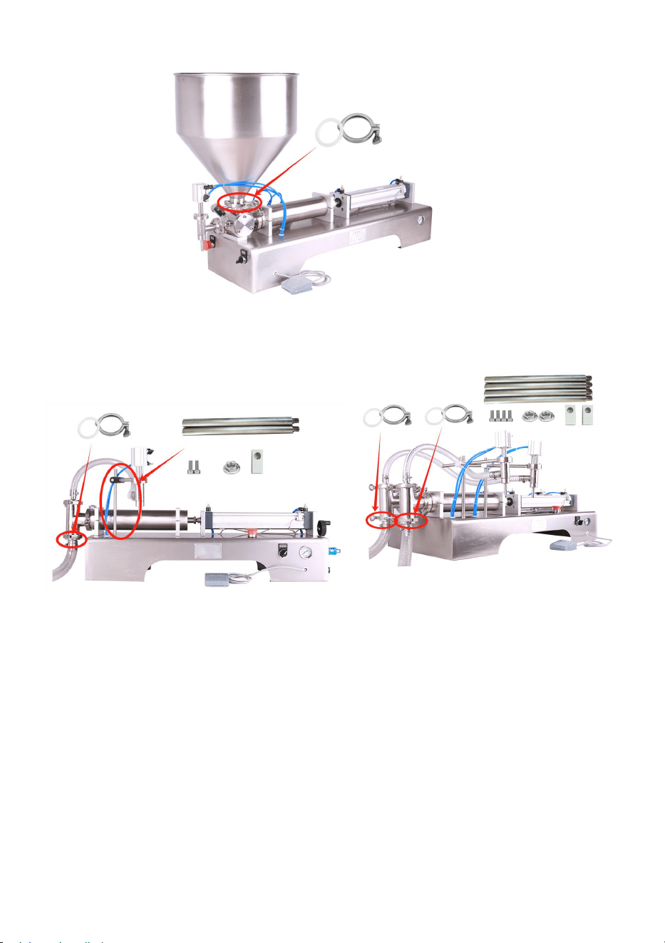
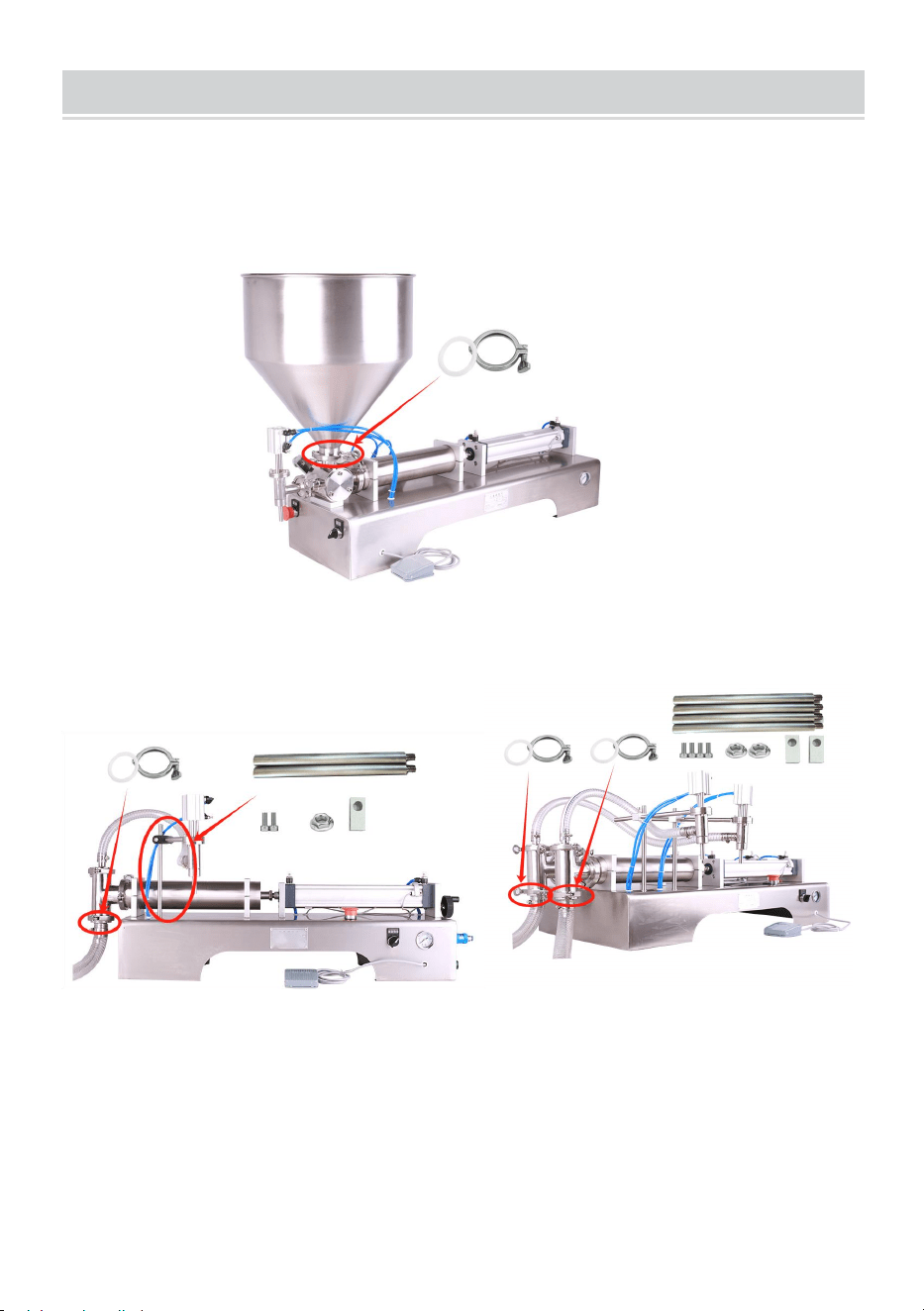
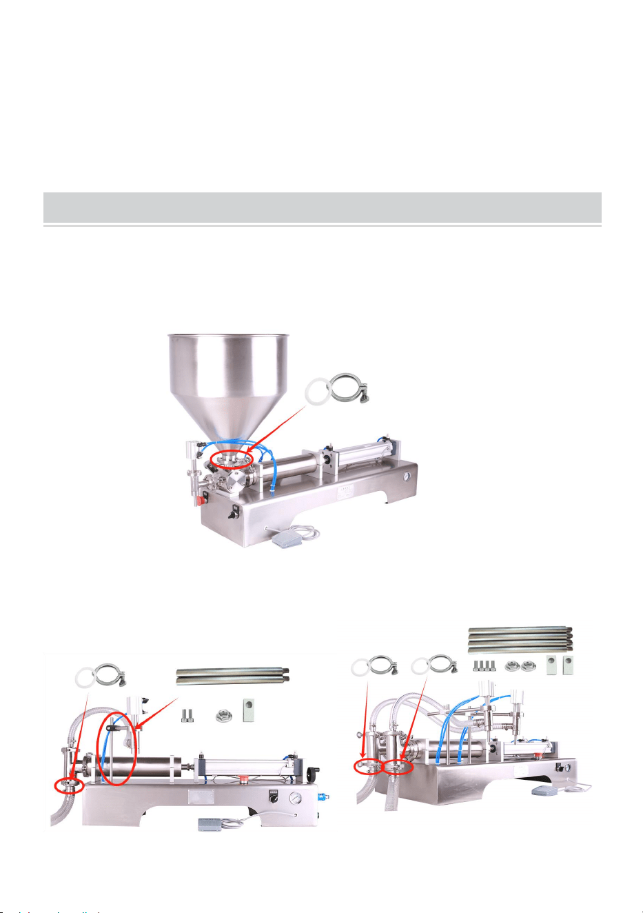
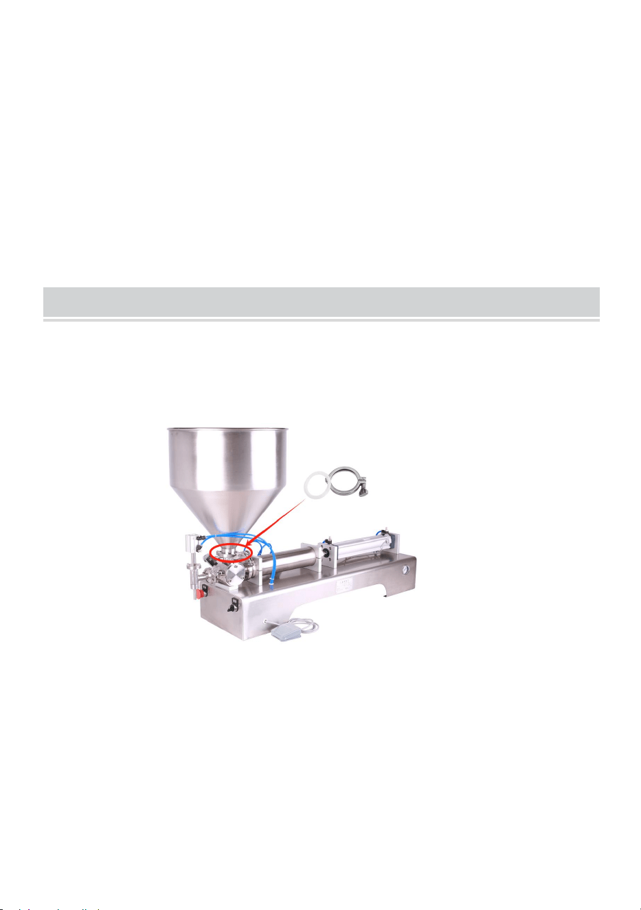
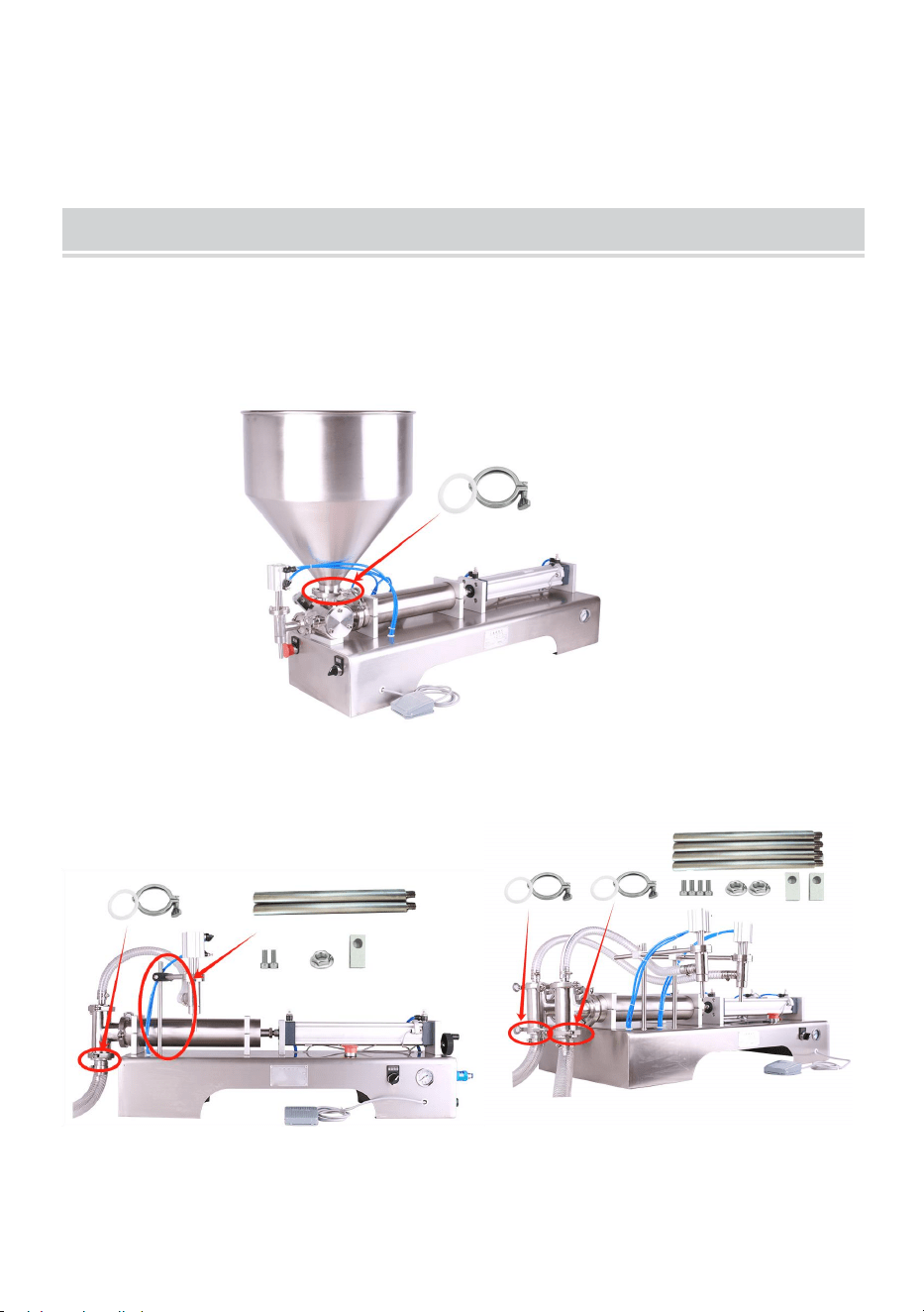
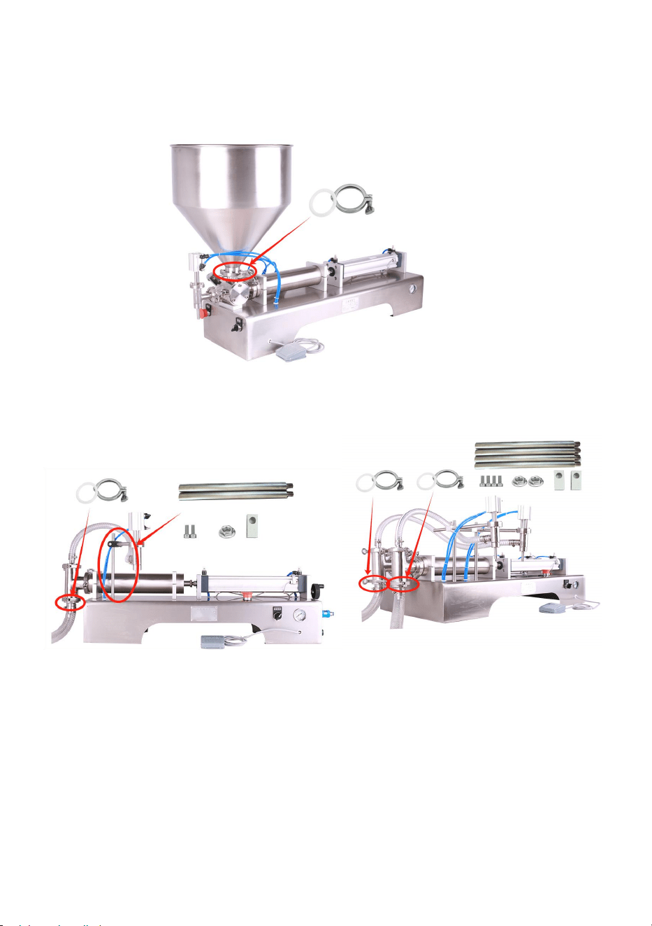
OPERATING INSTRUCTIONS
Step1:
1) G1WG-300,G1WG-500,G1WG-1000,G1WG-5000
Installing and fixing the hopper.
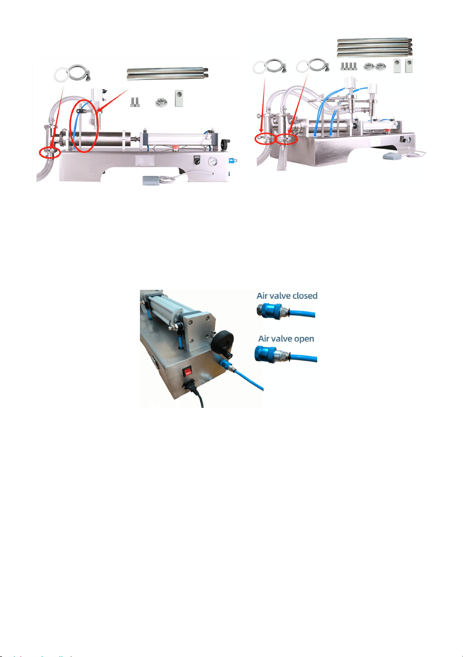
2) G1WY-500,G2WY-500,G2WY-1000
Connect the feed pipe and fixed filling head:
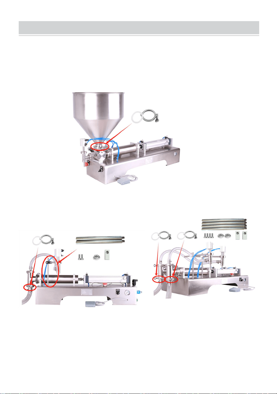
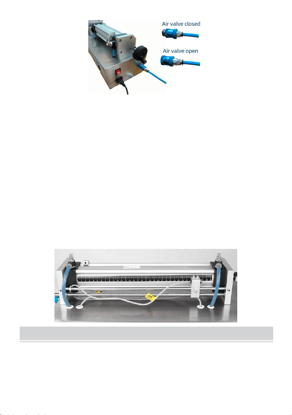
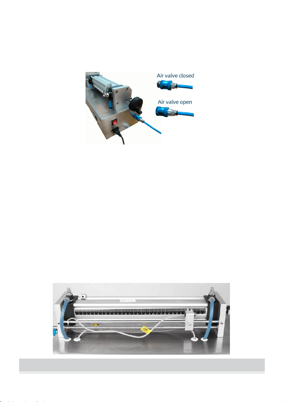
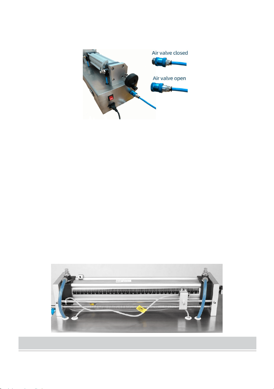
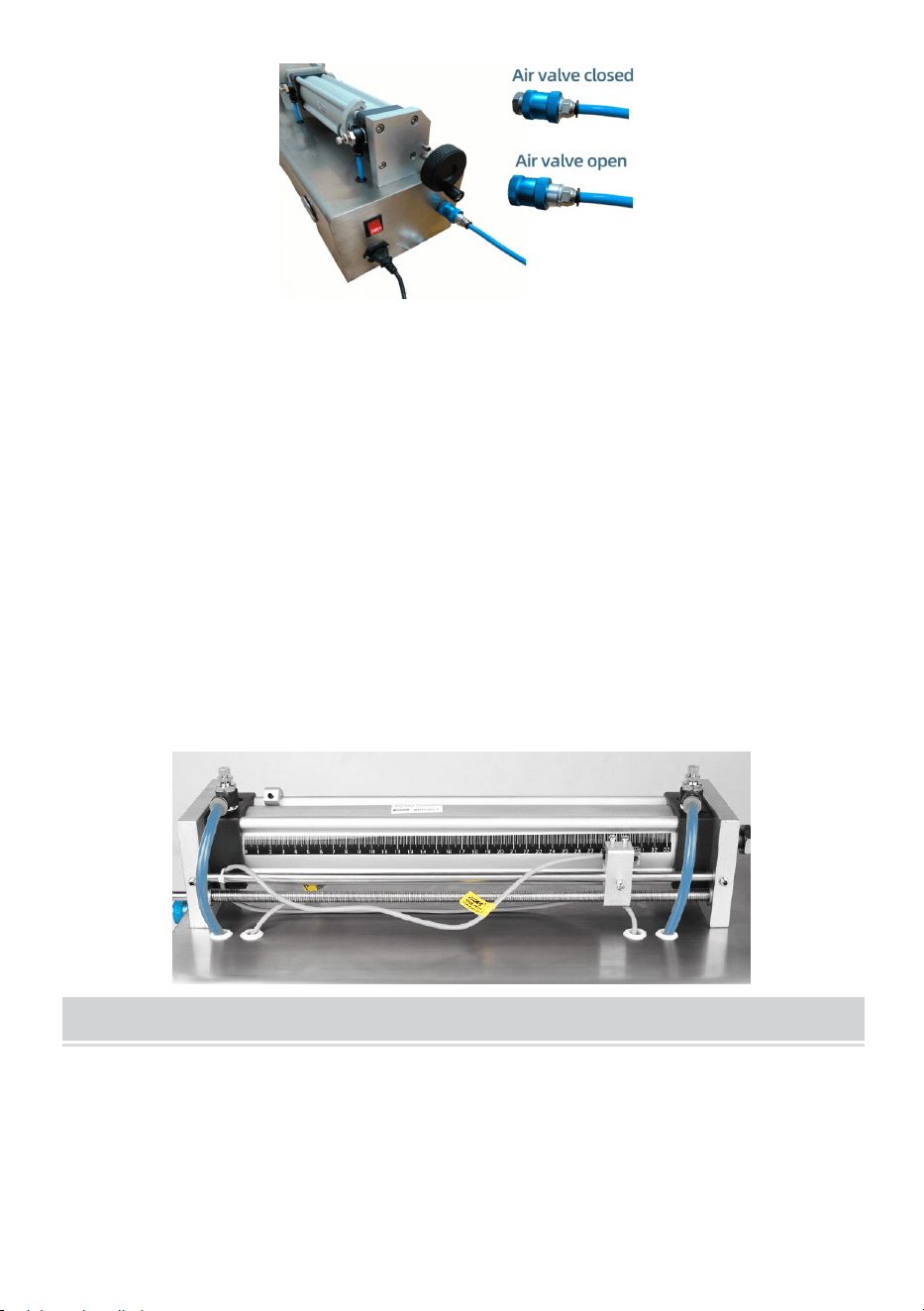
Step2:Connect the power supply and pay attention to the voltage.Connect
the air compressor and insert the air pipe into the pneumatic valve.When
pushing the slider inward, the machine is connected to the air source; Pull
the slider outward and disconnect the air supply from the machine.
- 7 -
Step3:Adjusting filling volume and filling speed. When turning the joystick
counterclockwise, the magnetic switch(NO.1) will move forward, increasing
the filling amount. When turning the joystick clockwise, the magnetic
switch(NO.1) will move backwards, reducing the filling amount. Note that
when adjusting, the position of the magnetic switch(NO.1) should not be
too forward or too backward, as it cannot function beyond the filling range
of the machine. Turning the throttle valve(NO.2) clockwise will slow down
the speed of the cylinder pushing out, that is, the discharge speed will slow
down. The opposite is also true. Turning the throttle valve(NO.1)
clockwise will slow down the cylinder's retraction speed. The opposite is
also true.
MAINTENANCE
1. After using , the surface of the machine should be cleaned and residual
materials inside the machine should be removed. Do not put your fingers
into the rotary valve during cleaning.
2. When storing, keep in a clean, dry, and safe location away from
children.
3. All maintenance, service, and repairs not discussed in the manual

- 8 -
should only be performed by qualified service technicians.
TROUBLESHOOTING
Problem
Possible Cause
Possible Solution
Air cylinder does not
work
The air compressor
is not turned on
Open the valve of the air
compressor
The pneumatic valve
is not open
Push the pneumatic valve(10)
inward
Emergency stop
switch not released
Release the emergency stop
switch
The position of the
magnetic
switch(NO.2) is
loose
Move the magnetic switch(NO.2)
left and right until the machine can
start, then re secure the magnetic
switch
The throttle
valve(NO.2) has
been tightened
Turn the throttle valve(NO.2)
counterclockwise
The cylinder is
blocked
Clean the inside of the cylinder
barrel
The cylinder that
controls the rotary
valve does not
move
Wear of the valve
core of the rotary
valve
Take out the valve core for
polishing
The filling head
cannot produce
materials
The filling head is
blocked inside
Disassemble and clean the filling
head
The filling head
cylinder is broken
Replacing the cylinder
When the cylinder is
pushed to the front,
it cannot come back
The magnetic switch
is broken
Replace the magnetic
switch(NO.1)
The position of the
magnetic switch is
incorrect
Move the magnetic switch(NO.1)
backwards

- 9 -
Address: Baoshanqu Shuangchenglu 803long 11hao 1602A-1609shi
Shanghai
Imported to AUS: SIHAO PTY LTD. 1 ROKEVA STREETEASTWOOD
NSW 2122 Australia
Imported to USA: Sanven Technology Ltd. Suite 250. 9166 Anaheim
Place, Rancho Cucamonga, CA 91730
REP
EC
SHUNSHUN GmbH
Römeräcker 9 Z2021, 76351
Linkenheim-Hochstetten, Germany
REP
UK
Pooledas Group Ltd
Unit 5 Albert Edward House, The
Pavilions Preston, United Kingdom
Made In China


Assistance technique et certificat de garantie électronique
www.vevor.com/support
MACHINE DE REMPLISSAGE DE LIQUIDE EN
PÂTE
MANUEL D'UTILISATION
We continue to be committed to provide you tools with competitive price.
"Save Half", "Half Price" or any other similar expressions used by us only represents an
estimate of savings you might benefit from buying certain tools with us compared to the major
top brands and does not necessarily mean to cover all categories of tools offered by us. You
are kindly reminded to verify carefully when you are placing an order with us if you are
actually saving half in comparison with the top major brands.


- 1 -
Have product questions? Need technical support? Please feel free to
contact us:
Technical Support and E-Warranty Certificate
www.vevor.com/support
NEED HELP? CONTACT US!
This is the original instruction, please read all manual instructions
carefully before operating. VEVOR reserves a clear interpretation of our
user manual. The appearance of the product shall be subject to the
product you received. Please forgive us that we won't inform you again if
there are any technology or software updates on our product.
PASTE LIQUID
FILLING MACHINE
G1WG-300, G1WG-500,
G1WG-1000, G1WG-5000
G1WY-500, G2WY-500
G2WY-1000

- 2 -
3. Lisez attentivement et comprenez toutes les INSTRUCTIONS
D'ASSEMBLAGE ET D'UTILISATION avant d'utiliser l'appareil.
4. Le non-respect des règles de sécurité et des autres précautions de
sécurité de base peut entraîner des blessures corporelles graves.
GENERAL SAFETY RULES
13. Veuillez lire l'intégralité du mode d' emploi avant d' utiliser les produits
pour la première fois ; il contient des informations importantes sur le bon
fonctionnement .
14. La garantie est annulée en cas de dommages résultant du non -
respect des instructions d' utilisation. Nous déclinons toute responsabilité
pour les dommages consécutifs ! Nous déclinons toute responsabilité pour
les dommages matériels ou corporels résultant d'une utilisation
inappropriée ou du non-respect des consignes de sécurité ! Dans de tels
cas, la garantie sera annulée .
15. La transformation, la modification ou le démontage non autorisé des
produits est inadmissible pour des raisons de sécurité et d'homologation
( CE).
16. Le produit n'est pas un jouet et doit être conservé hors de portée des
enfants . Il convient donc de faire particulièrement attention en présence
d'enfants . Ne laissez pas les matériaux d'emballage sans surveillance . Ils
peuvent devenir un jouet dangereux pour les enfants.
17. Le produit ne doit pas être mouillé ou exposé à l'humidité. Il est
uniquement destiné à être utilisé dans des endroits secs et intérieurs (pas
dans des salles de bains ou des zones humides similaires). Il existe un
risque de décharge électrique mortelle. N'exposez pas le produit ou ses
accessoires à l'humidité ou à des températures extrêmement élevées ou
basses.

- 3 -
18. Une chute, une pression ou des forces de traction pourraient détruire
ou au moins limiter la fonction du produit.
19. placez jamais l'appareil à proximité de combustibles ou de matériaux
facilement inflammables. matériaux inflammables .
20. Débranchez la machine avant de procéder à l'entretien en cas de choc
électrique.
21. Maintenez l'état le plus propre possible de la partie de remplissage, la
machine doit être essuyée au bon moment, nettoyez la pompe, puis
utilisez et entretenez la machine de remplissage conformément au manuel
d'utilisation .
22. La deuxième moitié de la machine (près du bouton de commande) et
la partie inférieure du rack avec des composants de commande électriques,
quelles que soient les conditions, ils ne peuvent pas être directement corps
lavé avec de l'eau, sinon il y aura un risque de secousse électrique, de
dommages aux appareils électriques composants de contrôle.
23. Veuillez ne pas vous approcher de la tête de remplissage lorsque vous
travaillez, faites attention à la sécurité !
24. Veuillez ne pas mettre votre main sur le cylindre lorsque vous
travaillez, faites attention à votre main !
CONSERVEZ CES INSTRUCTIONS
- 4 -
MODEL AND PARAMETERS
Modèle
G1WG-300
G1WG-500
G1WG-1000
G1WG-5000
Plage de
remplissag
e
30-300 ml
50-500 ml
100-1000 ml
500-5000 ml
Tension
CA 120 V 60 Hz
Pouvoir
10 W
10 W
10 W
10 W
Pression
atmosphéri
que
0,4-0,6 MPA
Vitesse de
remplissag
e
10-30 bouteilles/min
STRUCTURE DIAGRAM
G1WG-300, G1WG-500, G1WG-1000, G1WG-5000
2. Trémie 2. Vanne rotative 3. Tête de remplissage 4. Cylindre
pour tête de remplissage 5. Arrêt d'urgence 6. Modes jogging et
automatique 7. Interrupteur à pédale 8. Barillet du cylindre 9. Cylindre
1
4
2
3
6
7
8
9
10
5
11
12
13
14
17
16
15
18

- 5 -
d' air primaire 10. Vanne pneumatique
12.Fiche d'alimentation 12. Le cylindre qui contrôle la vanne rotative
13. Vanne papillon N°1 14. Vanne papillon N°2 15. Interrupteur
magnétique N°1
16. Joystick manuel 17. Baromètre 18. Interrupteur magnétique N°2
MODEL AND PARAMETERS
Modèle
G1WY-500
G2WY-500
G2WY-1000
G2WY-1000
Plage de
remplissage
50-500 ml
50-500 ml
100-1000 ml
100-1000 ml
Tension
CA 120 V
60 Hz
CA 120 V
60 Hz
CA 120 V 60
Hz
CA 230 V 50
Hz
Pouvoir
10 W
20 W
20 W
20 W
Nombre de
têtes
Célibataire
Double
Double
Double
Pression
atmosphériqu
0,4-0,6 MPA
Vitesse de
remplissage
Tête unique : 10-30 bouteilles/min
têtes doubles : 20-60 bouteilles/min
STRUCTURE DIAGRAM
- 6 -
1.Tuyau d'alimentation 2. vanne à trois voies 3. Tête de remplissage 4.
Cylindre pour tête de remplissage 5. Arrêt d'urgence 6. Modes jogging
et automatique 7. Interrupteur à pédale 8. Barillet du cylindre 9.
Cylindre d' air primaire 10. Vanne pneumatique
11.Fiche d'alimentation 12.Support 13.Vanne d'accélérateur NO.1
14. Vanne papillon N°2 15. Interrupteur magnétique N°1
16. Joystick manuel 17. Baromètre 18. Interrupteur magnétique N°2
OPERATING INSTRUCTIONS
Étape 1 :
3) G1WG-300,G1WG-500,G1WG-1000,G1WG-5000
Installation et fixation de la trémie .
2
5
1
15
10
8
12
3
14
11
16
9
13
17
4
6
7
18
G1WY-500, G2WY-500, G2WY-1000
- 7 -
4) G1WY-500, G2WY-500, G2WY-1000
Raccorder le tuyau d'alimentation et la tête de remplissage fixe :
Étape 2 : Connectez l'alimentation électrique et faites attention à la
tension . Connectez le compresseur d'air et insérez le tuyau d'air dans la
vanne pneumatique. Lorsque vous poussez le curseur vers l'intérieur, la
machine est connectée à la source d'air ; tirez le curseur vers l'extérieur et
déconnectez l'alimentation en air de la machine.
- 8 -
Étape 3 : Réglage du volume de remplissage et de la vitesse de
remplissage. Lorsque vous tournez le joystick dans le sens inverse des
aiguilles d'une montre, l'interrupteur magnétique ( NO.1) se déplace vers
l'avant, augmentant la quantité de remplissage. Lorsque vous tournez le
joystick dans le sens des aiguilles d'une montre, l'interrupteur magnétique
(NO.1 ) se déplace vers l'arrière, réduisant la quantité de remplissage.
Notez que lors du réglage, la position de l'interrupteur magnétique (NO.1)
ne doit pas être trop en avant ou trop en arrière, car il ne peut pas
fonctionner au-delà de la plage de remplissage de la machine. Tourner le
papillon des gaz (NO.2) dans le sens des aiguilles d'une montre ralentira la
vitesse de poussée du vérin, c'est-à-dire que la vitesse de décharge
ralentira. L'inverse est également vrai. Tourner le papillon des gaz (NO.1)
dans le sens des aiguilles d'une montre ralentira la vitesse de rétraction du
vérin. L'inverse est également vrai.
MAINTENANCE
4. Après utilisation , la surface de la machine doit être nettoyée et les
résidus de matériaux à l'intérieur de la machine doivent être éliminés. Ne
mettez pas vos doigts dans la vanne rotative pendant le nettoyage .
5. Lors du stockage, conserver dans un endroit propre, sec et sûr, hors de

- 9 -
portée des enfants.
6. Tous les travaux d'entretien, de réparation et de maintenance non
décrits dans le manuel doivent être effectués uniquement par des
techniciens de maintenance qualifiés .
TROUBLESHOOTING
Problème
Cause possible
Solution possible
Le cylindre à air ne
fonctionne pas travail
Le compresseur
d'air n'est pas
allumé
Ouvrir la vanne du compresseur
d'air
La vanne
pneumatique n'est
pas ouverte
Poussez la valve pneumatique
(10) vers l'intérieur
Interrupteur d'arrêt
d'urgence non
relâché
Relâchez l'interrupteur d'arrêt
d'urgence
La position de
l'interrupteur
magnétique (NO.2)
est lâche
Déplacez l'interrupteur
magnétique (n° 2) vers la
gauche et la droite jusqu'à ce que
la machine puisse démarrer, puis
revissez l'interrupteur magnétique
Le papillon des gaz
(n°2) a été
resserré
Tournez le papillon des gaz (n°
2) dans le sens inverse des
aiguilles d'une montre
Le cylindre est
bloqué
Nettoyer l'intérieur du barillet du
cylindre
Le cylindre qui
contrôle la vanne
rotative ne bouge pas
Usure du noyau de
la soupape rotative
Retirez le noyau de la valve pour
le polir
La tête de
remplissage ne peut
La tête de
remplissage est
Démonter et nettoyer la tête de
remplissage

- 10 -
pas produire de
matériaux
bloquée à l'intérieur
Le cylindre de la
tête de remplissage
est cassé
Remplacement du cylindre
Lorsque le cylindre
est poussé vers
l'avant, il ne peut pas
revenir en arrière
L'interrupteur
magnétique est
cassé
Remplacer l'interrupteur
magnétique (NO.1)
La position de
l'interrupteur
magnétique est
incorrecte
Déplacez l'interrupteur
magnétique (NO.1) vers l'arrière
Adresse : Baoshanqu Shuangchenglu 803long 11hao 1602A-1609shi
Shanghai
Importé en Australie : SIHAO PTY LTD . 1 ROKEVA
STREETEASTWOOD NSW 2122 Australie
Importé aux États-Unis : Sanven Technology Ltd. Suite 250. 9166
Anaheim Place, Rancho Cucamonga, CA 91730
REP
EC
SHUNSHUN GmbH
Römeräcker 9 Z2021, 76351
Linkenheim-Hochstetten, Germany
REP
UK
Pooledas Group Ltd
Unit 5 Albert Edward House, The
Pavilions Preston, United Kingdom
Fabriqué en Chine


Technischer Support und E-Garantie-Zertifikat
www.vevor.com/support
PASTENFLÜSSIGKEITSFÜLLMASCHINE
BEDIENUNGSANLEITUNG
We continue to be committed to provide you tools with competitive price.
"Save Half", "Half Price" or any other similar expressions used by us only represents an
estimate of savings you might benefit from buying certain tools with us compared to the major
top brands and does not necessarily mean to cover all categories of tools offered by us. You
are kindly reminded to verify carefully when you are placing an order with us if you are
actually saving half in comparison with the top major brands.


- 1 -
Have product questions? Need technical support? Please feel free to
contact us:
Technical Support and E-Warranty Certificate
www.vevor.com/support
NEED HELP? CONTACT US!
This is the original instruction, please read all manual instructions
carefully before operating. VEVOR reserves a clear interpretation of our
user manual. The appearance of the product shall be subject to the
product you received. Please forgive us that we won't inform you again if
there are any technology or software updates on our product.
PASTE LIQUID
FILLING MACHINE
G1WG-300, G1WG-500,
G1WG-1000, G1WG-5000
G1WY-500, G2WY-500
G2WY-1000

- 2 -
5. MONTAGE- UND BEDIENUNGSANLEITUNGEN vor der
Inbetriebnahme sorgfältig durch und stellen Sie sicher, dass Sie sie
verstanden haben .
6. Die Nichtbeachtung der Sicherheitsregeln und anderer grundlegender
Sicherheitsvorkehrungen kann zu schweren Verletzungen führen.
GENERAL SAFETY RULES
25. Bitte lesen Sie vor der ersten Inbetriebnahme der Produkte die
gesamte Bedienungsanleitung durch , sie enthält wichtige Hinweise zur
richtigen Bedienung .
26. durch Nichtbefolgen der Bedienungsanleitung entstehen , erlischt die
Garantie/Gewährleistung. Eine Haftung für sämtliche Folgeschäden ist
ausgeschlossen! Bei Sach- und Personenschäden, die durch
unsachgemäßen Gebrauch oder Nichtbeachten der Sicherheitshinweise
entstehen, übernehmen wir keine Haftung ! In solchen Fällen erlischt die
Garantie/Gewährleistung .
27. Aus Sicherheits- und Zulassungsgründen (CE) ist das eigenmächtige
Umbauen, Verändern oder Demontieren der Produkte nicht zulässig .
28. Das Produkt ist kein Spielzeug und darf nicht in die Hände von Kindern
gelangen. In Gegenwart von Kindern ist daher besondere Vorsicht
geboten . Lassen Sie Verpackungsmaterialien nicht unbenutzt, sie können
für Kinder zu gefährlichem Spielzeug werden.
29. Das Produkt darf nicht feucht oder nass werden, es ist nur für den
Gebrauch in trockenen Innenräumen (nicht in Badezimmern oder ähnlich
feuchten Räumen) vorgesehen. Es besteht die Gefahr eines tödlichen
Stromschlags. Setzen Sie das Produkt oder sein Zubehör keiner
Feuchtigkeit oder extrem hohen bzw. niedrigen Temperaturen aus.
30. Funktion des Produktes zerstört oder zumindest eingeschränkt

- 3 -
werden .
31. Sie das Gerät niemals in die Nähe von brennbaren oder leicht
entzündbaren brennbare Materialien .
32. Ziehen Sie vor der Wartung der Maschine den Stecker, um einem
Stromschlag vorzubeugen.
33. Halten Sie den Füllteil so sauber wie möglich. Wischen Sie die
Maschine regelmäßig ab und reinigen Sie die Pumpe. Verwenden und
warten Sie die Füllmaschine anschließend entsprechend der
Bedienungsanleitung .
34. Die zweite Hälfte der Maschine (in der Nähe des Bedienknopfes) und
der untere Teil des Racks mit elektrischen Steuerungskomponenten, egal
unter welchen Bedingungen nicht direkt gewaschenen Körper mit Wasser,
sonst wird die Gefahr eines elektrischen Schlags, Schäden an elektrischen
Steuerungskomponenten.
35. Bitte beim Arbeiten nicht in die Nähe des Füllkopfes kommen, auf
Sicherheit achten!
36. Bitte legen Sie Ihre Hand beim Arbeiten nicht auf den Zylinder, achten
Sie auf Ihre Hand!
BEWAHREN SIE DIESE ANWEISUNGEN AUF
- 4 -
MODEL AND PARAMETERS
Modell
G1WG-300
G1WG-500
G1WG-1000
G1WG-5000
Füllbereich
30-300 ml
50-500 ml
100-1000ml
500-5000ml
Stromspan
nung
Wechselstrom 120 V, 60 Hz
Leistung
10 W
10 W
10 W
10 W
Luftdruck
0,4–0,6 MPA
Füllgesch
windigkeit
10-30 Flaschen/min
STRUCTURE DIAGRAM
G1WG-300, G1WG-500, G1WG-1000, G1WG-5000
3. Trichter 2. Drehventil 3. Füllkopf 4. Zylinder für Füllkopf 5.
Not-Aus 6. Jogging- und Automatikmodus 7. Fußschalter 8.
Zylinderrohr 9. Primärluftzylinder 10. Pneumatisches Ventil
13.Netzstecker 12.Der Zylinder, der das Drehventil steuert
13. Drosselklappe Nr. 1 14. Drosselklappe Nr. 2 15. Magnetschalter Nr. 1
16. Hand-Joystick 17. Barometer 18. Magnetschalter Nr. 2
1
4
2
3
6
7
8
9
10
5
11
12
13
14
17
16
15
18

- 5 -
MODEL AND PARAMETERS
Modell
G1WY-500
G2WY-500
G2WY-1000
G2WY-1000
Füllbereich
50-500 ml
50-500 ml
100-1000ml
100-1000ml
Stromspannu
ng
Wechselstr
om 120 V,
60 Hz
Wechselstr
om 120 V,
60 Hz
Wechselstro
m 120 V, 60
Hz
Wechselstro
m 230 V, 50
Hz
Leistung
10 W
20 W
20 W
20 W
Anzahl der
Köpfe
Einzel
Doppelt
Doppelt
Doppelt
Luftdruck
0,4–0,6 MPA
Füllgeschwin
digkeit
Einzelkopf: 10-30 Flaschen/min
Doppelköpfe: 20-60 Flaschen/min
STRUCTURE DIAGRAM
1.Zuleitung 2. Dreiwegeventil 3. Füllkopf 4. Zylinder für Füllkopf 5.
Not-Aus 6. Jogging- und Automatikmodus 7. Fußschalter 8.
Zylinderrohr 9. Primärluftzylinder 10. Pneumatisches Ventil
11.Netzstecker 12.Unterstützung 13.Drosselventil Nr. 1
14. Drosselklappe Nr. 2 15. Magnetschalter Nr. 1
16. Hand-Joystick 17. Barometer 18. Magnetschalter Nr. 2
2
5
1
15
10
8
12
3
14
11
16
9
13
17
4
6
7
18
G1WY-500, G2WY-500, G2WY-1000
- 6 -
OPERATING INSTRUCTIONS
Schritt 1:
5) G1WG-300, G1WG-500, G1WG-1000, G1WG-5000
Aufstellen und Befestigen des Trichters .
6) G1WY-500, G2WY-500, G2WY-1000
Zuleitung und festen Füllkopf anschließen :
Schritt 2: Schließen Sie die Stromversorgung an und achten Sie auf die
Spannung . Schließen Sie den Luftkompressor an und stecken Sie das
Luftrohr in das pneumatische Ventil. Wenn Sie den Schieber nach innen
drücken, wird die Maschine mit der Luftquelle verbunden. Ziehen Sie den
Schieber nach außen und trennen Sie die Luftzufuhr von der Maschine.

- 7 -
Schritt 3 : Einstellen von Füllmenge und Füllgeschwindigkeit. Wenn Sie
den Joystick gegen den Uhrzeigersinn drehen, bewegt sich der
Magnetschalter (Nr. 1) nach vorne und erhöht so die Füllmenge. Wenn Sie
den Joystick im Uhrzeigersinn drehen, bewegt sich der Magnetschalter (Nr.
1) nach hinten und verringert so die Füllmenge. Beachten Sie, dass die
Position des Magnetschalters (Nr. 1) beim Einstellen nicht zu weit vorne
oder hinten liegen sollte, da er nicht über den Füllbereich der Maschine
hinaus funktionieren kann. Wenn Sie das Drosselventil (Nr. 2) im
Uhrzeigersinn drehen, wird die Geschwindigkeit des Ausstoßens des
Zylinders verringert, d. h. die Entladegeschwindigkeit wird langsamer. Das
Gegenteil ist auch wahr. Wenn Sie das Drosselventil (Nr. 1) im
Uhrzeigersinn drehen, wird die Rückzugsgeschwindigkeit des Zylinders
verringert. Das Gegenteil ist auch wahr.
MAINTENANCE
7. Nach dem Gebrauch sollte die Oberfläche der Maschine gereinigt und
Reststoffe im Inneren der Maschine entfernt werden. Stecken Sie beim
Reinigen nicht Ihre Finger in das Drehventil .
8. Bewahren Sie das Produkt an einem sauberen, trockenen und sicheren
Ort außerhalb der Reichweite von Kindern auf.

- 8 -
9. Alle Wartungs-, Service- und Reparaturarbeiten, die nicht im Handbuch
beschrieben sind, sollten nur von qualifizierten Servicetechnikern
durchgeführt werden .
TROUBLESHOOTING
Problem
Mögliche Ursache
Mögliche Lösung
Der Luftzylinder
funktioniert nicht
arbeiten
Der Luftkompressor
ist nicht
eingeschaltet
Öffnen Sie das Ventil des
Luftkompressors
Das pneumatische
Ventil ist nicht
geöffnet
Das pneumatische Ventil (10)
nach innen drücken
Not-Aus-Schalter
nicht gelöst
Den Not-Aus-Schalter loslassen
Die Position des
Magnetschalters
(Nr. 2) ist locker
Bewegen Sie den Magnetschalter
(Nr. 2) nach links und rechts, bis
die Maschine starten kann.
Sichern Sie dann den
Magnetschalter wieder.
Die Drosselklappe
(Nr. 2) wurde
festgezogen
Drehen Sie die Drosselklappe (Nr.
2) gegen den Uhrzeigersinn
Der Zylinder ist
blockiert
Reinigen Sie das Innere des
Zylinderrohrs
Der Zylinder, der das
Drehventil steuert,
bewegt sich nicht
Verschleiß des
Ventilkerns des
Drehventils
Den Ventileinsatz zum Polieren
herausnehmen
Der Füllkopf kann
keine Materialien
produzieren
Der Füllkopf ist
innen blockiert
Füllkopf zerlegen und reinigen
Der Füllkopfzylinder
ist kaputt
Zylinder austauschen
Wenn der Zylinder
nach vorne gedrückt
Der Magnetschalter
ist defekt
Ersetzen Sie den Magnetschalter
(Nr. 1).

- 9 -
wird, kann er nicht
mehr zurückkommen
Die Position des
Magnetschalters ist
falsch
Bewegen Sie den Magnetschalter
(Nr. 1) nach hinten
Adresse: Baoshanqu Shuangchenglu 803long 11hao 1602A-1609shi
Shanghai
Nach AUS importiert: SIHAO PTY LTD . 1 ROKEVA
STREETEASTWOOD NSW 2122 Australien
Importiert in die USA: Sanven Technology Ltd. Suite 250. 9166 Anaheim
Place, Rancho Cucamonga, CA 91730
REP
EC
SHUNSHUN GmbH
Römeräcker 9 Z2021, 76351
Linkenheim-Hochstetten, Germany
REP
UK
Pooledas Group Ltd
Unit 5 Albert Edward House, The
Pavilions Preston, United Kingdom
In China hergestellt


Supporto tecnico e certificato di garanzia elettronica
www.vevor.com/support
MACCHINA RIEMPITRICE DI LIQUIDI IN PASTA
MANUALE D'USO
We continue to be committed to provide you tools with competitive price.
"Save Half", "Half Price" or any other similar expressions used by us only represents an
estimate of savings you might benefit from buying certain tools with us compared to the major
top brands and does not necessarily mean to cover all categories of tools offered by us. You
are kindly reminded to verify carefully when you are placing an order with us if you are
actually saving half in comparison with the top major brands.

- 1 -
Have product questions? Need technical support? Please feel free to
contact us:
Technical Support and E-Warranty Certificate
www.vevor.com/support
NEED HELP? CONTACT US!
This is the original instruction, please read all manual instructions
carefully before operating. VEVOR reserves a clear interpretation of our
user manual. The appearance of the product shall be subject to the
product you received. Please forgive us that we won't inform you again if
there are any technology or software updates on our product.
PASTE LIQUID
FILLING MACHINE
G1WG-300, G1WG-500,
G1WG-1000, G1WG-5000
G1WY-500, G2WY-500
G2WY-1000

- 2 -
7. leggere attentamente e comprendere tutte le ISTRUZIONI DI
MONTAGGIO E FUNZIONAMENTO .
8. La mancata osservanza delle norme di sicurezza e di altre precauzioni
di sicurezza di base può causare gravi lesioni personali.
GENERAL SAFETY RULES
37. attentamente le istruzioni per l' uso prima di utilizzare il prodotto per la
prima volta ; contengono informazioni importanti sul corretto
funzionamento .
38. La garanzia decade se si verificano danni derivanti dalla mancata
osservanza delle istruzioni per l'uso. È esclusa la responsabilità per
qualsiasi danno consequenziale ! Non ci assumiamo alcuna responsabilità
per danni a cose o lesioni personali causati da un uso improprio o dalla
mancata osservanza delle istruzioni di sicurezza ! In tali casi la garanzia
decade .
39. Per motivi di sicurezza e di omologazione ( CE) non è ammessa la
trasformazione, la modifica o lo smontaggio non autorizzati dei prodotti .
40. Il prodotto non è un giocattolo e deve essere tenuto fuori dalla portata
dei bambini. Pertanto , prestare particolare attenzione in presenza di
bambini . Non lasciare incustoditi i materiali di imballaggio. Potrebbero
diventare un pericoloso materiale di gioco per i bambini.
41. Il prodotto non deve essere umido o bagnato, è destinato
esclusivamente all'uso in luoghi asciutti e al chiuso (non in bagni o aree
umide simili). C'è il rischio di scosse elettriche mortali. Non esporre il
prodotto o i suoi accessori a umidità o temperature estremamente alte o
basse.
42. Forze di caduta, pressione o trazione potrebbero distruggere o
quantomeno limitare la funzionalità del prodotto.

- 3 -
43. posizionare mai l'apparecchio in prossimità di materiali infiammabili o
facilmente materiali infiammabili .
44. Prima di effettuare la manutenzione della macchina, staccare la spina
per evitare scosse elettriche.
45. Mantenere la parte di riempimento nelle condizioni più pulite possibili,
la macchina deve essere pulita a intervalli regolari, la pompa deve essere
pulita, quindi utilizzare e sottoporre a manutenzione la macchina di
riempimento secondo il manuale operativo .
46. La seconda metà della macchina (vicino al pulsante di controllo) e la
parte inferiore del cestello con componenti di controllo elettrico, non
importa in quali condizioni non può essere direttamente lavare il corpo con
acqua, altrimenti ci sarà il rischio di scosse elettriche, danni elettrici
componenti di controllo.
47. Si prega di non avvicinarsi alla testa di riempimento durante il lavoro,
prestare attenzione alla sicurezza!
48. Si prega di non appoggiare la mano sul cilindro durante il lavoro,
prestare attenzione alla mano!
SALVA QUESTE ISTRUZIONI
- 4 -
MODEL AND PARAMETERS
Modello
Modello
G1WG-300
Modello
G1WG-500
Modello
G1WG-1000
Modello
G1WG-5000
Gamma di
riempiment
o
30-300 ml
50-500 ml
100-1000 ml
500-5000 ml
Voltaggio
CA 120 V 60 Hz
Energia
10W
10W
10W
10W
Pressione
dell'aria
0,4-0,6 MPa
Velocità di
riempiment
o
10-30 bottiglie/min
STRUCTURE DIAGRAM
G1WG-300, G1WG-500, G1WG-1000, G1WG-5000
4. Tramoggia 2. Valvola rotante 3. Testa di riempimento 4.
Cilindro per testa di riempimento 5. Arresto di emergenza 6. Modalità
jogging e automatica 7. Interruttore a pedale 8. Cilindro 9. Cilindro aria
1
4
2
3
6
7
8
9
10
5
11
12
13
14
17
16
15
18
- 5 -
primario 10. Valvola pneumatica
14.Spina di alimentazione 12. Il cilindro che controlla la valvola rotante
13.Valvola a farfalla N.1 14.Valvola a farfalla N.2 15.Interruttore magnetico
N.1
16. Joystick manuale 17. Barometro 18. Interruttore magnetico N. 2
MODEL AND PARAMETERS
Modello
Codice
G1WY-500
Numero di
serie
Numero di
serie
Numero di
serie
Gamma di
riempimento
50-500 ml
50-500 ml
100-1000 ml
100-1000 ml
Voltaggio
CA 120 V
60 Hz
CA 120 V
60 Hz
CA 120 V 60
Hz
CA 230V
50Hz
Energia
10W
20W
20W
20W
Numero di
teste
Separare
Doppio
Doppio
Doppio
Pressione
dell'aria
0,4-0,6 MPa
Velocità di
riempimento
Testa singola: 10-30 bottiglie/min
doppie teste: 20-60 bottiglie/min
STRUCTURE DIAGRAM
1.Tubo di alimentazione 2. valvola a tre vie 3. Testa di riempimento 4.
2
5
1
15
10
8
12
3
14
11
16
9
13
17
4
6
7
18
G1WY-500, G2WY-500, G2WY-1000
- 6 -
Cilindro per testa di riempimento 5. Arresto di emergenza 6. Modalità
jogging e automatica 7. Interruttore a pedale 8. Cilindro 9. Cilindro aria
primario 10. Valvola pneumatica
11.Spina di alimentazione 12.Supporto 13.Valvola a farfalla N.1
14.Valvola a farfalla N.2 15.Interruttore magnetico N.1
16. Joystick manuale 17. Barometro 18. Interruttore magnetico N. 2
OPERATING INSTRUCTIONS
Fase 1:
7) G1WG-300,G1WG-500,G1WG-1000,G1WG-5000
Installazione e fissaggio della tramoggia .
8) Numero di modello: G1WY-500, G2WY-500, G2WY-1000
Collegare il tubo di alimentazione e la testa di riempimento fissa :
- 7 -
Fase 2: Collegare l'alimentazione elettrica e prestare attenzione alla
tensione . Collegare il compressore d'aria e inserire il tubo dell'aria nella
valvola pneumatica. Spingendo il cursore verso l'interno, la macchina è
collegata alla fonte d'aria; tirare il cursore verso l'esterno e scollegare
l'alimentazione dell'aria dalla macchina.
Fase 3 : Regolazione del volume di riempimento e della velocità di
riempimento. Quando si gira il joystick in senso antiorario, l'interruttore
magnetico (NO.1) si sposta in avanti, aumentando la quantità di
riempimento. Quando si gira il joystick in senso orario, l'interruttore
magnetico ( NO.1) si sposta all'indietro, riducendo la quantità di
riempimento. Si noti che durante la regolazione, la posizione
dell'interruttore magnetico (NO.1) non deve essere troppo in avanti o
troppo indietro, poiché non può funzionare oltre l'intervallo di riempimento
della macchina. Ruotando la valvola a farfalla (NO.2) in senso orario si
rallenta la velocità di spinta del cilindro, ovvero la velocità di scarico
rallenterà. È vero anche il contrario. Ruotando la valvola a farfalla (NO.1) in
senso orario si rallenta la velocità di retrazione del cilindro. È vero anche il
contrario.
MAINTENANCE

- 8 -
10. Dopo l' uso , la superficie della macchina deve essere pulita e i
materiali residui all'interno della macchina devono essere rimossi. Non
mettere le dita nella valvola rotante durante la pulizia .
11. Durante lo stoccaggio, tenere in un luogo pulito, asciutto e sicuro,
lontano dalla portata dei bambini.
12. Tutti gli interventi di manutenzione, assistenza e riparazione non
trattati nel manuale devono essere eseguiti esclusivamente da tecnici
qualificati .
TROUBLESHOOTING
Problema
Possibile causa
Possibile soluzione
Il cilindro dell'aria
non lavoro
Il compressore d'aria
non è acceso
Aprire la valvola del compressore
d'aria
La valvola
pneumatica non è
aperta
verso l'interno la valvola
pneumatica (10)
Interruttore di arresto
di emergenza non
rilasciato
Rilasciare l'interruttore di arresto di
emergenza
La posizione
dell'interruttore
magnetico (NO.2) è
allentata
Spostare l'interruttore magnetico
(NO.2) a sinistra e a destra finché
la macchina non può avviarsi,
quindi fissare nuovamente
l'interruttore magnetico
La valvola a farfalla
(NO.2) è stata
serrata
Ruotare la valvola a farfalla (NO.2)
in senso antiorario
Il cilindro è bloccato
Pulisci l'interno della canna del
cilindro
Il cilindro che
controlla la valvola
rotante non si
muove
Usura del nucleo
della valvola della
valvola rotativa
Estrarre il nucleo della valvola per
lucidarlo

- 9 -
La testa di
riempimento non
può produrre
materiali
La testa di
riempimento è
bloccata all'interno
Smontare e pulire la testa di
riempimento
Il cilindro della testa
di riempimento è
rotto
Sostituzione del cilindro
Quando il cilindro
viene spinto in
avanti, non può
tornare indietro
L'interruttore
magnetico è rotto
Sostituire l'interruttore magnetico
(NO.1)
La posizione
dell'interruttore
magnetico non è
corretta
Spostare l'interruttore magnetico
(NO.1) all'indietro
Indirizzo: Baoshanqu Shuangchenglu 803long 11hao 1602A-1609shi
Shanghai
Importato in AUS: SIHAO PTY LTD . 1 ROKEVA STREETEASTWOOD
NSW 2122 Australia
Importato negli USA: Sanven Technology Ltd. Suite 250. 9166 Anaheim
Place, Rancho Cucamonga, CA 91730
REP
EC
SHUNSHUN GmbH
Römeräcker 9 Z2021, 76351
Linkenheim-Hochstetten, Germany
REP
UK
Pooledas Group Ltd
Unit 5 Albert Edward House, The
Pavilions Preston, United Kingdom
Made in China


Soporte técnico y certificado de garantía electrónica
www.vevor.com/support
MÁQUINA DE LLENADO DE LÍQUIDO EN
PASTA
MANUAL DE USUARIO
We continue to be committed to provide you tools with competitive price.
"Save Half", "Half Price" or any other similar expressions used by us only represents an
estimate of savings you might benefit from buying certain tools with us compared to the major
top brands and does not necessarily mean to cover all categories of tools offered by us. You
are kindly reminded to verify carefully when you are placing an order with us if you are
actually saving half in comparison with the top major brands.


- 1 -
Have product questions? Need technical support? Please feel free to
contact us:
Technical Support and E-Warranty Certificate
www.vevor.com/support
NEED HELP? CONTACT US!
This is the original instruction, please read all manual instructions
carefully before operating. VEVOR reserves a clear interpretation of our
user manual. The appearance of the product shall be subject to the
product you received. Please forgive us that we won't inform you again if
there are any technology or software updates on our product.
PASTE LIQUID
FILLING MACHINE
G1WG-300, G1WG-500,
G1WG-1000, G1WG-5000
G1WY-500, G2WY-500
G2WY-1000

- 2 -
9. Lea atentamente y comprenda todas las INSTRUCCIONES DE
MONTAJE Y OPERACIÓN antes de operar.
10. El incumplimiento de las normas de seguridad y otras precauciones de
seguridad básicas puede provocar lesiones personales graves.
GENERAL SAFETY RULES
49. Lea todas las instrucciones de funcionamiento antes de utilizar el
producto por primera vez ; contienen información importante sobre el
funcionamiento correcto .
50. La garantía quedará sin efecto si se producen daños como resultado
del incumplimiento de las instrucciones de uso . ¡ No nos hacemos
responsables de ningún daño consecuente ! No asumimos ninguna
responsabilidad por daños materiales o personales causados por un uso
inadecuado o por no seguir las instrucciones de seguridad . En tales casos
la garantía quedará nula .
51. Por razones de seguridad y de homologación ( CE), no está permitida
la conversión, modificación o desmontaje no autorizados de los
productos .
52. El producto no es un juguete y debe mantenerse fuera del alcance de
los niños. Por lo tanto , se debe tener especial cuidado si hay niños
presentes . No deje los materiales de embalaje sin tratar , ya que pueden
convertirse en un material de juego peligroso para los niños.
53. El producto no debe mojarse ni humedecerse. Solo está diseñado
para usarse en lugares interiores secos (no en baños ni en áreas húmedas
similares). Existe riesgo de descarga eléctrica fatal. No exponga el
producto ni sus accesorios a la humedad ni a temperaturas
extremadamente altas o bajas.

- 3 -
54. La caída, la presión o las fuerzas de tracción podrían destruir o al
menos limitar el funcionamiento del producto.
55. Nunca coloque el dispositivo cerca de materiales combustibles o
fácilmente inflamables. materiales inflamables
56. Desconecte el enchufe antes de realizar tareas de mantenimiento en
la máquina para evitar descargas eléctricas.
57. Mantenga la parte de llenado lo más limpia posible, limpie la máquina
con un paño, limpie la bomba y luego use y mantenga la máquina de
llenado de acuerdo con el manual de operación .
58. La segunda mitad de la máquina (cerca del botón de control) y la parte
inferior del estante. con componentes de control eléctrico, no importa en
qué condiciones no se pueda conectar directamente Lave el cuerpo con
agua, de lo contrario habrá riesgo de sacudidas eléctricas y daños a los
componentes eléctricos. Componentes de control.
59. ¡No se acerque al cabezal de llenado durante el trabajo, preste
atención a la seguridad!
60. Por favor, no ponga su mano sobre el cilindro mientras trabaja, ¡preste
atención a su mano!
GUARDE ESTAS INSTRUCCIONES
- 4 -
MODEL AND PARAMETERS
Modelo
G1WG-300
G1WG-500
G1WG-1000
G1WG-5000
Rango de
llenado
30-300 ml
50-500 ml
100-1000 ml
500-5000 ml
Voltaje
CA 120 V 60 Hz
Fuerza
10 W
10 W
10 W
10 W
Presión del
aire
0,4-0,6 MPa
Velocidad
de llenado
10-30 botellas/min
STRUCTURE DIAGRAM
G1WG-300, G1WG-500, G1WG-1000, G1WG-5000
5. Tolva 2. Válvula rotativa 3. Cabezal de llenado 4. Cilindro
para llenado de cabezal 5. Parada de emergencia 6. Modos de jogging
y automático 7. Interruptor de pie 8. Cañón del cilindro 9. Cilindro de
aire primario 10. Válvula neumática
15.Enchufe de alimentación 12.El cilindro que controla la válvula rotatoria
1
4
2
3
6
7
8
9
10
5
11
12
13
14
17
16
15
18
- 5 -
13. Válvula de mariposa N.º 1 14. Válvula de mariposa N.º 2 15.
Interruptor magnético N.º 1
16. Joystick manual 17. Barómetro 18. Interruptor magnético N.º 2
MODEL AND PARAMETERS
Modelo
G1WY-500
G2WY-500
G2WY-1000
G2WY-1000
Rango de
llenado
50-500 ml
50-500 ml
100-1000 ml
100-1000 ml
Voltaje
CA 120 V
60 Hz
CA 120 V
60 Hz
CA 120 V 60
Hz
CA 230 V 50
Hz
Fuerza
10 W
20 W
20 W
20 W
Número de
cabezas
Soltero
Doble
Doble
Doble
Presión del
aire
0,4-0,6 MPa
Velocidad de
llenado
Cabezal único: 10-30 botellas/min
Cabezales dobles: 20-60 botellas/min
STRUCTURE DIAGRAM
2
5
1
15
10
8
12
3
14
11
16
9
13
17
4
6
7
18
G1WY-500, G2WY-500, G2WY-1000
- 6 -
1.Tubo de alimentación 2. válvula de tres vías 3. Cabezal de llenado 4.
Cilindro para llenado de cabezal 5. Parada de emergencia 6. Modos de
jogging y automático 7. Interruptor de pie 8. Cañón del cilindro 9.
Cilindro de aire primario 10. Válvula neumática
11. Enchufe de alimentación 12. Soporte 13. Válvula de mariposa N.º 1
14. Válvula de mariposa N.º 2 15. Interruptor magnético N.º 1
16. Joystick manual 17. Barómetro 18. Interruptor magnético N.º 2
OPERATING INSTRUCTIONS
Paso 1:
9) G1WG-300,G1WG-500,G1WG-1000,G1WG-5000
Instalación y fijación de la tolva .
10) G1WY-500, G2WY-500, G2WY-1000
Conecte el tubo de alimentación y el cabezal de llenado fijo :
- 7 -
Paso 2: Conecte la fuente de alimentación y preste atención al voltaje .
Conecte el compresor de aire e inserte el tubo de aire en la válvula
neumática. Al empujar el control deslizante hacia adentro, la máquina se
conecta a la fuente de aire; Tire del control deslizante hacia afuera y
desconecte el suministro de aire de la máquina.
Paso 3 : Ajuste del volumen y la velocidad de llenado. Al girar el joystick en
sentido antihorario, el interruptor magnético (N.º 1) se moverá hacia
adelante, aumentando la cantidad de llenado. Al girar el joystick en sentido
horario, el interruptor magnético (N.º 1) se moverá hacia atrás,
reduciendo la cantidad de llenado. Tenga en cuenta que al ajustar, la
posición del interruptor magnético (N.º 1) no debe ser demasiado hacia
adelante ni demasiado hacia atrás, ya que no puede funcionar más allá del
rango de llenado de la máquina. Al girar la válvula de mariposa (N.º 2) en
- 8 -
el sentido de las agujas del reloj, se reducirá la velocidad de empuje del
cilindro hacia afuera, es decir, se reducirá la velocidad de descarga. Lo
opuesto también es cierto. Al girar la válvula de mariposa (N.º 1) en el
sentido de las agujas del reloj, se reducirá la velocidad de retracción del
cilindro. Lo opuesto también es cierto.
MAINTENANCE
13. Después de utilizar la máquina, se debe limpiar la superficie y eliminar
los materiales residuales del interior de la misma. No introduzca los dedos
en la válvula giratoria durante la limpieza .
14. Al guardarlo, manténgalo en un lugar limpio, seco y seguro, fuera del
alcance de los niños.
15. Todo mantenimiento, servicio y reparación no descrito en el manual
sólo debe ser realizado por técnicos de servicio calificados .
TROUBLESHOOTING
Problema
Posible causa
Posible solución
El cilindro de aire no
trabajar
El compresor de
aire no está
encendido
Abra la válvula del compresor de
aire.
La válvula
neumática no está
abierta
Empuje la válvula neumática (10)
hacia adentro
Interruptor de
parada de
emergencia no
Suelte el interruptor de parada de
emergencia

- 9 -
liberado
La posición del
interruptor
magnético (NO.2)
está suelta
Mueva el interruptor magnético (N.
º 2) hacia la izquierda y hacia la
derecha hasta que la máquina
pueda arrancar, luego vuelva a
asegurar el interruptor magnético.
Se ha apretado la
válvula de mariposa
(N.
º
2)
Gire la válvula del acelerador (N.
º
2) en sentido antihorario.
El cilindro está
bloqueado
Limpiar el interior del cuerpo del
cilindro
El cilindro que
controla la válvula
rotatoria no se
mueve
Desgaste del
núcleo de la válvula
de la válvula
rotativa
Saque el núcleo de la válvula para
pulirlo.
El cabezal de
llenado no puede
producir materiales.
El cabezal de
llenado está
bloqueado en el
interior.
Desmontar y limpiar el cabezal de
llenado
El cilindro del
cabezal de llenado
está roto
Reemplazo del cilindro
Cuando el cilindro se
empuja hacia
adelante, no puede
regresar.
El interruptor
magnético está
roto.
Reemplace el interruptor
magnético (NO.1)
La posición del
interruptor
magnético es
incorrecta
Mueva el interruptor magnético
(NO.1) hacia atrás

- 10 -
Dirección: Baoshanqu Shuangchenglu 803long 11hao 1602A-1609shi
Shanghai
Importado a Australia: SIHAO PTY LTD . 1 ROKEVA
STREETEASTWOOD NSW 2122 Australia
Importado a EE. UU.: Sanven Technology Ltd. Suite 250. 9166 Anaheim
Place, Rancho Cucamonga, CA 91730
REP
EC
SHUNSHUN GmbH
Römeräcker 9 Z2021, 76351
Linkenheim-Hochstetten, Germany
REP
UK
Pooledas Group Ltd
Unit 5 Albert Edward House, The
Pavilions Preston, United Kingdom
Hecho en china


Wsparcie techniczne i certyfikat e-gwarancji
www.vevor.com/support
MASZYNA DO NAPEŁNIANIA PŁYNEM W
PAŚCIE
INSTRUKCJA OBSŁUGI
We continue to be committed to provide you tools with competitive price.
"Save Half", "Half Price" or any other similar expressions used by us only represents an
estimate of savings you might benefit from buying certain tools with us compared to the major
top brands and does not necessarily mean to cover all categories of tools offered by us. You
are kindly reminded to verify carefully when you are placing an order with us if you are
actually saving half in comparison with the top major brands.


- 1 -
Have product questions? Need technical support? Please feel free to
contact us:
Technical Support and E-Warranty Certificate
www.vevor.com/support
NEED HELP? CONTACT US!
This is the original instruction, please read all manual instructions
carefully before operating. VEVOR reserves a clear interpretation of our
user manual. The appearance of the product shall be subject to the
product you received. Please forgive us that we won't inform you again if
there are any technology or software updates on our product.
PASTE LIQUID
FILLING MACHINE
G1WG-300, G1WG-500,
G1WG-1000, G1WG-5000
G1WY-500, G2WY-500
G2WY-1000

- 2 -
11. należy uważnie przeczytać i zrozumieć całą INSTRUKCJĘ MONTAŻU
I OBSŁUGI .
12. Nieprzestrzeganie zasad bezpieczeństwa i innych podstawowych
środków ostrożności może skutkować poważnymi obrażeniami ciała.
GENERAL SAFETY RULES
61. pierwszym użyciem produktu należy zapoznać się z całą instrukcją
obsługi . Zawiera ona ważne informacje dotyczące prawidłowego
użytkowania .
62. Gwarancja/rękojmia zostanie unieważniona, jeśli uszkodzenie
wyniknie z nieprzestrzegania instrukcji obsługi . Odpowiedzialność za
wszelkie szkody następcze jest wyłączona! Nie ponosimy żadnej
odpowiedzialności za szkody majątkowe lub obrażenia ciała
spowodowane niewłaściwym użytkowaniem lub nieprzestrzeganiem
instrukcji bezpieczeństwa ! W takich przypadkach gwarancja/rękojmia traci
ważność .
63. Samowolna przebudowa , modyfikacja lub demontaż produktów jest
niedopuszczalny ze względów bezpieczeństwa i homologacji ( CE).
64. Produkt nie jest zabawką i musi być przechowywany poza zasięgiem
dzieci. Należy zachować szczególną ostrożność, jeśli obecne są dzieci .
Nie pozostawiaj materiałów opakowaniowych bez opakowania . Mogą one
stać się niebezpiecznym materiałem do zabawy dla dzieci.
65. Produkt nie może być wilgotny ani mokry, jest przeznaczony wyłącznie
do użytku w suchych, zamkniętych pomieszczeniach (nie w łazienkach ani
podobnie wilgotnych miejscach). Istnieje ryzyko śmiertelnego porażenia
prądem. Nie wystawiaj produktu ani jego akcesoriów na działanie wilgoci
ani ekstremalnie wysokich lub niskich temperatur.

- 3 -
66. produkt lub ograniczyć jego funkcjonalność .
67. Nigdy nie umieszczaj urządzenia w pobliżu materiałów łatwopalnych
lub łatwopalnych. materiały łatwopalne .
68. Przed przystąpieniem do konserwacji maszyny należy wyciągnąć
wtyczkę z gniazdka, aby uniknąć porażenia prądem.
69. Utrzymuj część napełniającą w jak najczystszym stanie, maszynę
należy regularnie wycierać, czyścić pompę, a następnie używać i
konserwować maszynę napełniającą zgodnie z instrukcją obsługi .
70. Druga połowa maszyny (w pobliżu przycisku sterującego) i dolna
część stojaka z elementami sterowania elektrycznego, bez względu na
warunki, nie można ich bezpośrednio ciało należy umyć wodą, w
przeciwnym razie istnieje ryzyko porażenia prądem, uszkodzenia urządzeń
elektrycznych elementy sterujące.
71. Podczas pracy nie zbliżaj się do głowicy napełniającej, zachowaj
ostrożność ze względów bezpieczeństwa!
72. Proszę nie kłaść rąk na cylindrze podczas pracy, zwracaj uwagę na
swoje ręce!
ZAPISZ TE INSTRUKCJE
- 4 -
MODEL AND PARAMETERS
Model
G1WG-300
G1WG-500
G1WG-1000
G1WG-5000
Zakres
napełniani
a
30-300ml
50-500ml
100-1000ml
500-5000ml
Woltaż
Prąd zmienny 120 V 60 Hz
Moc
10 W
10 W
10 W
10 W
Ciśnienie
powietrza
0,4-0,6 MPa
Prędkość
napełniani
a
10-30 butelek/min
STRUCTURE DIAGRAM
G1WG-300, G1WG-500, G1WG-1000, G1WG-5000
6. Lej 2. Zawór obrotowy 3. Głowica napełniająca 4. Cylinder do
napełniania głowicy 5. Zatrzymanie awaryjne 6. Tryby joggingu i
automatyczny 7. Przełącznik nożny 8. Cylinder lufy 9. Cylinder
powietrza pierwotnego 10. Zawór pneumatyczny
1
4
2
3
6
7
8
9
10
5
11
12
13
14
17
16
15
18
- 5 -
16.Wtyczka zasilająca 12.Cylinder sterujący zaworem obrotowym
13.Przepustnica nr 1 14.Przepustnica nr 2 15.Wyłącznik magnetyczny nr 1
16.Joystick ręczny 17.Barometr 18.Wyłącznik magnetyczny nr 2
MODEL AND PARAMETERS
Model
G1WY-500
G2WY-500
G2WY-1000
G2WY-1000
Zakres
napełniania
50-500ml
50-500ml
100-1000ml
100-1000ml
Woltaż
Prąd
zmienny
120 V 60
Prąd
zmienny
120 V 60
Prąd
zmienny
120 V 60 Hz
Prąd zmienny
230 V 50 Hz
Moc
10 W
20 W
20 W
20 W
Liczba głów
Pojedyncz
y
Podwójny
Podwójny
Podwójny
Ciśnienie
powietrza
0,4-0,6 MPa
Prędkość
napełniania
Pojedyncza głowica: 10-30 butelek/min
podwójne głowice: 20-60 butelek/min
STRUCTURE DIAGRAM
1. Rura doprowadzająca 2. zawór trójdrożny 3. Głowica napełniająca 4.
Cylinder do napełniania głowicy 5. Zatrzymanie awaryjne 6. Tryby
joggingu i automatyczny 7. Przełącznik nożny 8. Cylinder lufy 9.
2
5
1
15
10
8
12
3
14
11
16
9
13
17
4
6
7
18
G1WY-500, G2WY-500, G2WY-1000
- 6 -
Cylinder powietrza pierwotnego 10. Zawór pneumatyczny
11. Wtyczka zasilania 12. Wspornik 13. Przepustnica nr 1
14.Przepustnica nr 2 15.Wyłącznik magnetyczny nr 1
16.Joystick ręczny 17.Barometr 18.Wyłącznik magnetyczny nr 2
OPERATING INSTRUCTIONS
Krok 1:
11) G1WG-300,G1WG-500,G1WG-1000,G1WG-5000
Montaż i mocowanie leja .
12) G1WY-500, G2WY-500, G2WY-1000
Podłącz rurę podającą i stałą głowicę napełniającą :
Krok 2: Podłącz zasilanie i zwróć uwagę na napięcie . Podłącz sprężarkę
powietrza i włóż przewód powietrza do zaworu pneumatycznego. Po
- 7 -
przesunięciu suwaka do wewnątrz maszyna zostaje podłączona do źródła
powietrza; pociągnij suwak na zewnątrz i odłącz dopływ powietrza od
maszyny.
Krok 3 : Regulacja objętości napełniania i prędkości napełniania. Podczas
obracania joysticka przeciwnie do ruchu wskazówek zegara, przełącznik
magnetyczny (NR 1) przesunie się do przodu, zwiększając ilość
napełniania. Podczas obracania joysticka zgodnie z ruchem wskazówek
zegara, przełącznik magnetyczny (NR 1) przesunie się do tyłu,
zmniejszając ilość napełniania. Należy pamiętać, że podczas regulacji
położenie przełącznika magnetycznego (NR 1) nie powinno być zbyt
przesunięte do przodu ani zbyt do tyłu, ponieważ nie może on działać poza
zakresem napełniania maszyny. Obrócenie przepustnicy (NR 2) zgodnie z
ruchem wskazówek zegara spowolni prędkość wypychania cylindra, czyli
prędkość rozładowania zwolni. Odwrotna sytuacja również ma miejsce.
Obrócenie przepustnicy (NR 1) zgodnie z ruchem wskazówek zegara
spowolni prędkość cofania cylindra. Odwrotna sytuacja również ma
miejsce.
MAINTENANCE
16. Po użyciu należy wyczyścić powierzchnię maszyny i usunąć resztki

- 8 -
materiałów z wnętrza maszyny. Nie wkładaj palców do zaworu obrotowego
podczas czyszczenia .
17. Przechowywać w czystym, suchym i bezpiecznym miejscu,
niedostępnym dla dzieci.
18. Wszelkie prace konserwacyjne, serwisowe i naprawy nieopisane w
instrukcji powinny być wykonywane wyłącznie przez wykwalifikowanych
techników serwisowych .
TROUBLESHOOTING
Problem
Możliwa przyczyna
Możliwe rozwiązanie
Cylinder
pneumatyczny nie
praca
Kompresor
powietrza nie jest
włączony
Otwórz zawór sprężarki powietrza
Zawór
pneumatyczny nie
jest otwarty
Wciśnij zawór pneumatyczny (10)
do środka
Wyłącznik awaryjny
nie został zwolniony
Zwolnij wyłącznik awaryjny
Pozycja
przełącznika
magnetycznego (NR
2) jest luźna
Przesuń przełącznik magnetyczny
(NR 2) w lewo i prawo, aż
maszyna będzie mogła się
uruchomić, a następnie ponownie
zabezpiecz przełącznik
magnetyczny.
Dokręcono
przepustnicę (NR 2)
Obrócić przepustnicę (NR 2) w
kierunku przeciwnym do ruchu
wskazówek zegara.
Cylinder jest
zablokowany
Wyczyść wnętrze lufy cylindra
Siłownik sterujący
zaworem
obrotowym nie
porusza się
Zużycie rdzenia
zaworu obrotowego
Wyjmij rdze
ń
zaworu w celu
polerowania

- 9 -
Głowica
napełniająca nie
może produkować
materiałów
Głowica
napełniająca jest
zablokowana
wewnątrz
Rozmontuj i wyczyść głowicę
napełniającą
Głowica
napełniająca
cylinder jest
uszkodzona
Wymiana cylindra
Gdy cylinder
zostanie przesunięty
do przodu, nie może
już wrócić
Przełącznik
magnetyczny jest
zepsuty
Wymie
ń
przełącznik magnetyczny
(NR 1)
Pozycja
przełącznika
magnetycznego jest
nieprawidłowa
Przesu
ń
przełącznik magnetyczny
(NR 1) do tyłu
Adres: Baoshanqu Shuangchenglu 803long 11hao 1602A-1609shi
Szanghaj
Importowane do AUS: SIHAO PTY LTD . 1 ROKEVA
STREETEASTWOOD NSW 2122 Australia
Importowane do USA: Sanven Technology Ltd. Suite 250. 9166 Anaheim
Place, Rancho Cucamonga, CA 91730
REP
EC
SHUNSHUN GmbH
Römeräcker 9 Z2021, 76351
Linkenheim-Hochstetten, Germany
REP
UK
Pooledas Group Ltd
Unit 5 Albert Edward House, The
Pavilions Preston, United Kingdom
Wyprodukowano w Chinach


Technische ondersteuning en e-garantiecertificaat
www.vevor.com/support
PASTA VLOEISTOF VULMACHINE
GEBRUIKSAANWIJZING
We continue to be committed to provide you tools with competitive price.
"Save Half", "Half Price" or any other similar expressions used by us only represents an
estimate of savings you might benefit from buying certain tools with us compared to the major
top brands and does not necessarily mean to cover all categories of tools offered by us. You
are kindly reminded to verify carefully when you are placing an order with us if you are
actually saving half in comparison with the top major brands.


- 1 -
Have product questions? Need technical support? Please feel free to
contact us:
Technical Support and E-Warranty Certificate
www.vevor.com/support
NEED HELP? CONTACT US!
This is the original instruction, please read all manual instructions
carefully before operating. VEVOR reserves a clear interpretation of our
user manual. The appearance of the product shall be subject to the
product you received. Please forgive us that we won't inform you again if
there are any technology or software updates on our product.
PASTE LIQUID
FILLING MACHINE
G1WG-300, G1WG-500,
G1WG-1000, G1WG-5000
G1WY-500, G2WY-500
G2WY-1000

- 2 -
13. MONTAGE- EN GEBRUIKSAANWIJZINGEN zorgvuldig door en zorg
dat u ze begrijpt voordat u het apparaat gaat gebruiken.
14. Het niet naleven van de veiligheidsregels en andere elementaire
veiligheidsmaatregelen kan leiden tot ernstig persoonlijk letsel.
GENERAL SAFETY RULES
73. Lees de volledige gebruiksaanwijzing voordat u de producten voor de
eerste keer gebruikt . Deze bevat belangrijke informatie over de juiste
bediening .
74. De garantie vervalt indien schade ontstaat door het niet naleven van
de gebruiksaanwijzing . Aansprakelijkheid voor alle gevolgschade is
uitgesloten! Wij aanvaarden geen enkele aansprakelijkheid voor materiële
schade of persoonlijk letsel, veroorzaakt door onjuist gebruik of het niet
naleven van de veiligheidsvoorschriften ! In dergelijke gevallen vervalt de
garantie .
75. Het eigenmachtig ombouwen, wijzigen of demonteren van de
producten is om veiligheids- en keuringsredenen (CE) niet toegestaan.
76. Het product is geen speelgoed en moet buiten bereik van kinderen
worden gehouden. Er moet daarom speciale zorg worden betracht als er
kinderen aanwezig zijn . Laat verpakkingsmaterialen niet ongebruikt
achter . Ze kunnen gevaarlijk speelmateriaal voor kinderen worden.
77. Het product mag niet vochtig of nat worden, het is alleen bedoeld voor
gebruik op droge, binnenlocaties (geen badkamers of vergelijkbare
vochtige ruimtes). Er is een risico op een dodelijke elektrische schok. Stel
het product of de accessoires niet bloot aan vocht of extreem hoge of lage
temperaturen.
78. Vallen, druk- of trekkrachten kunnen het product vernietigen of op zijn
minst de werking ervan beperken.

- 3 -
79. Plaats het apparaat nooit in de buurt van brandbare of gemakkelijk
ontvlambare stoffen. ontvlambare materialen .
80. Trek de stekker uit het stopcontact voordat u onderhoud aan het
apparaat uitvoert, om elektrische schokken te voorkomen.
81. Zorg ervoor dat het vulgedeelte zo schoon mogelijk is. Veeg de
machine regelmatig schoon, reinig de pomp en gebruik en onderhoud de
vulmachine vervolgens volgens de gebruiksaanwijzing .
82. De tweede helft van de machine (bij de bedieningsknop) en het
onderste deel van het rek met elektrische besturingscomponenten,
ongeacht onder welke omstandigheden niet direct lichaam met water
wassen, anders bestaat het risico op elektrische schokken, schade aan de
elektrische besturingscomponenten.
83. Tijdens het werken niet in de buurt van de vulkop komen, let op de
veiligheid!
84. Leg uw hand niet op de cilinder als u ermee werkt, let op uw hand!
BEWAAR DEZE INSTRUCTIES
- 4 -
MODEL AND PARAMETERS
Model
G1WG-300
G1WG-500
G1WG-1000
G1WG-5000
Vulbereik
30-300 ml
50-500 ml
100-1000ml
500-5000ml
Spanning
Wisselstroom 120V 60Hz
Stroom
10W
10W
10W
10W
Luchtdruk
0,4-0,6 MPA
Vulsnelhei
d
10-30 flessen/min
STRUCTURE DIAGRAM
G1WG-300, G1WG-500, G1WG-1000, G1WG-5000
7. Hopper 2. Roterende klep 3. Vulkop 4. Cilinder voor vulkop
5. Noodstop 6. Joggen en automatische modi 7. Voetpedaal 8.
Cilindercilinder 9. Primaire luchtcilinder 10. Pneumatische klep
17.Stekker 12. De cilinder die de draaiklep bedient
13. Gasklep nr. 1 14. Gasklep nr. 2 15. Magneetschakelaar nr. 1
16.Handjoystick 17.Barometer 18.Magneetschakelaar NR.2
MODEL AND PARAMETERS
1
4
2
3
6
7
8
9
10
5
11
12
13
14
17
16
15
18
- 5 -
Model
G1WY-500
G2WY-500
G2WY-1000
G2WY-1000
Vulbereik
50-500 ml
50-500 ml
100-1000ml
100-1000ml
Spanning
Wisselstro
om 120V
60Hz
Wisselstro
om 120V
60Hz
Wisselstroo
m 120V
60Hz
Wisselstroom
230V 50Hz
Stroom
10W
20W
20W
20W
Aantal
hoofden
Enkel
Dubbel
Dubbel
Dubbel
Luchtdruk
0,4-0,6 MPA
Vulsnelheid
Enkele kop: 10-30 flessen/min
dubbele koppen: 20-60 flessen/min
STRUCTURE DIAGRAM
1.Voedingsbuis 2. driewegklep 3. Vulkop 4. Cilinder voor vulkop 5.
Noodstop 6. Joggen en automatische modi 7. Voetpedaal 8.
Cilindercilinder 9. Primaire luchtcilinder 10. Pneumatische klep
11. Stekker 12. Steun 13. Gasklep nr. 1
14. Gasklep nr. 2 15. Magneetschakelaar nr. 1
16.Handjoystick 17.Barometer 18.Magneetschakelaar NR.2
OPERATING INSTRUCTIONS
2
5
1
15
10
8
12
3
14
11
16
9
13
17
4
6
7
18
G1WY-500, G2WY-500, G2WY-1000
- 6 -
Stap 1:
13) G1WG-300,G1WG-500,G1WG-1000,G1WG-5000
Installeren en bevestigen van de trechter .
14) G1WY-500,G2WY-500,G2WY-1000
Sluit de toevoerleiding en de vaste vulkop aan :
Stap 2: Sluit de voeding aan en let op de spanning . Sluit de
luchtcompressor aan en steek de luchtleiding in de pneumatische klep.
Wanneer u de schuif naar binnen duwt, wordt de machine aangesloten op
de luchtbron. Trek de schuif naar buiten en koppel de luchttoevoer los van
de machine.
- 7 -
Stap 3 : Vulvolume en vulsnelheid aanpassen. Wanneer u de joystick
tegen de klok in draait, beweegt de magneetschakelaar (NR. 1) naar voren,
waardoor de vulhoeveelheid toeneemt. Wanneer u de joystick met de klok
mee draait, beweegt de magneetschakelaar (NR. 1) naar achteren,
waardoor de vulhoeveelheid afneemt. Let op dat bij het aanpassen de
positie van de magneetschakelaar (NR. 1) niet te ver naar voren of te ver
naar achteren mag staan, omdat deze niet buiten het vulbereik van de
machine kan functioneren. Door de gasklep (NR. 2) met de klok mee te
draaien, wordt de snelheid van de cilinder die naar buiten duwt vertraagd,
dat wil zeggen dat de afvoersnelheid zal vertragen. Het omgekeerde is ook
waar. Door de gasklep (NR. 1) met de klok mee te draaien, wordt de
terugtrekkingssnelheid van de cilinder vertraagd. Het omgekeerde is ook
waar.
MAINTENANCE
19. Na gebruik moet het oppervlak van de machine worden gereinigd en
moeten restmaterialen in de machine worden verwijderd. Steek uw vingers
niet in de roterende klep tijdens het reinigen .
20. Bewaar het product op een schone, droge en veilige plaats, buiten
bereik van kinderen.

- 8 -
21. Alle onderhouds-, service- en reparatiewerkzaamheden die niet in de
handleiding worden besproken, mogen uitsluitend worden uitgevoerd door
gekwalificeerde servicetechnici .
TROUBLESHOOTING
Probleem
Mogelijke oorzaak
Mogelijke oplossing
Luchtcilinder doet
het niet werk
De luchtcompressor is
niet ingeschakeld
Open de klep van de
luchtcompressor
De pneumatische klep
is niet open
Duw de pneumatische klep (10)
naar binnen
Noodstopschakelaar
niet vrijgegeven
Laat de noodstopschakelaar los
De positie van de
magneetschakelaar (nr.
2) is los
Beweeg de magneetschakelaar
(nr. 2) naar links en rechts totdat
de machine kan starten en zet de
magneetschakelaar vervolgens
weer vast.
De gasklep (nr. 2) is
vastgedraaid
Draai de gasklep (nr. 2) tegen de
klok in
De cilinder is
geblokkeerd
Maak de binnenkant van de
cilinder schoon
De cilinder die de
draaiklep bedient,
beweegt niet
Slijtage van de
klepkern van de
roterende klep
Haal de ventielkern eruit om te
polijsten
De vulkop kan
geen materialen
produceren
De vulkop is van
binnen geblokkeerd
Demonteer en reinig de vulkop
De vulkopcilinder is
kapot
Cilinder vervangen
Als de cilinder
naar voren wordt
geduwd, kan hij
niet meer terug
De magneetschakelaar
is kapot
Vervang de magneetschakelaar
(nr. 1)
De positie van de
magneetschakelaar is
onjuist
Beweeg de magneetschakelaar
(nr. 1) naar achteren

- 9 -
Adres: Baoshanqu Shuangchenglu 803long 11hao 1602A-1609shi
Shanghai
Geïmporteerd naar AUS: SIHAO PTY LTD . 1 ROKEVA
STREETEASTWOOD NSW 2122 Australië
Geïmporteerd naar de VS: Sanven Technology Ltd. Suite 250. 9166
Anaheim Place, Rancho Cucamonga, CA 91730
REP
EC
SHUNSHUN GmbH
Römeräcker 9 Z2021, 76351
Linkenheim-Hochstetten, Germany
REP
UK
Pooledas Group Ltd
Unit 5 Albert Edward House, The
Pavilions Preston, United Kingdom
Gemaakt in China


Teknisk support och e-garanticertifikat
www.vevor.com/support
KLISTRA VÄTSKEFYLLNINGSMASKIN
ANVÄNDARMANUAL
We continue to be committed to provide you tools with competitive price.
"Save Half", "Half Price" or any other similar expressions used by us only represents an
estimate of savings you might benefit from buying certain tools with us compared to the major
top brands and does not necessarily mean to cover all categories of tools offered by us. You
are kindly reminded to verify carefully when you are placing an order with us if you are
actually saving half in comparison with the top major brands.


- 1 -
Have product questions? Need technical support? Please feel free to
contact us:
Technical Support and E-Warranty Certificate
www.vevor.com/support
NEED HELP? CONTACT US!
This is the original instruction, please read all manual instructions
carefully before operating. VEVOR reserves a clear interpretation of our
user manual. The appearance of the product shall be subject to the
product you received. Please forgive us that we won't inform you again if
there are any technology or software updates on our product.
PASTE LIQUID
FILLING MACHINE
G1WG-300, G1WG-500,
G1WG-1000, G1WG-5000
G1WY-500, G2WY-500
G2WY-1000

- 2 -
15. Läs noga och förstå alla MONTERINGS- OCH
DRIFTINSTRUKTIONER innan användning.
16. Underlåtenhet att följa säkerhetsreglerna och andra grundläggande
säkerhetsåtgärder kan leda till allvarliga personskador.
GENERAL SAFETY RULES
85. Vänligen läs bruksanvisningen innan du använder produkterna för
första gången ; De innehåller viktig information om rätt operation .
86. Garantin/garantin upphör att gälla om skada uppstår till följd av
bristande efterlevnad av bruksanvisningen . Ansvar för alla följdskador är
uteslutet ! Vi tar inget ansvar för skador på egendom eller personskador
orsakade av felaktig användning eller underlåtenhet att följa
säkerhetsanvisningarna ! I sådana fall upphör garantin/garantin att gälla .
87. Den otillåtna omvandlingen, modifieringen av demonteringen av
produkterna är otillåten på grund av säkerhets- och godkännandeskäl
( CE).
88. Produkten är inte en leksak och måste förvaras utom räckhåll för barn.
Särskild försiktighet måste därför iakttas om barn är närvarande . Lämna
inte förpackningsmaterial utan slut . Det kan bli farligt lekmaterial för barn.
89. Produkten får inte bli fuktig eller blöt, den är endast avsedd för
användning i torra, inomhusplatser (inte badrum eller liknande fuktiga
utrymmen). Det finns risk för dödlig elektrisk stöt. Utsätt inte produkten
eller dess tillbehör för fukt eller extremt höga eller låga temperaturer.
90. Fall, fall, tryck eller dragkrafter kan förstöra eller åtminstone begränsa
produktens funktion .
91. Placera aldrig enheten i närheten av brännbart eller lätt brandfarliga
material .

- 3 -
92. Dra ut kontakten före underhåll av maskinen i händelse av elektrisk
stöt.
93. Håll påfyllningsdelens renaste tillstånd, maskinen bör torkas av med
timing, rengör pumpen och använd sedan och underhåll
påfyllningsmaskinen enligt bruksanvisningen .
94. Den andra halvan av maskinen (nära kontrollknappen) och den nedre
delen av hyllan med elektriska styrkomponenter, oavsett under vilka
förhållanden kan inte vara direkt tvättade kroppen med vatten, annars finns
risk för elektriska skakningar, skador på elektriska apparater
styrkomponenter.
95. Stäng inte påfyllningshuvudet när du arbetar, var uppmärksam på
säkerheten!
96. Vänligen lägg inte handen på cylindern när du arbetar, var
uppmärksam på din hand!
SPARA DESSA INSTRUKTIONER
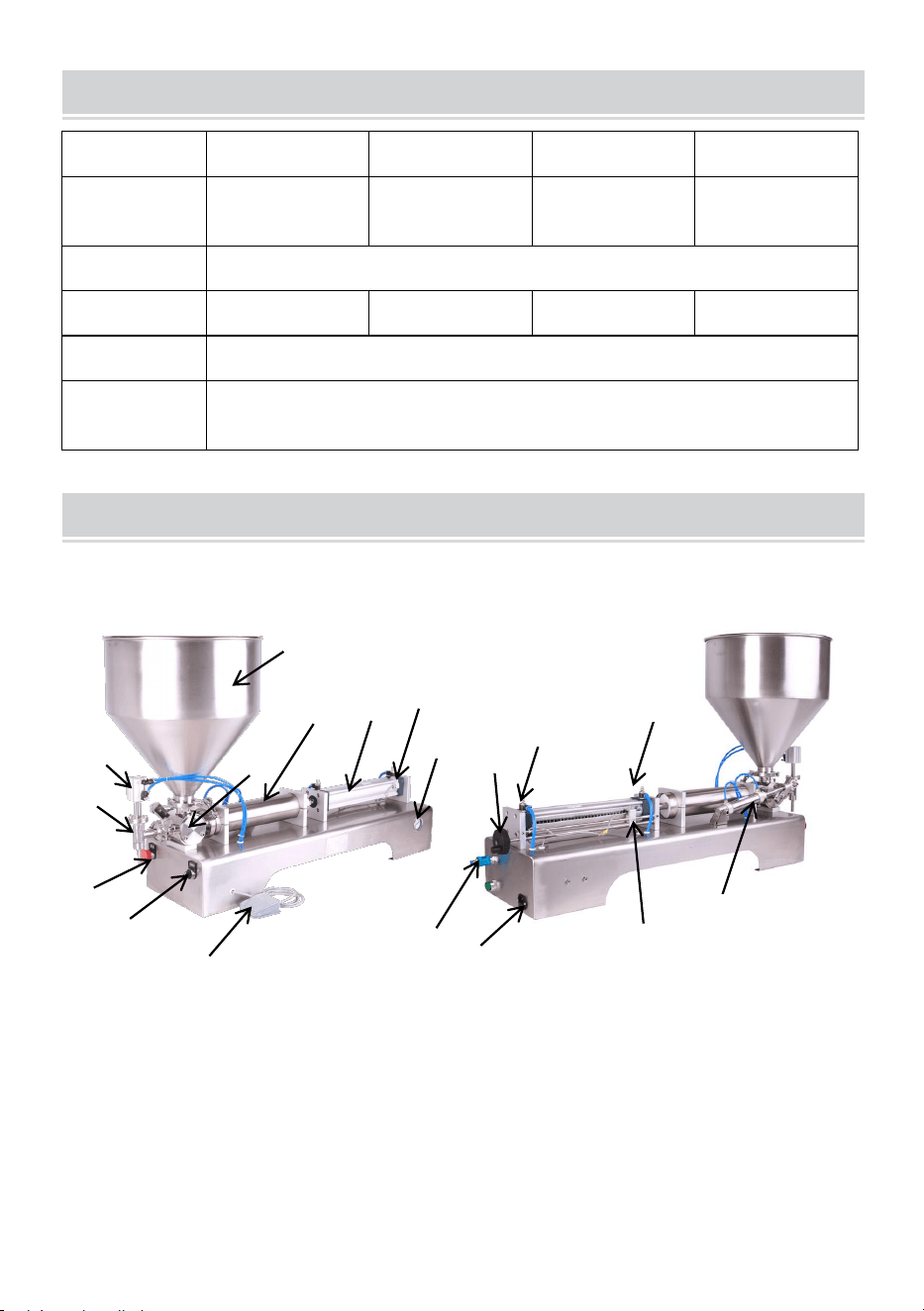
- 4 -
MODEL AND PARAMETERS
Modell
G1WG-300
G1WG-500
G1WG-1000
G1WG-5000
Fyllningso
mråde
30-300 ml
50-500ml
100-1000ml
500-5000 ml
Spänning
AC 120V 60Hz
Driva
10W
10W
10W
10W
Lufttryck
0,4-0,6MPA
Fyllningsh
astighet
10-30 flaskor/min
STRUCTURE DIAGRAM
G1WG-300, G1WG-500, G1WG-1000, G1WG-5000
8. H opper 2. Vridventil 3. Påfyllningshuvud 4. Cylinder för
påfyllningshuvud 5. Nödstopp 6. Jogging och automatiska lägen 7.
Fotkontakt 8. Cylinderpipa 9. Primär luftcylinder 10. Pneumatisk
ventil
18.Elkontakt 12. Cylindern som styr vridventilen
13. Strypventil NO.1 14. Strypventil NO.2 15. magnetomkopplare NO.1
16.Hand joystick 17.Barometer 18. magnetomkopplare NO.2
1
4
2
3
6
7
8
9
10
5
11
12
13
14
17
16
15
18
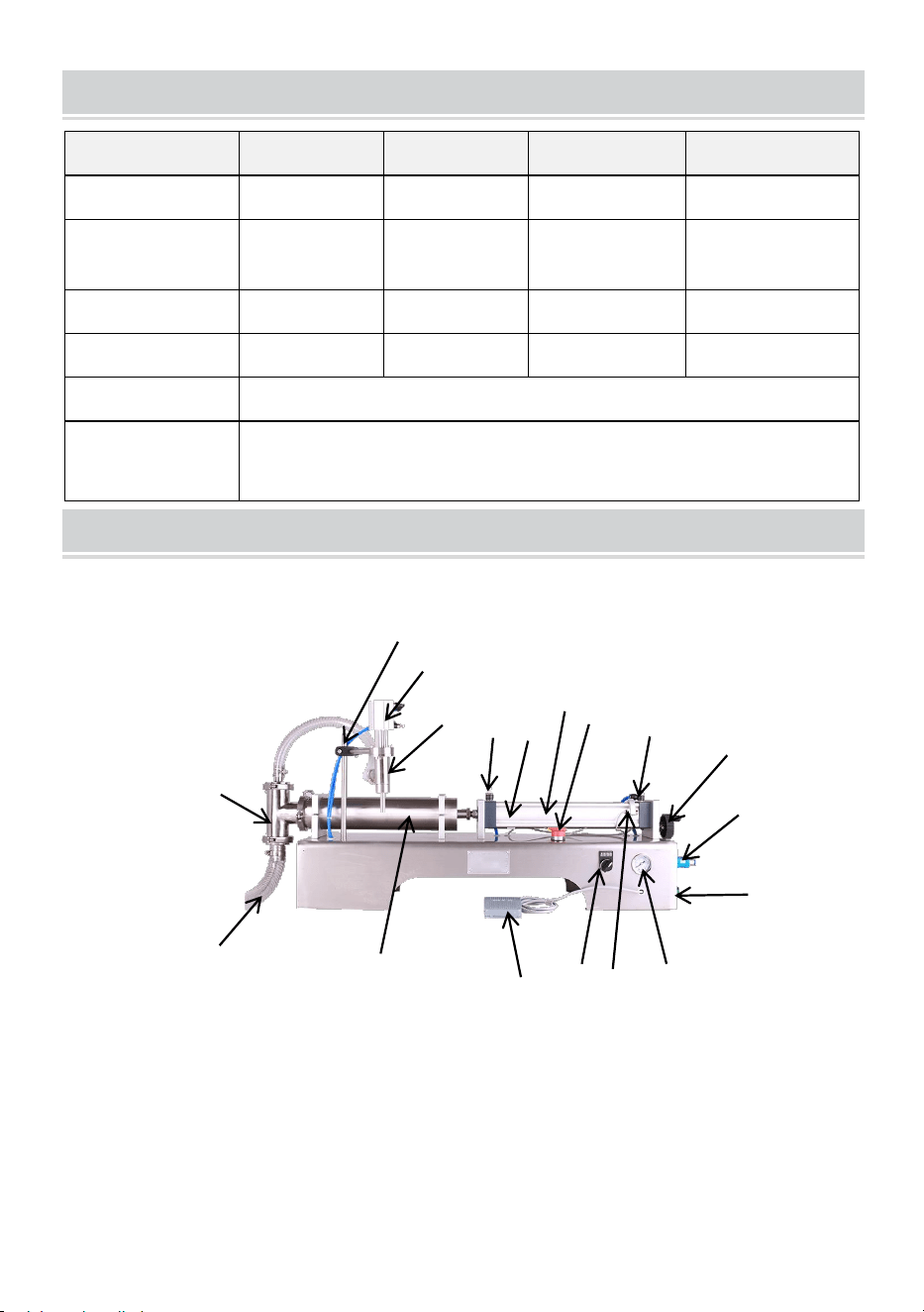
- 5 -
MODEL AND PARAMETERS
Modell
G1WY-500
G2WY-500
G2WY-1000
G2WY-1000
Fyllningsområ
de
50-500ml
50-500ml
100-1000ml
100-1000ml
Spänning
AC 120V
60Hz
AC 120V
60Hz
AC 120V
60Hz
AC 230V
50Hz
Driva
10W
20W
20W
20W
Antal huvud
Enda
D ouble
D ouble
D ouble
Lufttryck
0,4-0,6MPA
Fyllningshasti
ghet
Enkelt huvud: 10-30 flaskor/min
dubbla huvuden: 20-60 flaskor/min
STRUCTURE DIAGRAM
1. Matarrör 2. trevägsventil 3. Påfyllningshuvud 4. Cylinder för
påfyllningshuvud 5. Nödstopp 6. Jogging och automatiska lägen 7.
Fotkontakt 8. Cylinderpipa 9. Primär luftcylinder 10. Pneumatisk
ventil
11. Strömkontakt 12.stöd 13. Strypventil NR.1
14. Strypventil NO.2 15. magnetomkopplare NO.1
2
5
1
15
10
8
12
3
14
11
16
9
13
17
4
6
7
18
G1WY-500, G2WY-500, G2WY-1000

- 6 -
16.Hand joystick 17.Barometer 18. magnetomkopplare NO.2
OPERATING INSTRUCTIONS
Steg 1:
15) G1WG-300,G1WG-500,G1WG-1000,G1WG-5000
Installation och fixering av tratten .
16) G1WY-500,G2WY-500,G2WY-1000
Anslut matningsröret och det fasta påfyllningshuvudet :
Steg 2: Anslut strömförsörjningen och var uppmärksam på spänningen .
Anslut luftkompressorn och för in luftröret i den pneumatiska ventilen. När
du trycker reglaget inåt är maskinen ansluten till luftkällan; Dra
skjutreglaget utåt och koppla bort lufttillförseln från maskinen.
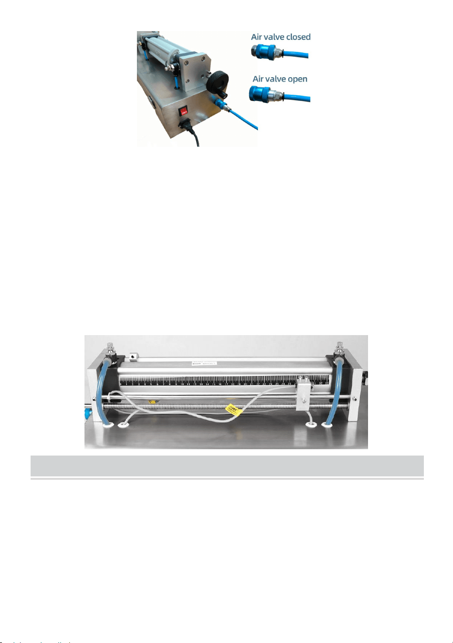
- 7 -
Steg 3 : Justera fyllningsvolym och fyllningshastighet. När joysticken vrids
moturs kommer magnetomkopplaren (NO.1) att flyttas framåt, vilket ökar
påfyllningsmängden. När joysticken vrids medurs kommer
magnetomkopplaren (NO.1) att flyttas bakåt, vilket minskar
påfyllningsmängden. Observera att vid justering bör magnetomkopplarens
position (NO.1) inte vara för framåt eller för bakåt, eftersom den inte kan
fungera utanför maskinens fyllningsområde. Vridning av gasspjällsventilen
(NO.2) medurs kommer att sakta ner hastigheten på cylindern som trycker
ut, det vill säga utloppshastigheten kommer att sakta ner. Det motsatta är
också sant. Vridning av gasspjällsventilen (NO.1) medurs kommer att
sakta ner cylinderns indragningshastighet. Det motsatta är också sant.
MAINTENANCE
22. Efter användning ska maskinens yta rengöras och restmaterial inuti
maskinen tas bort. Stoppa inte fingrarna i den roterande ventilen under
rengöring .
23. Vid förvaring, förvara på en ren, torr och säker plats borta från barn.
24. Allt underhåll, service och reparationer som inte diskuteras i manualen
bör endast utföras av kvalificerad servicetekniker .

- 8 -
TROUBLESHOOTING
Problem
Möjlig orsak
Möjlig lösning
Luftcylindern gör
det inte arbete
Luftkompressorn är
inte påslagen
Öppna luftkompressorns ventil
Den pneumatiska
ventilen är inte öppen
Tryck den pneumatiska ventilen
(10) inåt
Nödstoppsbrytare
inte släppt
Släpp nödstoppsbrytaren
Magnetbrytarens läge
(NO.2) är löst
Flytta magnetomkopplaren (NO.2)
åt vänster och höger tills maskinen
kan starta, säkra sedan
magnetbrytaren igen
Strypventilen (NO.2)
har dragits åt
Vrid gasspjällsventilen (NO.2)
moturs
Cylindern är
blockerad
Rengör insidan av cylinderröret
Cylindern som styr
rotationsventilen
rör sig inte
Förslitning av
rotationsventilens
ventilkärna
Ta ut ventilkärnan för polering
Påfyllningshuvudet
kan inte producera
material
Påfyllningshuvudet är
blockerat inuti
Demontera och rengör
påfyllningshuvudet
Påfyllningshuvudets
cylinder är trasig
Byte av cylinder
När cylindern
skjuts framåt kan
den inte komma
tillbaka
Magnetströmbrytaren
är trasig
Byt ut magnetomkopplaren (NO.1)
Magnetbrytarens läge
är felaktigt
Flytta magnetomkopplaren (NO.1)
bakåt
Adress: Baoshanqu Shuangchenglu 803long 11hao 1602A-1609shi
Shanghai

- 9 -
Importerad till AUS: SIHAO PTY LTD . 1 ROKEVA STREETEASTWOOD
NSW 2122 Australien
Importerad till USA: Sanven Technology Ltd. Svit 250 . 9166 Anaheim
Place, Rancho Cucamonga, CA 91730
REP
EC
SHUNSHUN GmbH
Römeräcker 9 Z2021, 76351
Linkenheim-Hochstetten, Germany
REP
UK
Pooledas Group Ltd
Unit 5 Albert Edward House, The
Pavilions Preston, United Kingdom
Tillverkad i Kina

