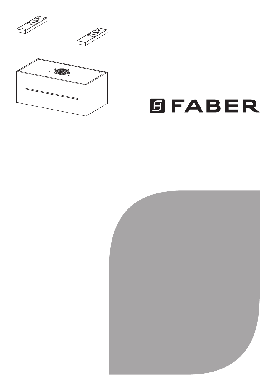
GRAZIS30BKV
Installation Instructions
Use and Care Information
Instructions d'installation
Utilisez et d'entretien
Instrucciones de instalación
Información de uso y cuidado
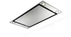
GRAZIOSA ISOLA

2
CONTENTS
Section Page
Important safety instructions
3
Range hood dimensions
7
Installation height requirements
8
Parts
9
Tools needed
11
Ceiling hood install preparation
12
Installation information
14
Installation of range hood body
15
Ceiling mounting instructions
17
Electrical connections
24
Operating the controls
27
Faber Cloud App
31
Remote control
32
Cleaning stainless steel
32
Maintenance
33
Replacing lighting
34
Wiring diagram
35
Warranty
36

3
IMPORTANT SAFETY INSTRUCTIONS
READ AND SAVE THESE INSTRUCTIONS BEFORE YOU START
INSTALLING THIS RANGE HOOD
WARNING: - TO REDUCE THE RISK OF A RANGE TOP GREASE FIRE:
a) Never leave surface units unattended at high settings. Boilovers cause smoking and
greasy spillovers that may ignite. Heat oils slowly on low or medium setting.
b) Always turn hood ON when cooking at high heat or when flambeing food (i.e. Crepes
Suzette, Cherries Jubilee, Peppercorn Beef Flambé).
c) Clean ventilating fans frequently. Grease should not be allowed to accumulate on fan or
filter.
d) Use proper pan size. Always use cookware appropriate for the size of the surface element.
WARNING: - TO REDUCE THE RISK OF INJURY TO PERSONS IN THE EVENT OF A RANGE
TOP GREASE FIRE, OBSERVE THE FOLLOWING*:
a) SMOTHER FLAMES with a close-fitting lid, cookie sheet, or metal tray, then turn off
the burner. BE CAREFUL TO PREVENT BURNS. If the flames do not go out immediately
EVACUATE AND CALL THE FIRE DEPARTMENT.
b) NEVER PICK UP A FLAMING PAN - You may be burned.
c) DO NOT USE WATER, including wet dishcloths or towels - a violent steam explosion will
result.
d) Use an extinguisher ONLY if:
1. You know you have a Class ABC extinguisher, and you already know how to operate it.
2. The fire is small and contained in the area where it started.
3. The fire department is being called.
4. You can fight the fire with your back to an exit.
* Based on "Kitchen Firesafety Tips" published by NFPA
WARNING - TO REDUCE THE RISK OF FIRE OR ELECTRIC SHOCK, do not use this fan with
any solid-state speed control device.
WARNING - TO REDUCE THE RISK OF FIRE, ELECTRICAL SHOCK, OR INJURY TO PERSONS,
OBSERVE THE FOLLOWING:
1. Use this unit only in the manner intended by the manufacturer. If you have any questions,
contact the manufacturer.
2. Before servicing or cleaning unit, switch power off at service panel and lock the service
disconnecting means to prevent power from being switched on accidentally. When the
service disconnecting means cannot be locked, securely fasten a prominent warning
device, such as a tag, to the service panel.
CAUTION: For General Ventilating Use Only. Do Not Use To Exhaust Hazardous or Explosive
Materials and Vapors.
WARNING - TO REDUCE THE RISK OF FIRE, ELECTRICAL SHOCK, OR INJURY TO PERSONS,
OBSERVE THE FOLLOWING:
1. Installation Work And Electrical Wiring Must Be Done By Qualified Person(s)
In Accordance With All Applicable Codes And Standards, Including Fire-Rated
Construction.
2. Sufficient air is needed for proper combustion and exhausting of gases through the
flue (chimney) of fuel burning equipment to prevent backdrafting. Follow the heating

4
equipment manufacturer's guideline and safety standards such as those published by
the National Fire Protection Association (NFPA), and the American Society for Heating,
Refrigeration and Air Conditioning Engineers (ASHRAE), and the local code authorities.
3. When cutting or drilling into wall or ceiling, do not damage electrical wiring and
other hidden utilities.
4. Ducted fans used to exhaust contaminants must always be vented to the outdoors.
ALL WALL AND FLOOR OPENINGS WHERE THE RANGE HOOD IS INSTALLED MUST BE
SEALED.
This Range Hood requires at least 30" of clearance between the bottom of the Range Hood
and the cooking surface or countertop. This hood has been approved by UL at this distance
from the cooktop.
Consult the cooktop or range installation instructions given by the manufacturer before making
any cutouts. MOBILE HOME INSTALLATION The installation of this Range Hood must conform
to the Manufactured Home Construction and Safety Standards, Title 24 CFR, Part 3280 (formerly
Federal Standard for Mobile Home Construction and Safety, Title 24, HUD, Part 280).
Attention: This hood has been engineered to minimize electromagnetic interference (EMI)
originating from the consumer's home power source. However, in some home application,
ambient EMI and excessive EMI from other electronic sources can compromise the reliability
of the remote control.
Please speak with your Faber Distributor about an optional spare part to further reduce EMI
from home sources.
VENTING REQUIREMENTS
Determine which venting method is best for your application. Ductwork can extend either
through the wall or the roof.
The length of the ductwork and the number of elbows should be kept to a minimum to provide
efficient performance. The size of the ductwork should be uniform. Do not install two elbows
together. Use duct tape to seal all joints in the ductwork system. Use caulking to seal exterior
walls and ceiling space opening around the cap.
Flexible ductwork is not recommended. Flexible ductwork creates back pressure and air
turbulence that greatly reduces performance.
Make sure there is proper clearance within the walls and ceiling space for exhaust duct before
making cutouts. Do not cut a joist or stud unless absolutely necessary. If a joist or stud must
be cut, then a supporting frame must be constructed.
WARNING - To Reduce The Risk Of Fire, Use Only Metal Ductwork.
CAUTION - To reduce risk of fire and to properly exhaust air, be sure to duct air outside – Do
not vent exhaust air into spaces within walls or ceilings or into attics, crawl spaces, or garages.
WARNING: To Reduce The Risk Of Fire, Electric Shock Or Injury To Persons, Do Not Use
Replacement Parts That Have Not Been Recommended By The Manufacturer (e.g. Parts
Made At Home Using A 3D Printer).
Cold Weather installations
An additional back draft damper should be installed to minimize backward cold air flow and a
nonmetallic thermal break should be installed to minimize conduction of outside temperatures
as part of the vent system. The damper should be on the cold air side of the thermal break.

5
• Electrical ground is required on this Range Hood.
• If cold water pipe is interrupted by plastic, nonmetallic gaskets or other
materials, DO NOT use for grounding.
• DO NOT ground to a gas pipe.
• DO NOT have a fuse in the neutral or grounding circuit. A fuse in the neutral or
grounding circuit could result in electrical shock.
• Check with a qualified electrician if you are in doubt as to whether the Range
Hood is properly grounded.
• Failure to follow electrical requirements may result in a fire.
WARNING
!
• Venting system MUST terminate outside the home.
• DO NOT terminate the ductwork in an attic or other enclosed space.
• DO NOT use 4" laundry-type wall caps.
• Flexible-type ductwork is not recommended.
• DO NOT obstruct the flow of combustion and ventilation air.
• Failure to follow venting requirements may result in a fire.
WARNING
!
ELECTRICAL REQUIREMENTS
A 120 volt, 60 Hz AC-only electrical supply is required on a separate 15 amp fused circuit. A
time-delay fuse or circuit breaker is recommended. The fuse must be sized per local codes in
accordance with the electrical rating of this unit as specified on the serial/rating plate located
inside the unit near the field wiring compartment.
ELECTRICAL INSTALLATION WITH WIRING BOX
THIS UNIT MUST BE CONNECTED WITH COPPER WIRE ONLY. Wire sizes must conform to
the requirements of the National Electrical Code, ANSI/NFPA 70 - latest edition, and all local
codes and ordinances. Wire size and connections must conform with the rating of the appliance.
Copies of the standard listed above may be obtained from:
National Fire Protection Association
Batterymarch Park
Quincy, Massachusetts 02269
This appliance should be connected directly to the fused disconnect (or circuit breaker) through
flexible, armored or nonmetallic sheathed copper cable. Allow some slack in the cable so the
appliance can be moved if servicing is ever necessary. A UL Listed, 1/2" conduit connector must
be provided at each end of the power supply cable (at the appliance and at the junction box).
When making the electrical connection, cut a 1 1/4" hole. A hole cut through wood must be
sanded until smooth. A hole through metal must have a grommet.
The break should be as close as possible to where the vent system enters the heated portion
of the house.

6
CAUTION: Accessible parts may become hot when used with cooking appliances.
•Theairmustnotbedischargedintoauethatisusedforexhaustingfumesfrom
appliancesburninggasorotherfuels
•lfaSTATIONARYAPPLIANCEisnotttedwithaSUPPLYCORDandaplug,
orwithothermeansfordisconnectionfromthesupplymainshavingacontact
separationinallpolesthatprevidefulldisconnectionunderovervoltagecategory
lIIconditions,theinstructionsshallstatethatmeansfordisconnectionmustbe
incorporatedinthexedwiringinaccordancewiththewiringrules.
•The disconnection may be achieved by having the plug accessible or by
incorporatingaswitchinthexedwiringinaccordancewiththewiringrules.
• Thisdeviceisnotintendedforusebypersons(includingchildren)whosephysical,
sensoryormentalabilitiesaredifferentorreduced,orwholackexperienceor
knowledgeunlesssuchpersonsreceivesupervisionortrainingfortheoperation
ofthedevicebyapersonresponsiblefortheirsafety.
•Childrenshouldbesupervisedtoensuretheydonotusethedevicesasatoy.
•Donotamefoodundertherangehood.
•theairmustnotbedischargedintoauethatisusedforexhaustingfumesfrom
appliancesburninggasorotherfuels(notapplicabletoappliancesthatonly
dischargetheairbackintotheroom);
•thereshallbeadequateventilationoftheroomwhentherangehoodisused
atthesametimeasappliancesburninggasorotherfuels(notapplicableto
appliancesthatonlydischargetheairbackintotheroom);
•thereisareriskifcleaningisnotcarriedoutinaccordancewiththeinstructions;
•Thisappliancemust be grounded. In the event ofanelectrical short circuit,
groundingreducestheriskofelectricshockbyprovidinganescapewireforthe
electriccurrent.Thisapplianceisequippedwithacordhavingagroundingwire
with a grounding plug. The plug must be plugged into an outlet that is properly
installed and grounded.
WARNING-lmpropergroundingcanresultinariskofelectricshock.
•Consultaqualiedelectricianifthegroundinginstructionsarenotcompletely
understood,orifdoubtexistsastowhethertheapplianceisproperlygrounded.

7
17-Oct-2024
Released
RANGEHOODDIMENSIONS
8
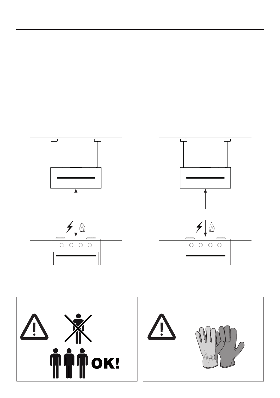
INSTALLATION HEIGHT REQUIREMENTS
Recommended 30" mounting height above the cooking surface for best performance,
but can be mounted up to 72" maximum away the cooking surface.
An access point to the hood from the ceiling or soffit must be made for installation
and future access to the range hood.
MIN. 30" OVER ELECTRIC / GAS
Non Ducted Installation
This hood is designed to be mounted on the ceiling, and in Recirculation mode only.
Three people required for installation Wear work gloves for safety
MAX. 72" OVER ELECTRIC / GAS

9
PARTS
PARTSINCLUDED
REF. PART QTY
A
Hood Body, complete with: Controls, Lights, Filters. 1
E
Remote Control 1
H
Drilling Template 1
L
Ceiling bracket 2
I
Ceiling cable 4
REF
PART
QTY
C
Screws 4/16" x 2-12/16" 8
O
Transparent stopper 1
O1
Stopper 1
P
Screws 2/16" x 4/16" 2
R1
Terminal cover 1
W
Charcoal Filter 2

10
8
AA-725973-1
1x
1x
C
1x
B
A
1x
3x 4x
1x
D E
1x
1x
1x
1x
H
O
I
A
E
L
W
R1
O1
11
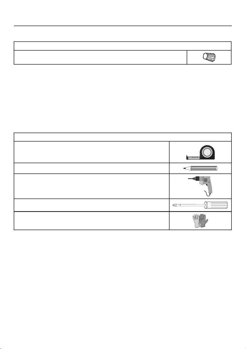
PARTSNEEDED
PARTS(cont.)
PART
Wire connectors.
TOOLSNEEDED
TOOL
Tape Measure
Pencil
Electric Drill with 5/16" Drill Bit
Phillips Screwdriver
Work gloves
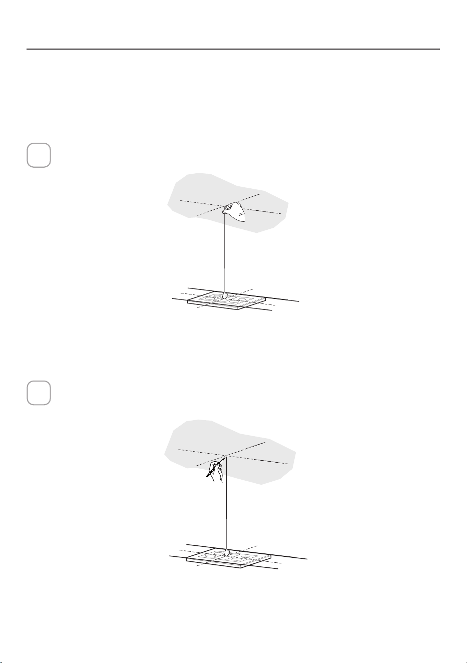
12
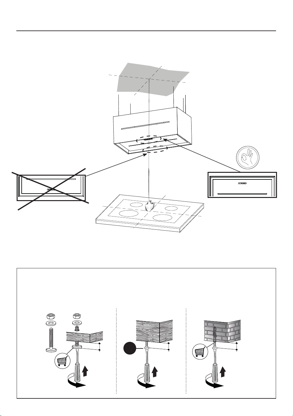
Use a plumb line to mark the center of the range on the ceiling.
1
CEILINGHOODINSTALLPREPARATION
Mark the center.
2
Do not make any cutouts until you have decided whether this installation will be:
non-ducted and wiring has been prepared based on based on blower type.
13
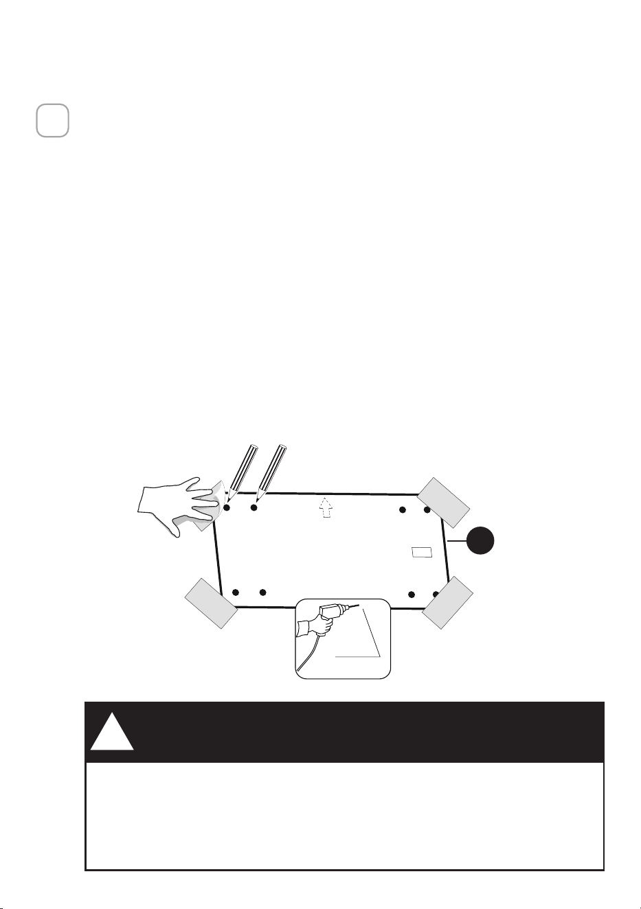
DUE TO THE SIZE AND WEIGHT OF THIS Range Hood, THE SUPPORT
MUST BE FIRMLY ATTACHED TO THE CEILING. For plaster or sheet
rock ceiling, the support must be attached to the joists. If this is not
possible, a support structure must be built behind the plaster or sheet
rock. The manufacturer assumes no responsibility for injury or damage
caused by improper installations.
WARNING
!
• Put a thick, protective covering over cooktop to protect from damage or
dirt.
• Use the mounting template on the ceiling to determine placement of
mounting screws on the ceiling.
• Mark the center of the holes in the ceiling template.
• Determine the proper location for the Power Supply Cable as indicated on
the Template.
• Use a 3/8" Drill Bit to make this hole.
• Run the Power Supply Cable. Use caulking to seal around the hole.
• A knockout for threading through the Power Supply from the ceiling is
located on the top of the Range Hood.
• Do not connect the Power Cable to the Wiring Box or power up the hood
at this time.
• Run enough power cable from the ceiling to reach the wiring box on the
hood.
3
H
3/8"
14
INSTALLATION INFORMATION
In preparation for installation of the hood, orient the hood with the control panel
on the front of hood as shown below.
CORRECT
NOT
CORRECT
Use only screws and small parts in support of the hood.
Warning: Failure to install the screws in accordance with these instructions may
result in electrical hazards.
OK!
3/16"
OK!
3/16"
OK!
3/16
"
C
15
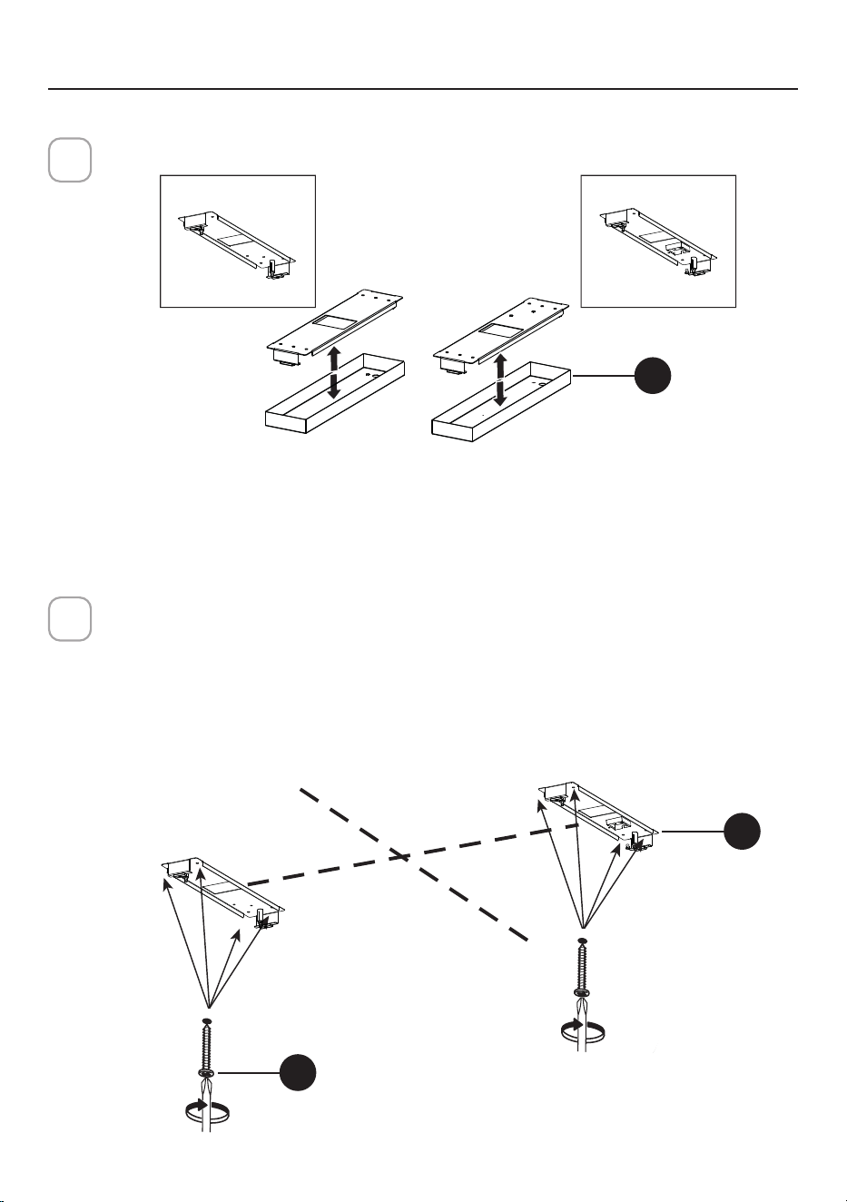
I = 8X
8X
Ø10mm
DXSX
DX
INSTALLATIONOFRANGEHOODBODY
Remove the cover of the ceiling brackets (L).
4
Left Right
Installation on the Ceiling
Use holes created with drilling template for location of the ceiling fasteners.
Use a 5/16" Drill Bit to make these hole.
Use wall plugs if appropriate or other securing hardware in conjunction with
the ceiling fasteners (purchased separately).
Attach the brackets to the ceiling (L) with the 8 screws (C) into the brackets
until tight and secure.
5
L
DX
SX
L= 4X
L= 4X
C
L
Left
Right

16
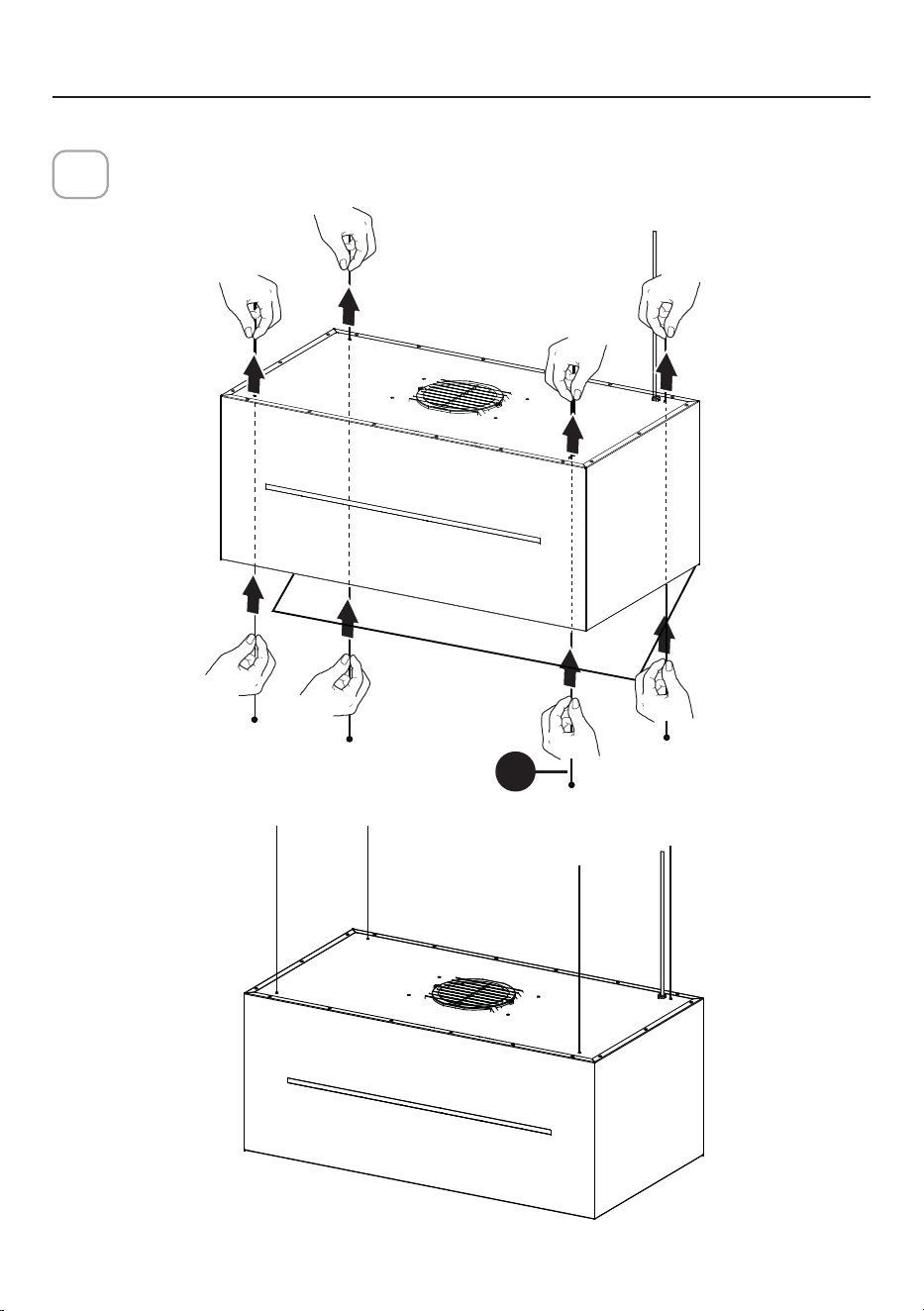
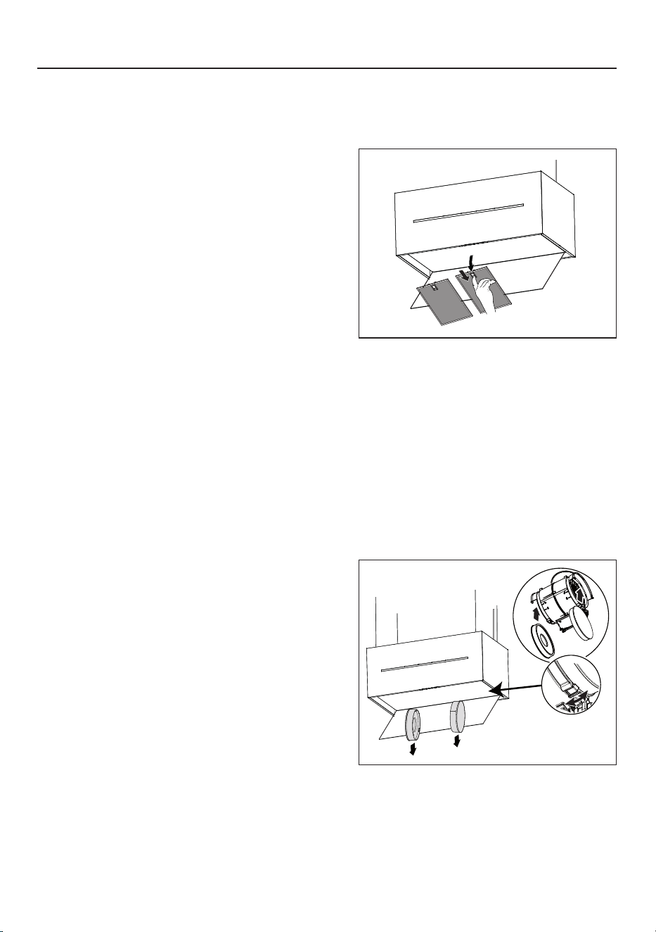
Open the filter cover panel.
The filter cover panel is held by a magnet catch, pull down with enough
force to release as shown below.
6
Remove the grease filters.
7
17
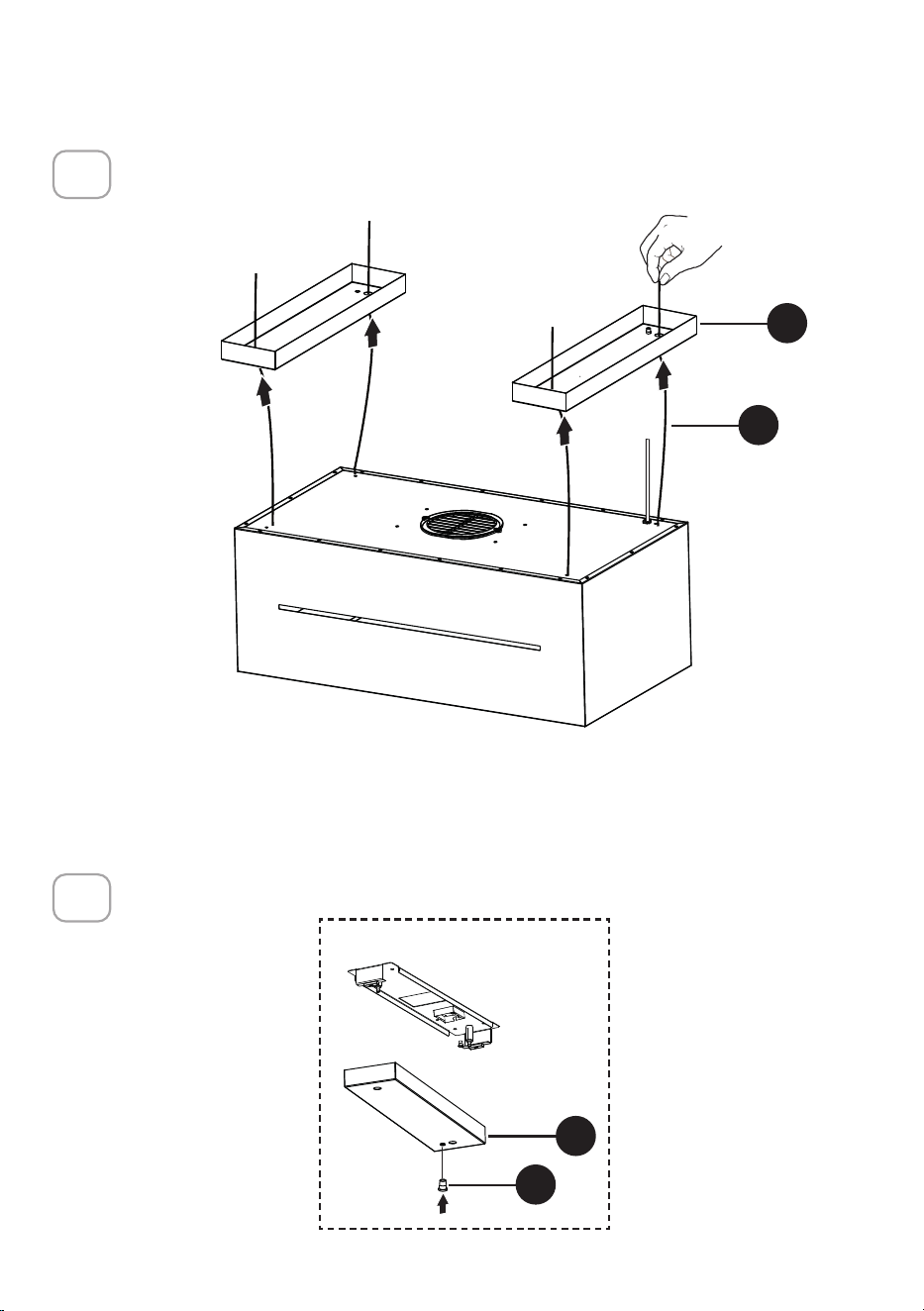
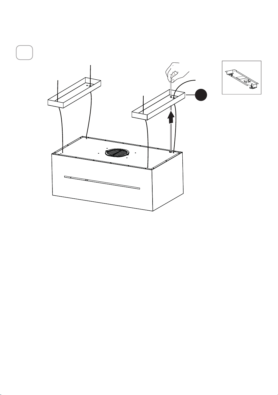
Insert ceiling cables (I) thru the range hood bottom and out of the top of
the hood.
8
CEILING MOUNTING INSTRUCTIONS
I
18
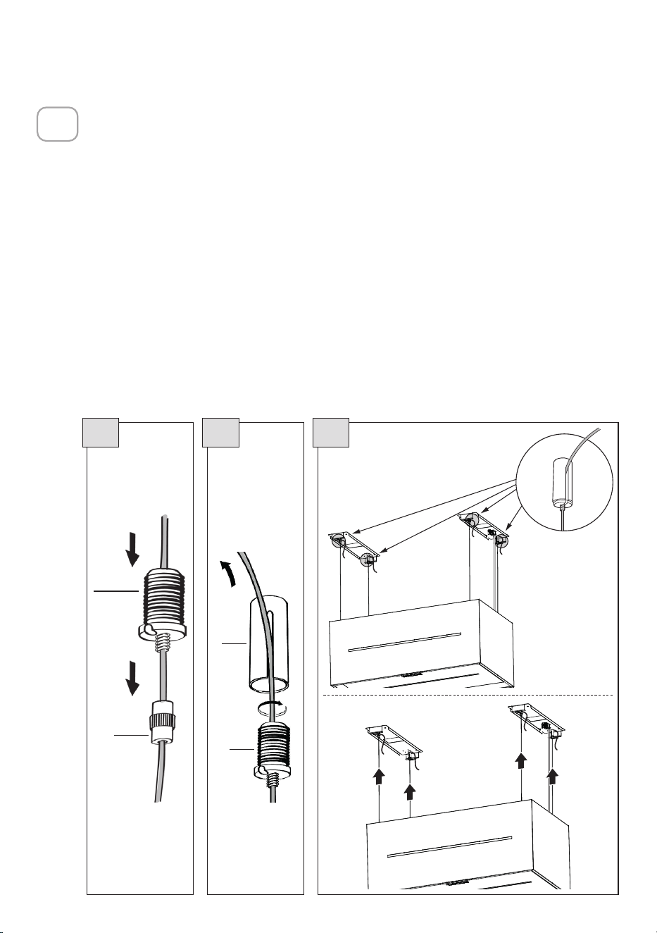
Insert the cables (I) into the four holes on ceiling bracket covers (L).
9
Insert in the transparent plug (O) in the right cover of the ceiling brackets (L).
10
4x
DXSX
I
L
DXSX
O
L
Right
DX
19
Insert in the cover of the right ceiling bracket (L) the Power Supply Cable.
11
L
I = 8X
8X
Ø10mm
DX
SX
DX
Right

20
CONNECTING HOOD-PLATE CABLES
ATTENTION! Before continuing with installation it is necessary to move the
hood to a height of at least 30" from the electric and the gas cooking surface,
using a support or the assistance of another person.
This is essential, as the hood cables must necessarily be connected to the plate
fitted to the ceiling without the weight of the hood bearing on the structure.
The cable fixing system is made up of 3 parts:
• Threaded Pawls (A1) already mounted on the ceiling brackets.
• Cable clamp screws (B1) provided (D1).
• Safety knobs (C1) provided (D1).
12
4x
A1
B1
C1
D1
4x
21
CONNECTING HOOD-PLATE CABLES
FITTING THE HOOD BODY
• Insert the cables into the safety knobs (C1) with the thread at the top (Fig. 15.1).
• Insert the cables into the cable clamp screws (
B1
) (Fig. 15.1).
• Pass the cables through the slots in the threaded pawls (
A1
) and screw the
cable locking screws (
B1
) to the pawls themselves (Fig. 15.2).
• When the operation has been completed the result must be as shown in the
figure for all 4 cables (Fig. 15.3).
• At this point we have all 4 cables connected to the ceiling brackets.
Bring the cables under tension by pushing them upwards so that they slide inside
the cable clamp screw and slide out of the slot in the threaded pawl.
This is possible because the cable clamp screw has a system that, if mounted
properly, allows the cables to slide inside it in one direction only, and prevents it
from sliding in the other direction.
Attention, the cables all have the same length to facilitate the operation of the final
level. The front left cable must not be slacker than the others.
13
B1
C1
15.1 15.2 15.3
A1
B1

22
LEVELLING THE HOOD
• The hood is levelled by adjusting the safety pawls.
• Rest a level on the hood.
• When the safety knobs are pressed upwards, movement of the hood is
“unlocked”. By inserting or extracting the cable from the cable clamp
screw it is possible to make adjustments that allow the mobile hood
body to be levelled.
• Once the hood has been set level, the safety knobs must be tightened
again.
14
4x
Warning:
• Please check that all 4 cables are stretched.
• Please check that all 4 cables were not damaged during installation.
• Please DO NOT cut the excess part of each cable.
• It must be remembered that the minimum distance between the hood
and the cooking hob must be 30" from the electric and gas cooking
surface.
1
2
1
2
4x
23
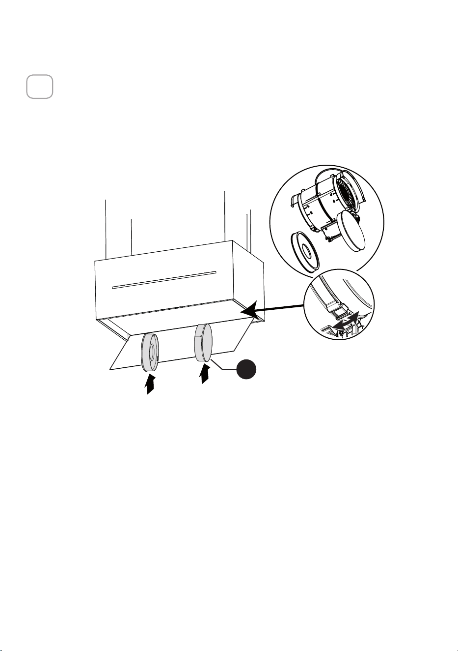
INSTALLATION OF CHARCOAL FILTERS
Non-Ducted Recirculation Only
• Open the lighting unit by pulling on the notch provided.
• Remove the grease filters.
• Make sure that the Activated charcoal filters been fitted.
• See also "Maintence" paragraph.
15
W
24
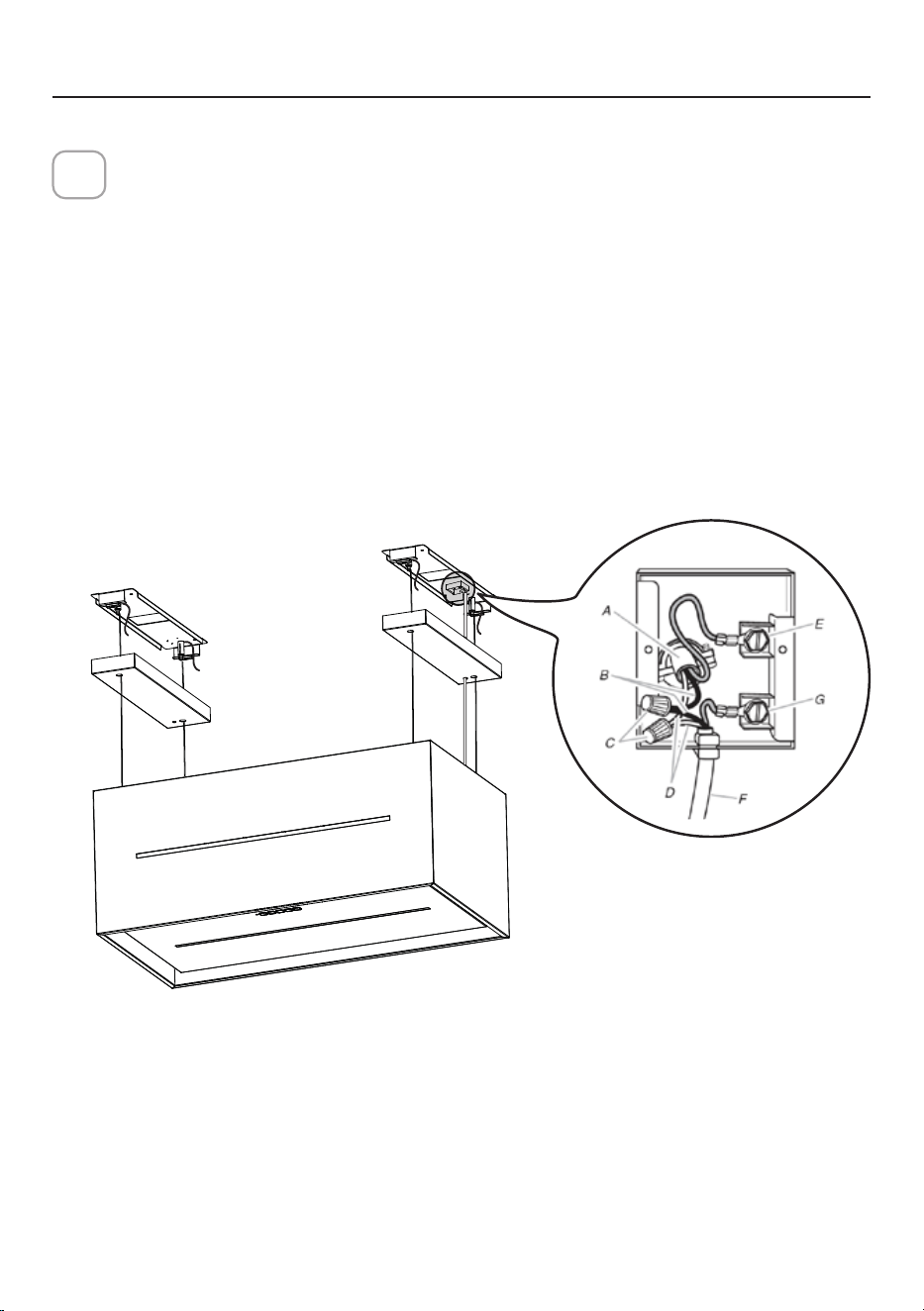
ELECTRICAL CONNECTIONS
Installation of wiring connection
Remove the cover from the field wiring compartment.
DO NOT turn on the power until installation is complete!
Connect the Power Supply Cable to the rangehood.
Connect the Green (Green and Yellow) ground wire under the Green
grounding screw. Attach the White lead of the power supply to the White
lead of the rangehood with a twist-on type wire connector.
Attach the Black lead of the power supply to the Black lead of the
rangehood with a twist-on type wire connector.
Replace the field wiring compartment cover and the grease filters.
16
A. Home power supply cable
B. Black wires
C. UL listed wire connectors
D. White wires
E. Green (or bare) ground wire from home power supply connected to
green ground screw
F. Range hood power supply cable
G.Range hood power supply cable connected to green ground screw.
Version 02/12 - Page 8
FIGURE 13
MAKE THE ELECTRICAL CONNECTION
Remove the cover from the eld wiring compartment. (SEE
FIGURE 11) DO NOT turn on the power until installation is
complete! Connect the Power Supply Cable to the rangehood.
Connect the Green (Green and Yellow) ground wire under the
Green grounding screw. Attach the White lead of the power
supply to the White lead of the rangehood with a twist-on type
wire connector. Attach the Black lead of the power supply
to the Black lead of the rangehood with a twist-on type wire
connector.
1. The UPPER CHIMNEY
COVER (C in FIGURE 13)
attaches to the top of the
support structure using two
screws provided (G in FIGURE
13). If using the High Ceiling
Chimney Kit, use the UPPER
CHIMNEY COVER supplied
with the kit. Slide up and
attach the UPPER CHIMNEY
COVER.
2. Attach the duct work to the
DAMPER (M in FIGURE 1).
Make sure to seal all joints with
duct tape to prevent leaks.
3. The LOWER CHIMNEY
COVER (B in FIGURE 13)
attaches using two screws
provided (G in FIGURE 13).
Install the LOWER CHIMNEY
COVER by sliding it up over
the support and the UPPER
CHIMNEY COVER.
For ductless installations, line up the DUCTLESS DIVERTER
EXTENSIONS HORIZONTAL (B in FIGURE 12) with the holes
in the LOWER CHIMNEY COVER (D in FIGURE 12) and snap
in the VENT GRIDS (C in FIGURE 12).
INSTALLING THE RANGEHOOD
A. Home power supply cable
B. Black wires
C. UL listed wire connectors
D.White wires
E. Green (or bare) ground wire from home power supply
connected to green ground screw
F. Range hood power supply cable
G.Range hood power supply cable connected to green
ground screw
FIGURE 11
Ductless installations require
a Ductless Conversion
Kit whose components are
pictured in FIGURE 12. Do
not use the DAMPER (M
in FIGURE 1) for ductless
installations. The LOWER
CHIMNEY COVER ( B
in FIGURE 1) should be
discarded and replaced by
the new one with holes from
the Ductless Conversion Kit
(D in FIGURE 12).
As indicated in FIGURE
12, place the DUCTLESS
DIVERTER (A) over the
exhaust opening of the EASY
CUBE (E). Fit the DUCTLESS
DIVERTER EXTENSIONS
HORIZONTAL (B) into the
DIVERTER (A).
FIGURE 12
FOR DUCTLESS INSTALLATIONS

25
Insert the stopper (O1) in the power cable and insert all in the wiring
connection.
Close the wiring connection with the terminal cover (R1) and attach it with 2
screws (P).
17
Replace the cover of the ceiling brackets (L).
18
L
R1
P
O1

26
Replace the grease filters.
19
Close the filter cover panel.
20
27
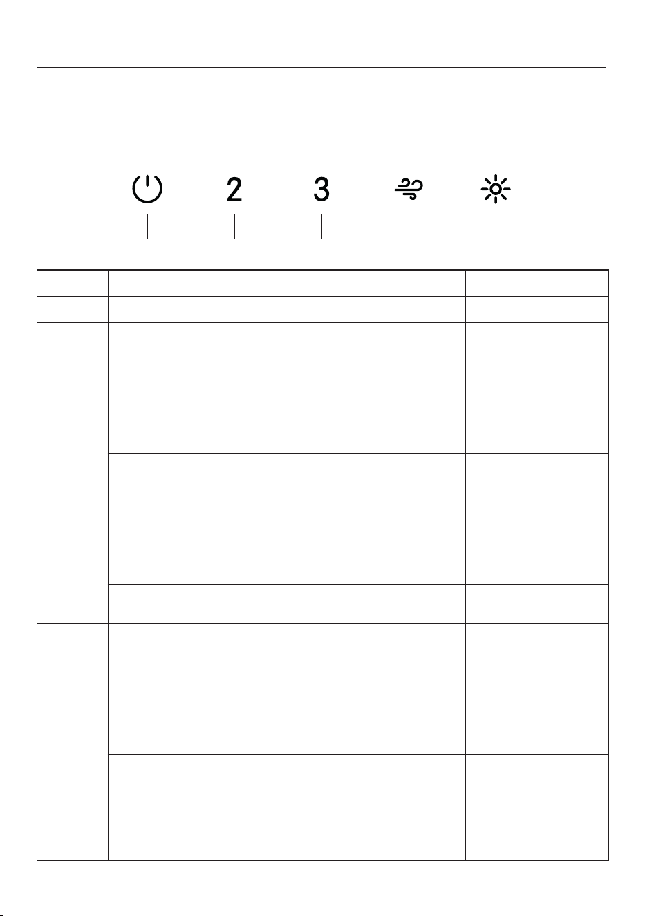
OPERATING THE CONTROLS
FOR BEST RESULTS
Start the Range Hood several minutes before cooking to develop proper airflow.
Allow the Range Hood to operate for several minutes after cooking is complete to
clear all smoke and odors from the kitchen.
BUTTON FUNCTION LED
A
Turns the motor on/off at the first speed. Solid.
B
Turns the motor on at the second speed. A and B solid.
Long press when light is on:
Activates/Deactivates the Activated Carbon Filters
alarm.
All Led's flashes
twice: alarm
activated.
All Led's flashes
once: alarm
deactivated.
Long press when all loads are off (Motor+Light):
Activates/Deactivates the Wi-Fi Connection function.
Note: the Wi-Fi function is automatically activated when
the user requests the Wi-Fi configuration procedure.
Led E Flashing:
connection to
domestic network in
progress.
Led E solid: Wi-Fi
connection activated.
C
Turns the motor on at the third speed. A and C solid.
Long press when motor is off:
The Filter saturation alarm is reset.
All Led's flash 3
times.
D
Turns the motor on at the Intensive speed.
This speed is timed for 6 minutes. At the end of the
time, the system automatically returns to the previously
selected speed. If activated with the motor off, once the
time has elapsed, it switches to OFF mode.
It is deactivated by pressing the same button or by
switching off the motor.
Flashing.
Signals the saturated Metal Grease Filters alarm and the
need to wash them. The alarm is activated after 100 hours
of effective hood operation.
Led's B and D
flashing.
Signals the saturated Activated Carbon Odour Filter
alarm. The alarm is activated after 200 hours of effective
hood operation.
Led's A and D
flashing.
A CB D E
28
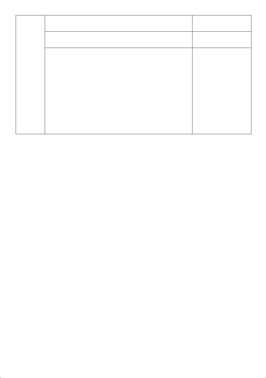
E
Short press: the lights alternate between high intensity,
medium intensity and off.
Solid.
Long press with all loads on (motor and lights):
Activates/Deactivates the Ambient Lights.
-
Long press with all loads off (motor and lights):
Wi-Fi configuration
Activates/Deactivates the Wi-Fi set-up procedure.
Before starting the procedure use the Faber Cloud
App to register with the IOT Faber system. Then follow
the instructions to add a new device and register the
domestic router.
If the procedure is not successfully completed within a
few minutes, deactivate it by long pressing the key again,
then make another attempt. The hood will nonetheless
abandon the procedure if it is not successfully completed
within 15 minutes.
Led's D and
E flashing:
configuration
procedure in
progress.
Upon successful
completion of the
procedure Led's D
and E will light up for
2 seconds.
29
WI-FI INFORMATION
This device complies with Part 15 of the FCC rules. Operation is subject to the
following two conditions: (1) this device may not cause harmful interference, and (2)
this device must accept any interference received, including interference that may
cause unwanted operation.
Note: This equipment has been tested and found to comply with the limits for
a Class B digital device, pursuant to Part 15 of the FCC Rules. These limits are
designed to provide reasonable protection against harmful interference in a
residential installation. This equipment generates, uses and can radiate radio
frequency energy and, if not installed and used according to the instructions,
can cause harmful interference to radio communications. However, there is no
guarantee that interference will not occur in a particular installation.
If this equipment causes harmful interference to radio or television reception, which
can be determined by turning the equipment off and on again, the user is invited to
try to correct the interference by taking one or more of the following measures:
• Reorient or reposition the receiving antenna.
• Increase the separation between the equipment and the receiver.
• Connect the equipment to an outlet on a circuit other than the one to which
• the receiver is connected.
• Consult your dealer or an experienced radio/TV technician for assistance.
Modifications to this product not authorized by Faber may invalidate
electromagnetic compatibility (EMC) and wireless compliance and deny permission
to use the product.
This product demonstrated EMC compliance under conditions that included the use
of compliant peripheral devices and shielded cables between system components.
It is important to use compliant peripherals and shielded cables between system
components to reduce the possibility of causing interference to radios, televisions,
and other electronic devices.
Exposure to radio frequency energy. The radiated output power of this device
meets the limits of FCC & IC radio frequency exposure limits. This device should
be used with a minimum separation distance of 20 cm (8 inches) between the
equipment and a person's body.
Connected Appliance Information
Contains FCC ID: 2AC7Z-ESPS3WROOM1
Contains IC: 21098-ESPS3WROOM1
Model: ESP32-S3-WROOM-1
CAN ICES-003(B)/NMB-003(B)
30
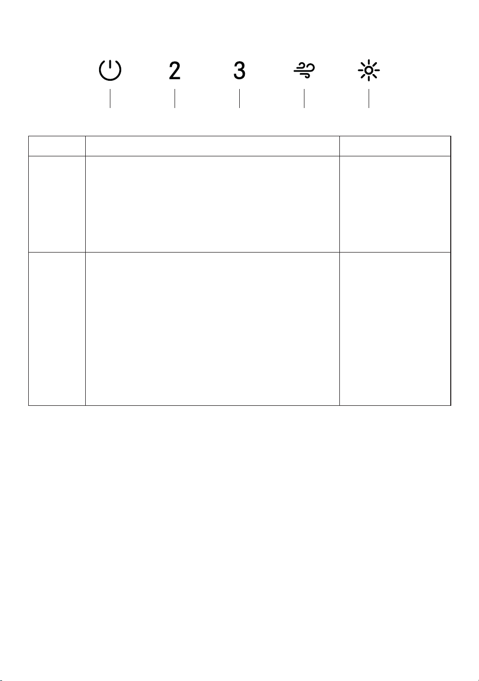
WI-FI CONNECTIONS
A CB D E
BUTTON FUNCTION LED
B
Activate / Deactivate the Wi-Fi Connection function.
A long Press of the speed 2 button with motor and
lights Off to activate / deactivate the WI-FI.
Note: the Wi-Fi function is automatically activated
when the user requests the Wi-Fi configuration
procedure.
Led's D + E flashing:
Connection to home
wireless router in
progress.
Led's D + E solid:
Wi-Fi connection
activated.
E
Starting the Wi-fi setup
A long press with the motor and lights Off to Enter or
End the Wi-Fi set-up procedure. Before starting the
procedure use the Faber Cloud App to register with
the IOT Faber system. Then follow the instructions
to add a new device and register your home wireless
router.
If the procedure is not successfully completed within
a few minutes, stop the set up process by holding the
intensive button for 3 seconds. Hold the button again
for 3 seconds to start the process. The hood will stop
the Wi-fi set up process if not successfully completed
within 15 minutes.
Led's D + E solid:
Set Up is in progress.
Led's D + E:
When setup is
finished LED’s stay lit
for 2 seconds.

31
FABER CLOUD APP
Faber Cloud App
Your range hood is compatible with the Faber Cloud app. All you need is a Internet
connected Wi-Fi network that is within range of the range hood. You can control all the
functions of your range hood from anywhere using a mobile device or your Amazon
Alexa or Google Home smart speaker. When connected to your smart speaker, you
can control your hood with your voice.
The Faber Cloud app is available on iOS devices using iOS 11.0 or later or Android
devices using Android version 8 or later. Visit the Apple App Store or Google Play
Store for more information. Your range hood will have full functionality if you are not
using the Wi-fi or the Faber CLoud App features, neither are required.
Please review the included Quick Connect Start Guide for more information.
Icon Function
5. FABER CLOUD APP
The Faber Cloud App is available for
iOS and Android smartphones and al-
lows remote access to all hood func-
tions.
Icon Function
Home page
Add new device
User profile management
Connected to Faber Wi-Fi network
Hood on/off
Lighting system management
Motor speed management
Intensive Function
24h Function
Delay Function
Automatic Function
App settings management
6. REMOTE CONTROL
• This appliance can be controlled us-
ing a remote control.
• ATTENTION: before proceeding, ac-
tivate K-Link Mode on the remote
control (see the device manual for
further details).
7. LIGHTING
• Please contact the Service Depart-
ment to change it ("Please contact
the service department to purchase
it").
8
Home page
5. FABER CLOUD APP
The Faber Cloud App is available for
iOS and Android smartphones and al-
lows remote access to all hood func-
tions.
Icon Function
Home page
Add new device
User profile management
Connected to Faber Wi-Fi network
Hood on/off
Lighting system management
Motor speed management
Intensive Function
24h Function
Delay Function
Automatic Function
App settings management
6. REMOTE CONTROL
• This appliance can be controlled us-
ing a remote control.
• ATTENTION: before proceeding, ac-
tivate K-Link Mode on the remote
control (see the device manual for
further details).
7. LIGHTING
• Please contact the Service Depart-
ment to change it ("Please contact
the service department to purchase
it").
8
Add new device
5. FABER CLOUD APP
The Faber Cloud App is available for
iOS and Android smartphones and al-
lows remote access to all hood func-
tions.
Icon Function
Home page
Add new device
User profile management
Connected to Faber Wi-Fi network
Hood on/off
Lighting system management
Motor speed management
Intensive Function
24h Function
Delay Function
Automatic Function
App settings management
6. REMOTE CONTROL
• This appliance can be controlled us-
ing a remote control.
• ATTENTION: before proceeding, ac-
tivate K-Link Mode on the remote
control (see the device manual for
further details).
7. LIGHTING
• Please contact the Service Depart-
ment to change it ("Please contact
the service department to purchase
it").
8
User profile management
5. FABER CLOUD APP
The Faber Cloud App is available for
iOS and Android smartphones and al-
lows remote access to all hood func-
tions.
Icon Function
Home page
Add new device
User profile management
Connected to Faber Wi-Fi network
Hood on/off
Lighting system management
Motor speed management
Intensive Function
24h Function
Delay Function
Automatic Function
App settings management
6. REMOTE CONTROL
• This appliance can be controlled us-
ing a remote control.
• ATTENTION: before proceeding, ac-
tivate K-Link Mode on the remote
control (see the device manual for
further details).
7. LIGHTING
• Please contact the Service Depart-
ment to change it ("Please contact
the service department to purchase
it").
8
Connected to Faber Wi-Fi network
5. FABER CLOUD APP
The Faber Cloud App is available for
iOS and Android smartphones and al-
lows remote access to all hood func-
tions.
Icon Function
Home page
Add new device
User profile management
Connected to Faber Wi-Fi network
Hood on/off
Lighting system management
Motor speed management
Intensive Function
24h Function
Delay Function
Automatic Function
App settings management
6. REMOTE CONTROL
• This appliance can be controlled us-
ing a remote control.
• ATTENTION: before proceeding, ac-
tivate K-Link Mode on the remote
control (see the device manual for
further details).
7. LIGHTING
• Please contact the Service Depart-
ment to change it ("Please contact
the service department to purchase
it").
8
Hood on/off
5. FABER CLOUD APP
The Faber Cloud App is available for
iOS and Android smartphones and al-
lows remote access to all hood func-
tions.
Icon Function
Home page
Add new device
User profile management
Connected to Faber Wi-Fi network
Hood on/off
Lighting system management
Motor speed management
Intensive Function
24h Function
Delay Function
Automatic Function
App settings management
6. REMOTE CONTROL
• This appliance can be controlled us-
ing a remote control.
• ATTENTION: before proceeding, ac-
tivate K-Link Mode on the remote
control (see the device manual for
further details).
7. LIGHTING
• Please contact the Service Depart-
ment to change it ("Please contact
the service department to purchase
it").
8
Lighting system management
5. FABER CLOUD APP
The Faber Cloud App is available for
iOS and Android smartphones and al-
lows remote access to all hood func-
tions.
Icon Function
Home page
Add new device
User profile management
Connected to Faber Wi-Fi network
Hood on/off
Lighting system management
Motor speed management
Intensive Function
24h Function
Delay Function
Automatic Function
App settings management
6. REMOTE CONTROL
• This appliance can be controlled us-
ing a remote control.
• ATTENTION: before proceeding, ac-
tivate K-Link Mode on the remote
control (see the device manual for
further details).
7. LIGHTING
• Please contact the Service Depart-
ment to change it ("Please contact
the service department to purchase
it").
8
Motor speed management
5. FABER CLOUD APP
The Faber Cloud App is available for
iOS and Android smartphones and al-
lows remote access to all hood func-
tions.
Icon Function
Home page
Add new device
User profile management
Connected to Faber Wi-Fi network
Hood on/off
Lighting system management
Motor speed management
Intensive Function
24h Function
Delay Function
Automatic Function
App settings management
6. REMOTE CONTROL
• This appliance can be controlled us-
ing a remote control.
• ATTENTION: before proceeding, ac-
tivate K-Link Mode on the remote
control (see the device manual for
further details).
7. LIGHTING
• Please contact the Service Depart-
ment to change it ("Please contact
the service department to purchase
it").
8
Intensive Function
5. FABER CLOUD APP
The Faber Cloud App is available for
iOS and Android smartphones and al-
lows remote access to all hood func-
tions.
Icon Function
Home page
Add new device
User profile management
Connected to Faber Wi-Fi network
Hood on/off
Lighting system management
Motor speed management
Intensive Function
24h Function
Delay Function
Automatic Function
App settings management
6. REMOTE CONTROL
• This appliance can be controlled us-
ing a remote control.
• ATTENTION: before proceeding, ac-
tivate K-Link Mode on the remote
control (see the device manual for
further details).
7. LIGHTING
• Please contact the Service Depart-
ment to change it ("Please contact
the service department to purchase
it").
8
Delay Function
5. FABER CLOUD APP
The Faber Cloud App is available for
iOS and Android smartphones and al-
lows remote access to all hood func-
tions.
Icon Function
Home page
Add new device
User profile management
Connected to Faber Wi-Fi network
Hood on/off
Lighting system management
Motor speed management
Intensive Function
24h Function
Delay Function
Automatic Function
App settings management
6. REMOTE CONTROL
• This appliance can be controlled us-
ing a remote control.
• ATTENTION: before proceeding, ac-
tivate K-Link Mode on the remote
control (see the device manual for
further details).
7. LIGHTING
• Please contact the Service Depart-
ment to change it ("Please contact
the service department to purchase
it").
8
24H function
5. FABER CLOUD APP
The Faber Cloud App is available for
iOS and Android smartphones and al-
lows remote access to all hood func-
tions.
Icon Function
Home page
Add new device
User profile management
Connected to Faber Wi-Fi network
Hood on/off
Lighting system management
Motor speed management
Intensive Function
24h Function
Delay Function
Automatic Function
App settings management
6. REMOTE CONTROL
• This appliance can be controlled us-
ing a remote control.
• ATTENTION: before proceeding, ac-
tivate K-Link Mode on the remote
control (see the device manual for
further details).
7. LIGHTING
• Please contact the Service Depart-
ment to change it ("Please contact
the service department to purchase
it").
8
App settings management
5. FABER CLOUD APP
The Faber Cloud App is available for
iOS and Android smartphones and al-
lows remote access to all hood func-
tions.
Icon Function
Home page
Add new device
User profile management
Connected to Faber Wi-Fi network
Hood on/off
Lighting system management
Motor speed management
Intensive Function
24h Function
Delay Function
Automatic Function
App settings management
6. REMOTE CONTROL
• This appliance can be controlled us-
ing a remote control.
• ATTENTION: before proceeding, ac-
tivate K-Link Mode on the remote
control (see the device manual for
further details).
7. LIGHTING
• Please contact the Service Depart-
ment to change it ("Please contact
the service department to purchase
it").
8

32
REMOTE CONTROL
The appliance can be controlled using a remote control powered by a 1.5 V carbon-
zinc alkaline batteries of the standard LR03-AAA type (not included).
• Used batteries must be disposed of in the proper manner.
Caution:
• Do not place the remote control
near heat sources.
• Do not discard the batteries with
normal waste, they must be put
into the specic containers.
Cleaning Exterior surfaces:
Please note, abrasives and scouring agents can scratch range hood nishes and
should not be used to clean nished surfaces.
CLEANING STAINLESS STEEL
33
GREASE FILTER
The lter must be cleaned every 2 months of operation, or more frequently for
particularly heavy usage, and can be washed in a dishwasher.
CLEANING METAL SELF-SUPPORTING
GREASE FILTER
• Open the lter cover panel.
• Remove the lter one by one pushing it
towards the back side of the hood unit
and simultaneously pulling downwards.
• Any kind of bending of the lter has
to be avoided when washing it. Before
tting it again into the hood make sure
that it is completely dry.
• When tting the lter into the hood
pay attention that they are mounted
in correct position the handle facing
outwards.
• Replace lter cover panel.
• No water must be present in lter before
installing.
MAINTENANCE
ACTIVATED CHARCOAL FILTER
This cannot be washed or regenerated, and
must be changed approximately once every
4 months, or more frequently in the case of
particularly intensive use.
Changing
• Open the filter cover panel.
• Remove grease filter.
• Remove the saturated Activated
Charcoal Filters.
• Fit the new Filters.
• Fit the anti-grease filter and the filter
cover panel back into position.

34
REPLACING LIGHTING
LED lights must be replaced by Faber factory authorized service.
35
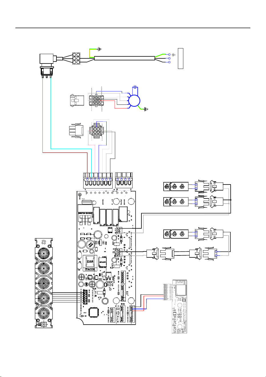
WIRINGDIAGRAM
0 1 2 3 4 5 6 7 8 9
H90_1144
01
Drawing N : Rev :
Modif. by
These drawings and specifications are the property of Franke Technology and
Trademartk Ltd and shall not be reproduced.copied or trasferred to any third party
without the prior written permission of Franke Tecnology and Trandemark Ltd.
Switzerland.It is strictly prohibited to get quotes from the drawing or bring
modifications without the prior written conset of franke Techology and Trademark
Doc.status
Modification description
Approved date
WIRING DIAGR.M8-4V CHA LED WI-FI STS/EXTERNAL
Approved by
Denomination
Doc Type
Creation date
14/10/2024
FABER Corrado
Created by
991.0724.314
Code
USER INTERFACE
CHL
PIN 3
PIN 1
PIN 3
PIN 1
PIN 9
PIN 7
PIN 9
PIN 7
1 2
LED BAR
1 2
1
2
3
4
5
6
7
1
2
3
4
L N
110-127V 60HZ
21
21
21
21
1 2
LED BAR
1 2
1 2
LED BAR
1 2
BRW
L-B
PNK
BLU
WHT
GRY
BLK
RED
M8-4V
BRW
ORG
BLK
GRY
WHT
BLU
BLK
GRY
BLK
GRY
BLU
RED
BLK
BLK
GRY
GRY
BLK

36
WARRANTY
Franke Home Solutions Warranty for Franke and Faber Branded Product
Effective March 1, 2022
In the United States, Canada and Latin America, Franke warrants the Faber branded products from manufacturing defects
in material and workmanship when purchased from a Franke or Faber Authorized Retailer pursuant to product-specific
warranties detailed herein (each, a “Warranty” and collectively, the “Warranties”). The products must be properly installed,
per Franke’s installation instructions, in their original installation, and used in normal indoor residential kitchen
applications. Any products or components which have been modified or altered from their original intended condition will
void the Warranty. The Franke Warranties for Faber branded products are limited to the original purchaser and are non-
transferrable. These Warranties do not include products purchased from non-Authorized Retailers, products that are
obsolete or discontinued, or products that were previous display models. All issues with installed products are considered
warranty claims and not subject to the Return Policy. Franke reserves the right to inspect any Franke / Faber product
reported to be defective pursuant to a Warranty claim and the original installation prior to providing a replacement product
and/or component. All decisions are final. In no situation shall the liability of Franke exceed the amount of the original
purchase price.
The Warranties do not cover, and Franke shall not be liable for, any damage to products or components resulting from
misuse or abuse, accidental damages, normal wear such as scuffs, scratches or finish reduction/fading, improper
installation, abnormal usage, negligence, damage caused by improper maintenance or cleaning. Damage caused by
impurities, corrosive chemicals or acts beyond Franke’s control are not covered by any Warranty. Service calls to correct
the installation of a range hood, instructions on how to operate a range hood, to replace or repair house fuses or to correct
house wiring or plumbing are not covered by any Warranty. Service calls to repair or replace range hood light bulbs, fuses
or filters and these consumable part costs are also excluded from Warranty coverage. Installation not in accordance with
electrical or plumbing codes or Franke / Faber documentation are not covered by any Warranty. Replacement parts or
repair labor costs for units operated outside the United States, Canada or Latin America, including any non-UL or C-UL or
non-NOM approved Franke / Faber range hoods are excluded from Warranty coverage. Expenses for travel and
transportation for service in remote locations and pickup and delivery charges are not covered by any Warranty. Franke /
Faber range hoods should always be serviced in the home in their original installation.
Franke / Faber product replacements do not include liability for project delays. Product replacements are not guaranteed
to be exact replacements. If the original product is not available at the time of the warranty claim, at Franke’s option, the
product replacements will be of similar size, material, and value. Any products or components which have been modified
or altered, from its original intended condition will void the warranty.
The Warranties do not allow recovery of incidental or consequential damages such as loss of use, delay, property
damage or other consequential damage, and Franke accepts no liability for such damages. Each Warranty is limited to
the conditions set forth herein and to the applicable warranty period specified herein and is exclusive. EXCEPT FOR THE
WARRANTIES SET FORTH HEREIN, FRANKE MAKES NO WARRANTY WHATSOEVER WITH RESPECT TO THE
PRODUCTS, INCLUDING, BUT NOT LIMITED TO, (1) ANY WARRANTY OF MERCHANTABILITY, (2) WARRANTY OF
FITNESS FOR A PARTICULAR PURPOSE, (3) WARRANTY OF TITLE, OR (4) WARRANTY AGAINST INFRINGEMENT
OF INTELLECTUAL PROPERTY RIGHTS OF A THIRD PARTY, WHETHER EXPRESS OR IMPLIED BY LAW, COURSE
OF DEALING, COURSE OF PERFORMANCE, USAGE OF TRADE OR OTHERWISE. LEGAL DISCLAIMER PLEASE
READ CAREFULLY. Franke Kitchen Systems LLC provides the above information to you as a public service to our
customers. By accessing and using this information, you agree to the following and to comply with all applicable laws. If
you do not agree with these terms and conditions, do not use this information. While we try to keep the information
current, changes may have occurred since its creation. Contact your Regional Manager or Customer Service to verify
information regarding Franke Kitchen Systems LLC programs and their use by you.
Franke / Faber Range Hood Limited Warranty:
Franke / Faber range hoods are warranted against any defect in materials or workmanship for the original purchaser for a
period of two (2) years from the date of original purchase when used in standard residential indoor applications. This
warranty covers labor and replacement parts. Franke, at its option, may repair or replace the product or components
necessary to restore the product to good working condition.
Franke Home Solutions Warranty for Franke and Faber Branded Product Effective March 1, 2022
In the United States, Canada and Latin America, Franke warrants the Faber branded products from manufacturing defects
in material and workmanship when purchased from a Franke or Faber Authorized Retailer pursuant to product-specific
warranties detailed herein (each, a “Warranty” and collectively, the “Warranties”). The products must be properly installed, per
Franke’s installation instructions, in their original installation, and used in normal indoor residential kitchen applications. Any
products or components which have been modified or altered from their original intended condition will void the Warranty.
The Franke Warranties for Faber branded products are limited to the original purchaser and are non- transferrable. These
Warranties do not include products purchased from non-Authorized Retailers, products that are obsolete or discontinued, or
products that were previous display models. All issues with installed products are considered warranty claims and not subject
to the Return Policy. Franke reserves the right to inspect any Franke / Faber product reported to be defective pursuant to a
Warranty claim and the original installation prior to providing a replacement product and/or component. All decisions are final.
In no situation shall the liability of Franke exceed the amount of the original purchase price.
The Warranties do not cover, and Franke shall not be liable for, any damage to products or components resulting from misuse
or abuse, accidental damages, normal wear such as scuffs, scratches or finish reduction/fading, improper installation, abnormal
usage, negligence, damage caused by improper maintenance or cleaning. Damage caused by impurities, corrosive chemicals
or acts beyond Franke’s control are not covered by any Warranty. Service calls to correct the installation of a range hood,
instructions on how to operate a range hood, to replace or repair house fuses or to correct house wiring or plumbing are not
covered by any Warranty. Service calls to repair or replace range hood light bulbs, fuses or filters and these consumable part
costs are also excluded from Warranty coverage. Installation not in accordance with electrical or plumbing codes or Franke
/ Faber documentation are not covered by any Warranty. Replacement parts or repair labor costs for units operated outside
the United States, Canada or Latin America, including any non-UL or C-UL or non-NOM approved Franke / Faber range hoods
are excluded from Warranty coverage. Expenses for travel and transportation for service in remote locations and pickup and
delivery charges are not covered by any Warranty. Franke / Faber range hoods should always be serviced in the home in their
original installation.
Franke / Faber product replacements do not include liability for project delays. Product replacements are not guaranteed to
be exact replacements. If the original product is not available at the time of the warranty claim, at Franke’s option, the product
replacements will be of similar size, material, and value. Any products or components which have been modified or altered,
from its original intended condition will void the warranty.
The Warranties do not allow recovery of incidental or consequential damages such as loss of use, delay, property damage or
other consequential damage, and Franke accepts no liability for such damages. Each Warranty is limited to the conditions set
forth herein and to the applicable warranty period specified herein and is exclusive. EXCEPT FOR THE WARRANTIES SET
FORTH HEREIN, FRANKE MAKES NO WARRANTY WHATSOEVER WITH RESPECT TO THE PRODUCTS, INCLUDING, BUT
NOT LIMITED TO, (1) ANY WARRANTY OF MERCHANTABILITY, (2) WARRANTY OF FITNESS FOR A PARTICULAR PURPOSE,
(3) WARRANTY OF TITLE, OR (4) WARRANTY AGAINST INFRINGEMENT OF INTELLECTUAL PROPERTY RIGHTS OF A
THIRD PARTY, WHETHER EXPRESS OR IMPLIED BY LAW, COURSE OF DEALING, COURSE OF PERFORMANCE, USAGE OF
TRADE OR OTHERWISE. LEGAL DISCLAIMER PLEASE
READ CAREFULLY. Franke Kitchen Systems LLC provides the above information to you as a public service to our customers.
By accessing and using this information, you agree to the following and to comply with all applicable laws. If you do not agree
with these terms and conditions, do not use this information. While we try to keep the information current, changes may have
occurred since its creation. Contact your Regional Manager or Customer Service to verify information regarding Franke Kitchen
Systems LLC programs and their use by you.
Franke / Faber Range Hood Limited Warranty:
Franke / Faber range hoods are warranted against any defect in materials or workmanship for the original purchaser for a
period of two (2) years from the date of original purchase when used in standard residential indoor applications. This warranty
covers labor and replacement parts. Franke, at its option, may repair or replace the product or components necessary to
restore the product to good working condition.

37
Franke Home Solutions Warranty for Franke and Faber Branded Product
Effective March 1, 2022
In the United States, Canada and Latin America, Franke warrants the Faber branded products from manufacturing defects
in material and workmanship when purchased from a Franke or Faber Authorized Retailer pursuant to product-specific
warranties detailed herein (each, a “Warranty” and collectively, the “Warranties”). The products must be properly installed,
per Franke’s installation instructions, in their original installation, and used in normal indoor residential kitchen
applications. Any products or components which have been modified or altered from their original intended condition will
void the Warranty. The Franke Warranties for Faber branded products are limited to the original purchaser and are non-
transferrable. These Warranties do not include products purchased from non-Authorized Retailers, products that are
obsolete or discontinued, or products that were previous display models. All issues with installed products are considered
warranty claims and not subject to the Return Policy. Franke reserves the right to inspect any Franke / Faber product
reported to be defective pursuant to a Warranty claim and the original installation prior to providing a replacement product
and/or component. All decisions are final. In no situation shall the liability of Franke exceed the amount of the original
purchase price.
The Warranties do not cover, and Franke shall not be liable for, any damage to products or components resulting from
misuse or abuse, accidental damages, normal wear such as scuffs, scratches or finish reduction/fading, improper
installation, abnormal usage, negligence, damage caused by improper maintenance or cleaning. Damage caused by
impurities, corrosive chemicals or acts beyond Franke’s control are not covered by any Warranty. Service calls to correct
the installation of a range hood, instructions on how to operate a range hood, to replace or repair house fuses or to correct
house wiring or plumbing are not covered by any Warranty. Service calls to repair or replace range hood light bulbs, fuses
or filters and these consumable part costs are also excluded from Warranty coverage. Installation not in accordance with
electrical or plumbing codes or Franke / Faber documentation are not covered by any Warranty. Replacement parts or
repair labor costs for units operated outside the United States, Canada or Latin America, including any non-UL or C-UL or
non-NOM approved Franke / Faber range hoods are excluded from Warranty coverage. Expenses for travel and
transportation for service in remote locations and pickup and delivery charges are not covered by any Warranty. Franke /
Faber range hoods should always be serviced in the home in their original installation.
Franke / Faber product replacements do not include liability for project delays. Product replacements are not guaranteed
to be exact replacements. If the original product is not available at the time of the warranty claim, at Franke’s option, the
product replacements will be of similar size, material, and value. Any products or components which have been modified
or altered, from its original intended condition will void the warranty.
The Warranties do not allow recovery of incidental or consequential damages such as loss of use, delay, property
damage or other consequential damage, and Franke accepts no liability for such damages. Each Warranty is limited to
the conditions set forth herein and to the applicable warranty period specified herein and is exclusive. EXCEPT FOR THE
WARRANTIES SET FORTH HEREIN, FRANKE MAKES NO WARRANTY WHATSOEVER WITH RESPECT TO THE
PRODUCTS, INCLUDING, BUT NOT LIMITED TO, (1) ANY WARRANTY OF MERCHANTABILITY, (2) WARRANTY OF
FITNESS FOR A PARTICULAR PURPOSE, (3) WARRANTY OF TITLE, OR (4) WARRANTY AGAINST INFRINGEMENT
OF INTELLECTUAL PROPERTY RIGHTS OF A THIRD PARTY, WHETHER EXPRESS OR IMPLIED BY LAW, COURSE
OF DEALING, COURSE OF PERFORMANCE, USAGE OF TRADE OR OTHERWISE. LEGAL DISCLAIMER PLEASE
READ CAREFULLY. Franke Kitchen Systems LLC provides the above information to you as a public service to our
customers. By accessing and using this information, you agree to the following and to comply with all applicable laws. If
you do not agree with these terms and conditions, do not use this information. While we try to keep the information
current, changes may have occurred since its creation. Contact your Regional Manager or Customer Service to verify
information regarding Franke Kitchen Systems LLC programs and their use by you.
Franke / Faber Range Hood Limited Warranty:
Franke / Faber range hoods are warranted against any defect in materials or workmanship for the original purchaser for a
period of two (2) years from the date of original purchase when used in standard residential indoor applications. This
warranty covers labor and replacement parts. Franke, at its option, may repair or replace the product or components
necessary to restore the product to good working condition.
This warranty supersedes all other warranties, expressed or implied. No employee, field sales
representatives, or distribution persons are authorized to give any warranties on behalf of Franke Kitchen
Systems, LLC
To make an installed product warranty claim please contact Franke at the provided contact information
below. All warranty claims must include the following for processing:
1. Proof of purchase from Franke or Faber Authorized Retailer
2. Original purchaser’s name, address (included city, state, zip), email address and phone number
3. Franke / Faber model and serial number
4. Date of installation
5. Description of the defect
6. Photos of the defect
In North America and Latin America:
Franke Home Solutions
Attn: Warranty Department
800 Aviation Parkway
Smyrna, TN 37167
HS-Warranty.US@Franke.com
Legal Entity:
Franke Kitchen Systems LLC

38
CONTENU
Section Page
Consignes de sécurité importantes
39
Dimensions de la hotte
44
Exigences en matière de hauteur d'installation
45
Pièces
46
Outils nécessaires
48
Préparation de l’installation de la hotte au plafond
49
Informations sur l'installation
51
Installation du corps de la hotte
52
Instruction de montage du plafond
54
Raccordements électriques
61
Utilisation des commandes
64
Application Faber Cloud
68
Télécommande
69
Nettoyage de l'acier inoxydable
69
Entretien
70
Remplacement de l'éclairage
71
Schéma de câblage
72
Garantie
73

39
CONSIGNESDESÉCURITÉIMPORTANTES
VEUILLEZ LIRE ET CONSERVER LA PRÉSENTE NOTICE
AVANT DE COMMENCER L'INSTALLATION DE LA HOTTE DE
CUISINE
AVERTISSEMENT: - POUR RÉDUIRE LE RISQUE D'UN FEU DE GRAISSE SUR LA
TABLE DE CUISSON:
a) Ne laissez jamais sans surveillance les éléments de la surface de cuisson à
température élevée. Les bouillonnements excessifs peuvent provoquer de la
fumée et les débordements de graisse peuvent s'enflammer. L'huile doit être
chauffée lentement, à une température basse ou moyenne.
b) Assurez-vous de toujours mettre en marche la hotte lorsque vous cuisinez à
température élevée ou préparez un mets flambé (p.ex. crêpes Suzette, cerises
jubilé, bœuf flambé).
c) Nettoyez régulièrement les ventilateurs d'aspiration. Assurez-vous de ne pas
laisser de la graisse s'accumuler sur le ventilateur ou le filtre.
d) Utilisez toujours des poêles et casseroles de la taille appropriée. Utilisez toujours
des ustensiles de cuisine de la taille adaptée à celle de l'élément chauffant.
AVERTISSEMENT: - POUR PRÉVENIR LES BLESSURES EN CAS DE FEU DE GRAISSE
SUR LA TABLE DE CUISSON, SUIVEZ LES RECOMMANDATIONS SUIVANTES*:
a) ÉTOUFFEZ LES FLAMMES à l'aide d'un couvercle hermétique, d'une plaque à
biscuits ou d'un plateau métallique, puis éteignez le brûleur. FAITES ATTENTION
AUX BRÛLURES. Si le feu ne s'éteint pas immédiatement, QUITTEZ LES LIEUX
ET APPELEZ LES POMPIERS.
b) NE PRENEZ JAMAIS UNE CASSEROLE EN FLAMME - Vous pourriez vous brûler.
c) N'UTILISEZ JAMAIS DE L'EAU, ni un linge à vaisselle ou un torchon mouillé,
pour éteindre le feu. Cela pourrait provoquer une violente explosion de vapeur.
d) Utilisez un extincteur UNIQUEMENT si:
1. Vous êtes certain qu'il s'agit d'un extincteur de classe ABC et que vous connaissez
bien son mode d'emploi.
2. Le feu est de faible intensité et se limite à l'endroit où il a démarré.
3. Les pompiers ont déjà été appelés.
4. Une voie de sortie se trouve derrière vous pendant que vous éteignez les
flammes.
* D'après le guide «Kitchen Firesafety Tips» publié par la NFPA aux États-Unis
AVERTISSEMENT - POUR RÉDUIRE LE RISQUE D'INCENDIE OU DE CHOC
ÉLECTRIQUE, n'utilisez jamais ce ventilateur en association avec un dispositif de
réglage de vitesse à semi-conducteurs.
AVERTISSEMENT - POUR RÉDUIRE LES RISQUES D'INCENDIE, DE CHOC
ÉLECTRIQUE OU DE BLESSURE CORPORELLE, RESPECTEZ LES INSTRUCTIONS
SUIVANTES:
1. Utilisez cet appareil uniquement de la façon prévue par le fabricant. Pour toute
question, communiquez avec le fabricant.
2. Avant de procéder à l'entretien ou au nettoyage de l'appareil, coupez
l'alimentation au niveau du panneau électrique et verrouillez-le pour vous
assurer que l'électricité n'est pas rétablie accidentellement. S'il n'est pas
possible de verrouiller le dispositif d'interruption de l'alimentation, affichez
de façon ferme et bien visible un avis de danger, par exemple à l'aide d'une
étiquette sur le panneau.
ATTENTION: Destiné à un usage de ventilation générale uniquement. N'utilisez pas

40
ce dispositif pour l'aspiration de vapeurs ou de matériaux dangereux ou explosifs.
AVERTISSEMENT - POUR RÉDUIRE LES RISQUES D'INCENDIE, DE CHOC
ÉLECTRIQUE OU DE BLESSURE CORPORELLE, RESPECTEZ LES INSTRUCTIONS
SUIVANTES:
1. L'installation et le branchement électrique doivent être réalisés par un technicien
qualifié et conformément à tous les codes et normes en vigueur, incluant ceux
concernant la construction à l'épreuve du feu.
2. Afin de garantir une combustion et une évacuation adéquates des gaz par les
conduites de la cheminée des appareils à combustion, une bonne aération est
nécessaire pour éviter le refoulement. Respectez les lignes directrices fournies
par le fabricant du matériel chauffant, ainsi que les normes de sécurité comme
celles publiées par la National Fire Protection Association (NFPA) et la American
Society for Heating, Refrigeration and Air Conditioning Engineers (ASHRAE)
aux États-Unis, ainsi que les codes en vigueur dans votre région.
3. Lorsque vous faites une ouverture ou percez dans un mur ou le plafond, veillez
à ne pas endommager les fils électriques ou d'autres dispositifs cachés.
4. Les ventilateurs à conduit doivent toujours être évacués vers l'extérieur.
TOUTE OUVERTURE DANS LE MUR OU LE PLANCHER À PROXIMITÉ DE LA
HOTTE DOIT ÊTRE SCELLÉE.
Un espace libre d'au moins 30" est requis entre le bas de la hotte et la surface de
cuisson ou le comptoir. Cette hotte a été homologuée par l'UL à cette distance de la
surface de cuisson.
Consultez la notice d'installation de la surface de cuisson ou de la cuisinière fournie par
le fabricant avant de pratiquer des ouvertures. INSTALLATION DANS UNE MAISON
MOBILE L'installation de cette hotte doit être conforme à la Partie 3280 de la norme
Manufactured Home Construction and Safety Standards, Title 24 CFR (précédemment
la partie 280 de la norme Federal Standard for Mobile Home Construction and Safety,
Title 24, HUD).
À noter: La présente hotte a été conçue pour réduire au minimum l’interférence électromagnétique
(EMI) provenant de l’alimentation électrique domestique. Il peut toutefois survenir que, dans
certaines applications domestiques, l’EMI ambiante et l’EMI excessive des autres dispositifs
électroniques puissent nuire au fonctionnement de la télécommande.
Renseignez-vous auprès de votre distributeur Faber au sujet d’une pièce de rechange en option
permettant de réduire l’EMI des sources domestiques.
CRITÈRES DE VENTILATION
Déterminez quelle méthode de ventilation est mieux adaptée à votre application. Les
conduits peuvent passer par le mur ou le toit.
Pour garantir une meilleure efficacité, la longueur des conduits et le nombre de coudes
doivent être le plus limités que possible. Le diamètre des conduits devrait être uniforme.
N'installez pas deux coudes ensemble. Utilisez un ruban pour canalisations afin de
sceller tous les joints du système de conduits. Utilisez un calfeutrage pour sceller les
ouvertures dans le mur extérieur ou le plafond, autour du clapet.
Il n'est pas recommandé d'utiliser des conduits flexibles. Les conduits flexibles
provoquent une contre-pression et de la turbulence qui diminuent grandement
l'efficacité de l'appareil.
Assurez-vous que l'espace libre dans le mur ou le plafond est suffisant pour le conduit
d'évacuation avant de pratiquer les ouvertures. Ne coupez jamais une poutre ou un
chevron, sauf si c'est absolument nécessaire. S'il s'avère nécessaire de couper une
41
poutre ou un chevron, la construction d'un renforcement est requise.
AVERTISSEMENT - Pour réduire le risque d'incendie, utilisez uniquement des
conduits métalliques.
ATTENTION - Pour réduire le risque d'incendie et pour évacuer adéquatement
l'air, assurez-vous de raccorder les conduits à l'extérieur – Ne diffusez pas l'air
d'évacuation dans des espaces à l'intérieur des murs ou du plafond, ou encore à
l'intérieur d'un grenier, d'une galerie technique ou d'un garage.
AVERTISSEMENT : Pour réduire les risques d'incendie, d’électrochoc ou de blessure,
n'utilisez pas de pièces de rechange non préconisées par le fabricant (par exemple,
des pièces bricolées à la maison à l'aide d'une imprimante 3D).
Installation dans les climats froids
Le système de ventilation doit prévoir un registre antirefoulement supplémentaire pour réduire le
flux d'air froid inverse, ainsi qu'une barrière thermique non métallique pour réduire la conduction
des températures extérieures. Le registre doit être installé du côté air froid par rapport à la barrière
thermique. La barrière thermique doit être positionnée le plus près que possible de l'endroit où
le système de ventilation pénètre dans la partie chauffée de la maison.
•
Le système de ventilation DOIT déboucher à l'extérieur.
• NE FAITES PAS déboucher les conduits dans un grenier ou un autre
endroit fermé.
• N’UTILISEZ PAS un clapet de sécheuse mural de 4".
• Il n'est pas recommandé d'utiliser des conduits flexibles.
• N’ENTRAVEZ PAS le flux de l'air de combustion et de ventilation.
• Le non-respect des exigences en matière de ventilation pourrait entraîner
un incendie.
AVERTISSEMENT
!
42
• Une mise à la terre électrique est requise pour cette hotte.
• N'UTILISEZ PAS un tuyau d'eau froide pour la mise à la terre si celui-ci est
branché par des joints en plastique, par des rondelles non métalliques ou
d'autres matériaux.
• N'UTILISEZ PAS une conduite de gaz pour la mise à la terre.
• N'INSTALLEZ PAS un fusible sur le circuit neutre ou le circuit de mise à la
terre. La présence d'un fusible dans le circuit neutre ou de mise à la terre peut
entraîner un choc électrique.
• Consultez un électricien qualifié si vous n'êtes pas certain de la mise à la terre
de la hotte.
• Le non-respect des exigences de la fiche technique électrique pourrait
entraîner un incendie
.
AVERTISSEMENT
!
FICHE TECHNIQUE ÉLECTRIQUE
Une alimentation de courant alternatif de 120 volts à 60Hz est requise sur un circuit à
fusible distinct de 15 ampères. Il est recommandé d'installer un fusible temporisé ou un
disjoncteur. Le fusible doit être calibré conformément aux codes en vigueur pour les
caractéristiques nominales électriques de l'appareil, indiquées sur la plaque signalétique
située à l'intérieur de l'appareil, à proximité du compartiment des câblages externes.
INSTALLATION ÉLECTRIQUE AVEC BOÎTIER DE CONNEXION
CET APPAREIL DOIT ÊTRE UNIQUEMENT BRANCHÉ À L'AIDE DE FILS DE CUIVRE.
Le calibre des fils doit être conforme aux critères de la dernière édition du National
Electrical Code, de l'ANSI/NFPA 70 et de l'ensemble des codes et réglementations en
vigueur. Le calibre des fils et les connexions doivent être adaptés aux caractéristiques
nominales de l'appareil. Il est possible de se procurer un exemplaire des normes
indiquées ci-dessus en communiquant avec:
National Fire Protection Association
Batterymarch Park
Quincy, Massachusetts 02269 (États-Unis)
Cet appareil devrait être branché directement au sectionneur à fusible (ou au disjoncteur)
par un câble flexible de cuivre avec blindage ou gaine non métallique. Laissez un
peu de jeu dans le câble pour permettre le déplacement de l'appareil si des travaux
d'entretien s'avéraient nécessaires. Un raccord de conduit homologué par l'UL de 1/2"
doit être installé aux deux extrémités du câble d'alimentation (au niveau de l'appareil
et de la boîte de liaison).
Lors de la réalisation du branchement électrique, réalisez un trou de 11/4". S'il s'agit
d'un trou dans le bois, il doit être poncé pour le rendre lisse. S'il s'agit d'un trou dans
le métal, un passe-fils est requis.

43
ATTENTION:Lespiècesaccessiblespeuventdevenirchaudeslorsqu'ellessontutilisées
avecdesappareilsdecuisson.
•L'airnedoitpasêtreévacuédansunconduitdefuméeutilisépourévacuerlesfumées
desappareilsbrûlantdugazoud'autrescombustibles.
•SiunAPPAREILSTATIONNAIREn'estpaséquipéd'unCORDD'ALIMENTATIONet
d'uneche,oud'autresmoyensdedéconnexiondusecteurd'alimentationayant
uneséparationdescontactsdanstouslespôlesquipermettentunedéconnexion
complètedansdesconditionsdecatégoriedesurtensionlII,lesinstructionsdoivent
indiquerquedesmoyenspourladéconnexiondoitêtreintégréeaucâblagexe
conformémentauxrèglesdecâblage.
•Ladéconnexionpeutêtreréaliséeenrendantlacheaccessibleouenincorporant
uninterrupteurdanslecâblagexeconformémentauxrèglesdecâblage.
•Cetappareiln'estpasdestinéàêtreutilisépardespersonnes(ycomprisdesenfants)
dontlescapacitésphysiques,sensoriellesoumentalessontdifférentesouréduites,
ouquimanquentd'expérienceoudeconnaissances,àmoinsquecespersonnesne
soientsuperviséesouforméespourlefonctionnementdel'appareilparunepersonne
responsabledeleursécurité.
•Lesenfantsdoiventêtresurveilléspours'assurerqu'ilsn'utilisentpaslesappareils
comme un jouet.
•Neambezpasd'alimentssouslahotte.
•l'airnedoitpasêtreévacuédansunconduitdefuméeutilisépourévacuerlesfumées
d'appareilsbrûlantdugazoud'autrescombustibles(nes'appliquepasauxappareils
quirejettentuniquementl'airdanslapièce);
•ildoityavoiruneventilationadéquatedelapiècelorsquelahottedecuisineest
utiliséeenmêmetempsquedesappareilsbrûlantdugazoud'autrescombustibles
(nes'appliquepasauxappareilsquirejettentuniquementl'airdanslapièce);
•ilexisteunrisqued'incendiesilenettoyagen'estpaseffectuéconformémentaux
instructions;
•Cetappareildoitêtremisàlaterre.Encasdecourt-circuitélectrique,lamiseàla
terreréduitlerisquedechocélectriqueenfournissantunldefuitepourlecourant
électrique.Cetappareilestéquipéd'uncordondotéd'unldeterreavecuneche
demiseàlaterre.Lachedoitêtrebranchéedansuneprisecorrectementinstallée
etmiseàlaterre.
AVERTISSEMENT-unemiseàlaterreincorrectepeutentraînerunrisquedechoc
électrique.
•Consultezunélectricienqualiésilesinstructionsdemiseàlaterrenesontpas
entièrement comprises ou s'il existe des doutes quant à savoir si l'appareil est
correctementmisàlaterre.

44
17-Oct-2024
Released
DIMENSIONSDELAHOTTE

45
EXIGENCESENMATIÈREDEHAUTEUR
D'INSTALLATION
Pour de meilleures performances, veuillez monter la hotte à 30pouces au-dessus de
la surface de cuisson, mais vous pouvez la monter jusqu'à 72pouces maximum de la
surface de cuisson.
Veuillez prévoir un point d'accès à la hotte depuis le plafond ou le soffite pour
l'installation et l'accès futur à la hotte.
MIN. 30POUCES AU-DESSUS DES
RACCORDEMENTS D’ÉLECTRICITÉ / DU GAZ
Installation non canalisée
Cette hotte est conçue pour être montée au plafond et uniquement en mode
Recirculation.
Trois personnes sont nécessaires pour
installer la hotte
Portez des gants de protection pour le
travail
MAX. 72POUCES AU-DESSUS DES
RACCORDEMENTS D’ÉLECTRICITÉ / DU GAZ

46
PIÈCES
PIÈCES INCLUSES
RÉF. PIÈCE QTÉ
A
Corps de la hotte, équipé de: Commandes, éclairages, filtres. 1
E
Télécommande 1
H
Gabarit de perçage 1
L
Support de plafond 2
I
Câble pour plafond 4
RÉF
PIÈCE
QTÉ
C
Vis 4/16" x 2-12/16" 8
O
Butée transparente 1
O1
Butée 1
P
Vis 2/16" x 4/16" 2
R1
Cache d’extrémité 1
W
Filtre à charbon 2

47
8
AA-725973-1
1x
1x
C
1x
B
A
1x
3x 4x
1x
D E
1x
1x
1x
1x
H
O
I
A
E
L
W
R1
O1

48
PIÈCESNÉCESSAIRES
PIÈCES(suite)
PIÈCE
Connecteurs de fils.
OUTILSNÉCESSAIRES
OUTIL
Mètre ruban
Crayon
Perceuse électrique avec mèche de 5/16 pouces
Tournevis Phillips
Gants de travail
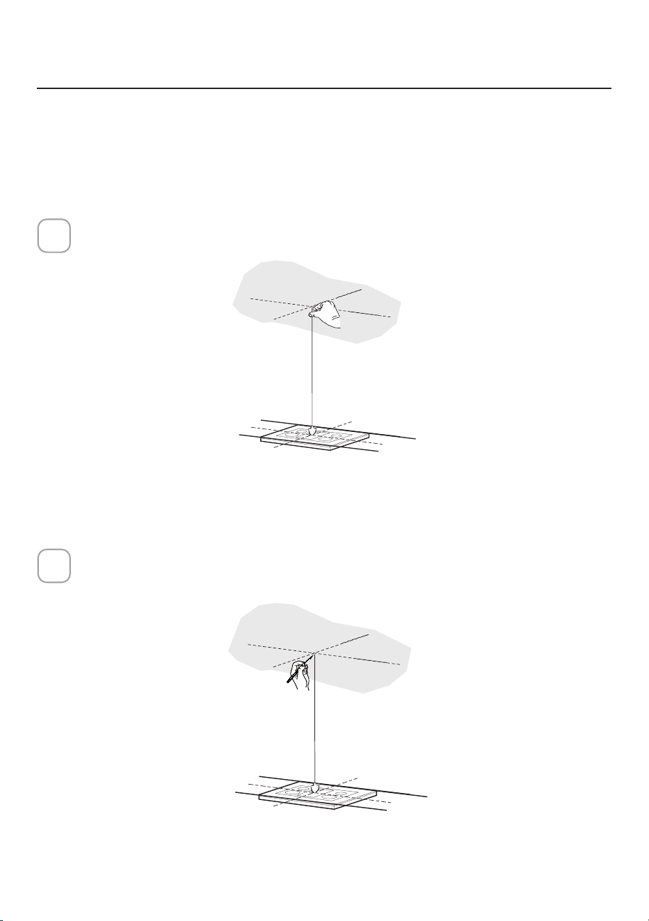
49
Utilisez un fil à plomb pour marquer le centre de la cuisinière au plafond.
1
PRÉPARATIONDEL'INSTALLATIONDELAHOTTE
AUPLAFOND
Marquer le centre.
2
Ne faites aucune découpe avant d'avoir décidé si l'installation sera non canalisée
et si le câblage a été préparé en fonction du type de soufflante.
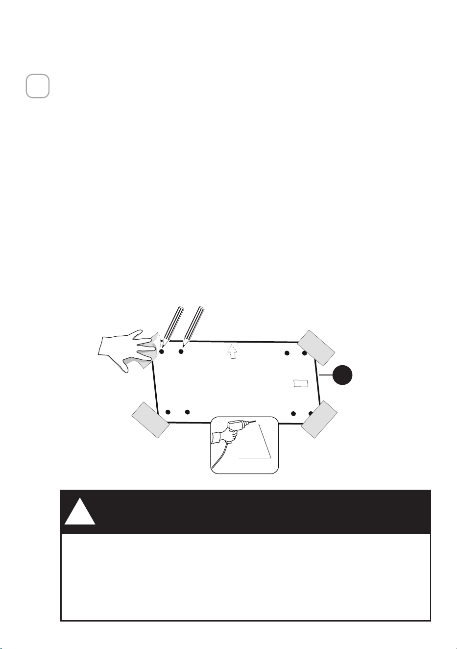
50
H
3/8"
EN RAISON DE LA TAILLE ET DU POIDS DE CETTE HOTTE DE
CUISINE, LE SUPPORT DOIT ÊTRE FIXÉ FERMEMENT AU PLAFOND.
Si vos plafonds sont en plâtre ou en placoplâtre, veuillez fixer les
supports aux solives. Si cela n'est pas possible, une structure de
support doit être construite derrière le plâtre ou le placoplâtre. Le
fabricant n'assume aucune responsabilité pour les blessures ou les
dommages causés par des installations inadéquates.
AVERTISSEMENT
!
• Mettez un revêtement épais et protecteur sur la table de cuisson pour la
protéger des dommages ou de la saleté.
• Utilisez le gabarit de montage au plafond pour déterminer l'emplacement
des vis de montage au plafond.
• Marquez le centre des trous dans le gabarit du plafond.
• Repérez l'emplacement approprié pour le câble d'alimentation, comme
indiqué sur le gabarit.
• Utilisez un foret de 3/8" pour percer ce trou.
• Faites passer le câble d'alimentation. Utilisez un produit de calfeutrage
pour sceller le trou.
• Un alvéole défonçable pour le passage du câble d'alimentation depuis le
plafond se situe sur le dessus de la hotte.
• Ne connectez pas le câble d'alimentation à la boîte de câblage et ne mettez
pas la hotte sous tension pour le moment.
• Faites passer suffisamment de câble d'alimentation depuis le plafond pour
atteindre la boîte de câblage sur la hotte.
3

51
OK!
3/16"
OK!
3/16"
OK!
3/16
"
C
INFORMATIONSSURL'INSTALLATION
Pour la préparation de l'installation de la hotte, orientez la hotte avec le panneau
de commande à l'avant de la hotte, comme indiqué ci-dessous.
CORRECT
PAS
CORRECT
Utilisez uniquement des vis et des petites pièces servant à supporter la hotte.
Avertissement: Le fait de ne pas installer les vis conformément à ces instructions
peut entraîner des risques électriques.
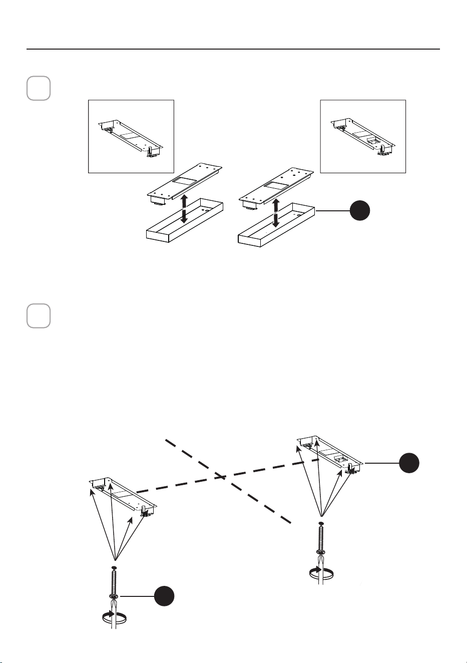
52
INSTALLATIONDUCORPSDELAHOTTE
Retirez le couvercle des supports pour plafond (L).
4
Installation au plafond
Utilisez les trous créés avec le gabarit de perçage pour localiser les fixations
au plafond.
Utilisez un foret de 5/16" pour percer ces trous.
Utilisez des chevilles si nécessaire ou d'autres éléments de fixation en
conjonction avec les fixations au plafond (achetées séparément).
Fixez les supports au plafond (L) avec les 8 vis (C) dans les supports jusqu’à
ce qu’ils soient serrés et solidement fixés.
5
DX
SX
L= 4X
L= 4X
C
L
Gauche
Droite
I = 8X
8X
Ø10mm
DXSX
DX
L
Gauche Droite
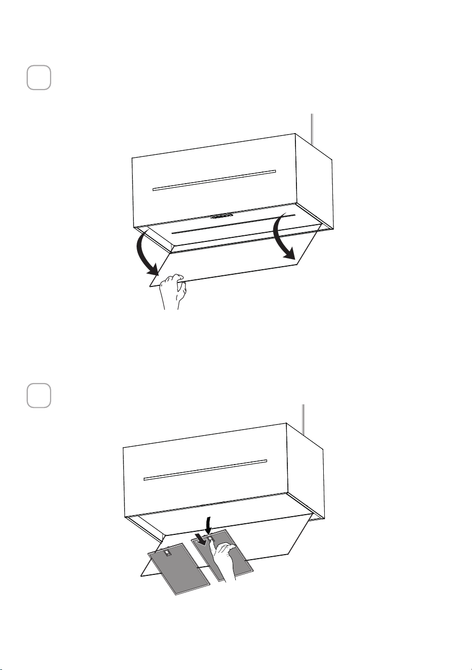
53
Ouvrez le cache du filtre.
Ce panneau est retenu par un aimant, tirez vers le bas avec suffisamment de
force pour le libérer comme indiqué ci-dessous.
6
Retirez les filtres à graisse.
7
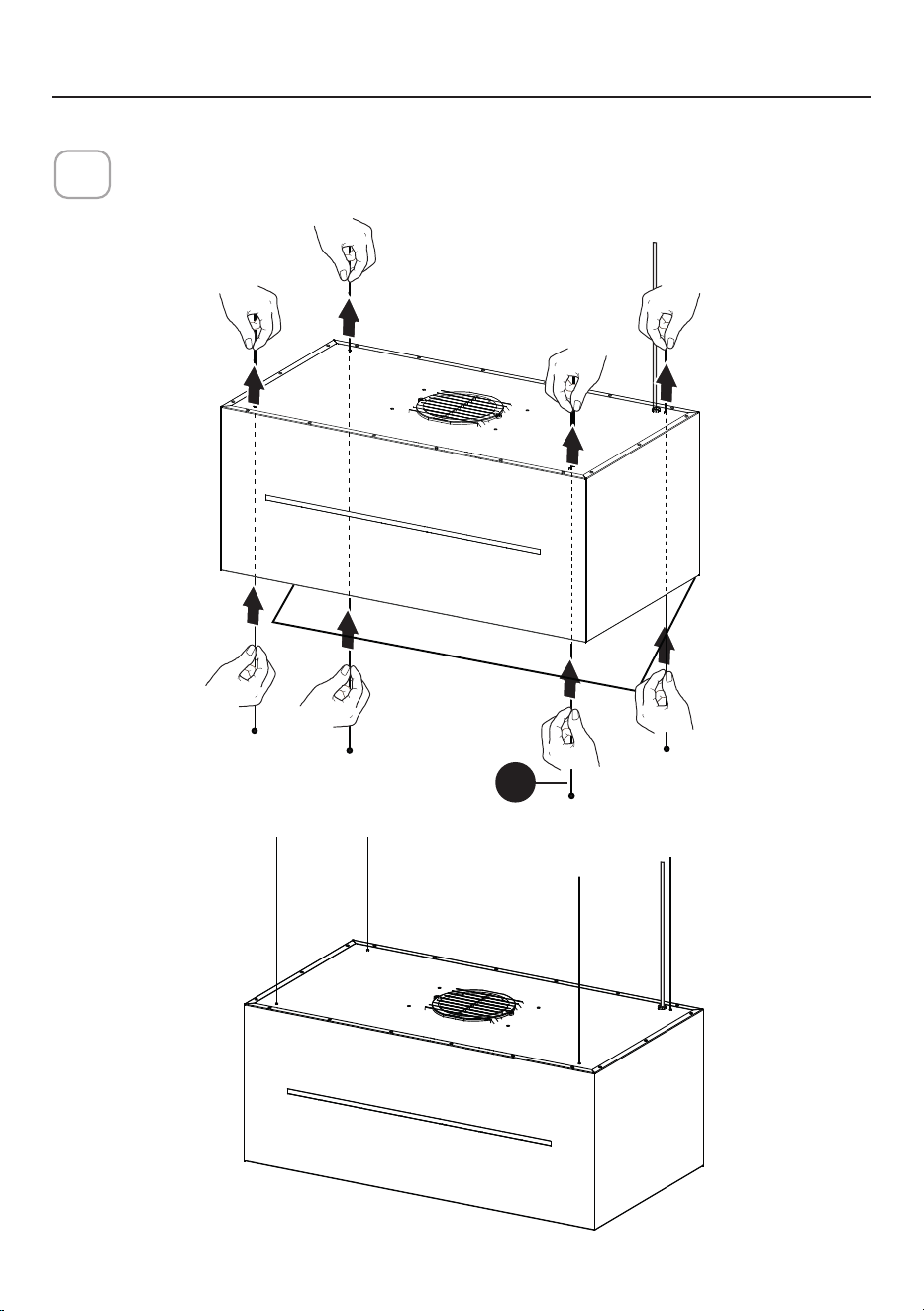
54
I
Insérez les câbles de plafond (I) en les faisant passer par le fond de la hotte
et ressortir par le haut de celle-ci.
8
INSTRUCTIONDEMONTAGEDUPLAFOND
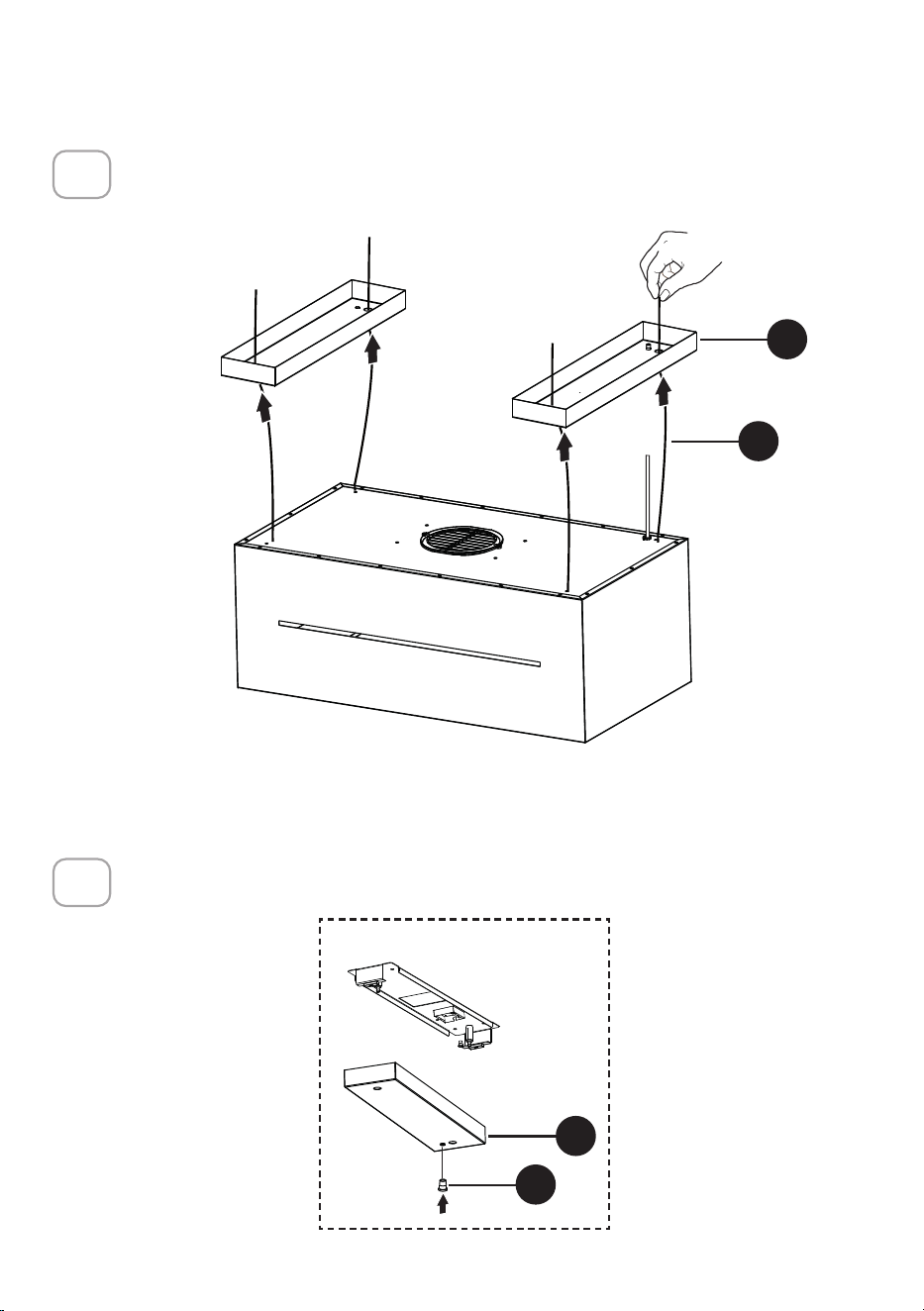
55
4x
DXSX
I
L
Faites passer les câbles (I) dans les quatre trous des couvercles des suppor-
ts de plafond (L).
9
Insérer le bouchon transparent (O) dans le couvercle droit des supports de
plafond (L).
10
DXSX
O
L
DX
Droite

56
Insérez dans le couvercle du support de plafond droit (L) le Câble d’alimen-
tation électrique.
11
L
I = 8X
8X
Ø10mm
DX
SX
DX
Droite
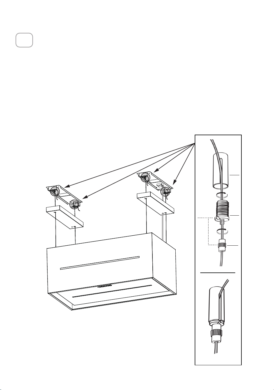
57
4x
A1
B1
C1
D1
4x
RACCORDEMENT DES CÂBLES ENTRE HOTTE ET PLAQUES
ATTENTION! Avant de poursuivre l'installation, il est nécessaire de déplacer
la hotte à une hauteur d’au moins 75cm (30 po) du plan de cuisson électrique
et du plan de cuisson au gaz, en utilisant un support ou l'aide d'une autre
personne.
Cette opération est indispensable, car les câbles de la hotte doivent
impérativement être raccordés à la plaque fixée au plafond, sans que le poids
de la hotte ne pèse sur la structure.
Le système de fixation des câbles est composé de 3 parties:
• Cliquets filetés (A1) déjà montés aux supports de plafond.
• Vis de serre-câble (B1) fournies (D1).
• Molettes de sécurité (C1) fournies (D1).
12

58
B1
C1
15.1 15.2 15.3
A1
B1
RACCORDEMENT DES CÂBLES ENTRE HOTTE ET PLAQUES
FIXATION DU CORPS DE LA HOTTE
• Introduisez les câbles dans les molettes de sécurité (C1) avec un filetage
en haut (Fig. 15.1).
• Faites passer les câbles dans les vis de serre-câble(
B1
) (Fig. 15.1).
• Faites passer les câbles dans les fentes jusque dans les cliquets filetés (
A1
)
et vissez les vis de blocage des câbles (
B1
) aux cliquets eux-mêmes (Fig.
15.2).
• Une fois l’opération terminée, le résultat doit être conforme à la figure pour
les 4 câbles (Fig. 15.3).
• À ce stade, les 4 câbles sont reliés aux supports de plafond.
Mettez les câbles sous tension en les poussant vers le haut de manière à ce
qu’ils glissent à l’intérieur de la vis du serre-câble et sortent de la fente du
cliquet fileté.
Cela est possible parce que la vis du serre-câble possède un système qui, s’il
est correctement monté, permet aux câbles de glisser à l’intérieur dans un seul
sens et l’empêche de glisser dans l’autre sens.
Attention, les câbles ont tous la même longueur pour faciliter les opérations de
mise à niveau finale. Le câble avant gauche ne doit pas être plus lâche que les
autres.
13
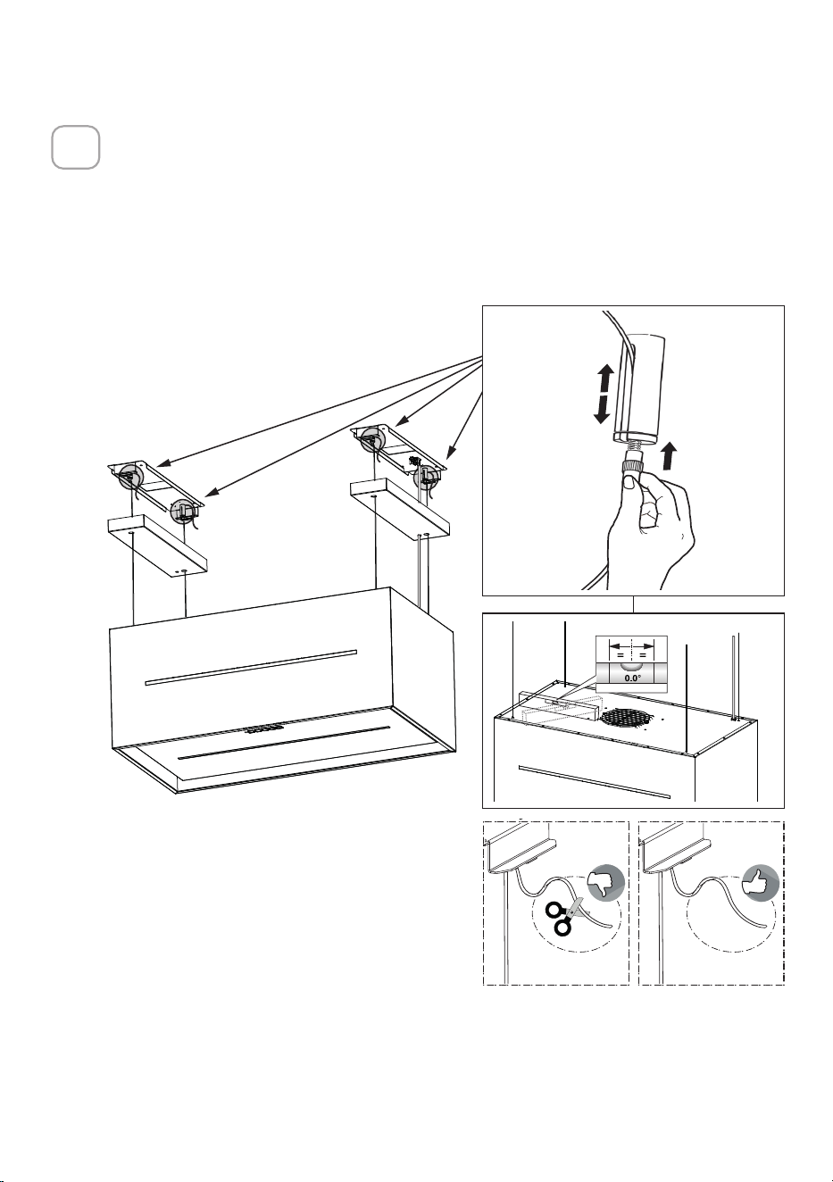
59
4x
1
2
1
2
4x
MISE À NIVEAU DE LA HOTTE
• La hotte est mise à niveau en ajustant les cliquets de sécurité.
• Placez un niveau à bulle sur la hotte.
• Quand les molettes de sécurité sont pressées vers le haut, le
mouvement de la hotte est «débloqué». En insérant ou en extrayant le
câble de la vis du serre-câble, il est possible d’effectuer des réglages qui
permettent de mettre à niveau le corps de la hotte mobile.
• Une fois la hotte mise à niveau, resserrez les molettes de sécurité.
14
Avertissement:
• Vérifiez que les 4 câbles sont tendus.
• Vérifiez que les 4 câbles n’ont pas été endommagés pendant
l’installation.
• NE coupez PAS la partie excessive des câbles.
• Il convient de rappeler que la distance minimum entre la hotte et le
plan de cuisson à gaz ou électrique doit être d’environ 30".

60
W
INSTALLATION DES FILTRES À CHARBON
Recirculation non canalisée uniquement
• Ouvrez l’unité d’éclairage en tirant sur l’encoche prévue à cet effet.
• Retirez les filtres à graisse.
• Vérifiez que les filtres au charbon actif ont été installés.
• Voir aussi le paragraphe «Entretien».
15

61
Version 02/12 - Page 8
FIGURE 13
MAKE THE ELECTRICAL CONNECTION
Remove the cover from the eld wiring compartment. (SEE
FIGURE 11) DO NOT turn on the power until installation is
complete! Connect the Power Supply Cable to the rangehood.
Connect the Green (Green and Yellow) ground wire under the
Green grounding screw. Attach the White lead of the power
supply to the White lead of the rangehood with a twist-on type
wire connector. Attach the Black lead of the power supply
to the Black lead of the rangehood with a twist-on type wire
connector.
1. The UPPER CHIMNEY
COVER (C in FIGURE 13)
attaches to the top of the
support structure using two
screws provided (G in FIGURE
13). If using the High Ceiling
Chimney Kit, use the UPPER
CHIMNEY COVER supplied
with the kit. Slide up and
attach the UPPER CHIMNEY
COVER.
2. Attach the duct work to the
DAMPER (M in FIGURE 1).
Make sure to seal all joints with
duct tape to prevent leaks.
3. The LOWER CHIMNEY
COVER (B in FIGURE 13)
attaches using two screws
provided (G in FIGURE 13).
Install the LOWER CHIMNEY
COVER by sliding it up over
the support and the UPPER
CHIMNEY COVER.
For ductless installations, line up the DUCTLESS DIVERTER
EXTENSIONS HORIZONTAL (B in FIGURE 12) with the holes
in the LOWER CHIMNEY COVER (D in FIGURE 12) and snap
in the VENT GRIDS (C in FIGURE 12).
INSTALLING THE RANGEHOOD
A. Home power supply cable
B. Black wires
C. UL listed wire connectors
D.White wires
E. Green (or bare) ground wire from home power supply
connected to green ground screw
F. Range hood power supply cable
G.Range hood power supply cable connected to green
ground screw
FIGURE 11
Ductless installations require
a Ductless Conversion
Kit whose components are
pictured in FIGURE 12. Do
not use the DAMPER (M
in FIGURE 1) for ductless
installations. The LOWER
CHIMNEY COVER ( B
in FIGURE 1) should be
discarded and replaced by
the new one with holes from
the Ductless Conversion Kit
(D in FIGURE 12).
As indicated in FIGURE
12, place the DUCTLESS
DIVERTER (A) over the
exhaust opening of the EASY
CUBE (E). Fit the DUCTLESS
DIVERTER EXTENSIONS
HORIZONTAL (B) into the
DIVERTER (A).
FIGURE 12
FOR DUCTLESS INSTALLATIONS
RACCORDEMENTSÉLECTRIQUES
Installation de la connexion du câblage
Retirez le couvercle du compartiment de câblage de terrain.
NE mettez PAS l'appareil sous tension tant que l'installation n'est pas
terminée!
Connectez le câble d'alimentation à la hotte.
Connectez le fil de terre vert (vert et jaune) sous la vis de mise à la terre
verte. Fixez le fil blanc de l'alimentation au fil blanc de la hotte avec un
connecteur de type torsadé.
Fixez le fil noir de l'alimentation au fil noir de la hotte à l'aide d'un
connecteur de type torsadé.
Remettez en place le couvercle du compartiment de câblage de terrain et
les filtres à graisse.
16
A. Câble d'alimentation domestique
B. Fils noirs
C. Connecteurs de fils homologués UL
D. Fils blancs
E. Fil de terre vert (ou dénudé) de l'alimentation électrique de la maison
connecté à la vis de terre verte
F. Câble d'alimentation de la hotte
G. Câble d'alimentation de la hotte connecté à la vis de terre verte.
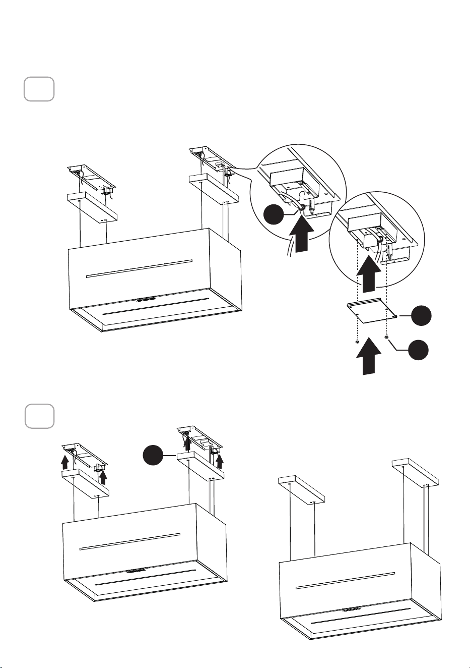
62
L
R1
P
O1
Enfilez le câble d’alimentation dans la butée (O1) et faites-le coulisser
complètement dans le raccord de câblage.
Fermez le raccord de câblage avec le cache d’extrémité (R1) et fixez-le à
l’aide de 2 vis (P).
17
Remettez en place le couvercle des supports de plafond (L).
18

63
Remplacez les filtres à graisse.
19
Fermez le panneau du couvercle du filtre.
20
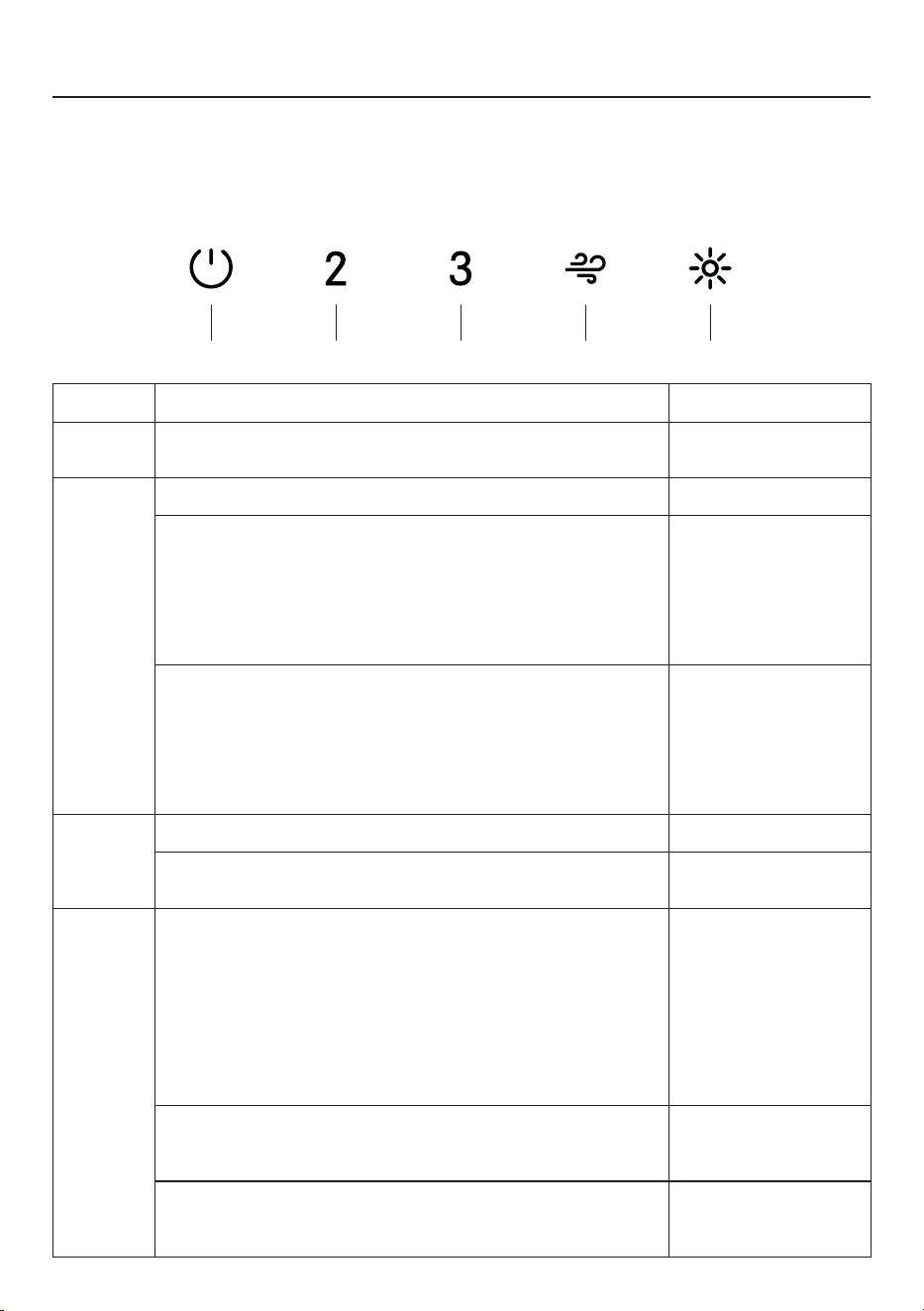
64
A CB D E
UTILISATION DES COMMANDES
POUR DE MEILLEURS RÉSULTATS
Mettez la hotte en marche plusieurs minutes avant la cuisson pour assurer une bonne
circulation de l'air. Laissez la hotte fonctionner pendant plusieurs minutes après la fin
de la cuisson pour évacuer la fumée et les odeurs de la cuisine.
BOUTON FONCTION LED
A
Mettez le moteur de marche/arrêt (on/off) à la première
vitesse.
Fixe.
B
Mettez le moteur en marche sur la deuxième vitesse. A et B fixes.
Appuyez de manière prolongée quand la lumière est
allumée:
Active/désactive l’alarme des filtres au charbon actif.
Toutes les Led
clignotent deux fois:
alarme activée.
Toutes les Led
clignotent une fois:
alarme désactivée.
Appuyez de manière prolongée quand toutes les charges
sont désactivées (Moteur+Lumière):
Active/désactive la fonction de Connexion au Wi-Fi.
Remarque: la fonction Wi-Fi est automatiquement
activée lorsque l’utilisateur demande la procédure de
configuration Wi-Fi.
Led E clignotante:
connexion au réseau
domestique en cours.
Led E fixe:
Connexion au Wi-Fi
activée.
C
Mettez le moteur en marche sur la troisième vitesse. A et C fixes.
Appuyez de manière prolongée quand le moteur est éteint:
L’alarme de saturation du filtre est réinitialisée.
Toutes les leds
clignotent 3 fois.
D
Mettez le moteur en marche sur la vitesse Intense.
Cette vitesse est programmée pour durer 6
minutes. Une fois ce temps écoulé, le système
retourne automatiquement à la vitesse sélectionnée
précédemment. S’il est activé quand le moteur est éteint,
une fois le temps écoulé, il passe en mode OFF.
Il est désactivé en appuyant sur le même bouton ou en
coupant le moteur.
Clignotant.
Signale l’alarme de filtres à graisse métalliques saturés
et qu’il est nécessaire de les laver. L’alarme est activée
après 100 heures de fonctionnement effectif de la hotte.
Leds B et D
clignotantes.
Signale l’alarme du filtre anti-odeur au charbon actif
saturé. L’alarme est activée après 200 heures de
fonctionnement effectif de la hotte.
Leds A et D
clignotantes.
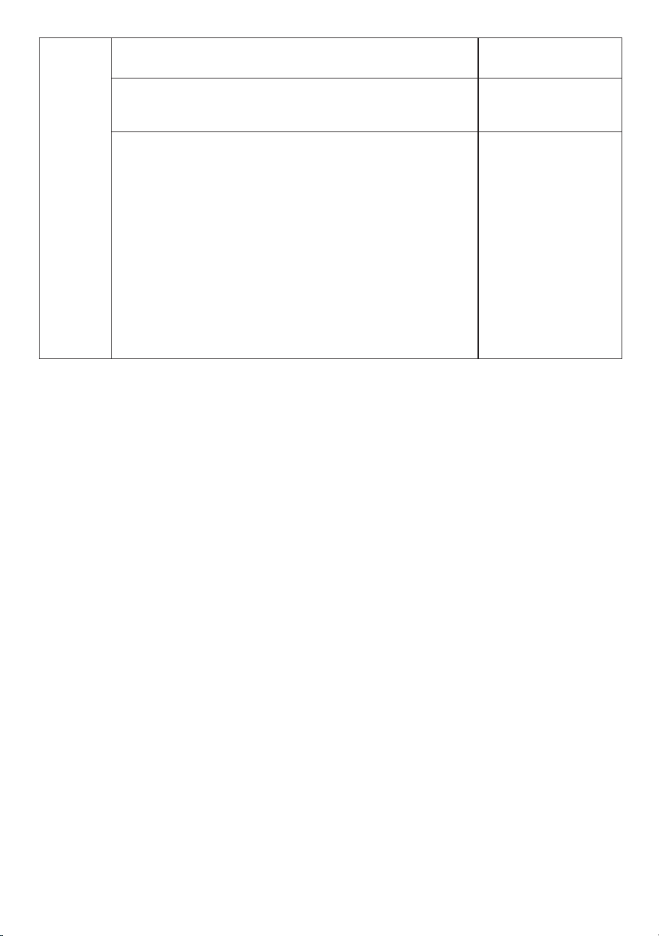
65
E
Appuyez brièvement, les lumières alternent entre un
intensité forte et une intensité moyenne et s’éteignent.
Fixe.
Appuyez de manière prolongée avec toutes les charges
activées (moteur et lumières):
Active/désactive les lumières d’ambiance.
-
Appuyez de manière prolongée avec toutes les charges
éteintes (moteur et lumières):
Configuration du Wi-Fi
Active/désactive la procédure de configuration du Wi-Fi.
Avant de lancer la procédure, utiliser l’application Faber
Cloud pour enregistrer le système Faber IOT. Suivez
ensuite les instructions pour ajouter un nouvel appareil et
enregistrer le routeur de la maison.
Si la procédure n’aboutit pas au bout de quelques
minutes, désactivez-la en appuyant à nouveau
longuement sur la touche, puis faites une nouvelle
tentative. La hotte abandonnera néanmoins la procédure
si elle n’a pas abouti dans les 15 minutes.
Leds D et E
clignotantes:
procédure de
configuration en
cours.
Lorsque la procédure
est terminée avec
succès, les Leds D et
E s'allument pendant
2 secondes.
66
INFORMATIONS SUR LE WI-FI
Ce dispositif est conforme à la Partie 15 des règles de la FCC. Le fonctionnement de
l’appareil doit satisfaire les deux conditions suivantes: (1) cet appareil ne doit pas causer
d’interférences nuisibles, et (2) cet appareil doit accepter toute interférence reçue, y
compris les interférences susceptibles de provoquer un fonctionnement indésirable.
Remarque: Cet équipement a été testé et déclaré conforme aux limites imposées
aux appareils numériques de classe B, conformément à la Partie 15 des règles de
la FCC. Ces limites sont conçues pour fournir une protection raisonnable contre
les interférences nuisibles dans une installation résidentielle. Cet équipement
génère, utilise et peut émettre des fréquences radio et, s’il n’est pas installé et
utilisé conformément aux instructions, peut causer des interférences nuisibles aux
communications radio. Cependant, il n’existe aucune garantie que des interférences
ne se produiront pas dans une installation particulière.
Si cet équipement provoque des interférences nuisibles à la réception de la radio ou
de la télévision, ce qui peut être constaté en éteignant et en rallumant l’équipement,
l’utilisateur est invité à résoudre le problème des interférences en prenant une ou
plusieurs des mesures suivantes:
• Réorienter ou repositionner l’antenne de réception.
• Augmenter la distance entre l’appareil et le récepteur.
• Brancher l’appareil sur une prise d’un circuit différent de celui sur lequel
• le récepteur est branché.
• Consultez votre revendeur ou un technicien radio/TV expérimenté pour obtenir
de l'aide.
Des modifications apportées à ce produit sans l’autorisation de Faber peuvent
invalider la compatibilité électromagnétique (CEM) et la conformité sans fil et
refuser l’autorisation d’utiliser le produit.
Ce produit a démontré sa conformité CEM dans des conditions incluant l’utilisation
de périphériques conformes et de câbles blindés entre les composants du système.
Il est important d’utiliser des périphériques conformes et des câbles blindés entre
les composants du système afin de réduire les risques d’interférences avec les
radios, télévisions et autres appareils électroniques.
Exposition à l'énergie des fréquences radio. La puissance de sortie rayonnée de cet
appareil est conforme aux limites d’exposition aux fréquences radio établis par la
FCC et de l’IC. Cet appareil doit être utilisé en respectant une distance minimum de
20cm (8 pouces) entre l’appareil et le corps d’une personne.
Informations sur l’appareil connecté
Contient la FCC ID: 2AC7Z-ESPS3WROOM1
Contient l’IC: 21098-ESPS3WROOM1
Modèle: ESP32-S3-WROOM-1
CAN ICES-003(B)/NMB-003(B)
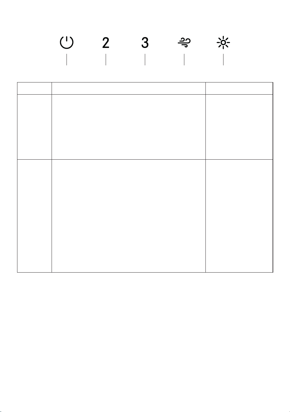
67
A CB D E
CONNEXIONS AU WI-FI
BOUTON FONCTION LED
B
Active/désactive la fonction de Connexion au Wi-Fi.
Appuyez de manière prolongée sur le bouton vitesse 2
avec moteur et lumières éteints pour activer/désactiver
le Wi-Fi.
Remarque: la fonction Wi-Fi est automatiquement
activée lorsque l’utilisateur demande la procédure
de configuration Wi-Fi.
Led D + E
clignotantes:
Connexion au routeur
sans fil de la maison
en cours.
Led D + E fixes:
Connexion au Wi-Fi
activée.
E
Lancer la configuration du Wi-Fi
Appuyez de manière prolongée avec le moteur et
les lumières éteints pour accéder ou terminer la
procédure de configuration du Wi-Fi. Avant de lancer
la procédure, utiliser l’application Faber Cloud pour
enregistrer le système Faber IOT. Suivez ensuite
les instructions pour ajouter un nouvel appareil et
enregistrer votre routeur sans fil domestique.
Si la procédure ne se termine pas correctement au
bout de quelques minutes, arrêtez la procédure de
configuration en maintenant le bouton de fonction
«intensive» enfoncé pendant 3 secondes. Maintenez
à nouveau le bouton enfoncé pendant 3 secondes
pour démarrer la procédure. La hotte interrompra la
procédure de configuration du Wi-Fi si elle n’est pas
terminée avec succès dans les 15 minutes.
Led D + E fixes:
La configuration est
en cours.
Led D + E:
Quand la
configuration est
terminée, les Led
restent allumées
pendant 2 secondes.

68
5. FABER CLOUD APP
The Faber Cloud App is available for
iOS and Android smartphones and al-
lows remote access to all hood func-
tions.
Icon Function
Home page
Add new device
User profile management
Connected to Faber Wi-Fi network
Hood on/off
Lighting system management
Motor speed management
Intensive Function
24h Function
Delay Function
Automatic Function
App settings management
6. REMOTE CONTROL
• This appliance can be controlled us-
ing a remote control.
• ATTENTION: before proceeding, ac-
tivate K-Link Mode on the remote
control (see the device manual for
further details).
7. LIGHTING
• Please contact the Service Depart-
ment to change it ("Please contact
the service department to purchase
it").
8
APPLICATION FABER CLOUD
Application Faber Cloud
Votre hotte est compatible avec l’application Faber Cloud. Tout ce dont vous avez
besoin c’est un réseau Wi-Fi connecté à Internet se trouvant à la portée de la hotte.
Vous pouvez contrôler toutes les fonctions de votre hotte où que vous soyez à l’aide
d’un appareil mobile ou de votre assistant personnel intelligent Alexa d’Amazon ou
Google Home. Lorsque vous êtes connecté à votre assistant personnel intelligent, vous
pouvez contrôler votre hotte avec votre voix.
L’application Faber Cloud est disponible sur les appareils iOS utilisant iOS 11.0 ou une
version plus récente ou sur les appareils Android utilisant Android version 8 ou une
version plus récente. Pour en savoir plus, visitez l’Apple App Store ou le Google Play
Store. Votre hotte fonctionnera parfaitement si vous n’utilisez pas les fonctions Wi-fi
ou l’application Faber Cloud, qui ne sont pas nécessaires.
Pour en savoir plus, consultez le guide de démarrage rapide inclus.
Icône Fonction
5. FABER CLOUD APP
The Faber Cloud App is available for
iOS and Android smartphones and al-
lows remote access to all hood func-
tions.
Icon Function
Home page
Add new device
User profile management
Connected to Faber Wi-Fi network
Hood on/off
Lighting system management
Motor speed management
Intensive Function
24h Function
Delay Function
Automatic Function
App settings management
6. REMOTE CONTROL
• This appliance can be controlled us-
ing a remote control.
• ATTENTION: before proceeding, ac-
tivate K-Link Mode on the remote
control (see the device manual for
further details).
7. LIGHTING
• Please contact the Service Depart-
ment to change it ("Please contact
the service department to purchase
it").
8
Page d’accueil
5. FABER CLOUD APP
The Faber Cloud App is available for
iOS and Android smartphones and al-
lows remote access to all hood func-
tions.
Icon Function
Home page
Add new device
User profile management
Connected to Faber Wi-Fi network
Hood on/off
Lighting system management
Motor speed management
Intensive Function
24h Function
Delay Function
Automatic Function
App settings management
6. REMOTE CONTROL
• This appliance can be controlled us-
ing a remote control.
• ATTENTION: before proceeding, ac-
tivate K-Link Mode on the remote
control (see the device manual for
further details).
7. LIGHTING
• Please contact the Service Depart-
ment to change it ("Please contact
the service department to purchase
it").
8
Ajouter un nouvel appareil
5. FABER CLOUD APP
The Faber Cloud App is available for
iOS and Android smartphones and al-
lows remote access to all hood func-
tions.
Icon Function
Home page
Add new device
User profile management
Connected to Faber Wi-Fi network
Hood on/off
Lighting system management
Motor speed management
Intensive Function
24h Function
Delay Function
Automatic Function
App settings management
6. REMOTE CONTROL
• This appliance can be controlled us-
ing a remote control.
• ATTENTION: before proceeding, ac-
tivate K-Link Mode on the remote
control (see the device manual for
further details).
7. LIGHTING
• Please contact the Service Depart-
ment to change it ("Please contact
the service department to purchase
it").
8
Gestion du profil utilisateur
5. FABER CLOUD APP
The Faber Cloud App is available for
iOS and Android smartphones and al-
lows remote access to all hood func-
tions.
Icon Function
Home page
Add new device
User profile management
Connected to Faber Wi-Fi network
Hood on/off
Lighting system management
Motor speed management
Intensive Function
24h Function
Delay Function
Automatic Function
App settings management
6. REMOTE CONTROL
• This appliance can be controlled us-
ing a remote control.
• ATTENTION: before proceeding, ac-
tivate K-Link Mode on the remote
control (see the device manual for
further details).
7. LIGHTING
• Please contact the Service Depart-
ment to change it ("Please contact
the service department to purchase
it").
8
Connecté au réseau Wi-Fi Faber
5. FABER CLOUD APP
The Faber Cloud App is available for
iOS and Android smartphones and al-
lows remote access to all hood func-
tions.
Icon Function
Home page
Add new device
User profile management
Connected to Faber Wi-Fi network
Hood on/off
Lighting system management
Motor speed management
Intensive Function
24h Function
Delay Function
Automatic Function
App settings management
6. REMOTE CONTROL
• This appliance can be controlled us-
ing a remote control.
• ATTENTION: before proceeding, ac-
tivate K-Link Mode on the remote
control (see the device manual for
further details).
7. LIGHTING
• Please contact the Service Depart-
ment to change it ("Please contact
the service department to purchase
it").
8
Hotte allumée/éteinte
5. FABER CLOUD APP
The Faber Cloud App is available for
iOS and Android smartphones and al-
lows remote access to all hood func-
tions.
Icon Function
Home page
Add new device
User profile management
Connected to Faber Wi-Fi network
Hood on/off
Lighting system management
Motor speed management
Intensive Function
24h Function
Delay Function
Automatic Function
App settings management
6. REMOTE CONTROL
• This appliance can be controlled us-
ing a remote control.
• ATTENTION: before proceeding, ac-
tivate K-Link Mode on the remote
control (see the device manual for
further details).
7. LIGHTING
• Please contact the Service Depart-
ment to change it ("Please contact
the service department to purchase
it").
8
Gestion du système d’éclairage
5. FABER CLOUD APP
The Faber Cloud App is available for
iOS and Android smartphones and al-
lows remote access to all hood func-
tions.
Icon Function
Home page
Add new device
User profile management
Connected to Faber Wi-Fi network
Hood on/off
Lighting system management
Motor speed management
Intensive Function
24h Function
Delay Function
Automatic Function
App settings management
6. REMOTE CONTROL
• This appliance can be controlled us-
ing a remote control.
• ATTENTION: before proceeding, ac-
tivate K-Link Mode on the remote
control (see the device manual for
further details).
7. LIGHTING
• Please contact the Service Depart-
ment to change it ("Please contact
the service department to purchase
it").
8
Gestion de la vitesse du moteur
5. FABER CLOUD APP
The Faber Cloud App is available for
iOS and Android smartphones and al-
lows remote access to all hood func-
tions.
Icon Function
Home page
Add new device
User profile management
Connected to Faber Wi-Fi network
Hood on/off
Lighting system management
Motor speed management
Intensive Function
24h Function
Delay Function
Automatic Function
App settings management
6. REMOTE CONTROL
• This appliance can be controlled us-
ing a remote control.
• ATTENTION: before proceeding, ac-
tivate K-Link Mode on the remote
control (see the device manual for
further details).
7. LIGHTING
• Please contact the Service Depart-
ment to change it ("Please contact
the service department to purchase
it").
8
Fonction «Intensive»
5. FABER CLOUD APP
The Faber Cloud App is available for
iOS and Android smartphones and al-
lows remote access to all hood func-
tions.
Icon Function
Home page
Add new device
User profile management
Connected to Faber Wi-Fi network
Hood on/off
Lighting system management
Motor speed management
Intensive Function
24h Function
Delay Function
Automatic Function
App settings management
6. REMOTE CONTROL
• This appliance can be controlled us-
ing a remote control.
• ATTENTION: before proceeding, ac-
tivate K-Link Mode on the remote
control (see the device manual for
further details).
7. LIGHTING
• Please contact the Service Depart-
ment to change it ("Please contact
the service department to purchase
it").
8
Fonction «Delay» (Retard)
5. FABER CLOUD APP
The Faber Cloud App is available for
iOS and Android smartphones and al-
lows remote access to all hood func-
tions.
Icon Function
Home page
Add new device
User profile management
Connected to Faber Wi-Fi network
Hood on/off
Lighting system management
Motor speed management
Intensive Function
24h Function
Delay Function
Automatic Function
App settings management
6. REMOTE CONTROL
• This appliance can be controlled us-
ing a remote control.
• ATTENTION: before proceeding, ac-
tivate K-Link Mode on the remote
control (see the device manual for
further details).
7. LIGHTING
• Please contact the Service Depart-
ment to change it ("Please contact
the service department to purchase
it").
8
Fonction 24H
5. FABER CLOUD APP
The Faber Cloud App is available for
iOS and Android smartphones and al-
lows remote access to all hood func-
tions.
Icon Function
Home page
Add new device
User profile management
Connected to Faber Wi-Fi network
Hood on/off
Lighting system management
Motor speed management
Intensive Function
24h Function
Delay Function
Automatic Function
App settings management
6. REMOTE CONTROL
• This appliance can be controlled us-
ing a remote control.
• ATTENTION: before proceeding, ac-
tivate K-Link Mode on the remote
control (see the device manual for
further details).
7. LIGHTING
• Please contact the Service Depart-
ment to change it ("Please contact
the service department to purchase
it").
8
Gestion des paramètres de l’application
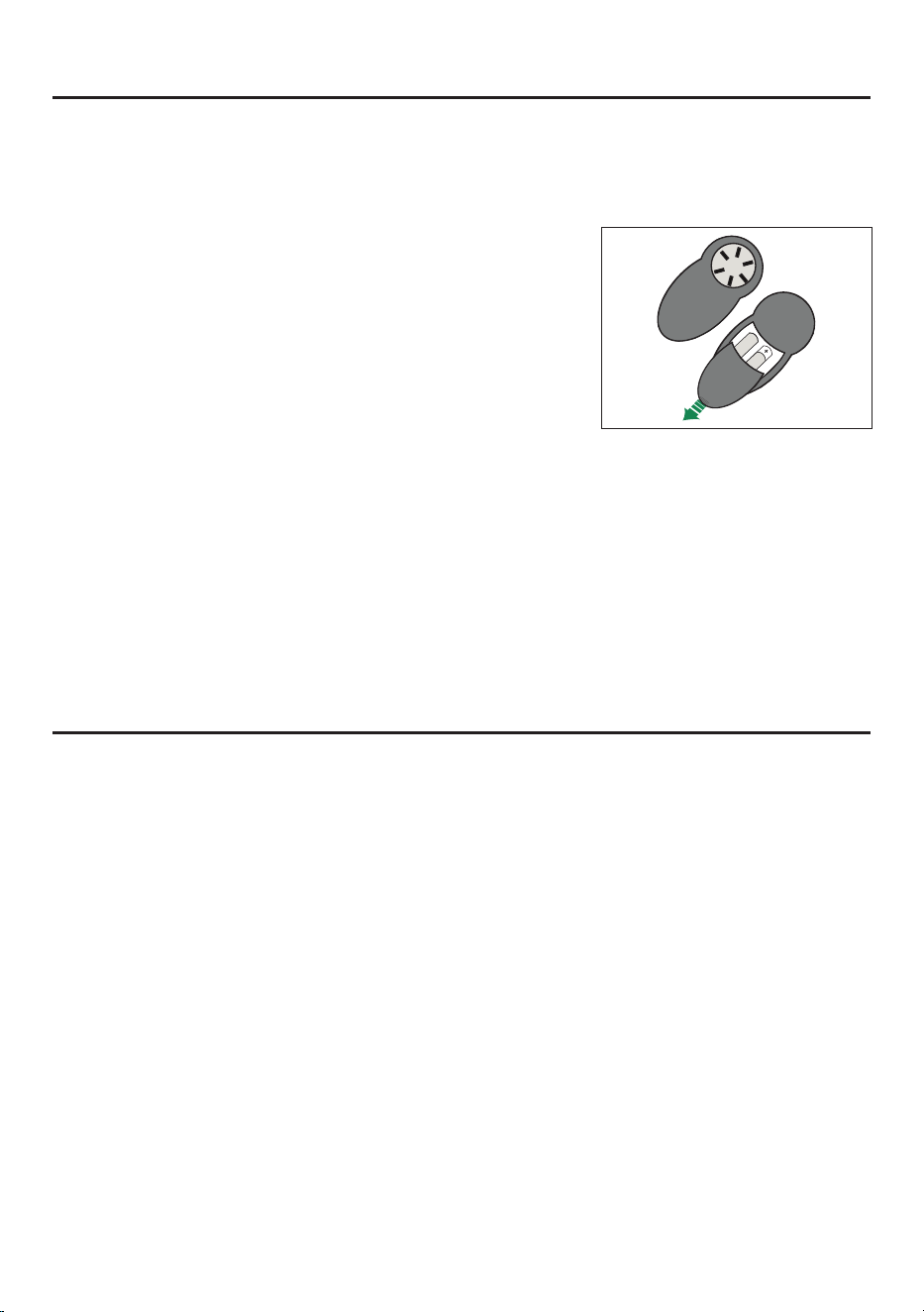
69
TÉLÉCOMMANDE
Vous pouvez contrôlez cet appareil électroménager à l'aide d'une télécommande alimentée
par une pile alcaline carbone-zinc de 1,5 V de type standard LR03-AAA (non incluse).
• Les piles usagées doivent être mises au rebut de manière appropriée.
Attention:
• Ne placez pas la télécommande
à proximité de sources de
chaleur.
• Ne jetez pas les piles avec les
déchets normaux, veuillez les
mettre dans les conteneurs
spéciques.
Nettoyage des surfaces extérieures:
Veuillez noter que les abrasifs et les agents de récurage peuvent rayer les nitions de
la hotte et ne doivent pas être utilisés pour nettoyer les surfaces de nition.
NETTOYAGE DE L'ACIER INOXYDABLE

70
FILTRE À GRAISSE
Veuillez nettoyer ponctuellement le ltre tous les 2 mois, ou plus fréquemment en cas
d’utilisation particulièrement fréquente ; vous pouvez le laver au lave-vaisselle.
NETTOYAGEDUFILTREÀGRAISSEEN
MÉTAL
• Ouvrez le panneau cache-ltre.
• Retirez les ltres un par un en les poussant
vers l’arrière de la hotte et en les tirant
simultanément vers le bas.
• Évitez de déformer le ltre lorsque vous le
lavez. Avant de le remettre en place dans
la hotte, assurez-vous qu’il est parfaitement
sec.
• Lorsque vous installez le ltre dans la hotte,
veillez à ce qu’il soit monté dans la bonne
position, la poignée tournée vers l'extérieur.
• Remettez le cache du ltre en place.
• Assurez-vous que le ltre ne contient
aucune trace d’eau avant de le remettre
en place.
ENTRETIEN
FILTRE AU CHARBON ACTIF
Il ne peut être ni lavé ni régénéré et doit
être changé environ tous les 4 mois, ou
plus fréquemment en cas d’utilisation
particulièrement intensive.
Remplacement du filtre
• Ouvrez le cache du filtre.
• Retirer le filtre à graisse.
• Retirer les filtres à charbon actif saturés.
• Installez les nouveaux filtres.
• Ré-installez le filtre anti-graisse et le
cache de filtre dans son logement.

71
REMPLACEMENTDEL'ÉCLAIRAGE
Veuillez coner le remplacement des LED à un service agréé par Faber.

72
SCHÉMADECÂBLAGE
0 1 2 3 4 5 6 7 8 9
H90_1144
01
Drawing N : Rev :
Modif. by
These drawings and specifications are the property of Franke Technology and
Trademartk Ltd and shall not be reproduced.copied or trasferred to any third party
without the prior written permission of Franke Tecnology and Trandemark Ltd.
Switzerland.It is strictly prohibited to get quotes from the drawing or bring
modifications without the prior written conset of franke Techology and Trademark
Doc.status
Modification description
Approved date
WIRING DIAGR.M8-4V CHA LED WI-FI STS/EXTERNAL
Approved by
Denomination
Doc Type
Creation date
14/10/2024
FABER Corrado
Created by
991.0724.314
Code
USER INTERFACE
CHL
PIN 3
PIN 1
PIN 3
PIN 1
PIN 9
PIN 7
PIN 9
PIN 7
1 2
LED BAR
1 2
1
2
3
4
5
6
7
1
2
3
4
L N
110-127V 60HZ
21
21
21
21
1 2
LED BAR
1 2
1 2
LED BAR
1 2
BRW
L-B
PNK
BLU
WHT
GRY
BLK
RED
M8-4V
BRW
ORG
BLK
GRY
WHT
BLU
BLK
GRY
BLK
GRY
BLU
RED
BLK
BLK
GRY
GRY
BLK

73
GARANTIE
Franke Home Solutions Warranty for Franke and Faber Branded Product
Effective March 1, 2022
In the United States, Canada and Latin America, Franke warrants the Faber branded products from manufacturing defects
in material and workmanship when purchased from a Franke or Faber Authorized Retailer pursuant to product-specific
warranties detailed herein (each, a “Warranty” and collectively, the “Warranties”). The products must be properly installed,
per Franke’s installation instructions, in their original installation, and used in normal indoor residential kitchen
applications. Any products or components which have been modified or altered from their original intended condition will
void the Warranty. The Franke Warranties for Faber branded products are limited to the original purchaser and are non-
transferrable. These Warranties do not include products purchased from non-Authorized Retailers, products that are
obsolete or discontinued, or products that were previous display models. All issues with installed products are considered
warranty claims and not subject to the Return Policy. Franke reserves the right to inspect any Franke / Faber product
reported to be defective pursuant to a Warranty claim and the original installation prior to providing a replacement product
and/or component. All decisions are final. In no situation shall the liability of Franke exceed the amount of the original
purchase price.
The Warranties do not cover, and Franke shall not be liable for, any damage to products or components resulting from
misuse or abuse, accidental damages, normal wear such as scuffs, scratches or finish reduction/fading, improper
installation, abnormal usage, negligence, damage caused by improper maintenance or cleaning. Damage caused by
impurities, corrosive chemicals or acts beyond Franke’s control are not covered by any Warranty. Service calls to correct
the installation of a range hood, instructions on how to operate a range hood, to replace or repair house fuses or to correct
house wiring or plumbing are not covered by any Warranty. Service calls to repair or replace range hood light bulbs, fuses
or filters and these consumable part costs are also excluded from Warranty coverage. Installation not in accordance with
electrical or plumbing codes or Franke / Faber documentation are not covered by any Warranty. Replacement parts or
repair labor costs for units operated outside the United States, Canada or Latin America, including any non-UL or C-UL or
non-NOM approved Franke / Faber range hoods are excluded from Warranty coverage. Expenses for travel and
transportation for service in remote locations and pickup and delivery charges are not covered by any Warranty. Franke /
Faber range hoods should always be serviced in the home in their original installation.
Franke / Faber product replacements do not include liability for project delays. Product replacements are not guaranteed
to be exact replacements. If the original product is not available at the time of the warranty claim, at Franke’s option, the
product replacements will be of similar size, material, and value. Any products or components which have been modified
or altered, from its original intended condition will void the warranty.
The Warranties do not allow recovery of incidental or consequential damages such as loss of use, delay, property
damage or other consequential damage, and Franke accepts no liability for such damages. Each Warranty is limited to
the conditions set forth herein and to the applicable warranty period specified herein and is exclusive. EXCEPT FOR THE
WARRANTIES SET FORTH HEREIN, FRANKE MAKES NO WARRANTY WHATSOEVER WITH RESPECT TO THE
PRODUCTS, INCLUDING, BUT NOT LIMITED TO, (1) ANY WARRANTY OF MERCHANTABILITY, (2) WARRANTY OF
FITNESS FOR A PARTICULAR PURPOSE, (3) WARRANTY OF TITLE, OR (4) WARRANTY AGAINST INFRINGEMENT
OF INTELLECTUAL PROPERTY RIGHTS OF A THIRD PARTY, WHETHER EXPRESS OR IMPLIED BY LAW, COURSE
OF DEALING, COURSE OF PERFORMANCE, USAGE OF TRADE OR OTHERWISE. LEGAL DISCLAIMER PLEASE
READ CAREFULLY. Franke Kitchen Systems LLC provides the above information to you as a public service to our
customers. By accessing and using this information, you agree to the following and to comply with all applicable laws. If
you do not agree with these terms and conditions, do not use this information. While we try to keep the information
current, changes may have occurred since its creation. Contact your Regional Manager or Customer Service to verify
information regarding Franke Kitchen Systems LLC programs and their use by you.
Franke / Faber Range Hood Limited Warranty:
Franke / Faber range hoods are warranted against any defect in materials or workmanship for the original purchaser for a
period of two (2) years from the date of original purchase when used in standard residential indoor applications. This
warranty covers labor and replacement parts. Franke, at its option, may repair or replace the product or components
necessary to restore the product to good working condition.
Garantie Franke Home Solutions pour les produits de marque Franke et Faber en vigueur le 1ermars2022
Aux États-Unis, au Canada et en Amérique latine, Franke garantit les produits de la marque Faber contre les défauts de
fabrication des matériaux et de la fabrication lorsqu’ils sont achetés auprès d’un revendeur agréé Franke ou Faber conformément
aux garanties spécifiques aux produits détaillées dans le présent document (chacune, une «garantie» et collectivement, les
«garanties»). Les produits doivent être correctement installés, conformément aux instructions d’installation de Franke, dans leur
installation d’origine, et utilisés dans des applications de cuisine résidentielles intérieures normales. Tout produit ou composant
qui a été modifié ou altéré par rapport à son état d’origine annulera la garantie. Les garanties Franke pour les produits de marque
Faber sont limitées à l’acheteur d’origine et ne sont pas transférables. Ces garanties n’incluent pas les produits achetés auprès de
revendeurs non agréés, les produits obsolètes ou abandonnés, ou les produits qui étaient des modèles précédemment affichés.
Tous les problèmes avec les produits installés sont considérés comme des demandes de garantie et ne sont pas soumis à la
politique de retour. Franke se réserve le droit d’inspecter tout produit Franke/Faber signalé comme défectueux en vertu d’une
réclamation au titre de la garantie et de l’installation d’origine avant de fournir un produit et/ou un composant de remplacement.
Toutes les décisions sont finales. La responsabilité de Franke ne pourra en aucun cas dépasser le montant du prix d’achat initial.
Les garanties ne couvrent pas, et Franke ne sera pas tenue responsable, de tout dommage aux produits ou composants résultant
d’une mauvaise utilisation ou d’un abus, de dommages accidentels, d’une usure normale telle que des éraflures, des rayures ou
d’une réduction/décoloration du fini, d’une installation incorrecte, d’une utilisation anormale, d’une négligence, des dommages
causés par un entretien ou un nettoyage inapproprié. Les dommages causés par des impuretés, des produits chimiques corrosifs
ou des actes indépendants de la volonté de Franke ne sont couverts par aucune garantie. Les appels de service pour corriger
l’installation d’une hotte de cuisinière, les instructions sur la façon de faire fonctionner une hotte de cuisinière, pour remplacer ou
réparer les fusibles de la maison ou pour corriger le câblage ou la plomberie de la maison ne sont couverts par aucune garantie.
Les appels de service pour réparer ou remplacer les ampoules, les fusibles ou les filtres de la hotte de cuisinière et ces coûts de
pièces consommables sont également exclus de la couverture de la garantie. Une installation non conforme aux codes électriques
ou de plomberie ou à la documentation Franke/Faber n’est couverte par aucune garantie. Les pièces de rechange ou les coûts de
main-d’œuvre de réparation pour les unités utilisées à l’extérieur des États-Unis, du Canada ou de l’Amérique latine, y compris les
hottes de cuisinière Franke/Faber non approuvées UL ou C-UL ou NOM, sont exclus de la couverture de la garantie. Les frais de
déplacement et de transport pour l’entretien dans des endroits éloignés et les frais de ramassage et de livraison ne sont couverts
par aucune garantie. Les hottes de cuisinière Franke/Faber doivent toujours être entretenues à domicile dans leur installation
d’origine.
Les remplacements de produits Franke/Faber n’incluent pas la responsabilité pour les retards de projet. Les remplacements de
produits ne sont pas garantis comme étant des remplacements exacts. Si le produit d’origine n’est pas disponible au moment
de la demande de garantie, à la discrétion de Franke, les produits de remplacement seront de taille, de matériau et de valeur
similaires. Tout produit ou composant qui a été modifié ou altéré par rapport à son état d’origine annulera la garantie.
Les garanties n’autorisent pas le recouvrement des dommages indirects ou consécutifs tels que la perte d’utilisation, le retard,
les dommages matériels ou autres dommages consécutifs, et Franke décline toute responsabilité pour ces dommages. Chaque
garantie est limitée aux conditions énoncées dans le présent document et à la période de garantie applicable spécifiée dans le
présent document et est exclusive. À L’EXCEPTION DES GARANTIES ÉNONCÉES DANS LE PRÉSENT DOCUMENT, FRANKE
N’OFFRE AUCUNE GARANTIE CONCERNANT LES PRODUITS, Y COMPRIS, MAIS SANS S’Y LIMITER, (1) TOUTE GARANTIE DE
QUALITÉ MARCHANDE, (2) GARANTIE D’ADÉQUATION À UN USAGE PARTICULIER, (3) GARANTIE DE TITRE DE PROPRIÉTÉ,
OU (4) GARANTIE CONTRE LA VIOLATION DES DROITS DE PROPRIÉTÉ INTELLECTUELLE D’UN TIERS, QU’ELLE SOIT
EXPRESSE OU IMPLICITE PAR LA LOI, LE COURS DES AFFAIRES, LE COURS DE L’EXÉCUTION, L’USAGE DU COMMERCE OU
AUTREMENT. AVIS DE NON-RESPONSABILITÉ LÉGALE, VEUILLEZ
LIRE ATTENTIVEMENT. Franke Kitchen SystemsLLC vous fournit les informations ci-dessus en tant que service public à nos
clients. En accédant à ces informations et en les utilisant, vous acceptez ce qui suit et vous vous conformez à toutes les lois
applicables. Si vous n’êtes pas d’accord avec ces termes et conditions, n’utilisez pas ces informations. Bien que nous essayions de
maintenir l’information à jour, des changements peuvent avoir eu lieu depuis sa création. Contactez votre directeur régional ou le
service client pour vérifier les informations concernant les programmes Franke Kitchen SystemsLLC et leur utilisation par vous.
Garantie limitée des hottes de cuisinière Franke/Faber:
Les hottes de cuisinière Franke/Faber sont garanties contre tout défaut de matériaux ou de fabrication pour l’acheteur d’origine
pendant une période de deux(2) ans à compter de la date d’achat d’origine lorsqu’elles sont utilisées dans des applications
intérieures résidentielles normales. Cette garantie couvre la main-d’œuvre et les pièces de rechange. Franke, à sa discrétion, peut
réparer ou remplacer le produit ou les composants nécessaires pour remettre le produit en bon état de fonctionnement.

74
Franke Home Solutions Warranty for Franke and Faber Branded Product
Effective March 1, 2022
In the United States, Canada and Latin America, Franke warrants the Faber branded products from manufacturing defects
in material and workmanship when purchased from a Franke or Faber Authorized Retailer pursuant to product-specific
warranties detailed herein (each, a “Warranty” and collectively, the “Warranties”). The products must be properly installed,
per Franke’s installation instructions, in their original installation, and used in normal indoor residential kitchen
applications. Any products or components which have been modified or altered from their original intended condition will
void the Warranty. The Franke Warranties for Faber branded products are limited to the original purchaser and are non-
transferrable. These Warranties do not include products purchased from non-Authorized Retailers, products that are
obsolete or discontinued, or products that were previous display models. All issues with installed products are considered
warranty claims and not subject to the Return Policy. Franke reserves the right to inspect any Franke / Faber product
reported to be defective pursuant to a Warranty claim and the original installation prior to providing a replacement product
and/or component. All decisions are final. In no situation shall the liability of Franke exceed the amount of the original
purchase price.
The Warranties do not cover, and Franke shall not be liable for, any damage to products or components resulting from
misuse or abuse, accidental damages, normal wear such as scuffs, scratches or finish reduction/fading, improper
installation, abnormal usage, negligence, damage caused by improper maintenance or cleaning. Damage caused by
impurities, corrosive chemicals or acts beyond Franke’s control are not covered by any Warranty. Service calls to correct
the installation of a range hood, instructions on how to operate a range hood, to replace or repair house fuses or to correct
house wiring or plumbing are not covered by any Warranty. Service calls to repair or replace range hood light bulbs, fuses
or filters and these consumable part costs are also excluded from Warranty coverage. Installation not in accordance with
electrical or plumbing codes or Franke / Faber documentation are not covered by any Warranty. Replacement parts or
repair labor costs for units operated outside the United States, Canada or Latin America, including any non-UL or C-UL or
non-NOM approved Franke / Faber range hoods are excluded from Warranty coverage. Expenses for travel and
transportation for service in remote locations and pickup and delivery charges are not covered by any Warranty. Franke /
Faber range hoods should always be serviced in the home in their original installation.
Franke / Faber product replacements do not include liability for project delays. Product replacements are not guaranteed
to be exact replacements. If the original product is not available at the time of the warranty claim, at Franke’s option, the
product replacements will be of similar size, material, and value. Any products or components which have been modified
or altered, from its original intended condition will void the warranty.
The Warranties do not allow recovery of incidental or consequential damages such as loss of use, delay, property
damage or other consequential damage, and Franke accepts no liability for such damages. Each Warranty is limited to
the conditions set forth herein and to the applicable warranty period specified herein and is exclusive. EXCEPT FOR THE
WARRANTIES SET FORTH HEREIN, FRANKE MAKES NO WARRANTY WHATSOEVER WITH RESPECT TO THE
PRODUCTS, INCLUDING, BUT NOT LIMITED TO, (1) ANY WARRANTY OF MERCHANTABILITY, (2) WARRANTY OF
FITNESS FOR A PARTICULAR PURPOSE, (3) WARRANTY OF TITLE, OR (4) WARRANTY AGAINST INFRINGEMENT
OF INTELLECTUAL PROPERTY RIGHTS OF A THIRD PARTY, WHETHER EXPRESS OR IMPLIED BY LAW, COURSE
OF DEALING, COURSE OF PERFORMANCE, USAGE OF TRADE OR OTHERWISE. LEGAL DISCLAIMER PLEASE
READ CAREFULLY. Franke Kitchen Systems LLC provides the above information to you as a public service to our
customers. By accessing and using this information, you agree to the following and to comply with all applicable laws. If
you do not agree with these terms and conditions, do not use this information. While we try to keep the information
current, changes may have occurred since its creation. Contact your Regional Manager or Customer Service to verify
information regarding Franke Kitchen Systems LLC programs and their use by you.
Franke / Faber Range Hood Limited Warranty:
Franke / Faber range hoods are warranted against any defect in materials or workmanship for the original purchaser for a
period of two (2) years from the date of original purchase when used in standard residential indoor applications. This
warranty covers labor and replacement parts. Franke, at its option, may repair or replace the product or components
necessary to restore the product to good working condition.
Cette garantie remplace toutes les autres garanties, expresses ou implicites. Aucun employé, représentant
commercial sur le terrain ou distributeur n’est autorisé à donner des garanties au nom de Franke Kitchen
Systems, LLC.
Pour faire une réclamation au titre de la garantie d’un produit installé, veuillez contacter Franke aux
coordonnées fournies ci-dessous. Toutes les réclamations de garantie doivent inclure les éléments suivants
pour le traitement:
1. Preuve d’achat auprès d’un revendeur agréé Franke ou Faber
2. Nom, adresse (ville, état, code postal) de l’acheteur d’origine, adresse de courrier électronique et
numéro de téléphone
3. Modèle et numéro de série Franke/Faber
4. Date d’installation
5. Description du défaut
6. Photos du défaut
En Amérique du Nord et en Amérique Latine:
Franke Home Solutions
À l’attention de: Warranty Department
800 Aviation Parkway
Smyrna, TN 37167
HS-Warranty.US@Franke.com
Raison sociale:
Franke Kitchen Systems LLC

75
CONTENIDOS
Sección Página
Instrucciones importantes de seguridad
76
Dimensiones de la campana extractora
81
Requerimientos de altura para la instalación
82
Piezas
83
Herramientas necesarias
85
Preparación de la instalación de la campana de techo
86
Información sobre la instalación
88
Instalación del cuerpo de la campana extractora
89
Instrucciones de montaje en techo
91
Conexiones eléctricas
98
Operación de los controles
101
Aplicación Faber Cloud
105
Control remoto
106
Limpieza del acero inoxidable
106
Mantenimiento
107
Sustitución de la iluminación
108
Diagrama de cableado
109
Garantía
110

76
INSTRUCCIONESIMPORTANTESDESEGURIDAD
LEA Y GUARDE ESTAS INSTRUCCIONES ANTES DE COMENZAR A
INSTALAR ESTA CAMPANA EXTRACTORA
ATENCIÓN: - PARA REDUCIR EL RIESGO DE INCENDIO DE GRASA:
a) Nunca deje las unidades de superficie desatendidas en ajustes altos. Las ebulli-
ciones causan humo y derrames grasientos que pueden encenderse. Caliente los
aceites lentamente en ajustes bajos o medios.
b) Siempre encienda la campana cuando cocine a fuego alto o cuando flamee ali-
mentos (por ej. Crepes Suzette, Cherries Jubilee, Peppercorn Beef Flambé).
c) Limpie los sopladores con frecuencia. No se debe permitir que la grasa se acu-
mule en el soplador o filtro.
d) Use un tamaño de olla adecuado. Siempre use utensilios de cocina apropiados
para el tamaño del elemento de superficie.
ADVERTENCIA: - PARA REDUCIR EL RIESGO DE LESIONES A PERSONAS EN CASO
DE INCENDIO DE GRASA, TENGA CUENTA LO SIGUIENTE*:
a) APAGUE LAS LLAMAS con una tapa ajustada, bandeja para hornear galletas o
bandeja de metal, luego apague el quemador. TENGA CUIDADO PARA EVITAR
QUEMADURAS. Si las llamas no se apagan de inmediato, EVACUE Y LLAME AL
DEPARTAMENTO DE BOMBEROS.
b) NUNCA RECOJA UNA OLLA EN LLAMAS - Puede quemarse.
c) NO USE AGUA, incluidos paños de cocina húmedos o toallas; se producirá una
violenta explosión de vapor.
d) Use un extintor SOLAMENTE si:
1. Usted sabe que tiene un extintor Clase ABC y ya sabe cómo operarlo.
2. El fuego es pequeño y está contenido en el área donde comenzó.
3. Llame al departamento de bomberos.
4. Puede luchar contra el fuego con su espalda hacia una salida.
* Basado en "Kitchen Firesafety Tips" publicado por NFPA
ADVERTENCIA - PARA REDUCIR EL RIESGO DE DESCARGA ELÉCTRICA O INCEN-
DIO, no use este soplador con ningún dispositivo de control de velocidad de estado.
ADVERTENCIA - PARA REDUCIR EL RIESGO DE INCENDIOS, DESCARGAS ELÉC-
TRICAS O LESIONES PERSONALES, OBSERVE LO SIGUIENTE:
1. Use esta unidad solo de la manera prevista por el fabricante. Si tiene alguna
pregunta, comuníquese con el fabricante.
2. Antes de reparar o limpiar la unidad, apague el equipo en el panel de servicio
y bloquee los medios de desconexión del servicio para evitar que la energía se
encienda accidentalmente. Cuando los medios de desconexión del servicio no se
puedan bloquear, fije de forma segura un dispositivo de advertencia prominente,
como una etiqueta, al panel de servicio.
PRECAUCIÓN: Para uso general de ventilación solamente. No lo use para expulsar
materiales y vapores peligrosos o explosivos.
ADVERTENCIA - PARA REDUCIR EL RIESGO DE INCENDIOS, DESCARGAS ELÉC-
TRICAS O LESIONES PERSONALES, OBSERVE LO SIGUIENTE:
1. El trabajo de instalación y el cableado eléctrico deben realizarlo las personas
calificadas de acuerdo con todos los códigos y estándares aplicables, incluida
la construcción con clasificación de incendio.
2. Se necesita suficiente aire para la combustión adecuada y el escape de gases a
través del tubo de humos (chimenea) del equipo que quema combustible para

77
evitar la retrogresión. Siga las directrices del fabricante del equipo de calefacción
y las normas de seguridad tales como los publicados por la National Fire Pro-
tection Association (NFPA), la American Society for Heating, Refrigeration and
Air Conditioning Engineers (ASHRAE) y las autoridades de los códigos locales.
3. Al cortar o perforar la pared o el techo, no dañe el cableado eléctrico ni otros
servicios ocultos.
4. Losventiladorescanalizadosutilizadosparaextraercontaminantessiempre
debenventilarsehaciaelexterior.
TODAS LAS ABERTURAS DE LA PARED Y EL PISO DONDE ESTÁ INSTALADA LA
CAMPANA EXTRACTORA SE DEBEN SELLAR.
Esta campana extractora requiere al menos 30" de espacio libre entre la parte inferior
de la campana y la superficie de cocción o encimera. Esta campana ha sido aprobada
por UL a esta distancia de la placa.
Consulte las instrucciones de instalación de la placa o la campana proporcionadas por el
fabricante antes de hacer cualquier corte. INSTALACIÓN EN CASA MÓVIL La instalación
de esta campana extractora debe cumplir con las Normas de seguridad y construcción
de viviendas prefabricadas, Título 24 CFR, Parte 3280 (anteriormente Norma federal
para construcción y seguridad de casas móviles, Título 24, HUD, Parte 280).
Atención: Esta campana ha sido diseñada para minimizar la interferencia
electromagnética (EMI) que se origina en la fuente de alimentación doméstica del
consumidor. Sin embargo, en algunas aplicaciones domésticas, la EMI ambiental y la
EMI excesiva de otras fuentes electrónicas pueden afectar la fiabilidad del mando a
distancia.
Hable con su distribuidor Faber acerca de una pieza de repuesto opcional para reducir
aún más la EMI de fuentes domésticas.
REQUISITOS DE VENTILACIÓN
Determine qué método de ventilación es mejor para su aplicación. Los conductos pue-
den extenderse a través de la pared o el techo.
La longitud de los conductos y la cantidad de codos se deben mantener al mínimo para
proporcionar un rendimiento eficiente. El tamaño de los conductos debe ser uniforme.
No instales dos codos juntos. Use cinta adhesiva para sellar todas las juntas en el sis-
tema de conductos. Use masilla para sellar la pared exterior o la abertura del espacio
del techo alrededor de la tapa.
No se recomiendan conductos flexibles. Los conductos flexibles crean una contra-
presión y turbulencias de aire que reducen en gran medida el rendimiento.
Asegúrese de que haya espacio libre adecuado dentro de las paredes y espacio en
el piso para el conducto de escape antes de hacer los cortes. No corte una vigueta o
poste a menos que sea absolutamente necesario. Si se debe cortar una vigueta o poste,
entonces se debe construir un marco de soporte.
ADVERTENCIA - Para reducir el riesgo de incendio, use solamente conductos de metal.
PRECAUCIÓN - Para reducir el riesgo de incendio y para descargar adecuadamente
el aire, asegúrese de sacar el aire - No expulse los humos en espacios dentro de
paredes o techos, áticos, espacios angostos o garajes.
ADVERTENCIA: Para Reducir el Riesgo de Incendio, Descarga Eléctrica o Lesiones
Personales, No Utilice Piezas de Recambio Que No Hayan Sido Recomendadas Por
El Fabricante (por ejemplo, Piezas Fabricadas En Casa Usando Una impresora 3D).
78
Instalaciones para clima frío
Se debe instalar un registro de retrogresión para minimizar el flujo de aire frío hacia
atrás y se debe instalar un interruptor térmico no metálico para minimizar la conducción
de temperaturas externas como parte del sistema de ventilación. El registro debe estar
en el lado del aire frío del interruptor térmico. El interruptor debe estar lo más cerca
posible de donde el sistema de ventilación ingrese a la parte calentada de la casa.
• El sistema de ventilación DEBE terminar fuera del hogar.
• NO termine el conducto en un espacio ático o en otro espacio cerrado.
• NO use tapones de pared de 4" tipo lavadero.
• No se recomiendan conductos flexibles.
• NO obstruya el flujo del aire de combustión y ventilación.
• El incumplimiento de los requisitos de ventilación puede provocar un
incendio.
ADVERTENCIA
!
79
REQUISITOS ELÉCTRICOS
Se requiere un suministro eléctrico de 120 voltios, 60 Hz solo CA en un circuito separado
con fusible de 15 amperios. Se recomienda un fusible de retardo o un cortacircuitos. El
fusible se debe dimensionar según los códigos locales de acuerdo con la clasificación
eléctrica de esta unidad, tal como se especifica en la placa de número de serie/clasifi-
cación ubicada dentro de la unidad, cerca del compartimento de cableado de campo.
INSTALACIÓN ELÉCTRICA CON CAJA DE CABLEADO
ESTA UNIDAD DEBE CONECTARSE CON CABLE DE COBRE SOLAMENTE. Los ta-
maños de los cables deben cumplir con los requisitos del Código Eléctrico Nacional,
ANSI / NFPA 70, última edición, y todos los códigos y ordenanzas locales. El tamaño
del cable y las conexiones deben cumplir con la clasificación del equipo. Se pueden
obtener copias de la norma enumerada anteriormente en:
National Fire Protection Association
Batterymarch Park
Quincy, Massachusetts 02269
Este electrodoméstico debe conectarse directamente a la desconexión por fusible
(o disyuntor) a través de un cable flexible, blindado o no metálico de cobre enfunda-
do. Deje algo de tensión en el cable para poder mover el dispositivo si alguna vez lo
necesita. Debe haber un conector de conducto de 1/2 homologado por UL en cada
extremo del cable de suministro de energía (en el equipo y en la caja de conexiones).
Al hacer la conexión eléctrica, corte un agujero de 1 1/4 ". Un agujero cortado a través
de la madera debe lijarse hasta que quede liso. Un agujero a través del metal debe
tener un ojal.
• Esta campana extractora requiere conexión eléctrica de tierra.
• Si la tubería de agua fría está interrumpida por juntas de plástico, de
materiales no metálicos u otros materiales, NO la utilice para conexión a
tierra.
• NO conecte a tierra a una tubería de gas.
• NO tenga un fusible en el circuito neutro o de tierra. Un fusible en el circuito
neutro o de tierra podría provocar una descarga eléctrica.
• Consulte con un electricista calificado si tiene dudas acerca de si la campana
extractora está correctamente conectada a tierra.
• El incumplimiento de los requisitos eléctricos puede provocar un incendio.
ADVERTENCIA
!

80
PRECAUCIÓN: Las piezas accesibles pueden calentarse cuando se utilizan con
aparatos de cocina.
•Elairenodebedescargarseenunconductodehumosqueseutilizaparaexpulsar
los humos de aparatos que queman gas u otros combustibles.
•SiunAPARATOESTACIONARIOnoestáequipadoconunCORDDEALIMENTACIÓN
yunenchufe,oconotrosmediosdedesconexióndelaredeléctricaquetengan
unaseparacióndecontactosentodoslospolosqueprevealadesconexióntotal
encondicionesdesobretensióndecategoríalII,lasinstruccionesdeberánindicar
quémediosparaLadesconexióndebeincorporarseenelcableadojodeacuerdo
con las normas de cableado.
•Ladesconexiónsepodrárealizarteniendoaccesibleelenchufeoincorporandoun
interruptorenelcableadojodeacuerdoconlasnormasdecableado.
•Estedispositivonoestádiseñadoparaqueloutilicenpersonas(incluidosniños)
cuyascapacidadesfísicas,sensorialesomentalesseandiferentesoreducidas,o
quecarezcandeexperienciaoconocimiento,amenosquedichaspersonasreciban
supervisiónocapacitaciónparaelfuncionamientodeldispositivoporpartede
una persona responsable de su seguridad.
•Sedebesupervisaralosniñosparaasegurarsedequenoutilicenlosdispositivos
como juguetes.
•Noameealimentosdebajodelacampanaextractora.
•elairenodebedescargarseenunconductodehumosqueseutilizaparaexpul-
sarloshumosdeaparatosquequemangasuotroscombustibles(noaplicablea
aparatosquesólodescarganelairederegresoalahabitación);
•debehaberunaventilaciónadecuadadelahabitacióncuandolacampanaextrac-
tora se utiliza al mismo tiempo que aparatos que queman gas u otros combustibles
(noaplicableaaparatosquesólodescarganelairederegresoalahabitación);
•existeriesgodeincendiosilalimpiezanoserealizasegúnlasinstrucciones;
•Esteaparatodebeestarconectadoatierra.Encasodeuncortocircuitoeléctrico,
laconexiónatierrareduceelriesgodedescargaeléctricaalproporcionaruncable
deescapeparalacorrienteeléctrica.Esteaparatoestáequipadoconuncable
quetieneuncableatierraconunenchufeatierra.Elenchufedebeenchufarsea
untomacorrientequeestécorrectamenteinstaladoyconectadoatierra.
ADVERTENCIA: una conexión a tierra inadecuada puede provocar un riesgo de
descargaeléctrica.
•Consulteaunelectricistacalicadosinocomprendecompletamentelasinstruc-
cionesdeconexiónatierraosiexistedudasobresielaparatoestáconectadoa
tierra correctamente.
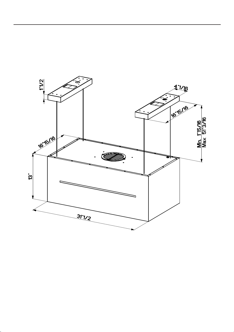
81
17-Oct-2024
Released
DIMENSIONESDELACAMPANAEXTRACTORA

82
REQUERIMIENTOSDEALTURAPARALAINSTALACIÓN
Se recomienda una altura de montaje de 30" por encima de la superficie de cocción
para obtener el mejor rendimiento, pero puede montarse a una distancia máxima de
72" de la superficie de cocción.
Es necesario hacer un punto de acceso a la campana desde el techo para la instalación
y el futuro acceso a la campana extractora.
MÍNIMO. 30" SOBRE ELÉCTRICA / GAS
Instalación Sin Conducto
Esta campana está diseñada para ser montada en el techo, y sólo en modo
Recirculación.
Se requiere de tres personas para la
instalación
Use guantes de trabajo para la
seguridad
MÁX. 72" SOBRE ELÉCTRICA O GAS
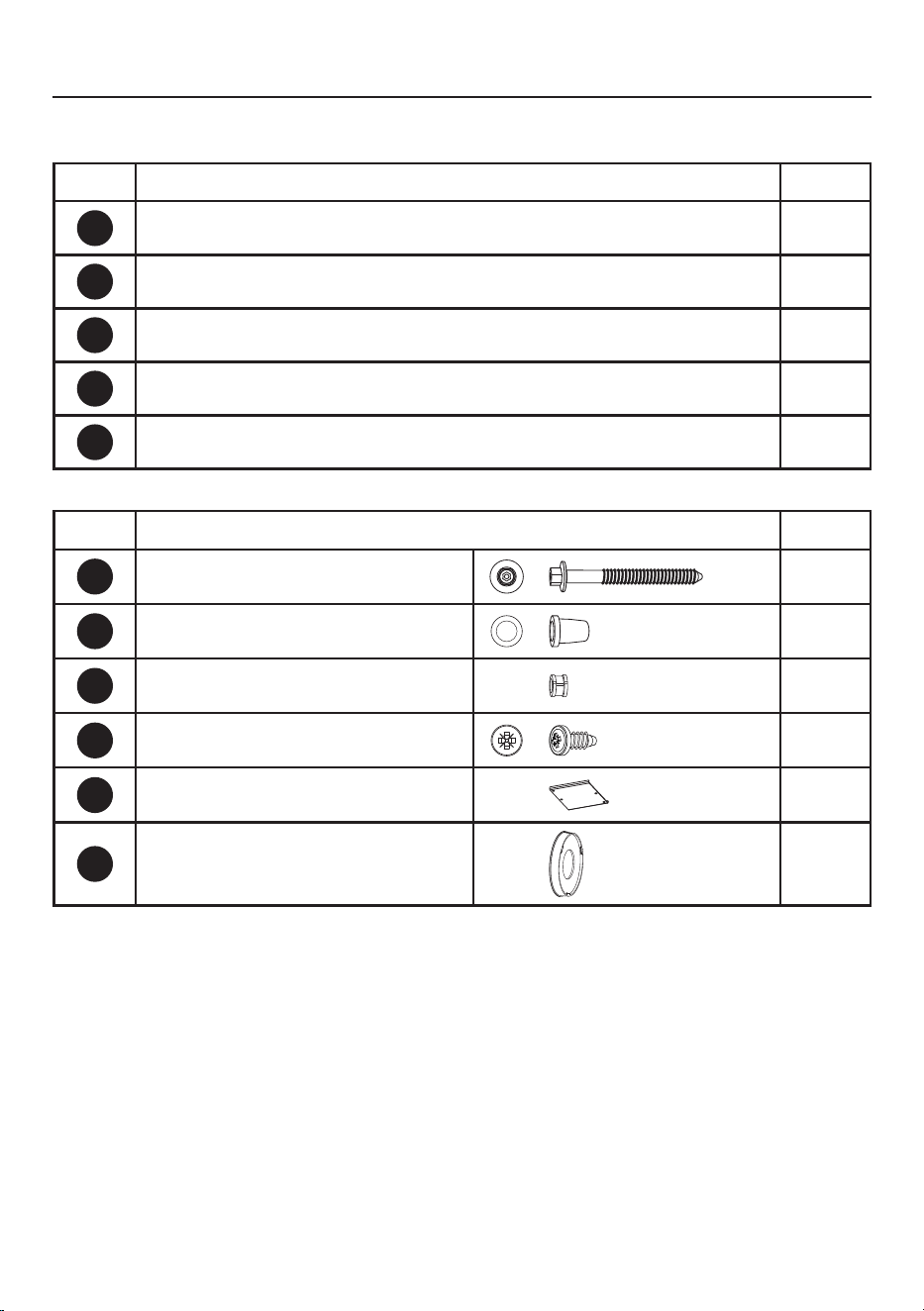
83
PIEZAS
PIEZASINCLUIDAS
REF. PIEZA CANT
A
Cuerpo de la campana dotado de: Controles, Luces, Filtros. 1
E
Control remoto 1
H
Plantilla de perforación 1
L
Soporte del techo 2
I
Cable del techo 4
REF
PIEZA
CANT
C
Tornillos 4/16" x 2-12/16" 8
O
Tope transparente 1
O1
Tope 1
P
Tornillos 2/16" x 4/16" 2
R1
Cubierta del terminal 1
W
Filtro de Carbón Vegetal 2
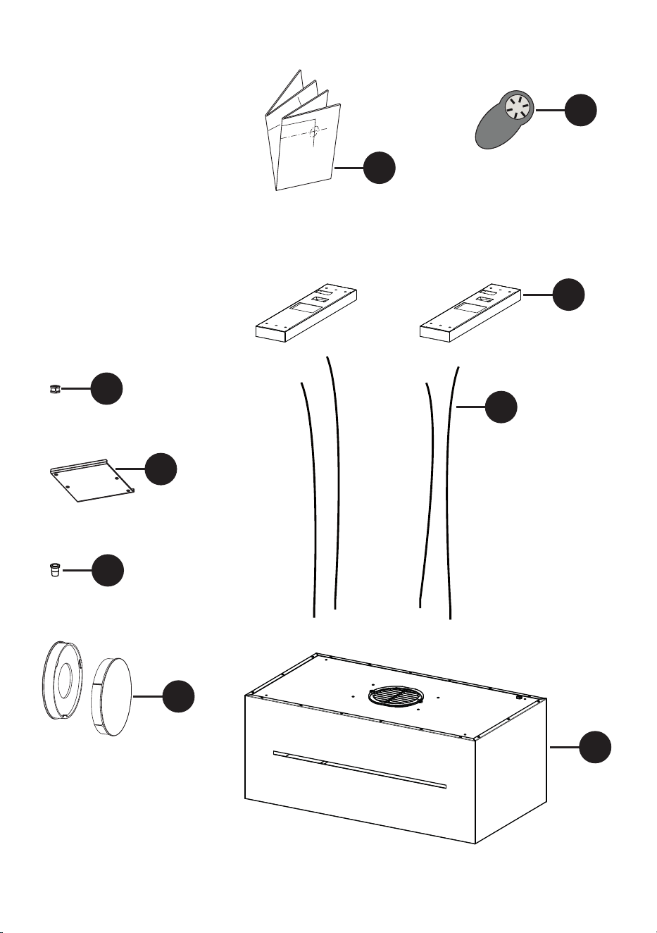
84
8
AA-725973-1
1x
1x
C
1x
B
A
1x
3x 4x
1x
D E
1x
1x
1x
1x
H
O
I
A
E
L
W
R1
O1

85
PIEZAS NECESARIAS
PIEZAS(cont.)
PIEZA
Conectores de cables.
HERRAMIENTAS NECESARIAS
HERRAMIENTA
Cinta Métrica
Lápiz
Taladro Eléctrico con Broca de 5/16
Destornillador Phillips
Guantes de trabajo
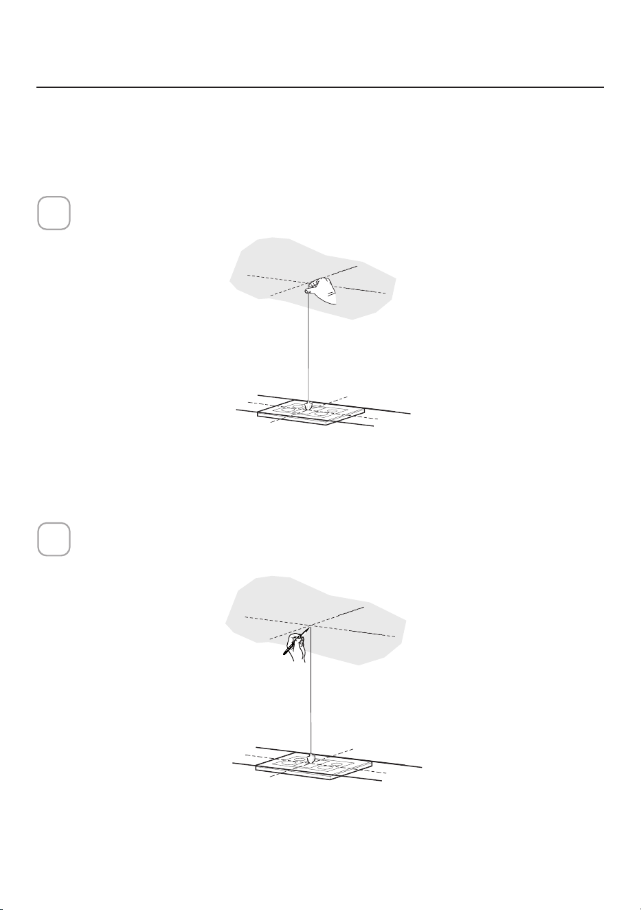
86
Utilice una plomada para marcar el centro de la gama en el techo.
1
PREPARACIÓNDELAINSTALACIÓNDELA
CAMPANADETECHO
Marque el centro.
2
No haga ningún recorte hasta que haya decidido si esta instalación será: sin
conductos y el cableado se ha preparado en función del tipo de soplador.
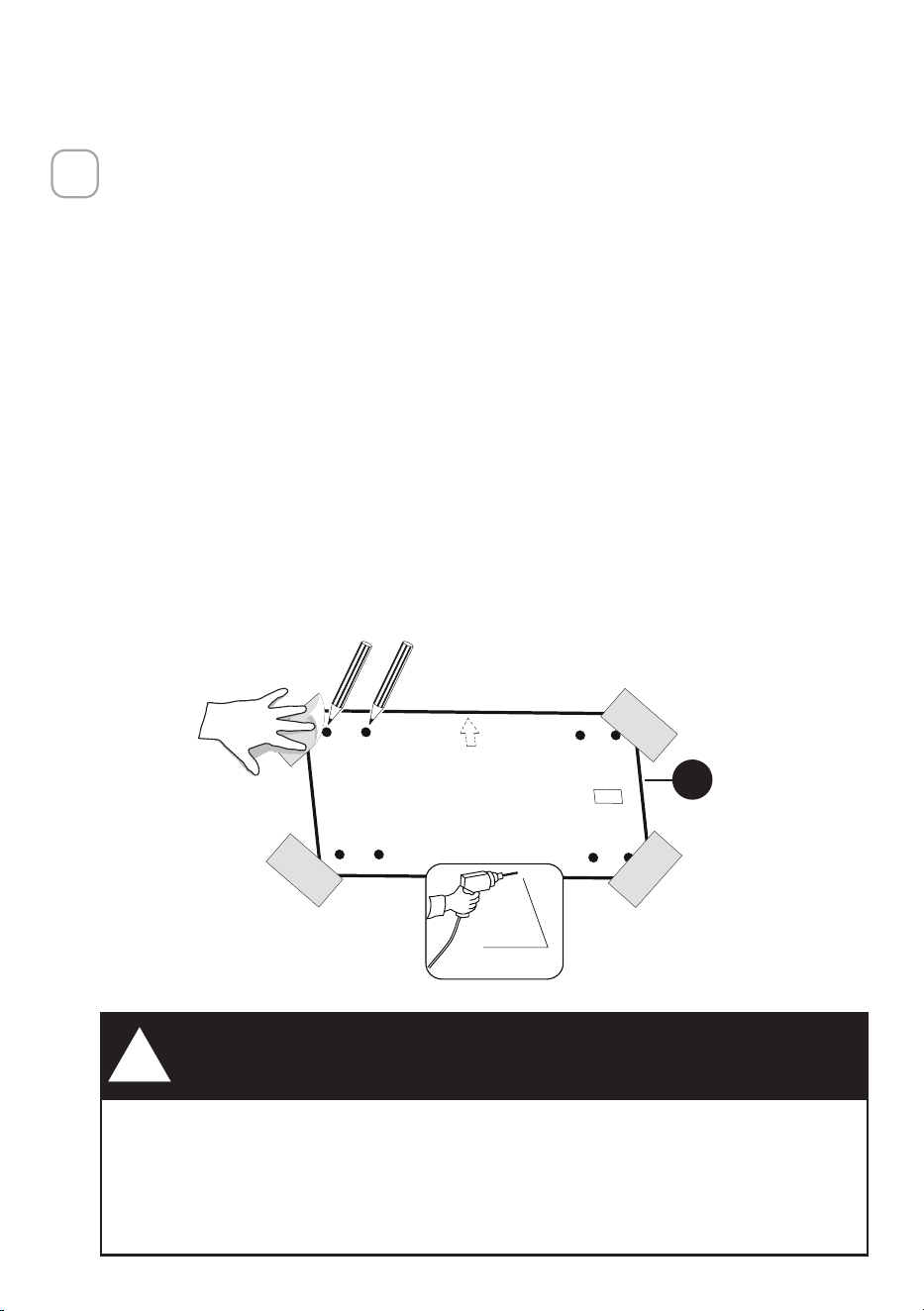
87
H
3/8"
DEBIDO AL TAMAÑO Y AL PESO DE ESTA CAMPANA, EL SOPORTE DEBE
ESTAR FIJAMENTE FIJADO AL TECHO. En el caso de techos de yeso o
de chapa de roca, el soporte debe estar fijado a las viguetas. Si esto no es
posible, debe construirse una estructura de soporte detrás de la escayola
o la chapa de roca. El fabricante no asume ninguna responsabilidad por
lesiones o daños causados por instalaciones inadecuadas.
¡ADVERTENCIA!
!
• Coloque una cubierta gruesa y protectora sobre la placa de cocción para
protegerla de posibles daños o de la suciedad.
• Utilice la plantilla de montaje en el techo para determinar la colocación de
los tornillos de montaje en el techo.
• Marque el centro de los orificios en la plantilla del techo.
• Determine la ubicación adecuada para el cable de alimentación como se
indica en la plantilla.
• Utilice una Broca de 3/8" para hacer este agujero.
• Pase el cable de alimentación. Use calafateo para sellar alrededor del
orificio.
• En la parte superior de la campana extractora hay un orificio para pasar el
cable de alimentación desde el techo.
• No conecte el cable de alimentación a la caja de cableado ni encienda la
campana en este momento.
• Pase suficiente cable de alimentación desde el techo para llegar a la caja
de cableado de la campana.
3

88
OK!
3/16"
OK!
3/16"
OK!
3/16
"
C
INFORMACIÓNSOBRELAINSTALACIÓN
Para preparar la instalación de la campana, oriéntela con el panel de control en la
parte frontal de la campana, tal como se muestra a continuación.
CORRECTO
NO
CORRECTO
Utilice sólo tornillos y piezas pequeñas para apoyar la campana.
Advertencia: De no instalar los tornillos de acuerdo con estas instrucciones,
pueden producirse daños eléctricos.
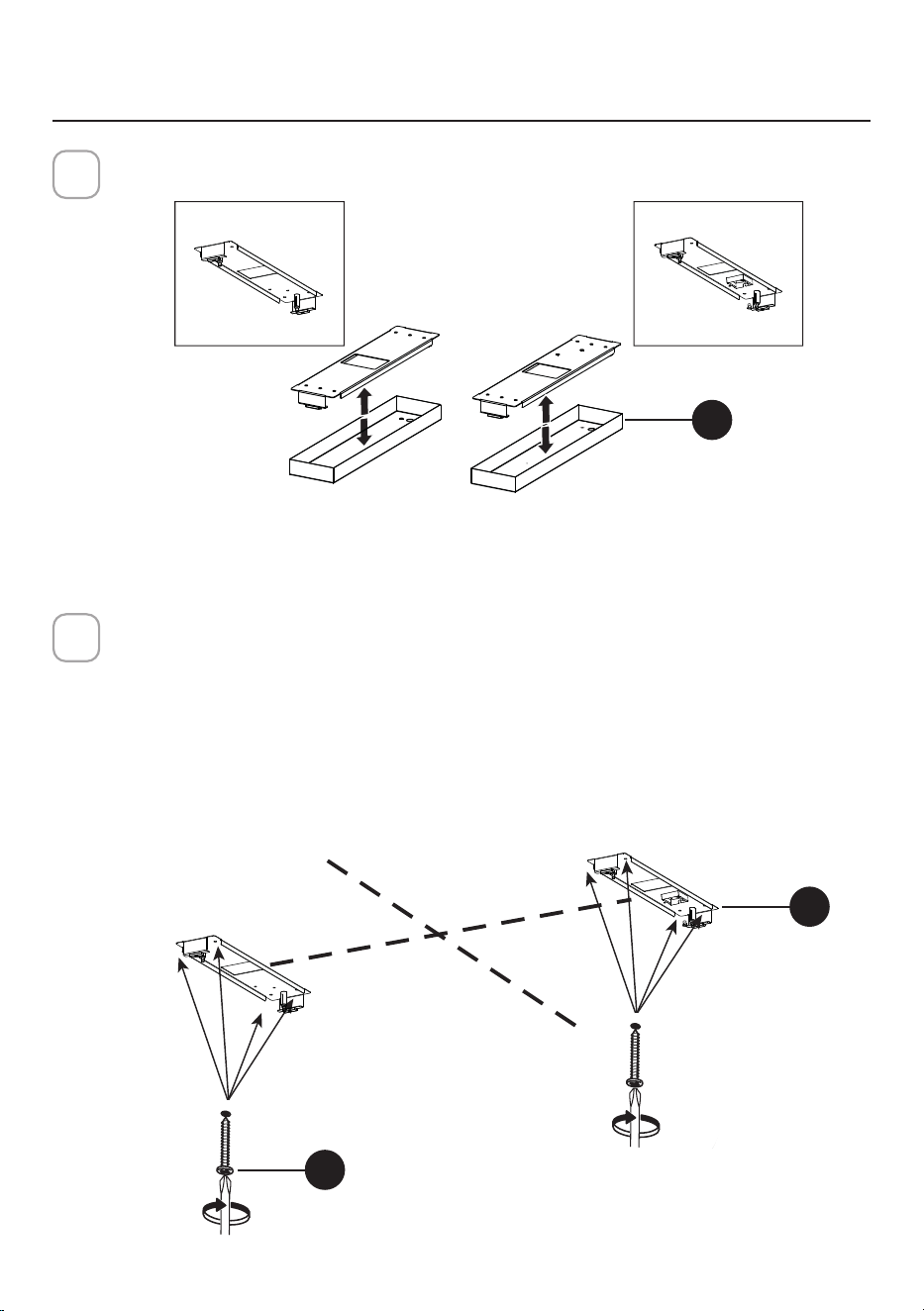
89
INSTALACIÓNDELCUERPODELACAMPANA
EXTRACTORA
Retire la cubierta de los soportes del techo (L).
4
Instalación en el Techo
Utilice los agujeros creados con la plantilla de perforación para la ubicación
de los sujetadores del techo.
Utilice una broca de 5/16" para hacer estos agujeros.
Utilice tacos, si procede, u otros elementos de fijación junto con los elemen-
tos de fijación al techo (adquiridos por separado).
Fije los soportes al techo (L) con los 8 tornillos (C) en los soportes hasta
que estén apretados y seguros.
5
I = 8X
8X
Ø10mm
DXSX
DX
L
Izquierda Derecha
DX
SX
L= 4X
L= 4X
C
L
Izquierda
Derecha

90
Abra el panel de la cubierta del filtro.
El panel de la cubierta del filtro está sujeto por un cierre magnético, tire hacia
abajo con suficiente fuerza para liberarlo como se muestra a continuación.
6
Retirar los filtros de grasa.
7
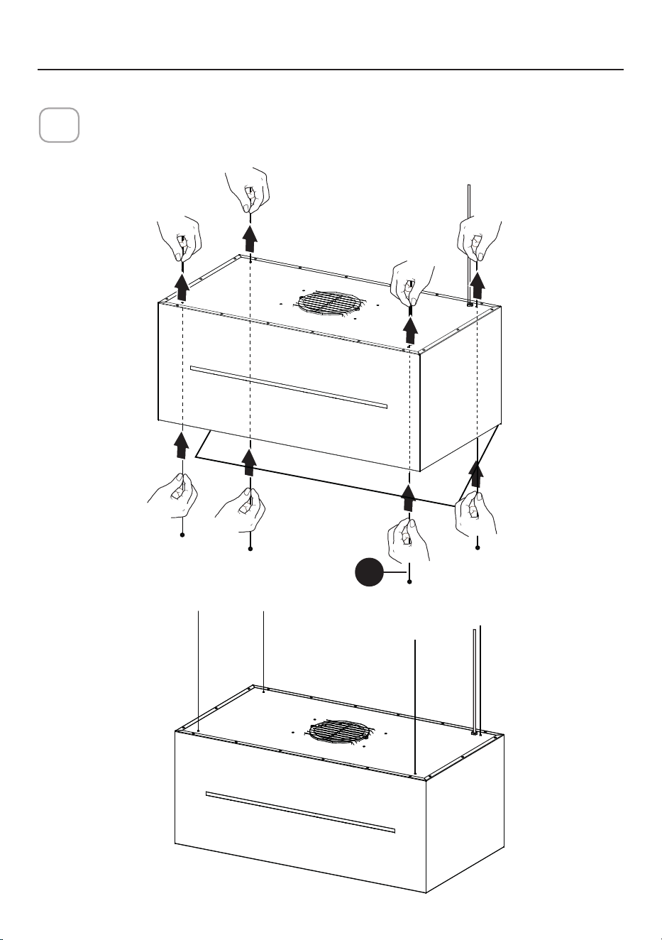
91
I
Introduzca los cables del techo (I) a través de la parte inferior de la
campana extractora y fuera de la parte superior de la campana.
8
INSTRUCCIONESDEMONTAJEENTECHO
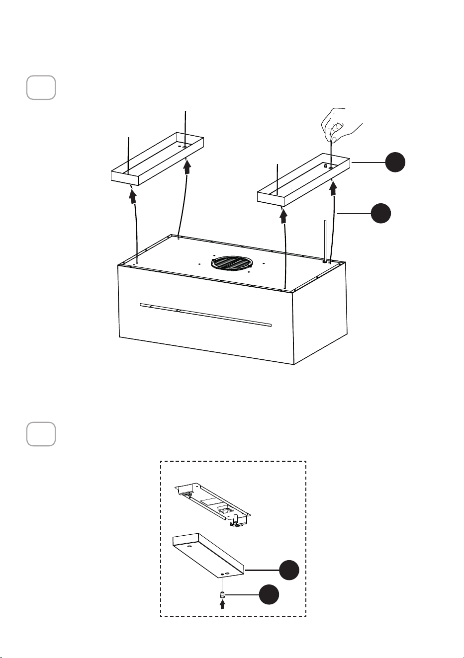
92
4x
DXSX
I
L
Introduzca los cables (I) dentro de los cuatro orificios en las cubiertas del
soporte del techo (L).
9
Introduzca en el enchufe transparente (O) en la cubierta derecha de los
soportes del techo (L).
10
DXSX
O
L
DX
Derecha

93
Introduzca en la cubierta del soporte derecho del techo (L) el Cable de
Suministro de Potencia.
11
L
I = 8X
8X
Ø10mm
DX
SX
DX
Derecha
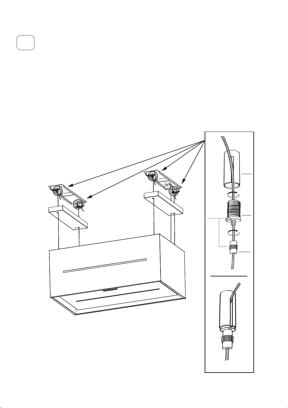
94
4x
A1
B1
C1
D1
4x
CONEXIÓN DE LOS CABLES DE LA PLACA DE LA CAMPANA
¡ATENCIÓN! Antes de continuar con la instalación es necesario mover la
campana a una altura de al menos 30" de la superficie de cocción eléctrica y
de gas, utilizando un soporte o la ayuda de otra persona.
Esto es esencial, ya que los cables de la campana deben conectarse
necesariamente a la placa instalada en el techo sin que el peso de la campana
recaiga sobre la estructura.
El sistema de fijación de los cables se compone de 3 partes:
• Trinquetes Roscados (A1) ya montados en los soportes del techo.
• Tornillos de la abrazadera del cable (B1) suministrados (D1).
• Perillas de seguridad (C1) suministradas (D1).
12
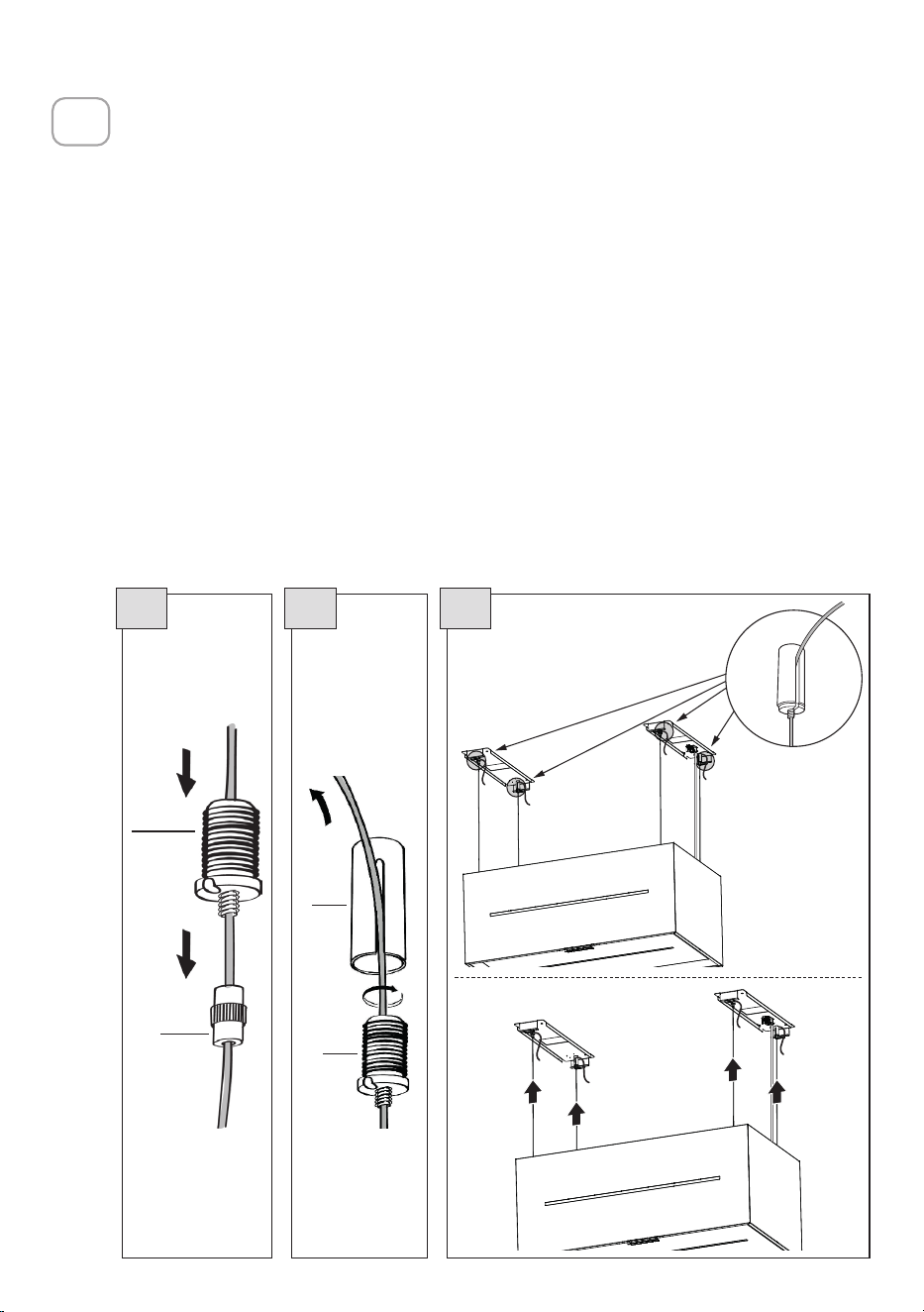
95
B1
C1
15.1 15.2 15.3
A1
B1
CONEXIÓN DE LOS CABLES DE LA PLACA DE LA CAMPANA
MONTAJE DEL CUERPO DE LA CAMPANA
• Introduzca los cables dentro de las perillas de seguridad(C1) con la rosca
hacia arriba (Fig. 15.1).
• Introduzca los cables en los tornillos de la abrazadera del cable (
B1
) (Fig.
15.1).
• Pase los cables por las ranuras de los trinquetes roscados (
A1
) y enrosque
los tornillos de bloqueo del cable (
B1
) en los propios trinquetes (Fig. 15.2).
• Una vez finalizada la operación, el resultado debe ser el mostrado en la
figura para los 4 cables (Fig. 15.3).
• En este punto tenemos los 4 cables conectados a los soportes del techo.
Tensar los cables empujándolos hacia arriba para que se deslicen por el interior
del tornillo de abrazadera del cable y salgan por la ranura del trinquete roscado.
Esto es posible porque el tornillo de abrazadera del cable tiene un sistema que,
si está bien montado, permite que los cables se deslicen en su interior en una
sola dirección, e impide que se deslicen en la otra dirección.
Atención, los cables tienen todos la misma longitud para facilitar la operación
del nivel final. El cable delantero izquierdo no debe estar más flojo que los
demás.
13
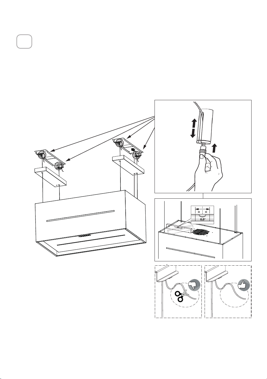
96
4x
1
2
1
2
4x
NIVELACIÓN DE LA CAMPANA
• La campana se nivela ajustando los trinquetes de seguridad.
• Apoye un nivel sobre la campana.
• Al presionar las perillas de seguridad hacia arriba, se "desbloquea" el
movimiento de la campana. Introduciendo o extrayendo el cable del
tornillo de abrazadera del cable se pueden realizar ajustes que permiten
nivelar el cuerpo móvil de la campana.
• Una vez nivelada la campana, hay que volver a apretar las perillas de
seguridad.
14
Advertencia:
• Compruebe que los 4 cables estén estirados.
• Compruebe que los 4 cables no se hayan dañado durante la
instalación.
• NO corte la parte sobrante de cada cable.
• Recuerde que la distancia mínima entre la campana y la placa de
cocción debe ser de 30" de la superficie de cocción eléctrica y de gas.

97
W
INSTALACIÓN DE LOS FILTROS DE CARBÓN VEGETAL
Sólo Recirculación Sin Conducto
• Abra la unidad de iluminación tirando de la muesca prevista para ello.
• Retirar los filtros de grasa.
• Asegúrese de que se han colocado los filtros de carbón activado.
• Consulte también la sección "Mantenimiento".
15
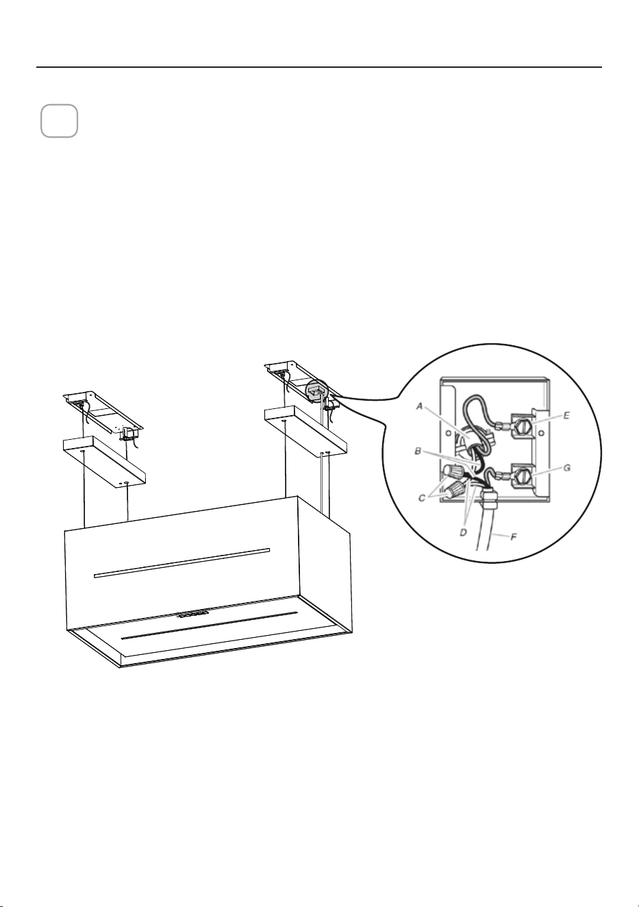
98
Version 02/12 - Page 8
FIGURE 13
MAKE THE ELECTRICAL CONNECTION
Remove the cover from the eld wiring compartment. (SEE
FIGURE 11) DO NOT turn on the power until installation is
complete! Connect the Power Supply Cable to the rangehood.
Connect the Green (Green and Yellow) ground wire under the
Green grounding screw. Attach the White lead of the power
supply to the White lead of the rangehood with a twist-on type
wire connector. Attach the Black lead of the power supply
to the Black lead of the rangehood with a twist-on type wire
connector.
1. The UPPER CHIMNEY
COVER (C in FIGURE 13)
attaches to the top of the
support structure using two
screws provided (G in FIGURE
13). If using the High Ceiling
Chimney Kit, use the UPPER
CHIMNEY COVER supplied
with the kit. Slide up and
attach the UPPER CHIMNEY
COVER.
2. Attach the duct work to the
DAMPER (M in FIGURE 1).
Make sure to seal all joints with
duct tape to prevent leaks.
3. The LOWER CHIMNEY
COVER (B in FIGURE 13)
attaches using two screws
provided (G in FIGURE 13).
Install the LOWER CHIMNEY
COVER by sliding it up over
the support and the UPPER
CHIMNEY COVER.
For ductless installations, line up the DUCTLESS DIVERTER
EXTENSIONS HORIZONTAL (B in FIGURE 12) with the holes
in the LOWER CHIMNEY COVER (D in FIGURE 12) and snap
in the VENT GRIDS (C in FIGURE 12).
INSTALLING THE RANGEHOOD
A. Home power supply cable
B. Black wires
C. UL listed wire connectors
D.White wires
E. Green (or bare) ground wire from home power supply
connected to green ground screw
F. Range hood power supply cable
G.Range hood power supply cable connected to green
ground screw
FIGURE 11
Ductless installations require
a Ductless Conversion
Kit whose components are
pictured in FIGURE 12. Do
not use the DAMPER (M
in FIGURE 1) for ductless
installations. The LOWER
CHIMNEY COVER ( B
in FIGURE 1) should be
discarded and replaced by
the new one with holes from
the Ductless Conversion Kit
(D in FIGURE 12).
As indicated in FIGURE
12, place the DUCTLESS
DIVERTER (A) over the
exhaust opening of the EASY
CUBE (E). Fit the DUCTLESS
DIVERTER EXTENSIONS
HORIZONTAL (B) into the
DIVERTER (A).
FIGURE 12
FOR DUCTLESS INSTALLATIONS
CONEXIONESELÉCTRICAS
Instalación de la conexión del cableado
Retire la tapa del compartimento de cableado de campo.
¡NO conecte la alimentación hasta que la instalación esté completa!
Conecte el Cable de Suministro de Energía a la campana extractora.
Conecte el cable de tierra verde (verde y amarillo) bajo el tornillo de tierra
verde. Conecte el cable Blanco de la fuente de alimentación al cable Blanco
de la campana extractora con un conector de cable de tipo giratorio.
Conecte el cable Negro de la fuente de alimentación al cable Negro de la
campana extractora con un conector de cable de tipo giratorio.
Volver a colocar la tapa del compartimento del cableado de campo y los
filtros de grasa.
16
A. Cable de alimentación de la casa
B. Cables negros
C. Conectores de cables homologados por UL
D. Cables blancos
E. El cable de conexión a tierra verde (o expuesto) de la fuente de
alimentación doméstica debe conectarse al tornillo de tierra verde
F. Cable de alimentación de la campana extractora
G.Cable de alimentación de la campana extractora conectado al tornillo
verde de conexión a tierra.

99
L
R1
P
O1
Inserte el tope (O1) en el cable de alimentación e introdúzcalo todo en la
conexión del cableado.
Cierre la conexión de cableado con la cubierta de terminales (R1) y fíjela con
2 tornillos (P).
17
Sustituya lacubierta de los soportes del techo (L).
18
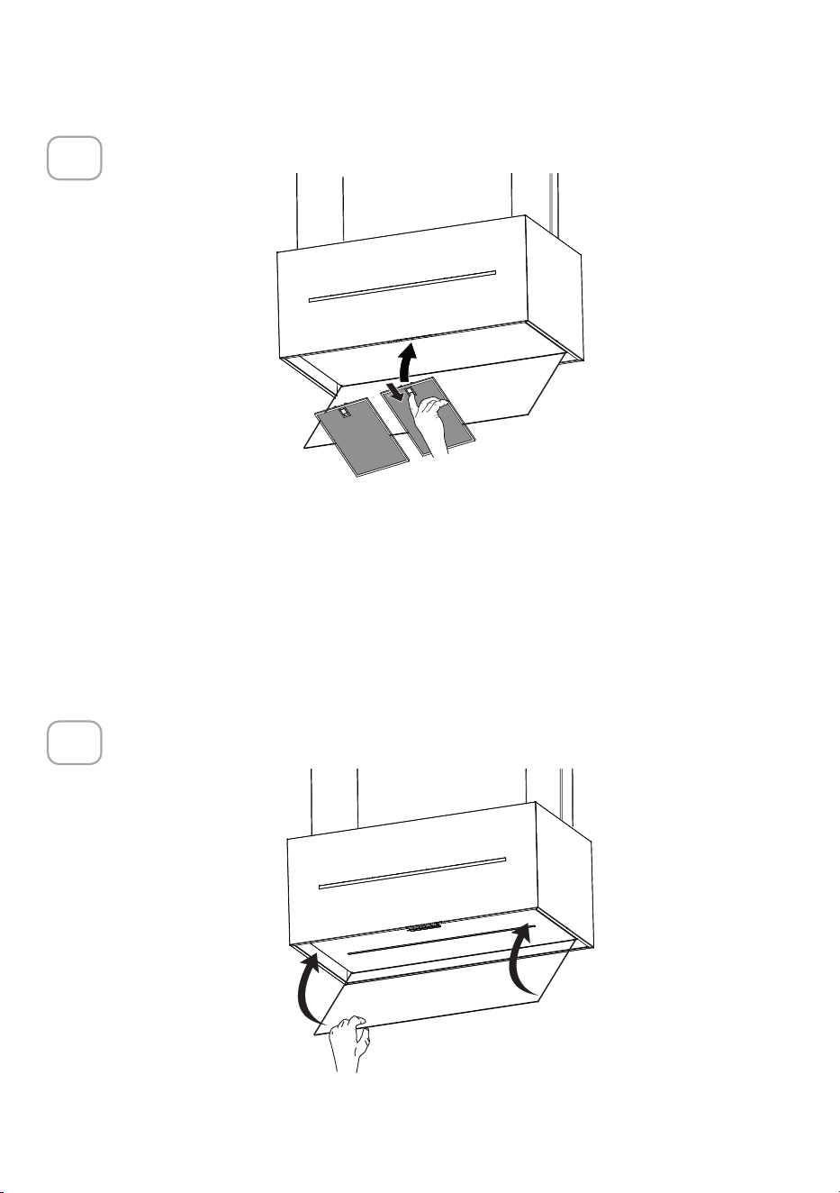
100
Sustituya los filtros de grasa.
19
Cierre el panel de la cubierta del filtro.
20
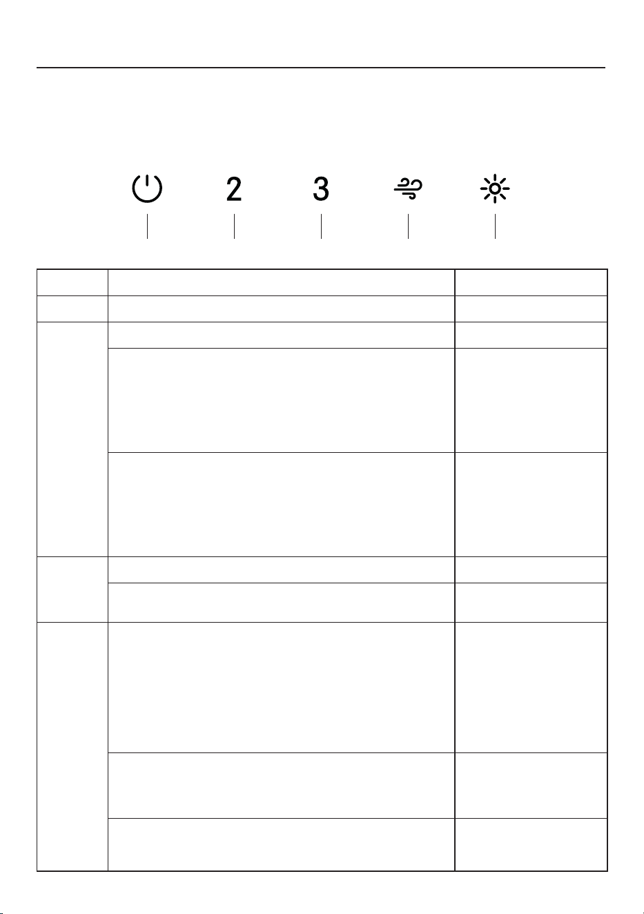
101
A CB D E
OPERACIÓN DE LOS CONTROLES
PARA OBTENER MEJORES RESULTADOS
Ponga en marcha la Campana Extractora varios minutos antes de cocinar para
desarrollar un flujo de aire adecuado. Deje que la Campana Extractora funcione
durante varios minutos después de terminar de cocinar para eliminar todo el humo y
los olores de la cocina.
BOTÓN FUNCIÓN LED
A
Enciende/apaga el motor en la primera velocidad. Fijo.
B
Enciende el motor en la segunda velocidad. A y B fijos.
Pulsación larga cuando la luz está encendida:
Activa/Desactiva la alarma de los Filtros de Carbón
Activados.
Todos los Leds
parpadean dos veces:
alarma activada.
Todos los Leds
parpadean una vez:
alarma desactivada.
Pulsación larga cuando todas las cargas están apagadas
(Motor+Luz):
Activa/Desactiva la función Conexión Wi-Fi.
Nota: la función Wi-Fi se activa automáticamente
cuando el usuario solicita el procedimiento de
configuración Wi-Fi.
Led E Intermitente:
Conexión a la red
doméstica en curso.
Led E fijo: Conexión
Wi-Fi activada.
C
Enciende el motor en la tercera velocidad. A y C fijos.
Pulsación larga cuando el motor está apagado:
La alarma de saturación del Filtro se restablece.
Todos los leds
parpadean 3 veces.
D
Enciende el motor en la velocidad Intensiva.
Esta velocidad está temporizada durante 6 minutos. Al
final del tiempo, el sistema vuelve automáticamente a la
velocidad seleccionada anteriormente. Si se activa con
el motor apagado, una vez transcurrido el tiempo, pasa
al modo APAGADO.
Se desactiva pulsando el mismo botón o apagando el motor.
Intermitente.
Señala la alarma de Filtros Metálicos de Grasa
saturados y la necesidad de lavarlos. La alarma se activa
después de 100 horas de funcionamiento efectivo de la
campana.
Leds B y D
intermitentes.
Señaliza la alarma de saturación del Filtro de Olores
de Carbón Activado. La alarma se activa después de
200 horas de funcionamiento efectivo de la campana.
Leds A y D
parpadeando.
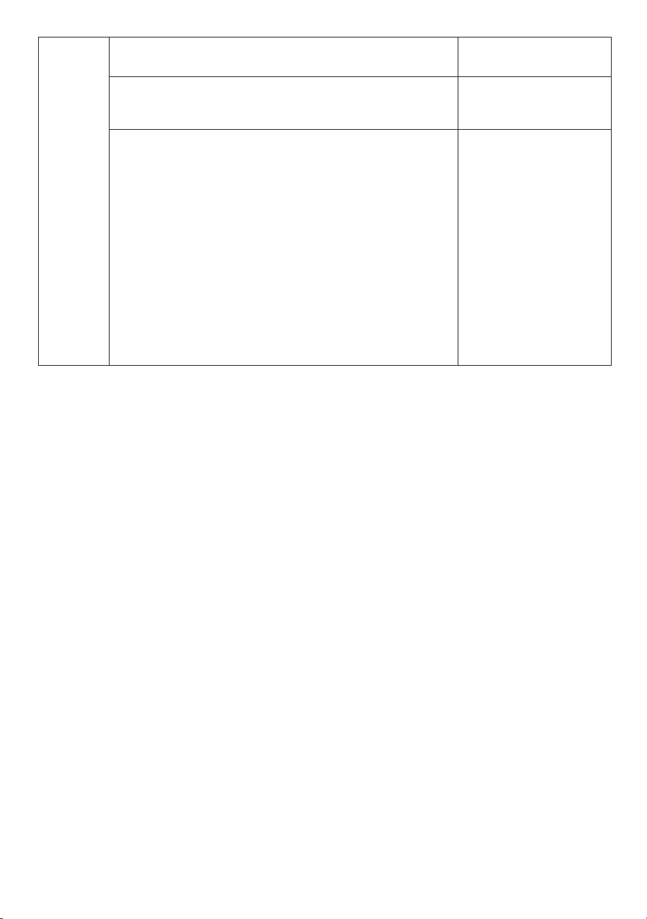
102
E
Pulsación corta: las luces alternan entre intensidad alta,
intensidad media y apagado.
Fijo.
Pulsación larga con todas las cargas encendidas (motor
y luces):
Activa/Desactiva las Luces de Ambiente.
-
Pulsación larga con todas las cargas apagadas (motor
y luces):
Configuración Wi-Fi
Activa/Desactiva el procedimiento de configuración
Wi-Fi.
Antes de iniciar el procedimiento, utilice la Aplicación
Faber Cloud para registrarse en el sistema IOT Faber.
A continuación, siga las instrucciones para añadir un
nuevo dispositivo y registrar el enrutador doméstico.
Si el procedimiento no se completa con éxito en unos
minutos, desactívelo pulsando prolongadamente la tecla
de nuevo y vuelva a intentarlo. No obstante, la campana
abandonará el procedimiento si no se completa con
éxito en 15 minutos.
Leds D y E
intermitentes:
procedimiento de
configuración en curso.
Una vez finalizado con
éxito el procedimiento,
los Leds D y E se
encenderán durante 2
segundos.
103
INFORMACIÓN WI-FI
Este dispositivo cumple con la Parte 15 de las normas FCC. Su funcionamiento
está sujeto a las dos condiciones siguientes: (1) este dispositivo no puede
causar interferencias perjudiciales, y (2) este dispositivo debe aceptar cualquier
interferencia recibida, incluyendo interferencias que puedan causar un
funcionamiento no deseado.
Nota: Este equipo ha sido probado y cumple los límites establecidos para los
dispositivos digitales de Clase B, de acuerdo con la Parte 15 de las Normas de la
FCC. Estos límites están diseñados para proporcionar una protección razonable
contra interferencias perjudiciales en una instalación residencial. Este equipo
genera, utiliza y puede irradiar energía de radiofrecuencia y, si no se instala y utiliza
de acuerdo con las instrucciones, puede causar interferencias perjudiciales en las
comunicaciones por radio. Sin embargo, no hay garantía de que no se produzcan
interferencias en una instalación concreta.
Si este equipo causa interferencias perjudiciales en la recepción de radio o
televisión, lo que puede determinarse apagando y volviendo a encender el equipo,
se invita al usuario a intentar corregir la interferencia tomando una o más de las
siguientes medidas:
• Cambie la orientación o la posición de la antena receptora.
• Aumente la separación entre el equipo y el receptor.
• Conecte el equipo a una toma de corriente de un circuito distinto de aquel
• al que está conectado el receptor.
• Consulte a su distribuidor o a un técnico experto en radio/TV para obtener ayuda.
Las modificaciones de este producto no autorizadas por Faber pueden invalidar la
compatibilidad electromagnética (EMC) y la conformidad inalámbrica y denegar el
permiso de uso del producto.
Este producto demostró la conformidad EMC en condiciones que incluían el uso de
dispositivos periféricos compatibles y cables apantallados entre los componentes
del sistema. Es importante utilizar periféricos conformes y cables blindados entre
los componentes del sistema para reducir la posibilidad de causar interferencias en
radios, televisores y otros dispositivos electrónicos.
Exposición a energía de radiofrecuencia. La potencia de salida radiada de este
dispositivo cumple los límites de exposición a radiofrecuencias de la FCC e IC. Este
dispositivo debe utilizarse con una distancia mínima de separación de 20 cm (8
pulgadas) entre el equipo y el cuerpo de una persona.
Información sobre el Aparato Conectado
Contiene FCC ID: 2AC7Z-ESPS3WROOM1
Contiene IC: 21098-ESPS3WROOM1
Modelo: ESP32-S3-WROOM-1
CAN ICES-003(B)/NMB-003(B)
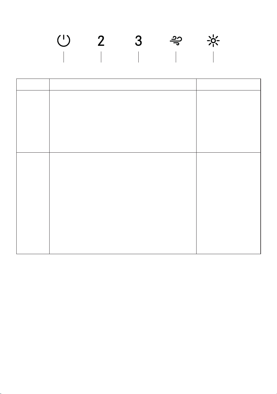
104
A CB D E
CONEXIONES WI-FI
BOTÓN FUNCIÓN LED
B
Activar / Desactivar la función de Conexión Wi-Fi.
Una pulsación larga del botón de velocidad 2 con el
motor y las luces apagadas para activar / desactivar
el WI-FI.
Nota: la función Wi-Fi se activa automáticamente
cuando el usuario solicita el procedimiento de
configuración Wi-Fi.
Leds D + E
parpadeando:
Conexión al
enrutador inalámbrico
doméstico en curso.
Leds D + E fijos:
Conexión Wi-Fi
activada.
E
Inicio de la configuración Wi-Fi
Una pulsación larga con el motor y las luces
Apagadas para Entrar o Finalizar el procedimiento de
configuración Wi-Fi. Antes de iniciar el procedimiento,
utilice la Aplicación Faber Cloud para registrarse
en el sistema IOT Faber. A continuación, siga las
instrucciones para añadir un nuevo dispositivo y
registrar su enrutador inalámbrico doméstico.
Si el procedimiento no se completa con éxito en
unos minutos, detenga el proceso de configuración
manteniendo pulsado el botón intensivo durante
3 segundos. Mantenga pulsado el botón de nuevo
durante 3 segundos para iniciar el proceso. La
campana detendrá el proceso de configuración Wi-fi
si no se completa con éxito en 15 minutos.
Leds D + E fijos:
La configuración está
en curso.
Leds D + E:
Cuando la
configuración
ha finalizado, los
leds permanecen
encendidos durante 2
segundos.
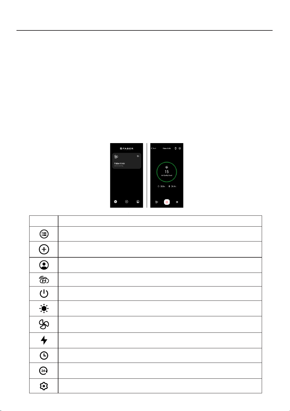
105
5. FABER CLOUD APP
The Faber Cloud App is available for
iOS and Android smartphones and al-
lows remote access to all hood func-
tions.
Icon Function
Home page
Add new device
User profile management
Connected to Faber Wi-Fi network
Hood on/off
Lighting system management
Motor speed management
Intensive Function
24h Function
Delay Function
Automatic Function
App settings management
6. REMOTE CONTROL
• This appliance can be controlled us-
ing a remote control.
• ATTENTION: before proceeding, ac-
tivate K-Link Mode on the remote
control (see the device manual for
further details).
7. LIGHTING
• Please contact the Service Depart-
ment to change it ("Please contact
the service department to purchase
it").
8
APLICACIÓN FABER CLOUD
Aplicación Faber Cloud
Su campana extractora es compatible con la aplicación Faber Cloud. Todo lo que
necesita es una red Wi-Fi conectada a Internet que esté dentro del alcance de la
campana extractora. Puedes controlar todas las funciones de tu campana extractora
desde cualquier lugar utilizando un dispositivo móvil o tu altavoz inteligente Amazon
Alexa o Google Home. Cuando está conectado a su altavoz inteligente, puede controlar
su campana con su voz.
La aplicación Faber Cloud está disponible en dispositivos iOS con iOS 11.0 o posterior
o en dispositivos Android con Android versión 8 o posterior. Visite Apple App Store
o Google Play Store para obtener más información. Su campana extractora tendrá
plena funcionalidad si no está utilizando las funciones Wi-fi o la aplicación Faber Cloud,
ninguna de ellas es necesaria.
Consulte la Guía de Inicio de Conexión Rápida incluida para obtener más información.
Icono Función
5. FABER CLOUD APP
The Faber Cloud App is available for
iOS and Android smartphones and al-
lows remote access to all hood func-
tions.
Icon Function
Home page
Add new device
User profile management
Connected to Faber Wi-Fi network
Hood on/off
Lighting system management
Motor speed management
Intensive Function
24h Function
Delay Function
Automatic Function
App settings management
6. REMOTE CONTROL
• This appliance can be controlled us-
ing a remote control.
• ATTENTION: before proceeding, ac-
tivate K-Link Mode on the remote
control (see the device manual for
further details).
7. LIGHTING
• Please contact the Service Depart-
ment to change it ("Please contact
the service department to purchase
it").
8
Página de inicio
5. FABER CLOUD APP
The Faber Cloud App is available for
iOS and Android smartphones and al-
lows remote access to all hood func-
tions.
Icon Function
Home page
Add new device
User profile management
Connected to Faber Wi-Fi network
Hood on/off
Lighting system management
Motor speed management
Intensive Function
24h Function
Delay Function
Automatic Function
App settings management
6. REMOTE CONTROL
• This appliance can be controlled us-
ing a remote control.
• ATTENTION: before proceeding, ac-
tivate K-Link Mode on the remote
control (see the device manual for
further details).
7. LIGHTING
• Please contact the Service Depart-
ment to change it ("Please contact
the service department to purchase
it").
8
Añadir nuevo dispositivo
5. FABER CLOUD APP
The Faber Cloud App is available for
iOS and Android smartphones and al-
lows remote access to all hood func-
tions.
Icon Function
Home page
Add new device
User profile management
Connected to Faber Wi-Fi network
Hood on/off
Lighting system management
Motor speed management
Intensive Function
24h Function
Delay Function
Automatic Function
App settings management
6. REMOTE CONTROL
• This appliance can be controlled us-
ing a remote control.
• ATTENTION: before proceeding, ac-
tivate K-Link Mode on the remote
control (see the device manual for
further details).
7. LIGHTING
• Please contact the Service Depart-
ment to change it ("Please contact
the service department to purchase
it").
8
Gestión del perfil de usuario
5. FABER CLOUD APP
The Faber Cloud App is available for
iOS and Android smartphones and al-
lows remote access to all hood func-
tions.
Icon Function
Home page
Add new device
User profile management
Connected to Faber Wi-Fi network
Hood on/off
Lighting system management
Motor speed management
Intensive Function
24h Function
Delay Function
Automatic Function
App settings management
6. REMOTE CONTROL
• This appliance can be controlled us-
ing a remote control.
• ATTENTION: before proceeding, ac-
tivate K-Link Mode on the remote
control (see the device manual for
further details).
7. LIGHTING
• Please contact the Service Depart-
ment to change it ("Please contact
the service department to purchase
it").
8
Conectado a la red Wi-Fi de Faber
5. FABER CLOUD APP
The Faber Cloud App is available for
iOS and Android smartphones and al-
lows remote access to all hood func-
tions.
Icon Function
Home page
Add new device
User profile management
Connected to Faber Wi-Fi network
Hood on/off
Lighting system management
Motor speed management
Intensive Function
24h Function
Delay Function
Automatic Function
App settings management
6. REMOTE CONTROL
• This appliance can be controlled us-
ing a remote control.
• ATTENTION: before proceeding, ac-
tivate K-Link Mode on the remote
control (see the device manual for
further details).
7. LIGHTING
• Please contact the Service Depart-
ment to change it ("Please contact
the service department to purchase
it").
8
Encendido/apagado de la campana
5. FABER CLOUD APP
The Faber Cloud App is available for
iOS and Android smartphones and al-
lows remote access to all hood func-
tions.
Icon Function
Home page
Add new device
User profile management
Connected to Faber Wi-Fi network
Hood on/off
Lighting system management
Motor speed management
Intensive Function
24h Function
Delay Function
Automatic Function
App settings management
6. REMOTE CONTROL
• This appliance can be controlled us-
ing a remote control.
• ATTENTION: before proceeding, ac-
tivate K-Link Mode on the remote
control (see the device manual for
further details).
7. LIGHTING
• Please contact the Service Depart-
ment to change it ("Please contact
the service department to purchase
it").
8
Gestión del sistema de iluminación
5. FABER CLOUD APP
The Faber Cloud App is available for
iOS and Android smartphones and al-
lows remote access to all hood func-
tions.
Icon Function
Home page
Add new device
User profile management
Connected to Faber Wi-Fi network
Hood on/off
Lighting system management
Motor speed management
Intensive Function
24h Function
Delay Function
Automatic Function
App settings management
6. REMOTE CONTROL
• This appliance can be controlled us-
ing a remote control.
• ATTENTION: before proceeding, ac-
tivate K-Link Mode on the remote
control (see the device manual for
further details).
7. LIGHTING
• Please contact the Service Depart-
ment to change it ("Please contact
the service department to purchase
it").
8
Gestión de la velocidad del motor
5. FABER CLOUD APP
The Faber Cloud App is available for
iOS and Android smartphones and al-
lows remote access to all hood func-
tions.
Icon Function
Home page
Add new device
User profile management
Connected to Faber Wi-Fi network
Hood on/off
Lighting system management
Motor speed management
Intensive Function
24h Function
Delay Function
Automatic Function
App settings management
6. REMOTE CONTROL
• This appliance can be controlled us-
ing a remote control.
• ATTENTION: before proceeding, ac-
tivate K-Link Mode on the remote
control (see the device manual for
further details).
7. LIGHTING
• Please contact the Service Depart-
ment to change it ("Please contact
the service department to purchase
it").
8
Función Intensiva
5. FABER CLOUD APP
The Faber Cloud App is available for
iOS and Android smartphones and al-
lows remote access to all hood func-
tions.
Icon Function
Home page
Add new device
User profile management
Connected to Faber Wi-Fi network
Hood on/off
Lighting system management
Motor speed management
Intensive Function
24h Function
Delay Function
Automatic Function
App settings management
6. REMOTE CONTROL
• This appliance can be controlled us-
ing a remote control.
• ATTENTION: before proceeding, ac-
tivate K-Link Mode on the remote
control (see the device manual for
further details).
7. LIGHTING
• Please contact the Service Depart-
ment to change it ("Please contact
the service department to purchase
it").
8
Función de Retraso
5. FABER CLOUD APP
The Faber Cloud App is available for
iOS and Android smartphones and al-
lows remote access to all hood func-
tions.
Icon Function
Home page
Add new device
User profile management
Connected to Faber Wi-Fi network
Hood on/off
Lighting system management
Motor speed management
Intensive Function
24h Function
Delay Function
Automatic Function
App settings management
6. REMOTE CONTROL
• This appliance can be controlled us-
ing a remote control.
• ATTENTION: before proceeding, ac-
tivate K-Link Mode on the remote
control (see the device manual for
further details).
7. LIGHTING
• Please contact the Service Depart-
ment to change it ("Please contact
the service department to purchase
it").
8
Función 24H
5. FABER CLOUD APP
The Faber Cloud App is available for
iOS and Android smartphones and al-
lows remote access to all hood func-
tions.
Icon Function
Home page
Add new device
User profile management
Connected to Faber Wi-Fi network
Hood on/off
Lighting system management
Motor speed management
Intensive Function
24h Function
Delay Function
Automatic Function
App settings management
6. REMOTE CONTROL
• This appliance can be controlled us-
ing a remote control.
• ATTENTION: before proceeding, ac-
tivate K-Link Mode on the remote
control (see the device manual for
further details).
7. LIGHTING
• Please contact the Service Depart-
ment to change it ("Please contact
the service department to purchase
it").
8
Gestión de los ajustes de la aplicación

106
CONTROL REMOTO
El aparato puede controlarse con un mando a distancia alimentado por pilas alcalinas
de carbono-zinc de 1,5 V del tipo estándar LR03-AAA (no incluidas).
• Las pilas usadas deben desecharse de forma adecuada.
Precaución:
• No ponga el mando a distancia
cerca de las fuentes de calor.
• No deseche las pilas con la basura
normal, deben depositarse en los
contenedores especícos.
Limpieza de las Superficies Exteriores:
Por favor, tenga en cuenta que los abrasivos y los agentes de fregado pueden rayar
los acabados de la campana extractora y no deben utilizarse para limpiar las supercies
acabadas.
LIMPIEZA DEL ACERO INOXIDABLE

107
FILTRODEGRASA
Los ltros deben limpiarse cada 2 meses de funcionamiento, o con mayor frecuencia
en caso de uso intensivo, y pueden lavarse en el lavavajillas.
LIMPIEZADELFILTRODEGRASA
METÁLICO AUTO-SOPORTE
• Abra el panel de la cubierta del ltro.
• Retire el ltro uno a uno empujándolo hacia
la parte trasera de la campana extractora
y tirando simultáneamente hacia abajo.
• Evite doblar el ltro al lavarlo. Antes de
volver a colocarlo en la campana, asegúrese
de que esté completamente seco.
• Cuando coloque el ltro en la campana,
asegúrese de que está montado en la
posición correcta, con el asa hacia fuera.
• Vuelva a colocar la tapa del ltro.
• No debe haber agua en el ltro antes de
instalarlo.
MANTENIMIENTO
FILTRO DE CARBÓN ACTIVADO
No se puede lavar ni regenerar, y debe
cambiarse aproximadamente cada 4 meses,
o con mayor frecuencia en caso de uso
especialmente intensivo.
Cambio
• Abra el panel de la cubierta del filtro.
• Retire el filtro de grasa.
• Retire los Filtros de Carbón Activado
saturados.
• Coloque los nuevos Filtros.
• Vuelva a colocar el filtro anti-grasa y el
panel de la cubierta del filtro.

108
SUSTITUCIÓNDELAILUMINACIÓN
Las luces LED deben ser sustituidas por el servicio técnico autorizado de Faber.

109
DIAGRAMADECABLEADO
0 1 2 3 4 5 6 7 8 9
H90_1144
01
Drawing N : Rev :
Modif. by
These drawings and specifications are the property of Franke Technology and
Trademartk Ltd and shall not be reproduced.copied or trasferred to any third party
without the prior written permission of Franke Tecnology and Trandemark Ltd.
Switzerland.It is strictly prohibited to get quotes from the drawing or bring
modifications without the prior written conset of franke Techology and Trademark
Doc.status
Modification description
Approved date
WIRING DIAGR.M8-4V CHA LED WI-FI STS/EXTERNAL
Approved by
Denomination
Doc Type
Creation date
14/10/2024
FABER Corrado
Created by
991.0724.314
Code
USER INTERFACE
CHL
PIN 3
PIN 1
PIN 3
PIN 1
PIN 9
PIN 7
PIN 9
PIN 7
1 2
LED BAR
1 2
1
2
3
4
5
6
7
1
2
3
4
L N
110-127V 60HZ
21
21
21
21
1 2
LED BAR
1 2
1 2
LED BAR
1 2
BRW
L-B
PNK
BLU
WHT
GRY
BLK
RED
M8-4V
BRW
ORG
BLK
GRY
WHT
BLU
BLK
GRY
BLK
GRY
BLU
RED
BLK
BLK
GRY
GRY
BLK

110
GARANTÍA
Franke Home Solutions Warranty for Franke and Faber Branded Product
Effective March 1, 2022
In the United States, Canada and Latin America, Franke warrants the Faber branded products from manufacturing defects
in material and workmanship when purchased from a Franke or Faber Authorized Retailer pursuant to product-specific
warranties detailed herein (each, a “Warranty” and collectively, the “Warranties”). The products must be properly installed,
per Franke’s installation instructions, in their original installation, and used in normal indoor residential kitchen
applications. Any products or components which have been modified or altered from their original intended condition will
void the Warranty. The Franke Warranties for Faber branded products are limited to the original purchaser and are non-
transferrable. These Warranties do not include products purchased from non-Authorized Retailers, products that are
obsolete or discontinued, or products that were previous display models. All issues with installed products are considered
warranty claims and not subject to the Return Policy. Franke reserves the right to inspect any Franke / Faber product
reported to be defective pursuant to a Warranty claim and the original installation prior to providing a replacement product
and/or component. All decisions are final. In no situation shall the liability of Franke exceed the amount of the original
purchase price.
The Warranties do not cover, and Franke shall not be liable for, any damage to products or components resulting from
misuse or abuse, accidental damages, normal wear such as scuffs, scratches or finish reduction/fading, improper
installation, abnormal usage, negligence, damage caused by improper maintenance or cleaning. Damage caused by
impurities, corrosive chemicals or acts beyond Franke’s control are not covered by any Warranty. Service calls to correct
the installation of a range hood, instructions on how to operate a range hood, to replace or repair house fuses or to correct
house wiring or plumbing are not covered by any Warranty. Service calls to repair or replace range hood light bulbs, fuses
or filters and these consumable part costs are also excluded from Warranty coverage. Installation not in accordance with
electrical or plumbing codes or Franke / Faber documentation are not covered by any Warranty. Replacement parts or
repair labor costs for units operated outside the United States, Canada or Latin America, including any non-UL or C-UL or
non-NOM approved Franke / Faber range hoods are excluded from Warranty coverage. Expenses for travel and
transportation for service in remote locations and pickup and delivery charges are not covered by any Warranty. Franke /
Faber range hoods should always be serviced in the home in their original installation.
Franke / Faber product replacements do not include liability for project delays. Product replacements are not guaranteed
to be exact replacements. If the original product is not available at the time of the warranty claim, at Franke’s option, the
product replacements will be of similar size, material, and value. Any products or components which have been modified
or altered, from its original intended condition will void the warranty.
The Warranties do not allow recovery of incidental or consequential damages such as loss of use, delay, property
damage or other consequential damage, and Franke accepts no liability for such damages. Each Warranty is limited to
the conditions set forth herein and to the applicable warranty period specified herein and is exclusive. EXCEPT FOR THE
WARRANTIES SET FORTH HEREIN, FRANKE MAKES NO WARRANTY WHATSOEVER WITH RESPECT TO THE
PRODUCTS, INCLUDING, BUT NOT LIMITED TO, (1) ANY WARRANTY OF MERCHANTABILITY, (2) WARRANTY OF
FITNESS FOR A PARTICULAR PURPOSE, (3) WARRANTY OF TITLE, OR (4) WARRANTY AGAINST INFRINGEMENT
OF INTELLECTUAL PROPERTY RIGHTS OF A THIRD PARTY, WHETHER EXPRESS OR IMPLIED BY LAW, COURSE
OF DEALING, COURSE OF PERFORMANCE, USAGE OF TRADE OR OTHERWISE. LEGAL DISCLAIMER PLEASE
READ CAREFULLY. Franke Kitchen Systems LLC provides the above information to you as a public service to our
customers. By accessing and using this information, you agree to the following and to comply with all applicable laws. If
you do not agree with these terms and conditions, do not use this information. While we try to keep the information
current, changes may have occurred since its creation. Contact your Regional Manager or Customer Service to verify
information regarding Franke Kitchen Systems LLC programs and their use by you.
Franke / Faber Range Hood Limited Warranty:
Franke / Faber range hoods are warranted against any defect in materials or workmanship for the original purchaser for a
period of two (2) years from the date of original purchase when used in standard residential indoor applications. This
warranty covers labor and replacement parts. Franke, at its option, may repair or replace the product or components
necessary to restore the product to good working condition.
La garantía de Franke Home Solutions para los productos de las marcas Franke y Faber entra en vigor el 1 de marzo de 2022
En Estados Unidos, Canadá y América Latina, Franke garantiza los productos de la marca Faber contra defectos de fabricación
en materiales y mano de obra cuando se compran a un minorista autorizado de Franke o Faber de acuerdo con las garantías
específicas del producto que se detallan en este documento (cada una, una "Garantía" y colectivamente, las "Garantías"). Los
productos deben ser instalados correctamente, según las instrucciones de instalación de Franke, en su instalación original,
y utilizados en aplicaciones normales de cocina residencial en interiores. Cualquier producto o componente que haya sido
modificado o alterado de su condición original anulará la garantía. Las garantías de Franke para los productos de la marca Faber
están limitadas al comprador original y no son transferibles. Estas garantías no incluyen los productos comprados a minoristas no
autorizados, los productos obsoletos o descatalogados, ni los productos que eran modelos de exposición anteriores. Todos los
problemas con los productos instalados se consideran reclamaciones de garantía y no están sujetos a la política de devoluciones.
Franke se reserva el derecho de inspeccionar cualquier producto Franke / Faber reportado como defectuoso en virtud de una
reclamación de garantía y la instalación original antes de proporcionar un producto y/o componente de reemplazo. Todas las
decisiones son definitivas. En ningún caso la responsabilidad de Franke superará el importe del precio de compra original.
Las garantías no cubren, y Franke no será responsable, de ningún daño a los productos o componentes derivado de un mal uso
o abuso, daños accidentales, desgaste normal como rozaduras, arañazos o reducción/descoloramiento del acabado, instalación
incorrecta, uso anormal, negligencia, daños causados por un mantenimiento o limpieza inadecuados. Los daños causados por
impurezas, productos químicos corrosivos o actos fuera del control de Franke no están cubiertos por ninguna garantía. Las
llamadas de servicio para corregir la instalación de una campana extractora, las instrucciones sobre el funcionamiento de una
campana extractora, para sustituir o reparar los fusibles de la casa o para corregir el cableado o la fontanería de la casa no están
cubiertas por ninguna Garantía. Las llamadas de servicio para reparar o sustituir las bombillas, fusibles o filtros de la campana
extractora, así como los costes de estas piezas consumibles, también están excluidos de la cobertura de la garantía. La instalación
que no esté de acuerdo con los códigos eléctricos o de fontanería o con la documentación de Franke / Faber no está cubierta
por ninguna garantía. Los costes de las piezas de repuesto o de la mano de obra de reparación de las unidades utilizadas fuera
de los Estados Unidos, Canadá o América Latina, incluidas las campanas extractoras de cocina Franke / Faber no aprobadas por
la norma UL o C-UL, están excluidos de la cobertura de la garantía. Los gastos de viaje y transporte para el servicio en lugares
remotos y los gastos de recogida y entrega no están cubiertos por ninguna Garantía. Las campanas extractoras Franke / Faber
siempre deben ser revisadas en el hogar en su instalación original.
Las sustituciones de productos Franke / Faber no incluyen la responsabilidad por los retrasos del proyecto. No se garantiza que
las sustituciones de los productos sean exactas. Si el producto original no está disponible en el momento de la reclamación de
la garantía, a opción de Franke, los reemplazos del producto serán de tamaño, material y valor similares. Cualquier producto o
componente que haya sido modificado o alterado de su condición original anulará la garantía.
Las garantías no permiten la recuperación de los daños incidentales o indirectos, como la pérdida de uso, el retraso, los daños a la
propiedad u otros daños indirectos, y Franke no acepta ninguna responsabilidad por tales daños. Cada Garantía está limitada a las
condiciones establecidas en el presente documento y al período de garantía aplicable especificado en el mismo y es exclusiva. A
EXCEPCIÓN DE LAS GARANTÍAS ESTABLECIDAS EN ESTE DOCUMENTO, FRANKE NO OFRECE NINGUNA GARANTÍA CON
RESPECTO A LOS PRODUCTOS, INCLUYENDO, PERO NO LIMITADO A, (1) CUALQUIER GARANTÍA DE COMERCIALIZACIÓN,
(2) LA GARANTÍA DE IDONEIDAD PARA UN PROPÓSITO PARTICULAR, (3) LA GARANTÍA DE TÍTULO, O (4) LA GARANTÍA
CONTRA LA VIOLACIÓN DE LOS DERECHOS DE PROPIEDAD INTELECTUAL DE UN TERCERO, YA SEA EXPRESA O
IMPLÍCITA POR LA LEY, EL DESARROLLO DE LOS NEGOCIOS, EL DESARROLLO DE LA EJECUCIÓN, EL USO DEL COMERCIO
O DE OTRA MANERA. AVISO LEGAL POR FAVOR
LEA ATENTAMENTE. Franke Kitchen Systems LLC le proporciona la información anterior como un servicio público a nuestros
clientes. Al acceder y utilizar esta información, usted acepta lo siguiente y el cumplimiento de todas las leyes aplicables. Si no está
de acuerdo con estas condiciones, no utilice esta información. Aunque intentamos mantener la información actualizada, pueden
haberse producido cambios desde su creación. Póngase en contacto con su gerente regional o con el servicio de atención al
cliente para verificar la información relativa a los programas de Franke Kitchen Systems LLC y su uso.
Garantía limitada de la campana extractora Franke / Faber:
Las campanas extractoras de Franke / Faber están garantizadas contra cualquier defecto de materiales o mano de obra
para el comprador original durante un período de dos (2) años a partir de la fecha de compra original cuando se utilizan en
aplicaciones residenciales estándar de interior. Esta garantía cubre la mano de obra y las piezas de recambio. Franke, a su elección,
puede reparar o sustituir el producto o los componentes necesarios para restablecer el producto en buenas condiciones de
funcionamiento.
111
Franke Home Solutions Warranty for Franke and Faber Branded Product
Effective March 1, 2022
In the United States, Canada and Latin America, Franke warrants the Faber branded products from manufacturing defects
in material and workmanship when purchased from a Franke or Faber Authorized Retailer pursuant to product-specific
warranties detailed herein (each, a “Warranty” and collectively, the “Warranties”). The products must be properly installed,
per Franke’s installation instructions, in their original installation, and used in normal indoor residential kitchen
applications. Any products or components which have been modified or altered from their original intended condition will
void the Warranty. The Franke Warranties for Faber branded products are limited to the original purchaser and are non-
transferrable. These Warranties do not include products purchased from non-Authorized Retailers, products that are
obsolete or discontinued, or products that were previous display models. All issues with installed products are considered
warranty claims and not subject to the Return Policy. Franke reserves the right to inspect any Franke / Faber product
reported to be defective pursuant to a Warranty claim and the original installation prior to providing a replacement product
and/or component. All decisions are final. In no situation shall the liability of Franke exceed the amount of the original
purchase price.
The Warranties do not cover, and Franke shall not be liable for, any damage to products or components resulting from
misuse or abuse, accidental damages, normal wear such as scuffs, scratches or finish reduction/fading, improper
installation, abnormal usage, negligence, damage caused by improper maintenance or cleaning. Damage caused by
impurities, corrosive chemicals or acts beyond Franke’s control are not covered by any Warranty. Service calls to correct
the installation of a range hood, instructions on how to operate a range hood, to replace or repair house fuses or to correct
house wiring or plumbing are not covered by any Warranty. Service calls to repair or replace range hood light bulbs, fuses
or filters and these consumable part costs are also excluded from Warranty coverage. Installation not in accordance with
electrical or plumbing codes or Franke / Faber documentation are not covered by any Warranty. Replacement parts or
repair labor costs for units operated outside the United States, Canada or Latin America, including any non-UL or C-UL or
non-NOM approved Franke / Faber range hoods are excluded from Warranty coverage. Expenses for travel and
transportation for service in remote locations and pickup and delivery charges are not covered by any Warranty. Franke /
Faber range hoods should always be serviced in the home in their original installation.
Franke / Faber product replacements do not include liability for project delays. Product replacements are not guaranteed
to be exact replacements. If the original product is not available at the time of the warranty claim, at Franke’s option, the
product replacements will be of similar size, material, and value. Any products or components which have been modified
or altered, from its original intended condition will void the warranty.
The Warranties do not allow recovery of incidental or consequential damages such as loss of use, delay, property
damage or other consequential damage, and Franke accepts no liability for such damages. Each Warranty is limited to
the conditions set forth herein and to the applicable warranty period specified herein and is exclusive. EXCEPT FOR THE
WARRANTIES SET FORTH HEREIN, FRANKE MAKES NO WARRANTY WHATSOEVER WITH RESPECT TO THE
PRODUCTS, INCLUDING, BUT NOT LIMITED TO, (1) ANY WARRANTY OF MERCHANTABILITY, (2) WARRANTY OF
FITNESS FOR A PARTICULAR PURPOSE, (3) WARRANTY OF TITLE, OR (4) WARRANTY AGAINST INFRINGEMENT
OF INTELLECTUAL PROPERTY RIGHTS OF A THIRD PARTY, WHETHER EXPRESS OR IMPLIED BY LAW, COURSE
OF DEALING, COURSE OF PERFORMANCE, USAGE OF TRADE OR OTHERWISE. LEGAL DISCLAIMER PLEASE
READ CAREFULLY. Franke Kitchen Systems LLC provides the above information to you as a public service to our
customers. By accessing and using this information, you agree to the following and to comply with all applicable laws. If
you do not agree with these terms and conditions, do not use this information. While we try to keep the information
current, changes may have occurred since its creation. Contact your Regional Manager or Customer Service to verify
information regarding Franke Kitchen Systems LLC programs and their use by you.
Franke / Faber Range Hood Limited Warranty:
Franke / Faber range hoods are warranted against any defect in materials or workmanship for the original purchaser for a
period of two (2) years from the date of original purchase when used in standard residential indoor applications. This
warranty covers labor and replacement parts. Franke, at its option, may repair or replace the product or components
necessary to restore the product to good working condition.
Esta garantía sustituye a todas las demás garantías, expresas o implícitas. Ningún empleado, representante
de ventas de campo o distribuidor está autorizado a dar ninguna garantía en nombre de Franke Kitchen
Systems, LLC
Para reclamar la garantía de un producto instalado, póngase en contacto con Franke a través de la
información de contacto proporcionada a continuación. Todos los reclamos de garantía deben incluir lo
siguiente para su procesamiento:
1. Prueba de compra en un distribuidor autorizado de Franke o Faber
2. Nombre del comprador original, dirección (incluyendo ciudad, estado y código postal), dirección de
correo electrónico y número de teléfono
3. Modelo y número de serie de Franke / Faber
4. Fecha de instalación
5. Descripción del defecto
6. Fotos del defecto
En América del Norte y América Latina:
Soluciones para el hogar Franke
A la atención de: Departamento de Garantía
800 Aviation Parkway
Smyrna, TN 37167
HS-Warranty.US@Franke.com
Persona jurídica:
Franke Kitchen Systems LLC

991.0723.450_03 - 241218
D000000009807_02