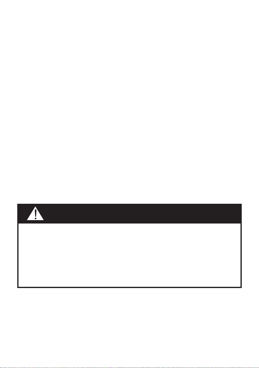
BELAIS36SS600-B
BELAIS42SS600-B
Installation Instructions
Use and Care Information
Instructions d'installation
Utilisez et d'entretien
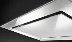
BELLA IS 36" - 42"

2
READ AND SAVE THESE INSTRUCTIONS BEFORE YOU START
INSTALLING THIS RANGEHOOD
WARNING: - TO REDUCE THE RISK OF A RANGE TOP GREASE FIRE:
a) Never leave surface units unattended at high settings. Boilovers cause smoking and
greasy spillovers that may ignite. Heat oils slowly on low or medium setting.
b)AlwaysturnhoodONwhencookingathighheatorwhenambeingfood(i.e.Crepes
Suzette, Cherries Jubilee, Peppercorn Beef Flambé).
c) Clean ventilating fans frequently. Grease should not be allowed to accumulate on fan
orlter.
d) Use proper pan size. Always use cookware appropriate for the size of the surface element.
WARNING: - TO REDUCE THE RISK OF INJURY TO PERSONS IN THE EVENT OF A
RANGE TOP GREASE FIRE, OBSERVE THE FOLLOWING*:
a)SMOTHERFLAMESwithaclose-ttinglid,cookiesheet,ormetaltray,thenturnofftheburner.
BECAREFULTOPREVENTBURNS.IftheamesdonotgooutimmediatelyEVACUATE
AND CALL THE FIRE DEPARTMENT.
b) NEVER PICK UP A FLAMING PAN - You may be burned.
c) DO NOT USE WATER, including wet dishcloths or towels - a violent steam explosion will
result.
d) Use an extinguisher ONLY if:
1. You know you have a Class ABC extinguisher, and you already know how to operate it.
2. Thereissmallandcontainedintheareawhereitstarted.
3. Theredepartmentisbeingcalled.
4. Youcanghttherewithyourbacktoanexit.
* Based on "Kitchen Firesafety Tips" published by NFPA
WARNING - TO REDUCE THE RISK OF FIRE OR ELECTRIC SHOCK, do not use this
fan with any solid-state speed control device.
WARNING - TO REDUCE THE RISK OF FIRE, ELECTRICAL SHOCK, OR INJURY TO
PERSONS, OBSERVE THE FOLLOWING:
1. Use this unit only in the manner intended by the manufacturer. If you have any
questions, contact the manufacturer.
2. Before servicing or cleaning unit, switch power off at service panel and lock the
service disconnecting means to prevent power from being switched on acciden-
tally. When the service disconnecting means cannot be locked, securely fasten a
prominent warning device, such as a tag, to the service panel.
CAUTION: For General Ventilating Use Only. Do Not Use To Exhaust Hazardous or
Explosive Materials and Vapors.
WARNING - TO REDUCE THE RISK OF FIRE, ELECTRICAL SHOCK, OR INJURY TO
PERSONS, OBSERVE THE FOLLOWING:
1. InstallationWorkAndElectricalWiringMustBeDoneByQualiedPerson(s)InAccor-
dance With All Applicable Codes And Standards, Including Fire-Rated Construction.
2. Sufcientairisneededforpropercombustionandexhaustingofgasesthrough
theue(chimney)offuelburningequipmenttopreventbackdrafting.Followthe
heating equipment manufacturer's guideline and safety standards such as those
publishedbytheNationalFireProtectionAssociation(NFPA),andtheAmerican
SocietyforHeating,RefrigerationandAirConditioningEngineers(ASHRAE),and
the local code authorities.

3
3. When cutting or drilling into wall or ceiling, do not damage electrical wiring and
other hidden utilities.
4. Ducted fans must always be vented to the outdoors.
ALL WALL AND FLOOR OPENINGS WHERE THE RANGEHOOD IS INSTALLED MUST
BE SEALED.
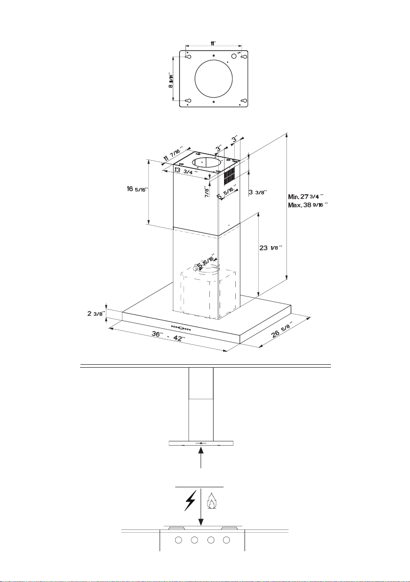
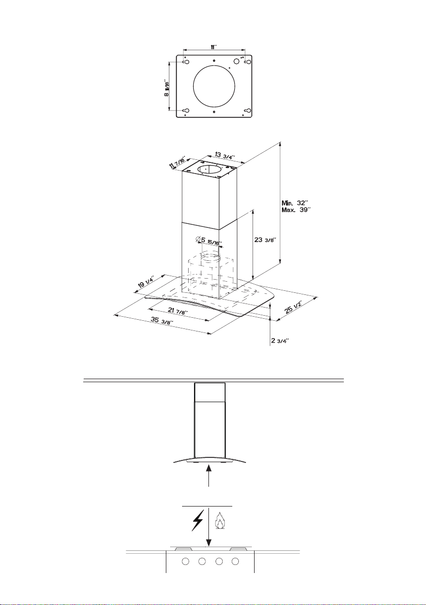
This rangehood requires at least 24" of clearance between the bottom of the rangehood
and the cooking surface or countertop. This hood has been approved by UL at this distance
from the cooktop. Overhead cabinets on both sides of this unit must be a minimum of 18" above
the cooking surface or countertop.
Consult the cooktop or range installation instructions given by the manufacturer before making
any cutouts. MOBILE HOME INSTALLATION The installation of this rangehood must conform
to the Manufactured Home Construction and Safety Standards, Title 24 CFR, Part 3280 (formerly
Federal Standard for Mobile Home Construction and Safety, Title 24, HUD, Part 280).
• Venting system MUST terminate outside the home.
• DO NOT terminate the ductwork in an attic or other enclosed space.
• DO NOT use 4" laundry-type wall caps.
• Flexible-type ductwork is not recommended.
• DO NOT obstruct the ow of combustion and ventilation air.
• Failure to follow venting requirements may result in a re.
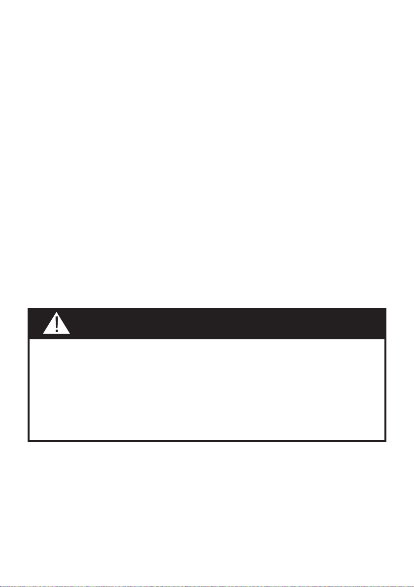
WARNING
!
Cold Weather installations
An additional back draft damper should be installed to minimize backward cold air ow and a
nonmetallic thermal break should be installed to minimize conduction of outside temperatures as
part of the vent system. The damper should be on the cold air side of the thermal break. The break
should be as close as possible to where the vent system enters the heated portion of the house.
VENTING REQUIREMENTS
Determine which venting method is best for your application. Ductwork can extend either through the
wall or the roof.
The length of the ductwork and the number of elbows should be kept to a minimum to provide efcient
performance. The size of the ductwork should be uniform. Do not install two elbows together. Use
duct tape to seal all joints in the ductwork system. Use caulking to seal exterior wall or oor opening
around the cap.
Flexible ductwork is not recommended. Flexible ductwork creates back pressure and air turbulence
that greatly reduces performance.
Make sure there is proper clearance within the wall or oor for exhaust duct before making cutouts.
Do not cut a joist or stud unless absolutely necessary. If a joist or stud must be cut, then a supporting
frame must be constructed.
WARNING - To Reduce The Risk Of Fire, Use Only Metal Ductwork.
CAUTION-Toreduceriskofreandtoproperlyexhaustair,besuretoductairoutside–Do
not vent exhaust air into spaces within walls or ceilings or into attics, crawl spaces, or garages.
4
ELECTRICAL REQUIREMENTS
A 120 volt, 60 Hz AC-only electrical supply is required on a separate 15 amp fused circuit. A time-delay
fuse or circuit breaker is recommended. The fuse must be sized per local codes in accordance with
the electrical rating of this unit as specied on the serial/rating plate located inside the unit near the eld
wiring compartment.
ELECTRICAL INSTALLATION WITH WIRING BOX
THIS UNIT MUST BE CONNECTED WITH COPPER WIRE ONLY. Wire sizes must conform to the
requirements of the National Electrical Code, ANSI/NFPA 70 - latest edition, and all local codes and
ordinances. Wire size and connections must conform with the rating of the appliance. Copies of the
standard listed above may be obtained from:
National Fire Protection Association
Batterymarch Park
Quincy, Massachusetts 02269
This appliance should be connected directly to the fused disconnect (or circuit breaker) through
exible, armored or nonmetallic sheathed copper cable. Allow some slack in the cable so the
appliance can be moved if servicing is ever necessary. A UL Listed, 1/2" conduit connector must
be provided at each end of the power supply cable (at the appliance and at the junction box).
When making the electrical connection, cut a 1 1/4" hole in the wall. A hole cut through wood
must be sanded until smooth. A hole through metal must have a grommet.
• Electrical ground is required on this rangehood.
• If cold water pipe is interrupted by plastic, nonmetallic gaskets or other materials, DO
NOT use for grounding.
• DO NOT ground to a gas pipe.
• DO NOT have a fuse in the neutral or grounding circuit. A fuse in the neutral or
grounding circuit could result in electrical shock.
• Check with a qualied electrician if you are in doubt as to whether the rangehood is
properly grounded.
• Failure to follow electrical requirements may result in a re.
WARNING
!
5
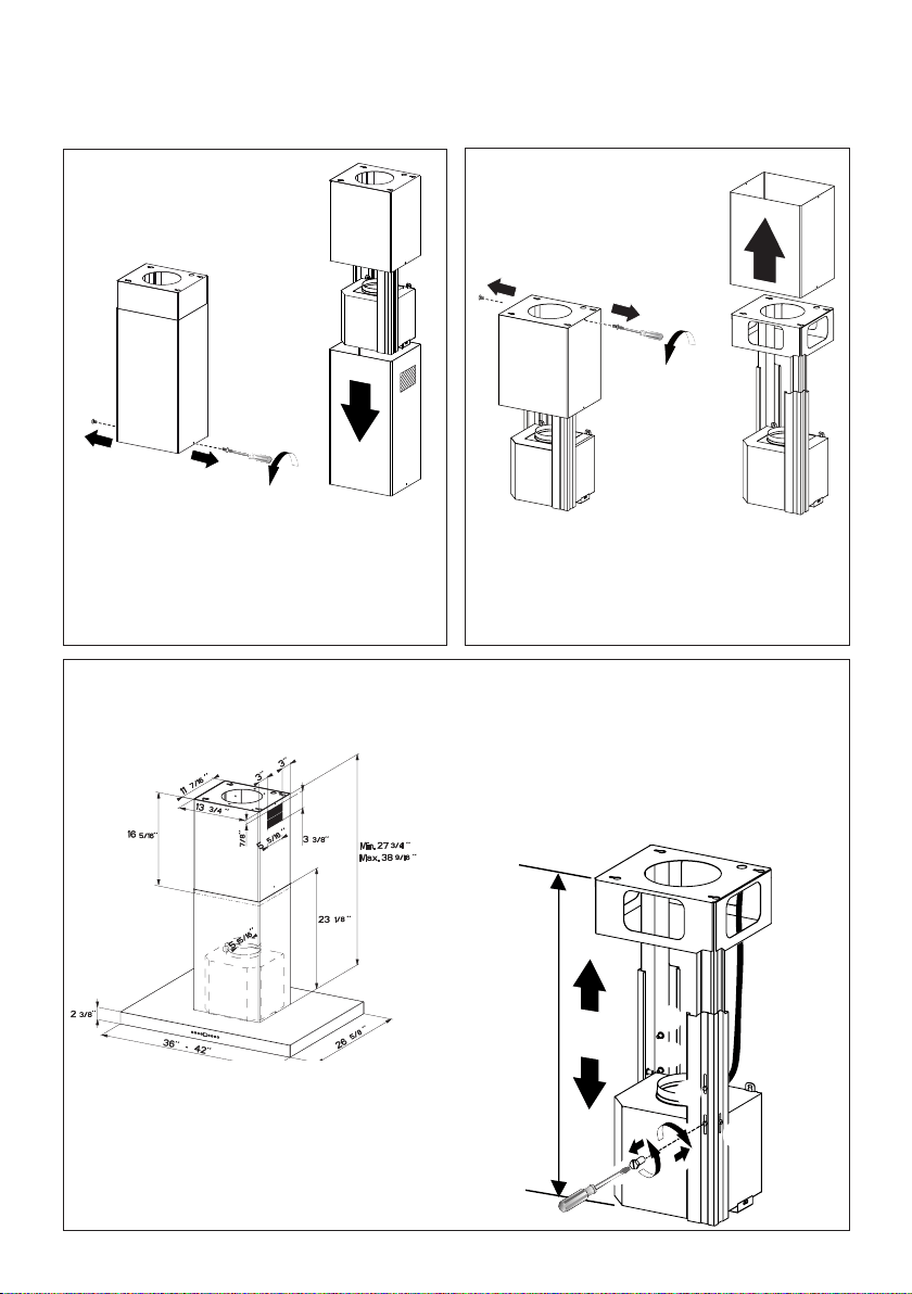
RANGEHOOD DIMENSIONS
Min. 24"
6
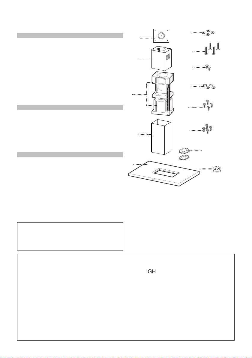
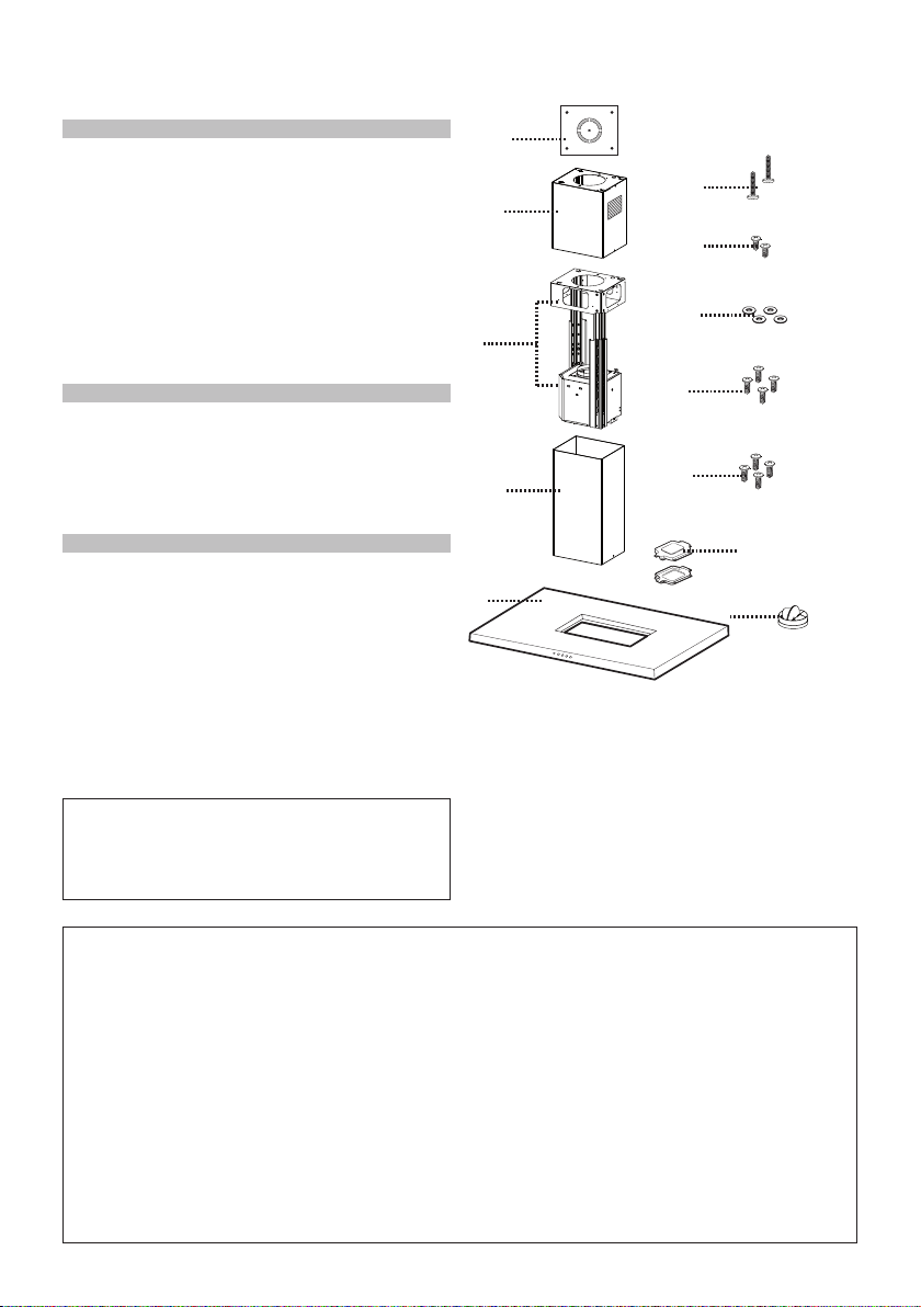
MAIN PARTS
Components
Ref. Qty. Product Components
1 1 Hood Body, complete with: Con-
trols, Light, Filters, Blower.
2 1 Telescopic Chimney comprising:
2.1 1 Upper Section
2.2 1 Lower Section
7.1 1 Telescopic frame complete with
extractor, consisting of:
7.1a 1 Upper frame
7.1b 1 Lower frame
10 1 Damper ø 5 7/8"
24 1 Junction Box
Ref. Qty. Installation Components
12f 4 Screws 1/4" x 3 1/8"
12c 2 Screws 1/8" x 1/4"
12e 4 Screws 1/8" x 3/8"
12q 4 Screws 1/4" x 9/16"
21 1 Drilling template
22 4 1/4" int. dia washers
23 4 1/4" Nuts
Qty. Documentation
1 Instruction Manual
Available Accessories
-HighCeilingKitthatreplacesthelowerue.-sku#HIGHBELAIS.
-DuctlessKit-IncludesDuctlessDiverter,CharcoalFilters,Lowerchimneywithvent
grates-sku#DUCT2
-6"Make-UpAirDamperKit-MUDAMPER6
-8"Make-UpAirDamperKit-MUDAMPER8
-CFMReducerKit-CFMRED
-ActivatedCharcoalFilterAccessory-sku#FILTER2
- Wireless RemoteControlAccessory-REMCTRL
Parts needed
-6"RoundMetalductwork
10
1
2.2
2.1
21
7.1
12q
22
12c
12e
12f
24
7.1a
7.1b
23
7
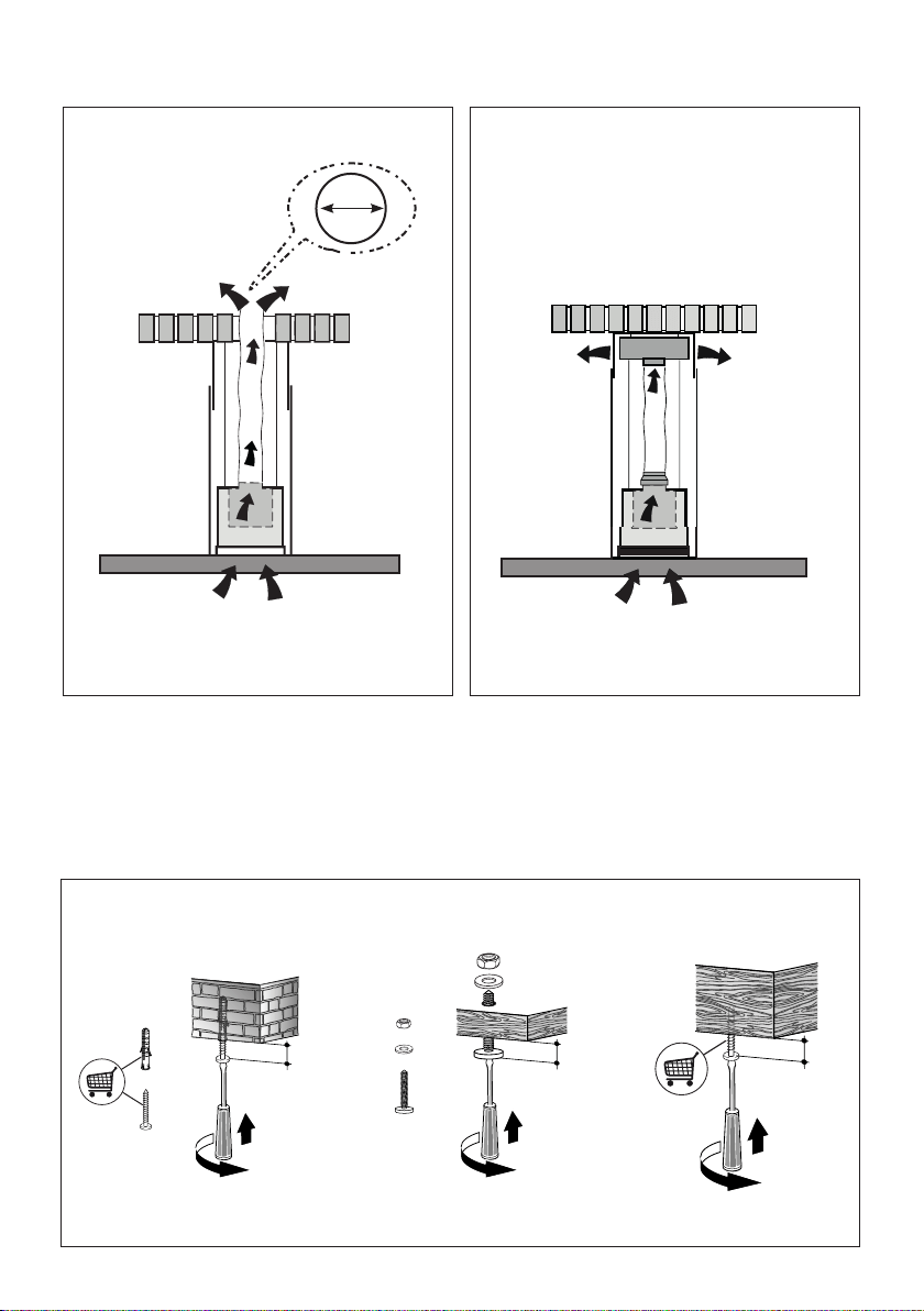
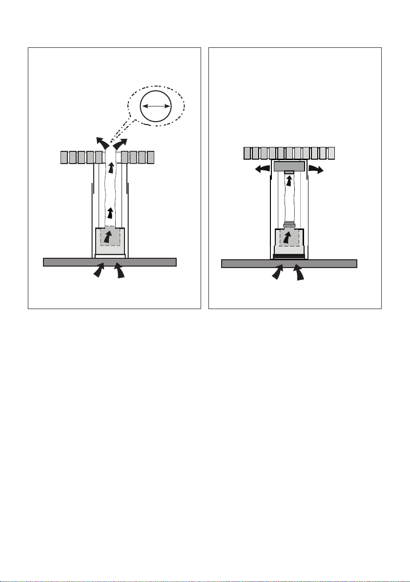
Choose your ducting method
Non Ducted - Recirculation OptionDucted Venting Options Installation
RequiresDuctlessAccessoryKit
(purchasedseparately)
6 "
K
OK!
3/16 ”
T
OK!
3/16 ”
OK!
3/16 ”
Components for installation to the ceiling
Thesefastenersmayneedtobepurchasedseparatelydependingonyourinstallation.

8
1
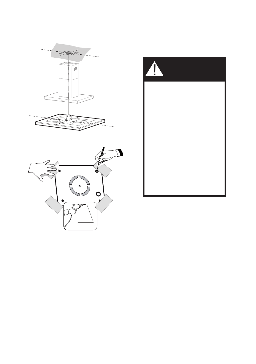
Putathick,protectivecoveringovercooktop,
set-in range or countertop to protect from
damageordirt.
Determineandclearlymarkwithapencilonthe
ceilingwheretherangehoodwillbeinstalled.
A template 21 for mounting the support is
supplied in the carton with the support. Use
thistemplatetomarkholesfor
supportontheceiling.
Determine and make necessary cuts for the
ductwork.Theduct openingisshownonthe
mountingtemplate.Install
ductworkbeforemountingthehood.
Determine the proper location for the Power
Supply Cable as indicated on the template.
Use a 1 1/4" Drill Bit to make this hole. Run
thePowerSupplyCable.Usecaulkingtoseal
aroundthehole.
A knockout for threading through the Power
Supply from the ceiling is located on the top
oftheframe.DonotconnectthePowerCable
totheWiringBoxorpowerupthehoodatthis
time.Runenoughpowercablefromtheceiling
toreachthewiringboxonthehood.
Ø 10 mm
x4
21
6
4
21
6
´
´
1 1/4"
Donotmakeanycutoutsuntilyouhavedecidedwhetherthisinstallationwillbeductedor
non-ductandthenplanaccordingly.
DUE TO THE SIZE AND
WEIGHT OF THIS RANGE-
HOOD, THE SUPPORT MUST
BE FIRMLY ATTACHED TO
THE CEILING. For plaster or
sheet rock ceiling, the support
must be attached to the joists.
If this is not possible, a support
structure must be built behind
the plaster or sheet rock. The
manufacturer assumes no re-
sponsibility forinjury or damage
caused by improper installa-
tions.
WARNING
!
9
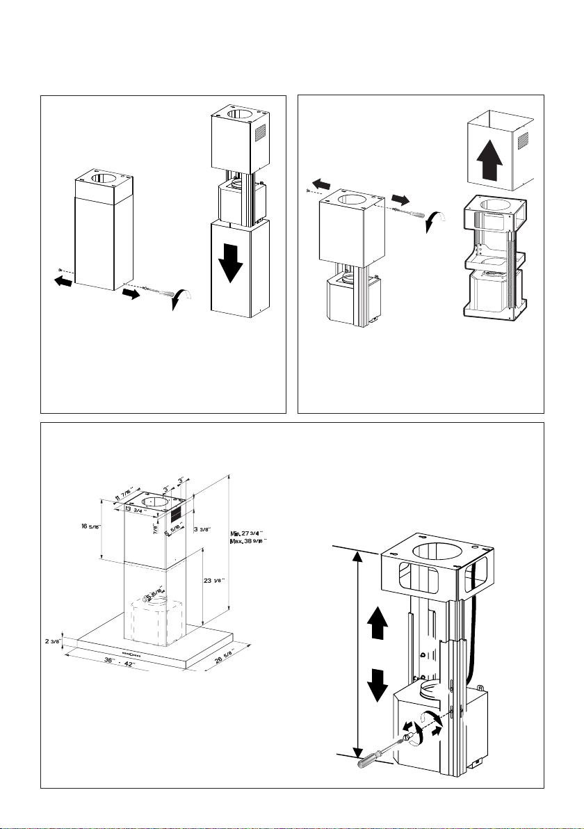
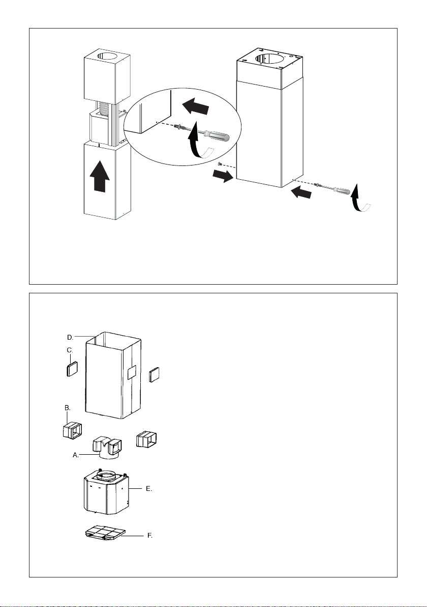
Chimney Flues Must Be Removed Before Installing the Hood
2
3
4
Loosen the two screws fastening the lower chimney
and remove this from the lower frame.
If you need to adjust the height of the frame,
proceed as follows:
• Unfasten the metric screws joining the two
columns, located at the sides of the frame
(1,2,3,4,5,6).
• Adjust the frame to the height required, then
ret all the screws removed as above.
Loosen the two screws fastening the upper chimney
and remove this from the upper frame.
10
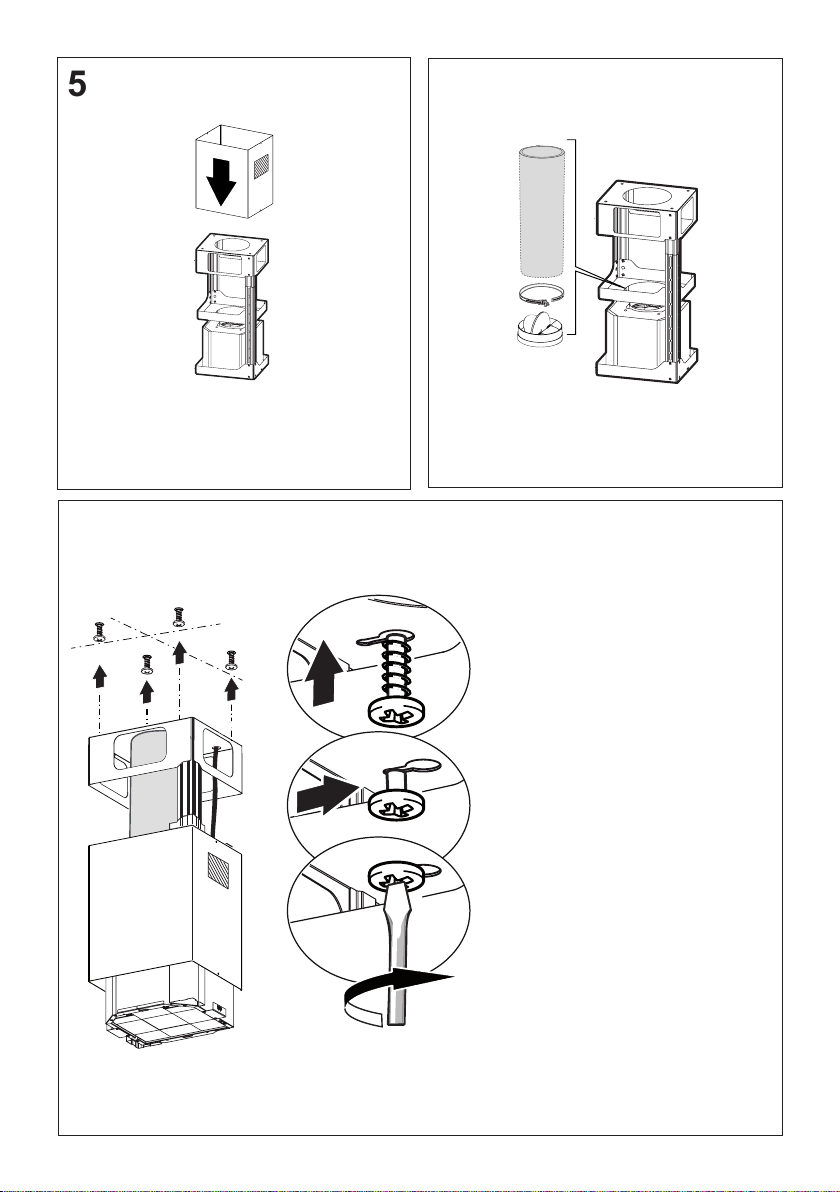
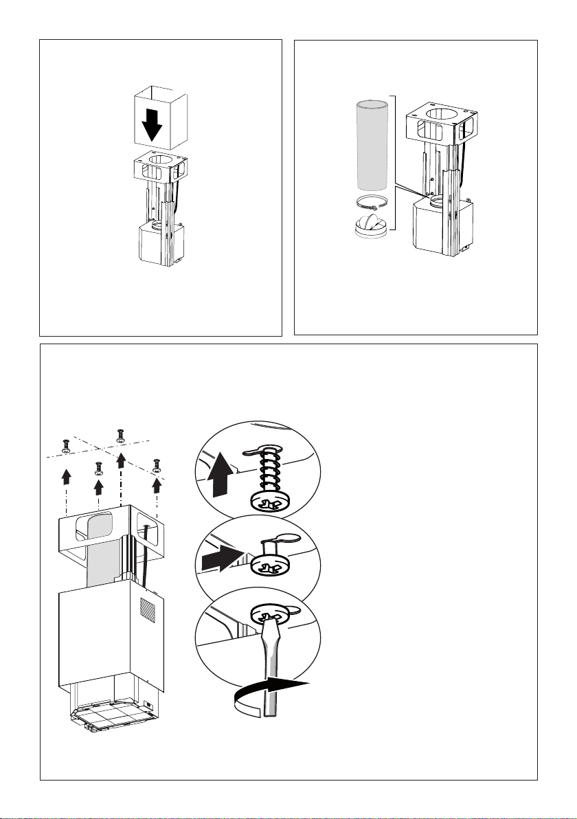
5
After the regulation for height adjustment, insert
the upper chimney stack from above, and leave it
running free on the frame.
Upper Flue Must Be In Place
Before Proceeding
6
Install Damper that is included with the Hood before
connecting to the ductwork.
Only for Ducted Venting
Installation
7
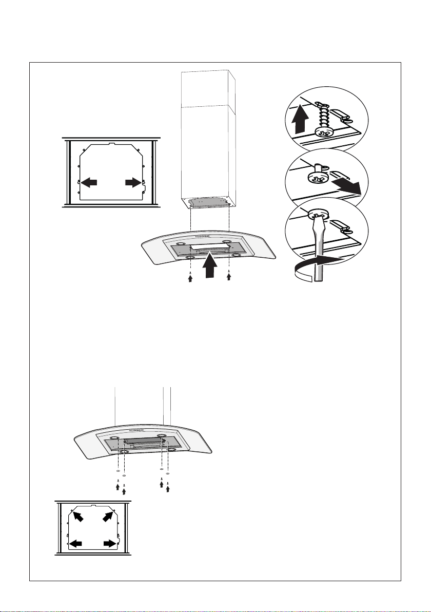
Now take either your woods screws or bolts
depending on your set-up and screw all four
into the pilot holes and leave 1/4" of the
heads exposed.
Next install a UL or CSA listed strain relief
in the wiring box so that the screws can
be tightened after the chimney support is
attached to the ceiling.
Now lift the chimney support into it's nal
position and feed the electrical supply through
the strain relief.
Next position the chimney support so that
the large end of the keyhole slots are over
the ceiling attachment screws or bolts. Then
push the chimney support so that the bolts
are in the neck of the slots. Tighten all four
screws or bolts securely.
• The frame mountings must be secure to
withstand the weight of the hood and any
stresses caused by the occasional side
thrust applied to the device. On completion,
check that the base is stable, even if the
frame is subjected to bending.
• In all cases where the ceiling is not
strong enough at the suspension point,
the installer must provide strengthening
using suitable plates and backing pieces
anchored to the structurally sound parts.
11
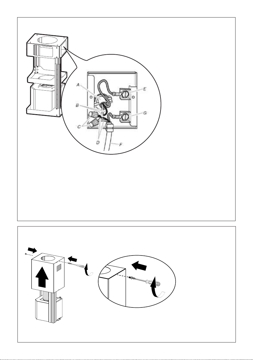
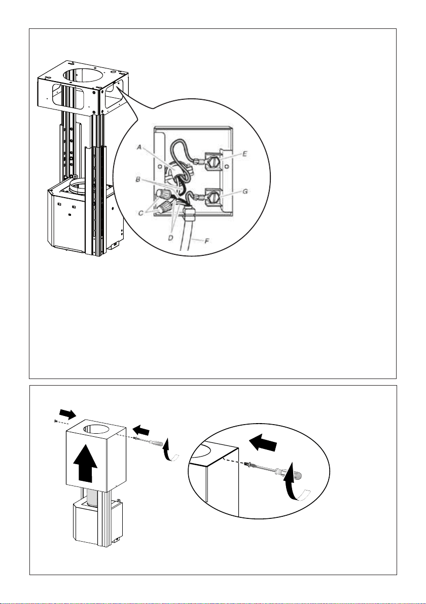
Installation of wiring
connection
Remove the cover from the
eld wiring compartment.
DO NOT turn on the power until
installation is complete!
Connect the Power Supply
Cable to the rangehood.
Connect the Green (Green and
Yellow) ground wire under the
Green grounding screw. Attach
the White lead of the power
supply to the White lead of the
rangehood with a twist-on type
wire connector.
Attach the Black lead of the
power supply to the Black lead
of the rangehood with a twist-
on type wire connector.
Replace the eld wiring compart-
ment cover and the grease lters.
A. Home power supply cable
B. Black wires
C. UL listed wire connectors
D. White wires
E. Green (or bare) ground wire from home power supply connected to green ground screw
F. Range hood power supply cable
G. Range hood power supply cable connected to green ground screw
Remove the cover from the eld wiring compartment.
Connect the Power Supply Cable to the rangehood.
Connect the Green (Green and Yellow) ground wire under the
wire connector. Attach the Black lead of the power supply
to the Black lead of the rangehood with a twist-on type wire
The UPPER CHIMNEY
COVER
, use the UPPER
CHIMNEY COVER supplied
attach the UPPER CHIMNEY
COVER.
Make sure to seal all joints with
The LOWER CHIMNEY
COVER
Install the LOWER CHIMNEY
COVER by sliding it up over
the support and the UPPER
CHIMNEY COVER.
For ductless installations, line up the DUCTLESS DIVERTER
EXTENSIONS HORIZONTAL
in the LOWER CHIMNEY COVER
B. Black wires
C. UL listed wire connectors
CHIMNEY COVER
, place the DUCTLESS
exhaust opening of the EASY
CUBE . Fit the DUCTLESS
DIVERTER EXTENSIONS
HORIZONTAL
9
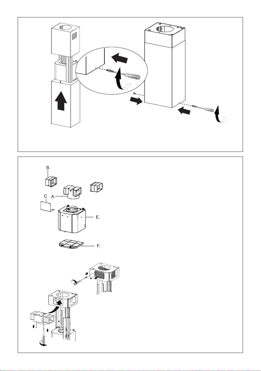
Position the upper chimney section and x the upper
part to the frame using the 2 screws removed previously.
8
12
11
Similarly, position the lower chimney section and x the lower part to the frame using the 2 screws
removed previously.
10
Only For Ductless Installations
Ductless installations require a Ductless
Conversion Kit whose components
are pictured in FIGURE. Do not use the
DAMPER for ductless installations.
Insert the Connector extensions B into the
side of the Connector A.
Insert the Connector A into the Support
bracket C and x it with the screws.
Fasten the Support bracket C, xing it to the
upper part with the Screws.
Make sure that the Connector extensions
outlet B is in correspondence with the
Chimney openings both horizontally and
vertically.
Remove the cover from the eld wiring compartment.
Connect the Power Supply Cable to the rangehood.
Connect the Green (Green and Yellow) ground wire under the
wire connector. Attach the Black lead of the power supply
to the Black lead of the rangehood with a twist-on type wire
The UPPER CHIMNEY
COVER
, use the UPPER
CHIMNEY COVER supplied
attach the UPPER CHIMNEY
COVER.
Make sure to seal all joints with
The LOWER CHIMNEY
COVER
Install the LOWER CHIMNEY
COVER by sliding it up over
the support and the UPPER
CHIMNEY COVER.
For ductless installations, line up the DUCTLESS DIVERTER
EXTENSIONS HORIZONTAL
in the LOWER CHIMNEY COVER
B. Black wires
C. UL listed wire connectors
CHIMNEY COVER
, place the DUCTLESS
exhaust opening of the EASY
CUBE . Fit the DUCTLESS
DIVERTER EXTENSIONS
HORIZONTAL
FIGURE 12
Remove the cover from the eld wiring compartment.
Connect the Power Supply Cable to the rangehood.
Connect the Green (Green and Yellow) ground wire under the
wire connector. Attach the Black lead of the power supply
to the Black lead of the rangehood with a twist-on type wire
The UPPER CHIMNEY
COVER
, use the UPPER
CHIMNEY COVER supplied
attach the UPPER CHIMNEY
COVER.
Make sure to seal all joints with
The LOWER CHIMNEY
COVER
Install the LOWER CHIMNEY
COVER by sliding it up over
the support and the UPPER
CHIMNEY COVER.
For ductless installations, line up the DUCTLESS DIVERTER
EXTENSIONS HORIZONTAL
in the LOWER CHIMNEY COVER
B. Black wires
C. UL listed wire connectors
CHIMNEY COVER
, place the DUCTLESS
exhaust opening of the EASY
CUBE . Fit the DUCTLESS
DIVERTER EXTENSIONS
HORIZONTAL
13
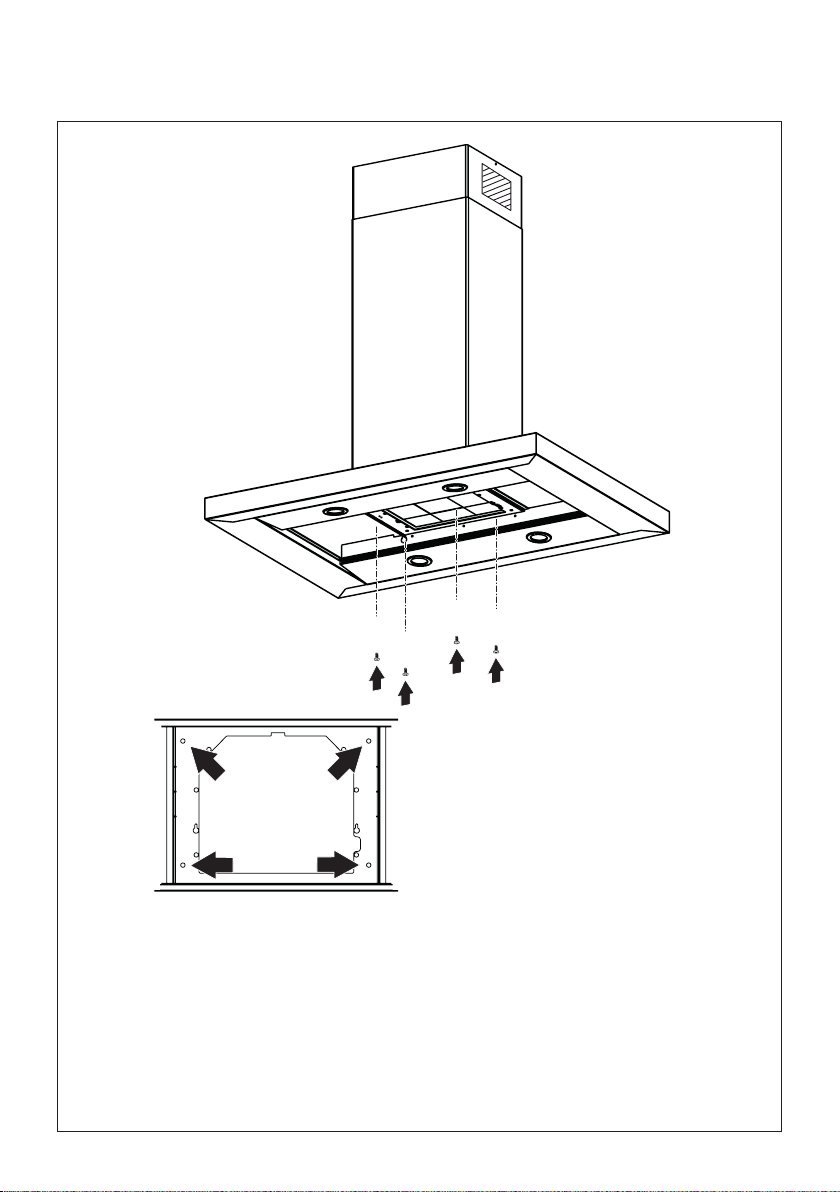
12
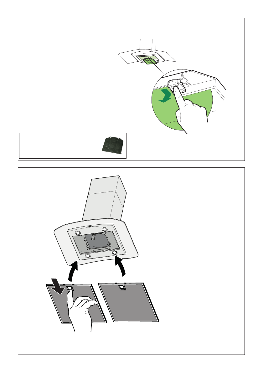
Remove the grease lters from the hood canopy.
Remove any activated charcoal lters.
Working from below, x the hood canopy to the frame where indicated, using the 4 screws 12f, then
tighten all the screws securely.
Attachment of Hood Canopy
I
[
14
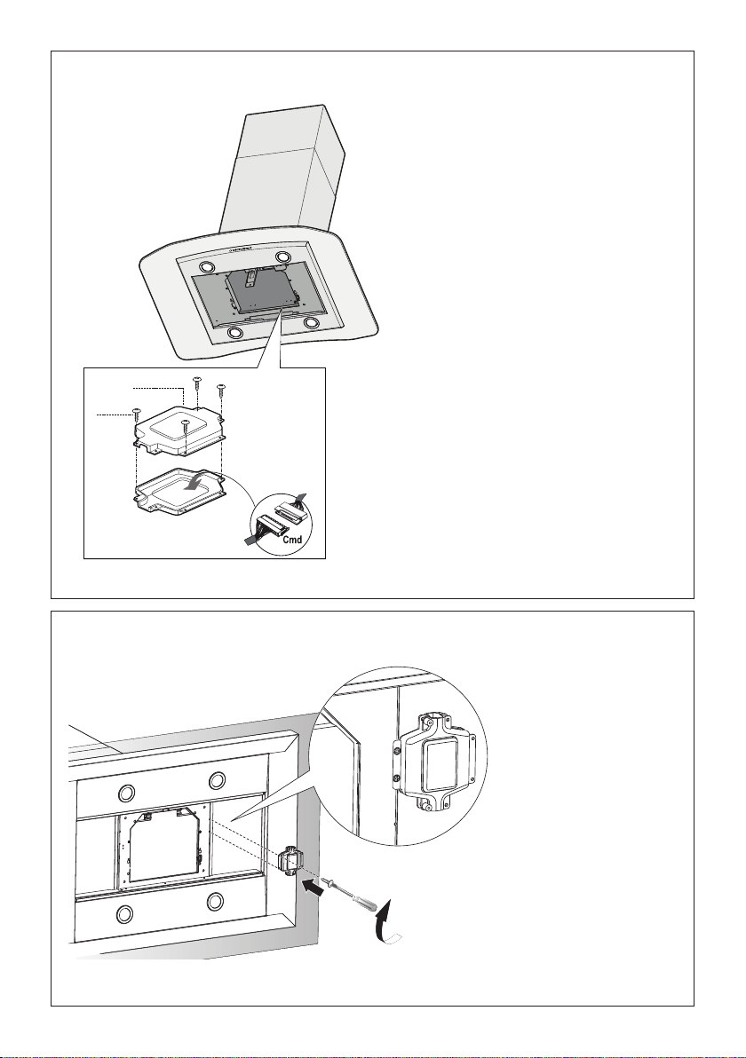
13
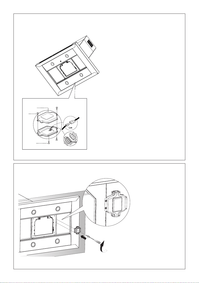
ConnectthecontrolconnectorCmdand.
ConnectthelightsconnectorLux.
Placetheconnectorsinthejunctionbox24and
closeitusingthe4screwsprovided.
14
12c x 2
Fixthejunctionbox
tothehoodbody
usingthe2screws
12cprovided.
H
Make the Internal Electrical Connection
24
12e
12c
15
14
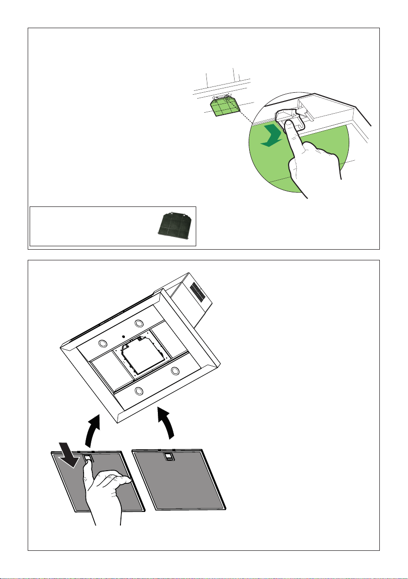
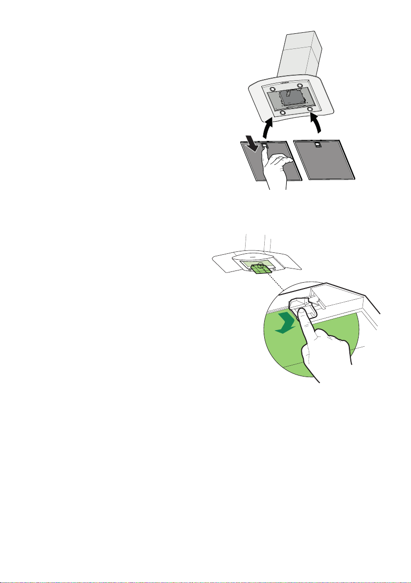
For Non-Ducted Recirculation
Option
RequiredActivatedCharcoalFilter
Accessory-sku#-FILTER2
(purchasedseparately)
Attacha
charcoal
lterinthe
correct
positionand
blockitby
thexing
hooksas
shown.
Unlockthexinghooks(towardsthebackofthe
inserthood)toremove.
Reinstall the grease lters
from the hood canopy.
15
16
USE AND CARE INFORMATION
For Best Results
Starttherangehoodseveralminutesbeforecookingtodevelopproperairow.Allowtherangehoodto
operateforseveralminutesaftercookingiscompletetoclearallsmokeandodorsfromthekitchen.
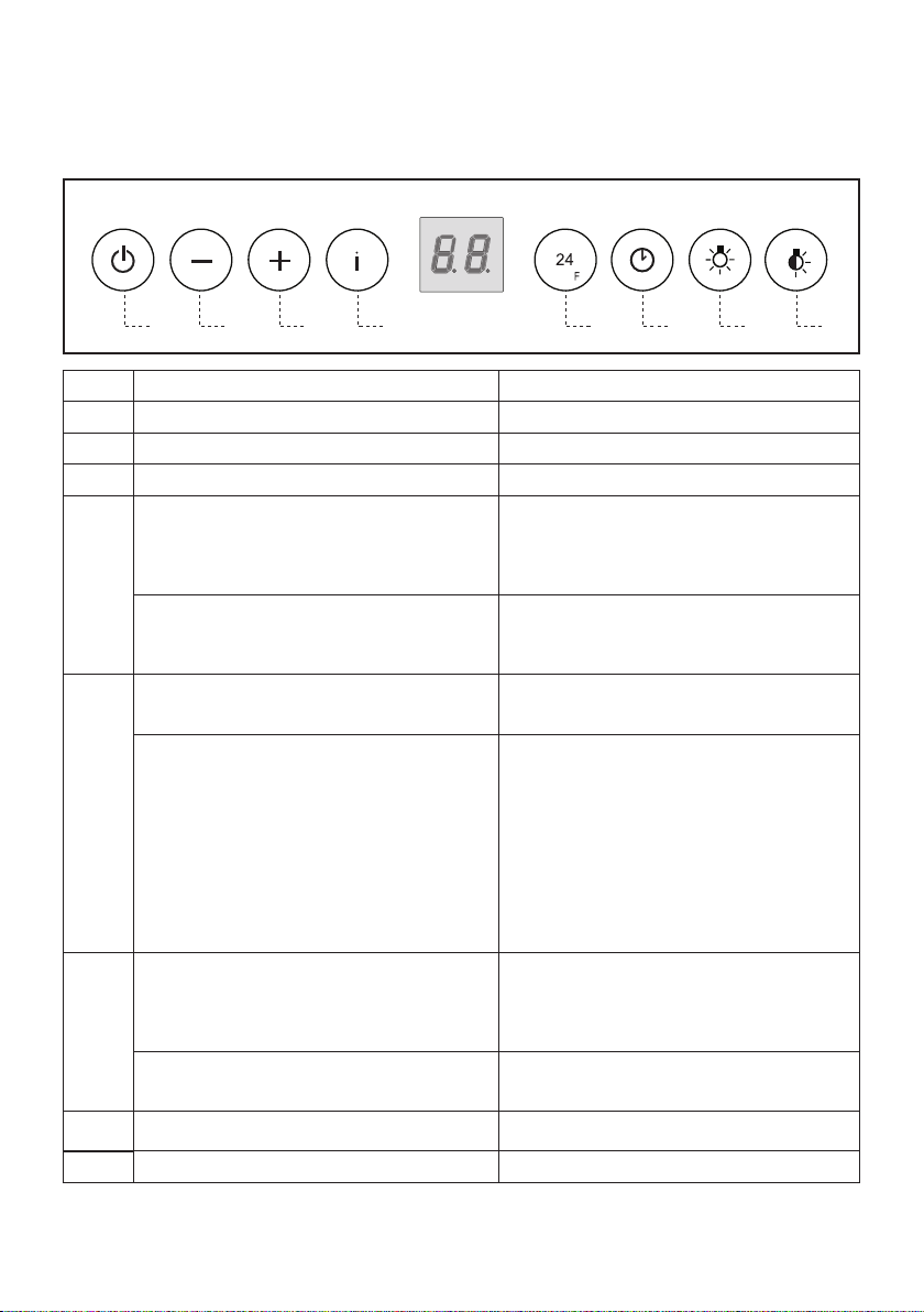
Button Function Display
A Turnsthesuctionmotoronandoffatspeedone. Displaysthesetspeed
B Decreasestheworkingspeed. Displaysthesetspeed
C Increasestheworkingspeed. Displaysthesetspeed
D Activateintensivespeedfromanyotherspeed,
includingmotoroff.Thisspeedissettooperatefor
6minutes,afterwhichthesystemreturnstothe
speedthatwassetbefore.Suitabletodealwith
maximumlevelsofcookingfumes.
DisplaysHIandthetimeremainingoncevery
second.
Pressandholdthebuttonforapproximately5
seconds,withalltheloadsturnedoff(Motorand
Lights),toturntheActivatedCharcoalFilteralarm
OnandOff.
FC+Punto(2ashes)–AlarmOn.
FC+Punto(1ash)–AlarmOff.
E
24Hfunction
Turnsthesuctionmotoronatspeedoneandeffects
one10minuteextractioneveryhour.
Displays24andthespotatthebottomrightashes
onceeverysecond,whilethemotorisrunning.
Itisdisabledbypressingthebutton.
Whentheltersalarmistriggered,thealarmcan
beresetbypressingandholdingthisbuttonfor
approximately3seconds.
Theseindicationsareonlyvisiblewhenthemotor
isturnedoff.
FFashesthreetimes.
Whentheprocedureterminates,theindication
shownpreviouslyturnsoff:
FG indicatestheneedtowashthemetal
greaselters.ThealarmistriggeredaftertheHood
hasbeeninoperationfor100workinghours.
FC indicatestheneedtochangethe
activatedcharcoallters,andalsotowashthe
metalgreaselters.Thealarmistriggeredafterthe
Hoodhasbeeninoperationfor200workinghours.
F Delayfunction
Activateautomaticswitch-offwitha30’delay.
Suitabletocompleteeliminationofresidualodours.
Canbeactivatedfromanyposition,andisdisabled
bypressingthebuttonorturningthemotoroff.
Displaystheoperatingspeedandthespotatthe
bottomrightashesonceasecond.
Pressandholdthebuttonforapproximately5
seconds,withalltheloadsturnedoff(Motorand
Lights),toturntheRemoteControlOnandOff.
IR+Punto(2ashes)–RemoteControlOn.
IR+Punto(1ash)–RemoteControlOff.
G
Turnsthelightingsystemonandoffatmaximum
intensity.
H
TurnstheCourtesyLightingonandoff.
17
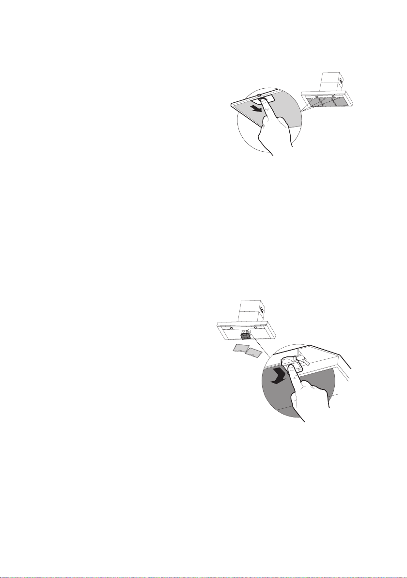
Cleaningmetalgreaselters
They can be washed in the dishwasher, and need to be cleaned
whenever the FG sign appears on the display or at least once
every 2 months use, or more frequently if use is particularly
intensive.
Resetting the alarm signal
• Turn the Lights and the Suction motor off, then disable the
24h function, if enabled.
• Press button E (see the paragraph on Use).
Cleaning the Filters
• Remove the Filters one at a time, pushing them towards
the back of the unit and at the same time pulling downward.
• Wash the Filters without bending them, and leave them to
dry completely before replacing. (If the surface of the lter
changes colour as time goes by, this will have absolutely no
effect on the efciency of the lter itself.)
• Replace, taking care to ensure that the handle faces forwards.
Replacing Activated Charcoal Filter
It cannot be washed or regenerated, and must be changed when
the FC symbol on the display appears, or at least once every 4
months. The Alarm signal, if it has been activated, only appears
when the Suction motor is turned on.
Resetting the alarm signal
• Turn the Lights and the Suction motor off, then disable the
24h function, if enabled.
• Press button E (see the paragraph on Use).
Cleaning the Filters
• Remove the Filters one at a time, pushing them towards
the back of the unit and at the same time pulling downward.
• Remove the saturated charcoal lter by releasing the xing
hooks.
• Fit the new lter and fasten it in its correct position.
• Replace, taking care to ensure that the handle faces forwards.
Lighting unit
• LED lights must be replaced by Faber factory authorized
service.

18
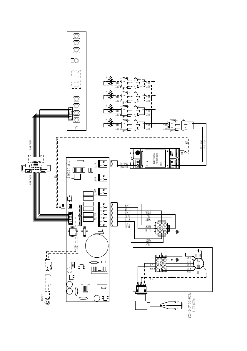
Wiring Diagram

19
January 4, 2016
FABER CONSUMER WARRANTY & SERVICE
All Faber products are warranted against any defect in materials or workmanship for the original purchaser
for a period of 1 year from the date of original purchase (requires proof of purchase). This warranty covers
labor and replacement parts. Faber, at its option, may repair or replace the product or components
necessary to restore the product to good working condition. To obtain warranty service, contact the dealer
from whom you purchased the range hood, or the local Faber distributor. If you cannot identify a local Faber
distributor, contact us at (508) 358-5353 for the name of a distributor in your area.
The following is not covered by Faber's warranty:
1. Service calls to correct the installation of your range hood, to instruct you how to use your range hood, to
replace or repair house fuses or to correct house wiring or plumbing.
2. Service calls to repair or replace range hood light bulbs, fuses or filters. Those consumable parts are
excluded from warranty coverage.
3. Repairs when your range hood is used for other than normal, single-family household use.
4. Damage resulting from accident, alteration, misuse, abuse, fire, flood, acts of God, improper installation,
installation not in accordance with electrical or plumbing codes or Faber documentation, or use of products
not approved by Faber.
5. Replacement parts or repair labor costs for units operated outside the United States or Canada, including
any non-UL or C-UL approved Faber range hoods.
6. Repairs to the hood resulting from unauthorized modifications made to the range hood.
7. Expenses for travel and transportation for product service in remote locations and pickup and delivery
charges. Faber range hoods should be serviced in the home.
THIS WARRANTY DOES NOT ALLOW RECOVERY OF INCIDENTAL OR CONSEQUENTIAL DAMAGES, INCLUDING, WITHOUT
LIMITATION, DIRECT, INDIRECT, INCIDENTAL, SPECIAL OR CONSEQUENTIAL DAMAGES, PERSONAL INJURY/WRONGFUL
DEATH OR LOST PROFITS FABER WARRANTY IS LIMITED TO THE ABOVE CONDITIONS AND TO THE WARRANTY PERIOD
SPECIFIED HEREIN AND IS EXCLUSIVE. EXCEPT AS EXPRESSLY SPECIFIED IN THIS AGREEMENT, FABER DISCLAIMS ALL
EXPRESS OR IMPLIED CONDITIONS, REPRESENTATIONS, AND WARRANTIES INCLUDING, WITHOUT LIMITATION, ANY
IMPLIED WARRANTIES OF MERCHANTABILITY OR FITNESS FOR A PARTICULAR PURPOSE
.
This warranty gives you specific legal rights that may vary from state to state.
Model#: ______________________________ Serial #: _____________________________

20
VEUILLEZ LIRE ET CONSERVER LA PRÉSENTE NOTICE AVANT DE
COMMENCER L'INSTALLATION DE LA HOTTE DE CUISINE
AVERTISSEMENT : POUR RÉDUIRE LE RISQUE D'UN FEU DE GRAISSE SUR LA TABLE DE
CUISSON:
a) Ne laissez jamais sans surveillance les éléments de la surface de cuisson à température élevée.
Les bouillonnements excessifs peuvent provoquer de la fumée et les débordements de graisse
peuvents'enammer.L'huiledoitêtrechaufféelentement,àunetempératurebasseoumoyenne.
b) Assurez-vous de toujours mettre en marche le ventilateur de la hotte lorsque vous cuisinez à
températureélevéeoupréparezunmetsambé(p.ex.crêpesSuzette,cerisesjubilé,bœufambé).
c) Nettoyez régulièrement les ventilateurs d'aspiration. Assurez-vous de ne pas laisser de la
graisses'accumulersurleventilateurouleltre.
d)Utiliseztoujoursdespoêlesetcasserolesdelatailleappropriée.Utiliseztoujoursdesustensiles
de cuisine de la taille adaptée à celle de l'élément chauffant.
AVERTISSEMENT:-POURPRÉVENIRLESBLESSURESENCASDEFEUDEGRAISSESURLA
TABLEDECUISSON,SUIVEZLESRECOMMANDATIONSSUIVANTES*:
a) ÉTOUFFEZ LES FLAMMES à l'aide d'un couvercle hermétique, d'une plaque à biscuits ou d'un
plateau métallique, puis éteignez le brûleur. FAITES ATTENTION AUX BRÛLURES. Si le feu ne
s'éteint pas immédiatement, QUITTEZ LES LIEUX ET APPELEZ LES POMPIERS.
b) NE PRENEZ JAMAIS UNE CASSEROLE EN FLAMME - Vous pourriez vous brûler.
c) N'UTILISEZ JAMAIS DE L'EAU, ni un linge à vaisselle ou un torchon mouillé, pour éteindre le
feu. Cela pourrait provoquer une violente explosion de vapeur.
d)UtilisezunextincteurUNIQUEMENTsi:
1. Vousêtescertainqu'ils'agitd'unextincteurdeclasseABCetquevousconnaissezbien
son mode d'emploi.
2. Le feu est de faible intensité et se limite à l'endroit où il a démarré.
3. Les pompiers ont déjà été appelés.
4. Unevoiedesortiesetrouvederrièrevouspendantquevouséteignezlesammes.
* D'après le guide «Kitchen Firesafety Tips» publié par la NFPA aux États-Unis
AVERTISSEMENT - POUR RÉDUIRE LE RISQUE D'INCENDIE OU DE CHOC ÉLECTRIQUE, n'utilisez
jamais ce ventilateur en association avec un dispositif de réglage de vitesse à semi-conducteurs.
AVERTISSEMENT - POUR RÉDUIRE LES RISQUES D'INCENDIE, DE CHOC ÉLECTRIQUE OU
DEBLESSURECORPORELLE,RESPECTEZLESINSTRUCTIONSSUIVANTES:
1. Utilisez cet appareil uniquement de la façon prévue par le fabricant. Pour toute question,
communiquez avec le fabricant.
2. Avant de procéder à l'entretien ou au nettoyage de l'appareil, coupez l'alimentation au
niveau du panneau électrique et verrouillez-le pour vous assurer que l'électricité n'est pas
rétablie accidentellement. S'il n'est pas possible de verrouiller le dispositif d'interruption de
l'alimentation,afchezdefaçonfermeetbienvisibleunavisdedanger,parexempleàl'aide
d'une étiquette sur le panneau.
ATTENTION:Destinéàunusagedeventilationgénéraleuniquement.N'utilisezpascedispositif
pour l'aspiration de vapeurs ou de matériaux dangereux ou explosifs.
AVERTISSEMENT - POUR RÉDUIRE LES RISQUES D'INCENDIE, DE CHOC ÉLECTRIQUE OU
DEBLESSURECORPORELLE,RESPECTEZLESINSTRUCTIONSSUIVANTES:
1. L'installationetlebranchementélectriquedoiventêtreréalisésparuntechnicienqualié
et conformément à tous les codes et normes en vigueur, incluant ceux concernant la con-
struction à l'épreuve du feu.
2. Andegarantirunecombustionetuneévacuationadéquatesdesgazparlesconduites
de la cheminée des appareils à combustion, une bonne aération est nécessaire pour éviter
le refoulement. Respectez les lignes directrices fournies par le fabricant du matériel chauf-
fant, ainsi que les normes de sécurité comme celles publiées par la National Fire Protection
Association(NFPA)etlaAmericanSocietyforHeating,RefrigerationandAirConditioning
Engineers(ASHRAE)auxÉtats-Unis,ainsiquelescodesenvigueurdansvotrerégion.
21
3. Lorsque vous faites une ouverture ou percez dans un mur ou le plafond, veillez à ne pas
endommagerleslsélectriquesoud'autresdispositifscachés.
4. Lesventilateurscanalisésdoiventtoujoursêtreraccordésàl'extérieur.
T
OUTE OUVERTURE DANS LE MUR OU LE PLANCHER À PROXIMITÉ DE LA HOTTE DOIT
ÊTRE SCELLÉE.
Unespacelibred'aumoins24"estrequis entre le bas de la hotte et la surface de cuisson ou
le comptoir. Cette hotte a été homologuée par l'UL à cette distance de la surface de cuisson. Les
armoires suspendues de chaque côté de l'appareil doivent se trouver à au moins 18" de la surface
de cuisson ou du comptoir.
Consultez la notice d'installation de la surface de cuisson ou de la hotte fournie par le fabricant avant
de pratiquer des ouvertures. INSTALLATION DANS UNE MAISON MOBILE L'installation de cette
hotte doit être conforme à la Partie 3280 de la norme Manufactured Home Construction and Safety
Standards, Title 24 CFR (précédemment la partie 280 de la norme Federal Standard for Mobile Home
Construction and Safety, Title 24, HUD).
Installation dans les climats froids
Le système de ventilation doit prévoir un registre antirefoulement supplémentaire pour réduire le ux
d'air froid inverse, ainsi qu'une barrière thermique pour réduire la conduction des températures ex-
térieures. Le registre doit être installé du côté air froid par rapport à la barrière thermique. La barrière
thermique doit être positionnée le plus près que possible de l'endroit où le système de ventilation
pénètre dans la partie chauffée de la maison.
CRITÈRES DE VENTILATION
Déterminez quelle méthode de ventilation est mieux adaptée à votre application. Les conduits peuvent
passer par le mur ou le toit.
Pour garantir une meilleure efcacité, la longueur des conduits et le nombre de coudes doivent être le
plus limités que possible. Le diamètre des conduits devrait être uniforme. N'installez pas deux coudes
ensemble. Utilisez un ruban pour canalisations an de sceller tous les joints du système de conduits.
Utilisez un calfeutrage pour sceller les ouvertures dans le mur extérieur ou le plancher, autour du clapet.
Il n'est pas recommandé d'utiliser des conduits exibles. Les conduits exibles provoquent une con-
tre-pression et de la turbulence qui diminuent grandement l'efcacité de l'appareil.
Assurez-vous que l'espace libre dans le mur ou le plancher est sufsant pour le conduit d'évacuation
avant de pratiquer les ouvertures. Ne coupez jamais une poutre ou un chevron, sauf si c'est absolu-
ment nécessaire. S'il s'avère nécessaire de couper une poutre ou un chevron, la construction d'un
renforcement est requise.
AVERTISSEMENT - Pour réduire le risque d'incendie, utilisez uniquement des conduits métalliques.
ATTENTION - Pour réduire le risque d'incendie et pour évacuer adéquatement l'air, assu-
rez-vousderaccorderlesconduitsàl'extérieur–Nediffusezpasl'aird'évacuationdans
des espaces à l'intérieur des murs ou du plafond, ou encore à l'intérieur d'un grenier, d'une
galerie technique ou d'un garage.
• Le système de ventilation DOIT déboucher à l'extérieur.
• NE FAITES PAS déboucher les conduits dans un grenier ou un autre endroit fermé.
• N'UTILISEZ PAS un clapet de sécheuse mural de 4" .
• Il n'est pas recommandé d'utiliser des conduits exibles.
• N'ENTRAVEZ PAS le ux de l'air de combustion et de ventilation.
• Le non-respect des exigences en matière de ventilation pourrait entraîner un incendie.
AVERTISSEMENT
!
22
FICHE TECHNIQUE ÉLECTRIQUE
Une alimentation de courant alternatif de 120 volt à 60 Hz est requise sur un circuit à fusible distinct
de 15 ampères. Il est recommandé d'installer un fusible temporisé ou un disjoncteur. Le fusible doit
être calibré conformément aux codes en vigueur pour les caractéristiques nominales électriques de
l'appareil, indiquées sur la plaque signalétique située à l'intérieur de l'appareil, à proximité du com-
partiment des câblages externes.
INSTALLATION ÉLECTRIQUE AVEC BOÎTIER DE CÂBLAGES
CET APPAREIL DOIT ÊTRE UNIQUEMENT BRANCHÉ À L'AIDE DE FILS DE CUIVRE. Le calibre des
ls doit être conforme aux critères de la dernière édition du National Electrical Code, de l'ANSI/NFPA
70 et de l'ensemble des codes et réglementations en vigueur. Le calibre des ls et les connexions
doivent être adaptés aux caractéristiques nominales de l'appareil. Il est possible de se procurer un
exemplaire des normes indiquées ci-dessus en communiquant avec:
National Fire Protection Association
Batterymarch Park
Quincy, Massachusetts 02269 (États-Unis)
Cet appareil devrait être branché directement au sectionneur à fusible (ou au disjoncteur) par un câble
exible de cuivre avec blindage ou gaine non métallique. Laissez un peu de jeu dans le câble pour
permettre le déplacement de l'appareil si des travaux d'entretien s'avéraient nécessaires. Un raccord
de conduit homologué par l'UL de 1/2" doit être installé aux deux extrémités du câble d'alimentation
(au niveau de l'appareil et de la boîte de liaison).
Lors de la réalisation du branchement électrique, réalisez un trou de 11/4" dans le mur. S'il s'agit
d'un trou dans le bois, il doit être poncé pour le rendre lisse. S'il s'agit d'un trou dans le métal, un
passe-ls est requis.
• Une mise à la terre électrique est requise pour cette hotte.
• N'UTILISEZ PAS un tuyau d'eau froide pour la mise à la terre si celui-ci est branché par des
joints en plastique, par des rondelles non métalliques ou d'autres matériaux.
• N'UTILISEZ PAS une conduite de gaz pour la mise à la terre.
• N'INSTALLEZ PAS un fusible sur le circuit neutre ou le circuit de mise à la terre. La présence
d'un fusible dans le circuit neutre ou de mise à la terre peut entraîner un choc électrique.
• Consultez un électricien qualié si vous n'êtes pas certain de la mise à la terre de la hotte.
• Le non-respect des exigences de la che technique électrique pourrait entraîner un incendie.
AVERTISSEMENT
!
23
Min. 24"
DIMENSIONS DE LA HOTTE
24
PIÈCES PRINCIPALES
Pièces requises
-Conduitmétallique6"circulaire
Accessoires disponibles
Composants
Réf. Qté Composants du produit
1 1 Bâti de la hotte, avec : Com-
mandes, éclairages, ltres, ventilateur.
2 1 Cheminée télescopique comprenant :
2.1 1 Section supérieure
2.2 1 Section inférieure
7.1 1 Châssis télescopique avec
ventilateur d'aspiration, composé de :
7.1a 1 Châssis supérieur
7.1b 1 Châssis inférieur
10 1 Registre ø 5 7/8"
24 1 Boîte de liaison
Réf. Qté Composants d'installation
12f 2 Vis 3/16" x 9/16"
12c 2 Vis 1/8" x 1/4"
12e 4 Vis 1/8" x 3/8"
12q 4 Vis 1/4" x 9/16"
21 1 Gabarit de perçage
22 4 Rondelles dia int. 1/4"
Qté Documentation
1 Mode d'emploi
-Troussedecheminéepourplafondshauts,pourremplacerleconduitinférieurde
cheminée.-Nod'articleHIGH2.
-Troussesansconduit-Comprenddéecteurderecyclage,ltresàcharbon,cheminée
inférieureavecgrilled'évent-Nod'articleDUCT2
-Dispositifd'apportd'air6"-MUDAMPER6
-Dispositifd'apportd'air8"-MUDAMPER8
-Réducteurdedébit-CFMRED
-Filtreàcharbonactifaccessoire-Nod'articleFILTER2
-Télécommandesanslaccessoire-REMCTRL
10
1
2.2
2.1
21
7.1
12q
22
12c
12e
12f
24
7.1a
7.1b
25
6 "
Choisissez la méthode de canalisation
Sans canalisation - Option de
recirculation
Options d'installation avec
ventilation canalisée
Exigelatroussed'accessoires
sansconduit(achetée
séparément)
26
1
Ø 10 mm
x4
21
6
4
21
6
´
´
1 1/4"
AVERTISSEMENT
!
COMPTE TENU DE LA DIMEN-
SION ET DU POIDS DE CETTE
HOTTE, LE SOCLE DOIT ÊTRE
SOLIDEMENT ANCRÉ AU PLA-
FOND. Si le plafond est en plâtre
ou en plaque de plâtre, le socle
doit être ancré aux poutres. Si
cela n'est pas possible, une
structure de soutien doit être
construite derrière le plâtre ou
la plaque de plâtre. Le fabricant
ne peut être tenu responsable
en cas de blessures ou de
dommages provoqués par une
mauvaise installation.
Nepratiquezaucuneouvertureavantd'avoirdécidésil'installationseracanaliséeounon,
puisplaniezenconséquence.
Placezuneprotectionépaissesurlasurfacede
cuisson,lacuisinièreencastréeoulecomptoir
pouréviterlesdommagesoulasaleté.
Déterminezl'endroitoùlahotteserainstallée
etmarquez-laclairementsurleplafondàl'aide
d'uncrayon.
Un gabarit 21 pour le montage du socleest
fournidansl'emballage.Utilisezcemodèlepour
indiquerlestrousquiservirontàxer
lesocleauplafond.
Déterminez les ouvertures nécessaires pour
lesconduitsetpratiquez-les.L'ouverturepour
lacanalisationestreprésentéesurlegabarit
demontage.Installez
lesconduitsavantdemonterlahotte.
Déterminezl'emplacementadéquatpourlecâble
d'alimentation, comme indiqué sur le gabarit.
Utilisezunemèchede11/4"pourpercercetrou.
Faitespasserlecâbled'alimentation.Utiliserun
calfeutragepourscellerautourdutrou.
Une pièce à défoncer pour le passage de
l'alimentation électrique du plafond est située
au sommet du châssis. Ne branchez par le
câbled'alimentationauboîtierdeconnexionet
n'alimentezpaslahotteàcemoment.Acheminez
lecâbleélectriqueduplafondjusqu'auboîtier
deconnexionsurlahotte.
27
2
3
4
Si vous devez régler la hauteur du châssis, procédez
comme suit :
• Détachez les vis métriques qui unissent les deux
colonnes, situées sur les côtés du châssis (1, 2,
3, 4, 5, 6).
• Réglez le châssis à la hauteur requise, puis
remettez en place toutes les vis enlevées comme
ci-dessus.
Dévissez les deux vis qui xent la section inférieure
de la cheminée et détachez-la du châssis inférieur.
Dévissez les deux vis qui xent la section supérieure
de la cheminée et détachez-la du châssis supérieur.
Lesconduitsdecheminéesdoiventêtreenlevésavantl'installationdela
hotte
28
5
6
7
Le conduit supérieur de
cheminéedoitêtreenplace
avant de poursuivre l'installation
Pour installation avec
ventilation canalisée
uniquement
Après avoir procédé au réglage de la hauteur, insérez
la souche de cheminée supérieure à partir du haut
et laissez-la sur le châssis.
Installez le registre inclus avec la hotte avant de la
raccorder aux conduits.
Prenez ensuite les vis à bois ou boulons, selon
votre installation, et vissez les 4 dans les trous
d'implantation, en laissant 1/4" de la tête des
vis libre.
Installez ensuite un protège-câbles (homologation
UL ou CSA) dans le boîtier de connexion de
façon à pouvoir serrer les vis lorsque le socle de
cheminée sera ancré au plafond.
Soulevez ensuite le socle de cheminée à son em-
placement, et faites passer le câble d'alimentation
électrique à travers le protège-câbles.
Placez le socle de cheminée de façon à aligner
la grande ouverture des encoches en trou de
serrure sur les vis ou boulons de xation au
plafond. Poussez ensuite le socle de cheminée
de façon à ce que les boulons s'engagent dans
la partie étroite des encoches. Serrez fermement
les quatre vis ou boulons.
• Le montage du châssis doit être assez solide
pour supporter le poids de la hotte et tout stress
causé par une pression latérale occasionnelle
que pourrait subir l'appareil. Lorsque vous avez
terminé, assurez-vous que la base est stable,
même lorsque le châssis est plié.
• Dans tous les cas où le plafond n'est pas assez
fort au point de suspension, l'installateur doit
veiller à le renforcer à l'aide de plaques et
de pièces de renfort ancrées à des pièces
structurelles solides.
29
Remove the cover from the eld wiring compartment.
Connect the Power Supply Cable to the rangehood.
Connect the Green (Green and Yellow) ground wire under the
wire connector. Attach the Black lead of the power supply
to the Black lead of the rangehood with a twist-on type wire
The UPPER CHIMNEY
COVER
, use the UPPER
CHIMNEY COVER supplied
attach the UPPER CHIMNEY
COVER.
Make sure to seal all joints with
The LOWER CHIMNEY
COVER
Install the LOWER CHIMNEY
COVER by sliding it up over
the support and the UPPER
CHIMNEY COVER.
For ductless installations, line up the DUCTLESS DIVERTER
EXTENSIONS HORIZONTAL
in the LOWER CHIMNEY COVER
B. Black wires
C. UL listed wire connectors
CHIMNEY COVER
, place the DUCTLESS
exhaust opening of the EASY
CUBE . Fit the DUCTLESS
DIVERTER EXTENSIONS
HORIZONTAL
8
9
Réalisation des bran-
chements
Retirez le couvercle du
compartiment des câblages
externes.
NE METTEZ PAS l'alimentation
sous tension avant d'avoir
terminé l'installation!
Branchez le câble d'alimenta-
tion à la hotte.
Branchez le l vert (vert et
jaune) de mise à la terre
sous la vis de mise à la terre
verte. Branchez le l blanc de
l'alimentation au l blanc de la
hotte à l'aide d'un connecteur
verrouillé par rotation.
Branchez le l noir de l'alimen-
tation au l noir de la hotte à
l'aide d'un connecteur verrouillé
par rotation.
Remettez le couvercle du com-
partiment des câblages externes
et les ltres à graisse en place.
A. Câble d'alimentation du réseau domestique
B. Fils noirs
C.Serre-lshomologuéUL
D. Fils blancs
E.Fildemiseàlaterrevert(oulnu)del'alimentation
domestique branché à la vis de mise à la terre verte
F. Câble d'alimentation de la hotte
G. Câble d'alimentation de la hotte branché à la vis de
mise à la terre verte
Placez la section supérieure de la cheminée et xez la partie supérieure au châssis à l'aide des 2 vis
enlevées précédemment.
Montage des cheminées supérieure et inférieure
30
11
10
Remove the cover from the eld wiring compartment.
Connect the Power Supply Cable to the rangehood.
Connect the Green (Green and Yellow) ground wire under the
wire connector. Attach the Black lead of the power supply
to the Black lead of the rangehood with a twist-on type wire
The UPPER CHIMNEY
COVER
, use the UPPER
CHIMNEY COVER supplied
attach the UPPER CHIMNEY
COVER.
Make sure to seal all joints with
The LOWER CHIMNEY
COVER
Install the LOWER CHIMNEY
COVER by sliding it up over
the support and the UPPER
CHIMNEY COVER.
For ductless installations, line up the DUCTLESS DIVERTER
EXTENSIONS HORIZONTAL
in the LOWER CHIMNEY COVER
B. Black wires
C. UL listed wire connectors
CHIMNEY COVER
, place the DUCTLESS
exhaust opening of the EASY
CUBE . Fit the DUCTLESS
DIVERTER EXTENSIONS
HORIZONTAL
FIGURE 12
De la même façon, placez la section inférieure de la cheminée et xez la partie inférieure au
châssis à l'aide des 2 vis enlevées précédemment.
Pour installation sans conduit uniquement
L'installation sans conduit nécessite une
Trousse de conversion pour
installation sans conduit dont les
éléments sont représentés à la FIGURE
12.
N'utilisez pas le REGISTRE pour
l'installation sans conduit. L'HABILLAGE
INFÉRIEUR DE CHEMINÉE doit être
remplacé par celui présentant des trous
de la Trousse de conversion pour
installation sans conduit (D sur
la FIGURE 12).
Tel qu'indiqué sur la FIGURE 12, placez
le DÉFLECTEUR DE RECYCLAGE (A) sur
l'ouverture d'évacuation du EASY CUBE
(E). Placez les SORTIES HORIZONTALES
DU DÉFLECTEUR DE RECYCLAGE (B)
dans le DÉFLECTEUR (A).
31
12
I
I
T[
[
Vissez les 2 vis 12f à moitié dans les trous prévus sur les bords du dessous du châssis.
Retirez les ltres à graisse de l'auvent de la hotte.
Retirez tout ltre à charbon actif.
Soulevez l'auvent de la hotte et insérez les vis 12f dans les fentes, en les enfonçant le plus possible.
En passant par le dessous,
xez l'auvent de la hotte au
châssis aux endroits indiqués,
en utilisant les 4 vis 12q et
les 4 rondelles 22 fournies,
puis serrez fermement toutes
les vis.
Montage de l'auvent de la hotte
32
13
14
12c x 2
H
BranchezleconnecteurdecommandeCmd.
Placezlesconnecteursdanslaboîtedeliaison
24etrefermez-laàl'aidedes4visfournies.
Fixezlaboîtede
liaisonaubâtidela
hotteàl'aidedes2
vis12cfournies.
Réalisation des branchements électriques internes
33
14
15
Pour option non canalisée
avec recirculation d'air
Filtreàcharbonactifaccessoire
requis-Nod'article-FILTER2
(achetéséparément)
Posezunltre
àcharbonà
l'emplacement
adéquatet
bloquez-le
àl'aidedes
crochetsde
xation,comme
illustré.
Déverrouillezlescrochetsdexation(vers
l'arrièredelahotteencastrable)pourles
enlever.
Remettez en place les ltres
à graisse de l'auvent de la
hotte.

34
LT1 T2 T3 T4
INFORMATIONS POUR L'UTILISATION ET L'ENTRETIEN
T1.BoutonArrêtduventilateur:éteintleventilateur.Leventilateurpeutêtrealluméenap-
puyantsurl'unoul'autredesboutonsderéglage.
Tenezceboutonenfoncépendant2secondespouractiverlafonctiondedésactivation
retardée,quiéteindraautomatiquementleventilateuraprès15minutesdemarche.
T2.Boutonsderéglageduventilateur:Vitesseréduite.
T3.Boutonsderéglageduventilateur:Vitessemoyenne.
T4.Boutonsderéglageduventilateur:Vitesseélevée/Vitesseintensive.
Tenezleboutonenfoncépendantenviron2secondespouractiverlaVITESSEINTENSIVE,
pouruneduréede10minutes.Aprèscedélai,lavitesseretourneraautomatiquementà
lavitessesélectionnéeprécédemment.Utilepourcontrerlesémanationsmaximalesde
cuisson.
L. Boutonpourl'éclairage:CommutateurMarche/Intensitévariable/Arrêtpourl'éclairage.
Appuyezsurleboutond'éclairagepourmettrel'éclairageenmarche,denouveaupour
varierl'intensitéetunenouvellefoispouréteindre.
Pour de meilleurs résultats
Activezlahottequelquesminutesavantdecommenceràcuisinerpourcréerunuxd'air
adéquat. Laissez la hotte fonctionner quelques minutes après avoir ni de cuisiner pour
absorbertoutelafuméeetlesodeursdelacuisine.
35
Nettoyagedesltresàgraisse
métalliques
Les ltres doivent être nettoyés tous les 2 mois
d'utilisation, ou plus fréquemment en cas d'utilisation
particulièrement intensive. Ils peuvent être lavés dans
le lave-vaisselle.
• Retirez les ltres un à un, en les poussant vers l'arrière
de l'appareil et en les tirant vers le bas simultanément.
• Lavez les ltres sans les plier et laissez-les sécher
complètement avant de les remettre en place. (Si la
surface du ltre change de couleur au l du temps, cela
n'aura aucun impact sur l'efcacité du ltre même.)
• Remettez-le en place, en vous assurant que la poignée
se trouve vers l'avant.
Remplacementdultreàcharbon
actif
Le ltre n'est pas lavable et ne peut pas être régénéré.
Il doit être remplacé environ tous les 4 mois d'utilisation,
ou plus souvent en cas d'utilisation particulièrement
intensive.
• Retirez les ltres un à un, en les poussant vers l'arrière
de l'appareil et en les tirant vers le bas simultanément.
• Retirez le ltre à charbon saturé en détachant les
crochets de xation.
• Posez le nouveau ltre et xez-le à l'emplacement
adéquat.
• Remettez-le en place, en vous assurant que la poignée
se trouve vers l'avant.
Système d'éclairage
• Les ampoules DEL doivent être remplacées par un
service d'entretien autorisé Faber.
36
Wiring Diagram

37
4 janvier 2016
GARANTIE LIMITÉE ET SERVICE FABER
Tous les produits Faber font l'objet d'une garantie contre les défauts de matériel et de main-
d'œuvre,accordée à l'acheteur original pour une période d'un (1) an à compter de la date d'achat initiale
(preuve d'achat requise). Cette garantie couvre les frais de main-d'œuvre et les pièces de rechange. À sa
discrétion, Faber peut réparer ou remplacer le produit ou les composants nécessaires à remettre le produit
en bon état de marche. Pour bénéficier de services prévus par la garantie, veuillez communiquer avec le
détaillant auprès duquel vous avez acheté la hotte de cuisine, ou encore avec le distributeur Faber de votre
région. Si vous n'êtes pas en mesure de localiser un distributeur Faber dans votre région, veuillez
communiquer avec nous au 508-358-5353 pour connaître le nom d'un distributeur à proximité.
Les éléments suivants ne sont pas visés par la garantie Faber :
1. Les appels au service de réparation visant à corriger l'installation de la hotte de cuisine, à recevoir des
instructions sur l'utilisation de la hotte de cuisine, le remplacement ou la réparation des fusibles du domicile
ou la correction des câblages ou de la plomberie du domicile.
2. Les appels au service de réparation visant à réparer ou remplacer les ampoules électriques de hotte, les
fusibles ou les filtres. Ces pièces consommables ne sont pas couvertes par la garantie.
3. Les réparations si votre hotte de cuisine est employée à des fins autres que celles prévues, soit l'utilisation
résidentielle normale pour une famille.
4. Les dommages découlant d'un accident, d'une modification, de l'utilisation incorrecte ou abusive, d'un
incendie, d'une inondation, d'un cas de force majeure, d'une installation inadéquate, d'une installation non
conforme aux codes en matière d'électricité ou de plomberie ou à la documentation fournie par Faber, ou
encore d'une utilisation du produit non approuvée par Faber.
5. Les frais de main-d'œuvre ou de remplacement des pièces pour les appareils utilisés à l'extérieur des
États-Unis ou du Canada, y compris toutes les hottes de cuisine Faber non-UL ou C-UL homologuées.
6. Les réparations à la hotte découlant de modifications non autorisées apportées à la hotte de cuisine.
7. Les frais encourus pour les déplacements et le transport de produits en région éloignée et les frais de
cueillette et livraison. La réparation des hottes de cuisine Faber doit être réalisée à domicile.
LA PRÉSENTE GARANTIE NE PRÉVOIT AUCUNE FORME DE DÉDOMMAGEMENT EN CAS DE DOMMAGES ACCESSOIRES OU
CONSÉCUTIFS, Y COMPRIS, SANS TOUTEFOIS S'Y LIMITER, LES DOMMAGES DIRECTS, INDIRECTS, ACCESSOIRES,
PARTICULIERS OU CONSÉCUTIFS, LES LÉSIONS CORPORELLES/MORTELLES OU LA PERTE DE PROFITS. LA GARANTIE
OFFERTE PAR FABER EST LIMITÉE AUX CONDITIONS ÉNONCÉES CI-DESSUS ET À LA PÉRIODE DE GARANTIE INDIQUÉE
DANS LES PRÉSENTES ET EST EXCLUSIVE. SAUF DISPOSITIONS EXPRESSES CONTRAIRES DANS LE PRÉSENT ACCORD,
FABER DÉCLINE TOUTE CONDITION, REPRÉSENTATION OU GARANTIE EXPLICITE OU IMPLICITE, Y COMPRIS, SANS
TOUTEFOIS S'Y LIMITER, TOUTE GARANTIE IMPLICITE DE QUALITÉ MARCHANDE OU D'ADAPTATION À UN USAGE
PARTICULIER
.
Les droits qui vous sont conférés en vertu de la présente garantie peuvent varier d'une province ou d'un État
à l'autre.
N
o
de modèle : ______________________________ N
o
de série : _____________________________

38

39

991.0456.901_01-160511
D002497_00