MD-7500 IP Connection Application Guide
Table of Contents
1. Function Overview .................................................................................................................................................. 2
1.1 Application Scenarios .................................................................................................................................... 2
1.2 Concept Introduction ..................................................................................................................................... 2
2. Equipment Demands ................................................................................................................................................ 3
2.1 Equipment Demands ...................................................................................................................................... 3
2.2 Network Demands ......................................................................................................................................... 3
3. Indication of Application Structure .......................................................................................................................... 4
3.1 LAN ............................................................................................................................................................... 4
3.2 WAN .............................................................................................................................................................. 4
3.3 WAN and LAN .............................................................................................................................................. 5
4. Equipment Connection and Configuration .............................................................................................................. 6
4.1 Configuration Tools ....................................................................................................................................... 6
4.2 Direct Network Cable Connection ................................................................................................................. 6
4.2.1 Hardware Connection ......................................................................................................................... 7
4.2.2 Terminal programming Configuration ................................................................................................ 7
4.2.3 Repeater programming Configuration ................................................................................................ 8
4.3 Switch Connection in the LAN .................................................................................................................... 12
4.3.1 Hardware Connection ....................................................................................................................... 12
4.3.2 Terminal programming Configuration .............................................................................................. 12
4.3.3 Repeater programming Configuration .............................................................................................. 12
4.3.4 Switching Equipment Configuration ................................................................................................ 13
4.4 Switching Connection between WANs ........................................................................................................ 14
4.4.1 Hardware Connection ....................................................................................................................... 14
4.4.2 Terminal programming Configuration .............................................................................................. 14
4.4.3 Repeater programming Configuration .............................................................................................. 14
4.4.4 Switching Equipment Configuration ................................................................................................ 17
4.4.5 Routing Equipment Configuration .................................................................................................... 17
5. Common Problems ................................................................................................................................................ 17
5.1 In the IP connection network, if the network of some repeater is interrupted, whether other repeaters still
work normally? .................................................................................................................................................. 17
5.2 In the IP connection network, how to select the frequency and color code? ............................................... 17
5.3 When the multi-base station IP connection network system is networked, which problems need to be
considered generally? ........................................................................................................................................ 18
5.4 How to calculate the required bandwidth size? ........................................................................................... 18
5.5 How many repeaters can be contained in the single WAN system? ............................................................ 18
5.6 When connecting and networking by adopting the LAN, which matters need to be considered? ............... 19
5.7 Learn the role and cautions of data packet buffer length. What is the influence of network transmission
delay on call quality, and how to solve? ............................................................................................................ 20
5.8 What are the influences on call quality when the voice data packet transmission delay or lost? ................ 20
5.9 What are the recommended brands and models of routers and switches? ................................................... 21
1. Function Overview
1.1 Application Scenarios
The IP connection mode supports the following typical application demands:
Connect two or more dispersed conventional communication system.
For example, if customer has a repeater in the office building and a factory repeater in the other side of the city,
the multi-base station IP connection system can connect the repeaters dispersed in different positions.
Construct the larger and more effective communication coverage range.
For example: Deploying multiples repeaters in a floor can provide a continuous communication coverage range.
The connection of multiple repeaters can settle the problems of communication unavailability in terminals due to
complex landform and buildings being difficult to penetrate effectively.
Connect the repeaters with different frequency band.
For example: The UHF repeater and the VHF repeater can be connected together, then the voice or data of UHF
communication system can be transmitted to the VHF communication system.
1.2 Concept Introduction
Master repeater: The Master repeater as the Master of the IP connection system can manage other repeaters in
the same system. A system can only have a Master repeater.
Slaves: The Slave repeaters as the Slaves of the IP connection system can be connected and registered to the
master repeater, and compose the IP connection system together with the master repeater; an IP connection n
system can have multiple Slaves.
In the IP connection system, there are only the master repeater and Slave repeaters. Due to limitation of repeater
repeating capabilities, the quantity of repeaters in the IP connection system cannot exceed 30.

2. Equipment Demands
2.1 Equipment Demands
Repeater: MD-7500.
Mobile terminals: Including the TP-89, TP-79 and other DMR series products, and compatible with Motorola,
Hytera, Kenwood, Abell and other DMR terminals.
Switching equipment: Including switches. For specific equipment models, please consult the equipment providers.
Routing equipment: Including firewall, NAT and router, such as Cisco CISCO 1841. For specific equipment
models, please consult the equipment providers.
Network cables
2.2 Network Demands
The IP connection network can be private network, or Ethernet provided by the Ethernet ISP (Internet Service
Provider).
The IP connection network can be connected to the Ethernet through various forms, such as dial, xDSL, and cable
modem.
In the IP connection network, the sufficient bandwidth resources must be provided.
In the IP connection network, the master repeater must use the static IP address. In the WAN, the user can
allocate a domain name for the master repeater, but does not need to allocate a static IP address for the master
repeater.
The Slave repeaters can be connected to the master repeater through the IP address or domain name. Therefore, in
the WAN, in order to reduce the use costs in the IP connection network, the user can apply for a domain name for
the master repeater, but does not need to allocate a static IP address for the master repeater. In this case, when
configuring the Slave information through CPS, it is necessary to designate the domain name of the master
repeater.
In the IP connection network, the Slave repeaters can use the static IP address or dynamic IP address, but it is not
suggested to use the dynamic IP address. Since the IP address allocated dynamically by DHCP server has the use
time limit, after timeout, the DHCP server will reallocate the IP address, which will cause the communication
between the Slave repeaters and the master repeater to be interrupted temporarily. Therefore, it is not suggested to
use the dynamic IP address.
When the IP connection network is connected to the WAN, the repeaters can be behind the firewalls, routers or
NAT, but each router can only be connected to a repeater, and the static mapping must be made between the master
repeater and the router. If the Slave repeater cannot be connected to the master repeater, the static mapping shall be
made between the Slave repeater and the router.
When the IP connection network is connected to the WAN, the way of proxy server cannot be adopted, so only
the way of direct IP connection can be used.
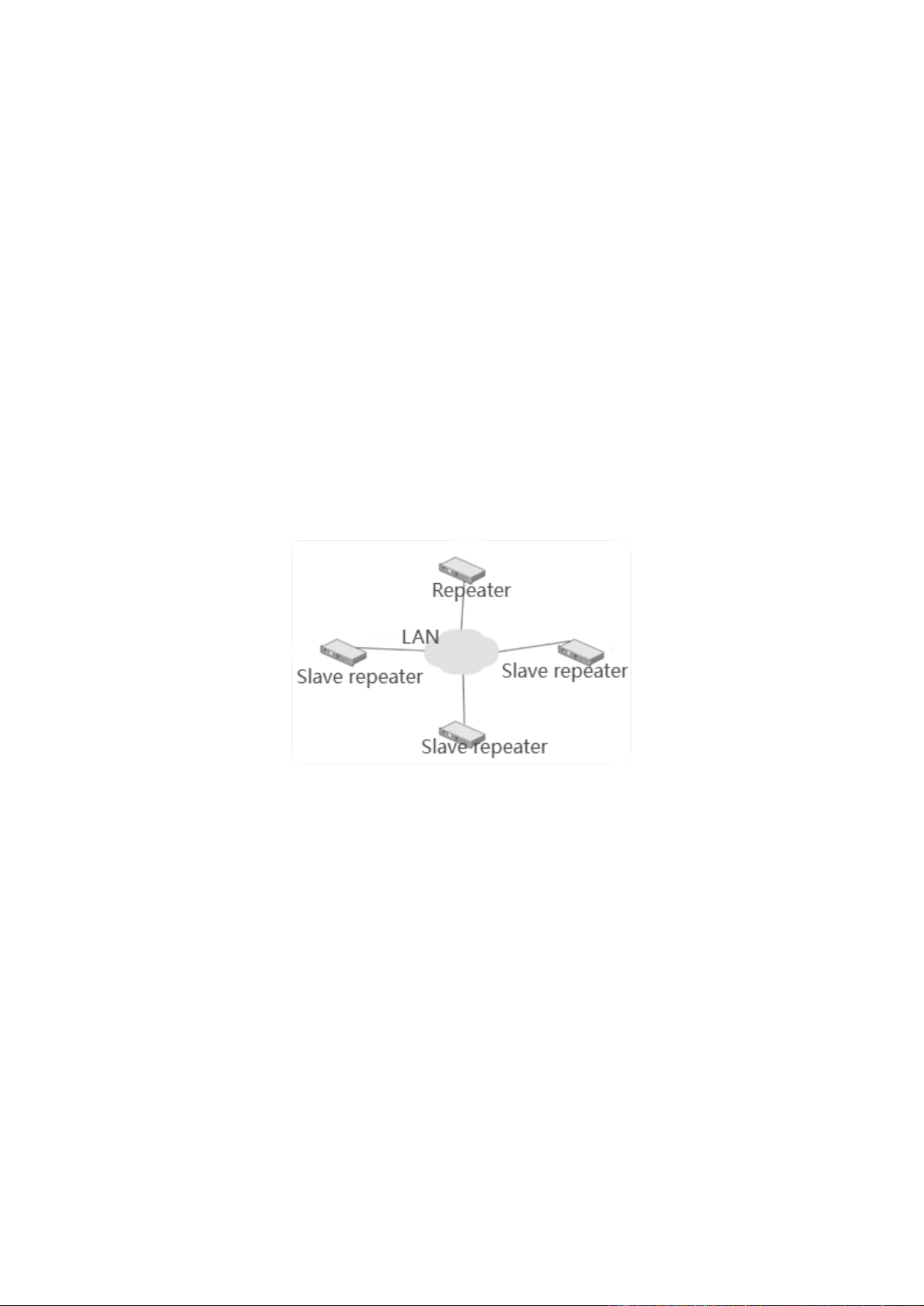
3. Indication of Application Structure
3.1 LAN
The IP connection mode supports the following types of LAN:
Private LAN.
Company LAN.
There are many types of LAN configuration. So long as various equipment items are in the same network, or are
connected to other network through internal routers or NAT configuration,the multi-base station IP connection
network system can work well. For the LAN configuration, the bandwidth is not a problem. However, the system
installers can make the system work in the best state only through understanding the bandwidth required by each
multi-base station IP connection network equipment well.
Moreover, only the master repeater needs a static IPv4 address, other repeaters use the dynamic IP.
The following photo is a brief schematic diagram of multi-base station IP connection network equipment
connecting multiple different site locations through LAN.
3.2 WAN
The biggest advantage of multi-base station IP connection network is that, it can connect multiple sites with high
speed like private network through the network provided by Ethernet ISP (Internet Service Provider).
When using the Ethernet connection, the system installers can make the system work in the best state only through
understanding the bandwidth and time-delay problems required by each multi-base station IP connection network
equipment well. They also need to understand the bandwidth and time-delay between each site. For example, if the
distance between each site is far, it is necessary to consider the time-delay problems of the whole connection.
It shall also be noted that, the communication initiated from a repeater will be sent to each repeater in the system.
Supposing there are N repeaters, if the communication data size that the repeater A needs to send to each repeater is
S, then the total data volume that A needs to send externally at the same time is (N-1)*S.
Therefore, it can be known that, the ISP connection bandwidth that a site needs is related to the repeater quantity of
the system. Increasing a repeater will increase the bandwidth demands of all sites.
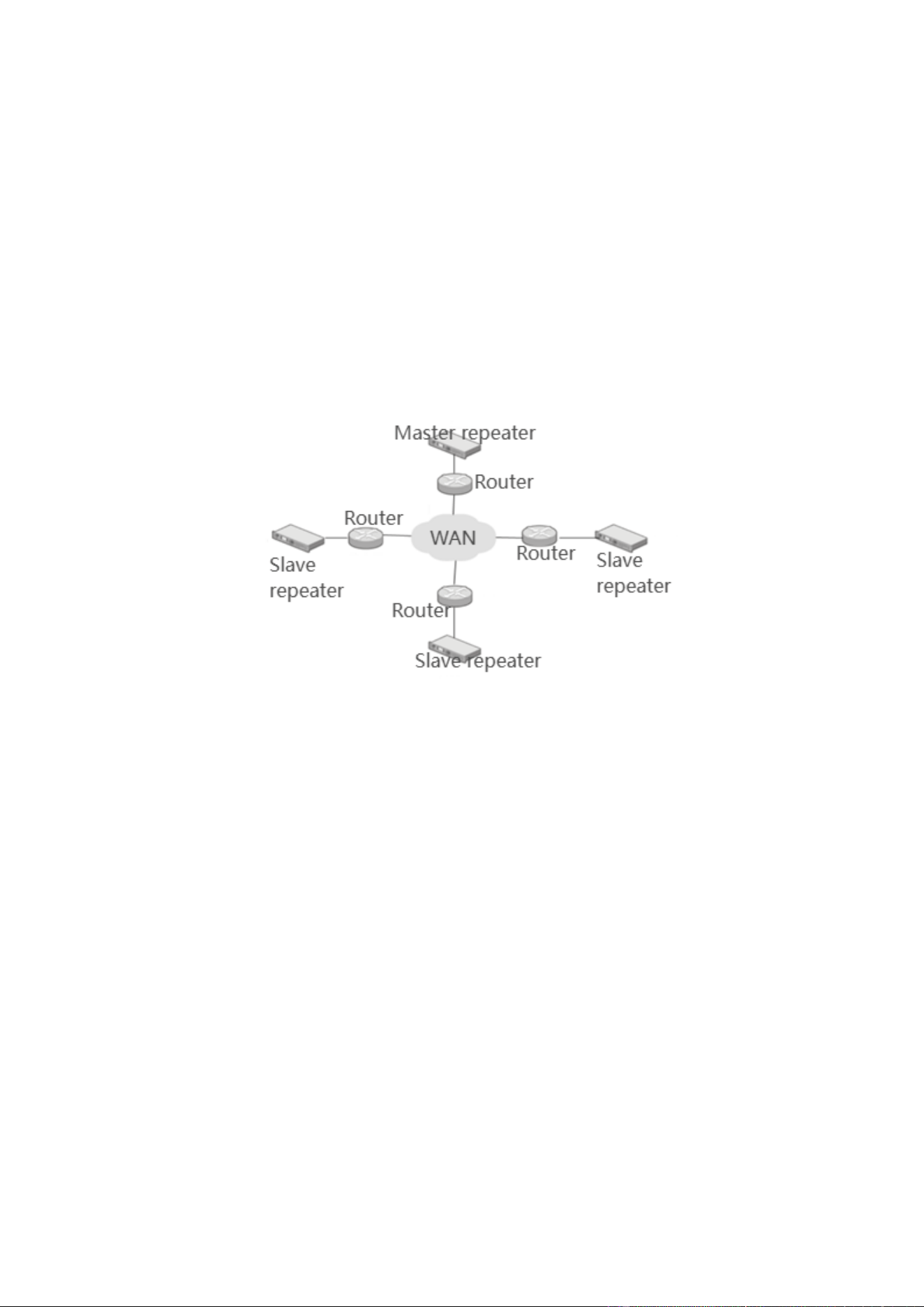
For the sake of safety, it is suggested to connect the repeaters to the routers, NAT or firewalls, and then connect the
repeaters to the WAN through the routers, NAT or firewalls. The repeaters can be connected to the multi-base
station IP connection system through most routers/NAT/firewall equipment.
The multi-base station IP connection network also supports the safe VPN (Virtual Private Network). The safe VPN
is not a function of multi-base station IP connection network equipment, but a function provided by router. It shall
be noted that, VPN will not increase the bandwidth demands, but may cause extra delay.
Only the master repeater needs a static IPv4 address. Other multi-base station IP connection network equipment can
be connected to the wide area system through using the static address accessed by Ethernet. Moreover, it is
necessary to make extra configuration (open the ports) for the routers/NAT/firewalls connected to the master
repeater, then the unsolicited messages sent from other repeaters can be delivered to the master repeater.
The following photo is a brief schematic diagram of multi-base station IP connection network equipment
connecting multiple different site locations through WAN
3.3 WAN and LAN
Most network topologies are jointly composed of LAN and WAN. For example, it may be necessary to connect the
LAN of two or more sites through an ISP, or connect one or more remote sites to a network.
The quantity of multi-base station IP connection network equipment connecting to a WAN has great influence on
the bandwidth of WAN connection. The bandwidth of WAN connection must be greater than or equal to the sum of
bandwidth required by all IP equipment connected to the routers. In other words, if three multi-base station IP
connection network equipment items use an independent ISP connection, the bandwidth of this ISP connection
must be greater than or equal to the sum of bandwidth required by such three equipment items, then such three
equipment items can be supported simultaneously. The data sent from a repeater will be sent to all other repeaters;
therefore, the ISP bandwidth of a site must be greater than or equal to the sum of bandwidth of other sites in the
system. Increasing a repeater in the system will increase the bandwidth demands of all sites.
Similar with the WAN configuration, only the master repeater needs a static IPv4 address. Other multi-base station
IP connection network equipment can be connected to the wide area system through using the static address
accessed by Ethernet. In the same LAN, the multi-base station IP connection network equipment believes that the
repeater with static IP address is the master repeater.
Similarly, it is necessary to make extra configuration (open the ports) for the routers/NAT/firewalls connected to
the master repeater, then the unsolicited messages sent from other repeaters can be delivered to the master repeater.
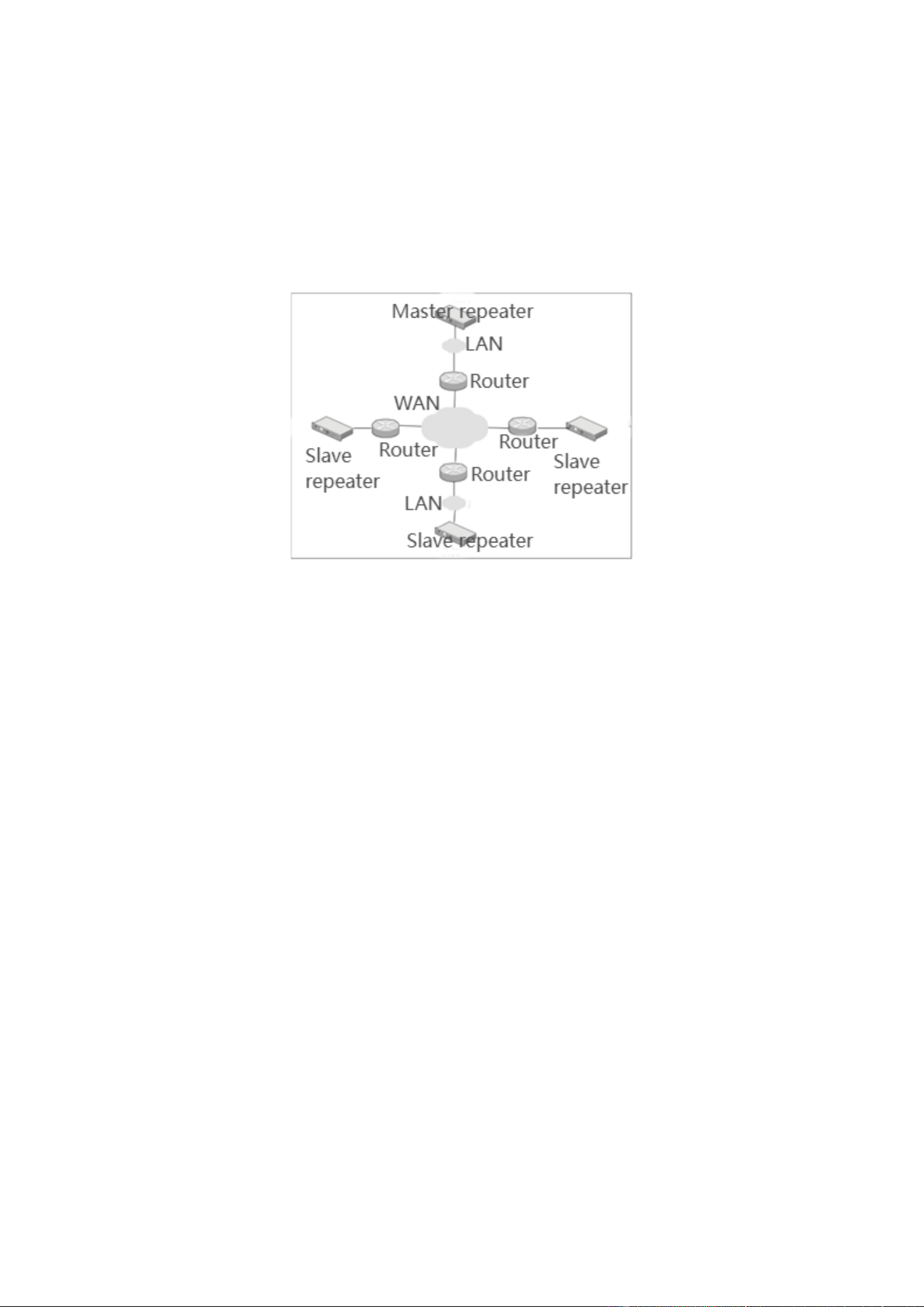
To make the multi-base station IP connection network equipment in the LAN communicate with other equipment
through the WAN IPv4 address, such routers in the WAN must support the “HairPinning” function, which will
return a piece of information to the message source address for indicating how to reach the final destination.
The following photo is a brief schematic diagram of multi-base station IP connection network equipment
connecting multiple different site locations through WAN and LAN.
4. Equipment Connection and Configuration
The terminal equipment in this section shall include the handheld terminals and vehicle terminals.
4.1 Configuration Tools
To realize the IP connection schemes, the corresponding configuration schemes shall be selected according to the
network topology and actual application situations. The configuration of a WAN and LAN comprehensive IP
connection scheme will need the configuration of many parameters, which mainly involve the following types:
Terminal parameters (configure through CPS)
Repeater parameters (configure through CPS)
Switching/routing parameters (configure through related configuration methods of switching/routing equipment)
The switching/routing equipment shall include the switches, firewalls, NAT and routers. The selection of different
switching/routing equipment will have different configuration. For the detailed configuration, please consult the
equipment providers.
4.2 Direct Network Cable Connection
The simplest multi-base station IP connection network can be realized by connecting two repeaters back to back,
this is, two repeaters are connected directly by use of crossover cables. This system configuration scheme is
generally used to demonstrate the principles of network connection, or is used for cross band communication of
terminals.
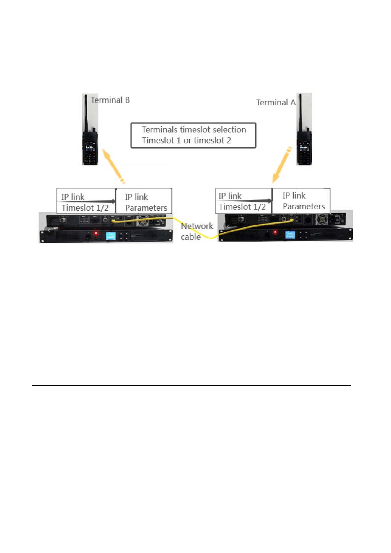
4.2.1 Hardware Connection
This scheme realizes the IP connection by connecting two repeaters directly with the crossover. The limitation of
this scheme is that, only two repeaters can be connected and the expanding physical space is limited.
4.2.2 Terminal Programming Configuration
The use of terminals in the IP connection is same with that in single repeater, so the terminal parameter
configuration can refer to its application configuration in single repeater.
The terminal programming parameter configuration for realizing the IP connection is as below:
Configure the terminals according to the requirements for use in single repeater.
The “Timeslot Selection” parameter must be configured, otherwise the terminals can only work in the direct
mode operation. The selection of “Timeslot 1” and “Timeslot 2” in this parameter shall correspond to the IP
connection parameters of the repeater, otherwise different communication effects will be caused, as shown in the
Table below:
Terminal timeslot Repeater IP connection
timeslot
Results
Timeslot 1 Timeslot 2
The terminals cannot realize the IP connection, so the
terminals can only work in the current single repeater, and
the realized communication can only aim at the range of
current single repeater.
Timeslot 1 or
Timeslot 2
None
Timeslot 2
Timeslot 1
Timeslot 1 Timeslot 1 or Timeslot
1&Timeslot 2
The two timeslots can correspond, and the terminals can
realize the IP connection, so the terminal can communicate
within the repeater connection range.
Timeslot 2
Timeslot 2 or Timeslot
1&Timeslot 2
The “color code” of terminals must be same with the “color code” of registered repeaters, otherwise the terminals
cannot be used in the system.
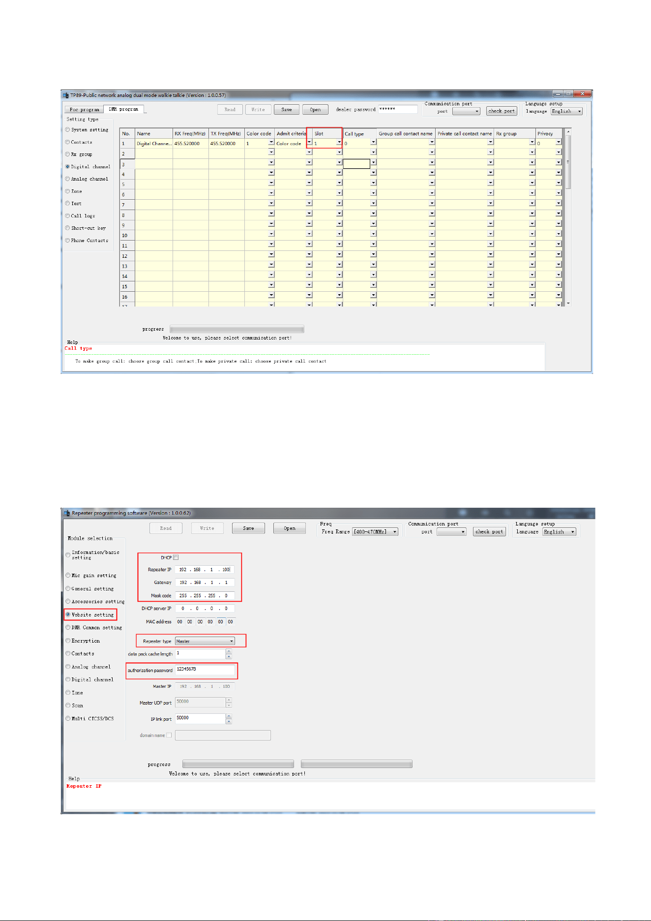
The portable radio configuration is shown in the photo Below (with TP-89 as an example):
4.2.3 Repeater Programming Configuration
Configure the master repeater
Step 1: Configure the communication parameters of master repeater through CPS, such as frequency and color
code.
Step 2: Configure the IP connection parameters.

Parameter name
Introduction
IP related parameters
DHCP Not checked. The IP configuration of the master repeater cannot use the DHCP way,
because the master repeater needs a fixed IP to facilitate the registration of Slave repeaters.
Local IP
It is the IP address of the repeaters.
When adopting this scheme, the master repeater must use the static IP, otherwise the Slave
repeaters cannot be connected to the master repeater. The static address of the master
repeater must be must be unique in the system.
Gateway
It is the gateway IP of the subnet where the repeater is located.
Mask
It is the subnet mask of the subnet where the repeater is located.
Master repeater role parameters
Repeater type For the master repeater, please set it as “Master”; for the Slave repeater, please set it as
“Slave”.
Data packet buffer
length
It is the buffer area size when buffering voice or data from the network. When the network
state is poor, i.e. when the network jitter is severe, increasing the buffer area size can
improve the continuity of calls. For every increase of 1 in this length, the reception of
voice or data will be delayed by 60ms.
Please use the default values. The non-professionals shall not modify the values of this
parameter.
Authorization
password
It is used to prevent illegal access of repeaters under other IP connection systems within
the same LAN.
The repeaters under the same IP connection system use this authorization password for
authentication.
IP connection port
It is the IP networking UDP port, which is used for establishing and maintaining network
connections between master repeater and Slave repeaters. Please use the default values.
Note:
In the system with direct network cable connection, the subnet parameters can be set freely, but all repeaters in the
system must be consistent.
An abstract gateway address is input in the “Gateway” position. In this configuration, although there is no gateway,
a gateway address is still need to input.
This address must be unique in the system, and it is suggested that the last digit shall not be set to zero.
Step 3: Select the work timeslot for accessing IP connection network according to actual needs.
In order to ensure the smooth progress of cross-network communication, please ensure that all repeaters use
the same IP connection timeslot in the same IP connection system.
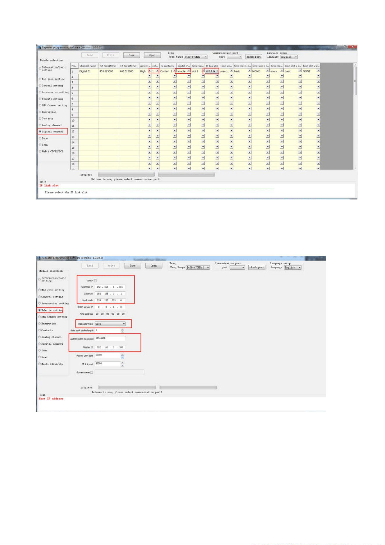
Configure the Slave repeaters
Step 1: Configure the communication parameters of Slave repeaters through CPS, such as frequency and color
code
Step 2: Configure the IP connection parameters.
Do not check DHCP.
For the Slave repeater, it is necessary to input an unused subnet static address, and ensure that it is in the same
subnet as the master repeater.
Local IP (192.168.1.101): The static address of Slave repeater must be unique in the system.
Gateway (192.168.1.1): Keep consistent with that of the master repeater.
Mask (255.255.255.0): Keep consistent with that of the master repeater.
Set the “Repeater type” as “Slave”.
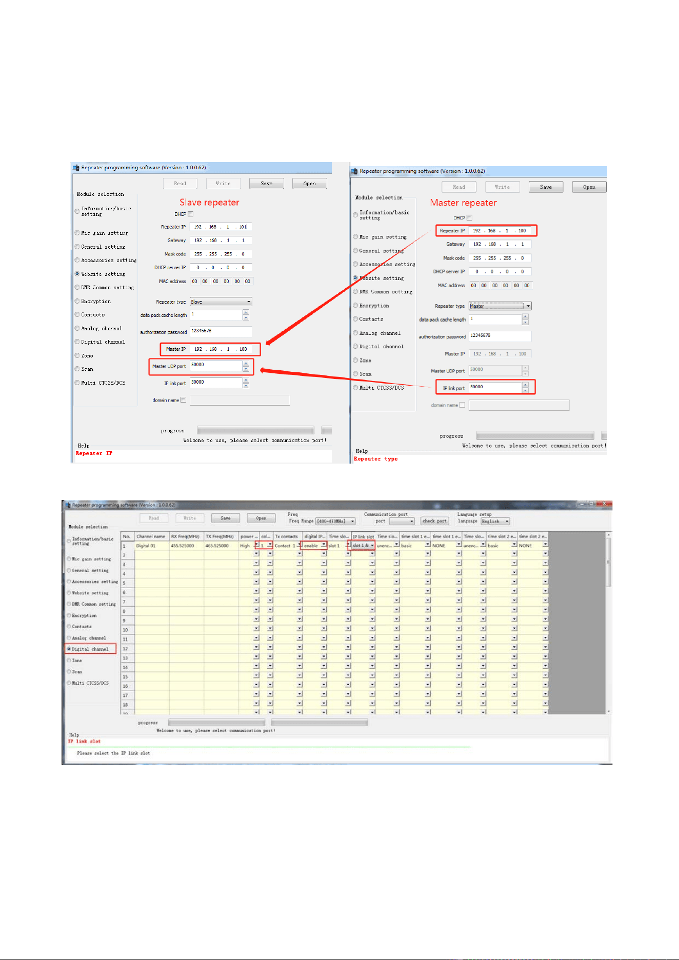
Input the IP address of master repeater in the “Master IP address” position, and input the IP connection port of
master repeater in the “Master UDP port” position.
Set the “IP connection port” to be any unused local port. The value range is 1024~65535. Please use the default
values.
Corresponding schematic diagram for parameters of master repeater and Slave repeaters
Step 3: Configure the IP connection work timeslot same with the master repeater.
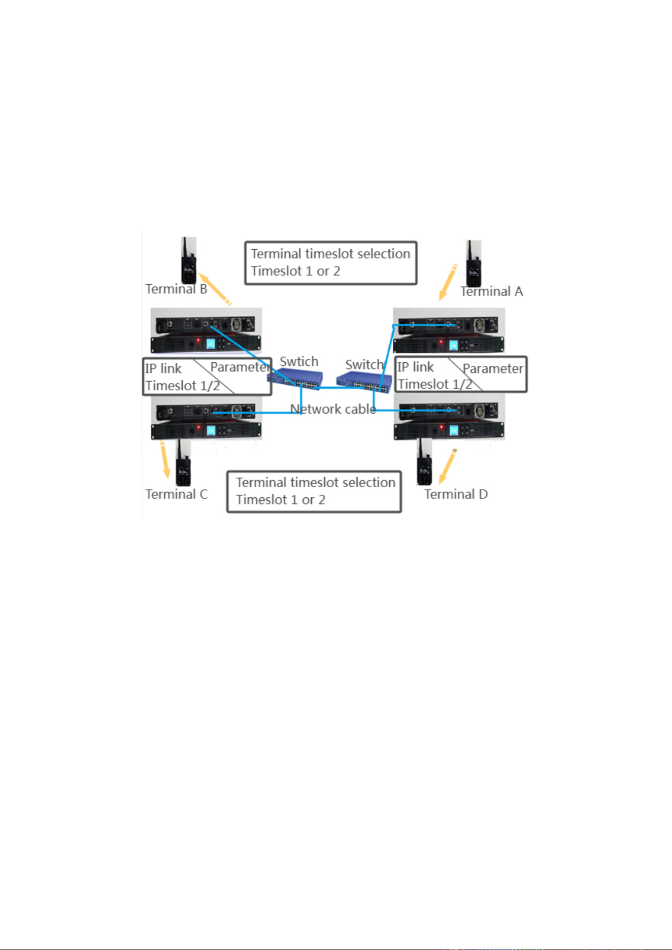
4.3 Switch Connection in the LAN
4.3.1 Hardware Connection
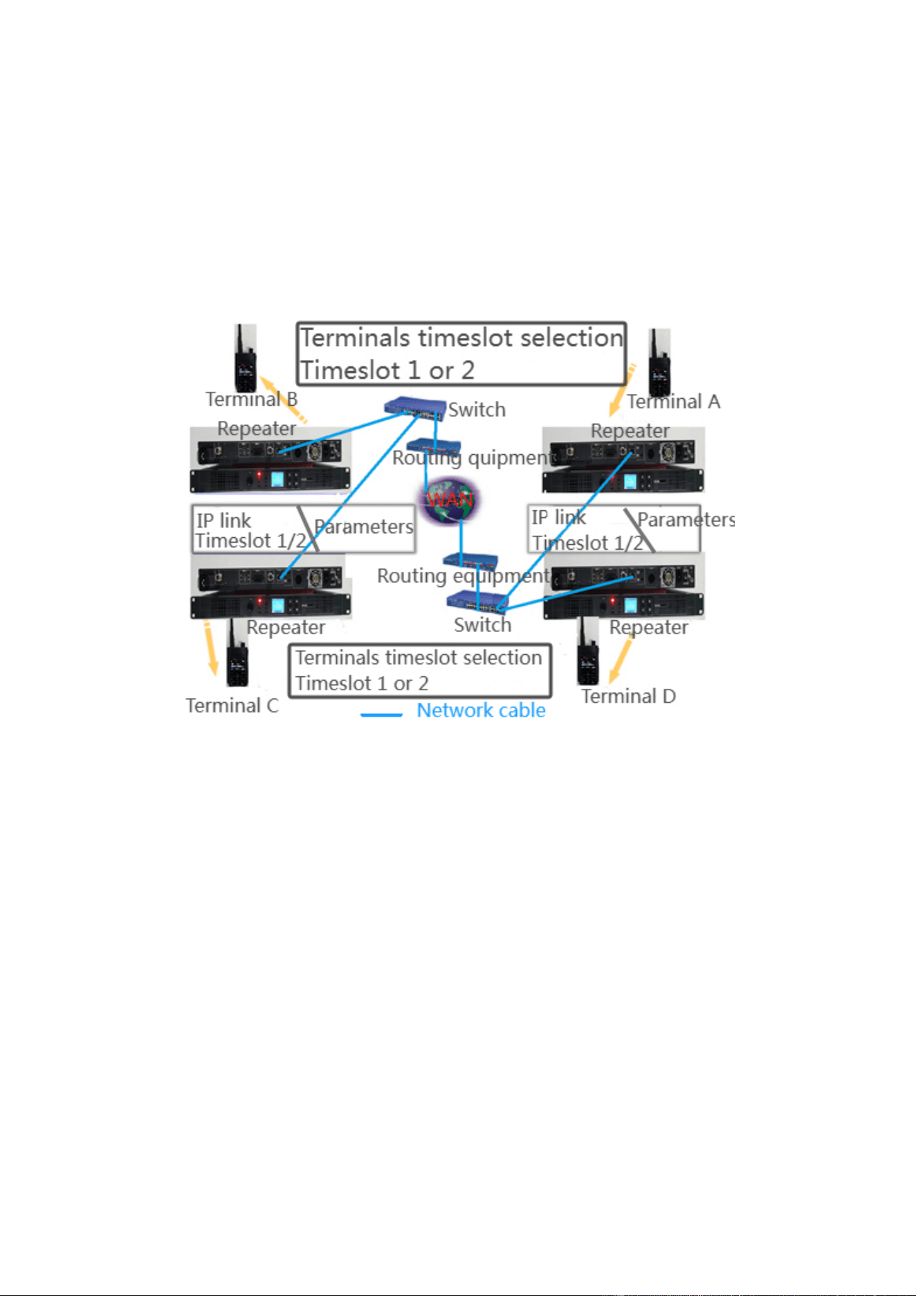
This scheme is used for the IP connection scheme of one or more switches in the LAN. This scheme is mainly
applied for the connection and interworking in the same area. The schematic diagram of connection through
switches in the LAN is as below:
4.3.2 Terminal Programming Configuration
In this connection way, the configuration of terminals is same with that in the direct network cable connection way.
For specific operations, please refer to the 4.2.2 Terminal Programming Configuration.
4.3.3 Repeater Programming Configuration
The simplest method for IP multi-base station connection in the LAN is to connect through a switch. Same as the
crossover cable direct connection, this is also a back-to-back scheme.
The advantage of this back-to-back scheme is increasing the IP access equipment.
Configure the master repeater
In this configuration scheme, the configuration of the master repeater is same with that in the cable direct
connection scheme. When configuring, please note the following 2 points:
1. The master repeater shall be configured with the network authorization password to prevent the illegal access
of repeaters under other IP connection systems in the same LAN.
2. This LAN can have the DHCP server allocate IP address automatically, or use the static IP address. However, the
master repeater can only use the static IP address (not checking DHCP).
When the DHCP server allocates the IP address automatically, in order to prevent the address conflict, any static IP
address allocated to the repeaters cannot be within the IP address range allocated dynamically by the DHCP server,
but it must be in the same subnet.
Configure the Slave repeaters
In this configuration scheme, the configuration of the Slave repeaters is similar with that in the cable direct
connection scheme. When configuring, please note the following 2 points:
The “network authorization password” of the master repeater and Slave repeaters must be consistent.
The Slave repeaters can use the static IP address, or have the DHCP server allocate IP address automatically.
Since the automatic allocation of IP address may cause temporary interruption of communication, it is not
suggested to use the IP address range allocated dynamically by the DHCP server.
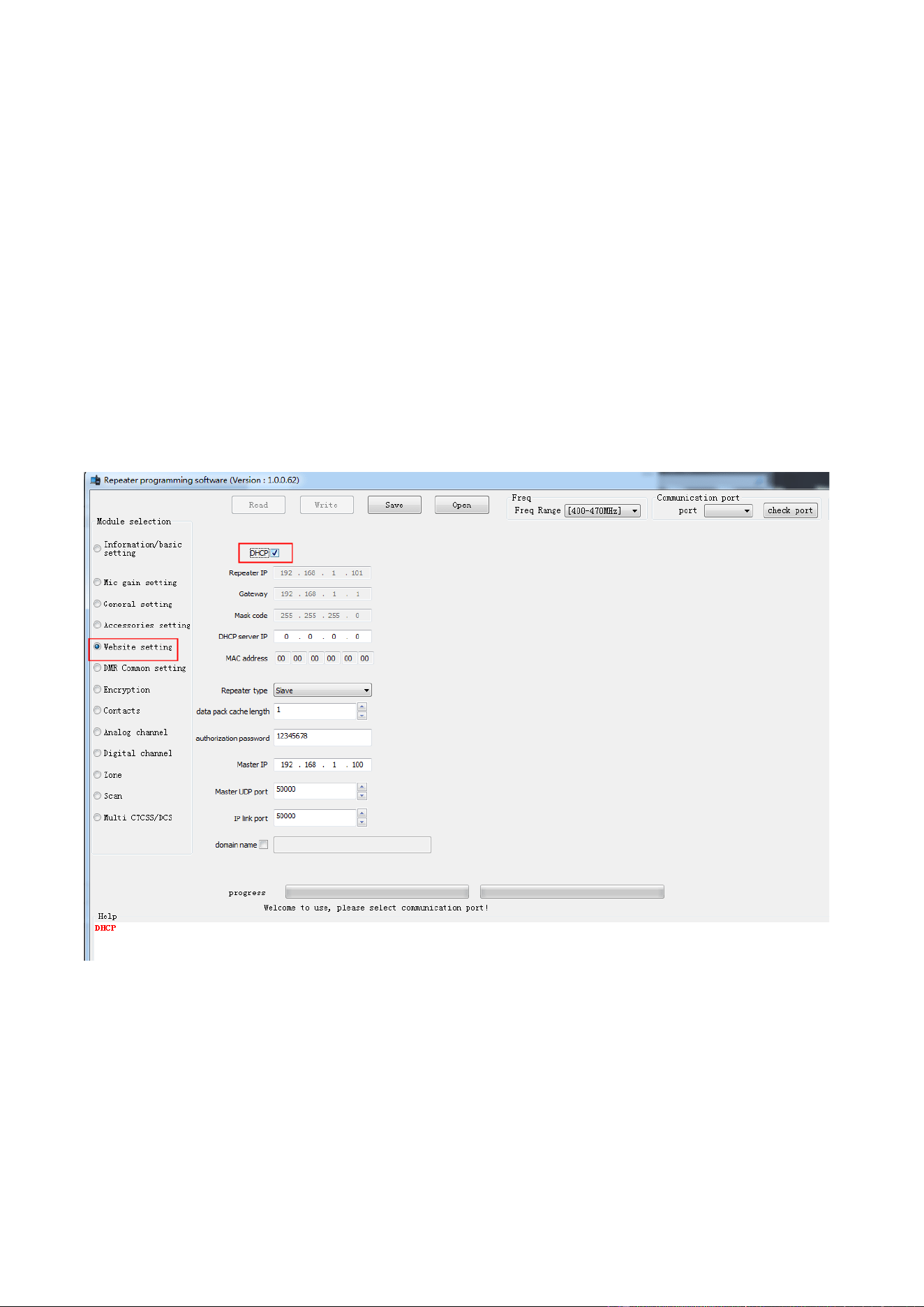
When using the static IP address, its configuration is same with that of Slave repeaters in the cable direct
connection; when the DHCP server allocates the IP address automatically, the “DHCP” must be checked, but
“Local IP”, “Gateway” and “mask” do not need to be configured, as shown in the photo below. For the
configuration of other parameters, please refer to the “Configure the Slave repeaters”.
4.3.4 Switching Equipment Configuration
When selecting different switching equipment, the configuration is also different. For specific configuration steps,
please consult the equipment providers.
4.4 Switching Connection between WANs
4.4.1 Hardware Connection
This scheme is applicable for the IP connection scheme of cross-regional multi-site connection. The key equipment
of this scheme is “routing equipment”. Through the routing equipment, multiple repeater equipment in different
space positions can be connected to realize the IP connection of WAN.
4.4.2 Terminal Programming Configuration
In this connection way, the configuration of terminals is same with that in the direct network cable connection way.
For specific operations, please refer to the 4.2.2 Terminal Programming Configuration.
4.4.3 Repeater Programming Configuration
In actual applications, the most common multi-base station IP connection system includes multiple LANs and
WANs connected by routers. The typical application is public network, which is to connect multiple LANs to
WAN though the ADSL way by the network service providers. The IP connection network will cause certain delay.
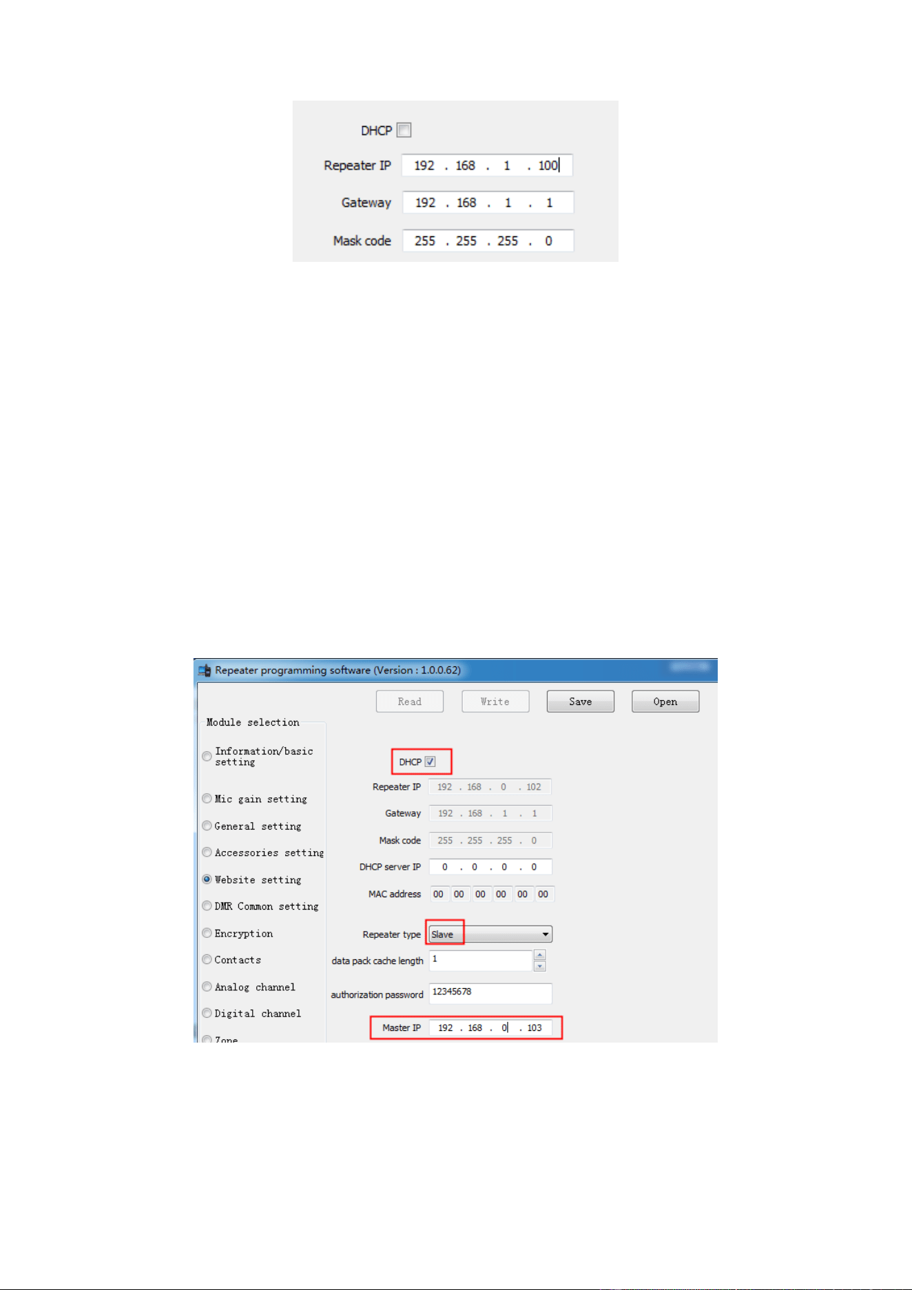
Configure the master repeater
The IP address configuration of the master repeater is shown in the photo below, indicating the static IP of LAN 1
in WAN connection and interworking through routing equipment.
In order to reduce the costs of the IP connection system, the master repeater can also use a domain name instead of
configuring a static IP address. The user can apply for a domain name for the master repeater, and then bind this
domain name with the master repeater.
The “Local IP” of the master repeater (such as the IP address of the master repeater) cannot be within the address
pool range of the DHCP server, but it shall still belong to the same subnet (whether it is in the same subnet shall be
determined by the gateway and subnet mask of LAN), so the gateway IP needs to be configured according to the IP
address of router in the LAN 1.
Since all equipment items are in the subnet of various routers, and such addresses in LANs are unidentifiable in
WANs, the routers of LAN 1 must be configured with “Port mapping”, and forward the packages received from the
router WAN side designated ports directly to the master repeater.
Configure the Slave repeaters
All Slave repeaters can use the static IP address, or be configured to obtain the IP address from the DHCP server in
respective LAN. However, the latter is not suggested to use.
The “Master IP address” of all Slave repeaters must be input with the WAN address of master repeater. i.e. the
WAN address of LAN 1 router.
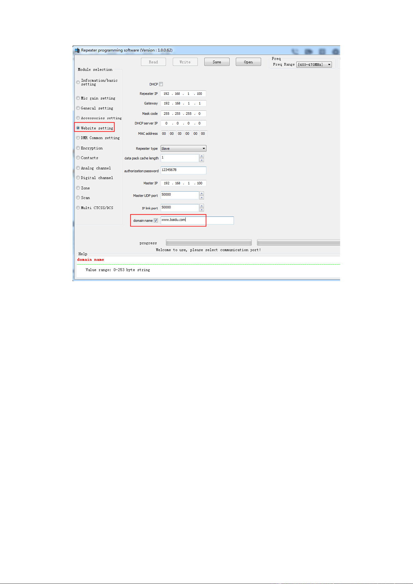
When the master repeater has been bound with a domain name, the Slaves do not need to be configured with the IP
of master repeater, but just need to open the “master domain name on/off”, and be input with the domain name of
master repeater (the following screenshot takes “www.baidu.com” as an example), as shown in the photo below.
In the above configuration, the WAN side UDP port and the master repeater use the same UDP port. If the WAN
side UDP port is not same with the master repeater UDP port, the master UDP port of all Slaves must be modified
as the WAN side UDP port.
For the configuration of other parameters, please refer to “Configure the Slave repeaters”.
Under this configuration, the following points shall be noted:
It is unnecessary to configure the “Port mapping” for the Slaves, because the routers which the Slaves belong to
will complete this process automatically. Not all routers support the function of “Port mapping”.
When the Slave repeaters connecting the master repeater, the master repeater shall notify the public network
address to the other Slave repeaters.
When configuring the UDP ports, many Slaves in the same LAN do not need to be configured with different port
numbers intentionally, because the routers will be allocated with a sole port number when completing the port
mapping automatically.
The Slaves which are in the same LAN with the master repeater also need to configure the address of master
repeater as the WAN address instead of LAN address, otherwise they cannot be connected with Slaves in other
LANs.
In the above configuration, the routers of LAN 1 and LAN 2 must support the “HairPinning” function. The
“HairPinning” can ensure that, when accessing equipment in the same LAN by use of WAN addresses and ports,
they will not be replaced with subnet addresses, thus result in connection failure.
Some routers may only support “HairPinning” function partially. This may cause the Slave repeaters in the same
LAN with the master repeater have connection problems, but still support other Slave repeaters in different LANs
with the master repeater stay in the same LAN.

Some private networks (such as Intranets) have the capabilities of finding the IP addresses of all equipment. When
the equipment is connected to such network, the DHCP server will allocate the IP addresses to the equipment, and
adjust the routers automatically, so as to ensure mapping the packet routing to the correct master. The master
repeater still needs a static IP address.
4.4.4 Switching Equipment Configuration
Different switching equipment have different configuration. Therefore, for parameter configuration of switching
equipment, please consult the equipment providers.
4.4.5 Routing Equipment Configuration
Different routing equipment have different configuration. Therefore, for detailed description on parameter
configuration of routing equipment, please consult the equipment providers.
5. Common Problems
5.1 In the connection network, if the network of some repeater is
interrupted, whether other repeaters still can work normally?
Once multiple repeaters are networked successfully, the network problem of any repeater in the network will not
influence other repeaters. The reason is, the whole networking is similar with the Slave-to-Slave network, and the
role of master repeater is to register and broadcast the address. If any Slave repeater gets offline, the master repeater
will detect it and notify all other Slave repeaters; if the master repeater gets offline, the remaining Slave repeaters
can still continue to work, but cannot join in the new Slave repeaters, or know whether there are other Slave
repeaters getting offline, until the master repeater recover again.
5.2 In the IP connection network, how to select the frequency and color
code?
In different system topologies, the user can select different configuration demands according to own needs.
Generally speaking, it is suggested to use different frequencies for the repeaters in the areas where overlapping
coverage may occur. Their color codes may be same or different. However, if the adjacent repeaters need to use the
same frequency, it is best for them to use different color codes, because using the same frequency and color codes
under the situations with overlapping coverage will cause interference issues. Therefore, in order to ensure the
user’s normal communication demands, it is not suggested to use the same frequency and color codes for the
adjacent repeaters in the overlapping coverage range.

5.3 When the multi-base station IP connection network system is
networked, which problems need to be considered generally?
The establishment and configuration of network shall be determined by the equipment and IP connection network
system. Since the networking environment may be complex, it’s best to get the assistance of local network
configuration administrators.
Some notable common problems are listed below:
It is suggested to ensure the statically allocated IP addresses not causing conflicts. The conflicting IP addresses will
cause the multi-base station IP connection network to have communication interruption. In case of using DHCP,
it’s best to have the statically allocated IP addresses out of the allocate-able address range, so as to avoid DHCP
allocating the conflicting IP addresses.
If other network equipment as multi-base station IP connection network equipment appears in the same IP
connection network, in order to ensure the communication quality of multi-base station IP connection network, it is
suggested to establish the QoS (Quality of Service) rules in the Ethernet routers, and improve the priority of
multi-base station IP connection network communication and sufficient reserved bandwidth.
It is suggested to ensure the user network firewalls will not limit the multi-base station IP connection network UDP
ports, otherwise they may obstruct the IP addresses or UDP ports used by multi-base station IP connection network.
For details, please consult the local network configuration administrators or Ethernet service providers.
When selecting the Ethernet service providers, it’s best to select the service providers without traffic limit. Since
the multi-base station IP connection network system transmits voice on the Ethernet, for high load systems, it is
possible to exceed the traffic limit of this service provider. For example, the standard load of IP connection network
system with 5 repeater sites needs about 20GB traffic per month, but a system with 15 sites may need about 65GB
traffic per month.
5.4 How to calculate the required bandwidth size?
The data sent by each repeater in the multi-base station IP connection network system is far greater than the
received data volume. Therefore, the required bandwidth is calculated generally according to the sent data. In the
dual-timeslot communication, plus some additional data for maintaining the network, the data volume sent to a
repeater is about 70Kbps. If there are N repeaters for networking, in the dual-timeslot work, each repeater needs to
send data to N-1 repeaters, so the overall bandwidth demands are: (N-1)*70 Kbps.
5.5 How many repeaters can be contained in the single WAN system?
In view of the DMR protocol, generally a timeslot is 30ms (dual-timeslot is 60ms). In the IP connection network,
each repeater needs to send all voices or data to all other repeaters within 30ms time. Moreover, the system
approximately needs to reserve about 30% time to run other tasks, i.e. complete sending of voices or data within
about 21ms. On basis of such design conditions, the repeater volume of our system cannot exceed the number of
30.
5.6 When connecting and networking by adopting the LAN, which
matters need to be considered?
When it is unnecessary to make port mapping, the internal network does not need the static IP addresses, and the
Slaves can adopt the DHCP protocol to obtain the dynamic IP automatically. When it is necessary to make port
mapping, both the master repeater and Slaves need the static IP addresses, and need to map the IP connection UDP
ports, thus connect the master repeater and other Slaves, and realize various businesses.
Whether to make port mapping is also relevant with the chosen routers. When the IP connection network fails, the
user needs to make port mapping. If the recommended routers are used, the port mapping is not required, and the
Slaves do not need the static internal network IP connection
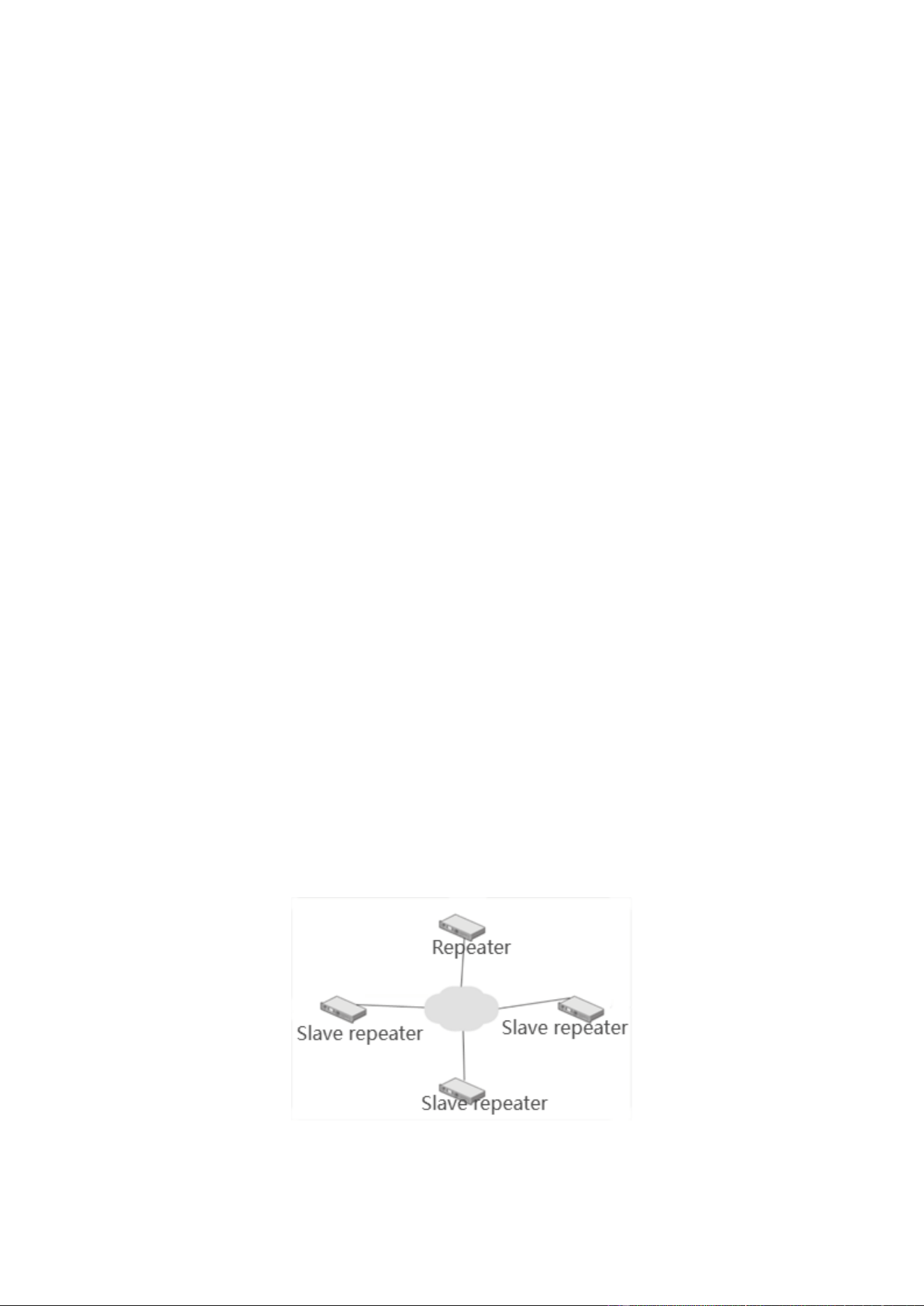
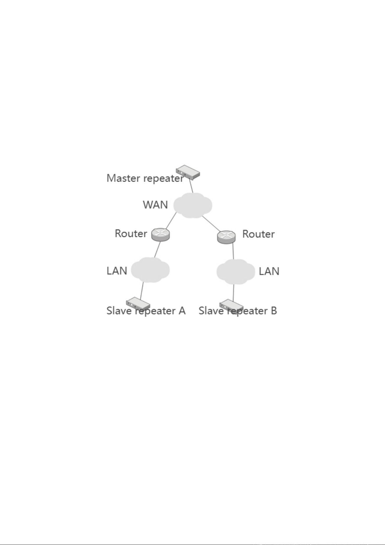
As shown in the above photo, the Slave A and the Slave B are distributed in different LANs, and the two LANs are
in different networks. If it is necessary to make port mapping, the Slave must have a static internal network IP
address, and make port mapping through a router, so as to realize the connection with the master repeater and other
Slaves. For the port mapping setting methods, please refer to the use instructions of chosen routers.
Since the direct designation of IP addresses may cause the situations of conflicting with the IP addresses of other
equipment in the LAN, the user may also adopt the DHCP protocol to obtain the static IP addresses. When
obtaining the static IP addresses through the DHCP protocol, the equipment MAC addresses and IP addresses must
be bound in the router. For specific setting methods, please refer to the use instructions of chosen routers.

5.7 Learn the role and cautions of data packet buffer length. What is
the influence of network transmission delay on call quality, and how to
solve?
The IP connection functions adopt the UDP protocol in the transmission layer. The UDP protocol is a protocol used
for internal Slave-to-Slave services (P2P), and its transmission data does not have the confirmation and
retransmission mechanism. During the transmission process, when sending out a UDP data packet from the same
node position, the destination node and the intermediate node are different, so the data packet transmission jitter
and disorder may occur. In case of poor network state, when the factors such as communication conflict, network
resource preemption or bandwidth limit occur, the situations of data packet loss may occur.
The data packet buffer length functions can reorder and buffer the UDP data packet, and then send after a time
interval. The terminals adopt the TDMA technology to transmit signals, and the transmission and reception of
frames are of equal time intervals, so sending data packets after a certain time interval will not affect the signals.
If the difference between the time when a UDP data packet is sent from the starting node to the receiving end and
the time when the previous UDP data packet arrives is greater than a threshold value, it is deemed that this UDP
data packet is lost. The buffer time of buffer length shall be greater than this threshold value, and the user can set
the buffer time according to the number of data packet buffer length.
The buffer time value range of data packet buffer length is: 1*60~8*60 ms, default value 1*60 ms.
When setting the data packet buffer length, the user shall set according to the actual transmission quality of network.
When the buffer queue length number is too small, the buffer data packet number is small, and the case of large
network delay cannot be tolerated; when the buffer queue length number is more, the buffer UDP data packet
number is more, and the tolerable network delay is larger, but the intermediate transmission time is also larger. The
too small buffer queue length number cannot solve the problems of data packet loss. The increase of buffer length
number can relieve the problems of UDP data packet transmission loss to some extent, but it also increases the
delay of network transmission, which will cause certain influence on some digital communication for confirmation.
Therefore, the buffer queue length number shall be set according to actual network state.
At present, the network delay is mainly measured by use of ping command. In the LAN or private network, the
network delay is generally less than 60ms, so the default buffer length can be used. In other network environment,
when the tested network delay is greater than 60ms, it is necessary to adjust the data packet buffer length
accordingly. When using the IP connection functions through the WAN, the problems of bandwidth and resource
preemption may cause severe jitter, delay even loss in UDP data, which cannot be solved completely solely through
the setting of data packet buffer length. If the user has high requirements for call quality, it is suggested to use the
public network with higher quality, and even erect private network when necessary.
5.8 What are the influences on call quality when the voice data packet
transmission delay or lost?
In the IP connection mode, when the voice data packet loss occurs during the network transmission process, the
repeater will fill the mute frames for transmission, then the terminal voice will have the phenomena of

intermittence. If two consecutive voice superframe data packets are lost, the repeater will think this call is abnormal,
and end this call automatically. If the new voice data packet or call request is received at this time, the intermediate
transmission will process again.
When the digital business has data packet delay, and the delay time exceeds the time length set by the buffer length,
the data packet loss will occur, and the digital communication will have the situations of confirmation
unavailability or failure.
5.9 What are the recommended brands and models of routers and
switches?
Router: CISCO 1841, and CISCO 2801
Switch: H3C S2 series
6.0 Statements warning and compliance statement
CE statement
We declare that the radio is compliance with Radio equipment Directive (RED) 2014/53/EU.
The full text of the EU declaration of conformity is available at the following internet address: xxxxxx
The device in the environment with the temperature between 0-55℃. and operating under 2000m, otherwise, it may
damage your device.
This equipment complies with RF radiation exposure limits set forth for an uncontrolled environment. This
equipment shall be installed and operated with minimum distance 125 cm between the radiator & body.
Prohibit the use of non-original antenna, if the antenna is damaged, please contact the dealer for replacement,
support the frequency range of 400-470MHz external antenna gain 0dBi max /50 ohms.
Prohibit the use of non-original antenna, if the antenna is damaged, please contact the dealer for replacement,
support the frequency range of 136-174MHz external antenna gain 3dBi max /50 ohms.
CAUTION:
RISK OF EXPLOSION IF BATTERY IS REPLACED BY AN INCORRECT TYPE. DISPOSE OF USED
BATTERIES ACCORDING TO THE INSTRUCTIONS.
This device is restricted to indoor use only when operating in 5150 MHz to 5350 MHz in all EU member states.
FCC statement
This device complies with part 15 of the FCC Rules. Operation is subject to the condition that this device does not
cause harmful interference. The grantee is not responsible for any changes or modifications not expressly
approved by the party responsible for compliance. Such modifications could void the user’s authority to operate the
equipment. Replacement of any transmitter component (crystal, semiconductor, etc.) not authorized by the FCC
equipment authorization for this radio could violate FCC rules.
Note: This equipment has been tested and found to comply with the limits for a Class B digital device, pursuant to
part 15 of the FCC Rules. These limits are designed to provide reasonable protection against harmful interference
in a residential installation.

This equipment generates, uses, and can radiate radio frequency energy and, if not installed and used in accordance
with the instructions, may cause harmful interference to radio communications. However, there is no guarantee that
interference will not occur in a particular installation.
If this equipment does cause harmful interference to radio or television reception, which can be determined by
turning the equipment off and on, the user is encouraged to try to correct the interference by one or more of the
following measures:
Reorient or relocate the receiving antenna.
Increase the separation between the equipment and receiver.
Connect the equipment into an outlet on a circuit different from that to which the receiver is
connected.
Consult the dealer or an experienced radio/TV technician for help.
This radio transmitter has been approved by FCC to operate with the antenna types listed below with the maximum
permissible gain and required antenna impedance for each antenna type indicated. Antenna types not included in
this list, having a gain greater than the maximum gain indicated for that type, are strictly prohibited for use with
this device.
This equipment complies with FCC radiation exposure limits set forth for an uncontrolled environment. This
equipment shall be installed and operated with minimum distance 185cm between the radiator& body.
For USA: The frequency stability of all transmission frequencies of U-NII-1, U-NII 2A, U-NII 2C and U-NII-3 me
ets the requirements of 47 CFR FCC Part15.407(g), and the manufacturer declares that their transmission is maintai
ned at Band U-NII-1, U-NII 2A, U-NII 2C and U-NII-3.
WARNING: MODIFICATION OF THIS DEVICE TO RECEIVE CELLULAR RADIOTELEPHONE SERVICE
SIGNALS IS PROHIBITED UNDER FCC RULES AND FEDERAL LAW

Technical Description
MD-7500 UHF EU Version
Operating
Mode
Frequency
(MHz)
Antenna Gain
(dBi)
Max Output Power
(W)
GPRS 900 880-915 1.37 1.866
GPRS 1800 1710-1785 2.64 0.843
UMTS B1 1920-1980 1.87 0.218
UMTS B8 880-915 1.37 0.222
LTE B1 1920-1980 1.87 0.215
LTE B3 1710-1785 2.64 0.189
LTE B7 2500-2570 2.12 0.177
LTE B8 880-915 1.37 0.186
LTE B20 832-862 0.48 0.183
LTE B28 703-748 0.48 0.203
LTE B38 2570-2620 3.05 0.193
LTE B40 2300-2400 3.52 0.204
LTE B41 2496-2690 3.6 0.178
Bluetooth BR/EDR 2402-2480 - -
Bluetooth BLE 2402-2480 - -
2.4G WIFI 2412-2472 -3.8 0.023
5G WIFI
5150-5250
5250-5350
5470-5725
5725-5850
-2.0 0.020
Mobile Station 400-470 0 40.551
GPS 1575.42 - -
GLONASS 1602 - -
GALILEO 1575.42 - -
BDS 1561.098 - -
FM 87.5-108 - -

MD-7500 VHF EU Version
Operating
Mode
Frequency
(MHz)
Antenna Gain
(dBi)
Max Output Power
(W)
GPRS 900 880-915 1.37 2.234
GPRS 1800 1710-1785 2.64 0.989
UMTS B1 1920-1980 1.87 0.228
UMTS B8 880-915 1.37 0.237
LTE B1 1920-1980 1.87 0.204
LTE B3 1710-1785 2.64 0.205
LTE B7 2500-2570 2.12 0.172
LTE B8 880-915 1.37 0.227
LTE B20 832-862 0.48 0.207
LTE B28 703-748 0.48 0.244
LTE B38 2570-2620 3.05 0.203
LTE B40 2300-2400 3.52 0.213
LTE B41 2496-2690 3.6 0.196
Bluetooth BR/EDR 2402-2480 - -
Bluetooth BLE 2402-2480 - -
2.4G WIFI 2412-2472 -3.8 0.024
5G WIFI
5150-5250
5250-5350
5470-5725
5725-5850
-2.0 0.022
Mobile Station 136-174 3.0 43.855
GPS 1575.42 - -
GLONASS 1602 - -
GALILEO 1575.42 - -
BDS 1561.098 - -
FM 87.5-108 - -

MD-7500 UHF US Version
Operating
Mode
Frequency
(MHz)
Antenna Gain
(dBi)
Max Output Power
(W)
LTE B2 1850-1910 2.0 0.134
LTE B4 1710-1755 2.0 0.139
LTE B5 824-849 1.5 0.165
LTE B7 2502-2568 2.0 0.118
LTE B12 699-716 1.5 0.100
LTE B13 779-785 1.5 0.100
LTE B14 790-796 1.5 0.103
LTE B17 706-714 1.5 0.173
LTE B25 1805-1915 2.0 0.135
LTE B26 814-824 1.5 0.091
LTE B26 824-849 1.5 0.094
LTE B41 2498-2688 2.0 0.130
LTE B66 1710-1780 2.0 0.147
LTE B71 665-696 1.5 0.103
Bluetooth BR/EDR 2402-2480 - -
Bluetooth BLE 2402-2480 - -
2.4G WIFI 2412-2472 -3.8 0.13
5G WIFI
5150-5250
5250-5350
5470-5725
5725-5850
-2.0 0.023
Mobile Station 400-470 3.0 42.657
GPS 1575.42 - -
GLONASS 1602 - -
GALILEO 1575.42 - -
BDS 1561.098 - -
FM 87.5-108 - -

MD-7500 VHF US Version
Operating
Mode
Frequency
(MHz)
Antenna Gain
(dBi)
Max Output Power
(W)
LTE B2 1850-1910 2.0 0.140
LTE B4 1710-1755 2.0 0.148
LTE B5 824-849 1.5 0.100
LTE B7 2502-2568 2.0 0.126
LTE B12 699-716 1.5 0.108
LTE B13 779-785 1.5 0.103
LTE B14 790-796 1.5 0.101
LTE B17 706-714 1.5 0.105
LTE B25 1805-1915 2.0 0.128
LTE B26 814-824 1.5 0.090
LTE B26 824-849 1.5 0.095
LTE B41 2498-2688 2.0 0.122
LTE B66 1710-1780 2.0 0.151
LTE B71 665-696 1.5 0.107
Bluetooth BR/EDR 2402-2480 - -
Bluetooth BLE 2402-2480 - -
2.4G WIFI 2412-2472 -3.8 0.14
5G WIFI
5150-5250
5250-5350
5470-5725
5725-5850
-2.0 0.021
Mobile Station 136-174 3.0 42.855
GPS 1575.42 - -
GLONASS 1602 - -
GALILEO 1575.42 - -
BDS 1561.098 - -
FM 87.5-108 - -