
1
Owners Manual
PRODUCT REGISTRATION
Register your product today for a
chance to win an ISOBAR
®
surge
protector in our monthly drawing!
Tripplite.Eaton.com/warranty
Este manual está disponible en español en la página de Eaton:
Tripplite.Eaton.com/support
Ce manuel est disponible en français sur le site Web de Eaton :
Tripplite.Eaton.com/support
Dieses Handbuch ist in deutscher Sprache auf der Eaton-Website verfügbar:
Tripplite.Eaton.com/support
Questo manuale è disponibile in italiano sul sito web di Eaton:
Tripplite.Eaton.com/support
Purchased product
may differ from image.
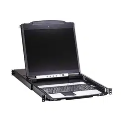
Model:
B064C-16-1X1-IP
NetDirector
®
16-Port Console Cat5
KVM over IP Switch

2
Table of Contents
1. FCC Information 4
2. User Notice 4
3. Package Contents 4
4. Introduction 5
4.1 Overview 5
4.2 Features 5
4.3 Requirements 8
4.3.1 General 8
4.3.2 External Console 8
4.3.3 Computers 8
4.3.4 KVM Adapter Cables 9
4.3.5 Operating Systems 9
4.4 Components 10
4.4.1 Front View 10
4.4.2 Keyboard Module 11
4.4.3 LCD Module 12
4.4.4 Rear View 13
5. Installation 14
5.1 General Safety Instructions 14
5.2 Standard Rack Mounting 16
5.3 Front-L Brackets Mounting 18
5.4 Single-Stage Installation 20
5.5 KVM Adapter Cable Installation 22
5.6 Hot Plugging 23
5.7 Powering Off and Restarting 23
5.8 Port ID Numbering 23
5.9 Port Selection 23
6. KVM Operation 24
6.1 Basic Operation 24
6.1.1 Opening the Console 24
6.1.2 Closing the Console 27
6.2 LCD OSD Configuration 29
6.2.1 LCD Buttons 29
6.2.2 Adjustment Settings 30
6.3 Port Selection 30
7. Administration 31
7.1 IP Address Determination 31
7.1.1 IPv6 32
7.1.2 Trusted Certificates 33
7.1.3 Self-Signed Private Certificates 35
7.2 Super Administrator Setup 36
7.2.1 First-Time Setup 36
7.2.2 Moving On 38
7.3 Logging In 39
7.3.1 Local Console Login 39
7.3.2 Browser Login 40
7.3.3 Windows Client AP Login 40
7.3.4 Java Client AP Login 43
7.4 User Interface 44
7.4.1 Web Browser Main Page 45
7.4.2 AP GUI Main Page 49
7.4.3 Local Console GUI Main Page 50
7.4.4 Control Panel 51
7.5 Port Access 74
7.5.1 Sidebar 75
7.5.2 KVM Devices and Ports – 79
Connections Page
7.5.3 Blade Servers – Connections Page 81
7.5.4 History 84
7.5.5 Favorites 84
7.5.6 Sessions 86
7.5.7 Access 87
7.5.8 Port Configuration 91
7.6 User Management 94
7.6.1 Users 96
7.6.2 Groups 98
7.6.3 Users and Groups 100
7.6.4 Device Assignment 104
7.7 Device Management 106
7.7.1 KVM Devices 106
7.7.2 Blade Servers 126
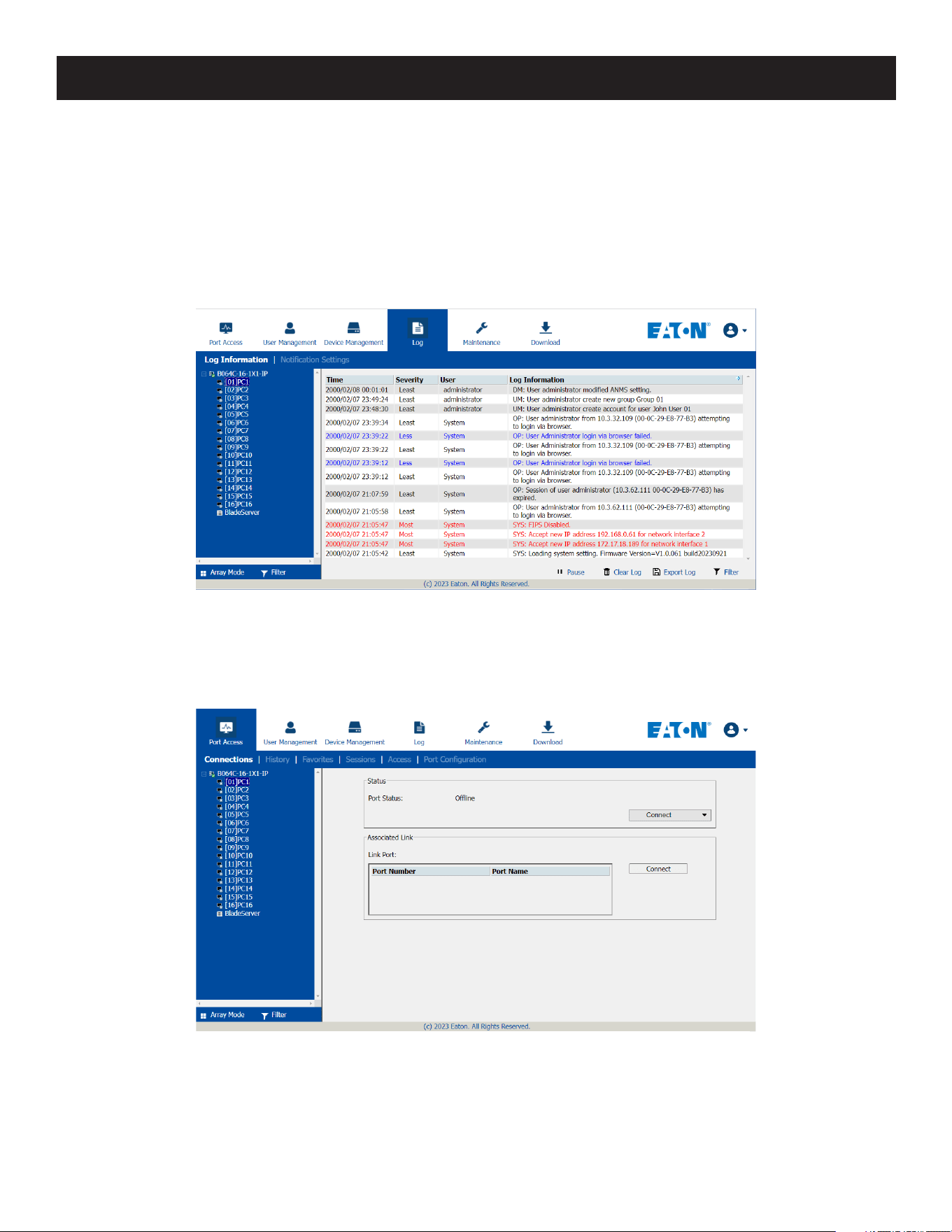
7.8 Log 128
7.8.1 Log Information 129
7.8.2 Log Notification Settings 130

3
Table of Contents
7.9 Maintenance 131
7.9.1 Main Firmware Upgrade 132
7.9.2 Recovering from Failed 132
Firmware Upgrade
7.9.3 Upgrade Adapters 133
7.9.4 Adapter Firmware Upgrade 136
Recovery
7.9.5 Backup/Restore 137
7.9.6 Terminal 138
7.9.7 Restore Values 139
7.10 Download 140
7.11 Port Operation 140
7.11.1 Connecting to a Port 141
7.11.2 Port Toolbar 141
7.11.3 Panel Array Mode 144
7.11.4 Multiuser Operation 145
7.12 Log Server 146
7.12.1 Log Server Installation 146
7.12.2 Log Server Startup 147
7.12.3 Log Server Main Screen 150
8. Troubleshooting 152
8.1 Administration 152
8.2 Operation 152
8.2.1 General Operation 152
8.2.2 Mouse Problems 154
8.2.3 Virtual Media 155
8.2.4 Windows Client 156
8.2.5 Java Client 157
8.2.6 Sun Systems 157
8.2.7 Mac Systems 158
8.2.8 Redhat Systems 158
8.2.9 Log Server 158
8.2.10 Panel Array Mode 159
8.2.11 Screen Resolutions Higher 160
than 1280 x 1024
8.3 Port Forwarding 161
8.4 B055-001-SER Configuration 161
and Operation
8.4.1 Configuration 161
8.4.2 Operation 162
8.4.3 B055-001-SER Pin Assignments 162
8.5 Keyboard Emulation 163
8.5.1 Mac Keyboard 163
8.5.2 Sun Keyboard 164
8.6 Additional Video Resolution Procedures 165
8.6.1 Additional Mouse Synchronization 165
Procedures (Windows, Sun, Linux)
8.7 PPP Modem Operation 168
8.7.1 Basic Setup 168
8.7.2 Connection Setup Example 169
(Windows XP)
8.8 Serial Adapter Pin Assignments 169
8.9 Virtual Media Support 170
8.9.1 WinClient ActiveX Viewer / 170
WinClient AP
8.9.2 Java Client Viewer / Java Client AP 170
8.10 Administrator Login Failure 170
8.11 Factory Default Settings 171
9. Specifications 172
10. Warranty 174

4
1. FCC Information
2. User Notice
3. Package Contents
This is an FCC Class A product. This device complies with part 15 of the FCC Rules. Operation is subject to the following
two conditions: (1) This device may not cause harmful interference, and (2) this device must accept any interference
received, including interference that may cause undesired operation.
Note: This equipment has been tested and found to comply with the limits for a Class A digital device, pursuant to part 15 of the FCC
Rules. These limits are designed to provide reasonable protection against harmful interference when the equipment is operated in a
commercial environment. This equipment generates, uses, and can radiate radio frequency energy and, if not installed and used in
accordance with the instruction manual, may cause harmful interference to radio communications. Operation of this equipment in a
residential area is likely to cause harmful interference in which case the user will be required to correct the interference at his own
expense. The user must use shielded cables and connectors with this equipment. Any changes or modifications to this equipment not
expressly approved by Eaton could void the user’s authority to operate this equipment.
All information, documentation, and specifications contained in this manual are subject to change without prior
notification by the manufacturer. The manufacturer makes no representations or warranties, either expressed or
implied, with respect to the contents hereof and specifically disclaims any warranties as to merchantability or fitness for
any particular purpose. Any of the manufacturer’s software described in this manual is sold or licensed “as is.” Should
the programs prove defective following their purchase, the buyer (and not the manufacturer, its distributor, or its
dealer), assumes the entire cost of all necessary servicing, repair and any incidental or consequential damages resulting
from any defect in the software.
The manufacturer of this system is not responsible for any radio and/or TV interference caused by unauthorized
modifications to this device. It is the responsibility of the user to correct such interference.
The manufacturer is not responsible for any damage incurred in the operation of this system if the correct operational
voltage setting was not selected prior to operation. PLEASE VERIFY THAT THE VOLTAGE SETTING IS CORRECT BEFORE
USE.
This package consists of:
• B064C-16-1X1-IP Console KVM Switch with Built-in IP
• Rack-Mount Hardware (Preinstalled)
• C13 to C14 Power Cord
• User Documentation
Check to make sure that all of the components are present and in good order. If anything is missing, or was damaged
in shipping, contact your dealer.
Read this manual thoroughly and follow the installation and operation procedures carefully to prevent any damage to
the switch or to any other devices on the installation.
5
4. Introduction
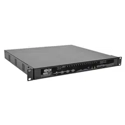
4.1 Overview
The NetDirector Console KVM Switch IP-based KVM control units allow both a local and remote operator to monitor
and access multiple servers from a single KVM (keyboard, video, mouse) console. The B064C-16-1X1-IP can control up
to 16 servers in a single-stage setup.
The B064C-16-1X1-IP features IP-based connectivity that allows one local and one remote operator to concurrently
monitor and access the computers on your installation. Through TCP/IP, the B064C-16-1X1-IP can be accessed from
anywhere via LAN, WAN or Internet — whether it is down the hall, down the street or halfway around the world.
Compact, high-density, RJ45 connectors and CAT 5e/6 cables make for a simple wiring configuration, with the flexibility
to use PS/2 and USB KVM adapter cables in any combination to link various types of computers, including PCs, Macs,
Sun computers and serial devices.
For added convenience, ports for an external keyboard, monitor (DVI-D or VGA), and mouse are provided on the rear
panel, allowing you to manage the switch from a local console.
System administrators can handle a multitude of tasks smoothly and efficiently remotely — from installing and running
GUI applications, to BIOS-level troubleshooting, routine monitoring, concurrent maintenance, system administration,
rebooting and even pre-booting functions.
4.2 Features
Hardware
• Monitor and control up to 16 computers on a single level.
• High video resolution — up to 1920 x 1200 @ 60 Hz with 24-bit color depth at the local console for a distance of up
to 164 ft. (50 m) from the computers and up to 1920 x 1200 @ 60 Hz with 24-bit color depth for remote sessions and
on the external local console.
• One bus for remote KVM over IP access.
• Space-saving RJ45 connectors and Cat 5e/6 cabling.
• KVM adapter cables to allow flexible interface combinations (PS/2, USB, Sun and serial).
• Extra console port — manage computers with the LCD KVM switch from an external console (DVI-D or VGA monitor,
USB keyboard and mouse).
Internet
B064C-16-1X1-IP
Remote
Computer
Local Console
(DVI-D or VGA)

6
4. Introduction
• Multiplatform support: PC, Mac, Sun and serial.
• Supports an external USB mouse.
• Dual-rail housing is slightly less than 1U with top and bottom clearance for smooth operation in a 1U rack space.
• Dual rail — LCD monitor slides independent of the keyboard / touchpad.
Management
• Supports 64 user accounts and up to 32 users can be logged in at the same time for control and management.
• End session feature — administrators can terminate any running session.
• Adapter ID stores port information allowing administrators to relocate servers to different ports without having to
reconfigure the adapters and switch.
• Critical system event notification via SMTP email, SNMP trap and Syslog support.
• Port Share Mode allows multiple users to gain access to a server simultaneously
• Customizable event notification.
• Out-of-Band Access-Modem dial-in/dial out/dial back support.
• Event logging and Windows-based Log Server support.
• Manage browser access (Browser, http, https).
• Local Log Event.
• Firmware upgradeable.
• IPv6 capable.
Easy-to-Use Interface
• Easy computer selection via pushbuttons, Hotkey Mode, OSD (On-Screen Display) and Browser-based GUI.
• Local Console, Browser and AP GUIs offer a unified multi language interface to minimize user training time and
increase productivity
• Multiplatform client support (Windows, Mac OS X, Linux, Sun).
• Multi-browser support: Internet Explorer, Chrome, Firefox, Safari, Opera, Netscape.
• Launch multiple Virtual Remote Desktops to control multiple servers from the same login session Magic Panel.
• Full-screen or sizable and scalable Virtual Remote Desktop.
• Browser-based UI in pure Web technology allows administrators to perform administrative tasks without the need for
Java to be pre-installed.
• Panel Array Mode available to both local console and remote access users.
• Video syncing with the local console — local console monitor’s EDID information is stored on the KVM adapter cables
for display resolution optimization.
• Keyboard/Mouse Broadcast — keyboard and mouse inputs can be duplicated on all the attached servers.
• Keyboard Language support: English (US); English (UK); German; German (Swiss); French; Spanish; Traditional Chinese;
Japanese; Korean; Swedish; Italian; Russian; Hungarian and Greek.

7
4. Introduction
Advanced Security
• Remote authentication support: RADIUS, LDAP, LDAPS and MS Active Directory.
• Supports TLS 1.2 encryption and RSA 2048-bit certificates to secure user logins from browsers.
• Flexible encryption design allows users to choose any combination of 56-bit DES, 168-bit 3DES, 256-bit AES, 128-bit
RC4 or Random for independent KB/Mouse, video and virtual media data encryption.
• IP/MAC Filter support for enhanced security.
• Configurable user and group permissions for server access and control.
• Automated CSR creation utility and third-party CA certificate authentication.
Virtual Media
• Virtual media enables remote file transfers, OS patching software installations and diagnostic testing.
• Works with USB enabled servers at the operating system and BIOS level.
• Supports DVD/CD drives, USB mass storage devices, PC hard drives and ISO images.
• Supports smart card readers on connected computers.
Virtual Remote Desktop
• Video quality can be adjusted to optimize data transfer speed. Monochrome color depth setting, threshold and noise
settings for compression of the data bandwidth in low bandwidth situations.
• High-performance graphics for optimum image quality.
• Full-screen or sizable and scalable Virtual Remote Desktop.
• Message board feature allows logged in users to communicate.
• Mouse DynaSync automatically synchronizes local and remote mouse movements.
• Exit Macros support.
• On-screen keyboard with multilanguage support.
• BIOS-level access.
V-Series Exclusive
• Advanced FPGA graphics processor for improved video quality.
• Faster transmission speed (2x) for virtual media devices.
• A separate bus for remote KVM over IP access.
• Supports FIPS 140-2 level 1 security standards.

8
4. Introduction
4.3 Requirements
4.3.1 General
• Computers with at least a Pentium 4 2+ GHz processor and 1 GB RAM.
• Browsers must support TLS 1.2 encryption.
• Network transfer speed of at least 512 kbps is recommended.
• For the Log Server, Microsoft Jet OLEDB 4.0 or higher driver installed.
4.3.2 External Console
• DVI-D, VGA, SVGA, or Multisync monitor capable of the highest resolution that you will be using on any computer in
the installation.
• USB mouse.
• USB keyboard.
4.3.3 Computers
• VGA, SVGA or Multisync port.
• USB-A port and USB host controller.
• For the browser-based WinClient ActiveX Viewer, DirectX 8 must be present, and at least 150 MB of memory must be
available after installation.
• For the browser-based Java Client Viewer, the latest version of the Java Runtime Environment (JRE) must be installed
and at least 205 MB of memory must be available after installation.
• For the Windows Client AP, DirectX 8 must be present and at least 90 MB of memory must be available after
installation.
• For the Java Client AP, the latest version of the Java Runtime Environment (JRE) must be installed and at least 145 MB
of memory must be available after installation.
• For the Log Server, you must have Microsoft Jet OLEDB 4.0 or later.
Note: The integrated LCD monitor’s maximum screen resolution is 1280 x 1024 @ 75 Hz. If you want to use a higher setting for the screen
resolutions of the attached computers, see 8.2.11 Screen Resolutions Higher than 1280 x 1024.

9
4. Introduction
4.3.4 KVM Adapter Cables
• Cat 5e/6 cable is required to connect the B064C-16-1X1-IP to one of the KVM adapters.
• The following KVM adapters are required for use with the B064C-16-1X1-IP:
Function Model
Connect to devices with PS/2 ports B055-001-PS2
Connect to devices with USB ports (All platforms – PC, Mac, Sun) B055-001-USB
Connect to serial-based devices B055-001-SER
For USB computers – DVI output, Virtual Media and Smart Card Reader support B055-001-UDV
For USB computers – HDMI output, Virtual Media and Smart Card Reader support B055-001-UHD
For USB computers – DisplayPort output, Virtual Media and Smart Card Reader support B055-001-UDP
For USB computers – VGA output, Virtual Media support B055-001-USB-V2
For USB computers – VGA output, Virtual Media and audio support B055-001-USB-VA
For USB computers – VGA output, Virtual Media and Smart Card Reader support B055-001-UV2CAC
Connect to devices with USB-C port, with virtual media support B055-001-C
Note: If you use KVM adapters purchased prior to your switch purchase, you may need to upgrade the adapter’s firmware.
4.3.5 Operating Systems
• Supported operating systems for remote user computers include Windows 2000 or later and those capable of
running the Java Runtime Environment (JRE) 6, Update 3 or higher (Linux, Mac, Sun, etc.).
• Supported operating systems for the servers connected to the switch’s ports are shown in the table below:
OS Version
Windows XP or later
Linux RedHat 7.1 or later
Fedora Core 2 or later
SuSE 9.0 or later
Mandriva (Mandrake) 9.0 or later
UNIX AIX 4.3 or later
FreeBSD 4.2 or later
Sun Solaris 8 or later
Novell Netware 5.0 or later
Mac OS 9 or later
DOS 6.2 or later
10
4. Introduction
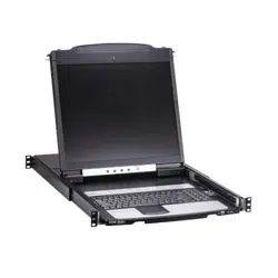
4.4 Components
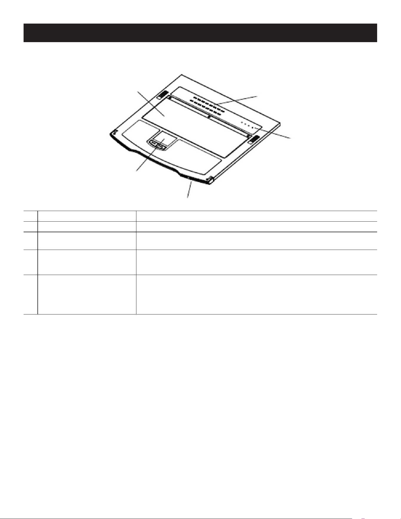
4.4.1 Front View
1
Upper Handle
Pull to slide the LCD module out; push to slide the module in. See 6.1.1
Opening the Console for more information.
2
LCD Module Refer to 4.4.3 LCD Module, for a detailed description.
3
Keyboard Module Refer to 4.4.2 Keyboard Module, for a detailed description.
4
Lower Handle
Pull to slide the keyboard module out. See 6.1.1 Opening the Console for
more information.
5
Power LED Illuminates (blue) to indicate the unit is receiving power.
6
Keyboard Release Catch These (one on each side) release the keyboard module to slide it out.
7
LCD Release Catch These (one on each side) release the LCD module to slide it out.
8
Rack-Mount Brackets
The rack mount brackets located at each corner of the unit secure the chassis to
a system rack. See 5.2 Standard Rack Mounting for more information.
11
22
33
44
55
66
77
88
11
4. Introduction
4.4.2 Keyboard Module
1
Keyboard Standard 105-key QWERTY keyboard.
2
Touchpad Standard mouse touchpad.
3
External Mouse Port
A USB Type-A mouse port is provided for users who prefer to use an external
mouse.
4
Lock LEDs and Reset Button
The Num Lock, Caps Lock, Scroll Lock LEDs are located here.
A reset button is located just to the right of the Lock LEDs. Press this button
using a thin object to perform a system reset.
5
Port Selection Buttons and
LEDs
To access a port on the currently selected station, press its corresponding port
selection button. Indicator LEDs are built into the switches:
• An On-Line LED illuminates to indicate the computer attached to its corre-
sponding port is up and running.
• A Selected LED illuminates to indicate which port has the KVM focus.
11
22
33
44
55
12
4. Introduction
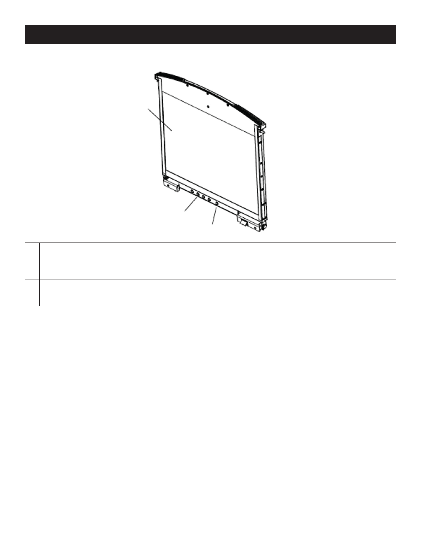
4.4.3 LCD Module
1
LCD Display
To access the LCD monitor, slide the LCD module out and ip up the cover. See
6.1.1 Opening the Console for more information.
2
LCD Controls
These buttons control the position and picture settings of the LCD display. See
6.2 LCD OSD Conguration for more information.
3
LCD On / O Button
Push this button to turn the LCD monitor on and o. The button illuminates
when the LCD monitor is o to indicate that only the monitor is o and not the
KVM switch itself.
11
22
33
13
4. Introduction
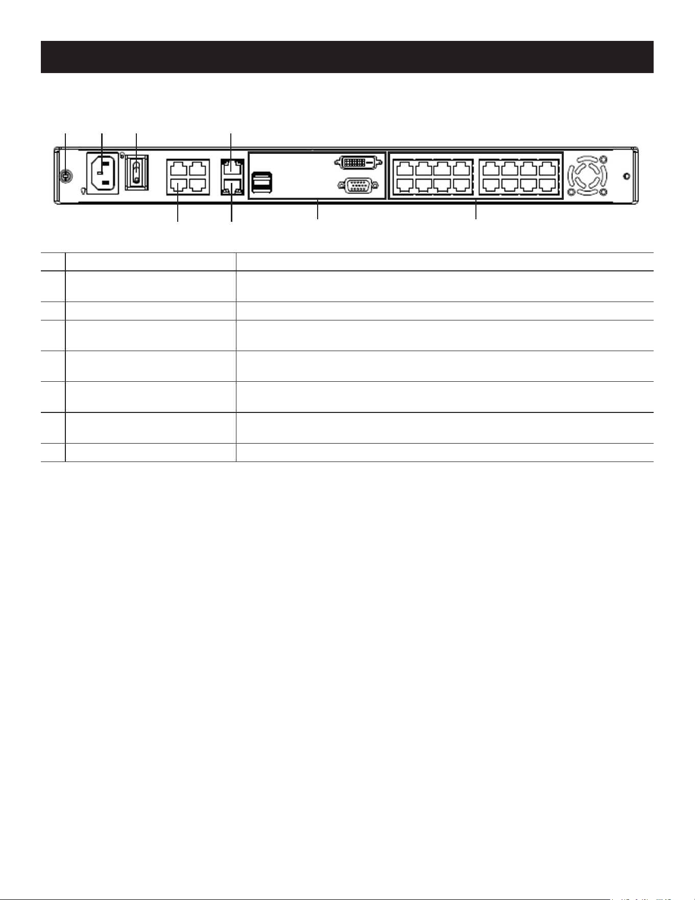
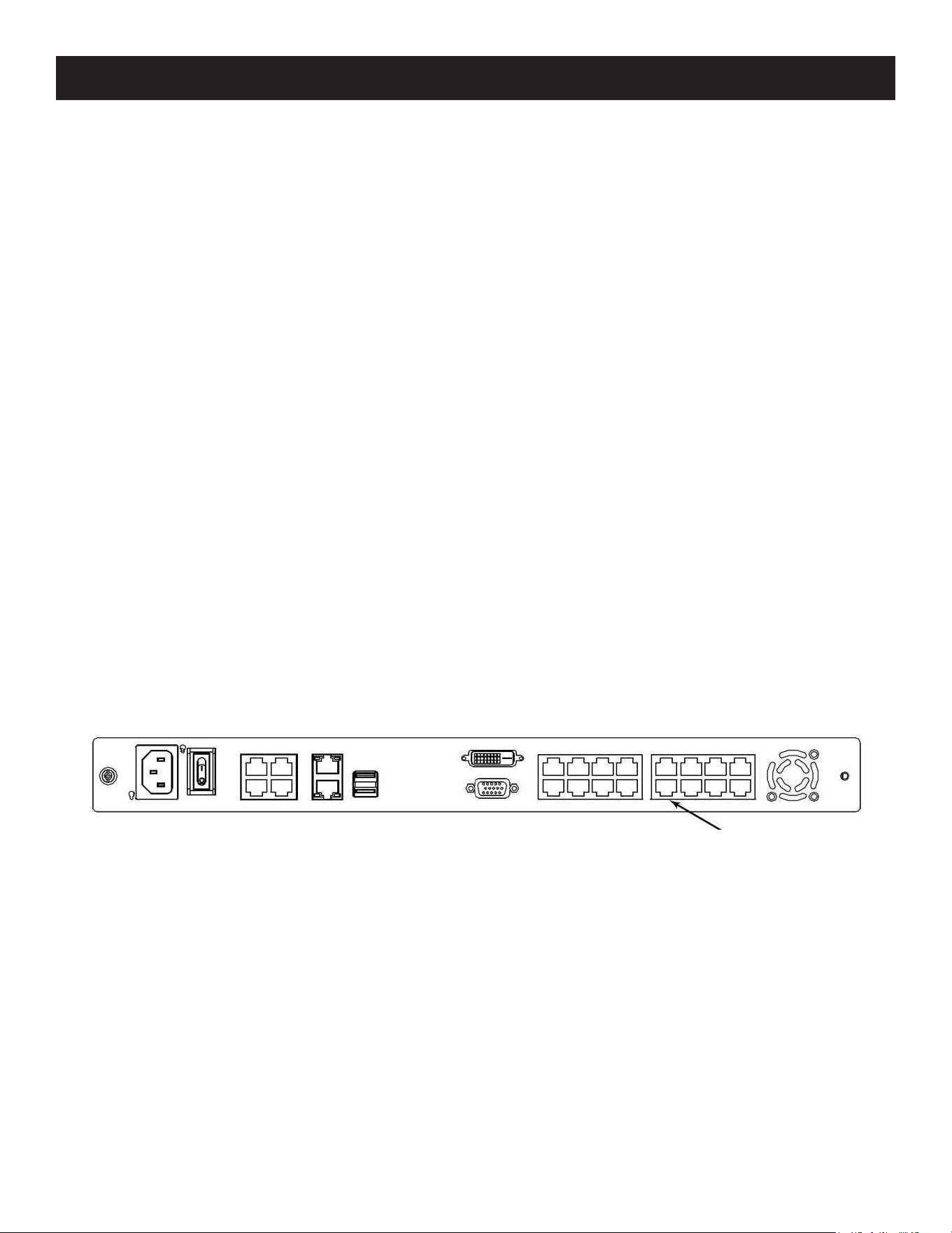
4.4.4 Rear View
1
Grounding Terminal The grounding wire used to ground the switch attaches here.
2
Power Socket
This is a standard C14 AC power socket. The power cord from an AC source
plugs in here.
3
Power Switch This is a standard rocker switch that powers the unit on and o.
4
LAN 2 Port
The cable that connects the unit to the backup network interface (10/100/1000
Mbps) plugs in here.
5
Modem Port
For a dial-in connection in the event the unit is unavailable over the network
(see 6.4 Single-Stage Installation for details).
6
LAN 1 Port
The cable that connects the unit to the primary network interface (10/100/1000
Mbps) plugs in here.
7
Local Console Port Section
If this is a single-station installation or you would like to connect an external con-
sole, the keyboard, monitor and mouse for the local console plug in here.
8
KVM Port Section The Cat 5e/6 cables that link to the KVM adapter cables plug in here.
11 22 33 44
55 66 77 88

14
5. Installation
5.1 General Safety Instructions
• Read all of these instructions. Save them for future reference.
• Follow all warnings and instructions marked on the device.
• This product is for indoor use only.
• Do not place the device on any unstable surface (cart, stand, table, etc.). If the device falls, serious damage will result.
• Do not use the device near water.
• Do not place the device near or over radiators or heat registers.
• The device cabinet is provided with slots and openings to allow for adequate ventilation. To ensure reliable operation
and to protect against overheating, these openings must never be blocked or covered.
• The device should never be placed on a soft surface (bed, sofa, rug, etc.) as this will block its ventilation openings.
Likewise, the device should not be placed in a built-in enclosure unless adequate ventilation has been provided.
• Never spill liquid of any kind on the device.
• Unplug the device from the wall outlet before cleaning. Do not use liquid or aerosol cleaners. Use a damp cloth for
cleaning.
• The device should be operated from the type of power source indicated on the marking label. If you are not sure of
the type of power available, consult your dealer or local power utility.
• The device is designed for IT power distribution systems with 230V phase-to-phase voltage.
• To prevent damage to your installation, it is important that all devices are properly grounded.
• The device is equipped with a 3-wire grounding type plug. This is a safety feature. If you are unable to insert the plug
into the outlet, contact your electrician to replace your obsolete outlet. Always follow your local/national wiring codes.
• Do not allow anything to rest on the power cord or cables. Route the power cord and cables so that they cannot be
stepped on or tripped over.
• Avoid circuit overloads. Before connecting equipment to a circuit, know the power supply’s limit and never exceed it.
Always review the electrical specifications of a circuit to ensure that you are not creating a dangerous condition or
that one does not already exist. Circuit overloads can cause a fire and destroy equipment.
• If an extension cord is used with this device make sure that the total of the ampere ratings of all products used on
this cord does not exceed the extension cord ampere rating. Make sure that the total of all products plugged into the
wall outlet does not exceed 15 amperes.
• To help protect your system from sudden, transient increases and decreases in electrical power, use a surge
suppressor, line conditioner or uninterruptible power supply (UPS).
• Position system cables and power cables carefully; be sure nothing rests on any cables.
• Never push objects of any kind into or through cabinet slots. They may touch dangerous voltage points or short out
parts, resulting in a risk of fire or electrical shock.
• Do not attempt to service the device yourself. Refer all servicing to qualified service personnel.
• If the following conditions occur, unplug the device from the wall outlet and bring it to qualified service personnel for
repair:
o The power cord or plug has become damaged or frayed.
o Liquid has been spilled into the device.
o The device has been exposed to rain or water.
o The device has been dropped, or the cabinet has been damaged.
o The device exhibits a distinct change in performance, indicating a need for service.
• The device does not operate normally when the operating instructions are followed.
• Only adjust those controls that are covered in the operating instructions.
• Improper adjustment of other controls may result in damage that will require extensive work by a qualified technician
to repair.
• Do not connect the RJ11 connector marked “UPGRADE” to a public telecommunications network.

15
5. Installation
Rack Mounting Safety Instructions
• Prior to installation, ensure KVM is powered OFF and de-energized.
• Before working on the rack, make sure the stabilizers are secured to the rack, extended to the floor and that the full
weight of the rack rests on the floor. Install front and side stabilizers on a single rack or front stabilizers for joined
multiple racks before working on the rack.
• Always load the rack from the bottom to top; load the heaviest item in the rack first.
• Make sure the rack is level and stable before extending a device from the rack.
• Use caution when pressing the device rail release latches and sliding a device into or out of a rack; the slide rails can
pinch your fingers.
• After a device is inserted into the rack, carefully extend the rail into a locking position, then slide the device into the
rack.
• Do not overload the AC supply branch circuit that provides power to the rack. The total rack load should not exceed
80 percent of the branch circuit rating.
• Make sure that all equipment used on the rack - including power strips and other electrical connectors - are properly
grounded.
• Ensure that proper airflow is provided to devices in the rack.
• Ensure that the operating ambient temperature of the rack environment does not exceed the maximum ambient
temperature specified for the equipment by the manufacturer.
• Do not step on or stand on any device when servicing other devices in a rack.
• Caution: Slide/rail (LCD KVM) mounted equipment is not to be used as a shelf or a workspace.
16
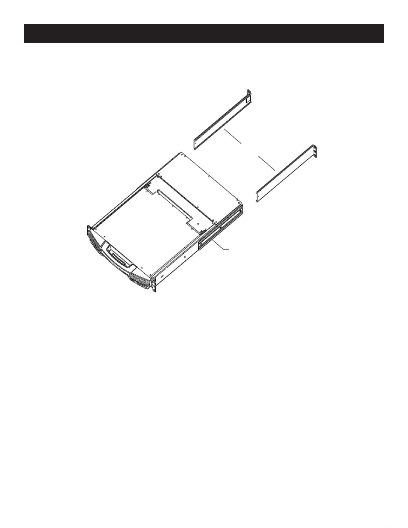
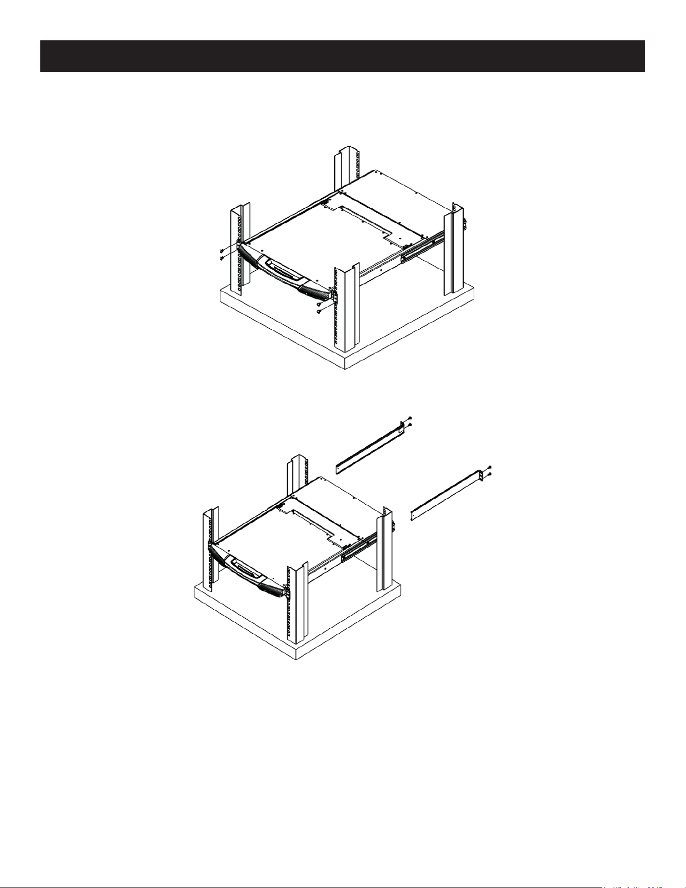
5.2 Standard Rack Mounting
A standard rack mount kit is provided with your B064C-16-1X1-IP. The kit enables the switch to be mounted in a rack
with a depth of 15.5-30 in. (40-77 cm).
Notes:
• Two people are required to mount the console.
• The standard rack-mount kit does not include screws or cage nuts.
• If you need additional screws or cage nuts, contact your rack dealer.
5. Installation
Side Mount Bracket
Left and Right L-Brackets
17
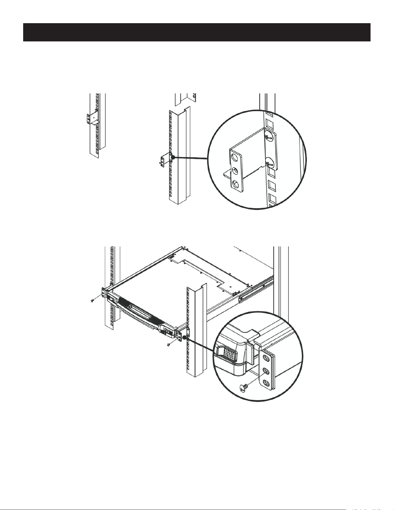
5. Installation
To rack mount the switch:
1. Have one person position the unit in the rack and hold it steady, then the second person attaches the front brackets
to the rack.
2. While the first person continues to hold the unit in place, the second person slides the left and right L-brackets into
the unit’s side mount brackets from the rear. Secure the brackets in place using the four screws.
3. Once the L-brackets are secured, tighten all the screws.
Allow at least 2 in. (5.1 cm) on each side for proper ventilation, and at least 5 in. (12.7 cm) at the back for power cord
and cable clearance.
18
5. Installation
5.3 Front-L Brackets Mounting
To better enable the tilt function of the LCD screen, install the front L-brackets at the front of the rack.
1. To attach the left and right front L-brackets to the front of the rack, first place screws in the tabs to secure them in
place.
Note: Rack screws are not provided to mount the unit. We recommend using M5 x P0.8 screws.
2. Have one person position the unit in the rack and hold it steady. Then have the second person screw the front
brackets to the front L-bracket.
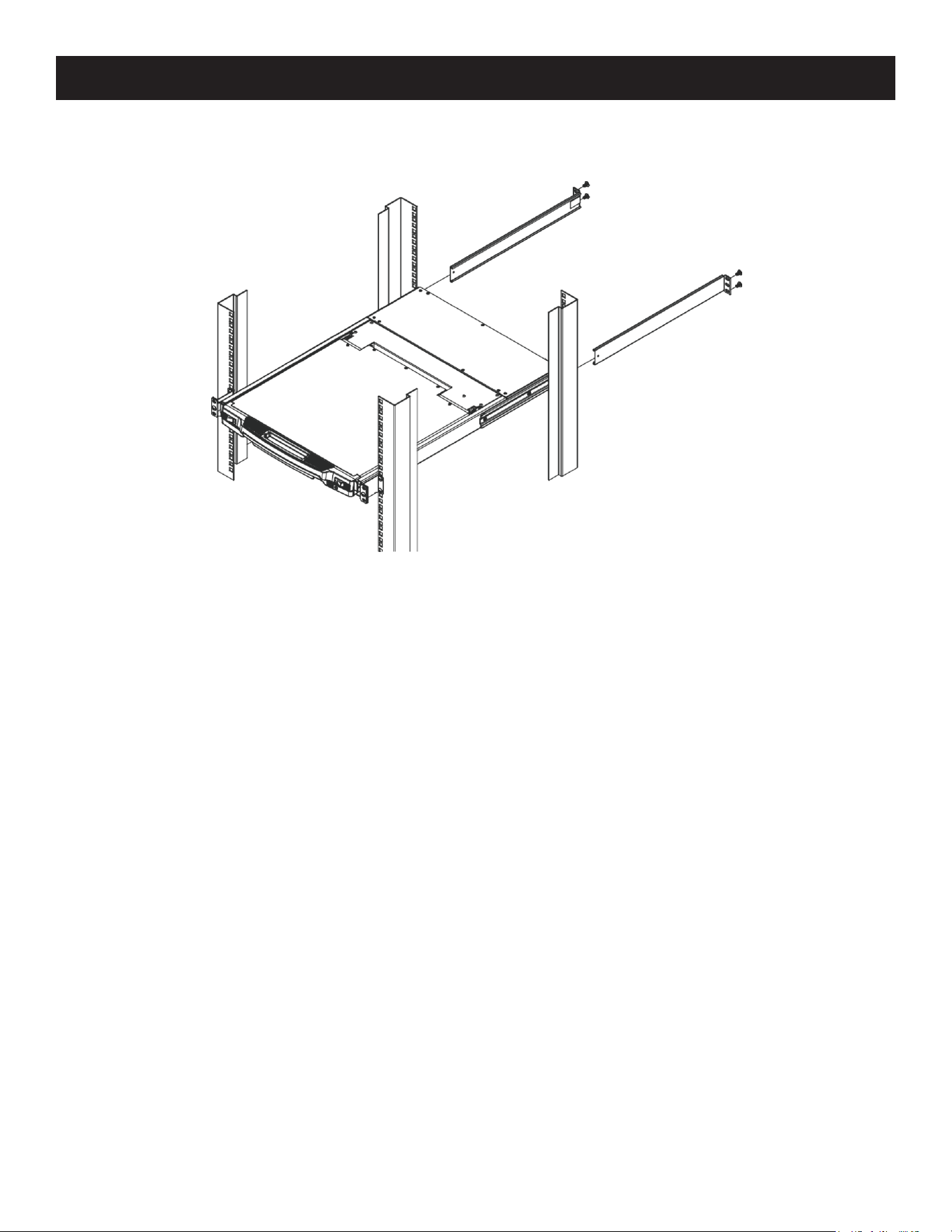
19
5. Installation
3. While the first person continues to hold the unit in place, the second person slides the left and right L-Brackets into
the unit’s side mount brackets from the rear. Secure the bracket using four screws.
4. Once the L-brackets are secured, tighten all screws.
Allow at least 2 in. (5.1 cm) on each side for proper ventilation, and at least 5 in. (12.7 cm) at the back for power cord
and cable clearance.
20
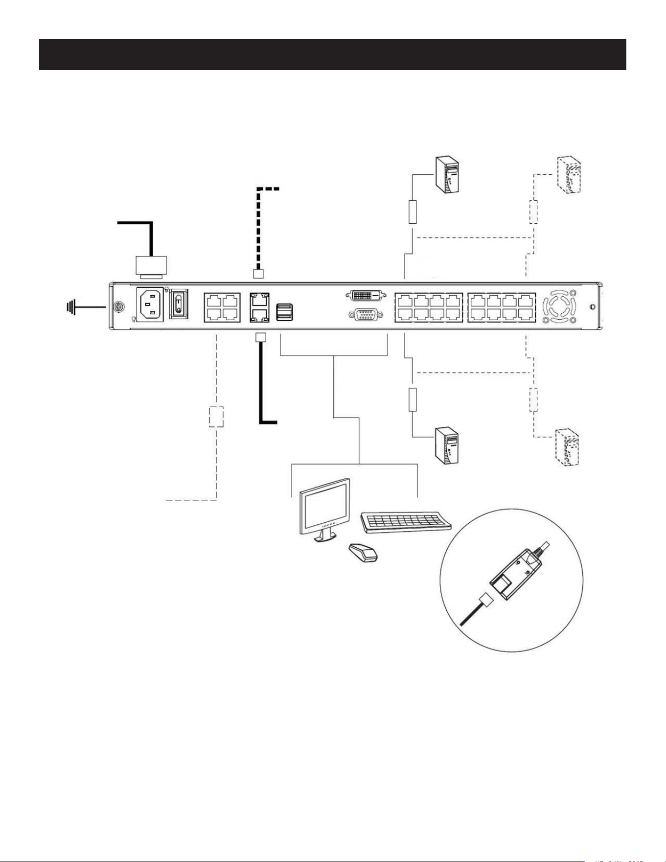
5.4 Single-Stage Installation
In a single-stage installation, there are no additional switches daisy-chained down from the first unit. To set up your
console KVM switch, refer to the following steps and installation diagram.
5. Installation
11
22
88
77
55
66
44
33
33
Modem

21
5. Installation
1
Ground the unit by connecting one end of a grounding wire to the grounding terminal and the other end of the
wire to a suitable grounded object.
Note: Do not omit this step. Proper grounding helps to prevent damage to the unit from power surges or static electricity.
2
(Optional) If you choose to install an external console, plug your keyboard, monitor and mouse into the console
ports located on the switch’s rear panel. The ports are color coded and marked with an icon for easy identification.
3
For each computer you are installing, use Cat5e cable to connect any available KVM port to a KVM adapter cable
that is appropriate for the computer you are installing (see 4.3.4 KVM Adapter Cables for details).
Note: The maximum supported distance to the adapter cable is 164 ft. (50 m).
4
Connect the KVM Adapter cable to the computer. Refer to the KVM Adapter Cable lnstallation Diagram to plug the
adapter cable connectors into their respective ports on the computers you are installing.
5
Plug the LAN or WAN cable into the B064C-16-1X1-IP’s LAN port.
6
(Optional) Plug another cable from the LAN into the B064C-16-1X1-IP’s LAN 2 port.
7
(Optional) Use Cat 5e cable to connect the modem port to an RJ45 to DB9 adapter for dial-in modem functionality.
8
Connect the power cord to the switch and to an AC power source.
Once the B064C-16-1X1-IP is connected properly, you can turn on the power. After the switch is powered on, then turn
on the servers.
22
5. Installation
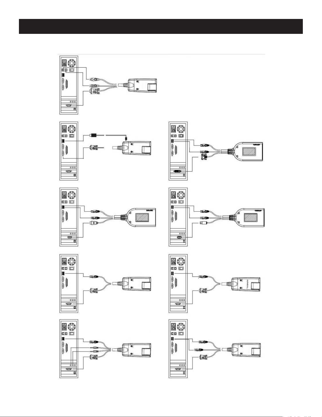
5.5 KVM Adapter Cable Installation
B055-001-PS2
B055-001-SER
B055-001-UDV
B055-001-UHD
B055-001-UDP
B055-001-USB B055-001-USB-V2
B055-001-USB-VA B055-001-UV2CAC
23
5. Installation
5.6 Hot Plugging
Dual-Rail LCD Over-IP KVM Switches support hot plugging in which components can be removed and added back into
the installation by unplugging and replugging cables from the ports without needing to shut the unit down.
Note: If the server’s operating system does not support hot plugging, this function may not work properly.
The Adapter ID Function
Adapter cable information (the adapter ID, port name, OS, keyboard language, and access mode) is stored on the
adapter. The switch’s Adapter ID function takes this information and stores it along with the adapter cable’s
configuration information (access rights, etc.) in its database so when you move a server together with its adapter cable
from one port to another, you do not have to reconfigure its settings as the Adapter ID function restores them at the
new location. The only change is in the port number.
When moving the server and adapter cable to another switch, however, only the information that is stored on the
adapter is retained. For the other settings, you must either reconfigure them or use the Backup/Restore function to
restore them.
Since port settings are stored with the adapter, if you move a server to a new port without its original adapter or if you
connect a different server to the adapter, you must manually reconfigure the port settings for the new server.
5.7 Powering Off and Restarting
If it becomes necessary to power off the switch or if the switch loses power and needs to be restarted, wait 30 seconds
before powering it back on. The servers should not be affected by this, but if any of them should fail simply restart
them.
5.8 Port ID Numbering
Each server on the installation is assigned a unique Port ID. Its Port ID is a one or two segment number that is
determined as:
• A server attached to a First Stage unit has a one segment Port ID (from 1–16) that corresponds to the KVM Port
number that it is connected to.
For example, a Port ID of 5 - 3 refers to a server that is connected to KVM Port 3 of a Second Stage unit that links back
to KVM Port 5 of the First Stage unit:
5.9 Port Selection
Port selection is accomplished by means of the GUI. Port selection details are discussed in 7.5 Port Access.
Port 05
24
6. KVM Operation
6.1 Basic Operation
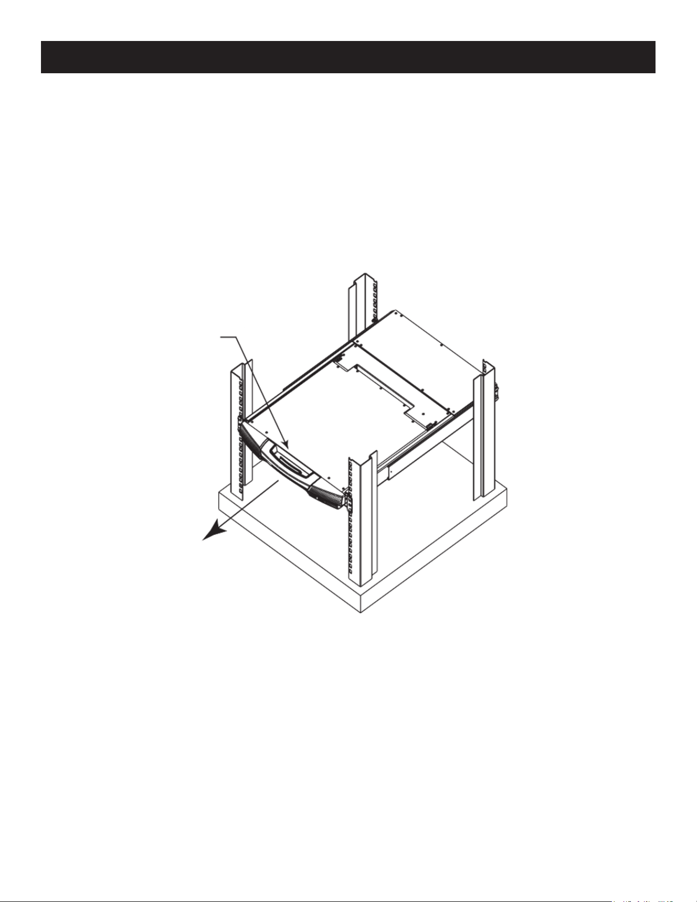
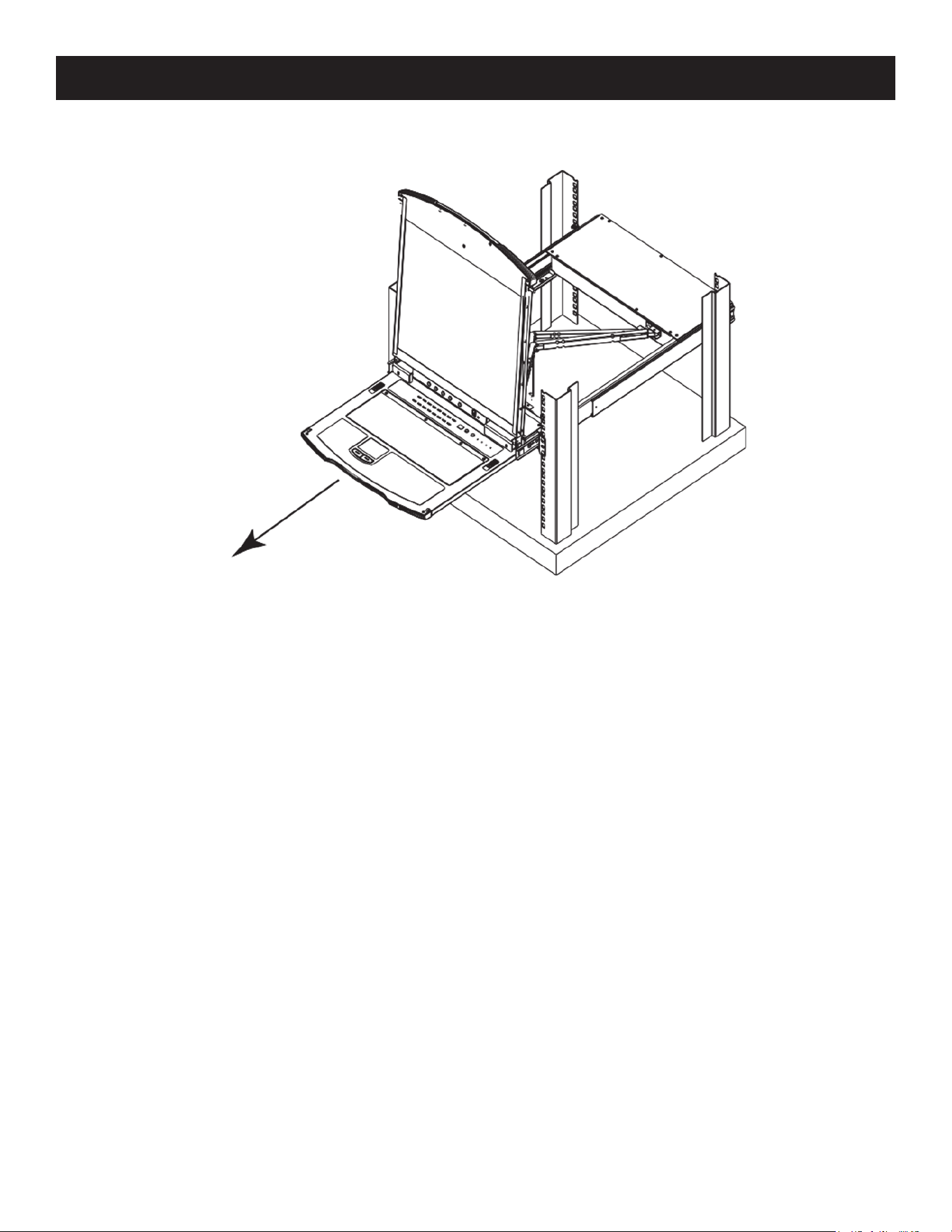
6.1.1 Opening the Console
The B064C-16-1X1-IP consists of two modules: an LCD display module located under the top cover and a keyboard /
touchpad module below the LCD module.
The modules can slide together or independently. This allows you to have the LCD display available for viewing while
the keyboard / touchpad module is conveniently out of the way when not in use.
Opening Separately
1. Pull the release catch to disengage the console and pull the top panel slightly toward you. Once the console has
been released, let go of the release catch.
Release catch
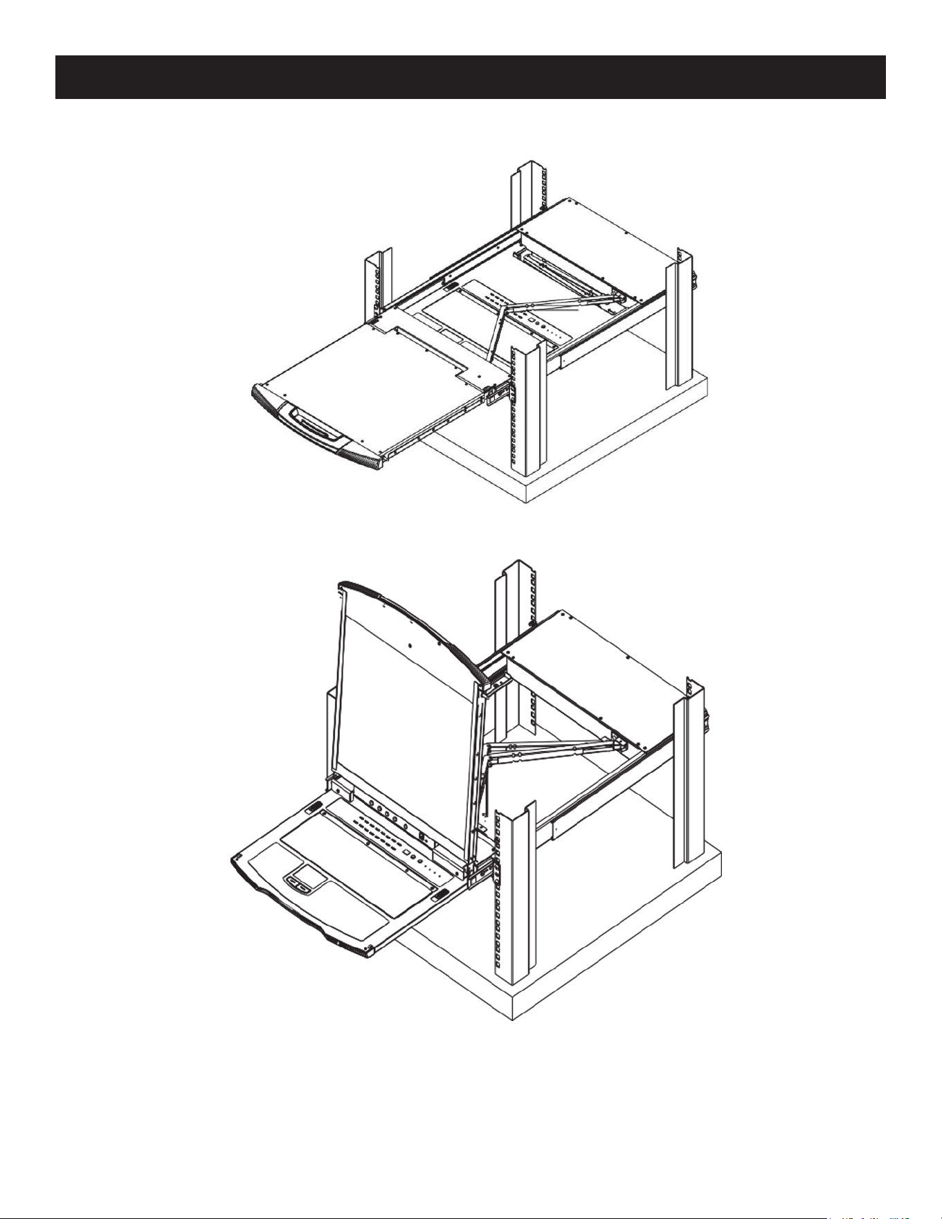
25
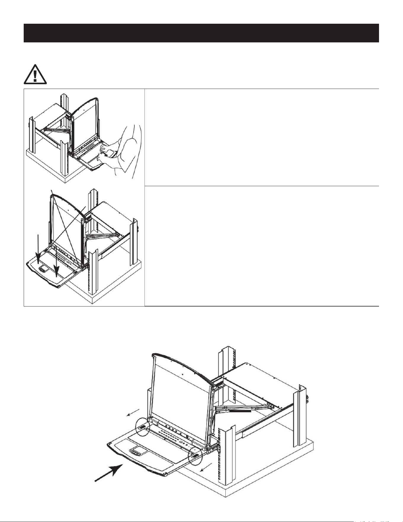
6. KVM Operation
2. Pull out the top panel completely until it clicks into place.
3. Rotate the top panel backward to expose the LCD screen.
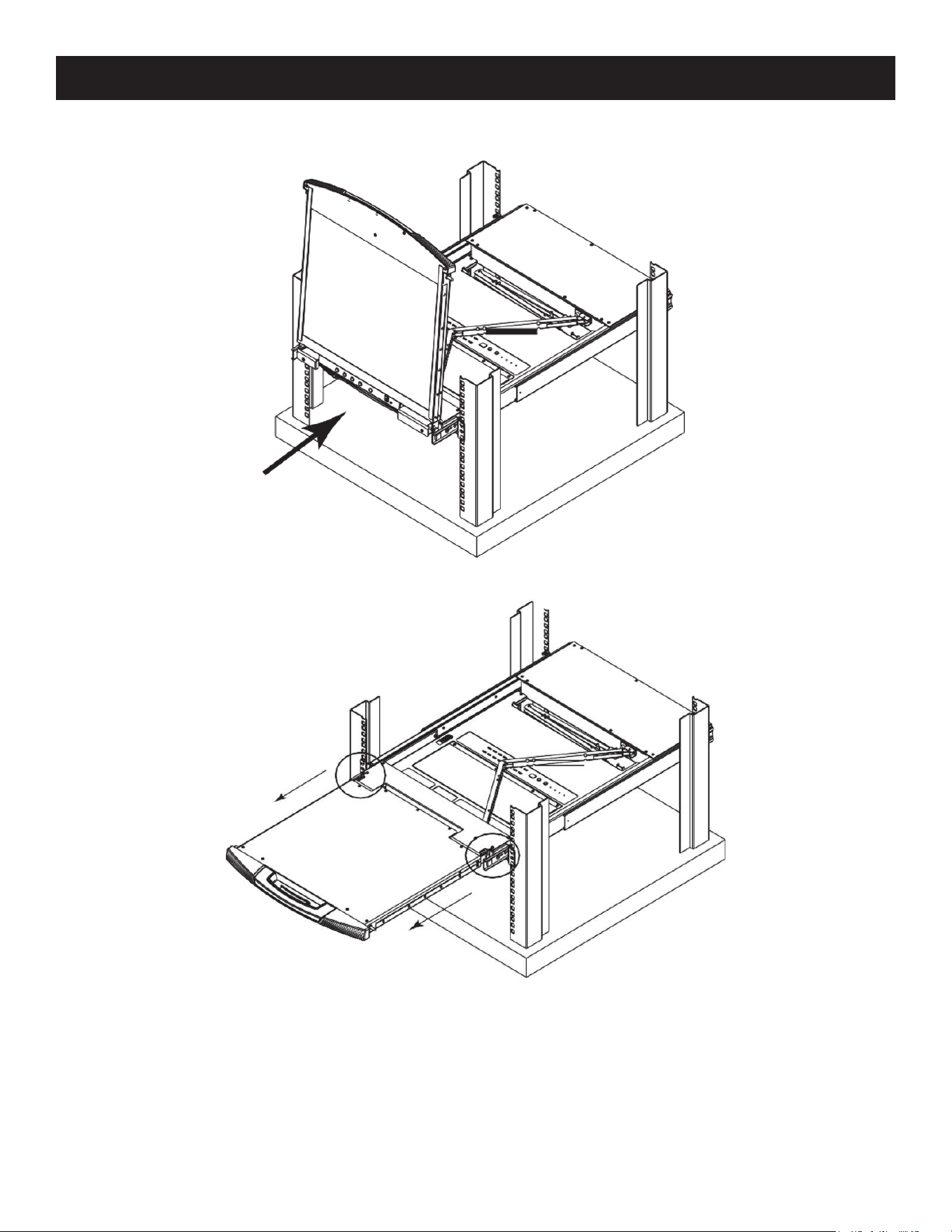
26
6. KVM Operation
4. Reach underneath and pull out the keyboard module completely until it clicks into place.
Opening Together
Refer to the diagrams in the Opening Separately section as you do the following:
1. While holding the release catch, pull the top and bottom panels out until the keyboard module clicks into place.
Note: Once the console has been released, release the release catch.
2. Pull out the top panel the rest of the way out until it clicks into place.
3. Rotate the top panel backward to expose the LCD screen.
27
6. KVM Operation
Operating Precautions
The maximum load bearing capacity of the keyboard module is 44 lb. (20 kg). Failure to heed the following
information may result in damage to the keyboard module:
Correct
Rest your hands and arms lightly on the keyboard module as you work.
Incorrect
• DO NOT lean your body weight on the keyboard module.
• DO NOT place heavy objects on the keyboard module.
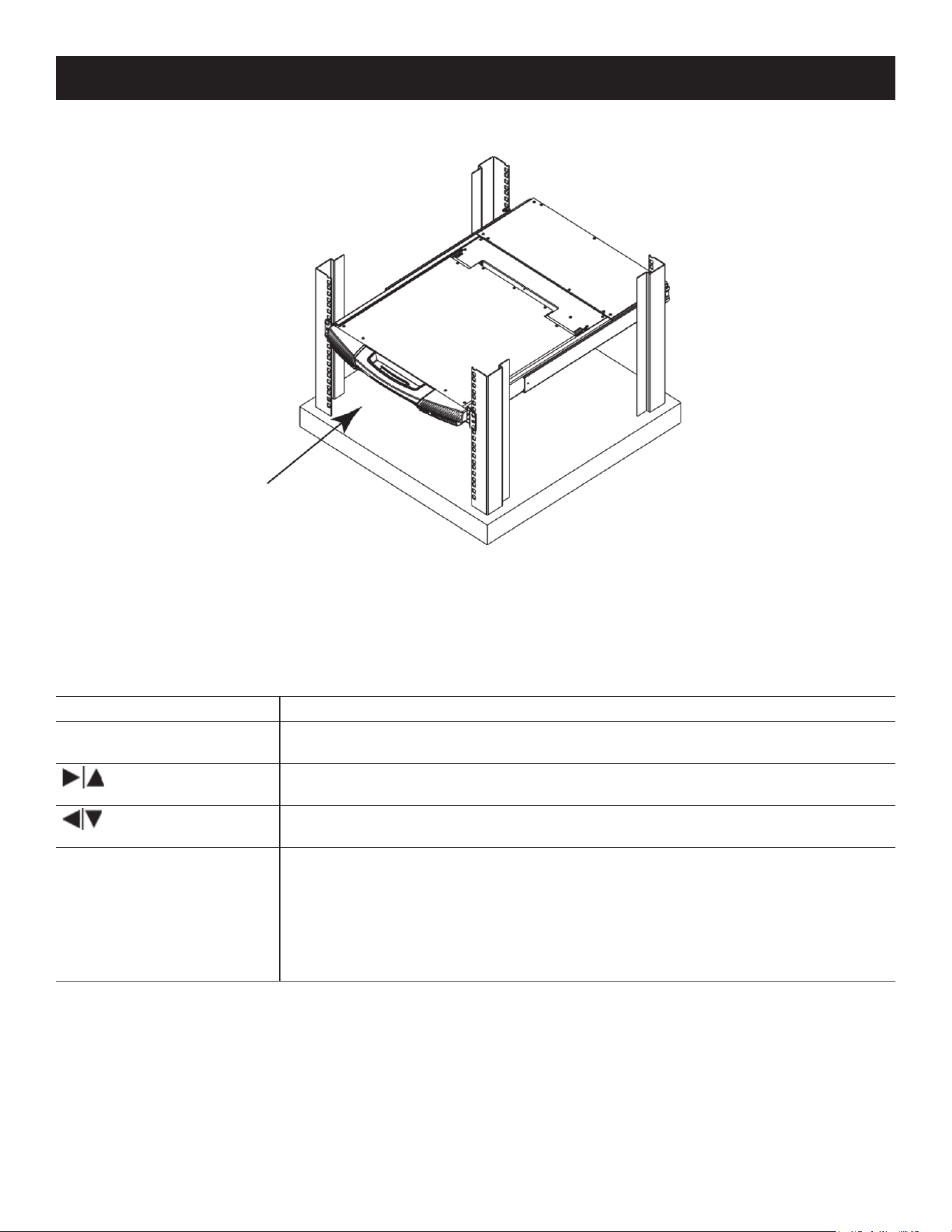
6.1.2 Closing the Console
1. Pull the release catches located on each side of the keyboard toward you to release the keyboard module, then slide
in the module slightly.
28
2. Release the release catches. Using the front handle, push in the keyboard module completely.
3. Rotate the LCD module completely, then pull the rear release catches to release the LCD module.
6. KVM Operation
29
6. KVM Operation
4. Using the front handle, push in the module completely.
6.2 LCD OSD Configuration
6.2.1 LCD Buttons
The LCD OSD allows you to set up and configure the LCD display. Four buttons are used to perform the configuration,
as described in the table below:
Button Function
MENU When you have not entered the LCD OSD Menu function, pressing this button invokes
the Menu function and opens the Main Menu.
When navigating through the menus, this button moves you right or up. When making
an adjustment, it increases the value.
When navigating through the menus, this button moves you left or down. When mak-
ing an adjustment, it decreases the value.
EXIT • When you have not entered the LCD OSD Menu function, pressing this button per-
forms an auto adjustment. An auto adjustment automatically congures all settings
for the LCD panel to what the OSD considers their optimum values to be.
• When you have entered the LCD OSD Menu function, pressing this button exits the
current menu and returns you to the previous menu. Use it to leave an adjustment
menu when you are satised with the adjustment you have made.
• When you are at the Main Menu, pressing this button exits the LCD OSD.

30
6. KVM Operation
6.2.2 Adjustment Settings
An explanation of the LCD OSD adjustment settings is provided in the table below:
Setting Explanation
Auto Adjust Auto adjust screen image and resolution
OSD Adjust OSD Positions and OSD Display Time
Luminance Adjusts brightness and contrast level of the screen image.
Language Selects the language that the OSD displays its menus in.
Geometry Positions the display area on the LCD panel. Adjust Pixel Clock and Phase.
Recall Color Recall and Recall All Settings (factory defaults)
Color Adjusts the color quality of the display between three pre-congured settings; 5800k,
6500k, 9300k. This menu also allows you to customize the individual RGB settings to
your preference.
Miscellaneous Adjust Sharpness and Display Information.
Exit
6.3 Port Selection
The B064C-16-1X1-IP provides three methods to obtain instant access to any computer in your installation: Manual, GUI
and Hotkeys.
Manual
For manual port selection, simply press the Port Switch that corresponds to the device you wish to access.
GUI
The B064C-16-1X1-IP provides menu-driven interfaces to the computer switching procedure. A graphical user interface
(GUI) is used when you log in locally and remotely over the Internet.
Hotkeys
Hotkeys allow you to conveniently provide KVM focus to a particular computer from the local console keyboard instead
of having to manually select them by pressing Port Selection switches.
31
7. Administration
7.1 IP Address Determination
If you are an administrator logging in for the first time, you need to access the B064C-16-1X1-IP in order to give it an IP
address that users can connect to. There are three methods to choose from. In each case, your client computer must
be on the same network segment as the B064C-16-1X1-IP. After you have connected and logged in you can give the
B064C-16-1X1-IP its fixed network address.
The Local Console
The easiest way to assign an IP address is from the local console.
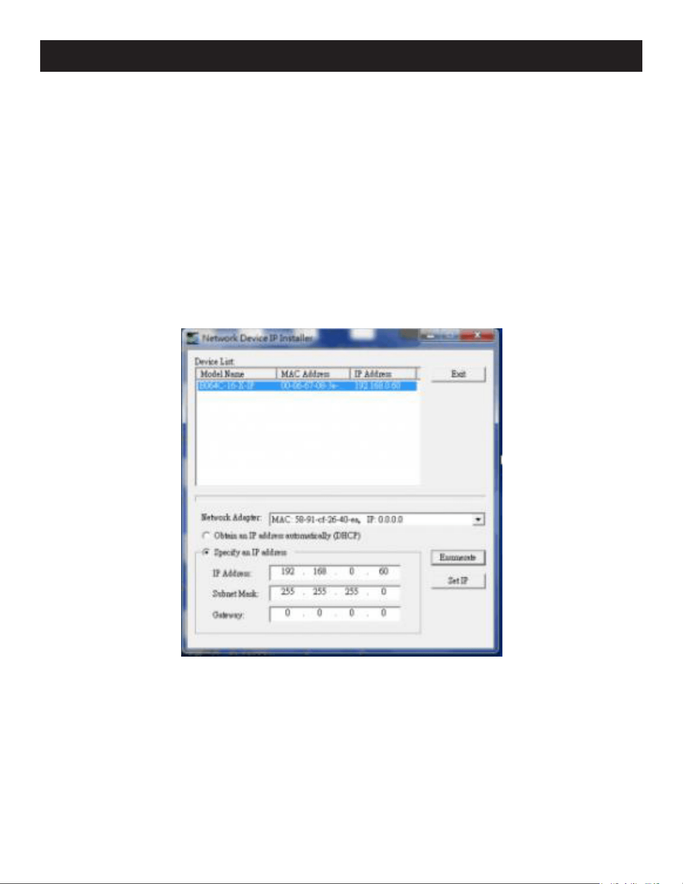
IP Installer
For client computers running Windows, an IP address can be assigned with the IP lnstaller utility. The IP Installer utility
can be obtained from Eaton’s technical support or website. Look under DriverISW, and the model of your switch. After
downloading the utility to your client computer, do the following:
1. Unzip the contents of lPlnstaller.zip to a directory on your hard drive.
2. Go to the directory that you unzipped the IPInstaller program to and run lPlnstaller.exe. A dialog box similar to the
one below will appear:
3. Select B064C-16-1X1-IP in the Device List.
Notes:
• If the list is empty, or your device does not appear, click Enumerate to refresh the Device List.
• If there is more than one device in the list, use the MAC address to pick the one you want.
4. Select Obtain an lP address automatically (DHCP) or Specify an lP address. If you chose the latter, fill the IP Address,
Subnet Mask and Gateway fields with the information appropriate to your network.
5. Click Set IP.
6. After the IP address shows up in the Device List, click Exit.

32
Browser
1. Set your client computer’s IP address to 192.168.0.XXX
Where XXX represents any number or numbers except 60 (192.168.0.60 is the default address of the B064C-16-1X1-
IP).
2. Specify the switch’s default IP address (192.168.0.60) in your browser to connect.
3. Assign a fixed IP address for the B064C-16-1X1-IP that is suitable for the network segment that it resides on.
After you log out, reset your client computer’s IP address to its original value.
7.1.1 IPv6
The B064C-16-1X1-IP supports three IPv6 address protocols: Link Local lPv6 Address, lPv6 Stateless Autoconfiguration
and Stateful Autoconfiguration (DHCPv6).
Link Local IPv6 Address
At power on, the B064C-16-1X1-IP is automatically configured with a Link Local IPv6 Address (for example,
fe80::210:74ff:fe61:1ef). To determine what the Link Local IPv6 Address is, log in with the B064C-16-1X1-IP IPv4 address
and open the Device Management Device Information page. The address is displayed in the General list box.
Once you have determined the IPv6 address, you can use it when logging in from a browser or the Win and Java Client
AP programs.
For example:
If you are logging in from a browser, you would key:
http://[fe80::2001:74ff:fe6e:59%5]
for the URL bar.
If you are logging in with the AP program, you would key:
fe80::2001:74ff:fe6e:59%5
for the IP field of the Server panel (see 7.3.3 Windows Client AP Login).
Notes:
• To log in with the Link Local IPv6 Address, the client computer must be on the same local network segment as the B064C-16-1X1-IP.
• The %5 is the %interface used by the client computer. To see your client computer’s IPv6 address: from the command line issue the
following command: ipconfig /all. The % value appears at the end of the IPv6 address.
IPv6 Stateless Autoconfiguration
If the B064C-16-1X1-IP network environment contains a device (such as a router) that supports the IPv6 Stateless
Autoconfiguration function, the B064C-16-1X1-IP can obtain its prefix information from that device to generate its IPv6
address. For example: 2001::74ff:fe6e:59.
As above, the address is displayed in the General list box of the Device Management Device Information page.
Once you have determined the IPv6 address, you can use it when logging in from a browser or the Win and Java Client
AP programs.
For example:
If you are logging in from a browser, you would key:
http://[2001::74ff:fe6e:59]
for the URL bar.
If you are logging in with the AP program, you would key:
2001::74ff:fe6e:59
for the IP field of the Server panel (see 7.3.3 Windows Client AP Login).
7. Administration
33
7. Administration
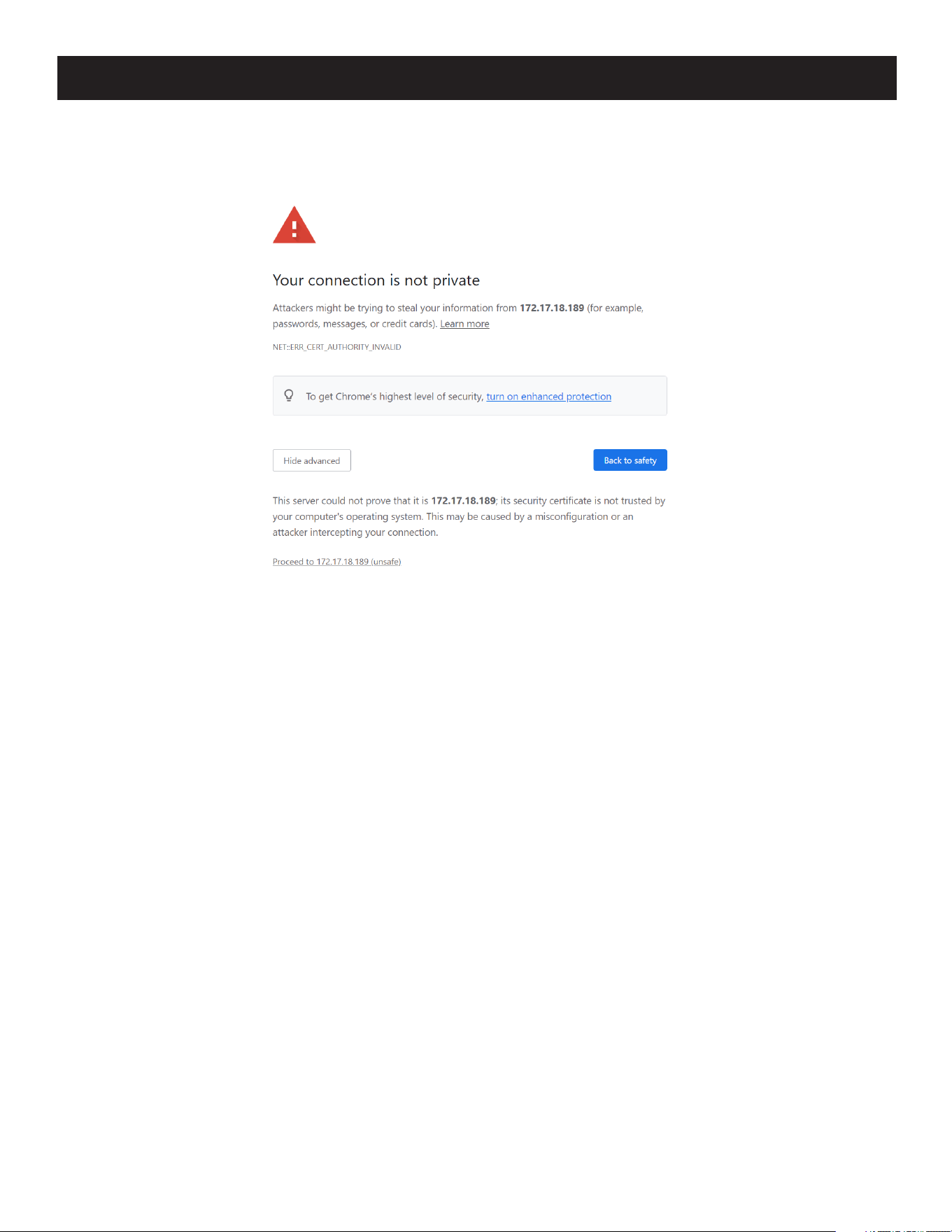
7.1.2 Trusted Certificates
When you try to log in to the B064C-16-1X1-IP from your Web browser, a Security Alert message will appear to inform
you the device’s certificate is not trusted and ask if you want to proceed.
The certificate can be trusted, but the alert is triggered because the certificate’s name is not found on Microsoft’s list of
Trusted Authorities. You have two options: 1) Ignore the warning and click Proceed; or 2) Install the certificate and have
it be recognized as trusted.
• If you are working on a computer at another location, accept the certificate for just this session by clicking Yes.
• If you are working at your own computer, install the certificate on your computer (see below for details). After the
certificate is installed, it will be recognized as trusted.
34
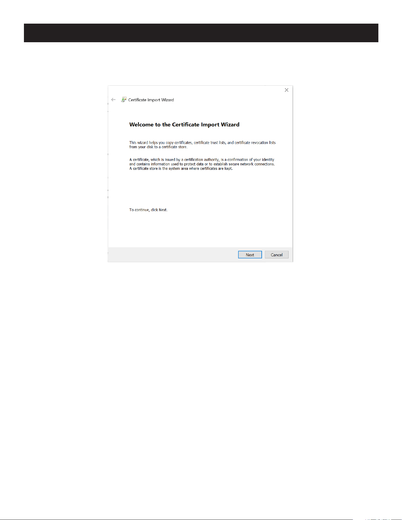
Installing the Certificate
To install the certificate:
1. Go to Browser’s security setting and look for HTTPS/SSL certificate section. Start the Certificate Import Wizard.
2. Follow the steps and import the trusted certificate into the Trusted Root Certification Authorities Section, then click
Finish.
3. Follow the Installation Wizard instructions to complete the installation. Unless you have a specific reason to choose
otherwise, accept the default options.
7. Administration
35
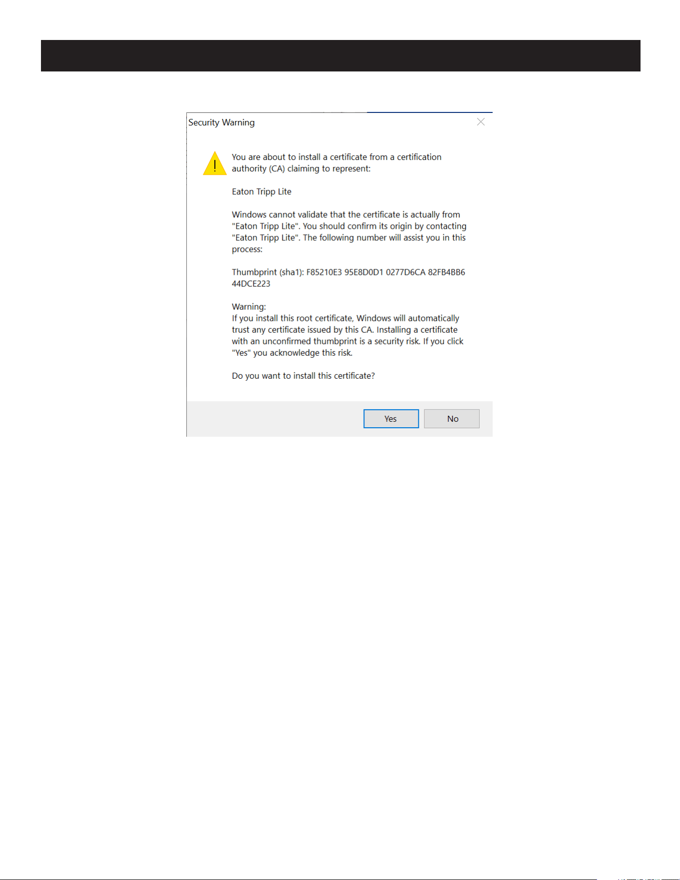
7. Administration
4. The Wizard will present a caution screen. Click Yes.
5. Click Finish to complete the installation.
6. Click OK to close the dialog box.
7.1.3 Self-Signed Private Certificates
If you wish to create your own self-signed encryption key and certificate, a free utility (openssl.exe) is available for
download at www.openssl.org. To create your private key and certificate:
1. Go to the directory where you downloaded and extracted openssl.exe.
2. Run openssl.exe with the following parameters:
openssl req -new -newkey rsa:1024 -days 3653 -nodes -x509
-keyout CA.key -out CA.cer -config openssl.cnf
Notes:
• The command should be entered all on one line ( do not press [Enter] until all parameters have been keyed in).
• If there are spaces in the input, surround the entry in quotes (e.g., “Eaton Corporation”).
To avoid inputting information during key generation. the following additional parameters can be used: /C /ST /L /O /
OU /CN /emailAddress.
Example
openssl req -new -newkey rsa:1024 -days 3653 -nodes -x509
-keyout CA.key -out CA.cer -config openssl.cnf -subj
/C=yourcountry/ST=yourstateorprovince/L=yourlocationor city/O=yourorganiztion/
OU=yourorganizationalunit/ CN=yourcommonname/[email protected]
Importing Files
Once the openssl.exe program completes, two files - CA.key (the private key) and CA.cer (the self-signed SSL certificate)
- are created in the directory that you ran the program from. These are the files that you upload in the Private Certificate
panel of the Security page.
36
7. Administration
7.2 Super Administrator Setup
7.2.1 First-Time Setup
Once the KVM over IP switch has been connected, the Super Administrator will need to set up the unit for user
operation. This involves setting the network parameters and changing the default Super Administrator login. The most
convenient way to do this for the first time is from the local console.
Note: For remote methods of setting up the network, see 7.1 IP Address Determination.
At the local console, a login prompt appears on the console monitor:
Since this is the first time you are logging in, use the default Username: administrator and the default Password:
password.
Note: For security purposes, the system will prompt you to change the login password. The password must be different from your login
password.
Once you successfully log in, the Local Console Main Page will appear:
37
7. Administration
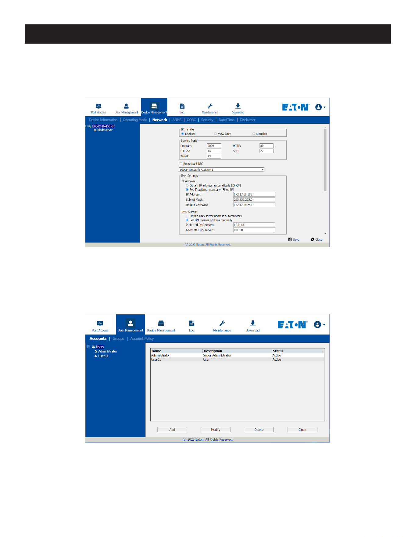
Network Setup
To set up the network, do the following:
1. Click the Device Management tab.
2. Select the Network tab.
3. Fill in the fields according to the information provided under XX Network.
Changing the Super Administrator Login
1. At the top of the screen, click the User Management tab.
The User Management page has a list of Users and Groups in the Sidebar at the left and a more detailed list of users
(and user information) in the large central panel. Since this is the first time the page is being accessed, only the Super
Administrator will appear:
38
7. Administration
2. Click Administrator in the left panel.
or
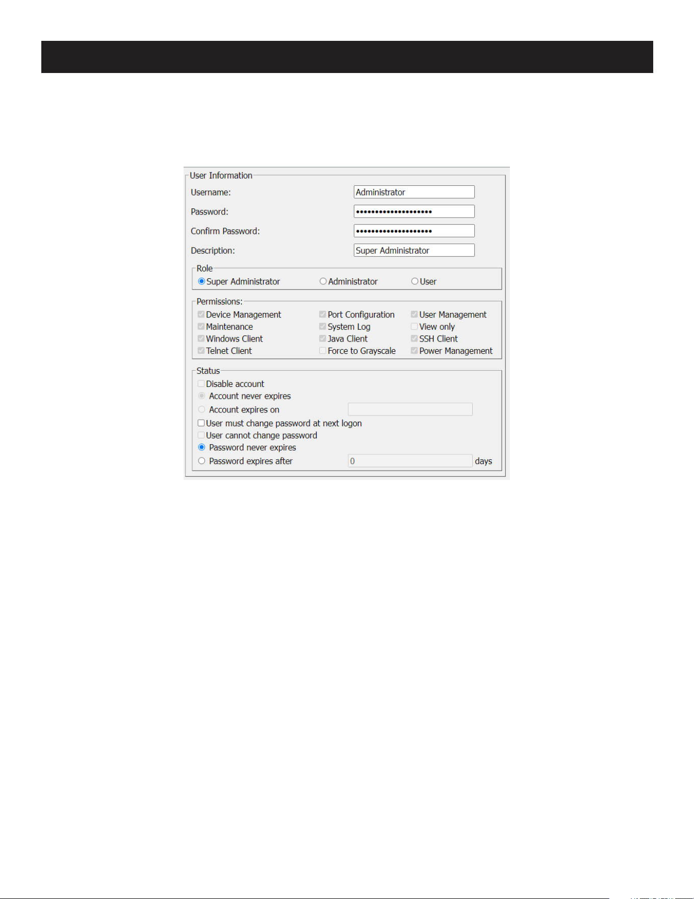
Select administrator in the central panel, then click Modify at the bottom of the page.
The User Information page will appear:
3. Change the Username and Password to something unique.
4. Enter the password again in the Confirm Password field to confirm it is correct.
5. Click Save.
6. When the dialog box informing you that the change completed successfully appears, click OK.
7. Click on another item on the Local Console Main Page to close this page.
7.2.2 Moving On
After setting up the network and changing the default Super Administrator password, you can proceed to other
administration activities. These include User Management, Device Management and Firmware Upgrade Maintenance.
These activities can be accomplished using any of the KVM over IP switch’s GUI utilities. These include the Local
Console, the browser-based Windows GUI, the browser-based Java Client Viewer, the stand-alone Windows Client AP
and the stand-alone Java Client AP. Choose the approach that suits you best.
Note: Firmware Upgrade Maintenance cannot be performed from the local console. You must log in remotely with one of the KVM over IP
switch’s other GUI utilities for this operation.
39
7. Administration
7.3 Logging In
KVM over IP switches can be accessed from a local console, an Internet browser, a Windows application (AP) program
and a Java application (AP) program.
No matter which access method you choose, the KVM over IP switch’s authentication procedure requires you to submit
a valid username and password. If you supply invalid login information, the authentication routine will return an Invalid
Username or Password or Login Failed message. If you see this type of message, log in again with a correct username
and password.
Note: If the number of invalid login attempts exceeds a specified amount, a time out period is invoked. You must wait until the time out
period expires before you can attempt to log in again.
7.3.1 Local Console Login
When the local console is attached and there is no user logged in, the KVM over IP switch’s login screen appears:
Key in your username and password, then click Login to open the Local Console Main Page. The Local Console Main
Page is similar to the Web Browser, WinClient and Java Client Main Pages.
Note: If you are the administrator and are logging in for the first time, use the default username (administrator) and the default
password (password). For security purposes, the system will prompt you to change the login password. The password must be different
from your login password.
40
7. Administration
7.3.2 Browser Login
KVM over IP switches can be accessed via an Internet browser running on any platform. To access the switch:
1. Open the browser and specify the IP address of the switch you want to access in the browser’s location bar.
Note: For security purposes, a login string may have been set by the administrator. By default, there is no login string. If so, you must
include a forward slash and the login string along with the IP address when you log in. For example:
192.168.0.100/B064C161X1IP
2. When a Security Alert dialog box appears, accept the certificate (see 7.1.2 Trusted Certificates for details). If a
second certificate appears, accept it as well.
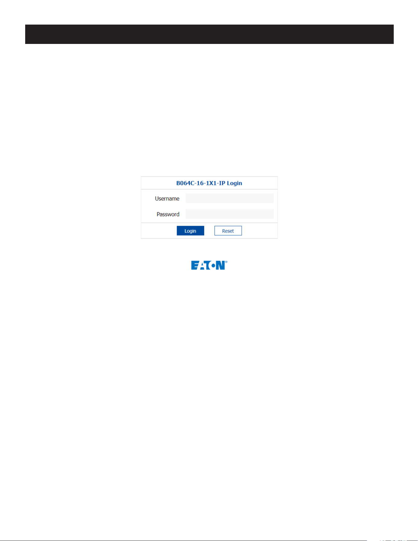
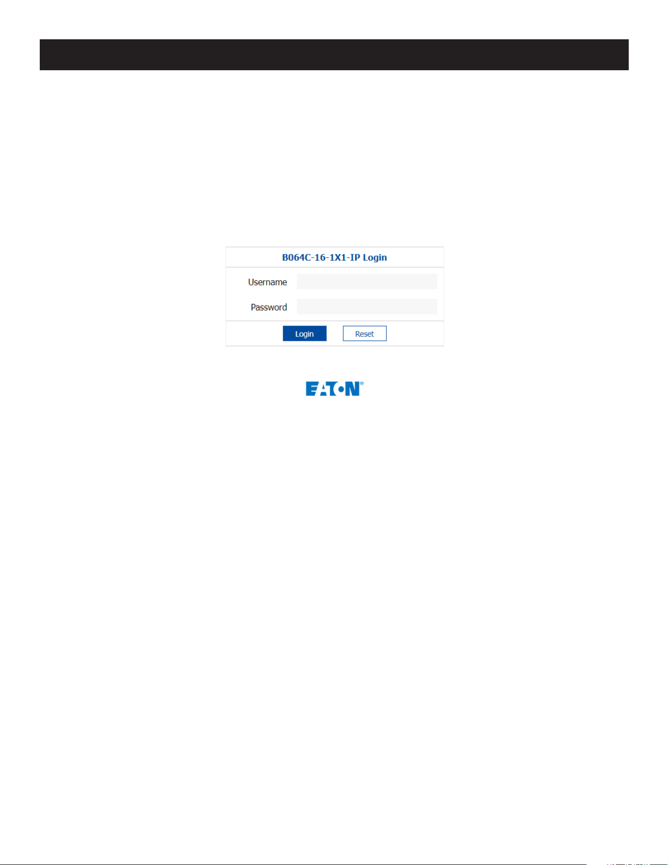
Once you accept the certificate(s), the login page will appear:
3. Provide your username and password (set by the administrator), then click Login to open the Web Main Page.
Note: If you are the administrator and are logging in for the first time, use the default username (administrator) and the default
password (password). For security purposes, the system will prompt you to change the login password. The password must be different
from your login password.
7.3.3 Windows Client AP Login
The Windows AP Client allows direct remote access to Windows systems users without having to go through a browser
(although you initially download the Windows AP Client program from the browser page, see 7.10 Download for more
information). To connect to the B064C-16-1X1-IP, go to the location on your hard disk that you downloaded the
Windows AP Client program and double-click its icon (WinClient.exe).
41
7. Administration
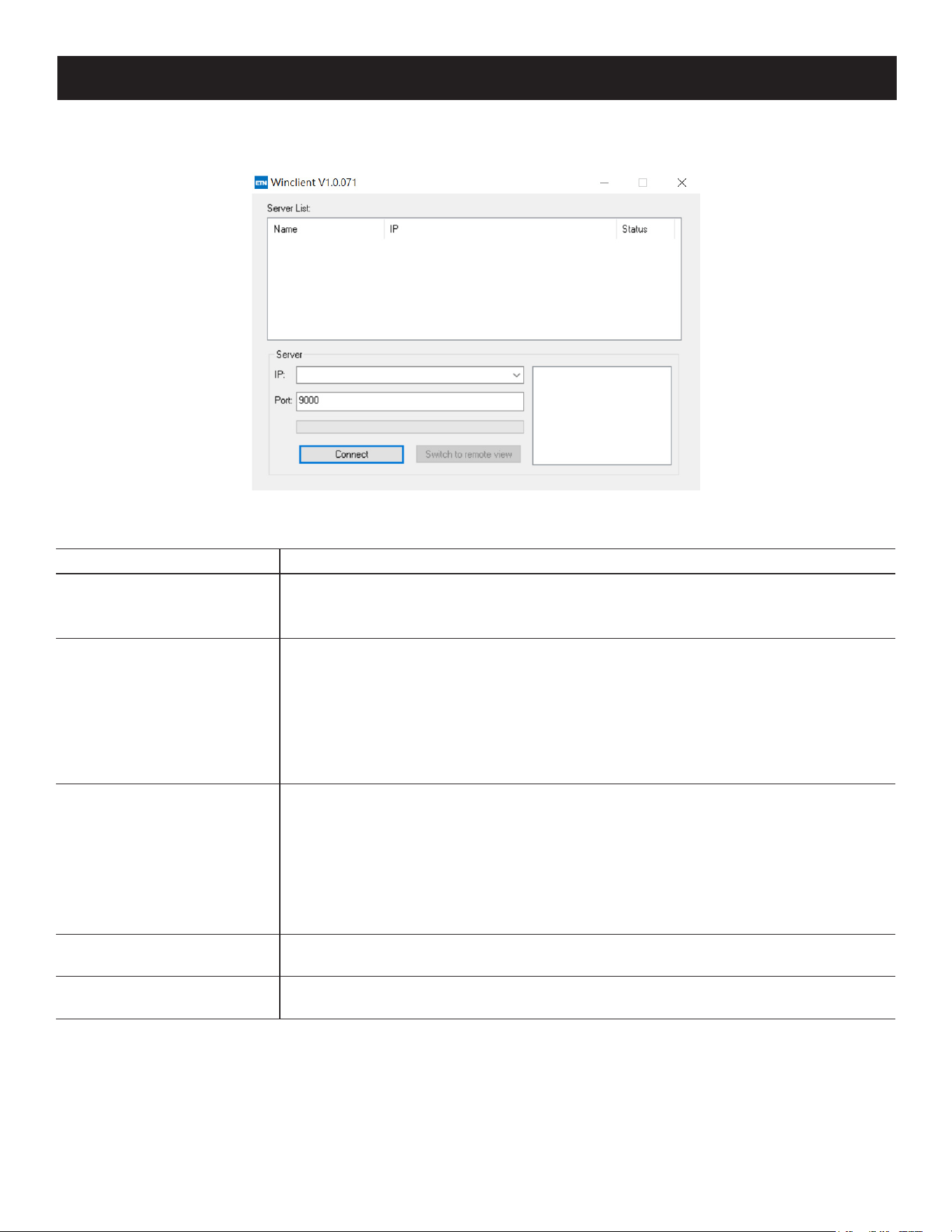
To connect to the B064C-16-1X1-IP, click the WinClient.exe program icon (on your desktop) to access the Windows
Client Connection screen:
Windows Client AP Connection Screen
Item Description
Menu Bar The Menu Bar contains two items: File and Help.
• The File Menu allows the operator to Create, Save and Open user created Work les).
• The Help Menu displays the WinClient AP version.
Server List Each time the WinClient.exe le is run, it searches the user’s local LAN segment for
KVM over IP switches and lists whichever ones it nds in this box. If you want to
connect to one of these units, double-click it.
Notes:
The switch will not appear in the list unless its Enable Device List conguration parameter has been
enabled.
Only units whose Access Port settings for Program match the number specied for Port in the Server
area of this dialog box appear in the Server List window.
Server This area is used when you want to connect to a KVM over IP switch at a remote
location. You can drop down the IP list box and select an address from the list. If the
address you want is not listed, you can key in the target IP address in the IP eld and
its port number in the Port eld (if you do not know the port number, contact your
Administrator).
• When the IP address and Port number have been specied, click Connect.
• When you have nished with your session and come back to this dialog box, click
Disconnect to end the connection.
Message Panel Located just to the right of the Server panel, the Message panel lists status messages
regarding the connection to the KVM over IP switch.
Switch to Remote View Once you have been authenticated, this button becomes active. Click it to switch to the
GUI Main Page.
42
7. Administration
Connecting - Windows Client AP
1. From the Server List box, double-click the device that you wish to connect to.
- Or -
Specify its IP address and port number in the Server IP and Port input boxes.
2. Click Connect.
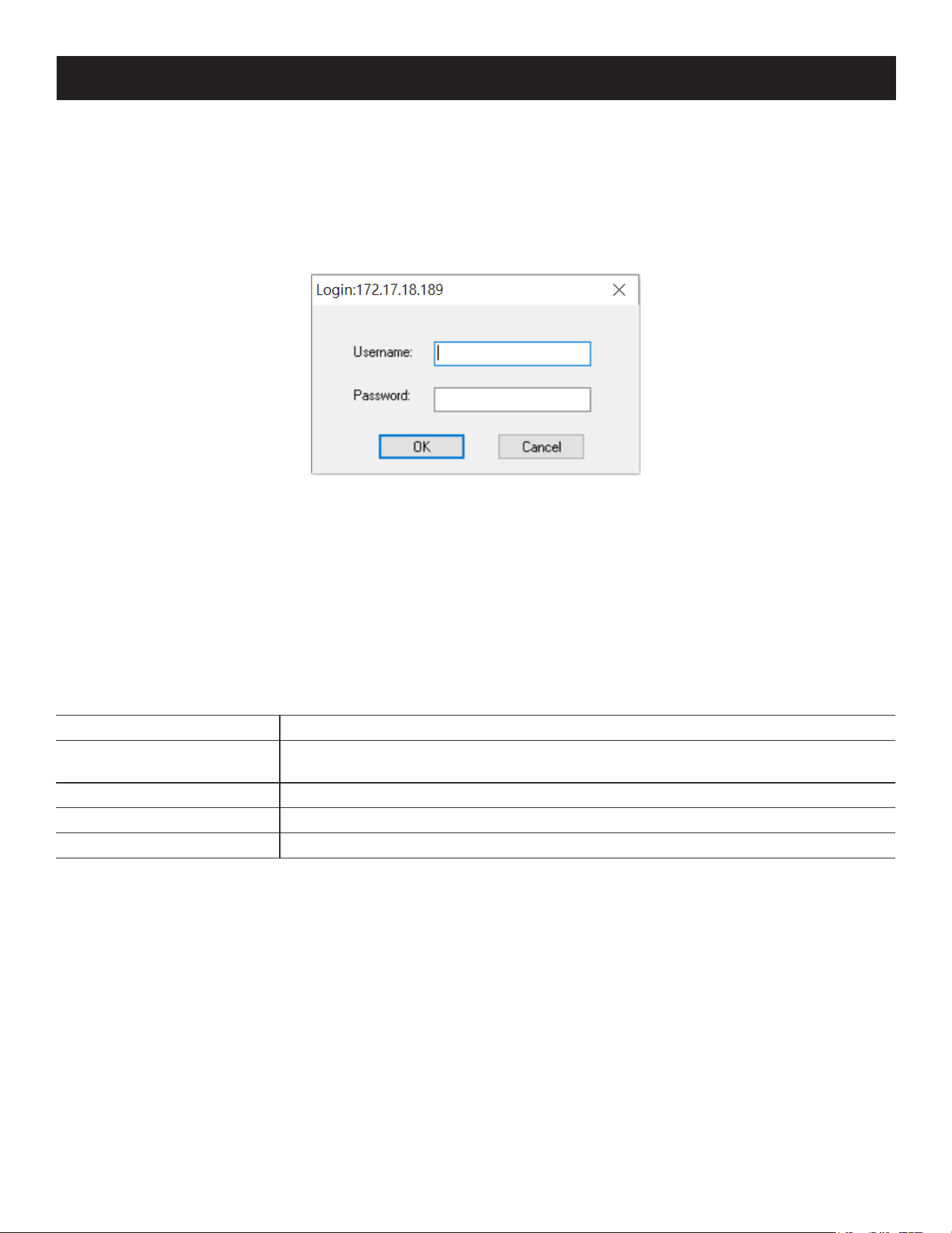
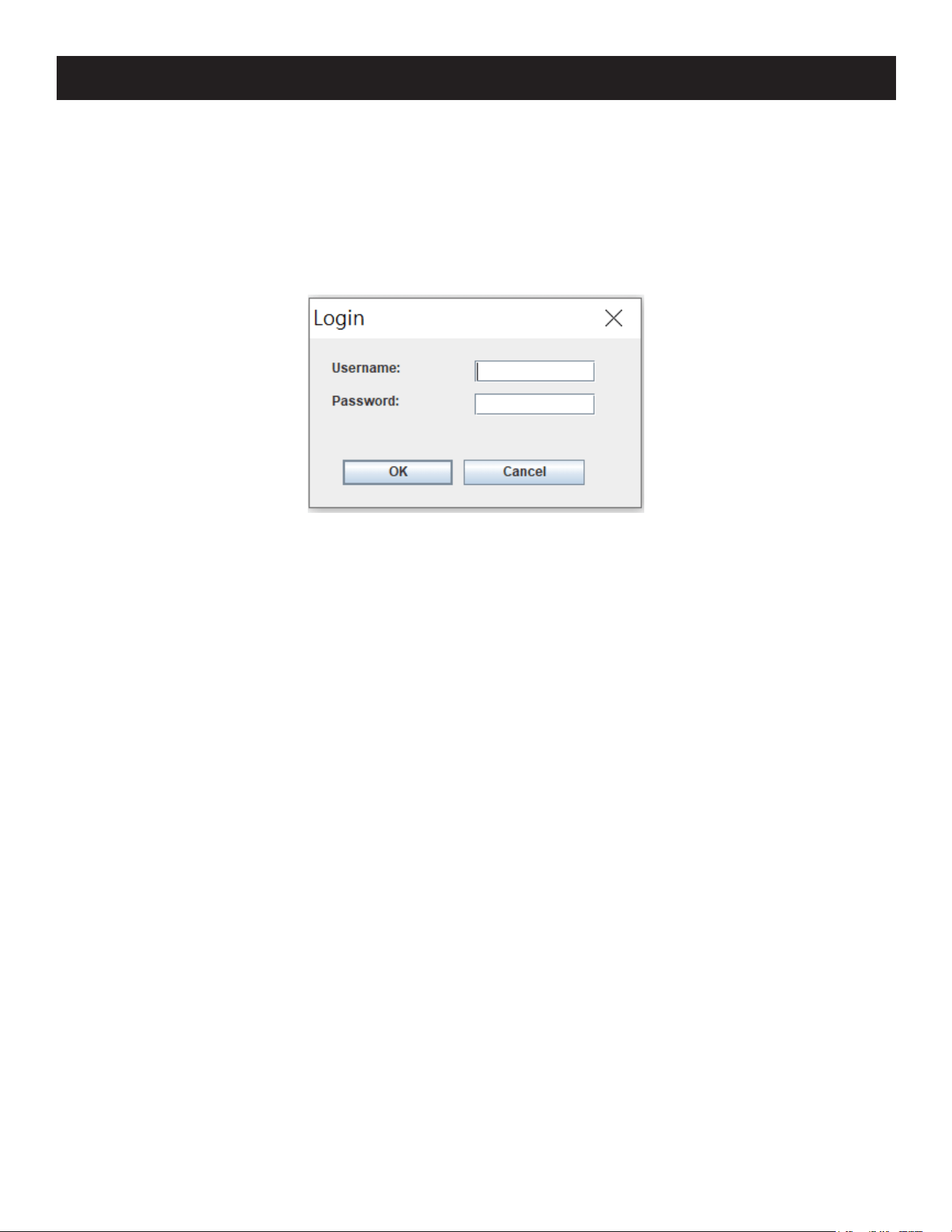
The Login dialog box appears:
3. Key in a valid Username and Password, then click OK.
4. Once you have been authenticated, the Switch to Remote View button becomes active. Click it to connect to the
switch and open its GUI Main Page.
File Menu
The File Menu allows the operator to Create, Save and Open user created Work files. A Work File consists of all the
information specified in a Client session. This includes the Server List and Server IP list items, as well as the Hotkey
settings.
Whenever a user runs the Client program, it opens with the values contained in the current work file. The current work
file consists of the values that were in effect the last time the program was closed.
The File menu consists of the following items:
Item Description
New Allows the user to create a named work le so its values will not be lost and it will be
available for future recall.
Open Allows the user to open a previously saved work le and use the values contained in it.
Save Allows the user to save the values presently in eect as the current work le.
Exit Exits the WinClient.
43
7. Administration
7.3.4 Java Client AP Login
In those cases in which the Administrator does not want the KVM over IP switch to be available via browser access, but
the local client users aren’t running Windows, the Java AP Client provides direct remote access to non-Windows systems
users (although you initially download the Java AP Client program from the browser page, see 7.10 Download).
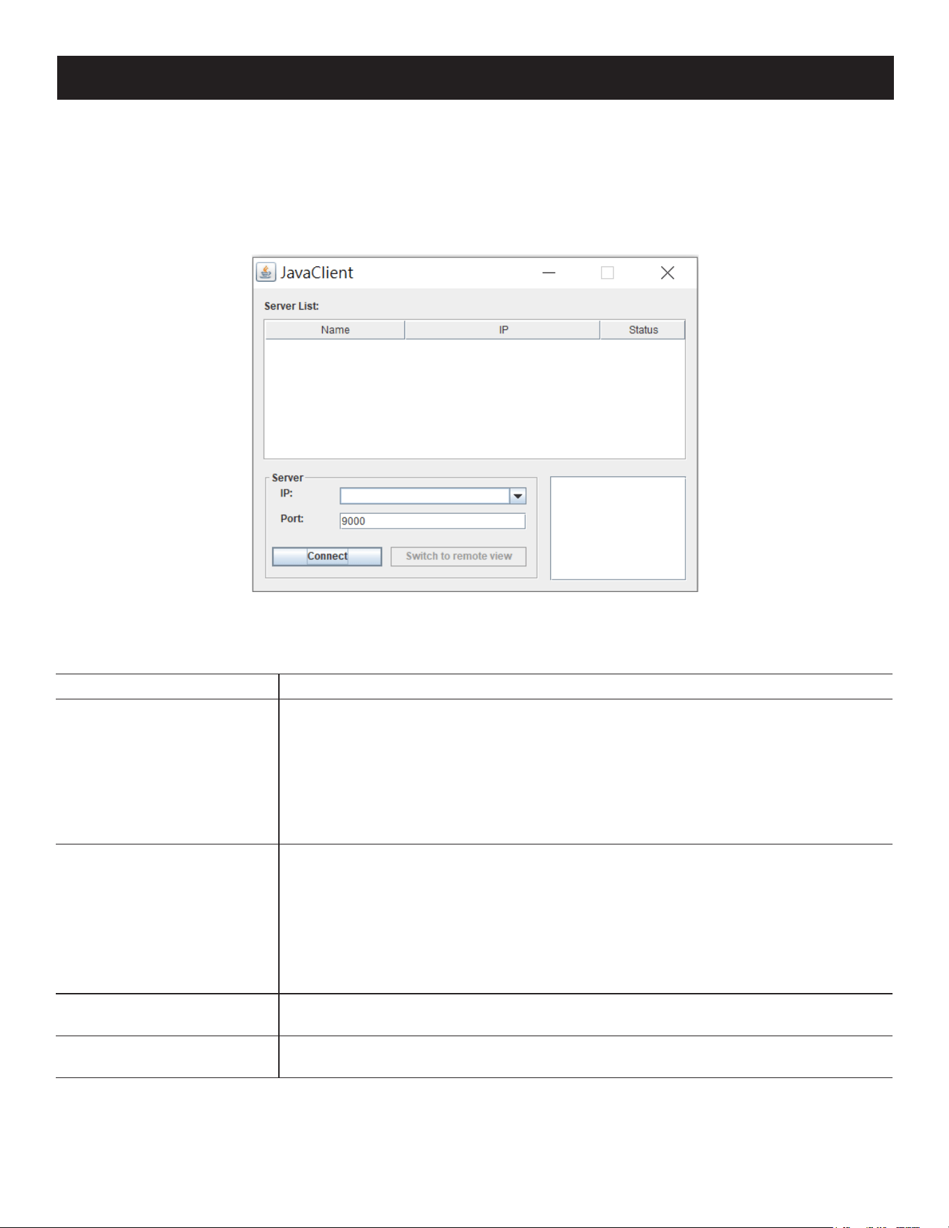
To connect to the B064C-16-1X1-IP, go to the location on your hard disk that you downloaded the Java AP Client
program to, and double-click its icon (JavaClient.jar) to open the Java Client Connection Screen:
Java Client AP Connection Screen
A description of the Connection Screen is provided in the following table:
Item Description
Server List Each time the JavaClient.jar le is run, it searches the User’s local LAN segment for KVM
over IP switches and lists whichever ones it nds in this box. If you want to connect to
one of these units, double-click it.
Notes:
• The switch will not appear in the list unless its Enable Device List conguration parameter has been
enabled.
• Only units whose Access Port settings for Program match the number specied for Port in the
Server area of this dialog box appear in the Server List window.
Server This area is used when you want to connect to a KVM over IP switch at a remote
location. You can drop down the IP list box and select an address from the list. If the
address you want is not listed, you can key in the target IP address in the IP eld and
its port number in the Port eld (if you do not know the port number, contact your
Administrator.)
• When the IP address and Port number have been specied, click Connect.
• When you have nished with your session and come back to this dialog box, click
Disconnect to end the connection.
Message Panel Located just to the right of the Server panel, the Message panel lists status messages
regarding the connection to the KVM over IP switch.
Switch to Remote View Once you have been authenticated, this button becomes active. Click it to switch to the
GUI Main Page.
44
Connecting - Java Client AP
To connect to a KVM switch, do the following:
1. From the Server List box, double-click the device that you wish to connect to.
- Or -
Specify its IP address and port number in the Server IP and Port input boxes.
2. Click Login.
The Login dialog box appears:
3. Key in a valid username and password, then click OK.
4. Once you have been authenticated, the Remote View button becomes active:
5. Click it to connect to the switch and access its GUI Main Page.
7.4 User Interface
Once you have successfully logged in, the B064C-16-1X1-IP user interface Main Page will appear. The appearance of the
page may vary slightly, depending on which method was used to log in.
7. Administration
45
7. Administration
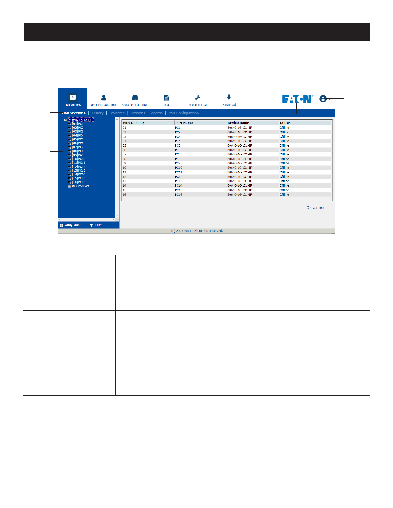
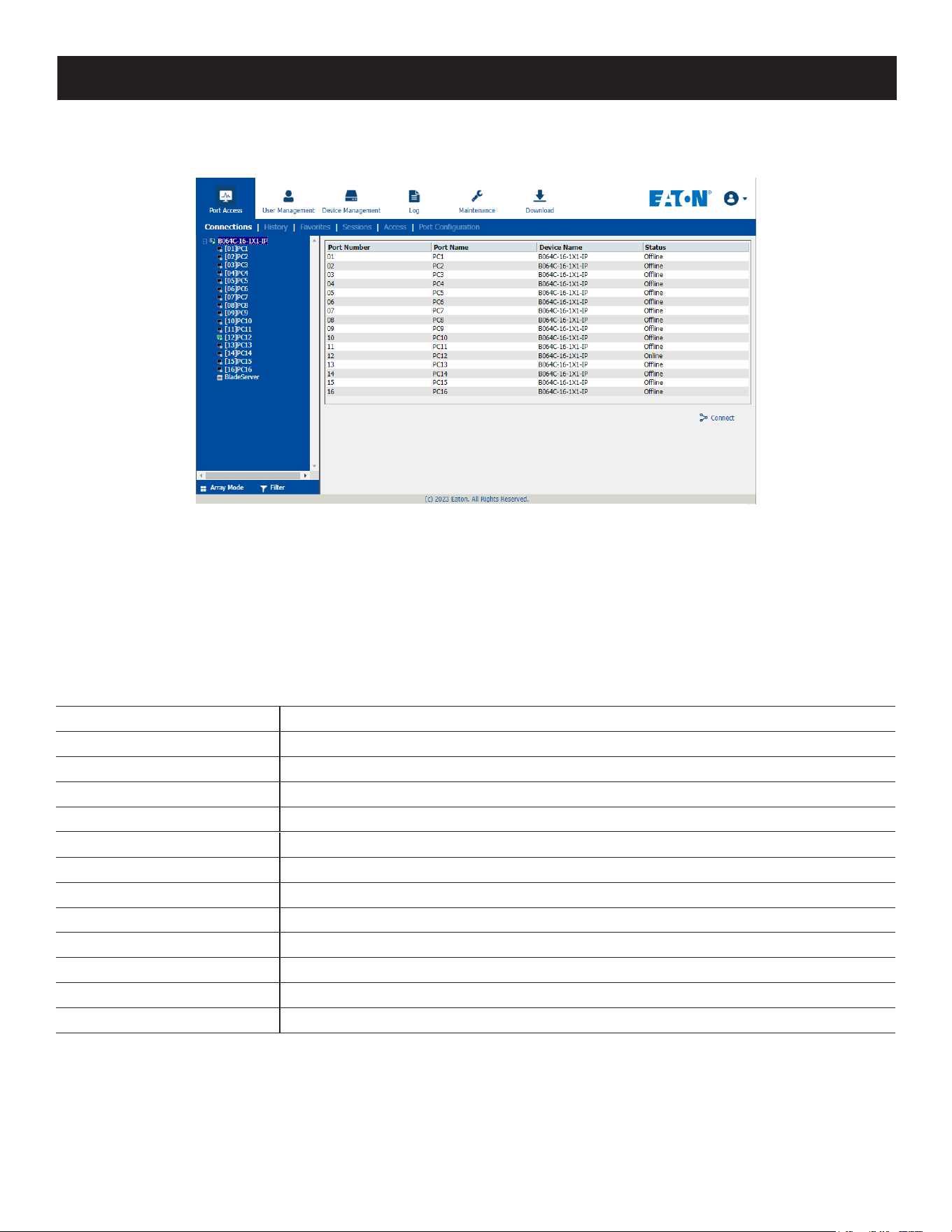
7.4.1 Web Browser Main Page
To ensure multi-platform operability, access to the B064C-16-1X1-IP can be accomplished with most standard web
browsers. Once users log in and are authenticated, the Web Browser Main Page will appear with the Port Access page
displayed:
Note: The above screen shows an administrator’s page. Depending on a user’s type and permissions, not all of these elements may
appear.
1
Tab Bar
The tab bar contains the B064C-16-1X1-IP main operation categories. The items that
appear in the tab bar are determined by the user's type and the authorization options
that were selected when the user's account was created.
2
Menu Bar
The menu bar contains operational sub-categories that pertain to the item selected
in the tab bar. The items that appear in the menu bar are determined by the user's
type and the authorization options that were selected when the user's account was
created.
3
Sidebar
The Sidebar provides a tree view listing of ports that relate to the various tab bar and
menu bar selections. Clicking a node in the Sidebar will open a page with the details
that are relevant to it.
There is a Filter button at the bottom of the Sidebar that lets you expand or
narrow the scope of the ports that appear in the tree.
4
Eaton Logo Eaton Logo directs user to the ocial Eaton website https://tripplite.eaton.com/.
5
User Settings
Click this button for user information, congure user preferences settings, change
password, logout and online help.
6
Interactive Display Panel
This is your main work area. The screens that appear reect your menu choices and
Sidebar node selection.
11
22
33
55
44
66
46
7. Administration
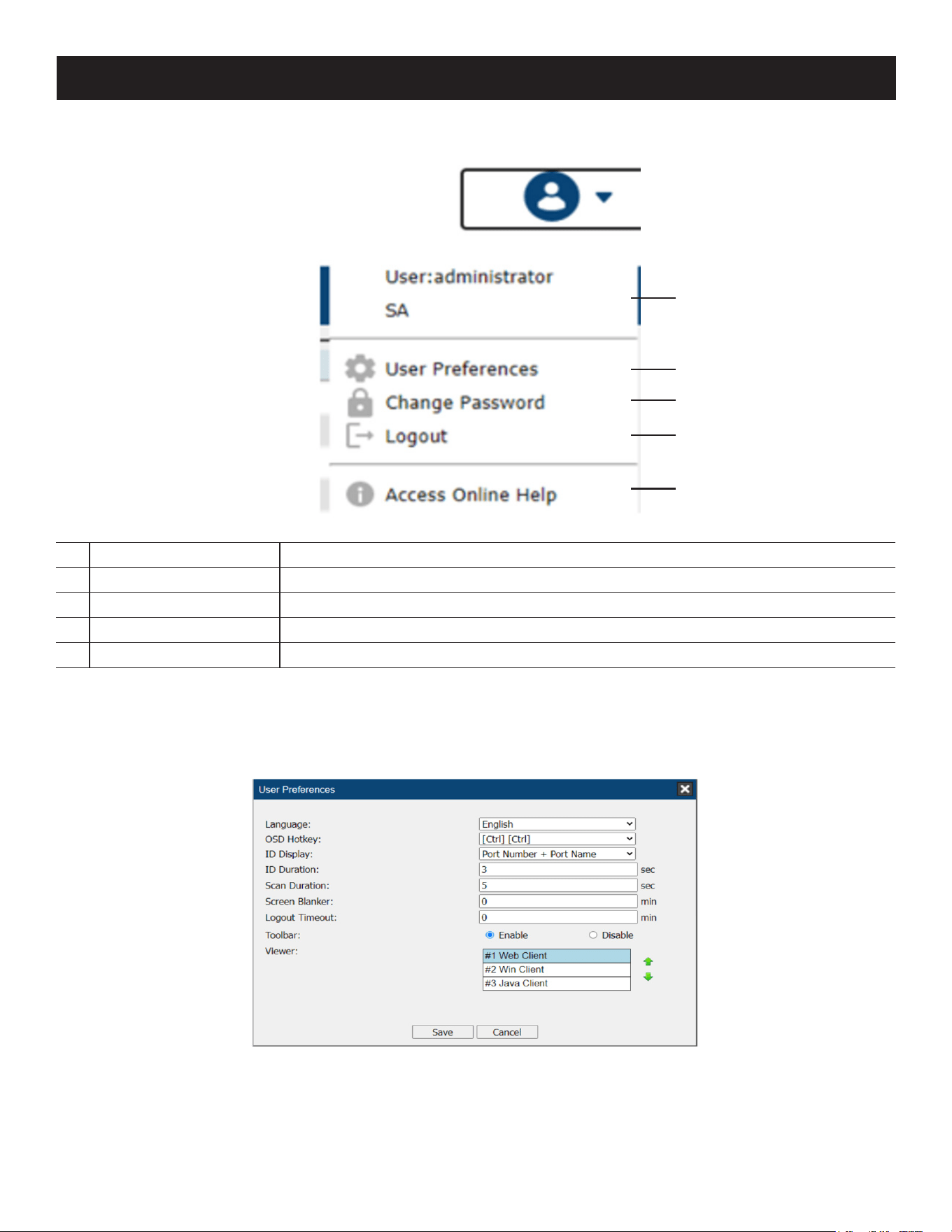
User Settings
1
User Information Displays the user information and description.
2
User Preferences Congures the user preference settings.
3
Change Password Change the login password.
4
Logout Log out and end the session.
5
Access Online Help Click to visit the Eaton Website.
User Preferences
The User Preferences page allows users to set up their own individual working environments. The switch stores a
separate configuration record for each user profile and sets up the working configuration according to the Username
that was keyed into the Login dialog box:
11
22
33
44
55
47
7. Administration
Setting Function
Language Selects the language the interface displays in.
OSD Hotkey Selects which Hotkey controls the GUI function: [Scroll Lock]. [Scroll Lock] is the
default. To select a dierent combination, click the arrow at the right of the box to
drop down the list of choices.
ID Display Selects how the Port ID is displayed: the Port Number alone (PORT NUMBER), the Port
Name alone (PORT NAME); or the Port Number plus the Port Name (PORT NUMBER +
PORT NAME). The default is PORT NUMBER + PORT NAME.
ID Duration Determines how long a Port ID displays on the monitor after a port change has taken
place. You can choose an amount from 1—255 seconds. The default is 3 Seconds. A
setting of 0 (zero) means the Port ID is always on.
Scan Duration Determines how long the focus dwells on each port as it cycles through the selected
ports in Auto Scan Mode. Key in a value from 1—255 seconds. The default is 5
seconds; a setting of 0 disables the Scan function.
Screen Blanker If there is no input from the console for the amount of time set with this function,
the screen is blanked. Key in a value from 1—30 minutes. A setting of 0 disables this
function. The default is 0 (disabled).
Note: Although this function can be set from either the local console or a remote login, it only
aects the local console monitor.
Logout Timeout If there is no user input for the amount of time set with this function, the user is
automatically logged out. A login is necessary before the KVM over IP switch can be
accessed again.
Toolbar Selects whether the Port Toolbar is enabled when a port is accessed.
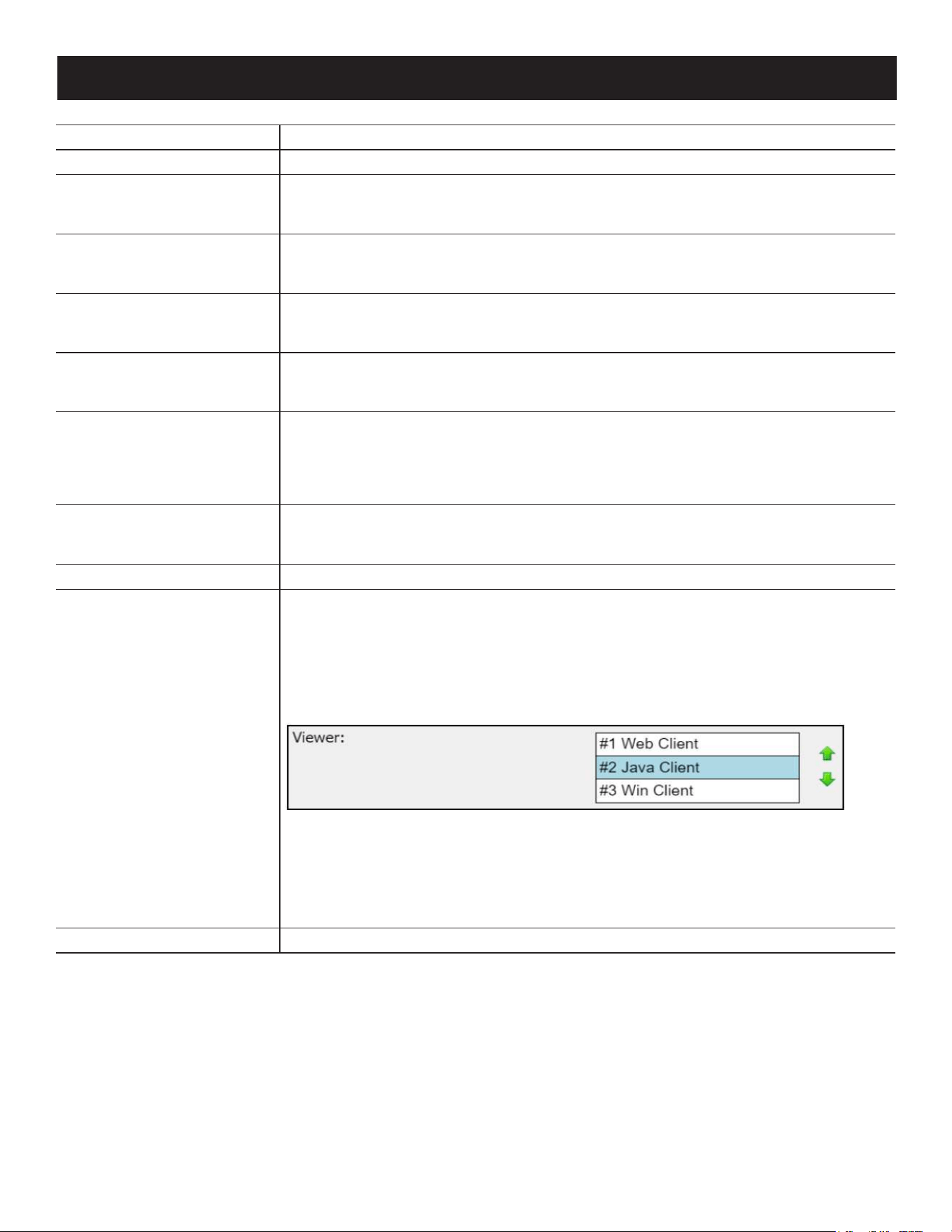
Viewer* In the browser version of this page, a Viewer section is available. You can choose which
viewer method is preferred when connecting to a port by clicking the up or down
arrow to shift viewer method position around.
Usable viewers are automatically determined by the status of the system at the time of
the login and by the type of browser.
When you try to connect to a port (double-click the port or select a port and click
Connect), the system will use the viewer according to the viewer list.
• The top-most method is the most preferred method and is listed as #1 (Web Client
by default).
• If the preferred method is supported when connecting to a port, the system will try
connecting using the preferred method.
• If the method is not supported, the system will try connecting using the next
method, and try the last method last.
Save Click Save to save any changes made to the User Preferences settings.
Notes:
• *This item is only available with the Browser version.
• The local console’s User Preferences page additionally (and exclusively) provides the beeper setting for users to turn the device’s beeper
on (default) or off.
48
Tab Bar
The number and type of icons that appear on the Tab Bar at the top of the page are determined by the user’s type
(Super Administrator, Administrator, User) and the permissions assigned when the user’s account was created. The
functions associated with each of the icons are explained in the table below:
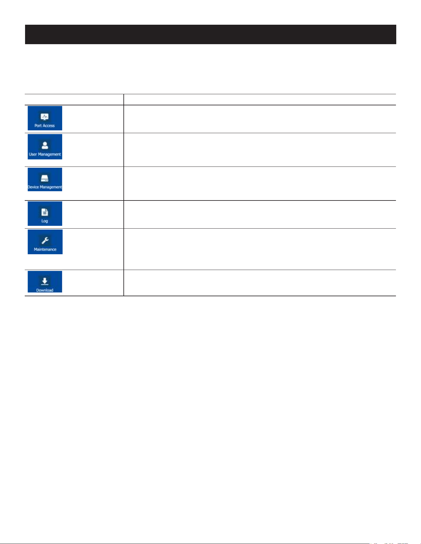
Icon Function
Port Access: The Port Access page is used to access and control the devices on the
KVM over IP switch installation. This page is available to all users.
User Management: The User Management page is used to create and manage Users
and Groups. It can also be used to assign devices to them. This tab is available to the
Super Administrator as well as administrators and users who have been given User
Management permission. The tab does not appear for other administrators and users.
Device Management: The Device Management page is used to congure and
control the overall operation of the KVM over IP switch. This page is available to the
Super Administrator, as well as administrators and users who have been given Device
Management permission. The tab does not appear for other administrators and users.
Log: The Log page displays the contents of the log le.
Maintenance: The Maintenance page is used to install new rmware; backup and
restore conguration and account information; ping network devices; and restore
default values. This page is available to the Super Administrator (and Administrators
and Users with Maintenance permission). The icon does not display on the page of
ordinary administrators and users.
Download: Users can click this icon to download AP versions of the Windows Client;
the Java Client; and the Log Server. This page is available to all users. The programs
that can be downloaded depend on the user’s permissions.
7. Administration
49
7. Administration
7.4.2 AP GUI Main Page
With WinClient AP and Java Client AP access, once users log in (see 7.3 Logging ln), the GUI Main Page will open:
The GUI Main Page is similar to the Web Browser. The differences between them are as follows:
1. The AP GUI version does not have a menu bar below the tab bar; it instead has a series of tabs like a notebook. Like
the Web Browser interface, the makeup of the tabbed notebook changes depend on the items selected on the main
Tab Bar and in the Sidebar.
2. In addition to Filter, there are also buttons for Scan and Array Mode at the bottom of the Sidebar. These functions
are discussed in 7.5 Port Access.
3. There is a hidden Control Panel at the upper or lower center of the screen that becomes visible when you hover
your cursor over it (the default is at the upper center of the screen).
4. The GUI can be navigated via the keyboard as shown in the table below:
Keys Action
Ctrl + P Opens the Port Access page.
Ctrl + U Opens the User Management page.
Ctrl + D Opens the Device Management page.
Ctrl + L Opens the Log page.
Ctrl + M Opens the Maintenance page.
Ctrl + A Opens the Download page.
F1 To see About information
F2 To edit the port name of the selected port.
F4 Selects the Sidebar (left) panel.
F5 Selects the main (right) panel
F7 Closes the GUI.
F8 To log out.
50
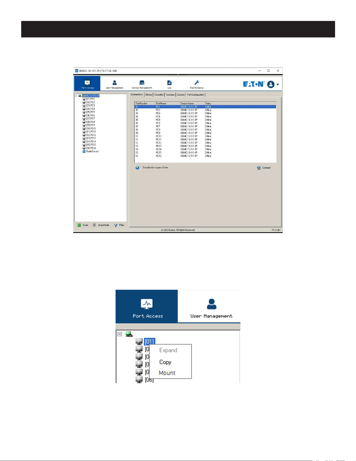
7.4.3 Local Console GUI Main Page
The Local Console GUI Main Page is similar to the Java and Windows AP GUI Main Page:
The major difference is that the Local Console Main Page does not have a tab for Download.
Mounting Virtual Media Locally
Local console supports virtual media mounting. To mount a virtual media:
1. Plug the USB flash drive into the target server locally.
2. On your local console, right-click the server in the sidebar and click Mount.
7. Administration
51
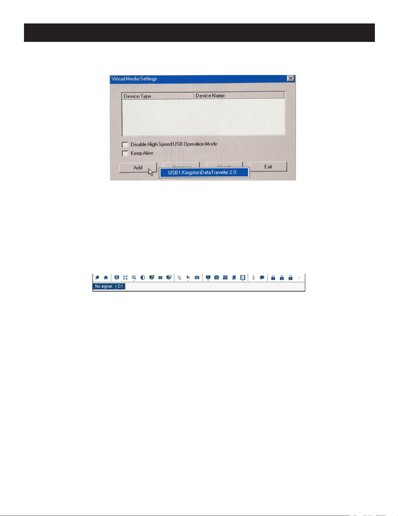
7. Administration
3. On the Virtual Media Settings dialog box that appears, click Add to select your virtual media.
Note: The mounting virtual media settings are similar to those of via Windows / Java Client Viewer.
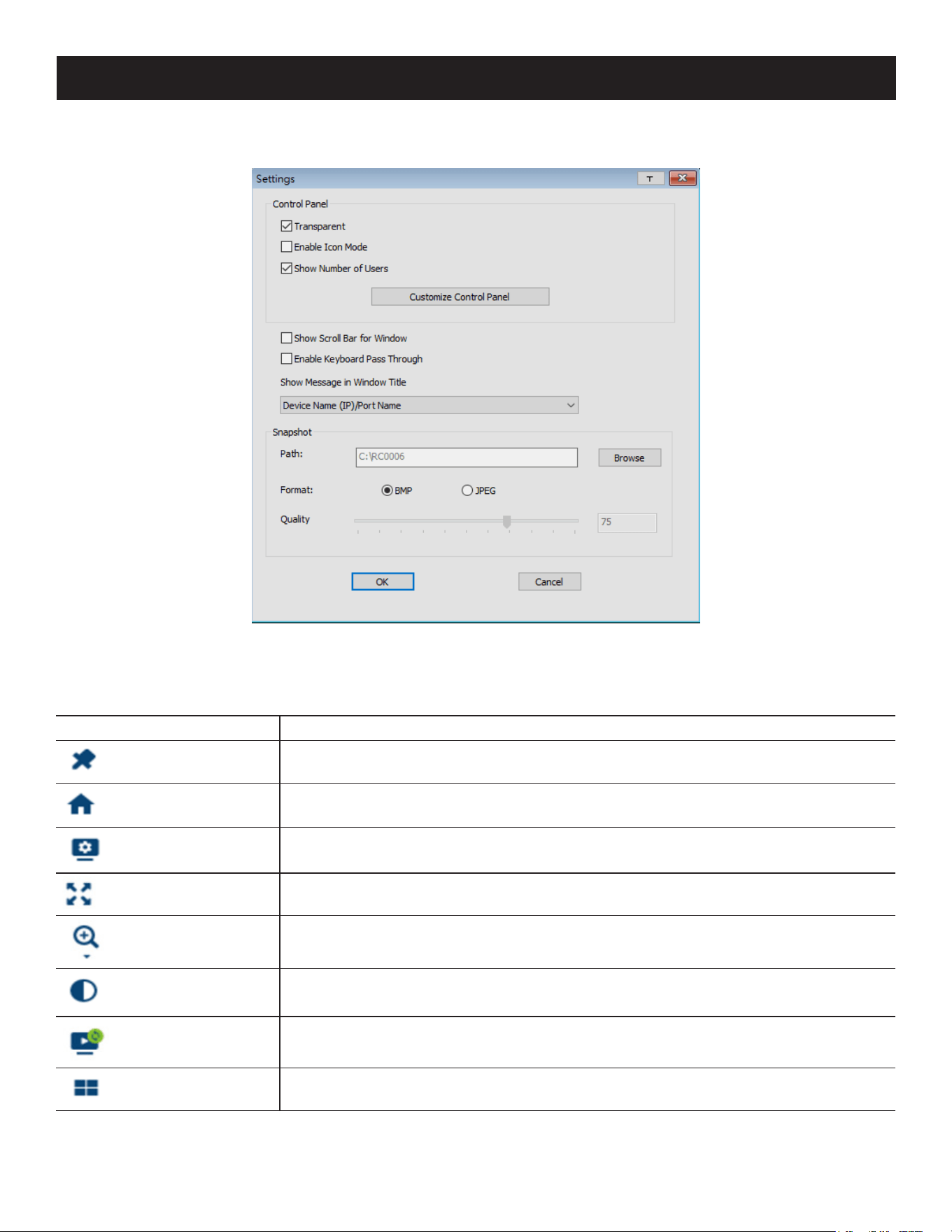
7.4.4 Control Panel
WinClient Control Panel
Since the WinClient Control Panel contains the most complete functionality, this section describes the WinClient Control
Panel. Although the Java Control Panel does not enable all the features as the WinClient Control Panel, the functions
they do share are the same and you can refer to the information described here when using it.
The Control Panel is hidden at the upper or lower center of the screen (the default is at the lower center) and will
become visible when your mouse over it. The panel consists of three rows: an icon row at the top, and text rows below
it:
Note: The above image shows the complete Control Panel. The icons that appear can be user selected.
• By default, the left of the text row shows the video resolution of the remote display. As the mouse pointer moves
over the icons in the icon bar, information in the upper text row changes to describe the icon’s function. In addition, if
a message from another user is entered in the message board and you have not opened the message board in your
session, the message will appear in the upper row.
• The right of the row shows the IP address of the device you are accessing at the left of the row. The center of the row
indicates which bus the user is on (the number before the slash), and the total number of users on that bus (the
number behind the slash).
Notes:
• The bus and user information in the center of the row only displays if it has been enabled.
• See 7.11.4 Multiuser Operation for further information regarding the KVM over IP switch’s bus assignments.
52
7. Administration
• Right-clicking in the text row area opens a menu-style version of the toolbar. In addition, it allows you to select
options for the Screen Mode, Zoom, Mouse Pointer type and Mouse Pointer.
• To move the Control Panel to a different location on the screen, place the mouse pointer over the text row area, then
click and drag.
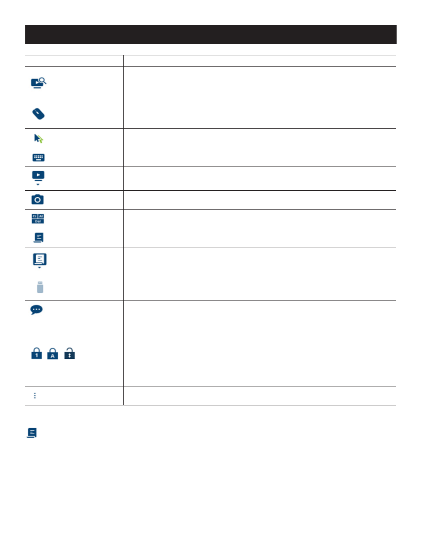
WinClient Control Panel Functions
Icon Function
This is a toggle. Click to make the Control Panel persistent (e.g., always display on top
of other screen elements). Click again to display normally.
Under an accessed port, click to recall the GUI.
Click to open the Video Options dialog box. Right-click to perform a quick AutoSync.
Toggles the display between Full Screen Mode and Windowed Mode.
Click to zoom the remote display window.
Note: This feature is only available in windowed mode (Full Screen Mode is o).
Click to toggle the remote display between color and grayscale views.
Click to perform a video and mouse autosync operation. It is the same as clicking the
AutoSync button in the Video Options dialog box.
Under an accessed port, click to invoke Panel Array Mode (see 7.11.3 Panel Array
Mode).
53
7. Administration
Icon Function
Under an accessed port, click to begin Auto Scan Mode. The KVM over IP switch
automatically switches among the ports that were selected for Auto Scanning with the
Filter function. This allows you to monitor their activity without having to switch among
them manually.
Click to toggle Automatic or Manual mouse sync.
• When the selection is Automatic, a green √ appears on the icon.
• When the selection is Manual, a red X appears on the icon.
Click to select the mouse pointer type.
Note: This icon changes depending on which mouse pointer type is selected.
Click to access the on-screen keyboard.
Click to select the port you wish to connect to.
Click to take a snapshot (screen capture) of the remote display.
Click to send a Ctrl+Alt+Del command to the remote system.
Click to open the Macros dialog box.
Click to display a dropdown list of User macros to access and run macros more
conveniently than using the Macros dialog box.
Click to open the Virtual Media dialog box. The icon changes depending on the status
of the virtual media function.
Note: This icon displays in gray when the function is disabled or not available.
Click to open the Message Board.
These icons show the Num Lock, Caps Lock and Scroll Lock status of the remote
computer.
• When the lock state is On, the LED illuminates orange and the lock hasp is closed.
• When the lock state is O, the LED illuminates blue and the lock hasp is open.
Click on the icon to toggle the status.
Note: These icons and your local keyboard icons are in sync. Clicking an icon causes the
corresponding LED on your keyboard to change accordingly. Pressing a Lock key on your keyboard
will cause the icon’s color to change accordingly.
Click to open more control panel functions.
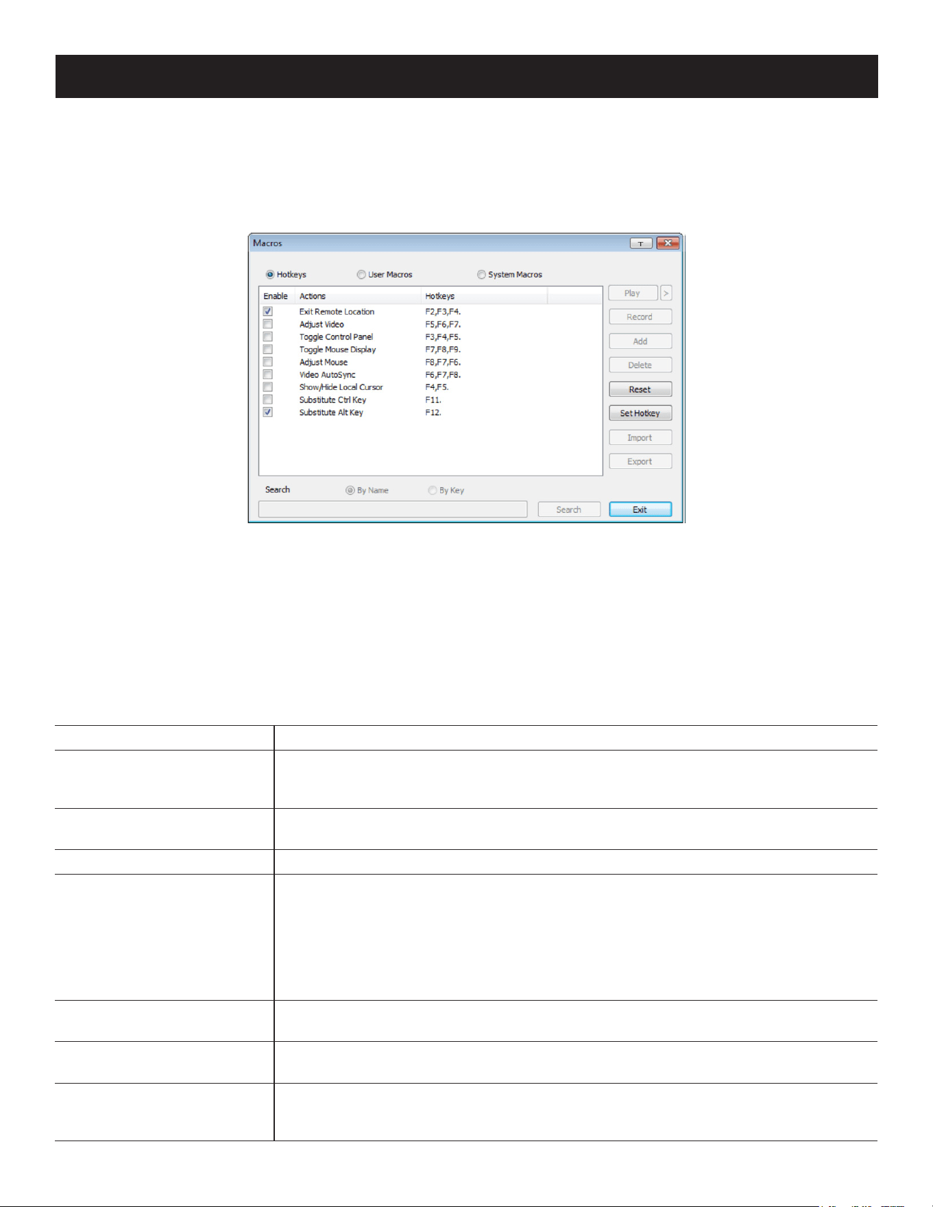
Macros
The Macros icon provides access to three functions found in the Macros dialog box: Hotkeys, User Macros and
System Macros.
54
Hotkeys
Various actions related to manipulating the remote server can be accomplished with hotkeys. The Hotkey Setup utility
(accessed by clicking the icon) lets you configure which hotkeys perform the actions.
The hotkeys that invoke an action are shown to the right of its name. Use the checkbox to the left of an action’s name
to enable or disable its hotkey.
To change the hotkey for an action, do the following:
1. Highlight the Action, then click Set Hotkey.
2. Press your selected Function keys (one at a time). The key names appear in the Hotkeys field as you press them.
• You can use the same function keys for more than one action, so long as the key sequence is not the same.
• To cancel setting a hotkey value, click Cancel; to clear an action’s Hotkeys field, click Clear.
3. Once you have finished keying in your sequence, click Save.
To reset all the hotkeys to their default values, click Reset.
An explanation of the Hotkey actions is provided in the table below:
Action Explanation
Exit Remote Location Breaks the connection to the B064C-16-1X1-IP and returns you to local client
computer operation. This is equivalent to clicking the Exit icon on the Control Panel.
The default keys are F2, F3, F4.
Adjust Video Opens the Video Settings dialog box. This is equivalent to clicking the Video Settings
icon on the Control Panel. The default keys are F5, F6, F7.
Toggle OSD Toggles the OSD Control Panel O and On. The default keys are F3, F4, F5.
Toggle Mouse Display If you nd the display of the two mouse pointers (local and remote) to be confusing or
troublesome, you can use this function to shrink the non-functioning pointer down to
a barely noticeable tiny circle which can be ignored. Since this function is a toggle, use
the hotkeys again to bring the mouse display back to its original conguration. This
is equivalent to selecting the Single pointer type from the Mouse Pointer icon on the
Control Panel. The default keys are F7, F8, F9.
Note: The Java Control Panel does not have this feature.
Adjust Mouse This synchronizes the local and remote mouse movements. The default keys are F6,
F7, F8.
Video Autosync This combination performs an auto-sync operation. It is equivalent to clicking the Video
Autosync icon on the Control Panel. The default keys are F8, F7, F6.
Show/Hide Local Cursor Toggles the display of your local mouse pointer o and on. This is equivalent to
selecting the Null pointer type from the Mouse Pointer icon on the Control Panel. The
default keys are F4, F5.
7. Administration
55
7. Administration
Action Explanation
Substitute Ctrl key If your local client computer captures Ctrl key combinations and prevents them from
being sent to the remote server, you can implement their eects on the remote server
by specifying a function key to substitute for the Ctrl key. If you substitute the F11 key,
for example, pressing [F11 + 5] would appear to the remote server as [Ctrl + 5]. The
default key is F11.
Substitute Alt key Although all other keyboard input is captured and sent to the B064C-16-1X1-IP switch,
[Alt + Tab] and [Ctrl + Alt + Del] work on your local client computer. To implement their
eects on the remote server, another key may be substituted for the Alt key. If you
substitute the F12 key, for example, you would use [F12 + Tab] and [Ctrl + F12 + Del].
The default key is F12.
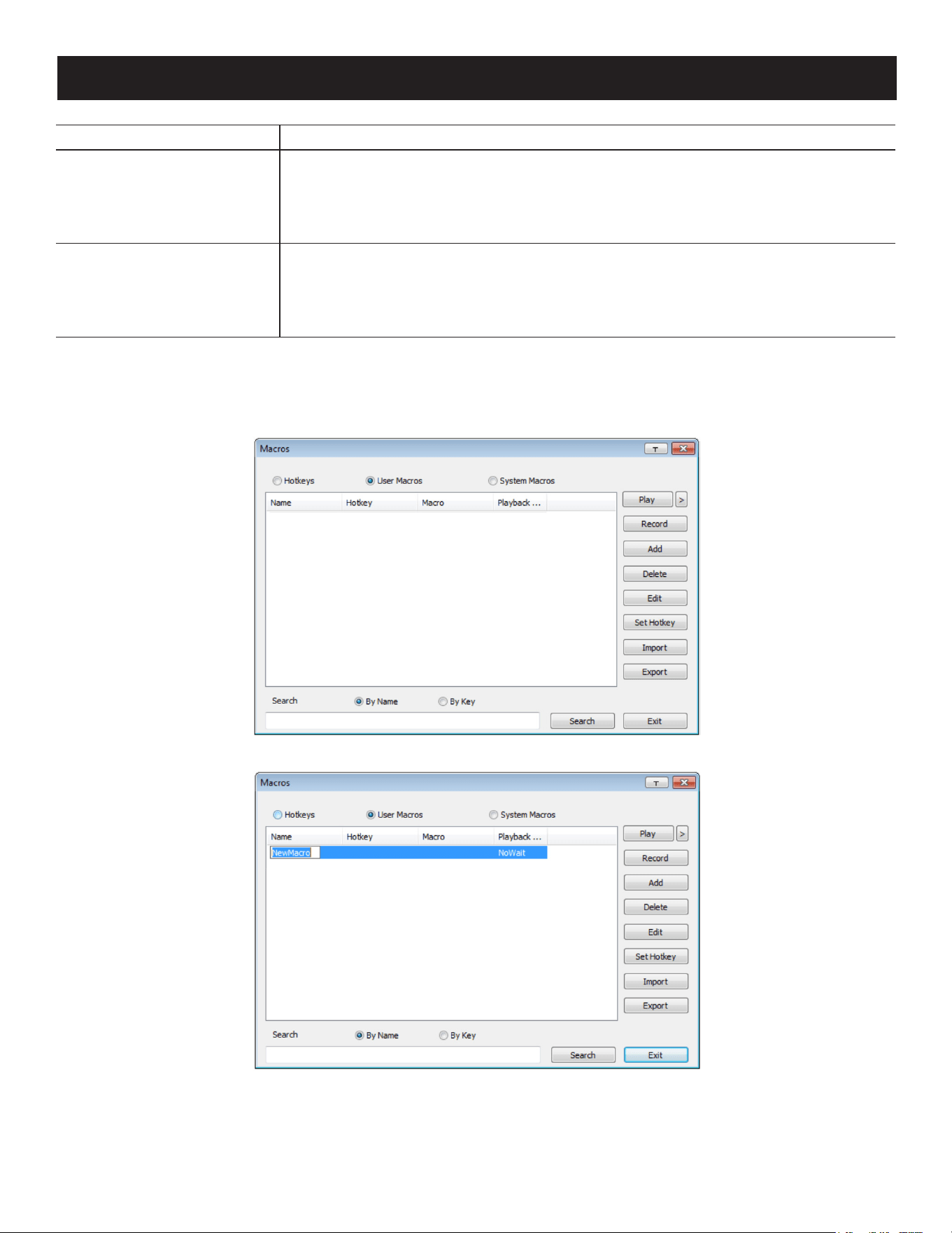
User Macros
User Macros are created to perform specific actions on the remote server. To create the macro, do the following:
1. Select User Macros, then click Add.
2. In the dialog box that opens, replace the “New Macro” text with a name of your choice for the macro:
56
7. Administration
3. Click Record.
The dialog box disappears and a small panel appears at the top left of the screen:
4. Press the keys for the macro.
• To pause macro recording, click Pause. To resume, click Pause again.
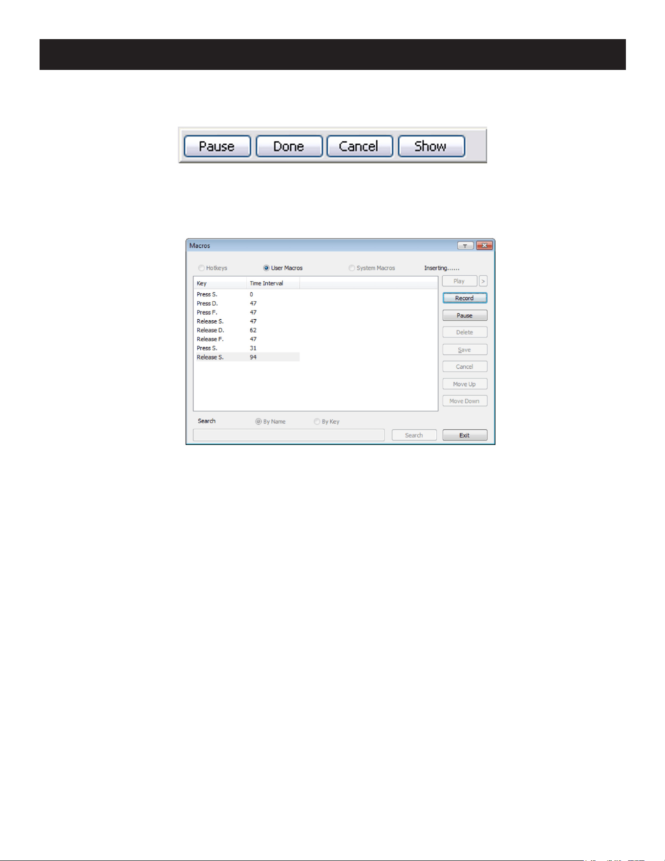
• Clicking Show opens a dialog box that lists each keystroke you make, together with the amount of time each one
takes:
Clicking Cancel cancels all keystrokes.
Once you have finished, click Stop (this is the equivalent of clicking Done in Step 5).
Notes:
• Case is not considered - typing A or a has the same effect.
• When recording the macro, the focus must be on the remote screen. It cannot be in the macro dialog box.
• Only the default keyboard characters may be used. Alternate characters cannot be used. For example, if the keyboard is Traditional
Chinese and default character is A, the alternate Chinese character obtained via keyboard switching is not recorded.
5. If you have not opened the Show dialog, click Done when you have finished recording your macro. You return to the
Macros dialog box with your macro keystrokes displayed in the Macro column:
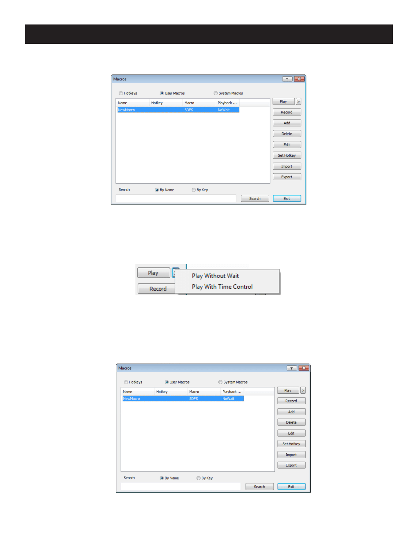
57
7. Administration
6. If you want to change any of the keystrokes, select the macro and click Edit. This will open a dialog box similar to the
one for Show. You can change the content of your keystrokes, change their order, etc.
7. Repeat the procedure for any other macros you wish to create.
After creating your macros, you can run them in any of three ways:
1. Using the hotkey (if one was assigned).
2. Opening the Macro List on the Control Panel and clicking the one you want.
3. Opening this (Macros) dialog box and clicking Play.
If you run the macro from this dialog box, you have the option of specifying how the macro runs.
• If you choose Play Without Wait, the macro runs the keystrokes one after another with no time delay between
them.
• If you choose Play with Time Control, the macro waits for the amount of time between keystrokes that you took
when you created it. Click on the arrow next to Play to make your choice.
• If you click Play without opening the list, the macro runs with the default choice (NoWait or TimeCtrl), which is
shown in the Playback column.
Note: User Macros are stored on the Local Client computer of each user. Therefore, there is no limitation on the number of macros,
size of the macro names or makeup of the hotkey combinations that invoke them.
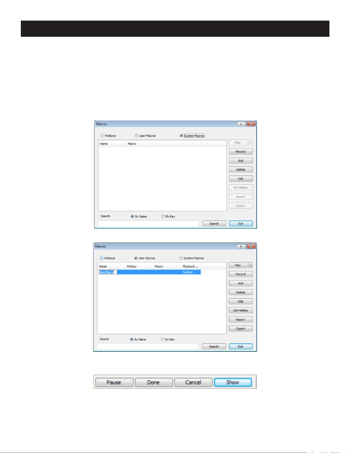
58
Search
Located at the bottom of the dialog box, the Search button lets you filter the list of macros that appear in the large
upper panel for you to play or edit. Click a radio button to choose whether you want to search by name or by key, key
in a string for the search, then click Search. All instances that match your search string will appear in the upper panel.
System Macros
System Macros are used to create exit macros for when you close a session. For example, as an added measure of
security, you can create a macro that sends the Winkey-L combination which would cause the remote server’s log in
page to open the next time the device was accessed. To create the macro:
1. Select System Macros, then click Add.
2. In the dialog box that opens, replace the “New Macro” text with a name of your choice for the macro.
3. Click Record.
The dialog box will disappear and a small panel will appear at the top left of the screen.
7. Administration
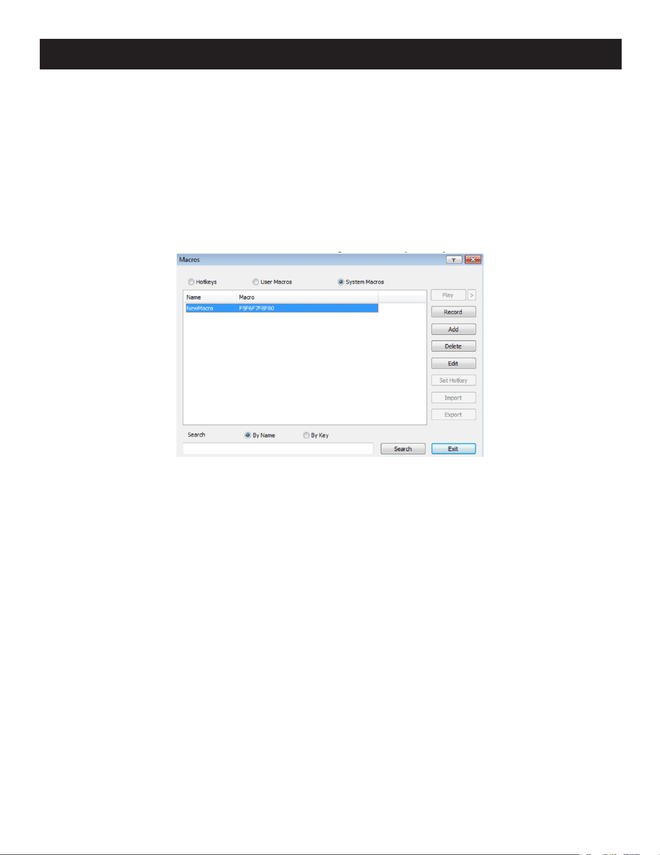
59
7. Administration
4. Press the keys for the macro.
• To pause macro recording, click Pause. To resume, click Pause again.
• Clicking Show opens a dialog box that lists each keystroke that you make, together with the amount of time each
one takes.
Notes:
• Case is not considered - typing A or a has the same effect.
• When recording the macro, the focus must be on the remote screen. It cannot be in the macro dialog box.
• Only the default keyboard characters may be used. Alternate characters cannot be used. For example, if the keyboard is Traditional
Chinese and default character is A the alternate Chinese character obtained via keyboard switching is not recorded.
5. If you have not opened the Show dialog, click Done when you have finished recording your macro. You will return to
the Macros dialog box with your system macro key presses displayed in the Macro column:
6. If you want to change any of the keystrokes, select the macro and click Edit. This will open a dialog box similar to the
one for Show. You can change the content of your keystrokes, change their order, etc.
7. Repeat the procedure for any other macros you wish to create.
Once the system macros have been created, they are available for use on a port-by-port basis. They get selected on a
port’s Port Configuration Port Properties page.
Notes:
• You can choose only one system macro per port.
• System macros are stored on the switch. Therefore, macro names may not exceed 64 Bytes and hotkey combinations may not exceed
256 Bytes (each key usually takes 3-5 Bytes).
• System macro names only support ASCII characters.
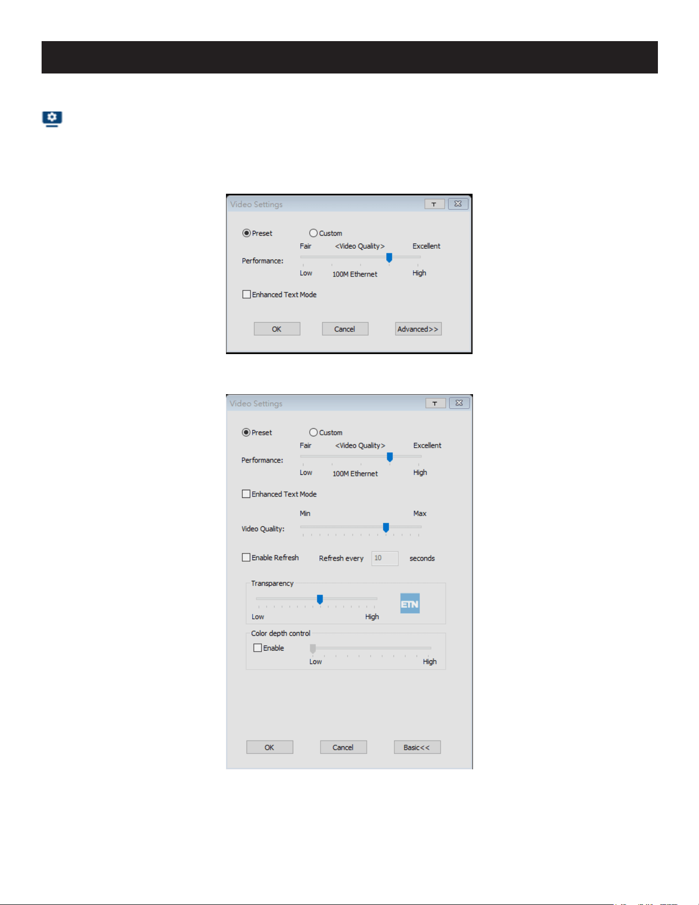
60
7. Administration
Video Settings
Clicking the Video Settings icon on the Control Panel opens the Basic Video Settings dialog box with basic settings.
The options in the basic dialog box allow you to adjust the Screen Position, set Auto-Sync and slide the
Performance bar setting. Selecting the Advanced button opens the Advanced Video Settings dialog box to provide
more detailed options including: Video Quality, Enable Refresh, Transparency and Color Depth Control.
Basic Video Settings
Advanced Video Settings

61
7. Administration
The meanings of the video adjustment options are provided in the table below:
Options Description
Preset / Custom Using the Preset and Custom buttons allow you to set and save custom video settings
and revert to default video settings.
Performance Use the slide bar to select the type of Internet connection the local client computer
uses. The switch will use that selection to automatically adjust the Video Quality
settings to optimize the quality of the video display.
Since network conditions vary, if none of the presets are working to your expectations,
you can select Advanced and use the Video Quality slider bar to adjust the settings to
suit your conditions
Video Quality Drag the slider bar to adjust the overall Video Quality. The larger the value, the clearer
the picture and the more video data goes through the network. Depending on the
network bandwidth, a high value may adversely aect response time.
Enable Refresh The KVM over IP switch can redraw the screen every 1 to 99 seconds, eliminating
unwanted artifacts from the screen. Select Enable Refresh and enter a number from
1 through 99. The KVM over IP switch will redraw the screen at the interval you specify.
This feature is disabled by default. Click to put a check mark in the box next to Enable
Refresh to enable this feature.
Notes:
• The switch starts counting the time interval when the mouse movement stops.
• Enabling this feature increases the volume of video data transmitted over the network. The lower
the number specied, the more often the video data is transmitted. Setting too low a value may
adversely aect overall operating responsiveness.
Transparency Adjusts the transparency of the toolbar that opens when the GUI hotkey ([Scroll Lock]
[Scroll Lock], for example) is invoked. Slide the bar until the display in the example
window is to your liking.
Color Depth Control This setting determines the richness of the video display by adjusting the amount of
color information.
Network Bandwidth Information for KVM Sessions
For network bandwidth management, a KVM session of a full-screen video display at 1920 x 1080 @ 60 Hz will take up
approximately 64 Mbps.
However, since the network environment of each station/session varies, the aforementioned information proposes what
is ideal but does not warrant the smoothness/quality for each session.
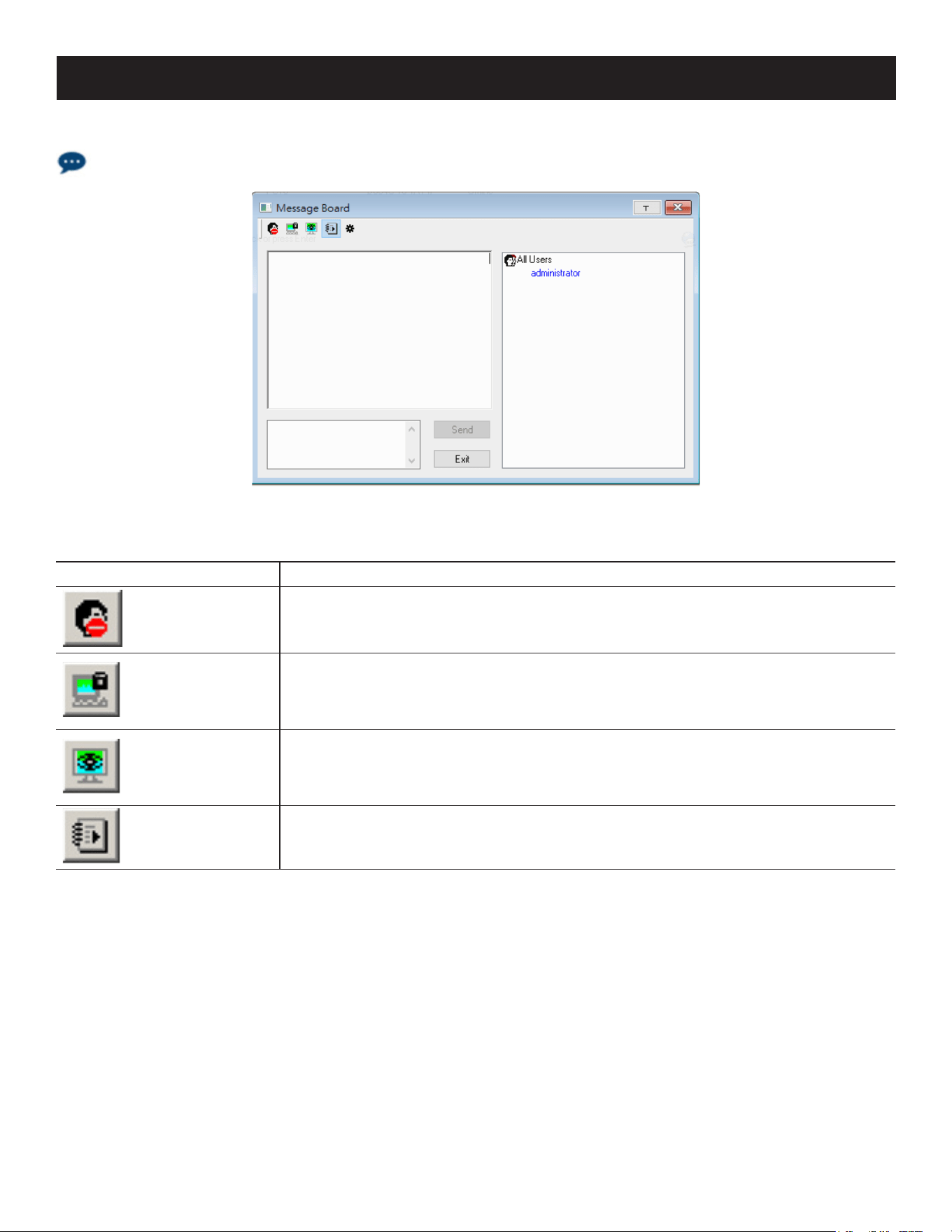
62
7. Administration
The Message Board
The B064C-16-1X1-IP supports multiple user logins, which may cause access conflicts. To alleviate the problem, a
message board is provided to allow users to communicate with one other:
Button Bar
The buttons on the Button Bar are toggles.
Button Action
Enable/Disable Chat: When disabled, messages posted to the board are not
displayed. The button is shadowed when Chat is disabled. The icon displays next to
the user's name in the User List panel when the user has disabled Chat.
Occupy/Release Keyboard/Video/Mouse: When you Occupy the KVM, other users
cannot see the video, nor input keyboard or mouse data. The button is shadowed
when the KVM is occupied. The icon displays next to the user's name in the User List
panel when the user has occupied the KVM.
Occupy/Release Keyboard/Mouse: When you Occupy the KM, other users can see
the video, but cannot input keyboard or mouse data. The button is shadowed when
the KM is occupied. The icon displays next to the user’s name in the User List panel
when the user has occupied the KM.
Show/Hide User List: When you hide the User List, the User List panel closes. The
button is shadowed when the User List is open.
Message Display Panel
Messages that users post to the board - as well as system messages - display in this panel. If you disable Chat, however,
messages that get posted to the board won’t appear.
Message Display Panel
Messages that users post to the board (as well as system messages) display in this panel. If you disable Chat, messages
that get posted to the board will not appear.
Compose Panel
Key in the messages that you want to post to the board in this panel. Click Send, or press [Enter] to post the message
to the board.
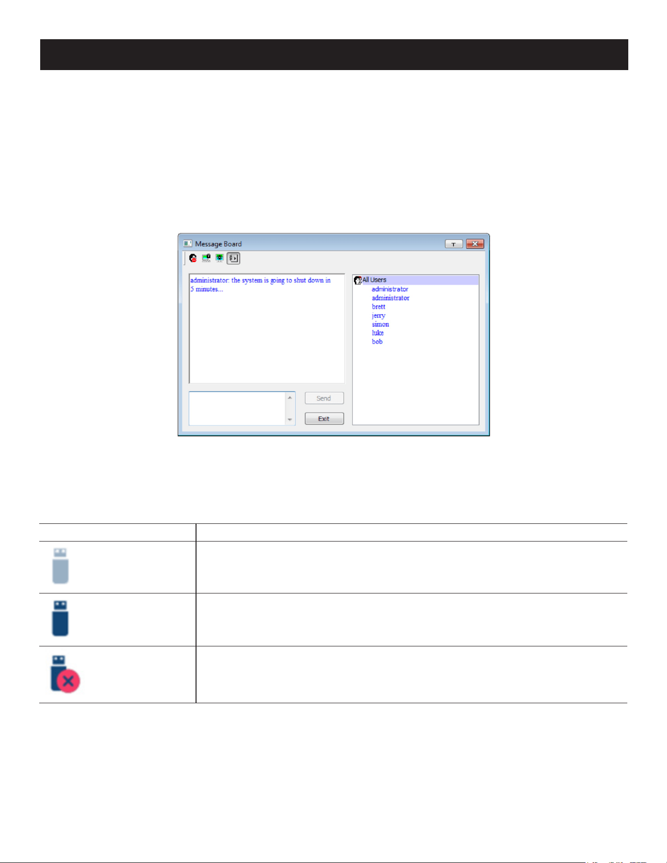
63
7. Administration
User List Panel
The names of all the logged in users are listed in this panel.
• Your name appears in blue and other users’ names appear in black.
• By default, messages are posted to all users. To post a message to an individual user, select the user’s name before
sending your message.
• If a user’s name is selected and you want to post a message to all users, select All Users before sending your
message.
• If a user has disabled Chat, its icon displays before the user’s name to indicate so.
• If a user has occupied the KVM or the KM, its icon displays before the user’s name to indicate as such.
Virtual Media
The Virtual Media feature allows a drive, folder, image file, removable disk or smart card reader on a user’s system to
appear and act as if it were installed on the remote server.
The Virtual Media icon changes depending on the status of the virtual media function, as shown in the table below:
Icon Function
The icon displays in gray to indicate the virtual media function is disabled or not
available.
The icon displays in blue to indicate that the virtual media function is available. Click
the icon to open the virtual media dialog box.
The icon displays in blue with a red X to indicate a virtual media device has been
mounted on the remote server. Click the icon to unmount all redirected devices.
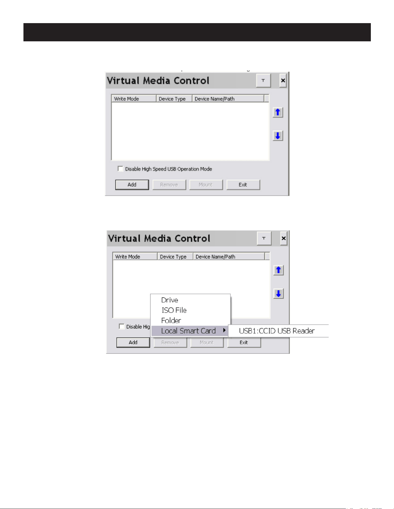
64
7. Administration
Mounting Virtual Media
1. Click the Virtual Media icon to open the Virtual Media dialog box.
Note: The T button at the top right opens a slider to adjust the transparency of the dialog box. After making your adjustment, click
anywhere in the dialog box to dismiss the slider.
2. Click Add; then select the media source.
Depending on your selection, additional dialog boxes appear to select the drive, ISO file, folder, or removable disk you
desire. See 8.9 Virtual Media Support for a list of supported virtual media types and details about mounting them.
3. If your device only supports full-speed USB, put a check in the Disable High Speed USB Operation Mode checkbox.
4. To add additional media sources, click Add and select the source as many times as you require. Up to three virtual
media choices can be mounted. The top three in the list are the ones that are selected. Virtual Media and Smart
Card readers can be mounted at the same time. To rearrange the selection order, highlight the device you want to
move, then click the Up or Down arrow button to promote or demote it in the list.
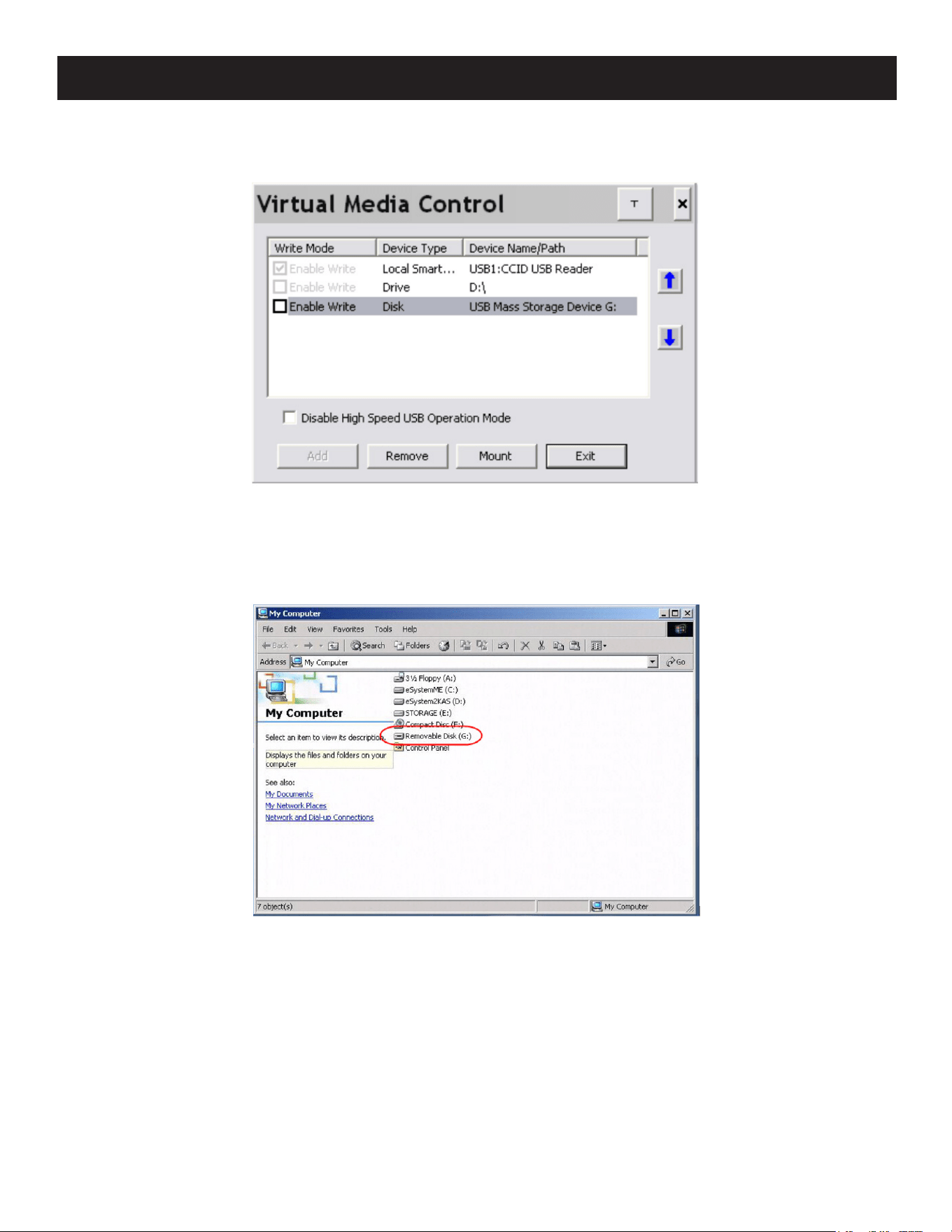
65
7. Administration
5. Read refers to the redirected device being able to send data to the remote server and Write refers to the redirected
device being able to have data from the remote server written to it. For the redirected device to be writable as well
as readable, click to put a check in the Enable Write checkbox:
Note: If a redirected device cannot be written to, it will appear in gray.
6. To remove an entry from the list, select it and click Remove.
7. Once you have made your media source selections, click Mount. The dialog box will close. The virtual media devices
you have selected are redirected to the remote server, where they will appear as drives, files, folders, etc. on the
remote server’s file system.
Once mounted, you can use the virtual media as if they really existed on the remote server; drag and drop files to/from,
open files on the remote server for editing and save them to the redirected media, etc.
Files saved to the redirected media will be saved on your local client computer’s storage and files you drag from the
redirected media will come from your local client computer’s storage.
8. To end the redirection, open the Control Panel and click on the Virtual Media icon. All mounted devices are
automatically unmounted.
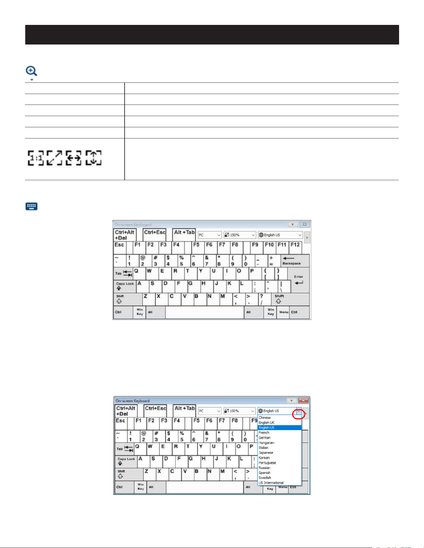
66
7. Administration
Zoom
The Zoom icon controls the zoom factor for the remote view window. Settings are as follows:
Setting Description
100% Sizes and displays the remote view window at 100%.
75% Sizes and displays the remote view window at 75%.
50% Sizes and displays the remote view window at 50%
25% Sizes and displays the remote view window at 25%
Sizes and displays the remote view window at 100%. The dierence between this
setting and the 100% setting is that when the remote view window is resized its
contents do not resize. Instead, they remain at their previous size. To see any objects
that are outside of the viewing area, move the mouse to the window edge for the
screen to scroll.
On-Screen Keyboard
The KVM switch supports an on-screen keyboard available in multiple languages and with all the standard keys
for each supported language. Click this icon to pop up the on-screen keyboard:
One of the major advantages of the on-screen keyboard is that if the keyboard languages of the remote and local
systems are not the same, you do not need to change the configuration settings for either system. Simply access the
on-screen keyboard, select the language used by the server you are accessing and use the on-screen keyboard to
communicate with it.
Note: You must use your mouse to click on the keys. You cannot use your actual keyboard.
Changing Languages
1. Click the down arrow next to the currently selected language to view a drop-down selection of the language list.
2. Select the new language from the list.
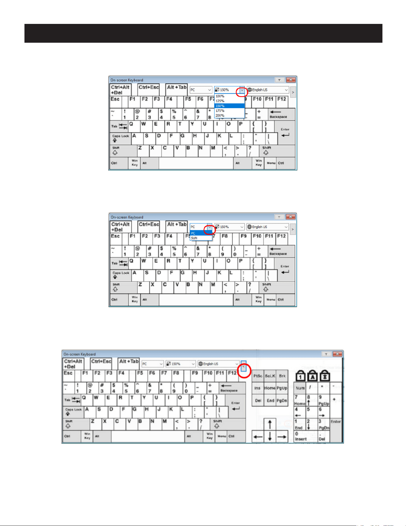
67
7. Administration
Resizing the Keyboard
1. Click the down arrow next to the currently selected keyboard size, to drop down the sizing list.
Selecting Platforms
The on-screen keyboard supports the Sun and PC platforms. To select the platform:
1. Click the down arrow next to the currently selected platform for drop-down of the platform list to appear.
2. Select the new platform from the list.
Expanded Keyboard
To display/hide the expanded keyboard keys, click the arrow to the right of the language list arrow.
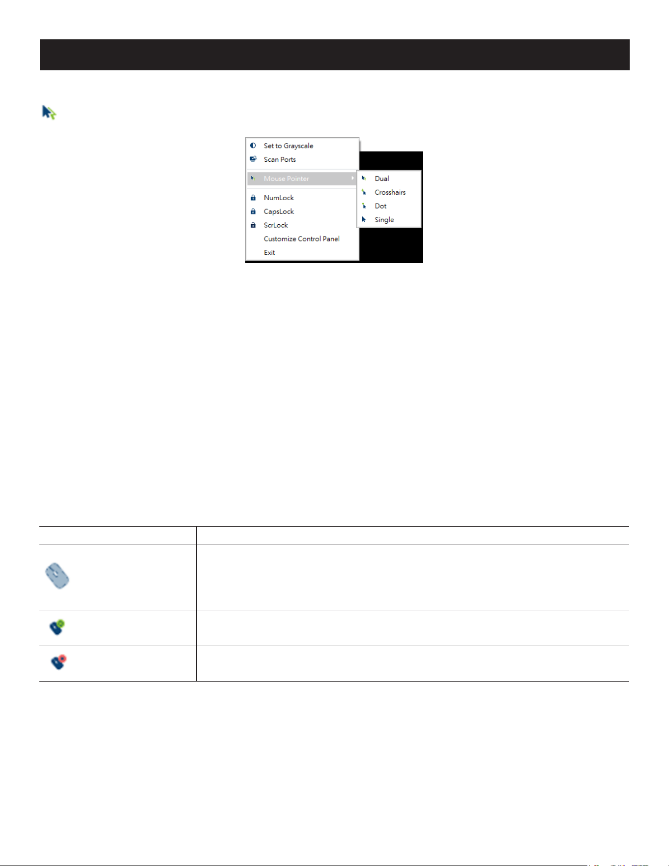
68
7. Administration
Mouse Pointer Type
KVM over IP switches offer several mouse pointer options when working in the remote display. Click this icon to
select from the available choices:
Notes:
• Before accessing a port it is important to know the Single option is not available. Once the port is accessed, all four pointers are
available.
• The Dot pointer is not available with the Java Applet Viewer or the Java Client AP.
• Selecting the Dot pointer has the same effect as the Toggle mouse display hotkey function.
• The icon on the Control Panel changes to match your choice.
Mouse DynaSync Mode
Synchronization of the local and remote mouse pointers is accomplished automatically or manually.
Automatic Mouse Synchronization (DynaSync)
Mouse DynaSync provides automatic locked-in synching of the remote and local mouse pointers, eliminating the need to
constantly resync the two movements.
Notes:
• This feature is only available for Windows and Mac systems (G4 or later) whose adapter attribute OS setting is configured for Win or Mac.
• All other configurations must use manual mouse synchronization.
The icon on the Control Panel indicates the synchronization mode status as follows:
Icon Function
This icon displays in gray to indicate that Mouse DynaSync is not available and you
must use manual synching procedures. This is the default setting for all KVM Adapters,
which are connected to the switch with one of the following Adapter Cables: B055-
001-UDV, B055-001-UHD, B055-001-UDP, B055-001-USB, B055-001-USB-V2, B055-
001-USB-VA, B055-001-UV2CAC.
The green check mark on this icon indicates Mouse DynaSync is available and enabled.
This is the default setting when Mouse DynaSync is available.
The red X on this icon indicates Mouse DynaSync is available but is not enabled.
When Mouse DynaSync is available, clicking the icon toggles its status between enabled and disabled. If you choose to
disable Mouse DynaSync mode, you must use the manual synching procedures described in the Manual Mouse
Synchronization section.
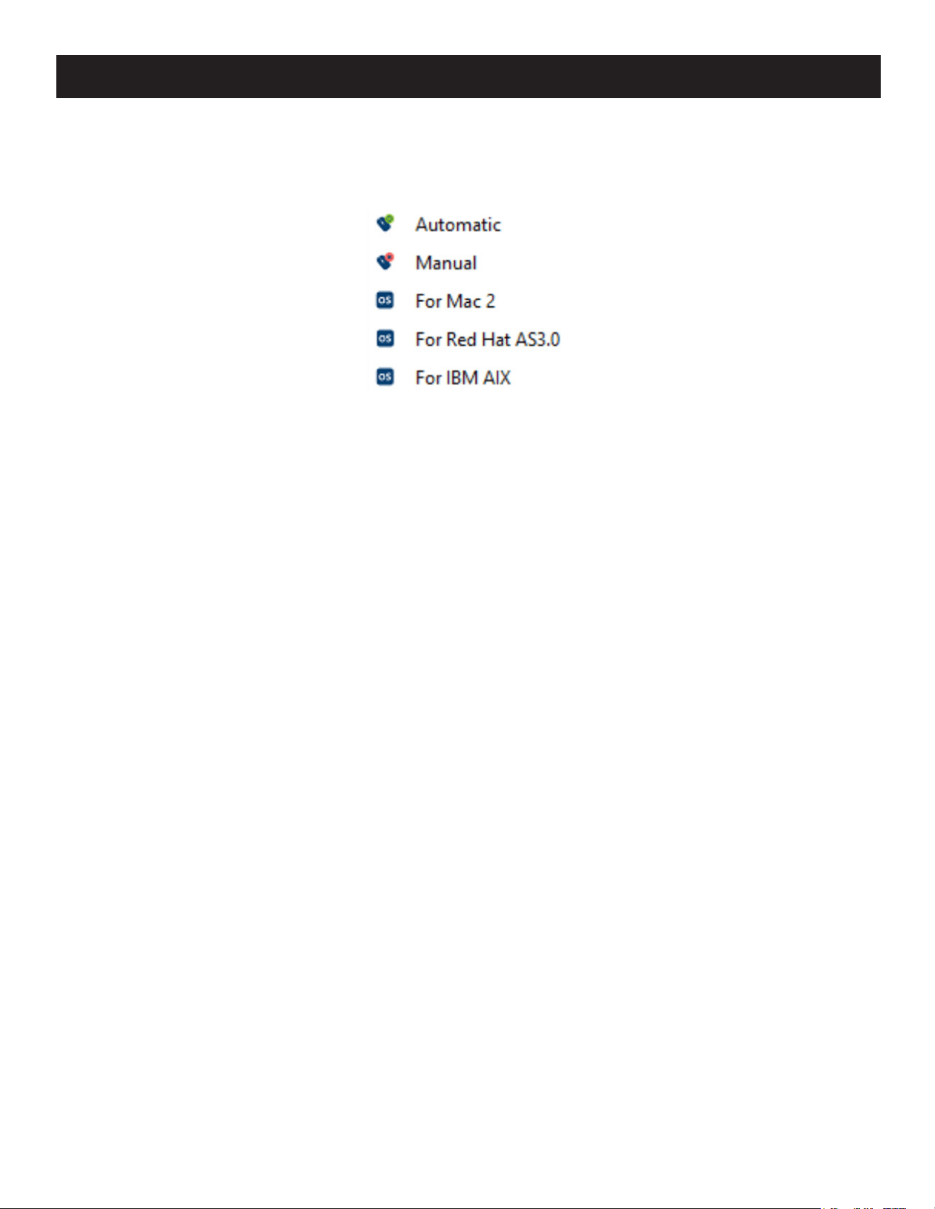
69
7. Administration
Mac and Linux Considerations
• For Mac OS versions 10.4.11 or later, there is a second DynaSync setting to choose from: if the default Mouse
DynaSync result is not satisfactory, try the Mac 2 setting. To select Mac 2, right-click in the text area of the Control
Panel and select Mouse Sync Mode Automatic for Mac 2:
• Linux does not support DynaSync Mode, but there is a setting on the Mouse Sync Mode menu for Redhat AS3.0
systems. If you are using a USB Adapter Cable with an AS3.0 system and the default mouse synchronization is not
satisfactory, you can try the Redhat AS3.0 setting. In either case, you must perform the manual mouse
synchronization procedures described in the next section.
Manual Mouse Synchronization
If the local mouse pointer becomes out of sync with the remote system’s mouse pointer, there are several methods to
return them to sync:
1. Perform a video and mouse auto sync by clicking the Video Settings icon on the Control Panel.
2. Perform an Auto Sync with the Video Adjustment function.
3. Invoke the Adjust Mouse function with the Adjust Mouse hotkeys.
4. Move the pointer into all four corners of the screen (in any order).
5. Drag the Control Panel to a different position on the screen.
6. Set the mouse speed and acceleration for each problematic server attached to the switch. See 8.6.1 Additional
Mouse Synchronization Procedures for details.
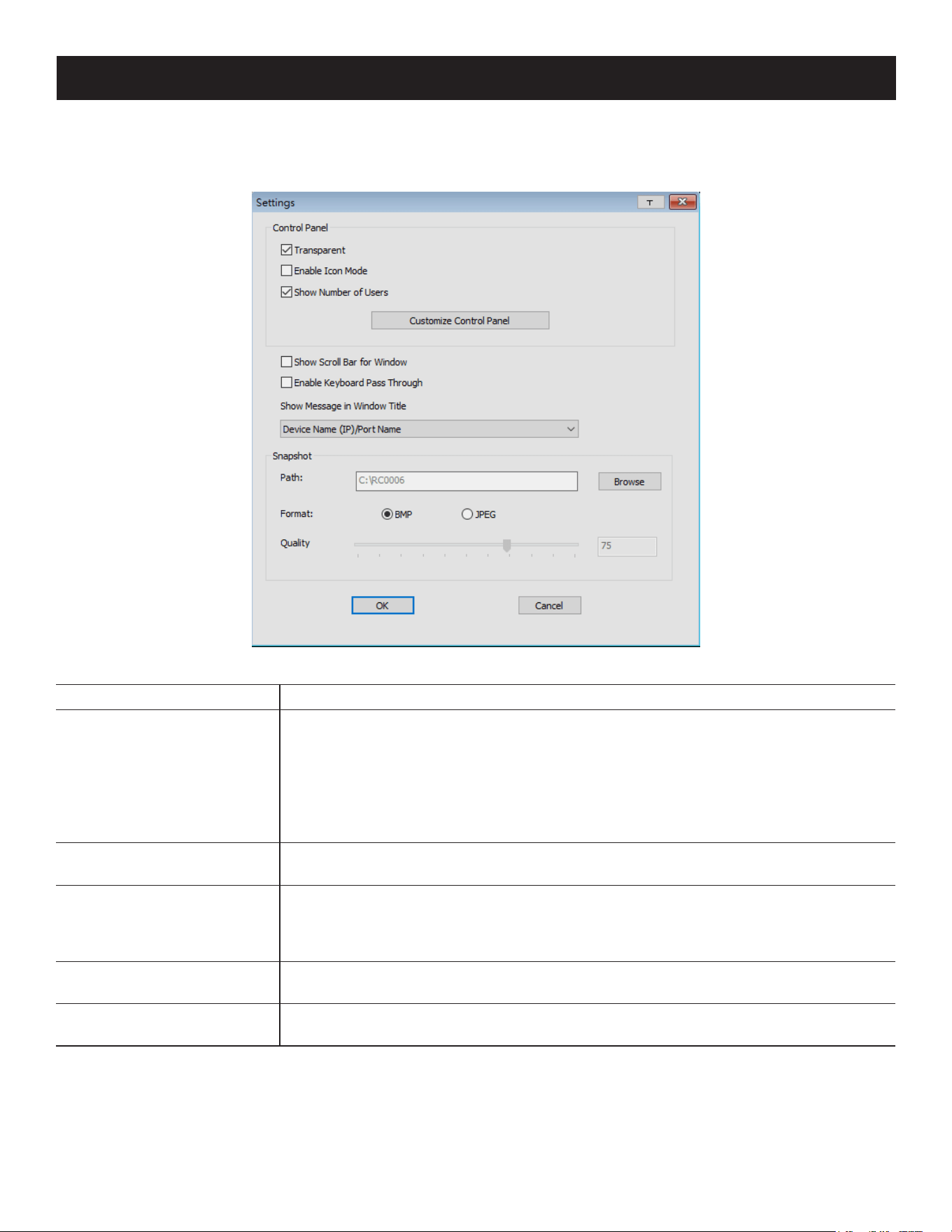
70
7. Administration
Control Panel Configuration
Clicking the Control Panel icon opens a dialog box that allows you to configure the items that appear on the Control
Panel as well as its graphical settings:
The organization of the dialog box is described in the table below:
Item Description
Control Panel
• Enabling Transparent makes the Control Panel semi-transparent so you can see
through it to the display underneath.
• Enabling Enable Icon causes the Control Panel to display as an icon until you mouse
over it. When you mouse over the icon, the full panel comes up.
• Enabling Show Number of Users shows the number of the bus you are on, as well as
the total number of users on the bus. This displays on the bottom row center of the
Control Panel as: Bus No./ Total Users.
Customize Control Panel
Allows you to select which icons display in the Control Panel. Check the ones you want
to view and uncheck the ones you do not want to view.
Show Scroll Bar for Window
In cases where the remote screen display is larger than your monitor, you can choose
how to scroll to the areas that are o-screen. When this is enabled, the show bar for
windows allows scroll bars to appear around the screen borders that you can use to
scroll to the o-screen areas.
Enable Keyboard Pass
Through
When this is enabled, the Alt-Tab key press is passed to the remote server and aects
that server. If it is not enabled, Alt-Tab acts on your local client computer.
Show Message in Window
Title
Select to show message such as port name, device name, resolution, frame rate and
bandwidth in the window title.
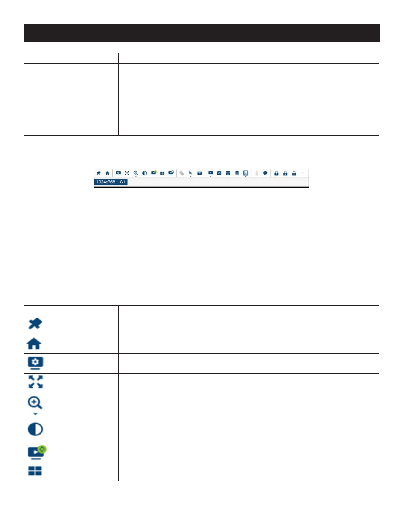
71
7. Administration
Item Description
Snapshot
These settings allow the user to congure B064C-16-1X1-IP’s screen-capture
parameters:
• Path lets you select a directory that the captured screens automatically get saved to.
Click Browse and navigate to the directory of your choice, then click OK. If you do
not specify a directory here, the snapshot is saved to your desktop.
• Click a radio button to choose whether you want the captured screen to be saved as
a BMP or a JPEG (JPG) le.
• If you choose JPEG, you can select the quality of the captured le with the slider bar.
The higher the quality, the better looking the image, but the larger the le size.
Java Control Panel
The Java Client AP Control Panel is similar to the one used by the WinClient:
The major differences between them are:
• In the Macros dialog box, Toggle Mouse Display is not available.
• The Dot mouse pointer type is not available.
• In the Message Board, there is no Show/Hide button to show or hide the user list. This function is achieved by clicking
the arrows at the top of the bar that separates the User List panel from the Main panel.
• The Control Panel Lock LED icons are not in sync with your keyboard.
o When you first connect, the LED display may not be accurate. To be sure, click on the LED icons to set them.
• In Control Panel Configuration, the BMP Snapshot format has been replaced by PNG.
To access to the Customize Control Panel, right-click in the text row area to open a menu-style version of the toolbar.
Doing this also allows you to select options for the Screen Mode, Zoom, Mouse Pointer and Macro List.
JavaClient Control Panel Functions
Icon Function
This is a toggle. Click to make the Control Panel persistent (e.g., it always displays on
top of other screen elements). Click again to have it display normally.
Under an accessed port, click to recall the GUI.
Click to open the Video Options dialog box. Right-click to perform a quick Auto Sync.
Toggles the display between Full Screen Mode and Windowed Mode.
Click to zoom the remote display window.
Note: This feature is only available in windowed mode (Full Screen Mode is o).
Click to toggle the remote display between color and grayscale views.
Click to perform a video and mouse auto sync operation. It is the same as clicking the
Auto sync button in the Video Options dialog box.
Under an accessed port, click to invoke Panel Array Mode
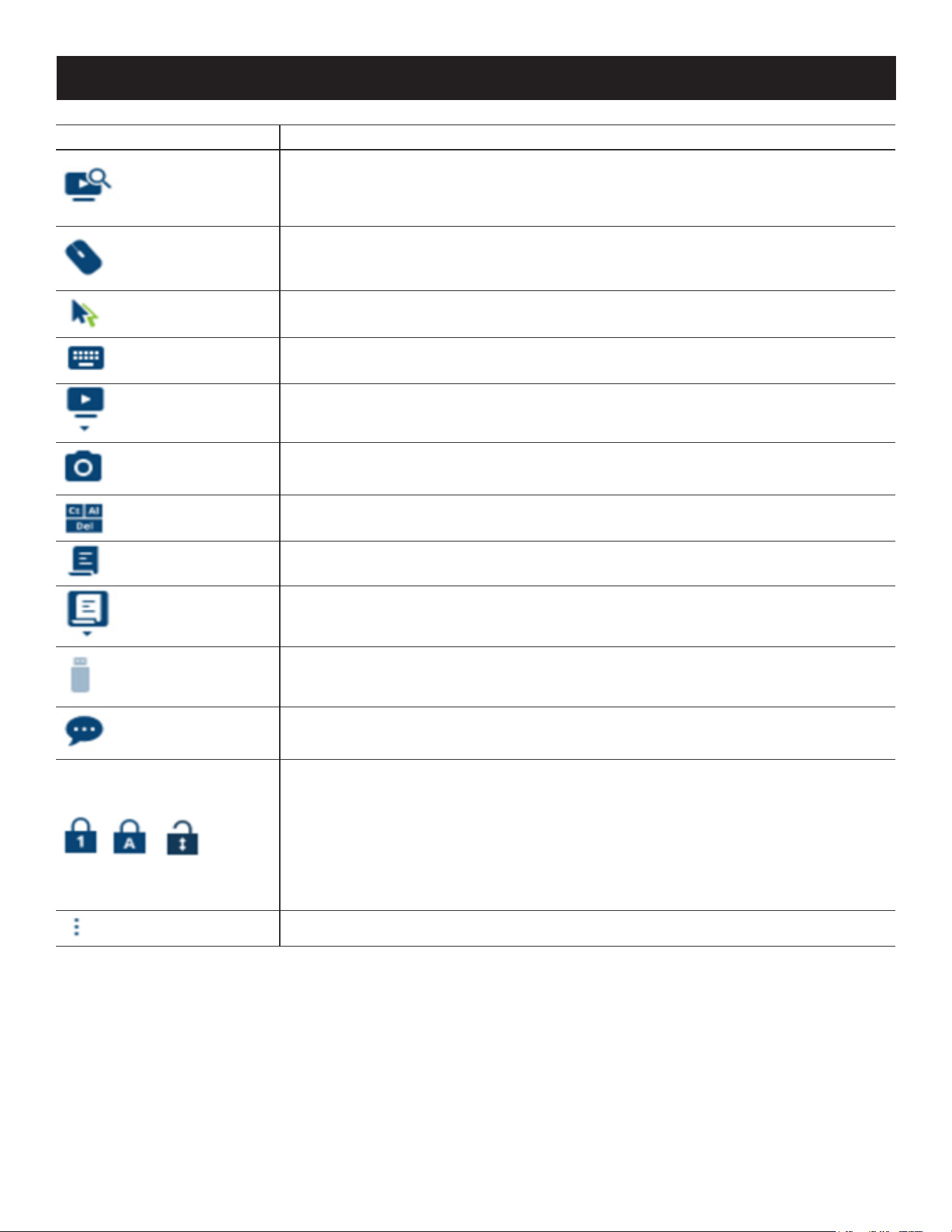
72
7. Administration
Icon Function
Under an accessed port, click to begin Auto Scan Mode. The KVM over IP switch
automatically switches among the ports that were selected for Auto Scanning with the
Filter function. This allows you to monitor their activity without having to switch among
them manually.
Click to toggle Automatic or Manual mouse sync.
• When the selection is Automatic, a green √ appears on the icon.
• When the selection is Manual, a red X appears on the icon.
Click to select the mouse pointer type.
Note: This icon changes depending on which mouse pointer type is selected.
Click to open the on-screen keyboard.
Click to select the port you wish to connect to.
Click to take a snapshot (screen capture) of the remote display.
Click to send a Ctrl+Alt+Del signal to the remote system.
Click to open the Macros dialog box.
Click to display a dropdown list of User macros to access and run macros more
conveniently than using the Macros dialog box.
Click to open the Virtual Media dialog box. The icon changes depending on the status
of the virtual media function.
Note: This icon displays in gray when the function is disabled or not available.
Click to open the Message Board.
These icons show the Num Lock, Caps Lock, and Scroll Lock status of the remote
computer.
• When the lock state is On, the LED illuminates orange and the lock hasp is closed.
• When the lock state is O, the LED illuminates blue and the lock hasp is open.
Click on the icon to toggle the status.
Note: These icons and your local keyboard icons are in sync. Clicking an icon will cause the
corresponding LED on your keyboard to change accordingly. Similarly, pressing a Lock key on your
keyboard will cause the icon’s color to change accordingly.
Click to open more control panel functions.
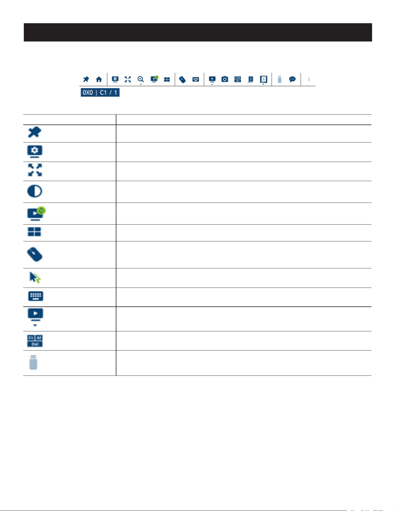
73
7. Administration
WebClient Control Panel
The WebClient Viewer is similar to the one used by the WinClient but with fewer functions.
The Control Panel functions are described in the table below:
Icon Function
This is a toggle. Click to make the Control Panel persistent (e.g., it always displays on
top of other screen elements). Click again to have it display normally.
Click to open the Video Options dialog box. Right-click to perform a quick Auto Sync.
Toggles the display between Full Screen Mode and Windowed Mode.
Click to toggle the remote display between color and grayscale views.
Click to perform a video and mouse auto sync operation. It is the same as clicking the
Auto sync button in the Video Options dialog box.
Under an accessed port, click to invoke Panel Array Mode.
Click to toggle Automatic or Manual mouse sync.
• When the selection is Automatic, a green √ appears on the icon.
• When the selection is Manual, a red X appears on the icon.
Click to select the mouse pointer type.
Note: This icon changes depending on which mouse pointer type is selected.
Click to open the on-screen keyboard.
Click to select the port you wish to connect to.
Click to send a Ctrl+Alt+Del signal to the remote system.
Click to open the Virtual Media dialog box. The icon changes depending on the status
of the virtual media function.
Note: This icon displays in gray when the function is disabled or not available.
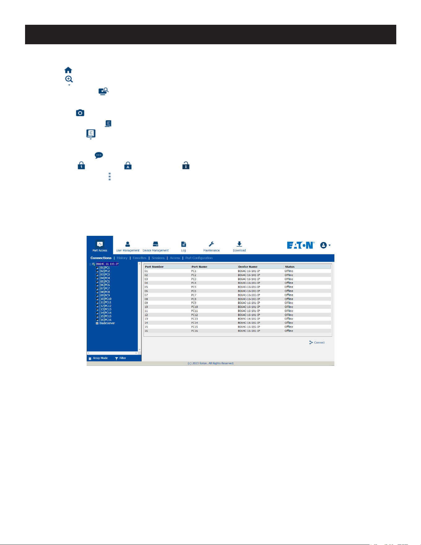
74
7. Administration
The major differences between the WinClient and WebClient are:
• The Recall is not available.
• The Zoom is not available.
• The Auto Scan Mode is not available.
• The Dot mouse pointer type is not available.
• The Snapshot is not available.
• The Macros Dialog Box is not available.
• The User Macros is not available.
• In Virtual Media, only ISO and Folder are supported.
• The Message Board is not available.
• The Num Lock , Caps Lock and Scroll Lock are not available.
• The More Control Panel is not available.
7.5 Port Access
When you log in to the switch, the Port Access page opens with the B064C-16-1X1-IP’s KVM Connections page displayed.
Browser GUI
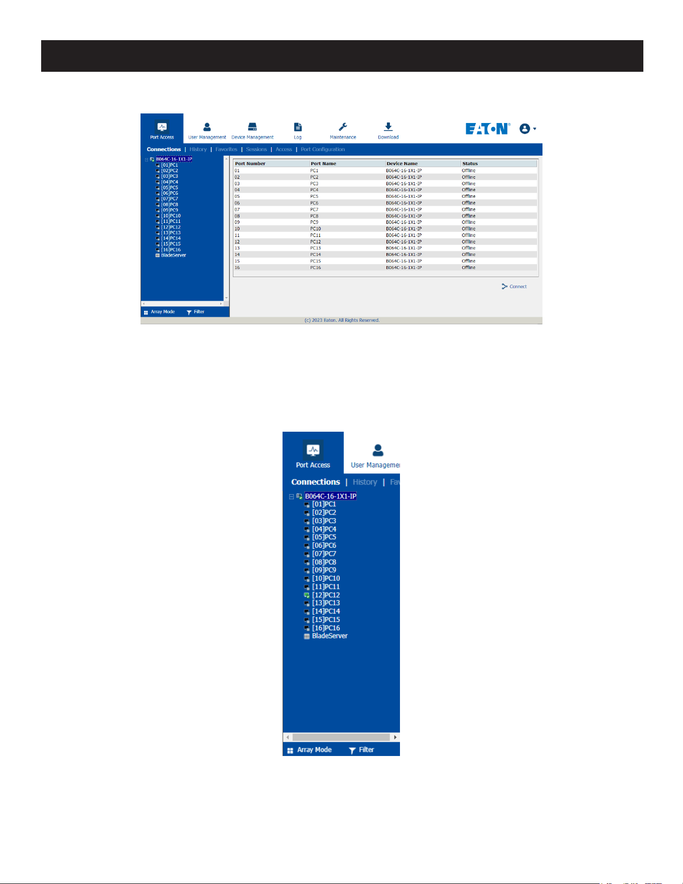
75
7. Administration
AP GUI
The Connections page is organized into several main areas. All devices and ports that a user are permitted to access
are listed in the Sidebar at the left of the page. After selecting a device or port in the Sidebar, clicking entries on the
menu bar (Browser GUI) or tab bar (AP GUI) opens information and configuration pages related to the item selected in
the Sidebar.
7.5.1 Sidebar
All KVM switches are listed in a tree structure in the Sidebar at the left of the screen:
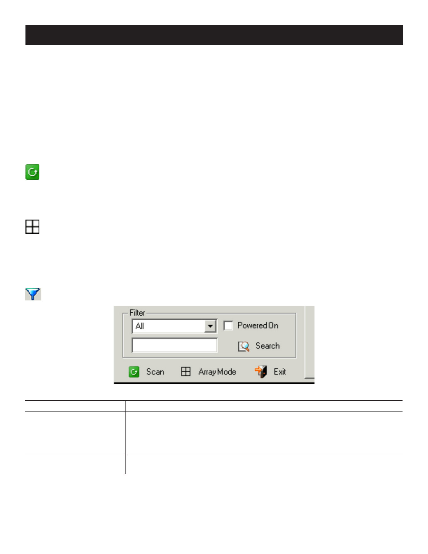
76
7. Administration
Sidebar Tree Structure
• Users are only allowed to see the devices and ports they have access permission for.
• Ports and chained station devices can be nested under their first station devices.
Click the + in front of a device to expand the tree and see the ports nested underneath it. Click the - to collapse the
tree and hide the nested ports.
• A port’s ID number is displayed in brackets next to its icon.
• Switches and ports will have their monitor screen icons in green; gray monitor screens are for devices and ports that
are offline.
• To access and operate a port, double-click its icon.
Scan
Scan is found at the bottom of the AP GUI Sidebar. It automatically switches among all the ports that are visible in
the Sidebar at regular intervals so that their activity can be monitored automatically.
Note: This item does not appear at the bottom of the Sidebar in the Browser version. In that version, you must invoke it from the port’s
Toolbar.
Array
Array is found at the bottom of the Browser and AP GUI Sidebar. It represents another way of monitoring port
activity. Under this function, your screen is divided into a grid of panels with each panel showing the video display
of a particular port. Only ports that are visible in the Sidebar and that are online are displayed - all other ports are
blank.
Note: This item does not appear at the bottom of the Sidebar in the Browser version. In that version, you must invoke it from the port’s
Toolbar.
Filter
Filter allows you to control the number and type of ports that display in the Sidebar, as well as which ports get
scanned when Auto Scan and Array Modes are invoked.
The meanings of the choices are explained in the following table:
Choices Explanation
All
This is the default view. With no other lter options selected, all the ports that are
accessible to the user are listed in the Sidebar.
If any Favorites have been specied, you can drop down the list box and select
Favorites instead of All. If you select Favorites, only the items you have selected as
Favorites display in the tree.
Powered On
If you enable Powered On (by putting a check in the checkbox), only the ports that
have their attached devices powered on display in the tree.
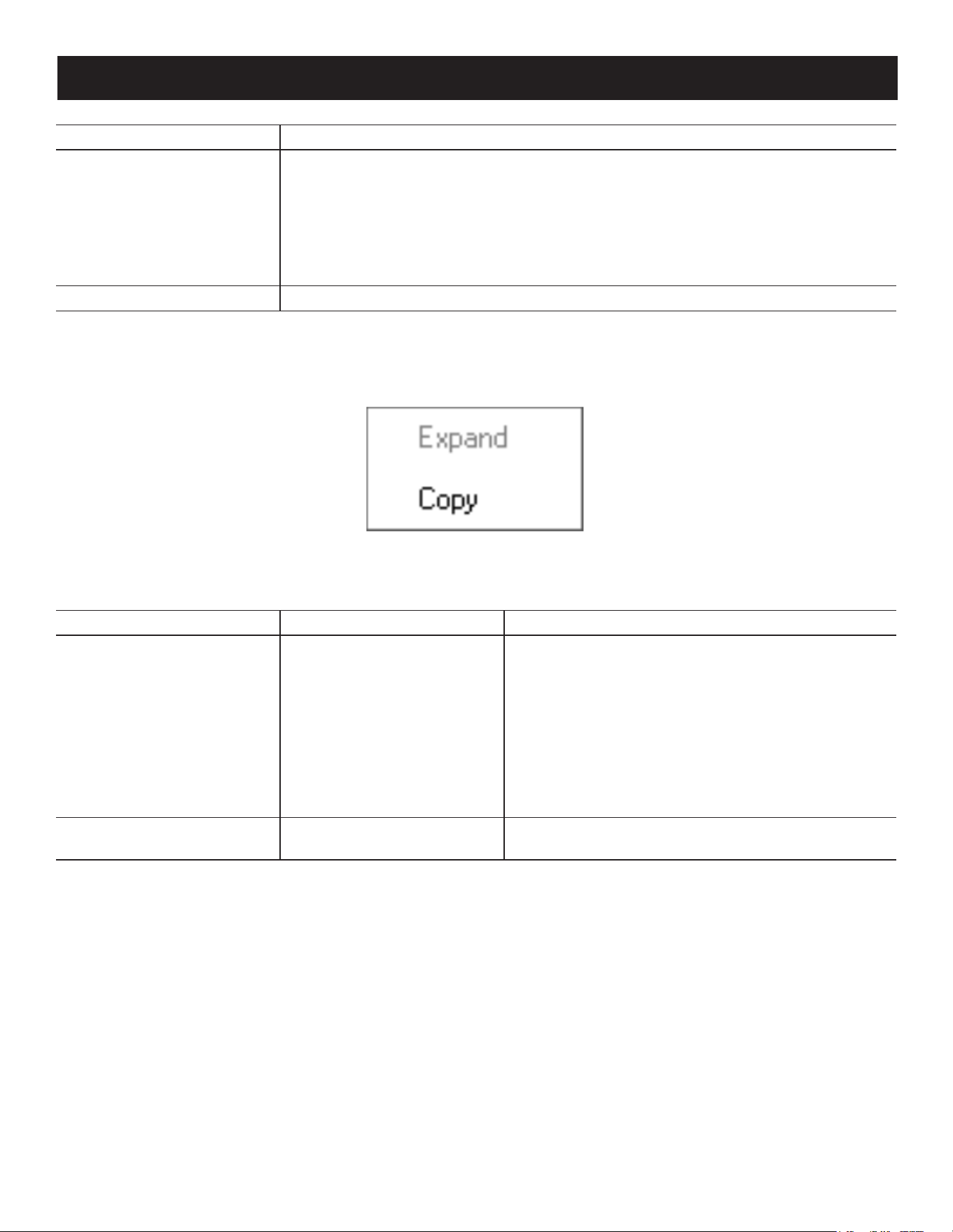
77
7. Administration
Choices Explanation
Search
If you key in a search string and click Search, only port names that match the search
string display in the tree. Wildcards (? for single characters; * for multiple characters)
and the keyword “or” are supported, so that more than one port can show up in the
list.
For example:
1. If you key in Web*, both Web Server 1 and Web Server 2 show up in the list.
2. If you key in W*1 or M*2, both Web Server 1 and Mail Server 2 show up in the list.
Exit Clicking Exit closes the lter dialog.
Sidebar Utilities
The AP GUI version Port Access Connections page provides a convenient method to work with the Sidebar tree. When
you right-click an item, a list with options pops up:
Note: The screenshot shows an example of just one of the pop-ups that can appear. The items that appear in the pop-up depend on
whether you are logged in remotely or from a Local Console, what your user type is and whether you selected a switch or a port.
The following table lists the possible items that may appear:
Item User Type Explanation
Expand/ Collapse Administrator
• If the device’s ports are nested (not displayed), the
dialog box entry is Expand. Click Expand to display
the nested ports.
• If the device’s ports are displayed, the dialog box
entry is Collapse. Click Collapse to nest the ports.
Notes:
• This item only appears for switches or for ports that have
cascaded station devices connected to them.
• This has the same eect as clicking the + or - in the tree
structure.
Copy Administrator
This item is only available for ports. After selecting
Copy, you can paste the port into the favorites page.
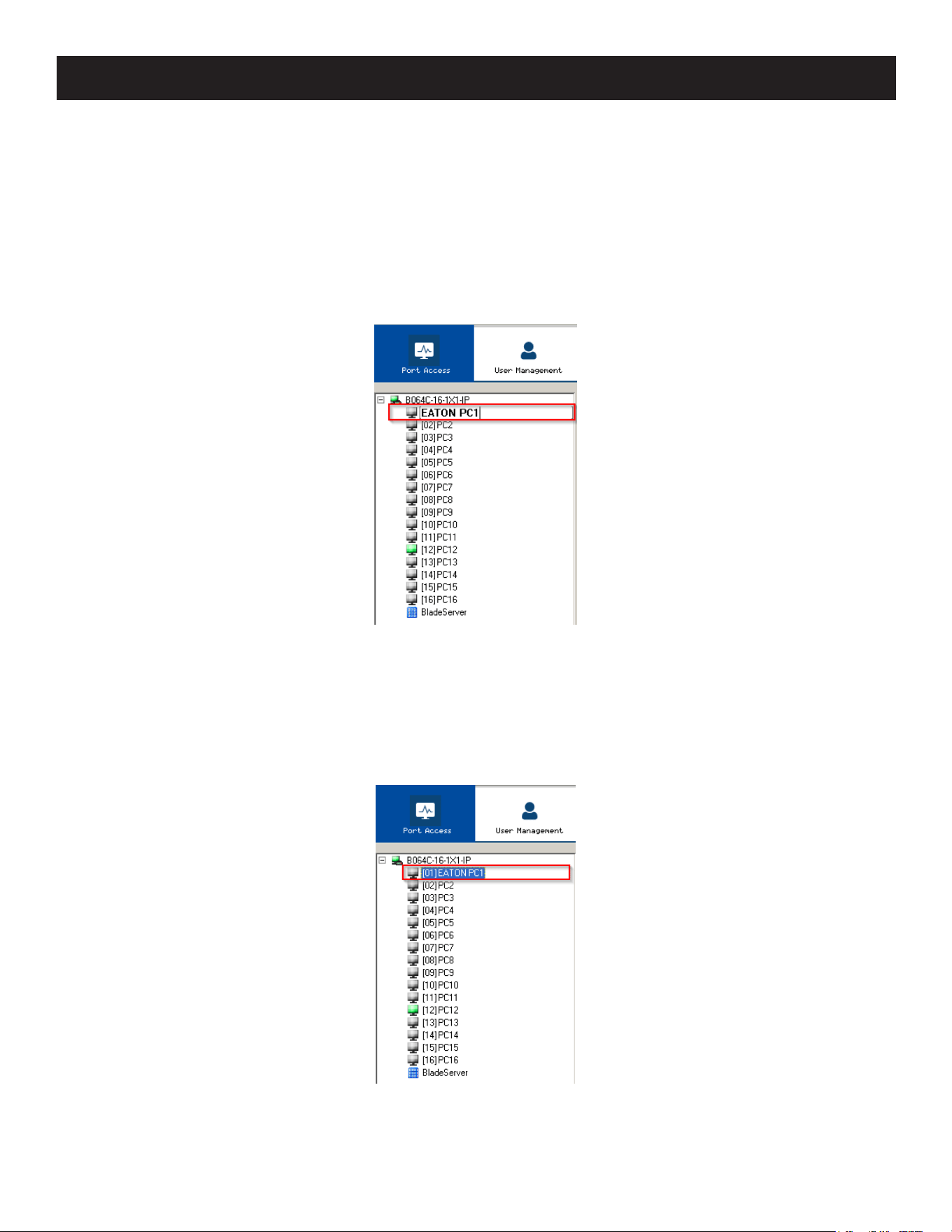
78
7. Administration
Port/Outlet Naming
For convenience – especially in large installations with many devices, ports – administrators and users with port
configuration permission can give each port or outlet a name. To assign, modify or delete a name, do the following:
1. Click once on the item you want to edit, wait a moment, then click again.
Notes:
• This is not a double-click, as it involves two separate clicks. A double-click will switch you to the device attached to the port.
• In the AP GUI version you can right-click on the port you want to edit, then select Rename in the popup box that appears or you can
highlight the port and press F2.
After a second or two, the field changes to provide a text input box:
2. Key in a name for the item (or change/delete a previous one).
• You can use any combination of letters, numbers and symbols on the typewriter keys of keyboards with PC US
English layout. In this case, the maximum number of characters allowed is 20.
• You can also activate your local IME to input non-English characters. For languages that use 2-byte encoding, the
maximum number of characters allowed is 9.
3. When you have finished editing the name, press [Enter] or click anywhere outside of the input box to complete the
operation.
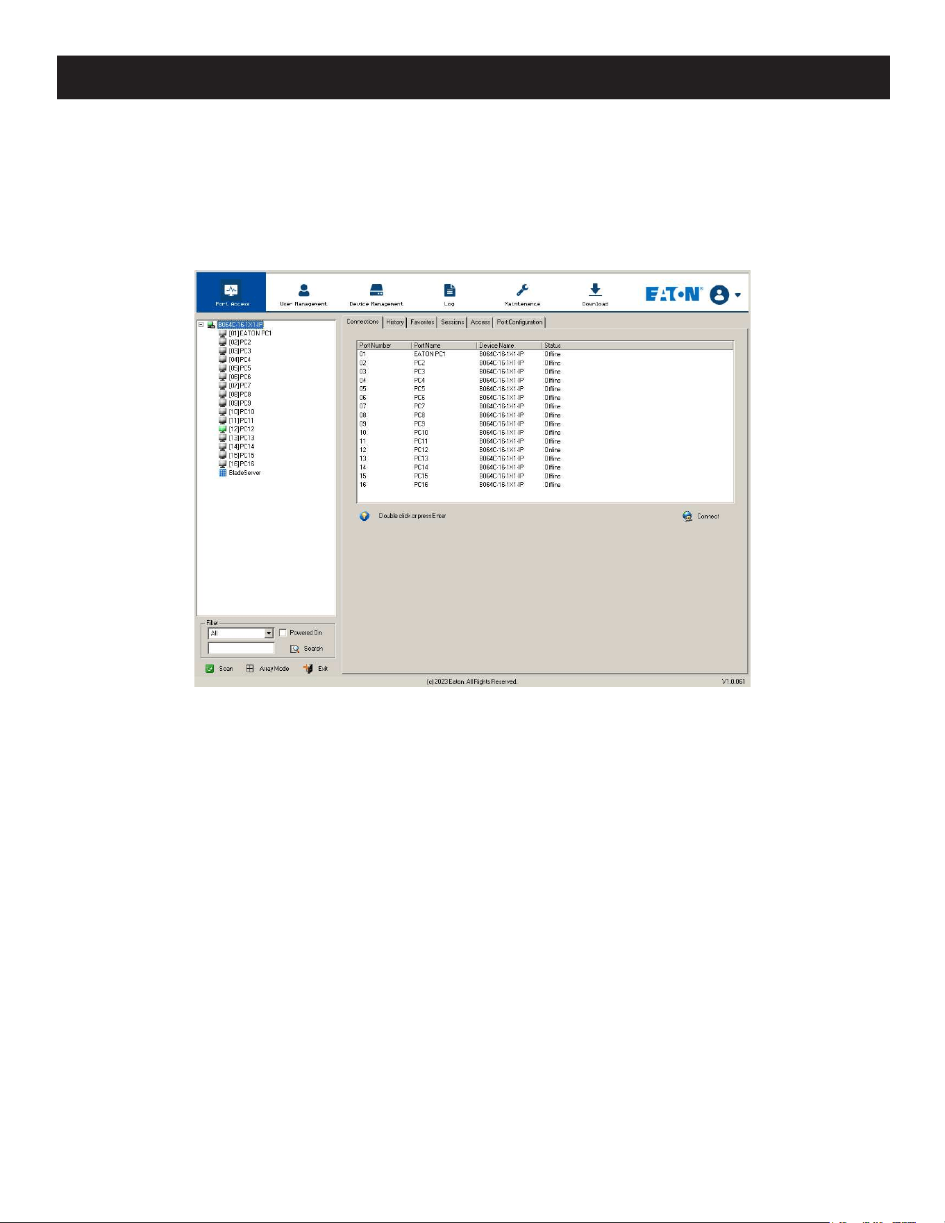
79
7. Administration
7.5.2 KVM Devices and Ports – Connections Page
The Connections page displays port status information at the device level, and port connection configuration options at
the port level.
Device Level
When a B064C-16-1X1-IP is selected in the Sidebar, the Connections page displays a list of ports for the device that the
user is authorized to access or view.
The following attributes are listed for each device:
• Port Number - the port’s number on the switch.
• Port Name - if a name has been assigned to a port, it displays here.
• Device Name - if a name has been assigned to the switch, it displays here.
• Status - the current status of the port - online or offline.
• Connect - You can access any port from the main panel by selecting it and clicking Connect.
Note: The sort order of the information displayed can be changed by clicking the column headings.
You can access a port from the main panel either by double-clicking anywhere on its line entry or selecting it anywhere
on its line entry and clicking Connect at the bottom right of the page.
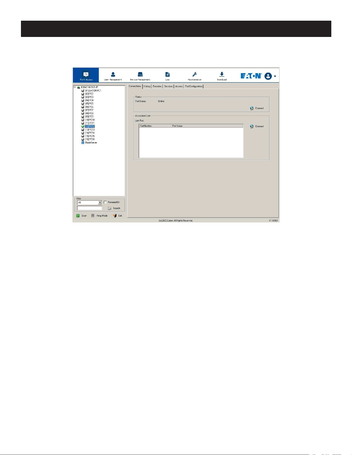
80
7. Administration
Port Level
When a port is selected in the Sidebar, the Connections page displays port connection configuration properties:
Status
The Status Panel displays the port’s current status information, including whether the port is online or offline and if the
port is mountable. See 7.5.8 Port Configuration for full details about the properties and how to configure them.
Click the Connect button to view the port display via the B064C-16-1X1-IP’s built-in Win Viewer (when using Windows
Internet Explorer) or Java Viewer (when using other web browsers).
Associated Link
The Associated Links panel displays ports that have been associated with the currently selected port. Associations are
configured on the Port Access Port Configuration Associated Links page.
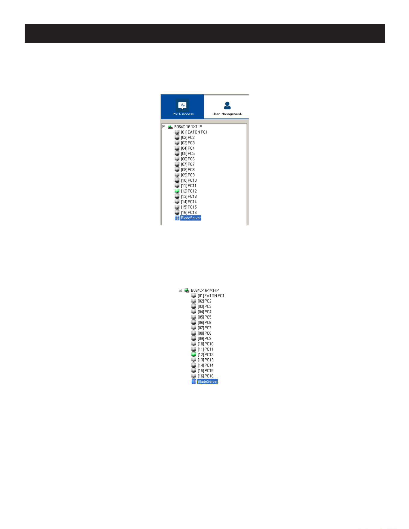
81
7. Administration
7.5.3 Blade Servers – Connections Page
Blade Servers connected to the switches display below the KVM switches in the Sidebar.
By associating a blade server or blade with a port, the servers and blades are integrated into the Sidebar tree view and
appear as devices connected to the port.
Blade Configuration Page
The Blade Configuration page is where the associations between the blade servers and the KVM switch ports get made.
To access this page, select the blade server or blade then click Blade Configuration (the menu item at the far right of the
menu bar).
For IBM and Dell blade servers, the entire chassis gets associated with a port and each blade in the chassis will appear
in the tree as a child port of the associated port – as in port 08 in the screenshot below.
For HP blade servers, associations are made on a blade-by-blade basis. Each blade is associated with a single port.
To access a blade, click on its port entry in the tree.
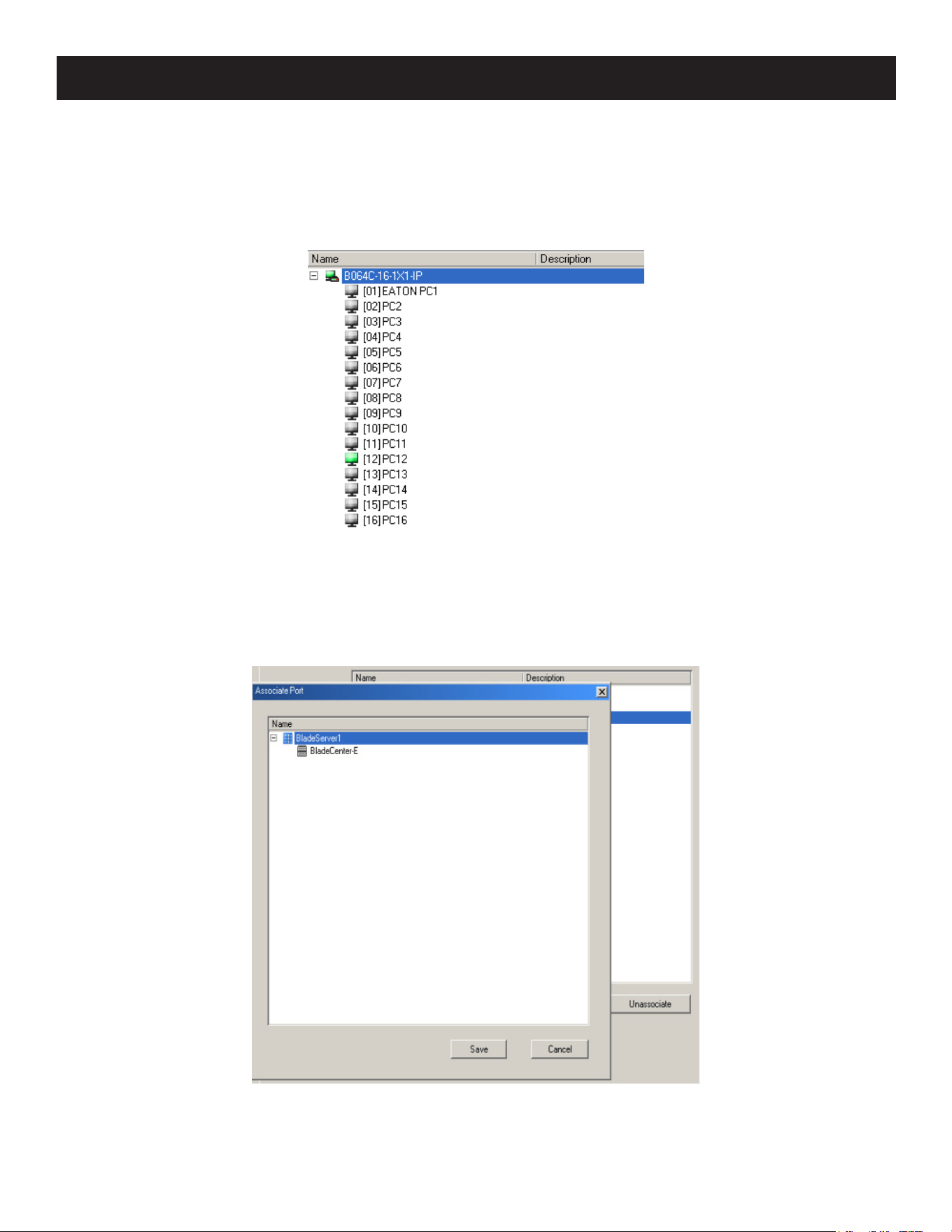
82
7. Administration
Associating Ports
Main Panel Device View
Port association begins by clicking the Blade Configuration menu item at the far right of the menu bar. The page
appears in Device View, listing all the KVM switch’s ports and blade servers (IBM and Dell servers) or individual blades
(HP servers) associated with them.
To make an association from the device view, first select a KVM port, then select a blade server or blade to associate it
with:
1. Select the port in the main panel.
2. Click Associate.
3. In the screen that appears, select the blade server or individual blade you want to associate with the selected port.
4. Click Save.
Once the association completes successfully, the blade icon will appear as the port indicator in the Sidebar tree. To
access the device running on the blade, click on its entry in the Sidebar.
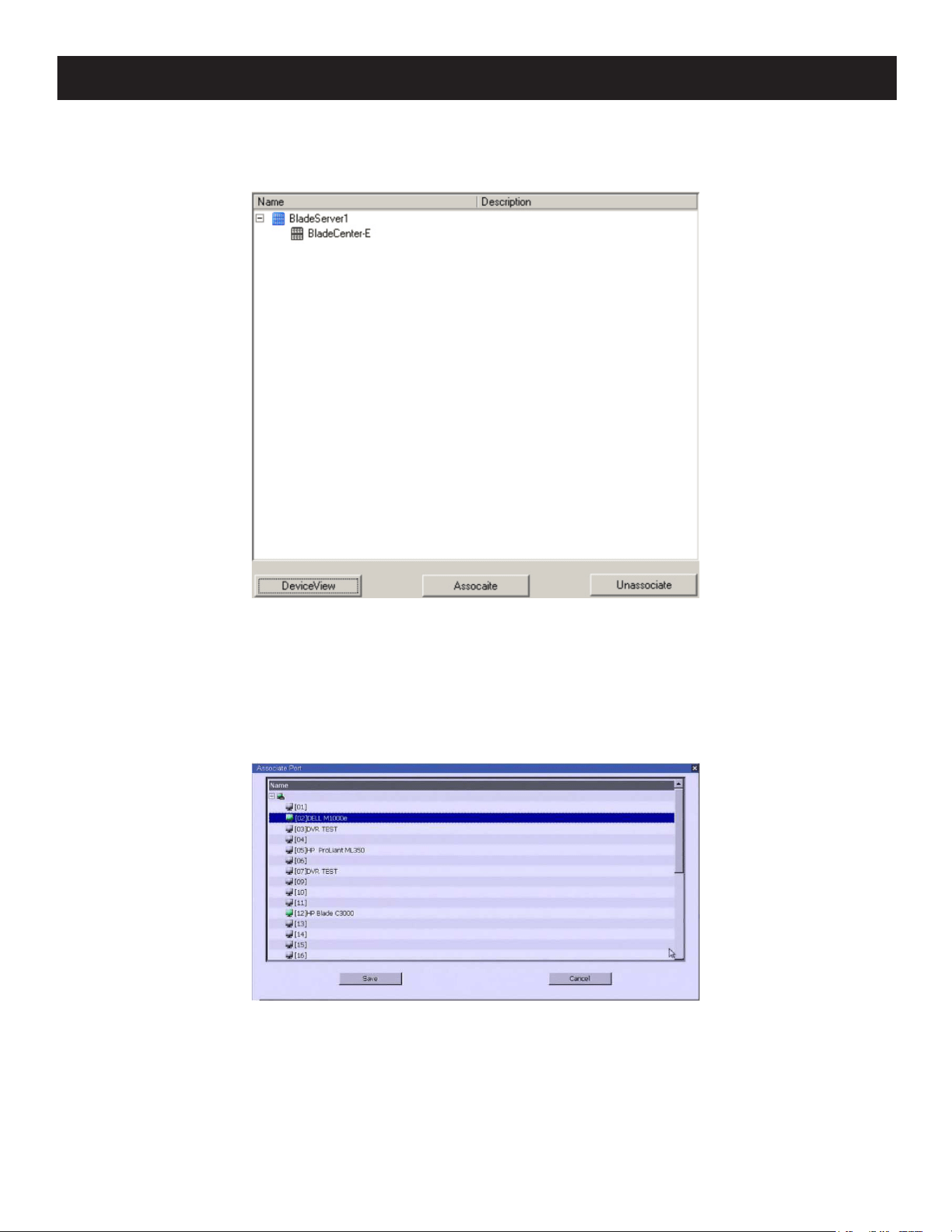
83
7. Administration
Main Panel Blade View
At the bottom of the Device View main panel is a button labeled Blade View. This is a button that toggles the main panel
between the two views. Click it to open the main panel in Blade View:
Blade View lists all the blade servers (IBM and Dell servers) and individual blades (HP servers) that are installed on the
system, as well as the ports (if any) they are associated with.
To make an association from the blade view, first select a blade server or blade, then select a KVM port to associate it
with:
1. Select the blade server or blade in the main panel.
2. Click Associate (at the bottom of the main panel).
3. In the screen that appears, select the port you want to associate it with.
4. Click Save.
After the association completes successfully, the blade icon will appear as the port indicator in the Sidebar tree. To
access the device running on the blade, click on its entry in the Sidebar.
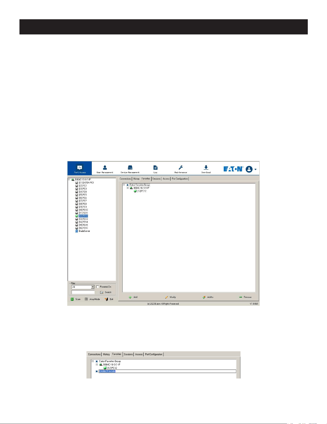
84
7. Administration
Unassociating Ports
To break the association between a port and a blade server or individual blade, select the association in the main panel,
then click Unassociate.
7.5.4 History
The History page provides a record of each time that a port was accessed and quick access to the most recently used
ports. You can access a port shown in the main panel by double-clicking it.
• If there are more entries than there is room on the screen, a scroll bar will appear to let you scroll up and down to
see the entire record.
• To clear the record and start over, click the Clear History button at the bottom right of the page.
Note: You can change the sort order of the information displayed by clicking the column headings.
7.5.5 Favorites
The Favorites page is similar to a bookmarks feature. Ports that you frequently access can be saved in a list here. Simply
open this page and select the port, rather than searching for it in the Sidebar. This feature is especially useful in large,
crowded installations.
Adding a Favorite
1. Right-click in the main panel, click Add Favorite.
– or –
Click Add at the bottom left of the main panel. An Untitled Favorite entry will appear:
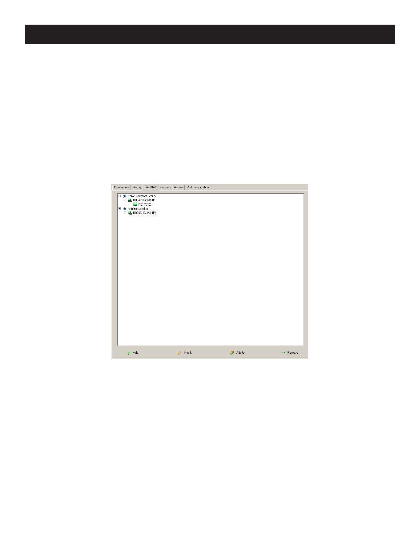
85
7. Administration
2. This will be a container to hold your port entries. Click inside the text entry box to erase Untitled Favorite and key in
an appropriate name, then click on any empty space in the main panel.
3. To add a port:
Drag it from the Sidebar and drop it onto the container.
– or –
Right-click on it in the Sidebar and select Copy. Right-click on the container, then select Paste.
– or –
Select the container in the main panel, select the port in the Sidebar, then click Add to at the bottom of the main
panel.
The switch that the port belongs to is added to the container and the selected port is appended under the switch.
Note: To add multiple ports at the same time, hold the Shift or Ctrl key down while you make your Sidebar selections then drag or
copy the entire group to the Favorites panel.
4. Repeat step 3 for any other Favorite categories you wish to create.
Note: Favorites can be selected for filtering in the Sidebar.
Modifying a Favorite
• To modify a Favorite or one of the items contained in it, right-click on it, then select a choice from the popup menu
that appears.
• To edit a Favorite’s name:
Click on it once, wait a moment, then click again. You can edit the name after the display changes to provide a text
input box. This is the same procedure as the one described for port naming.
– or –
Select the Favorite in the main panel, then click Modify at the bottom of the main panel.
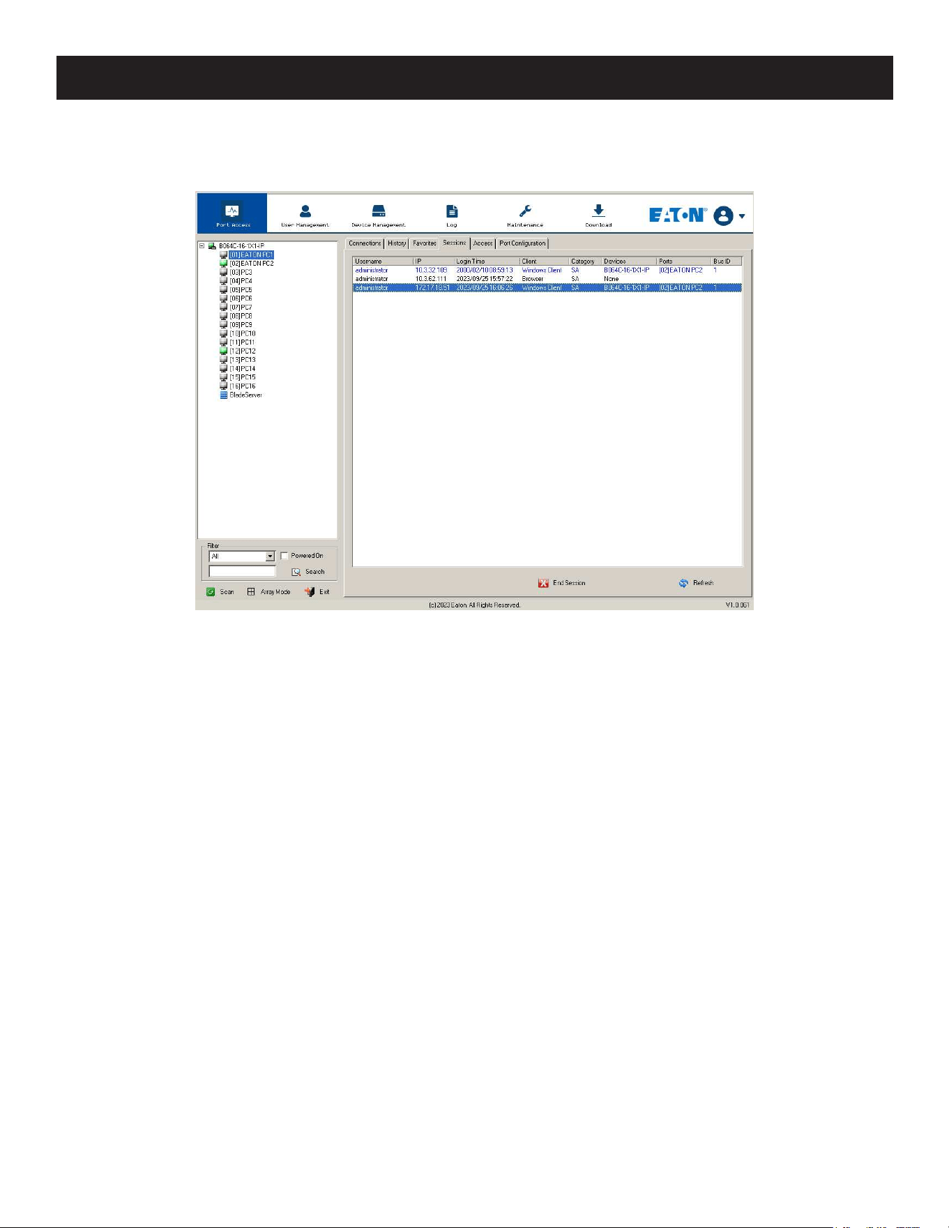
86
7. Administration
7.5.6 Sessions
The Session page lets the administrator and users with User Management permissions see at a glance which users are
currently logged into the KVM over IP switch and provides information about each of their sessions.
Notes:
• The Session page is not available for ordinary users.
• Users with User Management permissions can only see the sessions of ordinary users.
• The Category heading lists the type of user who has logged in: SA (Super Administrator), Admin (Administrator), Normal user (User).
The IP heading refers to the IP address that the user has logged in from and the Device and Port headings show which
device and port the user is currently accessing. The Bus ID refers to the bus that the user is currently on (Bus 0 refers
to the Local Console’s bus).
Notes:
• The sort order of the information displayed can be changed by clicking the column headings.
• The Bus ID also displays on the control panel.
This page also gives the administrator the option of forcing a user logout by selecting the user and clicking End Session
at the bottom of the main panel.
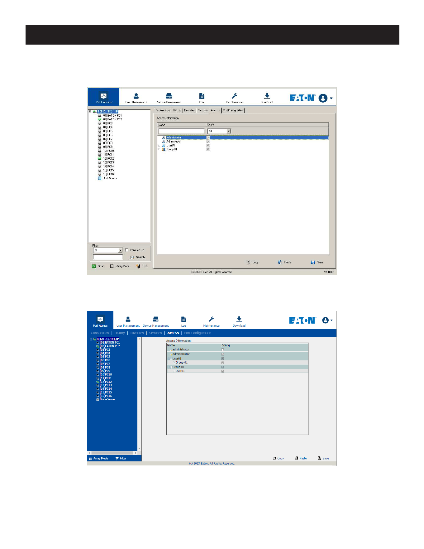
87
7. Administration
7.5.7 Access
Administrators use the Access page to set user and group access and configuration rights for switches and ports.
Note: The Access page only appears for those users with User Management permissions. It is not available for other users.
Device Level Browser GUI
If a switch is chosen in the Sidebar, the Main panel looks similar to the one shown below:
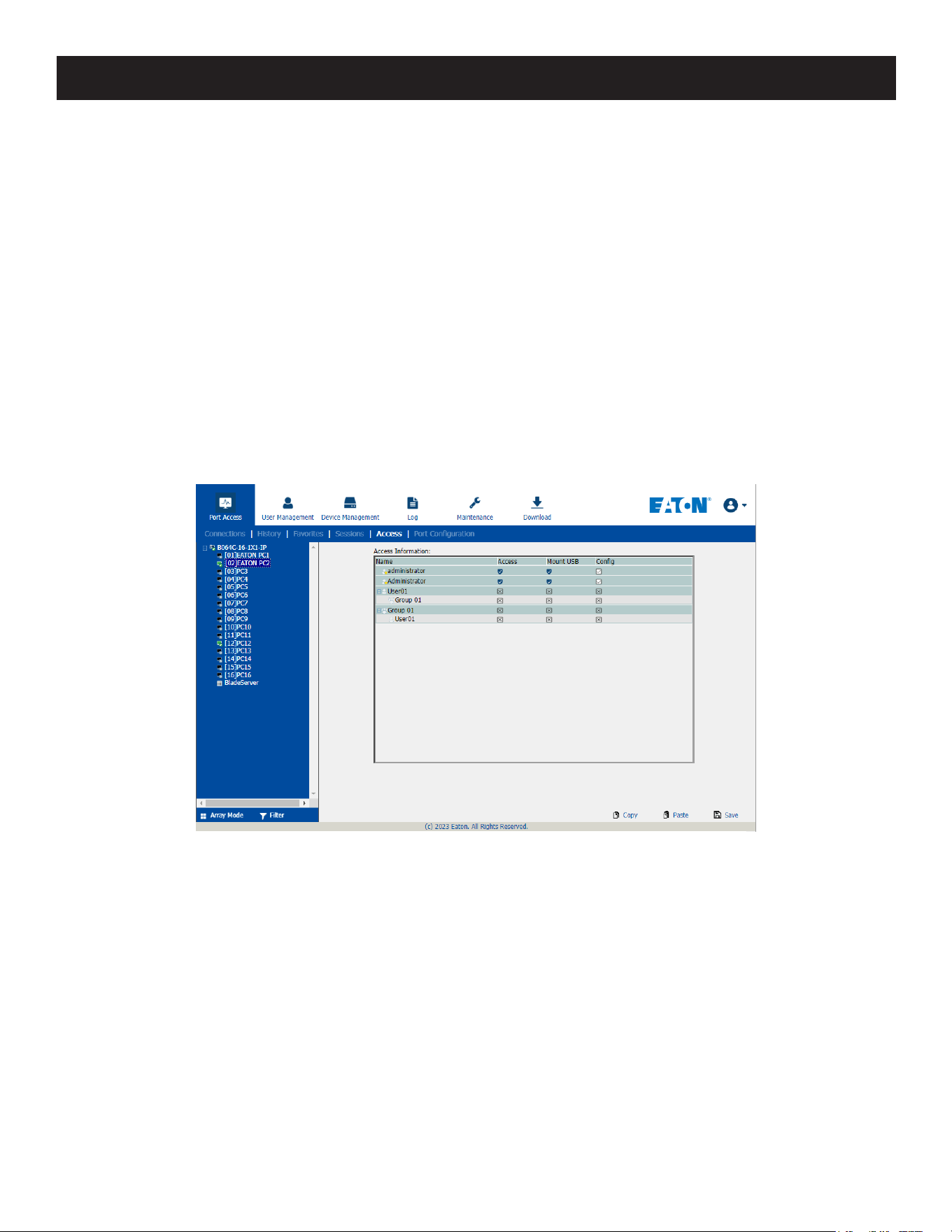
88
7. Administration
The main panel consists of two columns: Name, and Config:
• Name lists all the users and groups that have been created.
• Config indicates the users who have Configuration privileges. A check mark (√) indicates the user has permission to
make changes to the switch configuration settings (see 7.7 Device Management) and an X indicates the user is
denied permission to make configuration changes. Click the icon to toggle permission for Administrators and Users
(Super Administrators always have configuration privileges).
• The Copy and Paste buttons at the bottom of the main panel provide a shortcut method of assigning the permissions
settings of one port to any of the other ports. To do so:
1. Select the port whose permissions you want the other port(s) to follow.
2. Click Copy.
3. Select the port you want to receive the permissions.
4. Click Paste.
• When you have finished making your configuration changes, click Save.
Port Level Browser GUI Interface
If a port is chosen in the Sidebar, the Main panel looks similar to the one shown below:
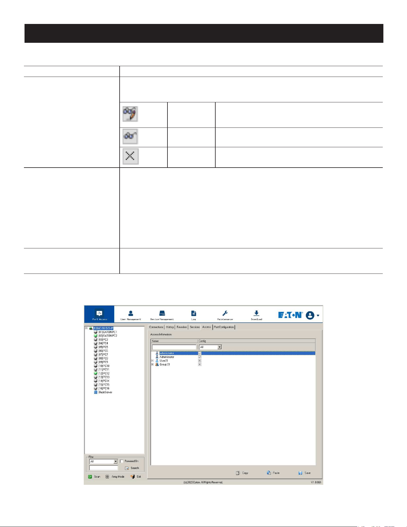
89
7. Administration
The port access settings are explained in the following table:
Name Each port accessible to the user is listed under the Names column.
Access
The Access column is where device access rights are set. To cycle through the choices,
click the icon in the row that corresponds to the user you want to congure. The
meanings of the icons are as follows:
Full Access
The user can view the remote screen and can perform
operations on the remote server from his keyboard
and monitor.
View Only
The user can only view the remote screen and cannot
perform any operations on it.
No Access
No access rights - the Port will not appear on the
User's list on the Main Screen.
Mount USB
The Mount USB column is where permission to mount Virtual Media devices on
remote servers is congured. To cycle through the choices, click the icon in the row
that corresponds to the user you want to congure. The icons are the same as the
ones in the Access column.
• With a Full Access setting, the user can mount, read and write to the virtual media.
• With a View Only setting, the user can only view the contents of the virtual media
(read only) and cannot perform any operations on it.
• With a No Access setting, the user will not see the virtual media, even if it has been
congured on the remote system.
Note: This entry does not appear for switches that do not support the USB Virtual Media function.
Cong
Sets or denies permission for the user to make changes to a port’s conguration
settings. A check mark (√) indicates that the user has permission and an X means that
the user does not have permission.
Device Level AP GUI Interface
If a switch is chosen in the Sidebar, the Main panel looks similar to the one below:
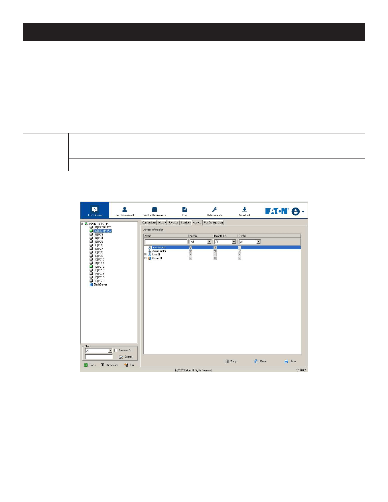
90
7. Administration
The page is essentially the same as the one for the Browser GUI, with the exception that there are filters at the top of
the columns. The filters allow you to expand or limit the scope of the users and groups that are displayed, as described
in the following table:
Filter Description
Name
To lter on the User or Group name, key in the name or partial name and press Enter.
Only Users and Groups whose names correspond to what you have keyed in will
appear in the list.
Wildcards (? for single characters; * for multiple characters) and the keyword “or” are
supported. For example, h*ds would return hands and hoods; h?nd would return hand
and hind, but not hard; h*ds or h*ks would return hands and hooks.
Cong
All All Users and Groups appear in the list.
Permitted Only Users and Groups with conguration permissions appear in the list.
Restricted Only Users and Groups that do not have conguration permissions appear in the list.
Port Level AP GUI Interface
If a port is chosen in the Sidebar, the Main panel will appear similar to the one below:
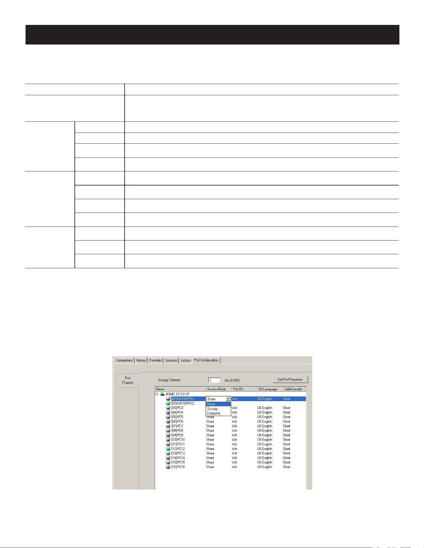
91
7. Administration
The page is essentially the same as the one for the Browser GUI, with the exception that there are filters at the top of
the columns. The filters allow you to expand or limit the scope of the users and groups that are displayed, as described
in the following table:
Filter Description
Name
To lter on the User or Group name, key in the name, partial name, or partial name
and wild card ( * ) then press Enter. Only the Users and Groups whose names
correspond to what you have keyed in appear in the list.
Access
All All Users and Groups appear in the list.
Full Access Only Users and Groups with Full Access permissions appear in the list.
View Only Only Users and Groups with View Only permissions appear in the list.
No Access Only Users and Groups with No Access permissions appear in the list.
Mount USB
All All Users and Groups appear in the list.
Full Access Only Users and Groups with Full Access Mount USB permissions appear in the list.
Read Only Only Users and Groups with Read Only Mount USB permissions appear in the list.
No Access Only Users and Groups with No Access Mount USB permissions appear in the list.
Cong
All All Users and Groups appear in the list.
Permitted Only Users and Groups with Permitted Cong permissions appear in the list.
Restricted Only Users and Groups with Restricted Cong permissions appear in the list.
Saving Changes
Click the Save button at the lower right corner of the page to save any changes made on the Access page.
7.5.8 Port Configuration
Device Level
When a device is selected in the Sidebar, the only item available under Port Configuration is the Port Properties page
with one field to configure: the Occupy Timeout setting.
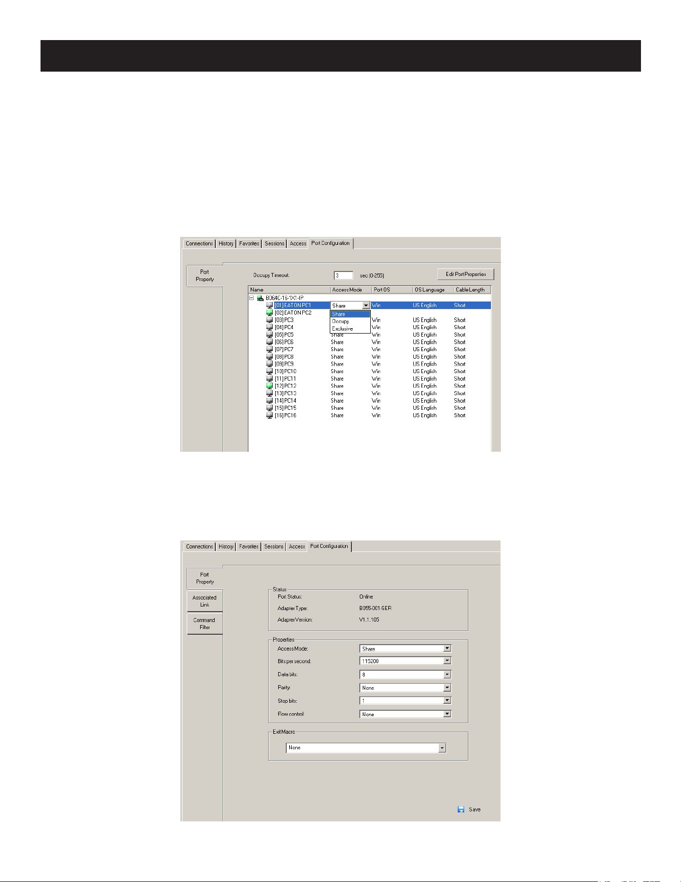
92
7. Administration
The Occupy Timeout field sets a time threshold for users on ports whose Access Mode has been set to Occupy. If there
is no activity from the user occupying the port for the time duration set here, the user is timed out and the port is
released. The first user to send keyboard or mouse input after the port has been released gets to occupy the port.
Input a value from 0 to 255 seconds. The default is 3 seconds. A setting of 0 causes the port to be released the instant
there is no input.
Edit Port Properties
Click Edit Port Properties to list ports and use the drop-down menus to configure Access Mode, Port OS, OS Language
and Cable length settings.
You can also use the [Shift] and/or [ctrl] keys to select and configure multiple ports.
Port Level
Port Properties
When a port is selected in the Sidebar, the Port Properties page looks similar to the one shown below:

93
7. Administration
• The Status panel provides information as to whether the port is online or offline, the adapter cable used to connect
the server (or other device) to the port and the adapter’s firmware level.
• The Properties panel allows you to make configuration settings for the selected port.
• The Macro panel contains a dropdown listbox of user created System macros. You can select a macro from the list
that will execute when exiting the remote server.
An explanation of the configuration fields is given in the table below:
Field Explanation
Access Mode
Denes how the port is to be accessed when multiple users have logged on.
Exclusive: The rst user to switch to the port has exclusive control over the port. No
other users can view the port. The Timeout function does not apply to ports which
have this setting.
Occupy: The rst user to switch to the port has control over the port. However,
additional users may view the port’s video display. If the user who controls the port is
inactive for longer than the time set in the Timeout box, port control is transferred to
the rst user to move the mouse or strike the keyboard.
Share: Users simultaneously share control over the port. Input from the users is
placed in a queue and executed chronologically. Under these circumstances, users
can take advantage of the Message Board, which allows users to communicate with
each other regarding control of the keyboard and mouse or keyboard, mouse, and
video of a Share port.
Port OS
Species the operating system that the server on the connected port is using. Choices
are Win, Mac, Sun and Other. The default is Win.
OS Language
Species the OS language being used by the server on the connected port. Use the
drop-down list to see the available choices. The default is English US.
Cable Length
Lets you specify how long the Cat 5e/6 cable between the port and the KVM adapter
cable is. Use the drop-down menu to select the cable length settings:
Short: up to 82 ft. (25 m)
Medium: between 65 and 115 ft. (20 and 35 m)
Long: above 115 ft. (35 m)
Once you have finished making your configuration changes, click Save.
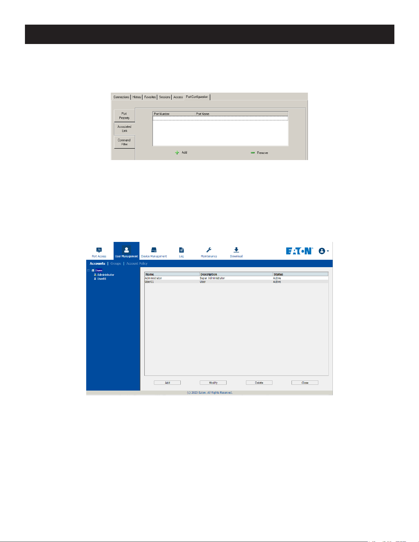
94
7. Administration
Associated Links
The Associated Links page provides a method of associating other ports on the same switch to the selected port. This
function is primarily intended to be used when connecting both KVM and serial ports (KA7140) from a single server to
the switch.
• To associate a port with the currently selected one, click Add. In the dialog box that appears, key in the port’s
number, then click OK. The port’s number and name appear in the main panel.
• To remove an unwanted associated port, select it in the main panel, then click Remove.
7.6 User Management
When you select the User Management tab the screen opens with the Users page displayed:
Browser GUI
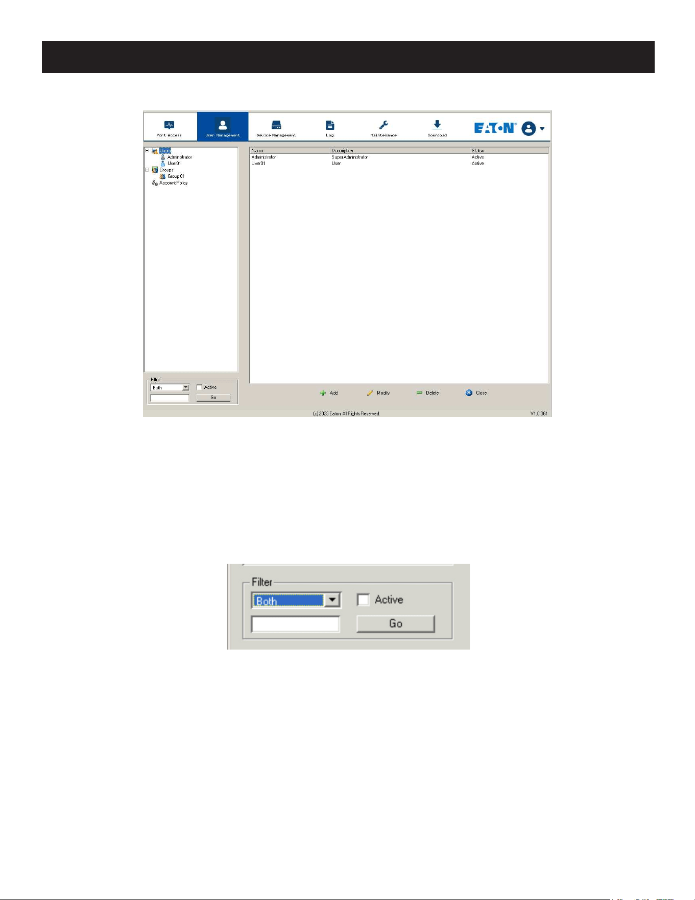
95
7. Administration
AP GUI
The page is organized into two main areas: the Sidebar at the left, and the large main panel at the right.
• Users and groups appear in the panel at the left of the page. The large panel at the right provides more detailed
information for each.
o The Browser GUI has separate menu bar entries for Accounts (Users) and Groups. Depending on the menu item
selected, either Users or Groups are listed in the Sidebar.
o The AP GUI does not have menu entries. Instead, Users and Groups are listed separately in the Sidebar.
• In the Browser GUI, the sort order of the information displayed can be changed by clicking the main panel column
headings.
• In the AP GUI, the section below the Sidebar list provides a filter that allows you to manage the list:
• Click the arrow at the right of the list box to select whether you want to view only Users, only Groups, or both Users
and Groups.
• Click to put a check in the Active checkbox to filter out any users whose accounts are not active.
• To only select Users or Groups that match a particular string, key it into the text box in front of the Go button, then
click Go. Only Users or Groups that match the string will appear in the list.
• Wildcards (? for single characters; * for multiple characters) and the keyword “or” are supported. For example, h*ds
would return “hands” and “hoods”, h?nd would return “hand” and “hind”, but not “hard”, and h*ds or h*ks would
return “hands” and “hooks”.
• The buttons below the main panel are used to manage users and groups.
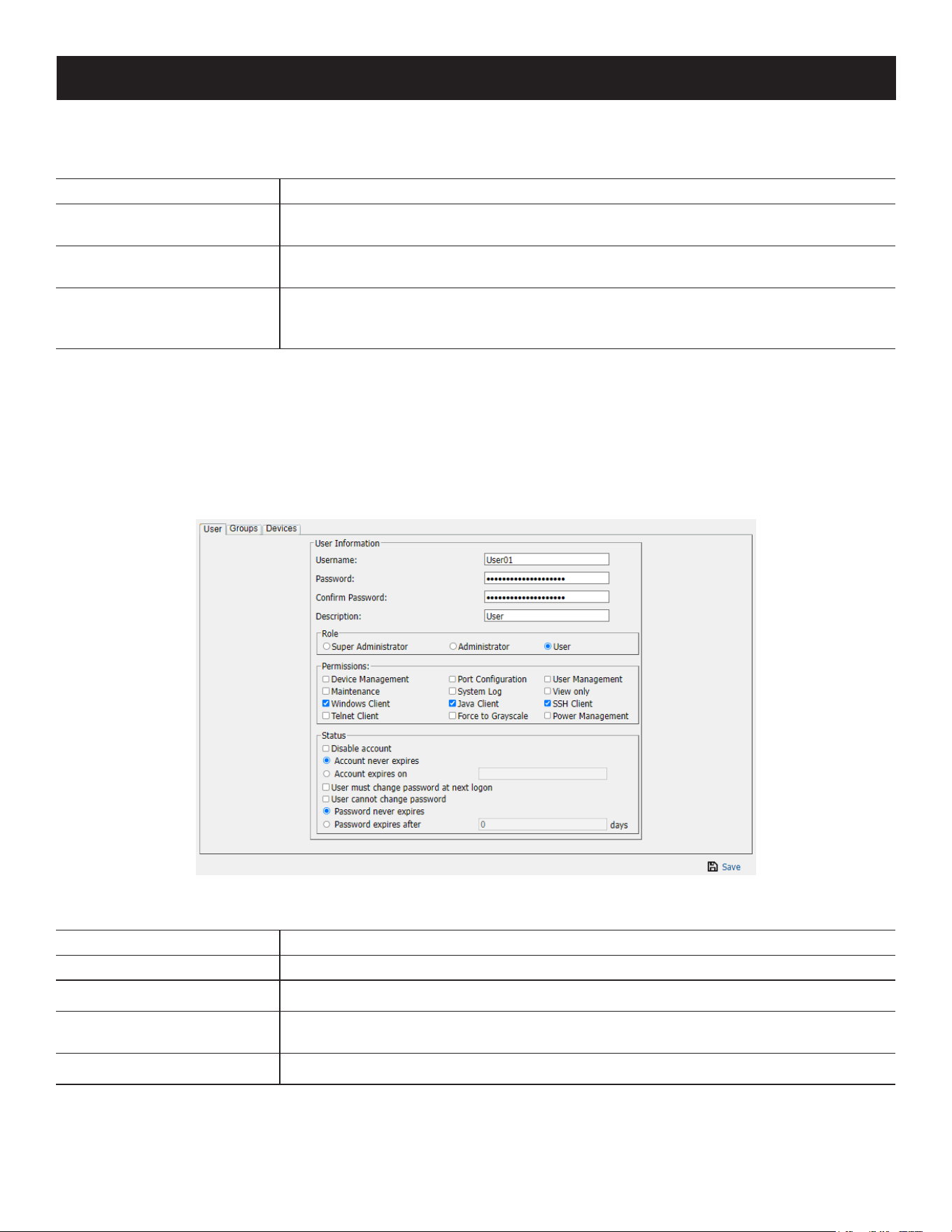
96
7. Administration
7.6.1 Users
The B064C-16-1X1-IP supports three types of user accounts:
User Type Role
Super Administrator
Access and manage ports and devices. Manage Users. Congure the overall
installation. Congure personal working environment.
Administrator
Access and manage authorized ports and devices. Manage Users. Congure personal
working environment.
User
Access authorized ports and devices. Manage authorized ports and devices. Congure
personal working environment.
Note: Users who have been given permission to do so may also manage other users.
Adding Users
To add a user and assign user permissions:
1. Select Users in the Sidebar (Browser GUI)
- or -
Select Users in the Sidebar (AP GUI).
2. To add a user, click Add at the bottom of the main panel. The User notebook opens, with the User tab selected:
3. Enter the required information in the appropriate fields. A description of each of the fields is given in the table
below:
Field Description
Username Enter a username from 1 to 16 characters, depending on the Account Policy settings.
Password Enter a password from 0 to 32 characters, depending on the Account Policy settings.
Conrm Password
To ensure there is no mistake in the password, you will be asked to enter it again. The
two entries must match.
Description Additional information about the user that you may wish to include.

97
7. Administration
Field Description
Role
There are three categories: Super Administrator, Administrator and User. There is no
limitation on the number of accounts that can be created in each category.
• The Super Administrator is responsible for the overall installation conguration
and maintenance, user management and device and port assignments. The Super
Administrator’s permissions are automatically assigned by the system and cannot be
altered.
• The default permissions for Administrators include everything except Force to
Grayscale, but the permissions can be altered for each Administrator by checking or
unchecking any of the permissions checkboxes.
• The default permissions for Users include the Win, Java, and SSH clients, but the
permissions can be altered for each User by checking or unchecking any of the
permissions checkboxes.
Note: Users who have been given User Management privileges cannot access or congure Groups.
Permissions
Note: For ordinary users, in
addition to enabling Device
Management, Port Conguration,
and Maintenance permissions,
the user must also be given those
rights for each device and port
that he will be allowed to manage.
See 7.6.4 Device Assignment for
details.
• Enabling Device Management allows a user to congure and control the settings for
overall operations (see 7.7 Device Management).
• Enabling Maintenance allows a user to perform all the Maintenance operations
available under the Maintenance tab (see 7.9 Maintenance).
• Enabling Windows Client allows a user to download the Windows Client AP software
and access the B064C-16-1X1-IP with it, in addition to (or instead of) the browser
access method.
• Enabling Port Conguration allows a user to congure and control the settings for
individual ports (see 7.5.8 Port Conguration).
• Enabling System Log allows a user to access the system log (see 7.8 Log).
• Enabling Java Client allows a user to download the Java Client AP software and
access the B064C-16-1X1-IP with it, in addition to (or instead of) the browser access
method.
• Enabling SSH Client allows a user to log in and access the KVM over IP switch via an
SSH session.
• Enabling Telnet Client allows a user to log in and access the KVM over IP switch via a
Telnet session.
• Enabling User Management allows a user to create, modify and delete user and
group accounts.
• Enabling View Only limits users to only being able to view the display of connected
devices. They cannot control port access, nor can they input any keyboard or mouse
signals to the devices they view.
• Force to Grayscale forces the user’s view of the remote display to be in grayscale.
This can speed up I/O transfer in low bandwidth situations.
Status
Status allows you to control the user’s account and access the installation.
• Disable Account lets you suspend a user’s account without actually deleting it, so that
it can be easily reinstated in the future.
• If you do not want to limit the time scope of the account, select Account never
expires; if you do want to limit the amount of time that the account remains in eect,
select Account expires on and key in the expiration date.
• To require a user to change their password at the next log on, select User must
change password at next logon. This can be used by the administrator to give the
user a temporary password to log in for the rst time, then let the user set the
password of their choice for future logins.
• To make a password permanent so the user cannot change it to something else,
select User cannot change password.
• For security purposes, administrators may want users to change their passwords
periodically.
o If not, select Password never expires. This allows users to keep their current
passwords for as long as they like.
o If so, select Password expires after, and key in the number of days allowed before
the password expires. Once the time is up, a new password must be set.

98
7. Administration
4. At this point you can assign the new user to a group by selecting the Groups tab. You can also assign the user’s port
access rights by selecting the Devices tab.
Note: Optionally, you can skip this step now and return to it later.
5. When your selections have been made, click Save.
6. When the Operation Succeeded message appears, click OK.
7. Click Users in the Sidebar to return to the main screen. The new user will in the Sidebar list and in the main panel.
o The Sidebar Users list can expand and collapse. If the list is expanded, click the minus symbol ( - ) next to the
Users icon to collapse it; if it is collapsed there is a plus symbol ( + ) next to the icon. Click the plus symbol to
expand it.
o The icon for administrators has one red band.
o The large main panel shows the user’s name; the description that was given when the account was created; and
whether the account is currently active or has been disabled.
Modifying User Accounts
To modify a user account:
1. In the Sidebar User list, click the user’s name
- or -
In the main panel, select the user’s name.
2. Click Modify.
3. In the User page that opens, make your changes, then click Save.
Deleting User Accounts
To delete a user account:
1. In the main panel, select the user’s name.
2. Click Delete.
3. Click OK.
7.6.2 Groups
Groups allow administrators to manage users and devices with ease and efficiency. Since device access rights apply to
anyone who is a member of the group, administrators only need to set them once for the group, rather than setting
them for each user individually. Multiple groups can be defined to allow some users access to specific devices, while
restricting other users from accessing them.
Creating Groups
To create a group:
1. Select Groups on the menu bar (Browser GUI)
– or –
Select Groups in the Sidebar (AP GUI).
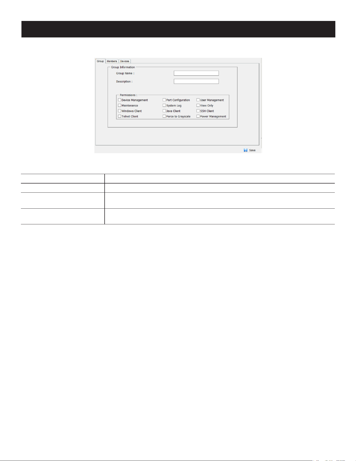
99
7. Administration
2. Click Add at the bottom of the main panel. The Group notebook opens, with the Group tab selected:
3. Enter the required information in the appropriate fields. A description of each of the fields is provided in the table
below:
Field Description
Group Name A maximum of 16 characters is allowed.
Description
Additional information about the user that you may wish to include. A maximum of 63
characters is allowed.
Permissions
Permissions and restrictions for groups are set by checking the appropriate boxes.
These are the same permissions as the ones specied for Users.
4. You can now assign users to the group by selecting the Members tab. You can also assign the group’s port access
rights by selecting the Devices tab.
Note: Optionally, you can skip this step and return to it later.
5. Once your selections have been made, click Save.
6. When the Operation Succeeded message appears, click OK.
7. Click Group in the Sidebar to return to the main screen. The new group will in the Sidebar Group list and in the main
panel.
• The Sidebar Group list can expand and collapse. If the list is expanded, click the minus symbol ( – ) next to the
Users icon to collapse it. If it is collapsed, there is a plus symbol ( + ) next to the icon. Click the plus symbol to
expand it.
• The large main panel shows the group’s name and the description that was given when the group was created (the
Status column is inactive).
Repeat the procedure to add additional groups.
Note: You must perform Step 7 before attempting to add a new group. Otherwise, the new group you are creating will replace the group
you just finished creating.
Modifying Groups
To modify a group:
1. In the Sidebar Group list, click the group’s name.
– or –
In the main panel, select the group’s name.
2. Click Modify.
3. In the Group notebook that comes up, make your changes, then click Save.
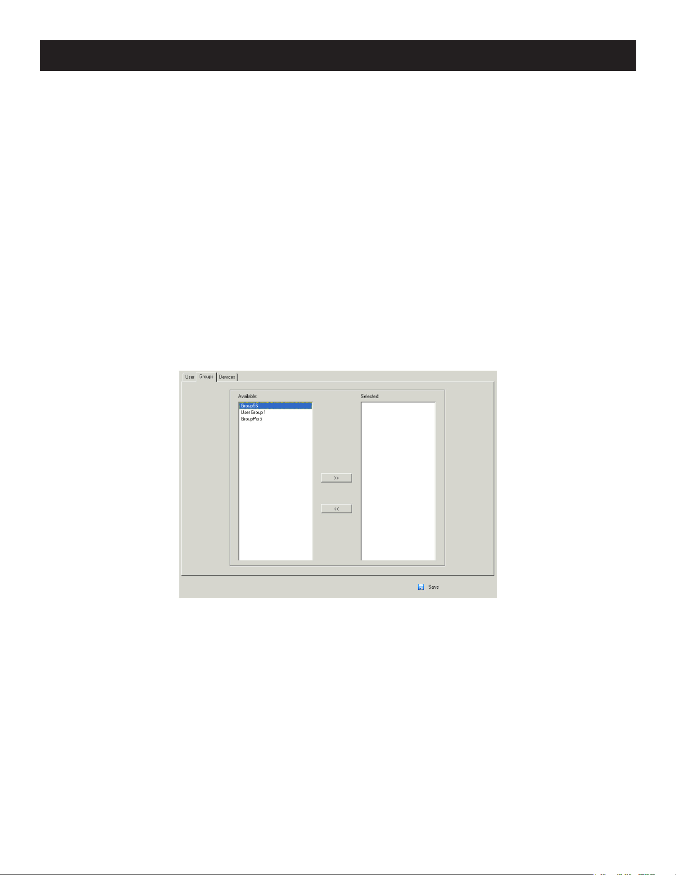
100
Deleting Groups
To delete a group:
1. In the Sidebar, click the Groups icon.
2. In the main panel, select the group’s name.
3. Click Delete.
4. Click OK.
7.6.3 Users and Groups
There are two ways to manage users and groups: from the Users notebook and from the Group notebook.
Note: Before you can assign users to groups, you must first create them.
Assigning Users to a Group from the User’s Notebook
1. In the Sidebar User list, click the user’s name.
– or –
In the main panel, select the user’s name.
2. Click Modify.
3. In the User notebook that appears, select the Groups tab.
4. In the Available column, select the group that you want the user to be in.
5. Click the Right Arrow to put the group’s name into the Selected column.
6. Repeat the above for any other groups that you want the user to be in.
7. Click Save when you are done.
Note: If a user has permissions in addition to those assigned to the group, the user keeps those permissions in addition to the group
ones.
7. Administration
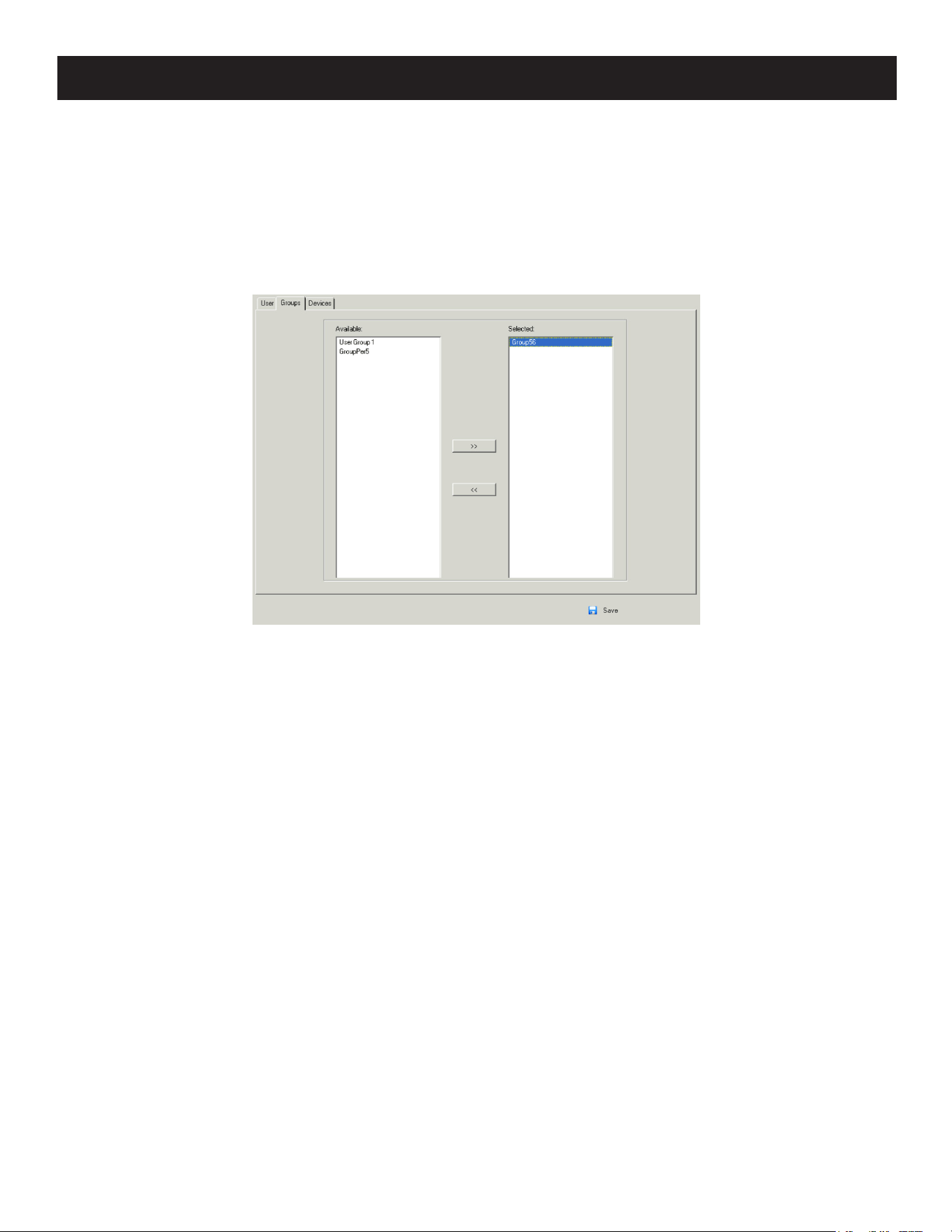
101
7. Administration
Removing Users from a Group from the User’s Notebook
To remove a user from a group from the User’s notebook:
1. In the Sidebar User list, click the user’s name
– or –
In the main panel, select the user’s name.
2. Click Modify.
3. In the User notebook that comes up, select the Groups tab.
4. In the Selected column, select the group that you want to remove the user from.
5. Click the Left Arrow to remove the group’s name from the Selected column (it goes back into the Available column).
6. Repeat the above for any other groups that you want to remove the user from.
7. Click Save when you are done.
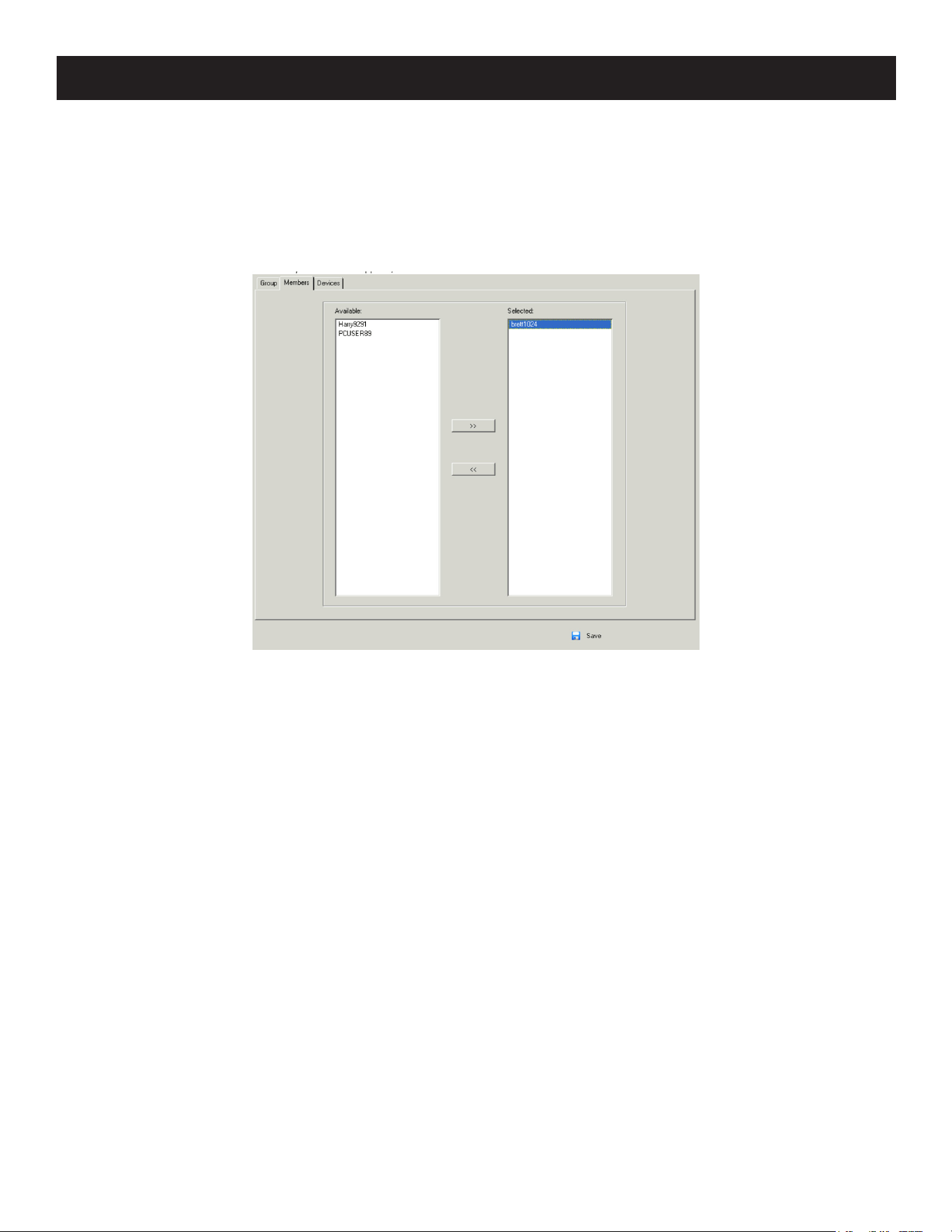
102
7. Administration
Assigning Users to a Group from the Group’s Notebook
1. In the Sidebar Group list, click the group’s name
– or –
In the main panel, select the group’s name.
2. Click Modify.
3. In the Group notebook that appears, select the Members tab.
4. In the Available column, select the user that you want to be a member of the group.
5. Click the Right Arrow to put the user’s name into the Selected column.
6. Repeat the above for any other users that you want to be members of the group.
7. Click Save when you are done.
Note: If a user has permissions in addition to the ones assigned to the group, the user keeps those permissions in addition to the
group ones.
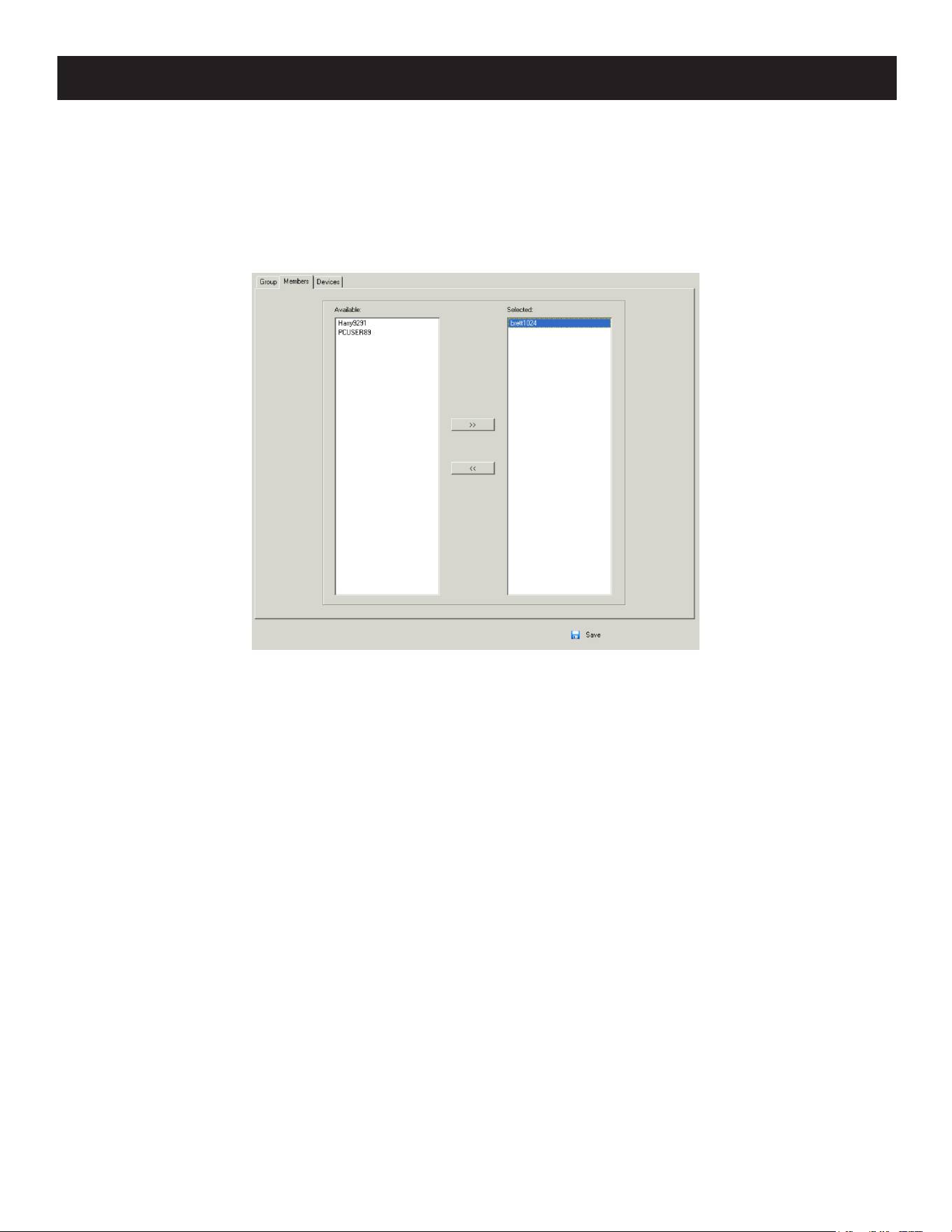
103
7. Administration
Removing Users from a Group from the Group’s Notebook
1. In the Sidebar Group list, click the group’s name
– or –
In the main panel, select the group’s name.
2. Click Modify.
3. In the Group notebook that comes up, select the Members tab.
4. In the Selected column, select the user that you want to remove from the group.
5. Click the Left Arrow to remove the user’s name from the Selected column (it goes back into the Available column).
6. Repeat the above for any other users that you want to remove from the group.
7. Click Save when you are done.
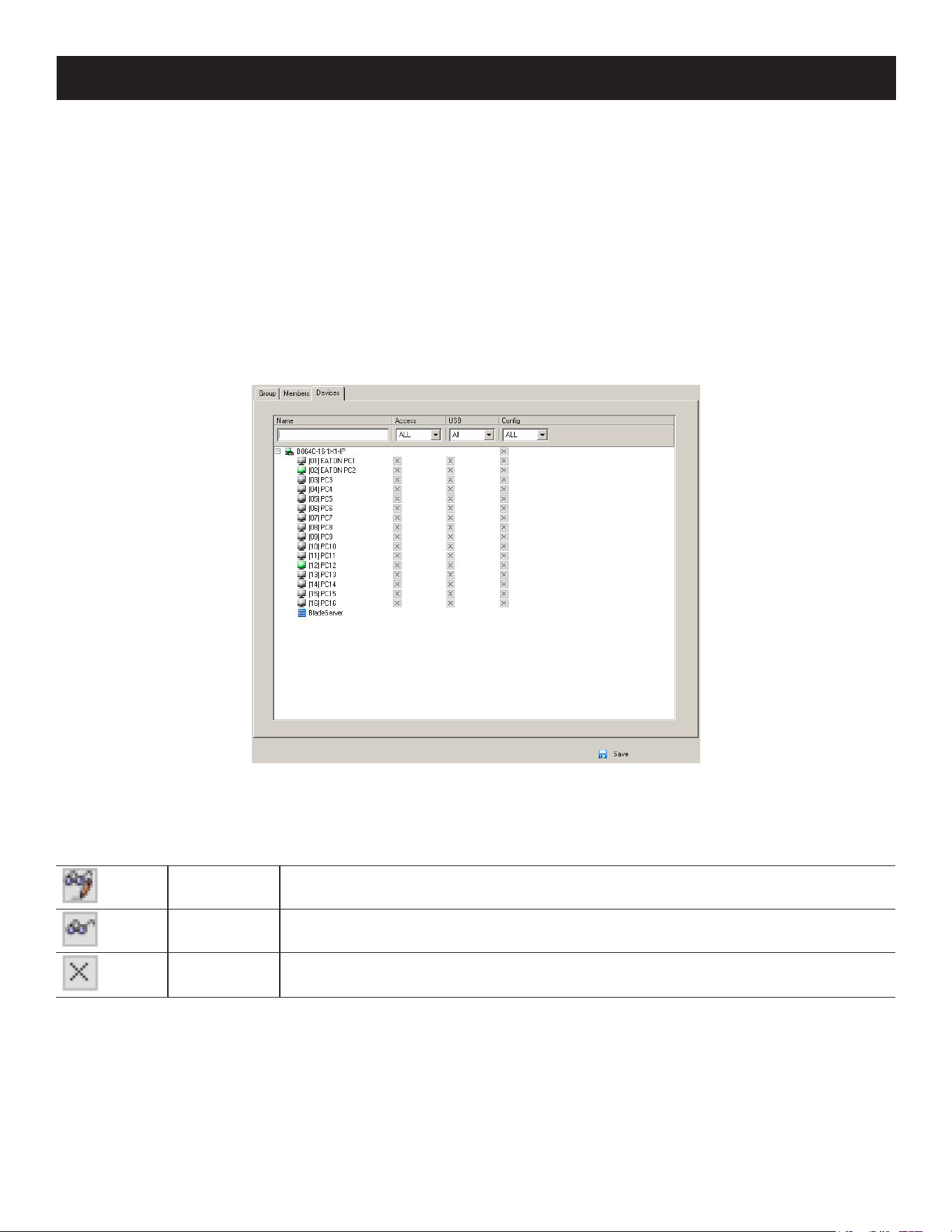
104
7. Administration
7.6.4 Device Assignment
When a user logs in to the KVM over IP switch, the interface will appear with the Port Access page displayed. All ports
that the user are permitted to access are listed in the Sidebar at the left of the page. Access permissions for those
ports and the devices connected to them are assigned on a port-by-port basis from the User or Group list on the
Sidebar of the User Management page.
Assigning Device Permissions from the User’s Notebook
1. In the Sidebar User list, click the user’s name
– or –
In the main panel, select the user’s name.
2. Click Modify.
3. In the User notebook that appears, select the Devices tab.
4. Make your permission settings for each port according to the information provided below:
Name: Each port accessible to the user is listed under the Names column.
Access: The Access column is where device access rights are set. Click the icon in the row that corresponds to the
port you want to configure to cycle through the choices. The meanings of the icons are described in the table below:
Full Access
The user can view the remote screen and can perform operations on the remote
server from his keyboard and monitor.
View Only The user can only view the remote screen; he cannot perform any operations on it.
No Access No access rights - the Port will not show up on the User’s list on the Main Screen.

105
7. Administration
USB: The USB column is where USB Virtual Media device access rights are listed. This entry does not appear for
switches that do not support the USB Virtual Media function. Click the icon in the row that corresponds to the port
you want to configure to cycle through the choices.
• With Full Access, the User can mount, read and write the virtual media.
• With View Only, the user can only read already mounted virtual media data.
Config: The Config column is where a user’s permission to make changes to a port’s configuration settings are
permitted/restricted. Click the icon in the row that corresponds to the port you want to configure to cycle through
the choices.
A check mark (√) indicates the user has permission to make changes to the port’s configuration settings and an X
indicates the user is denied permission to make configuration changes.
5. Once you have finished making your choices, click Save.
6. In the confirmation popup that appears, click OK.
Note: In any of the columns, you can use Shift-Click or Ctrl-Click to select a group of ports to configure. Clicking to cycle through the
choices on any one of the selected ports causes all of them to cycle in unison.
Filters
There are four filters at the top of the columns that allow you to expand or limit the scope of the ports displayed in the
Name column.
Filter Description
Name
To lter on the port name, key in the name then press Enter. Only the ports whose
names correspond to what you have keyed in appear in the list.
Wildcards (? for single characters; * for multiple characters) and the keyword or are
supported. For example, h*ds would return “hands” and “hoods”, h?nd would return
“hand” and “hind”, but not “hard”, h*ds or h*ks would return “hands” and “hooks”.
Access
All All ports appear in the list.
Full Access Only ports congured as Full Access ports appear in the list.
View Only Only ports congured as View Only ports appear in the list.
No Access Only ports congured as No Access ports appear in the list.
USB
All All ports appear in the list.
Full Access Only ports congured as Full Access USB ports appear in the list.
Read Only Only ports congured as Read Only USB ports appear in the list.
No Access Only ports congured as No Access USB ports appear in the list.
Cong
All All ports appear in the list.
Permitted Only ports congured as Permitted appear in the list.
Restricted Only ports congured as Restricted appear in the list.
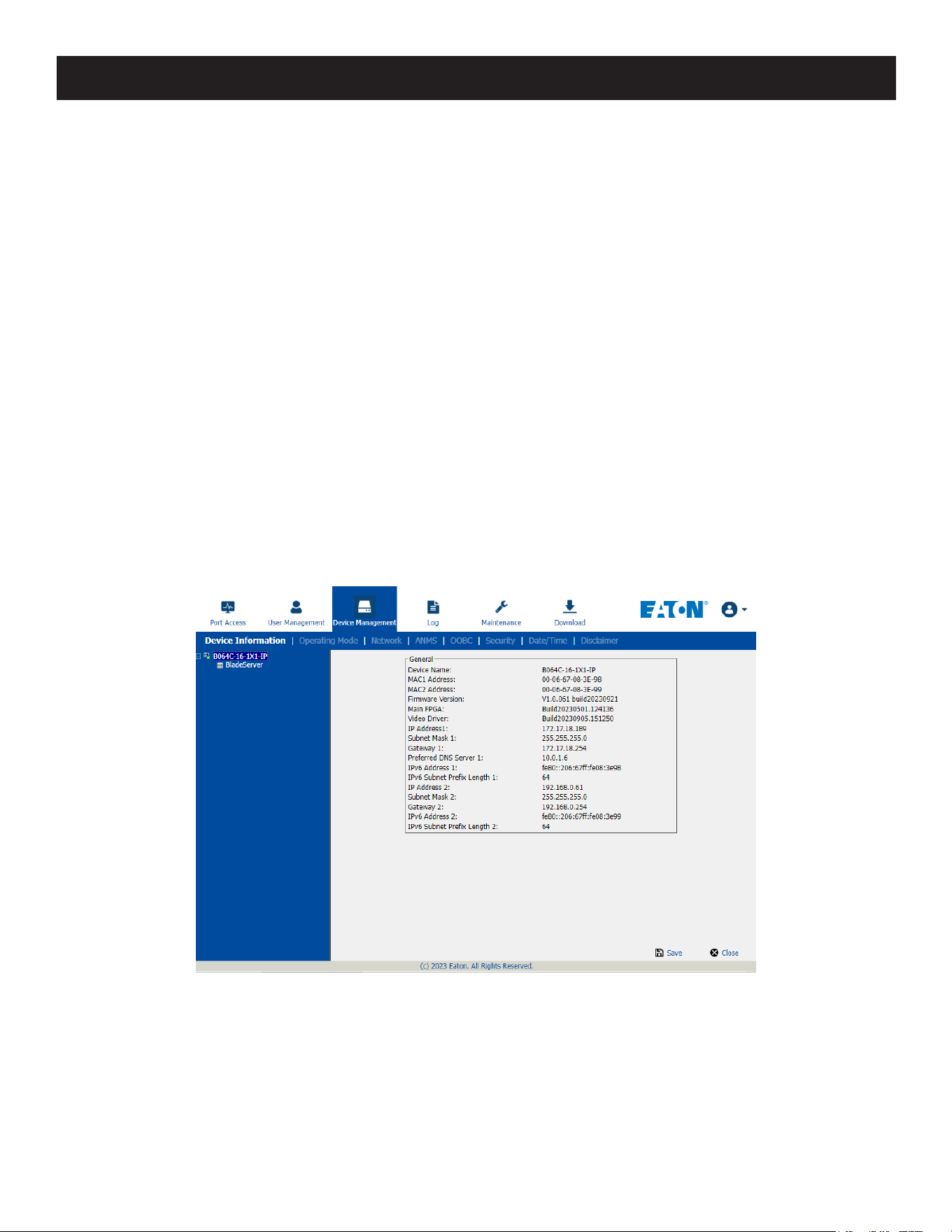
106
7. Administration
Assigning Device Permissions from the Groups’ Notebook
To assign device permissions to a Group of users, do the following:
1. In the Sidebar Groups list, click the group’s name.
– or –
In the main panel, select the group’s name.
2. Click Modify.
3. In the Groups notebook that appears, select the Devices tab.
4. The screen that appears is the same as in the User’s notebook. The only difference is that whatever settings you
make apply to all members of the group instead of just one individual member.
Make your device assignments according to the information described in Assigning Device Permissions from the
User’s Notebook.
7.7 Device Management
7.7.1 KVM Devices
Device Information
The Device Management page opens with the top level KVM over IP switch selected in the Sidebar and the Device
Information item selected on the menu bar:
Browser GUI
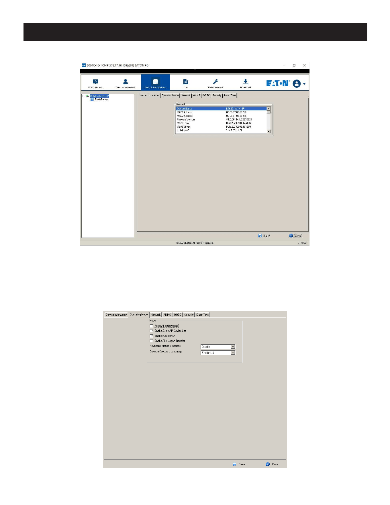
107
7. Administration
AP GUI
General
The General section of the Device Information page displays the name of the selected device, its firmware version, the
FPGA (Field-Programmable-Gate-Array) and information about its network configuration.
Note: The AP GUI version presents the same information as the Browser version. Scroll through the list to see the additional entries.
Operating Mode
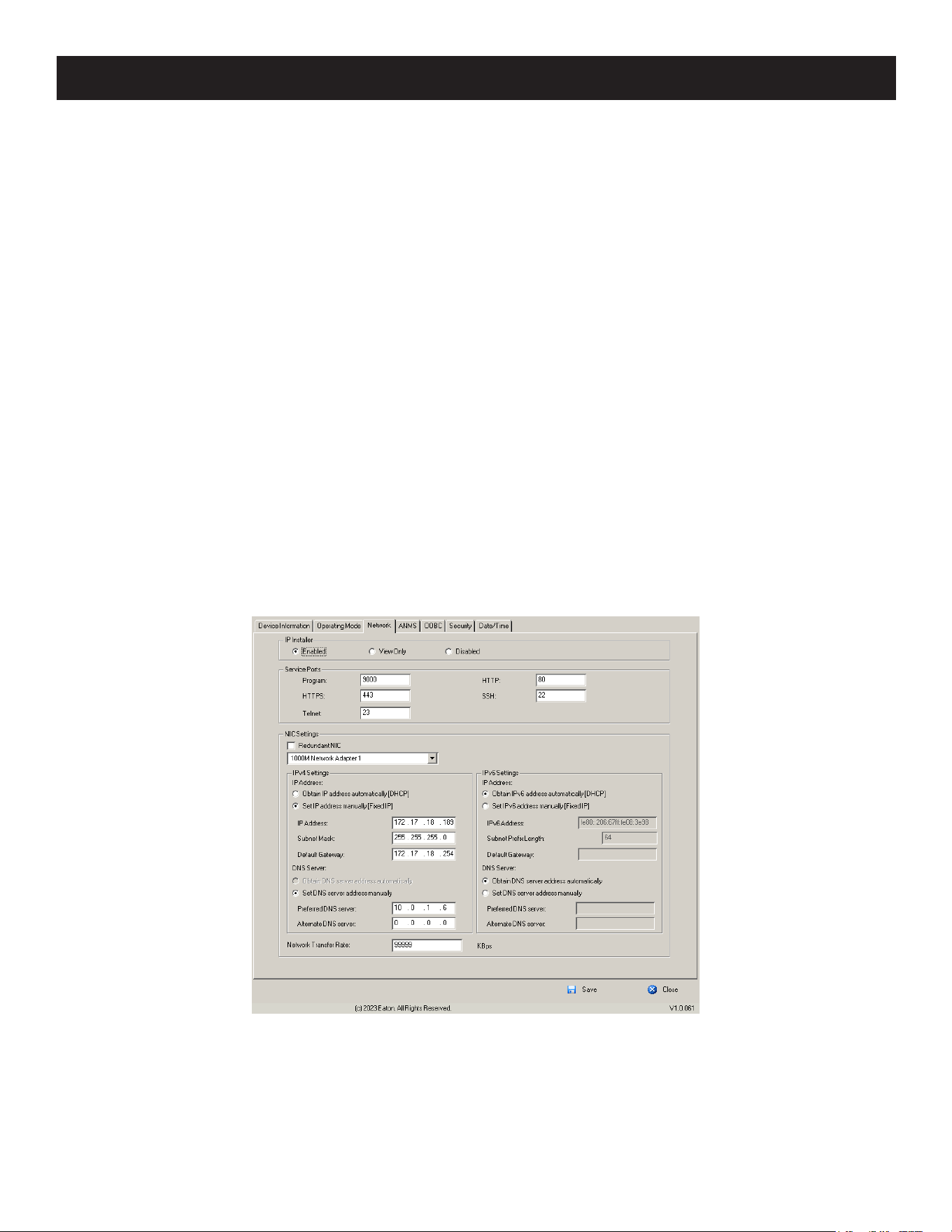
108
7. Administration
The Operating Mode page is used to set working parameters:
• If Force all to grayscale is enabled, the remote displays of all devices connected to the KVM over IP switch are changed
to grayscale. This can speed up I/O transfer in low bandwidth situations.
• If Enable Client AP Device List is enabled, the switch appears in the Server List when using the WinClient or Java Client
AP (see 7.3.3 Windows Client AP Login and 7.3.4 Java Client AP Login). If this option is not enabled, the switch
can still be connected. However, its name will not appear in the Server List.
• If Enable First Logon Transfer is enabled, only the first user on a bus can switch ports. Other users on the bus cannot
switch ports unless there is a bus that is already connected to the port they would like to access or there is a free bus
available.
o For Keyboard/Mouse Broadcast, use the drop-down list to make your choice.
• If you enable Keyboard Broadcast, your keystrokes will be duplicated on all the attached servers that currently
appear in the Sidebar.
• If you enable Mouse Broadcast, your mouse movements and clicks will be duplicated on all attached servers
currently in the Sidebar.
Notes:
• On a KVM switch that is cascaded from the KVM over IP switch, only one port can perform a Keyboard/Mouse broadcast at a
time.
• For Mouse Broadcast, you and all the servers must be running the same OS; all the monitors must have the same resolution; and
all the screens must have an identical layout.
• The Console Keyboard Language setting lets you specify which keyboard mapping is being used by the Local Console keyboard.
Use the drop-down list to make your choice.
Network
The Network page is used to specify the network environment.

109
7. Administration
IP Installer
The IP Installer is an external Windows-based utility for assigning IP addresses to the KVM over IP switch.
Click one of the radio buttons to select Enable, View Only or Disable for the IP Installer utility.
Notes:
• If you select View Only, you will be able to see the KVM over IP switch in the IP Installer’s Device List, but you will not be able to change the
IP address.
• For security, we strongly recommend you set this to View Only or Disable after each use.
Service Ports
As a security measure, if a firewall is being used, the Administrator can specify the port numbers that the firewall will
allow. If a port other than the default is used, users must specify the port number as part of the IP address when they
log in. If an invalid port number (or no port number) is specified, the KVM over IP switch will not be found. An
explanation of the fields is provided in the table below:
Field Explanation
Program
This is the port number for connecting with the WinClient ActiveX Viewer, WinClient AP,
Java Client Viewer, Java Client AP or via Virtual Media. The default is 9000.
HTTP The port number for a browser login. The default is 80.
HTTPS The port number for a secure browser login. The default is 443.
SSH The port for SSH access. The default is 22.
Telnet The port for Telnet access. The default is 23.
Notes:
• Valid entries for all service ports are from 1–65535.
• Service ports cannot have the same value. You must set a different value for each one.
• If there is no firewall (on an Intranet, for example), it does not matter what these numbers are set to since they have no effect.
NIC Settings
• Redundant NIC
The KVM over IP switch is designed with two network interfaces. If Redundant NIC is enabled (the default), both
interfaces make use of the IP address of Network Adapter 1.
Under this configuration, the second interface is usually inactive. If there is a network failure on the first interface, the
switch automatically switches to the second interface.
o Redundant NIC Enabled – Single IP Address for Both Interfaces To enable the Redundant NIC function, do the
following:
1. Click to put a check in the Redundant NIC checkbox.
2. Network Adapter 1 is selected in the network adapter listbox, and the listbox will be disabled (you cannot
configure Network Adapter 2).
3. Configure the IP and DNS server addresses for Network Adapter 1.
• Redundant NIC Not Enabled – Two IP Addresses
If you choose not to enable the Redundant NIC function, the two NICs can be configured with separate interfaces.
Users can log into the KVM over IP switch with either IP address. To set up the switch with this configuration, do the
following:
1. If there is a check in the Redundant NIC checkbox, click to remove it.
2. In the network adapter listbox, select Network Adapter 1.
3. Configure the IP and DNS server addresses for Network Adapter 1.
4. Use the drop-down to view the network adapter listbox and select Network Adapter 2.
5. Configure the IP and DNS server addresses for Network Adapter 2.

110
7. Administration
• IPv4 Settings
• IP Address
IPv4 is the traditional method of specifying IP addresses. The KVM over IP switch can either have its IP address
assigned dynamically (DHCP) or it can be given a fixed IP address.
o For dynamic IP address assignment, select the Obtain IP address automatically radio button (this is the default
setting).
o To specify a fixed IP address, select the Set IP address manually radio button and fill in the fields with values
appropriate for your network.
Notes:
• If you choose Obtain IP address automatically, when the switch starts up it will wait to obtain its IP address from the DHCP server.
If it has not obtained the address after one minute, it will automatically revert to its factory default IP address (192.168.0.60.).
• If the switch is on a network that uses DHCP to assign network addresses, and you need to ascertain its IP address.
• DNS Server
o For automatic DNS Server address assignment, select the Obtain DNS Server address automatically radio button.
o To specify the DNS Server address manually, select the Set DNS server address manually radio button and fill in
the addresses for the Preferred and Alternate DNS servers with values appropriate for your network.
Note: Specifying the Alternate DNS Server address is optional.
• IPv6 Settings
• IP Address
IPv6 is the new (128-bit) format for specifying IP addresses (see 7.1.1 IPv6 for more information). The KVM over IP
switch can either have its IPv6 address assigned dynamically (DHCP, or it can be given a fixed IP address.
o For dynamic IP address assignment, select the Obtain IP address automatically radio button (this is the default
setting).
o To specify a fixed IP address, select the Set IP address manually radio button and fill in the fields with values
appropriate for your network.
• DNS Server
o For automatic DNS Server address assignment, select the Obtain DNS Server address automatically radio button.
o To specify the DNS Server address manually, select the Set DNS server address manually radio button and fill in
the addresses for the Preferred and Alternate DNS servers with values appropriate for your network.
Note: Specifying the Alternate DNS Server address is optional.
Network Transfer Rate
This setting allows you to tailor the size of the data transfer stream to match network traffic conditions by setting the
rate at which the KVM over IP switch transfers data between itself and the client computers. The range is from 4–
99999 Kilobytes per second (KBps).
Finishing Up
After making any network changes, make sure to Reset on exit on the Device Management System Operation page has
been enabled (there is a check in the checkbox) before logging out. This allows network changes to take effect without
having to power the switch off and on.
ANMS
The ANMS (Advanced Network Management Settings) page is used to set up login authentication and authorization
management from external sources. It is organized as a notebook with two tabs, each with a series of related panels.
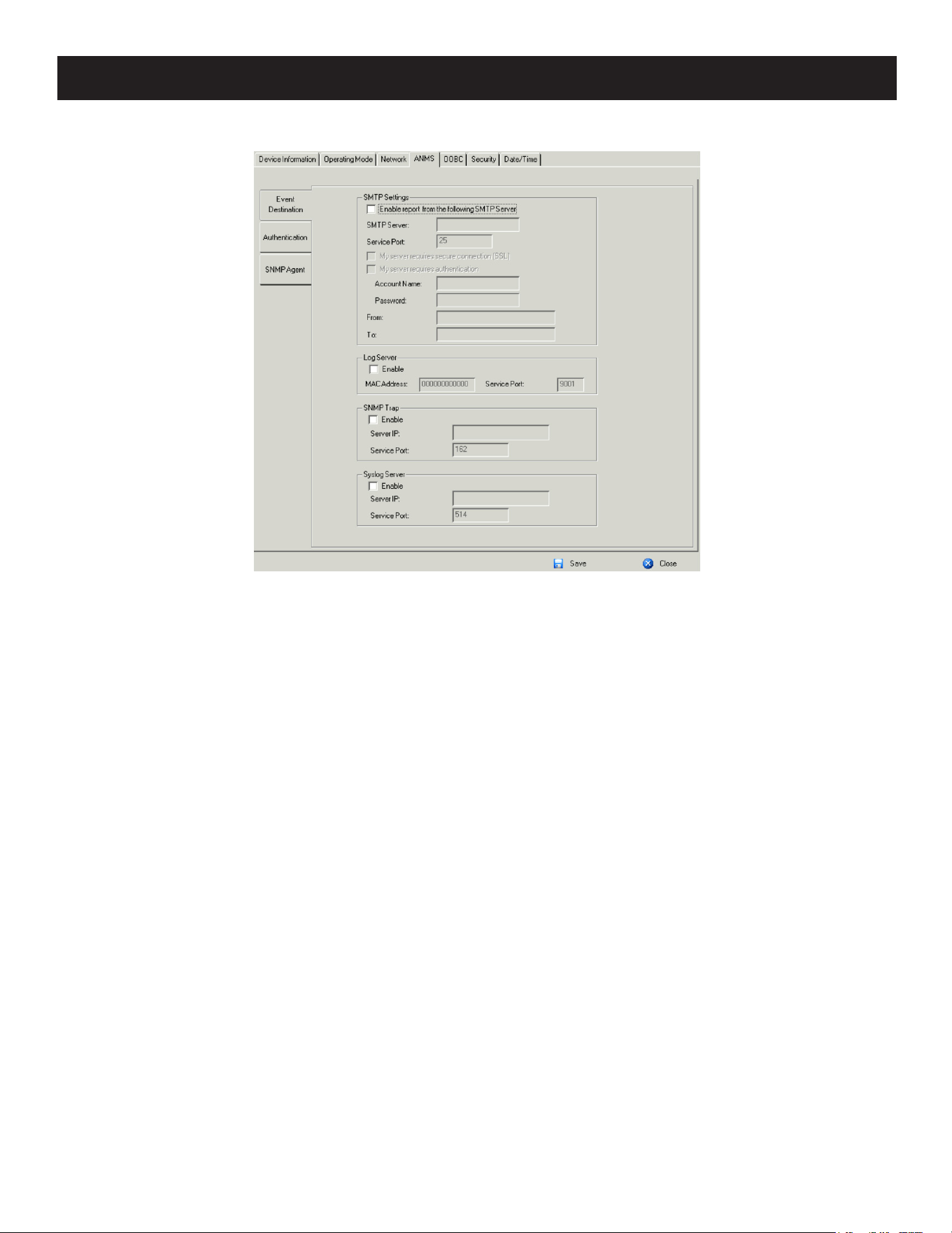
111
7. Administration
Event Destination
• SMTP Settings
To have the KVM over IP switch email reports from the SMTP server to you, do the following:
1. Enable the Enable report from the following SMTP server and key in either the IPv4 address, IPv6 address or domain
name of the SMTP server.
2. If your server requires a secure SSL connection, put a check in the My server requires secure connection (SSL)
checkbox.
3. If your server requires authentication, put a check in the My server requires authentication checkbox, and key in the
appropriate account information in the Account Name and Password fields.
4. Key in the email address from where the report is being sent in the From field.
Notes:
• Only one email address is allowed in the From field and it cannot exceed 64 Bytes.
• 1 Byte = 1 English alphanumeric character.
5. Key in the email address (addresses) of where you want the SMTP reports sent to in the To field.
Note: If you are sending the report to more than one email address, separate the addresses with a semicolon. The total cannot
exceed 256 Bytes.
• Log Server
Important transactions that occur on the KVM over IP switch such as logins and internal status messages are kept in
an automatically generated log file.
o Specify the MAC address of the computer that the Log Server runs on in the MAC address field.
o Specify the port used by the computer that the Log Server runs on to listen for log details in the Port field. The
valid port range is 1–65535. The default port number is 9001.
Note: The port number must be different than the one used for the Program port.
See 7.12 Log Server for details on setting up the log server.
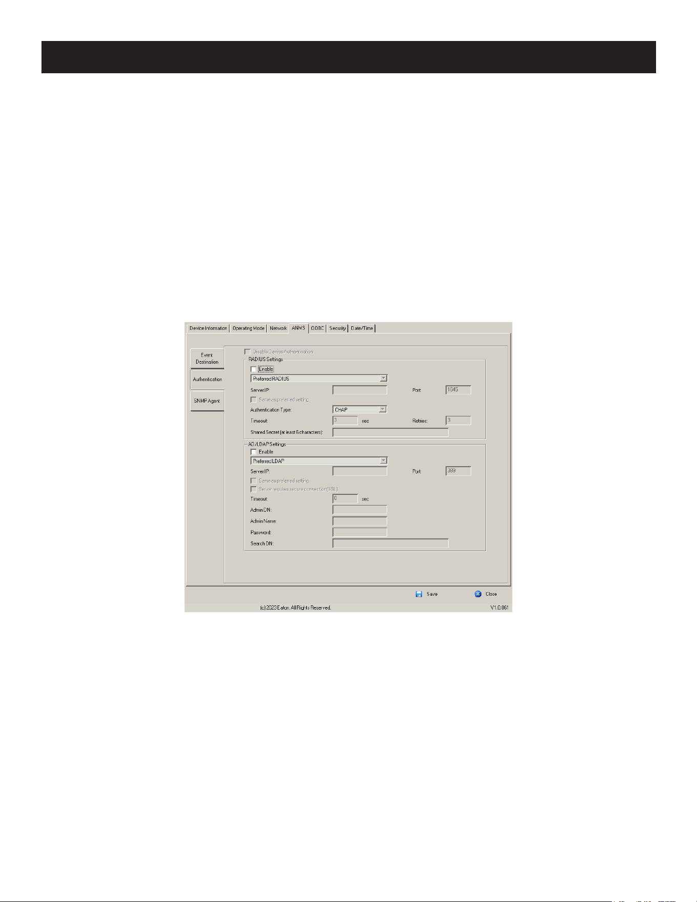
112
7. Administration
• SNMP Trap
To be notified of SNMP trap events:
1. Check Enable SNMP Agent.
2. Key in either the IPv4 address, IPv6 address, or domain name of the computer to be notified of SNMP trap events.
3. Key in the port number. The valid port range is 1–65535.
Note: The logs that are notified of SNMP trap events are configured on the Notification Settings page under the Log tab (see 7.8 Log
Notification Settings for details).
• Syslog Server
To record all the events that take place on KVM over IP switches and write them to a Syslog server:
1. Check Enable.
2. Key in either the IPv4 address, IPv6 address or domain name of the Syslog server.
3. Key in the port number. The valid port range is 1-65535.
Authentication
• Disable Local Authentication
Selecting this option disables login authentication on the KVM over IP switch. The switch can only be accessed using
LDAP, LDAPS, MS Active Directory, RADIUS or CC Management authentication.
• RADIUS Settings
To allow authentication and authorization for the KVM over IP switch through a RADIUS server:
1. Check Enable.
2. Select Preferred or Alternate RADIUS server.
3. Fill in the IP addresses and service port numbers for the Preferred and Alternate RADIUS servers. You can use the
IPv4 address, the IPv6 address or the domain name in the IP fields.
4. Select the Authentication Type.
5. In the Timeout field, set the time in seconds that the KVM over IP switch waits for a RADIUS server reply before it
times out.
6. In the Retries field, set the number of allowed RADIUS retries.

113
7. Administration
7. In the Shared Secret field, key in the character string that you want to use for authentication between the KVM over
IP switch and the RADIUS Server. A minimum of 6 characters is required.
8. On the RADIUS server, Users can be authenticated with any of the following methods:
o Set the entry for the user as su/xxxx
Where xxxx represents the Username given to the user when the account was created on the KVM over IP
switch.
o Use the same Username on both the RADIUS server and the KVM over IP switch.
o Use the same Group name on both the RADIUS server and the KVM over IP switch.
o Use the same Username/Group name on both the RADIUS server and the KVM over IP switch.
In each case, the user’s access rights are the ones assigned that were assigned when the User of Group was
created on the KVM over IP switch.
• LDAP / LDAPS Authentication and Authorization Settings
To allow authentication and authorization via LDAP or LDAPS, the Active Directory’s LDAP Schema must be extended
so that an extended attribute name for the B064C-16-1X1-IP – iKVM61-userProfile is added as an optional attribute to
the person class.
To manually find out the attribute name of the B064C-16-1X1-IP – iKVM61-userProfile, go to Terminal under
Maintenance and execute a get command (see 7.9.6 Terminal for details).
To configure the LDAP server:
1. Install the Windows Server Support Tools.
2. Install the Active Directory Schema Snap-in.
3. Extend and update the Active Directory Schema.
To allow authentication and authorization for the KVM over IP switch via LDAP / LDAPS, refer to the information in
the table below:
Item Action
Enable
Put a check in the Enable checkbox to allow LDAP / LDAPS authentication and
authorization.
Type Click a radio button to specify whether to use LDAP or LDAPS.
LDAP Server IP and Port
Select Preferred or Alternate LDAP Server and ll in the IP address and port number
for the LDAP or LDAPS server.
• You can use the IPv4 address, the IPv6 address or the domain name in the LDAP
Server eld.
• For LDAP, the default port number is 389; for LDAPS, the default port number is
636.
Admin DN
Consult the LDAP / LDAPS administrator to ascertain the appropriate entry for this
eld. For example, the entry might look like this:
ou=B064C161X1IP,dc=eaton,dc=com
Admin Name Key in the LDAP administrator’s username.
Password Key in the LDAP administrator’s password.
Search DN
Set the distinguished name of the search base. This is the domain name where the
search starts for user names.
Timeout
Set the time in seconds that the KVM over IP switch waits for an LDAP or LDAPS server
reply before it times out.
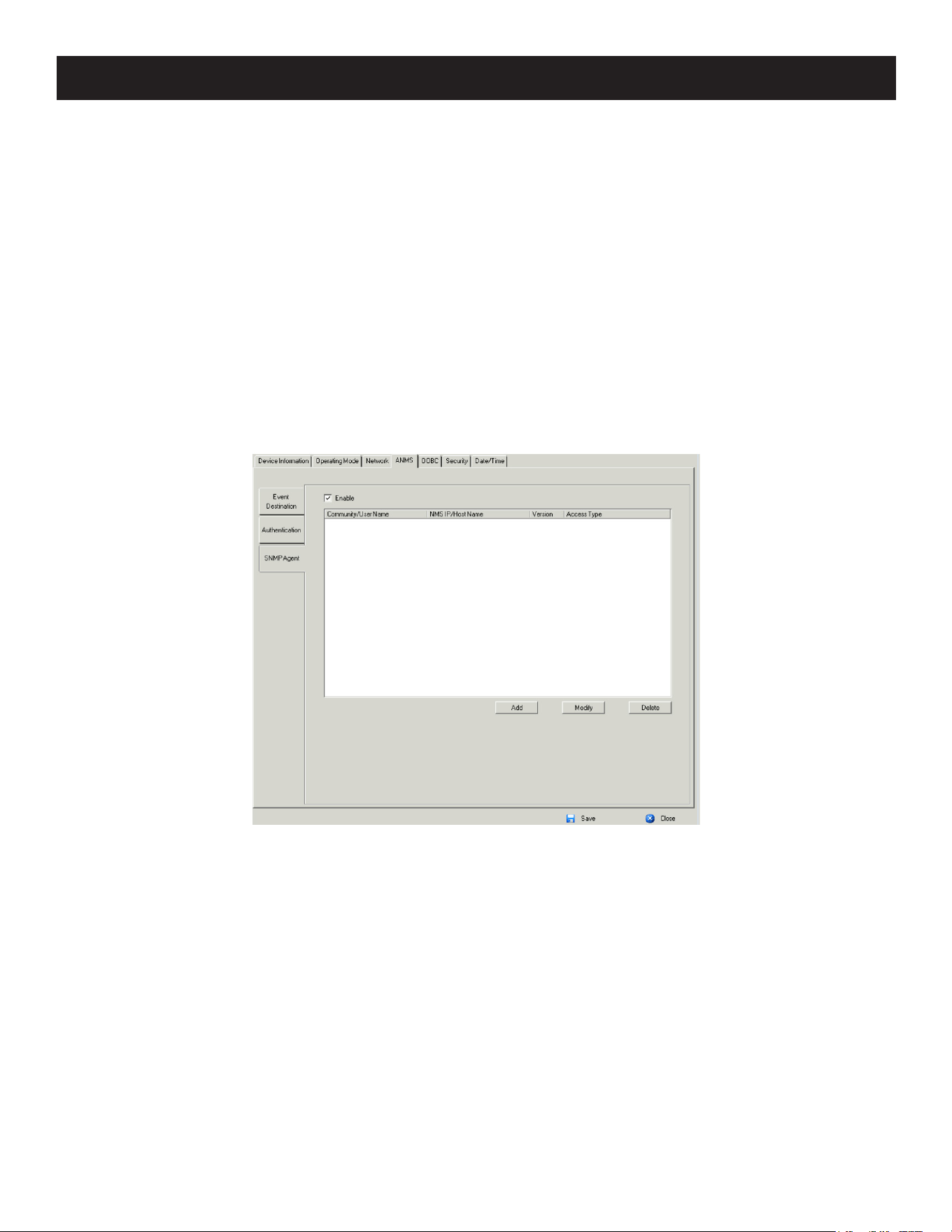
114
7. Administration
On the LDAP / LDAPS server, Users can be authenticated with any of the following methods:
• With MS Active Directory schema.
• Without schema – Only the Usernames used on the KVM over IP switch are matched to the names on the LDAP /
LDAPS server. User privileges are the same as the ones configured on the switch.
• Without schema – Only Groups in AD are matched. User privileges are the ones configured for the groups he belongs
to on the switch.
• Without schema – Usernames and Groups in AD are matched. User privileges are the ones configured for the User
and the Groups he belongs to on the switch.
SNMP Agent
The SNMP Agent allows you to configure Device Management settings with a MIB browser using the MIB file
downloaded from our website. The MIB file imports into the MIB browser to configure the following Device
Management settings: Operating Mode: Mode; Network: IP Installer, Service Ports, IPv4 Settings, IPv6 Settings; ANMS -
Event Destination: Log Server, SNMP Trap.
To connect to the switch through an MIB browser, use the instructions below to add an SNMP Agent to allow access
from the computer you will use to configure to the switch settings.
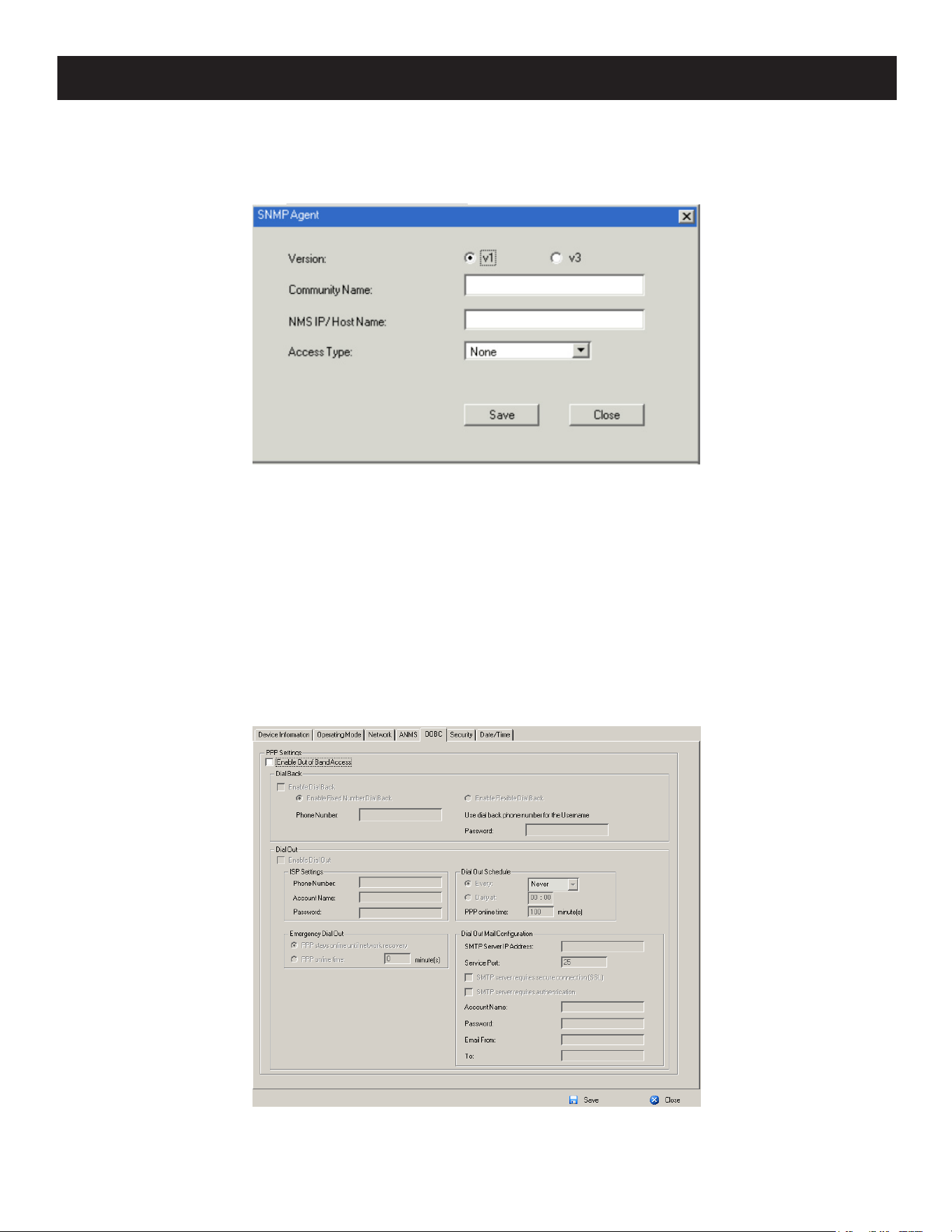
115
7. Administration
To add an SNMP Agent:
1. Check Enable.
2. Click Add. A window will appear:
3. Select the Version.
4. Enter a Community Name.
5. Key in NMS IP/Host Name. Enter the IP address of a computer that will access the switch via a MIB browser.
6. Select the Access Type and click Save.
7. From a MIB browser, import the MIB file and enter the IP address of the switch.
Note: Download the Eaton B064C MIB file on Eaton’s website from the B064C-16-1X1-IP product page.
OOBC
In case the KVM over IP switch cannot be accessed with the usual LAN-based methods, it can be accessed from the
switch’s modem port. To enable support for PPP (modem) operation, click to put a checkmark in the Enable Out of Band
Access checkbox.
When you enable Out of Band Access, the Enable Dial Back, and Enable Dial Out functions become available.

116
7. Administration
Enable Dial Back
As an added security feature, if this function is enabled the switch disconnects the calls that dial in to it and dials back
to one of the entries as specified in the table below:
Item Action
Enable Fixed Number Dial
Back
If Fixed Number Dial Back is enabled, when there is an incoming call, the KVM over IP
switch hangs up the modem and dials back to the modem whose phone number is
specied in the Phone Number eld.
Key the phone number of the modem that you want the KVM over IP switch to dial
back to in the Phone Number eld.
Enable Flexible Dial Back
If Flexible Dial Back is enabled, the modem that the KVM over IP switch dials back to
does not have to be xed. It can dial back to any modem that is convenient for the
user:
1. Key the password that the users must specify in the Password eld.
2. When connecting to the KVM over IP switch’s modem, users specify the phone
number of the modem that they want the KVM over IP switch to dial back to as their
Username and specify the password set in the Password eld for their password.
Enable Dial Out
For the dial out function, you must establish an account with an Internet Service Provider and use a modem to dial up
to your ISP account. An explanation of the Enable Dial Out items is provided in the table below:
Item Action
ISP Settings
Specify the telephone number, account name (username), and password that you use
to connect to your ISP.
Dial Out Schedule
This entry sets up the times you want the KVM over IP switch to dial out over the ISP
connection.
• Every provides a listing of xed times from every hour to every four hours.
o For example, if you select Every two hours, the KVM over IP switch will start dialing
out every two hours beginning at 00:00.
o If you do not want the KVM over IP switch to dial out on a xed schedule, select
Never from the list.
• Daily will dial out once a day at a specied time. Use the hh:mm format to specify the
time.
• PPP online time species how long you want the ISP connection to last before
terminating the session and hanging up the modem. A setting of zero means it is
always online.
Emergency Dial Out
If the KVM over IP switch gets disconnected from the network or the network goes
down, this function puts the switch online via the ISP dial up connection.
• If you choose PPP stays online until network recovery, the PPP connection to the ISP
will last until the network comes back up or the switch reconnects to it.
• If you choose PPP online time, the connection to the ISP will terminate after the
amount of time that you specify is up. A setting of zero means it is always online.
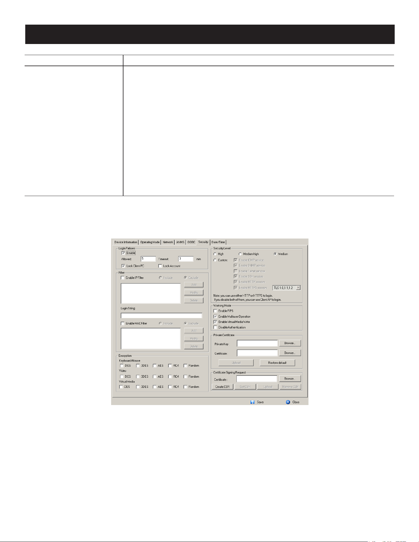
117
7. Administration
Item Action
Dial Out Mail Conguration
This section provides email notication of problems that occur on the devices
connected to the KVM over IP switch’s ports.
Note: This email notication diers from the one congured under SMTP Settings, in that it uses the
ISP mail server rather than the internal company’s mail server.
• Key in the IPv4 address, IPv6 address or domain name of your SMTP server in the
SMTP Server IP Address eld.
• Key in the email address of the person responsible for the SMTP server (or some
other equally responsible administrator) in the Email From eld.
• Key in the email address (addresses) of where you want the report sent to in the To
eld. If you are sending the report to more than one email address, separate the
addresses with a comma or a semicolon.
• If your server requires a secure SSL connection, put a check in the SMTP server
requires secure connection (SSL) checkbox.
• If your server requires authentication, put a check in the SMTP server requires
authentication checkbox, then key in the appropriate account name and password in
the elds.
Once you have finished making your settings on this page, click Save.
Security
The Security page is divided into 7 main panels.
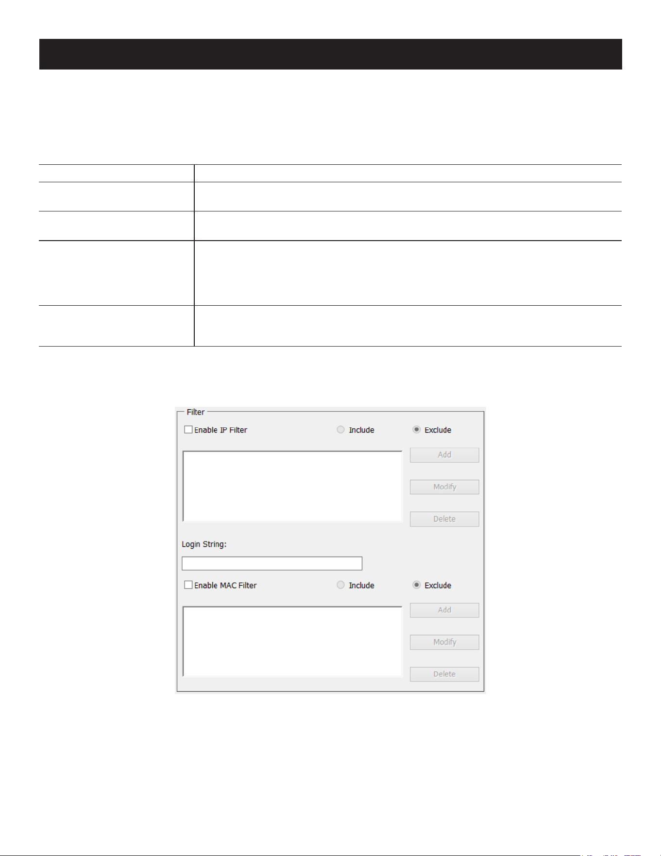
118
7. Administration
Login Failures
For increased security, the Login Failures section allows administrators to set policies governing what happens when a
user fails to log in successfully.
To set the Login Failures policy, check the Enable checkbox (the default is for Login Failures to be enabled). The
meanings of the entries are explained in the table below:
Entry Explanation
Allowed
Sets the number of consecutive failed login attempts that are permitted from a remote
computer. The default is 5 times.
Timeout
Sets the amount of time a remote computer must wait before attempting to login
again after it has exceeded the number of allowed failures. The default is 3 minutes.
Lock Client PC
If this is enabled, after the allowed number of failures have been exceeded, the
computer attempting to log in is automatically locked out. No logins from that
computer will be accepted. The default is enabled.
Note: This function relates to the client computer’s IP. If the IP is changed, the computer will no
longer be locked out.
Lock Account
If this is enabled, after the allowed number of failures have been exceeded, the user
attempting to log in is automatically locked out. No logins from the username and
password that have failed will be accepted. The default is enabled.
Note: If Login Failures is not enabled, users can attempt to log in an unlimited number of times with no restrictions. For security purposes,
we recommend that you enable this function and enable the lockout policies.
Filter
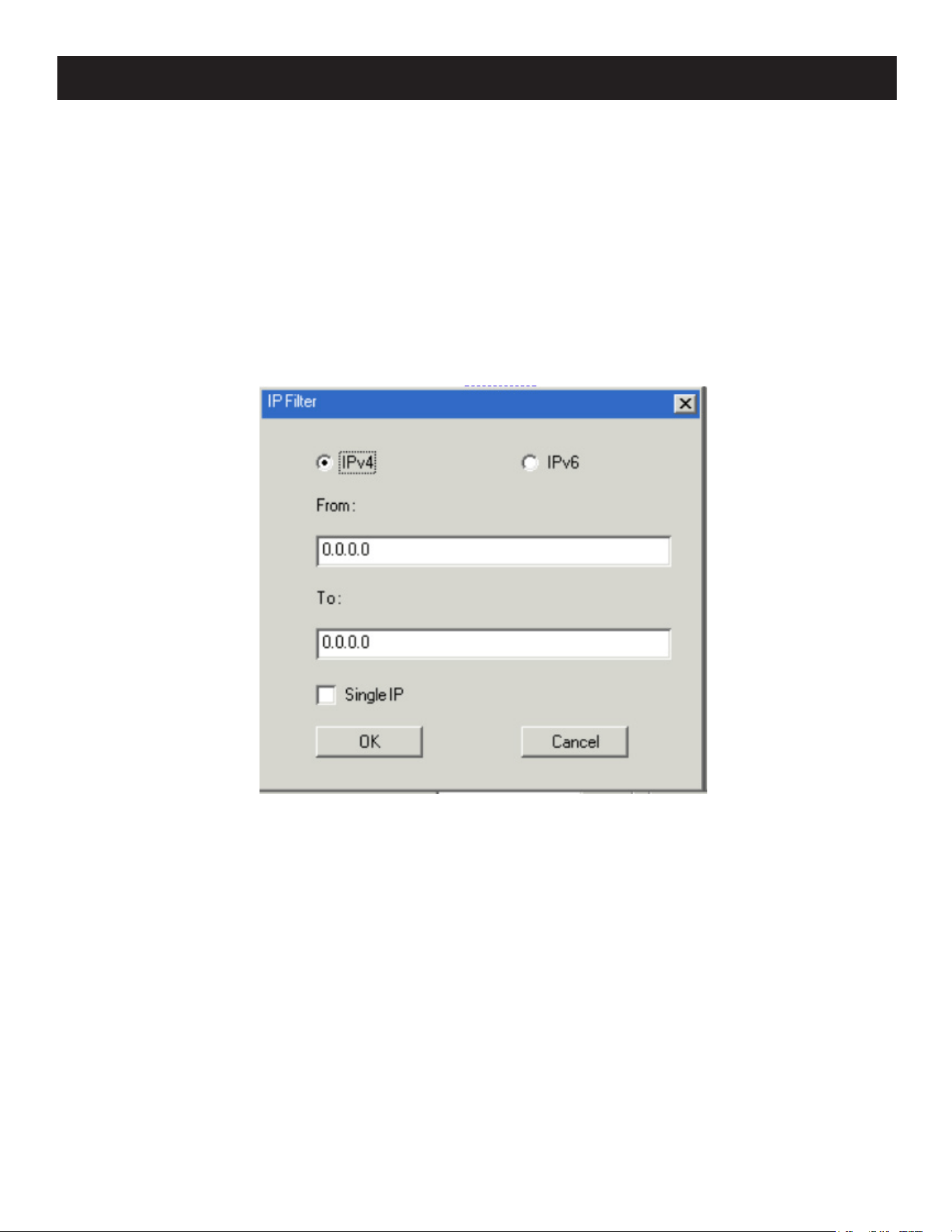
119
7. Administration
• IP and MAC Filtering
IP and MAC Filters control access to the KVM over IP switch based on the IP and/or MAC addresses of the client
computers attempting to connect. A maximum of 100 IP filters and 100 MAC filters are allowed. If any filters have
been configured, they appear in the IP Filter and/or MAC Filter list boxes.
To enable IP and/or MAC filtering, Click to put a check mark in the IP Filter Enable and/or MAC Filter Enable checkbox.
o If the include button is checked, all the addresses within the filter range are allowed access; all other addresses are
denied access.
o If the exclude button is checked, all the addresses within the filter range are denied access; all other addresses are
allowed access.
• Adding Filters
To add an IP filter:
1. Click Add. A dialog box similar to the one below appears:
2. Specify whether you are filtering an IPv4 or IPv6 address.
3. Key the address you want to filter in the From: field.
• To filter a single IP address, click to put a check in the Single IP checkbox.
• To filter a continuous range of addresses, key in the end number of the range in the To: field.
Notes: This description is for the AP GUI. The Browser GUI differs as follows:
• It does not offer an IPv4 or IPv6 choice. It only has From and To fields for IPv4 filtering.
• It does not have a checkbox to specify a single IP address. To filter a single IPv4 address, key the same address in both the From
and To fields.
4. After filling in the address, click OK.
5. Repeat these steps for any additional IP addresses you want to filter.
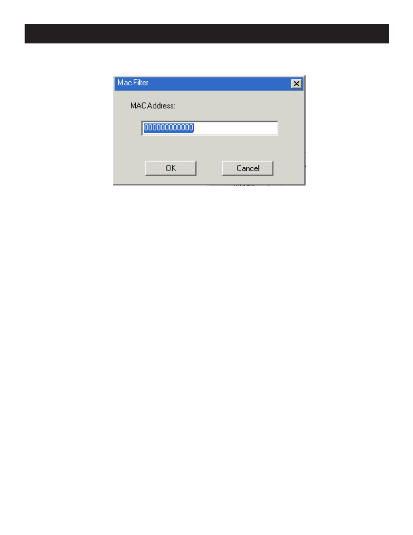
120
7. Administration
To add a MAC filter:
1. Click Add. A dialog box similar to the one below appears:
2. Specify the MAC address in the dialog box, then click OK.
3. Repeat these steps for any additional MAC addresses you want to filter.
• IP Filter / MAC Filter Conflict
If there is a conflict between an IP filter and a MAC filter (e.g., if a computer’s address is allowed by one filter but
blocked by the other), then the blocking filter takes precedence (the computer’s access is blocked).
• Modifying Filters
To modify a filter, select it in the IP Filter or MAC Filter list boxes and click Modify. The Modify dialog box is similar to
the Add dialog box. When it appears, simply delete the old address(es) and replace it with the new one(s).
• Deleting Filters
To delete a filter, select it in the IP Filter or MAC Filter list box and click Delete.
Login String
The Login String entry field lets the super administrator specify a login string (in addition to the IP address) that users
must add to the IP address when they access the KVM over IP switch with a browser.
For example, if 192.168.0.126 were the IP address, and abcdefg were the login string, then the user would have to key
in:
192.168.0.126/abcdefg
Notes:
• Users must place a forward slash between the IP address and the string.
• If no login string is specified here, anyone will be able to access the KVM over IP switch login page using the IP address alone. This makes
your installation less secure.
The following characters are allowed in the string: 0–9 a–z A–Z ~ ! @ $ & * ( ) _ - = + [ ] .
The following characters are not allowed:
% ^ ” : / ? # \ ‘ { } ; ’ < > [Space] Compound characters (É Ç ñ ... etc.)
For security purposes, we recommend you change this string occasionally.
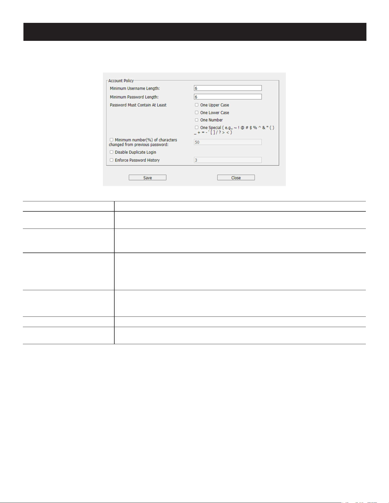
121
7. Administration
Account Policy
In the Account Policy section, system administrators can set policies governing usernames and passwords.
The meanings of the Account Policy entries are explained in the table below:
Entry Explanation
Minimum Username Length
Sets the minimum number of characters required for a username. Acceptable values
are from 1–16. The default is 6.
Minimum Password Length
Sets the minimum number of characters required for a password. Acceptable values
are from 0–32. A setting of 0 means that no password is required. Users can login with
only a Username. The default is 6.
Password Must Contain At
Least
Checking any of these items requires users to include at least one uppercase letter,
one lowercase letter or one number in their password.
Note: This policy only aects user accounts created after this policy has been enabled and
password changes to existing user accounts. For user accounts created before this policy is enabled,
there is no change to the existing passwords.
Minimum Number (%) of
Characters Changed from
Previous Password
Sets the minimum number in percentage of characters required to be changed from
the previous password.
Disable Duplicate Login Check this to prevent users from logging in with the same account at the same time.
Enforce Password History
Checking this box will require users to create a unique password that does not match
the last x passwords they have used. X equals the number entered in the dialog box.
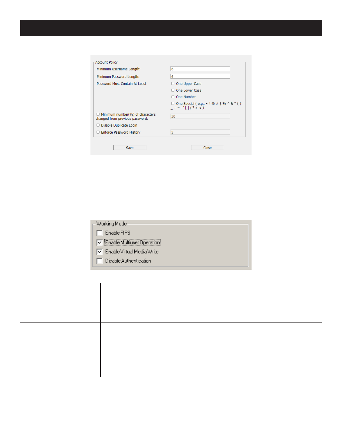
122
7. Administration
Encryption
These flexible encryption alternatives for keyboard/mouse, video and virtual media data let you choose any
combination of DES; 3DES; AES; RC4 or a Random cycle of any or all of them.
Enabling encryption affects system performance. No encryption offers the best performance and the greater the
encryption, the greater the adverse effect. If you enable encryption, the performance considerations are as follows:
• RC4 offers the least impact on performance; DES is next; then 3DES or AES
• The RC4 + DES combination offers the least impact of any combination.
Mode
An explanation of the Mode items is given in the table below:
Item Explanation
Enable FIPS Enables the FIPS security standard.
Enable Multiuser Operation
Enabling Multiuser operation permits up to 32 users to log in at the same time to
share the remote bus. If not enabled, only one user can log in at a time. The default is
Enabled.
Enable Virtual Media Write
Operation
Enabling Virtual Media Write Operation allows redirected virtual media devices on a
user’s system to send data to a remote server, as well as being able to have data from
the remote server written to them.
Disable Authentication
If Disable Authentication is checked, no authentication procedures are used to check
users attempting to log in. Users gain Administrator access to the KVM over IP switch
simply by entering combination of username and password.
Note: Enabling this setting creates an extremely dangerous result in terms of security and should
only be used only under special circumstances.
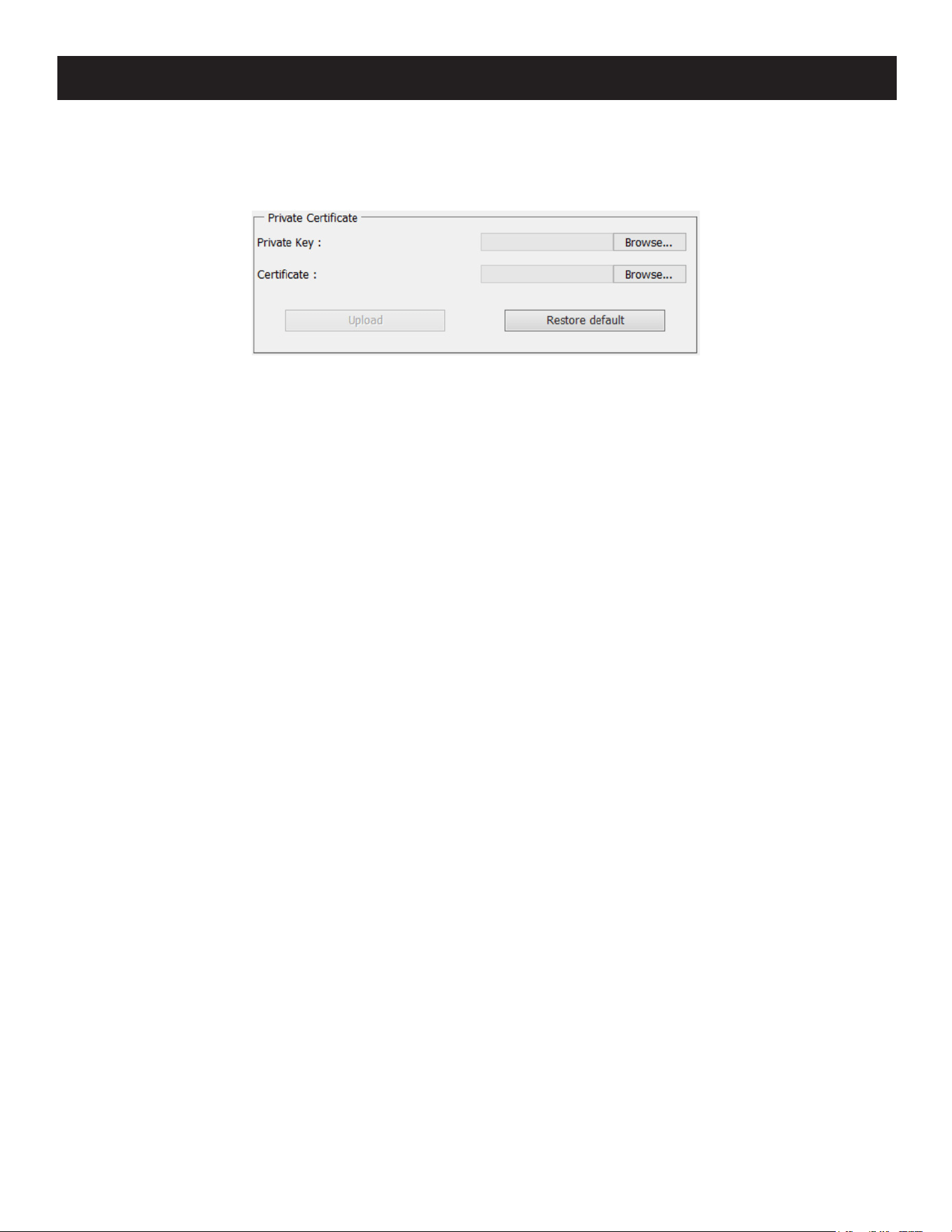
123
7. Administration
Private Certificate
When logging in over a secure (SSL) connection, a signed certificate is used to verify that the user is logging in to the
intended site. For enhanced security, the Private Certificate section allows you to use your own private encryption key
and signed certificate, rather than the default certificate.
There are two methods for establishing your private certificate: generating a self-signed certificate and importing a
third-party certificate authority (CA) signed certificate.
• Generating a Self-Signed Certificate
If you wish to create your own self-signed certificate, a free utility – openssl.exe – is available for download over the
web. See 7.1.3 Self-Signed Private Certificates for details about using OpenSSL to generate your own private key
and SSL certificate.
• Obtaining a CA Signed SSL Server Certificate
For the greatest security, we recommend using a third-party certificate authority (CA) signed certificate. To obtain a
third party signed certificate, go to a CA (Certificate Authority) website to apply for an SSL certificate. After the CA
sends you the certificate and private encryption key, save them to a convenient location on your computer.
• Importing the Private Certificate
To import the private certificate:
1. Click Browse to the right of Private Key, browse to where your private encryption key file is located and select it.
2. Click Browse to the right of Certificate, browse to where your certificate file is located and select it.
3. Click Upload to complete the procedure.
Notes:
• Clicking Restore Default returns the device to using the default certificate.
• Both the private encryption key and the signed certificate must be imported at the same time.
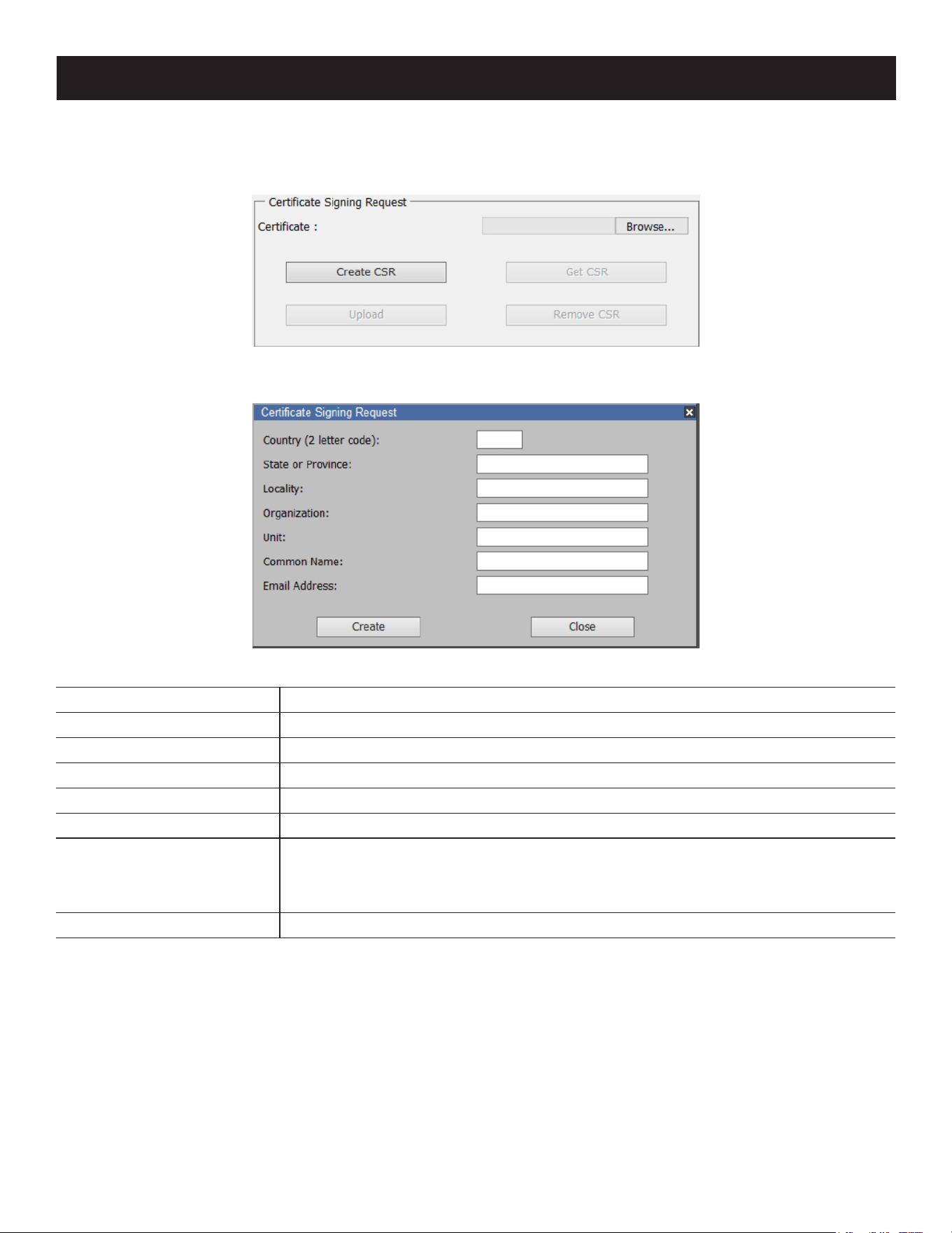
124
7. Administration
Certificate Signing Request
The Certificate Signing Request (CSR) section provides an automated way of obtaining and installing a CA signed SSL
server certificate.
To perform this operation:
1. Click Create CSR. The following dialog box will appear:
2. Fill in the form with entries that are valid for your site. Example information is provided in the following table:
Information Example
Country (2 letter code) US
State or Province IL
Locality US
Organization Your Company, Ltd.
Unit Techdoc Department
Common Name
mycompany.com
Note: This must be the exact domain name of the site that you want the certicate to be valid
for. If the site’s domain name is www.mycompany.com, and you only specify mycompany.com, the
certicate will not be valid.
Email Address [email protected]
3. After filling in the form (all fields are required), click Create.
A self-signed certificate based on the information you just provided will now be stored on the KVM over IP switch.
4. Click Get CSR and save the certificate file (csr.cer) to a convenient location on your computer.
This is the file that you give to the third-party CA to apply for their signed SSL certificate.
5. After the CA sends you the certificate, save it to a convenient location on your computer. Click Browse to locate the
file, then click Upload to store it on the KVM over IP switch.
Note: Once you upload the file, the KVM over IP switch will check the file to make sure the specified information still matches. If it does,
the file is accepted; if not, it is rejected.
If you want to remove the certificate (to replace it with a new one because of a domain name change, for example),
simply click Remove CSR.
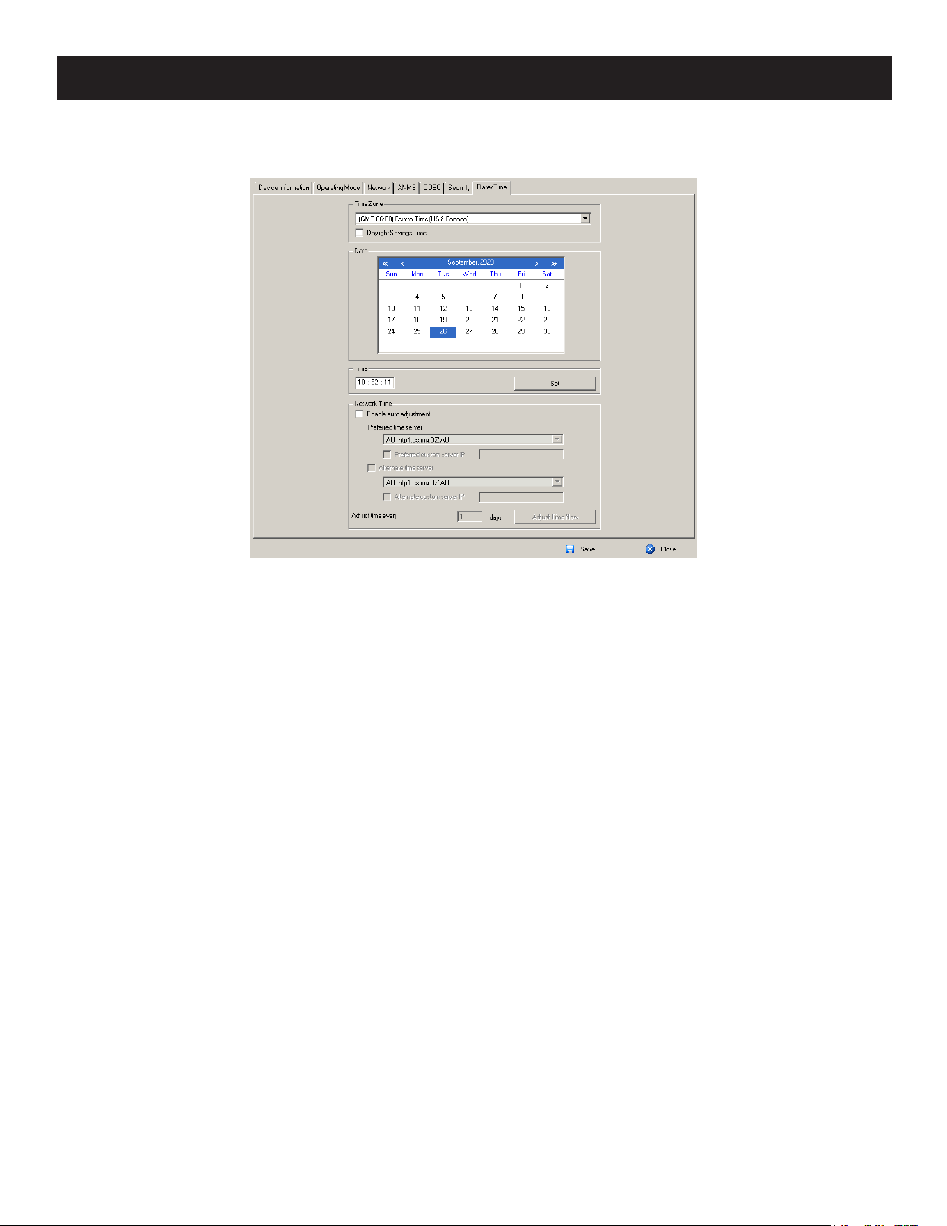
125
7. Administration
Date/Time
The Date/Time dialog page sets the KVM over IP switch time parameters:
Set the parameters according to the information below.
Time Zone
• To establish the time zone where the KVM over IP switch is located, use the drop-down to view the Time Zone list and
choose the city that most closely corresponds to where it is at.
• If your country or region employs Daylight Saving Time (Summer Time), check the corresponding checkbox.
Date
• Select the month from the drop-down listbox.
• Click < or > to move backward or forward by one-year increments.
• In the calendar, click on the day.
• To set the time, use the 24 hour HH:MM:SS format.
• Click Set to save your settings.
Network Time
To have the time automatically synchronized to a network time server:
1. Check the Enable auto adjustment checkbox.
2. Drop down the time server list to select your preferred time server
– or –
Check the Preferred custom server IP checkbox and key in either the IPv4 address, IPv6 address or domain name of
the time server of your choice.
3. If you want to configure an alternate time server, check the Alternate time server checkbox and repeat step 2 for the
alternate time server entries.
4. Key in your choice for the number of days between synchronization procedures.
5. If you want to synchronize immediately, click Adjust Time Now.
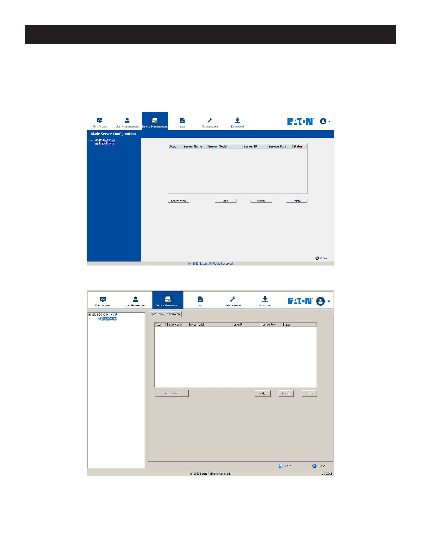
126
7. Administration
7.7.2 Blade Servers
Configuration Page
For Super Administrators, when a Blade Server is selected in the Sidebar, its Configuration page will appear:
Browser GUI
AP GUI
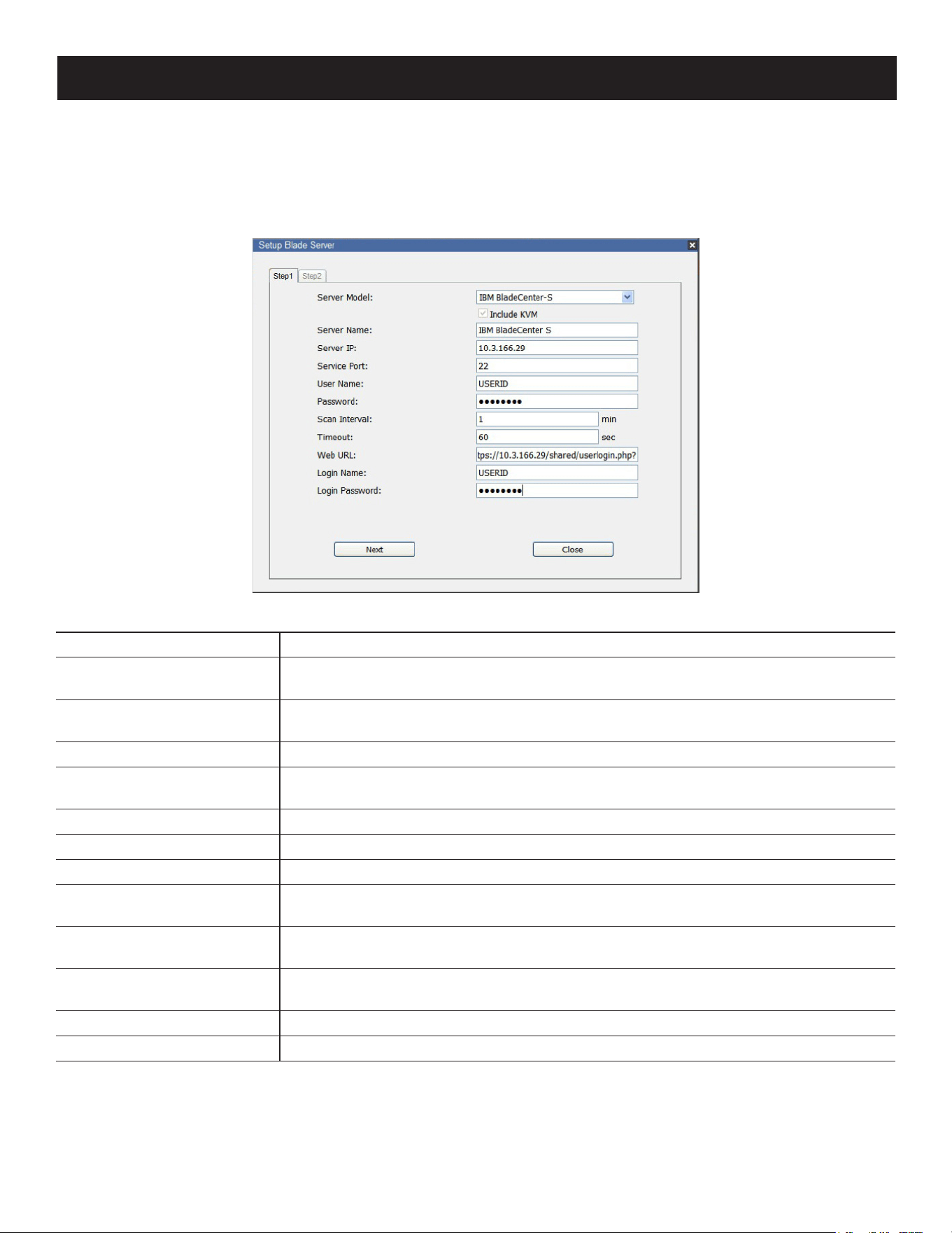
127
7. Administration
Blade Server Setup
Adding a Blade Server
1. Select its icon in the Sidebar, then click Add in the main panel. The Setup Blade Server dialog box appears with the
Step 1 tab displayed:
2. Fill in the fields according to the information provided in the table below:
Field Explanation
Server Model
Drop down the list to select the blade server chassis model. If your model is not
included in the list of supported servers, contact your dealer for help.
Include KVM
This item is for information purposes and cannot be edited. If the server supports a
KVM function, this box is checked. Otherwise, it is unchecked.
Server Name For convenience, you can give the server a name.
Server IP
Key in the server’s IP address (IPv4, IPv6, or domain name) used to access the server
via a serial connection (Telnet or SSH).
Service Port Key in the port number used for serial access.
User Name Key in the username required for serial access authentication.
Password Key in the password required for serial access authentication.
Scan Interval
The interval between times that the KVM over IP switch scans the server for
information.
Timeout
The amount of time that the KVM over IP switch waits for a response from the server
before it stops scanning for information.
Web URL
Key in the server’s IP address (IPv4, IPv6, or domain name) used to access the server
via a browser.
Login Name Key in the username required for browser authentication.
Login Password Key in the password required for browser authentication.
3. When you have finished configuring the fields, click Next to open the dialog box with the Step 2 tab displayed.
4. The Step 2 dialog presents a summary of the blade server’s configuration, including the number of blades installed.
Click Save to add the blade server to the installation.
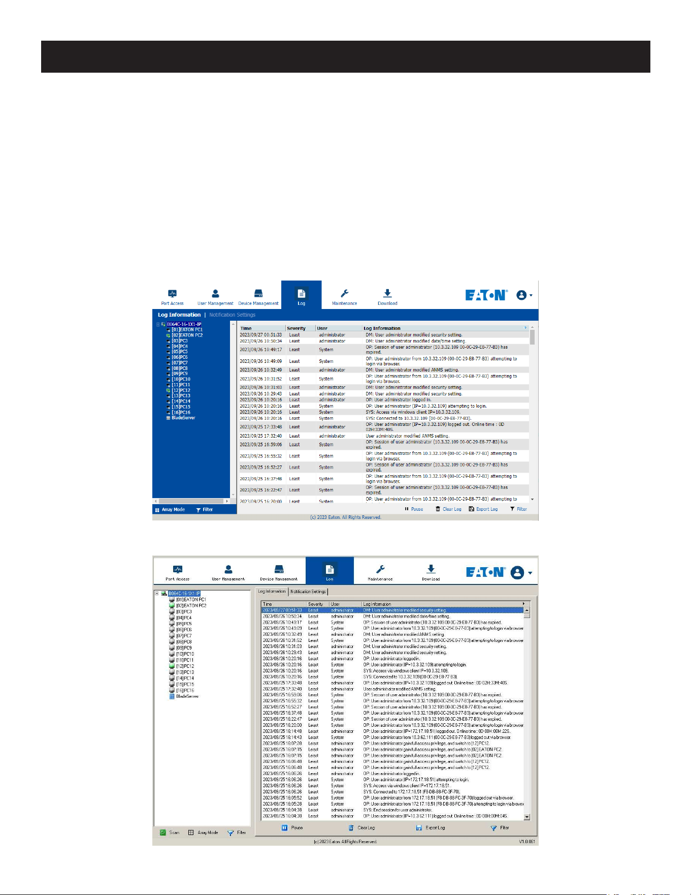
128
7. Administration
Modifying / Deleting a Blade Server
• To modify a blade server’s configuration, select it in the Sidebar, then click Modify. Make your changes on the Setup
Blade Server dialog box.
• To remove a blade server, select it in the Sidebar, then click Delete.
Web Access
To access the blade server’s Web page, select it in the Sidebar, then click Access Web.
7.8 Log
The KVM over IP switch logs all the events that take place on it. To view the contents of the log, click the Log tab.
Browser GUI
AP GUI
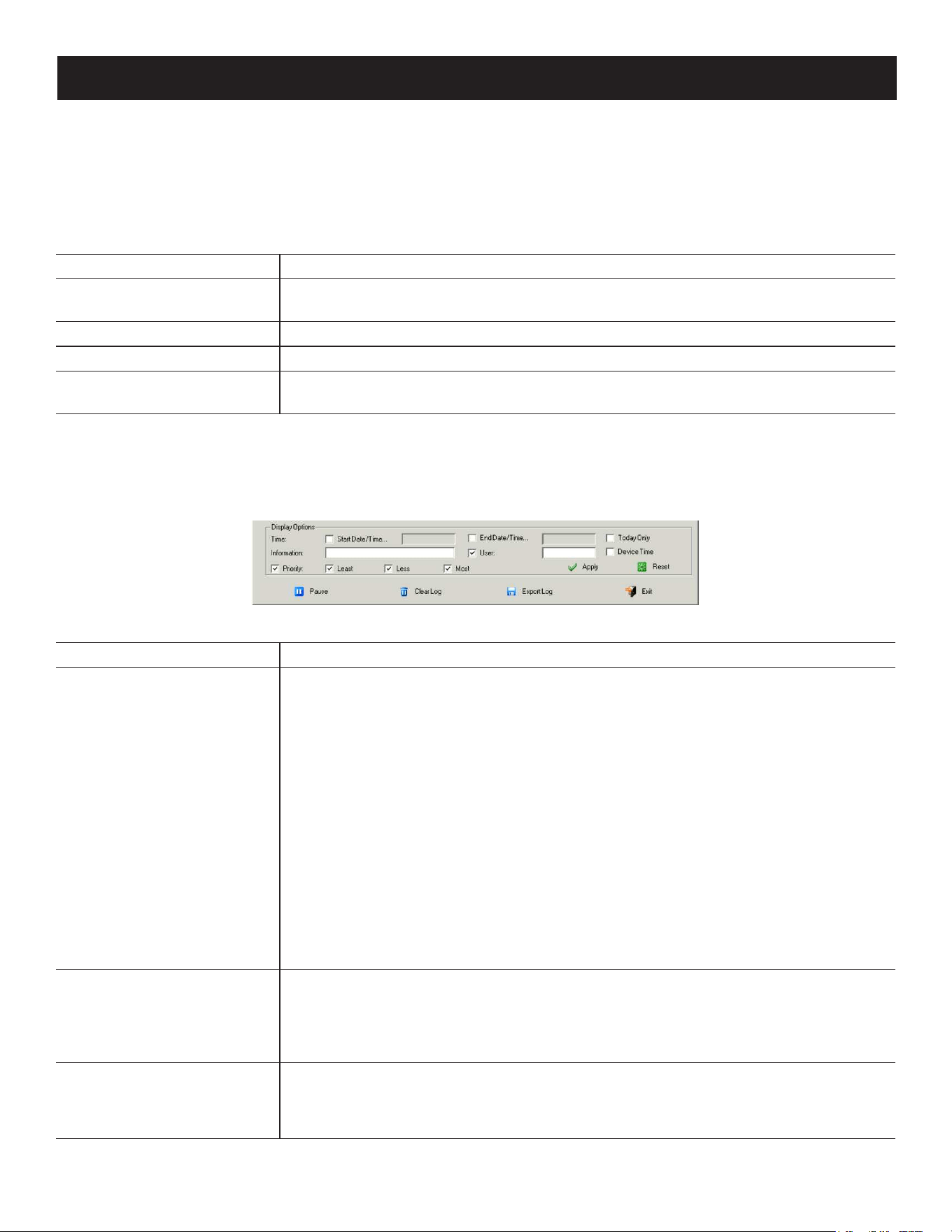
129
7. Administration
7.8.1 Log Information
The Log Information page displays events that take place on the B064C-16-1X1-IP and provides a breakdown of the
time, the severity, the user, and a description of each one. You can change the sort order of the display by clicking on
the column headings.
The log file tracks a maximum of 512 events. When the limit is reached, the oldest events get discarded as new events
come in. The purpose of the buttons at the bottom of the page are described in the following table:
Button Explanation
Pause
Clicking Pause stops the display of new events. When the display is paused, the button
changes to Resume. Click Resume to start displaying events again.
Clear Log Clicking Clear Log clears the log le.
Export Log Clicking Export Log lets you save the contents of the log to a le on your computer.
Filter
Clicking Filter allows you to search for particular events by date or by specic words or
strings.
Filter
Filter lets you narrow the log event display to ones that occurred at specific times, ones containing specific words or
string or ones involving specific users. When you access this function, the log filter dialog box appears at the bottom of
the page:
A description of the filter items is provided in the table below:
Item Description
Time
This feature lets you lter for events that occurred at specic times.
Today Only: Only the events for the current day are displayed.
Device Time: Shows the events according to the time congured on the switch.
Start Date/Time: Filters for events from a specic date and time to the present. Put
a check in the checkbox to open a calendar. Set the date and time that you want the
ltering to start from. All events from the Start Date/Time to the present are displayed.
For the Web Browser interface, after checking Start Date/Time, click inside the text box
to open the calendar.
Once you have made your calendar choices, click the A icon at the lower right of the
calendar panel.
End Date/Time: Filters for events from a specic date and time to a specic date and
time. First select the Start Date/Time (described above), then check End Date/Time to
set the ending date and time.
For the Web Browser interface, after checking End Date/Time, you click inside the text
box to open the calendar. Once you have made your calendar choices, click the A icon
at the lower right of the calendar panel.
Information
Filters for a particular word or string. Key the word or string into the Information text
box. Only events containing that word or string are displayed. Wildcards (? for single
characters; * for multiple characters) and the keyword or are supported. For example,
h*ds would return ”hands” and “hoods”, h?nd would return “hand” and “hind”, but not
“hard” and h*ds or h*ks would return “hands” and “hooks”.
User
Filters for specic users. First put a check in the User checkbox, key in the user’s
Username, then click Apply. Only events containing that Username are displayed.
Note: If the User checkbox is not checked here in the Filter panel, the entire User column does not
appear in the main panel.
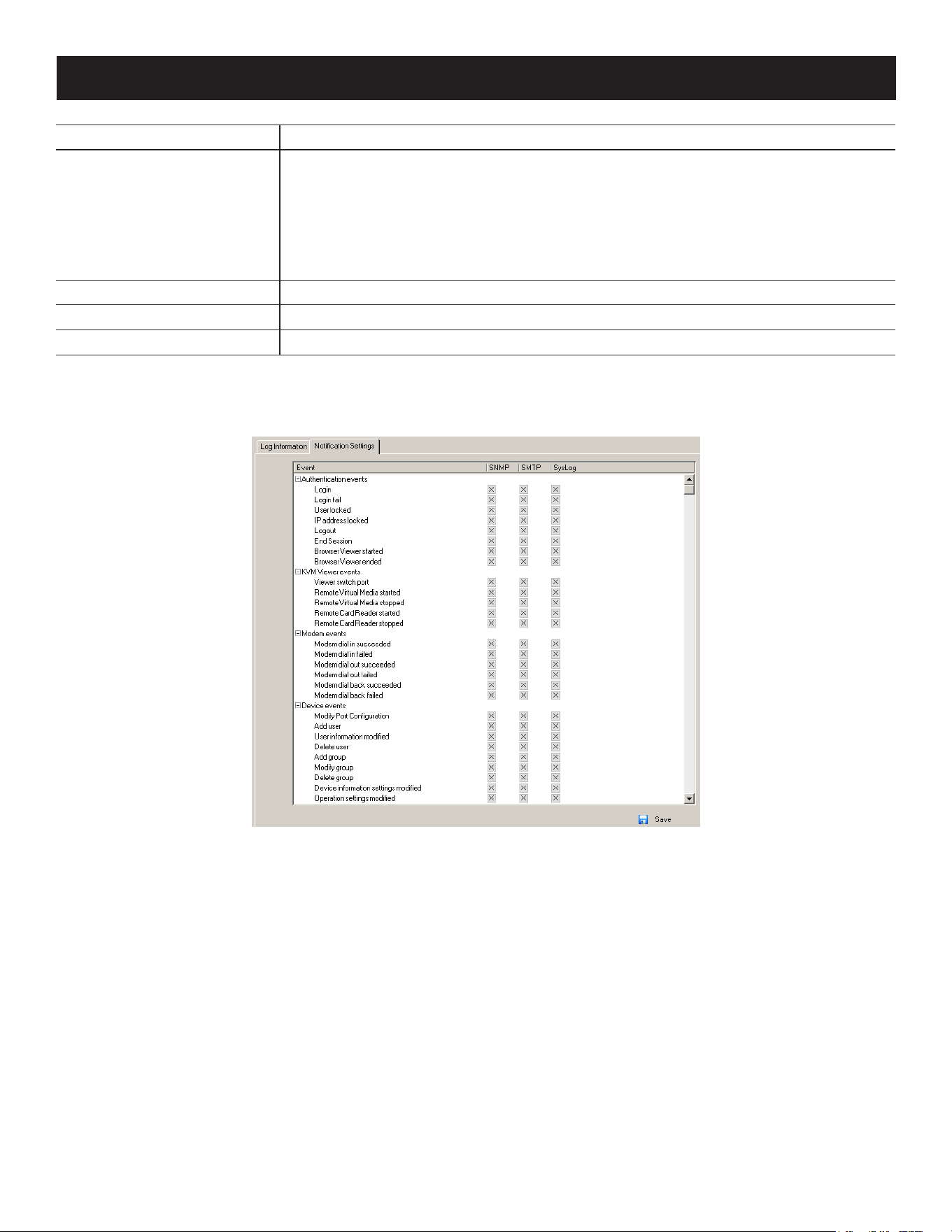
130
7. Administration
Item Description
Severity
Filters based on the severity rating of the event. Least events appear in black, less
events appear in blue and most events appear in red.
First put a check in the Severity checkbox, then check the severity options you want
to lter for (you can check more than one item). Only events that match the severity
ratings you specied appear in the display.
Note: If the Severity checkbox is not checked here in the Filter panel, the entire Severity column does
not appear in the main panel.
Apply Click to apply the lter choices.
Reset Click this button to clear the entries in the dialog box and start new.
Exit Click this button to exit the log lter function.
7.8.2 Log Notification Settings
The Notification Settings page lets you decide which events trigger a notification and how the notification are sent:
Notifications can be sent via SNMP trap, SMTP email, written to the SysLog file, or any combination of the three. A check
mark (√) indicates that notification of the event is enabled for the method specified in the column heading and an X
indicates that notification is not enabled.
Note: In any of the columns, you can use Shift-Click or Ctrl-Click to select a group of events. Clicking to enable/disable any one of them will
cause all of them to change in unison.
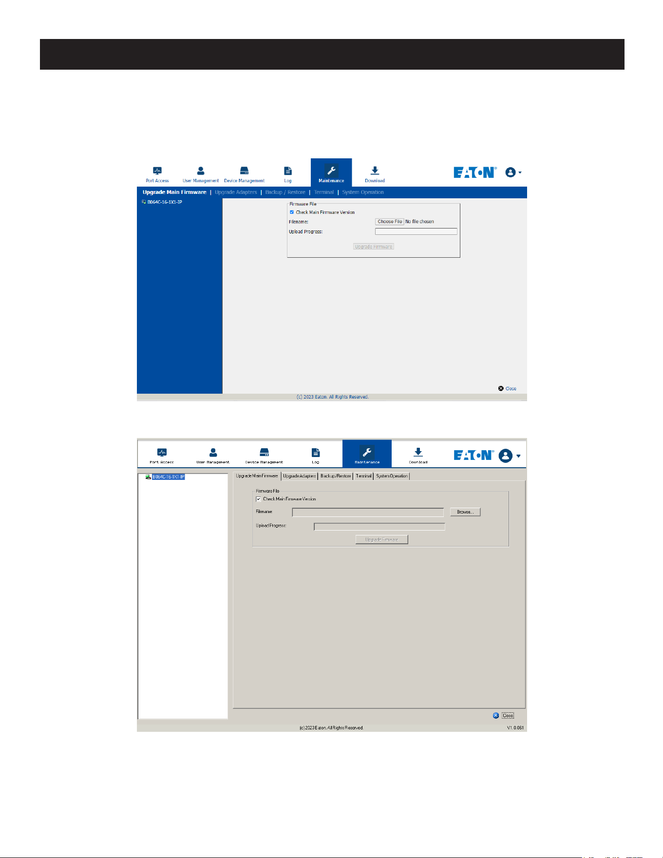
131
7. Administration
7.9 Maintenance
The Maintenance function is used to upgrade firmware, backup and restore configuration and account information, ping
network devices, and restore default values.
Browser GUI
AP GUI
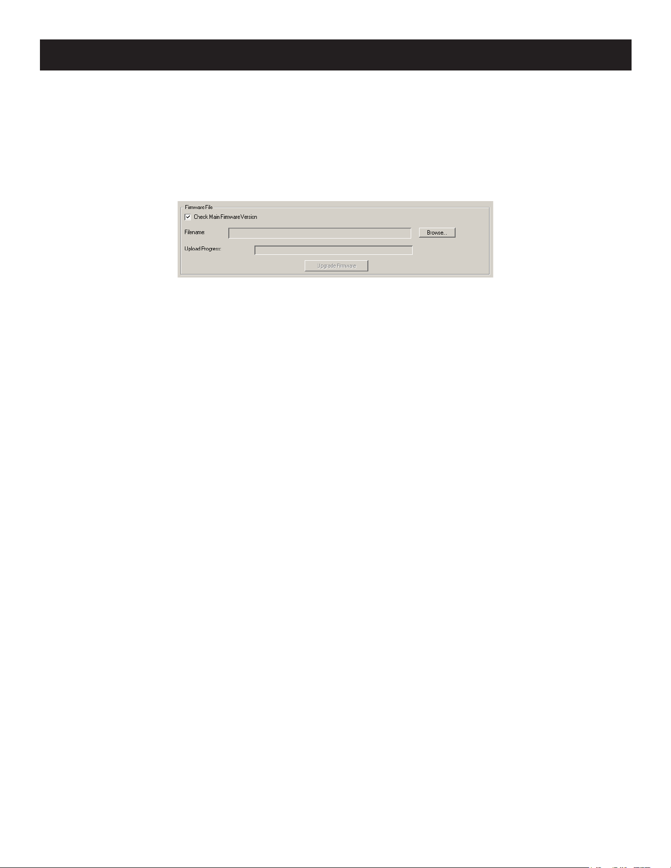
132
7. Administration
7.9.1 Main Firmware Upgrade
As new versions of the firmware become available, they can be downloaded from tripplite.eaton.com/products/
management-firmware-matrix. Check the website regularly to find the latest information and packages.
To upgrade the main firmware:
1. Download the new firmware file to your computer.
2. Log in to the KVM over IP switch; and click the Maintenance tab. The Maintenance tab opens to the Upgrade Main
Firmware page:
3. Click Browse, navigate to the directory the new firmware file is in and select the file.
4. Click Upgrade Firmware to start the upgrade procedure.
• If you enabled Check Main Firmware Version, the current firmware level is compared with that of the upgrade file. If
the current version is equal to or higher than the upgrade version, a popup message appears to inform you of the
situation and stop the upgrade procedure.
• If you did not enable Check Main Firmware Version, the upgrade file is installed without checking what its level is.
• As the upgrade proceeds, progress information is shown in the Progress bar.
• Once the upgrade completes successfully, the switch will reset.
5. Log in again and check the firmware version to be sure it is the new one.
7.9.2 Recovering from Failed Firmware Upgrade
Should the switch’s main firmware upgrade procedure fail and the switch becomes unusable, follow these steps to
resolve the problem:
1. Power off the switch.
2. Press and hold the reset button.
3. While holding the reset button, power the switch back on.
This will cause the switch to use the original factory installed main firmware version. Once the switch is operational, you
can try upgrading the main firmware again by logging on to the KVM over IP switch via web browser (see 7.9.1 Main
Firmware Upgrade).
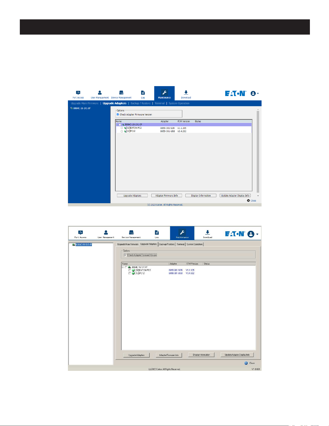
133
7. Administration
7.9.3 Upgrade Adapters
The Upgrade Adapters page allows you to view and update KVM adapter firmware and display information. This section
refers to the KVM adapter cables that provide the EDID display information to the connected server, which allow its
video to be displayed on the local console monitor.
Browser GUI
AP GUI
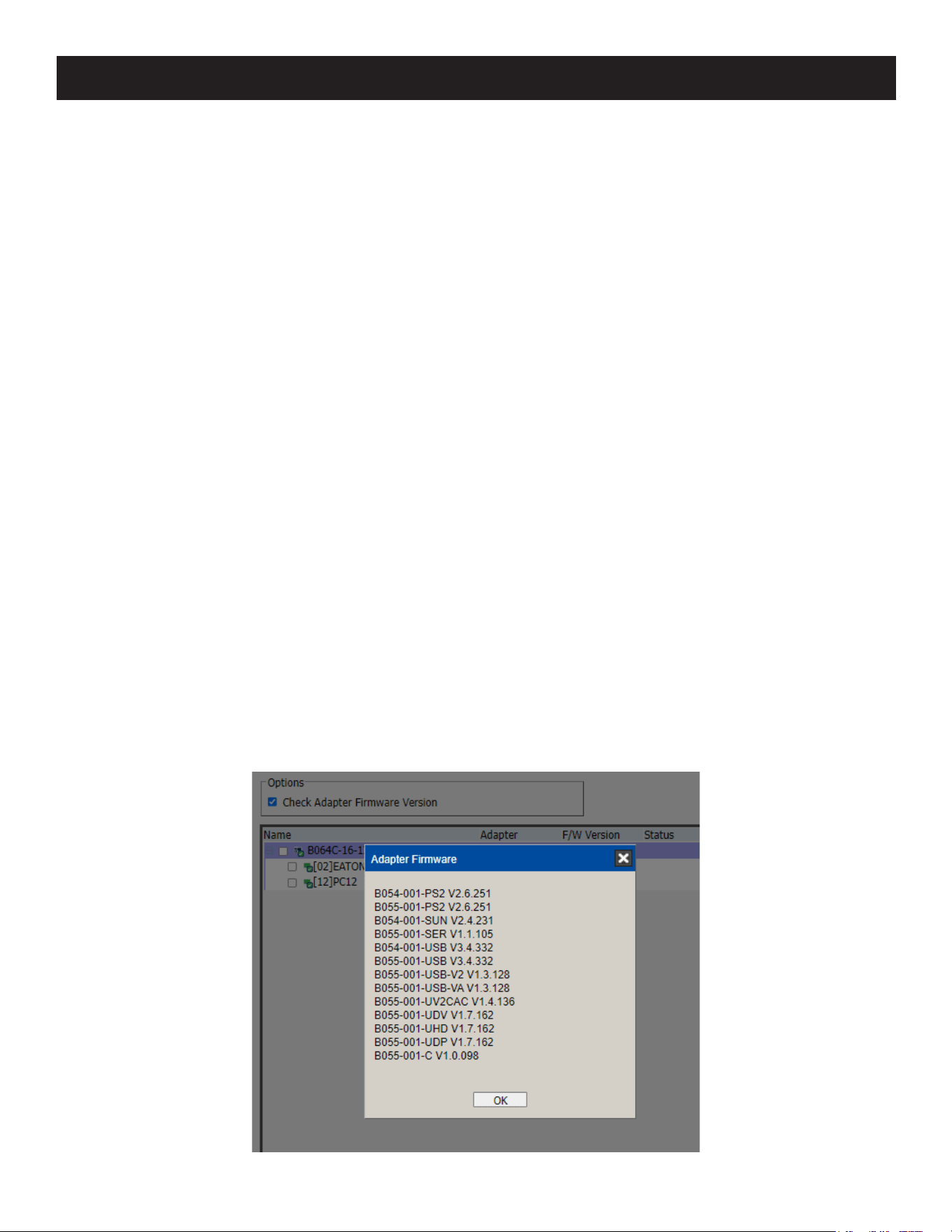
134
7. Administration
Upgrade Adapters
The Upgrade Adapters button is used to upgrade the firmware of the KVM Adapter Cables.
To perform the upgrades:
1. Click the Maintenance tab and select the Upgrade Adapters menu item.
2. Click Adapter Firmware Info to open a list of the adapter firmware versions stored in the main firmware. If you
upgraded the main firmware, it may contain newer versions of the adapter firmware than the versions currently on
the adapters.
3. Compare the adapter firmware versions stored in the main firmware with the versions listed in the F/W Version
column of the Main Panel. If the versions stored in the firmware are newer than the ones on the adapters, you may
want to perform the adapter upgrade.
4. In the Name column of the Main Panel, check the ports whose Adapters you want to upgrade.
5. Click Upgrade Adapters to start the upgrade procedure.
• If you enabled Check Adapter Firmware Version, the current firmware level(s) are compared with the upgrade
versions. If the current version is equal to or higher than the upgrade version, a message will appear in the
adapters Progress column informing you that no upgrade is available and the upgrade procedure will stop.
• If you did not enable Check Adapter Firmware Version, the upgrade files are installed without checking their level.
• When the procedure completes, the new adapter firmware version displays.
Notes:
• The switch may work with older adapter firmware versions, but for optimum compatibility we recommend upgrading your adapter cable
firmware to that stored with the switch’s Main firmware.
• You can perform the upgrade procedure any time you add an adapter to the installation to make sure it is working with the latest
firmware version.
• To recover from a “failed upgrade” situation, see 7.9.4 Adapter Firmware Upgrade Recovery.
Adapter Firmware Info
The Adapter Firmware Info button provides a list of the adapter cable firmware stored on the switch’s main firmware.
You can use this information to compare it to the F/W Version listed for the connected adapter cables. For optimum
compatibility, we recommend upgrading your adapter cable’s firmware to match that stored with the switch’s main
firmware.
Browser GUI
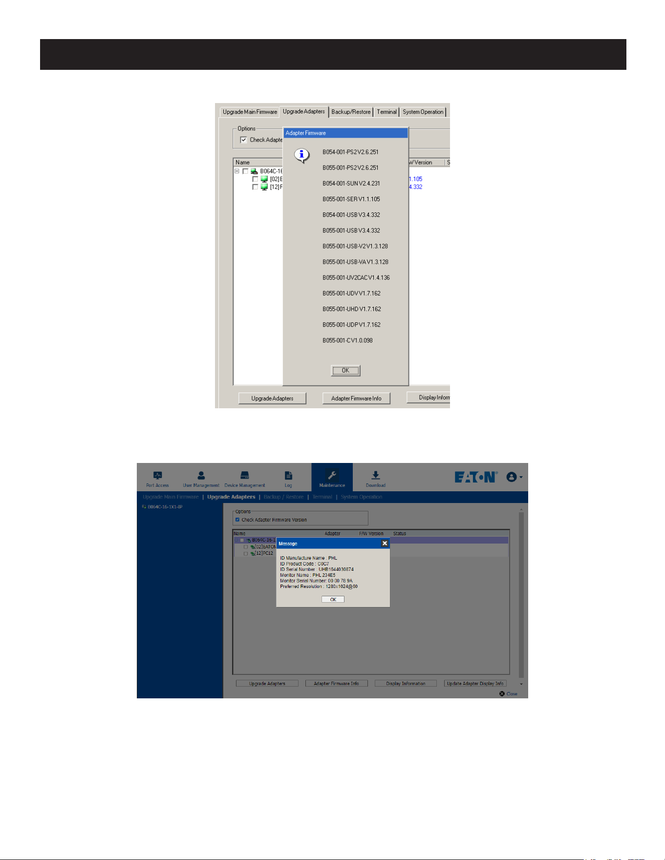
135
7. Administration
AP GUI
Display Information
The Display Information button will query and show the locally connected monitor’s EDID information.
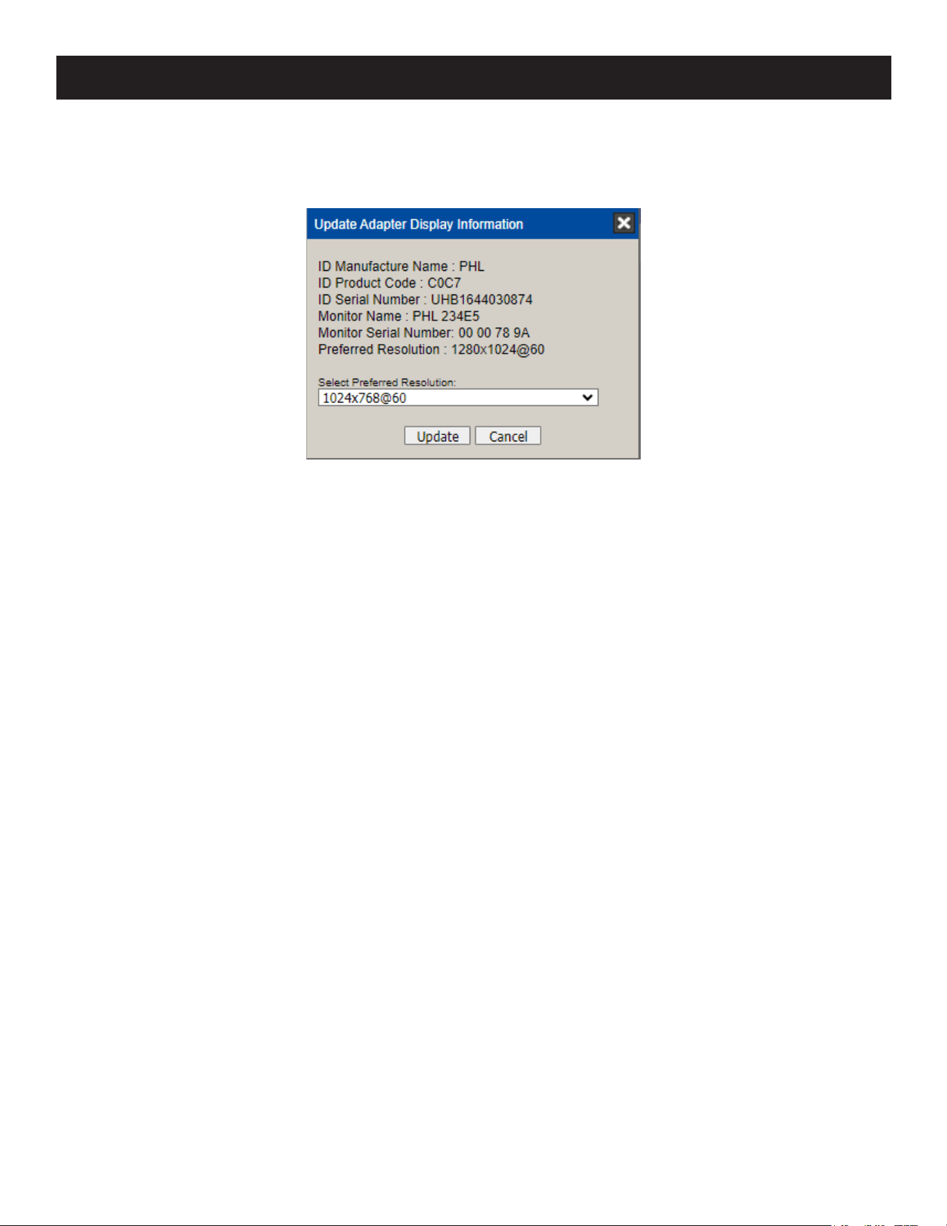
136
7. Administration
Update Adapter Display Info
The Update Adapter Display Info button will query the local monitor’s EDID information and update it on the adapter
cable. The EDID information tells the server’s video card about the hardware of the display it is connected to (in this
case, the monitor connected to the KVM console).
Use the Display Information button to obtain the local monitor’s Preferred Resolution (optional) and apply it with the
Select Preferred Resolution drop down menu, then click Write. If the local console is not connected to a monitor, the
default EDID setting is loaded on the adapter cable.
7.9.4 Adapter Firmware Upgrade Recovery
Should the adapter firmware upgrade procedure fail for one of the KVM adapter cables and the adapter becomes
unusable, the following adapter firmware upgrade recovery procedure will resolve the problem:
1. Unplug the adapter from the server it is connected to.
2. Slide its firmware upgrade recovery switch (located next to the Cat5e connector) to the RECOVER position.
3. Plug the adapter back into the server.
4. Repeat the adapter upgrade procedure.
After the adapter has been successfully upgraded, unplug the adapter from the server it is connected to, slide the
firmware upgrade recovery switch back to the NORMAL position and plug the adapter back in.
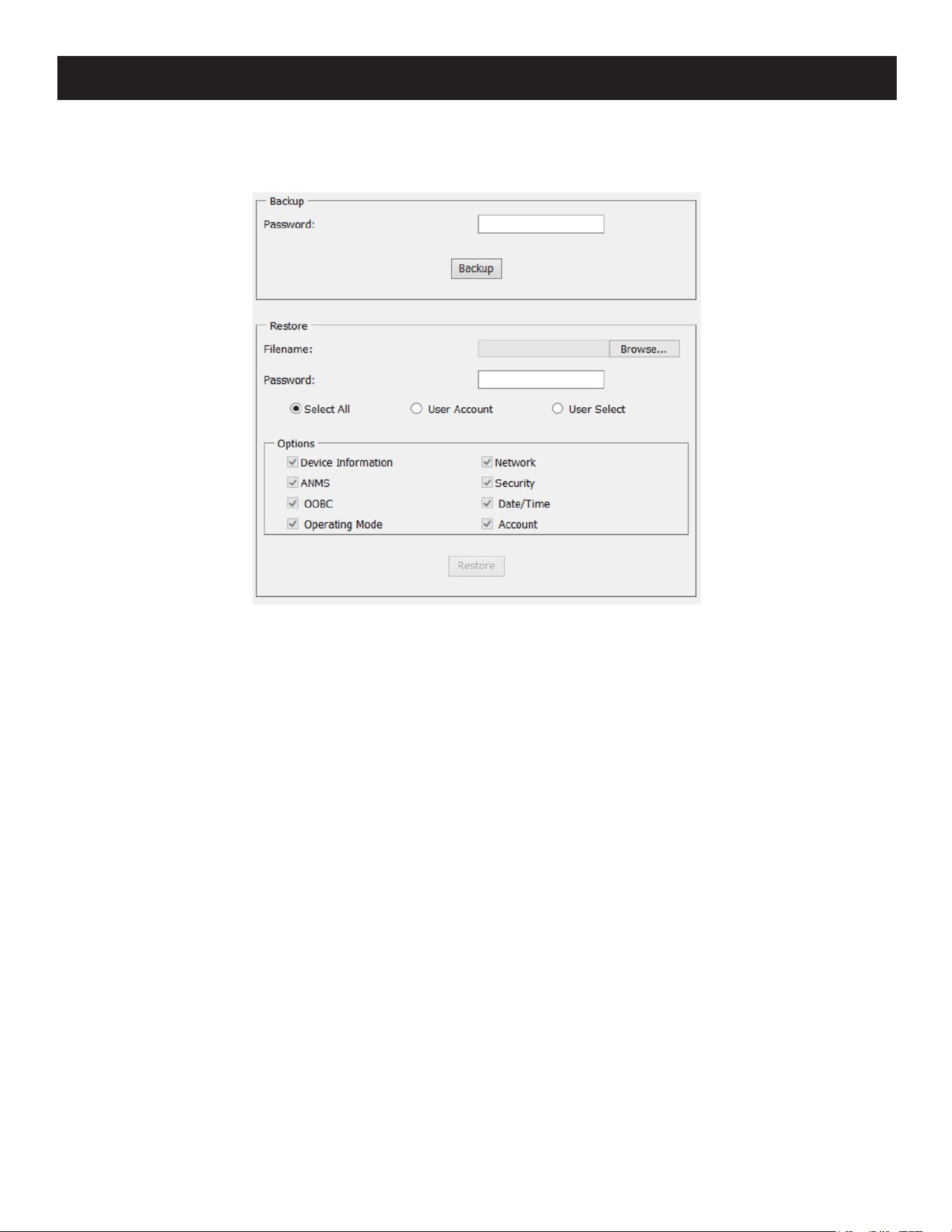
137
7. Administration
7.9.5 Backup/Restore
Selecting the Backup/Restore menu item gives you the ability to back up the switch’s configuration and user profile
information.
Backup
To backup the device’s settings:
1. In the Password field, key in a password for the file.
Notes:
• Setting a password is optional. If you do not set one, the file can be restored without specifying a password.
• If you do set a password, make a note of it, since you will need it to be able to restore the file.
2. Click Backup.
3. When the browser asks what you want to do with the file, select Save to disk, then save it in a convenient location.
Restore
To restore a previous backup:
1. Click Browse, then navigate to the file and select it.
Note: If you renamed the file, you can keep the new name. There is no need to return it to its original name.
2. If you set a password when you created the file, key it in the Password field.
3. Select as many of the options that are presented as you wish to restore.
4. Click Restore.
After the file is restored, a message will appear to inform you that the procedure succeeded.
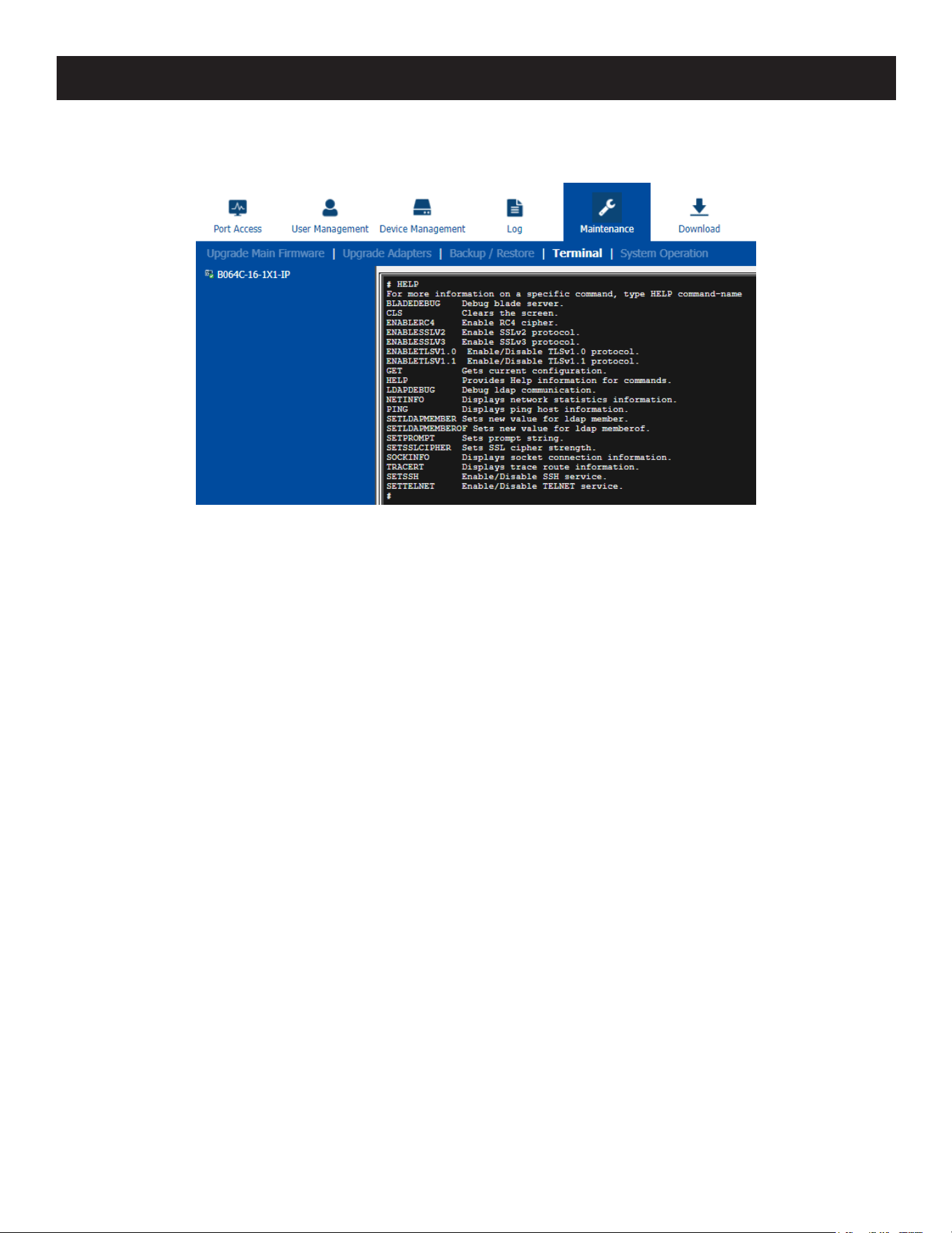
138
7. Administration
7.9.6 Terminal
Terminal is also available for access to more advanced instructions through a terminal-like interface.
Available commands include:
• BLADEDEBUG => Debug blade server.
• CLS => Clears the screen.
• ENABLERC4 => Enable RC4 cipher.
• ENABLESSLV2 => Enables SSLv2 protocol.
• ENABLESSLV3 => Enables SSLv3 protocol.
• ENABLETLSV1.0 => Enables/disables TLSv1.0 protocol.
• ENABLETLSV1.1 => Enables/disables TLSv1.1 protocol.
• GET => Gets current configuration.
• HELP => Provides Help information for commands.
• LDAPDEBUG => Debugs ldap communication.
• NETINFO => Displays network statistics information.
• PING => Displays ping host information.
• SETLDAPMEMBER => Sets new value for ldap member.
• SETLDAPMEMBEROF => Sets new value for ldap memberof.
• SETPROMPT => Sets prompt string.
• SETSSLCIPHER => Sets SSL cipher strength.
• SOCKINFO => Displays socket connection information.
• TRACERT => Displays trace route information.
• SETSSH => Enables/disables SSH service.
• SETTELNET => Enables/disables TELNET service.
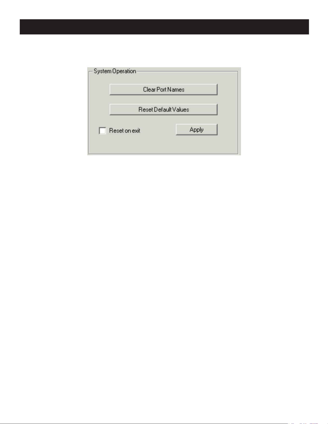
139
7. Administration
7.9.7 Restore Values
The Restore Values page lets you restore certain configuration changes that were made to the KVM over IP switch back
to their original factory default values.
The functions performed on this page are as follows:
Clear Port Names
Clicking this button removes names that have been assigned to the ports.
Restore Default Values
Clicking this button undoes all Customization page changes that have been made to the KVM over IP switch (except for
Port Names), as well as the Network Transfer Rate (on the Network page) and returns the parameters to the original
factory default settings.
Reset on Exit
Place a check here and click Apply to have the KVM over IP switch reset itself and implement all the new settings when
you log out. Following the reset, wait approximately 30 to 60 seconds before logging in again.
If you change the switch’s IP Address, the checkbox is automatically checked and the KVM switch will reset when you log
out. If you clear the check mark before logging out, the changed IP settings will be ignored and the original IP address
settings will remain in effect.
Note: Even though the changed IP settings are ignored, they will remain in the network settings fields. The next time you open this page
the Reset on exit checkbox will automatically be enabled and when the switch resets, the new IP settings thought to be discarded will
instead become those used by the switch. To avoid this problem, go back to the network settings page and make sure the IP settings that
appear in the fields are the ones you want to use.
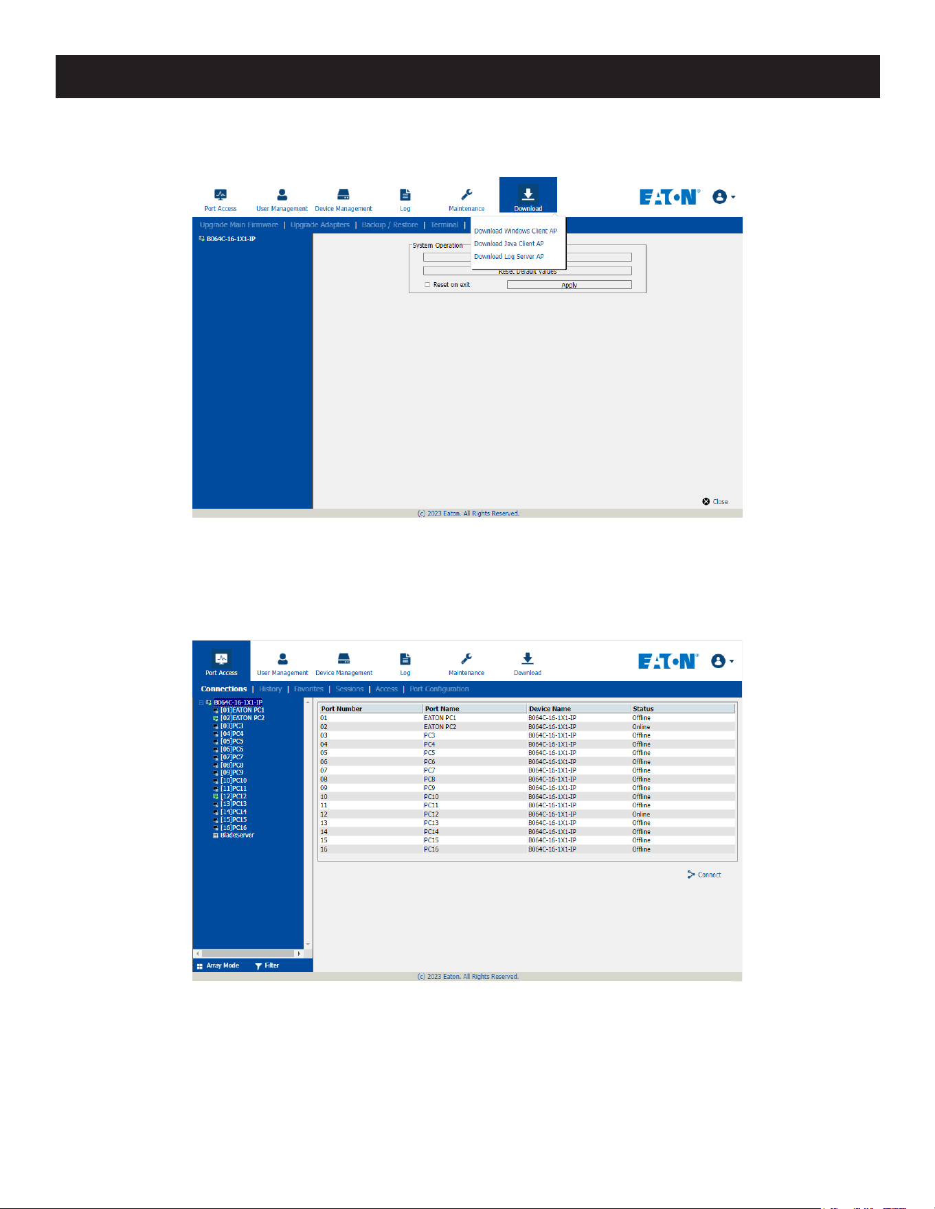
140
7. Administration
7.10 Download
Download is used to download stand-alone AP versions of the Windows Client, Java Client and Log Server
Click the program you want to download, save it to a convenient location on your hard disk and run it.
7.11 Port Operation
Once you have successfully logged in (see 7.8 Logging In), the B064C-16-1X1-IP opens to the Port Access tab’s
Connections page with the first KVM over IP switch selected in the sidebar.
Notes:
• The WinClient and Java Client AP programs have a hidden Control Panel at the upper center of the screen that becomes visible when you
mouse over it. The Browser version’s Control Panel only appears when you switch to a port.
• See 7.5.2 KVM Devices and Ports – Connections Page for details about the Port Access Connections page.
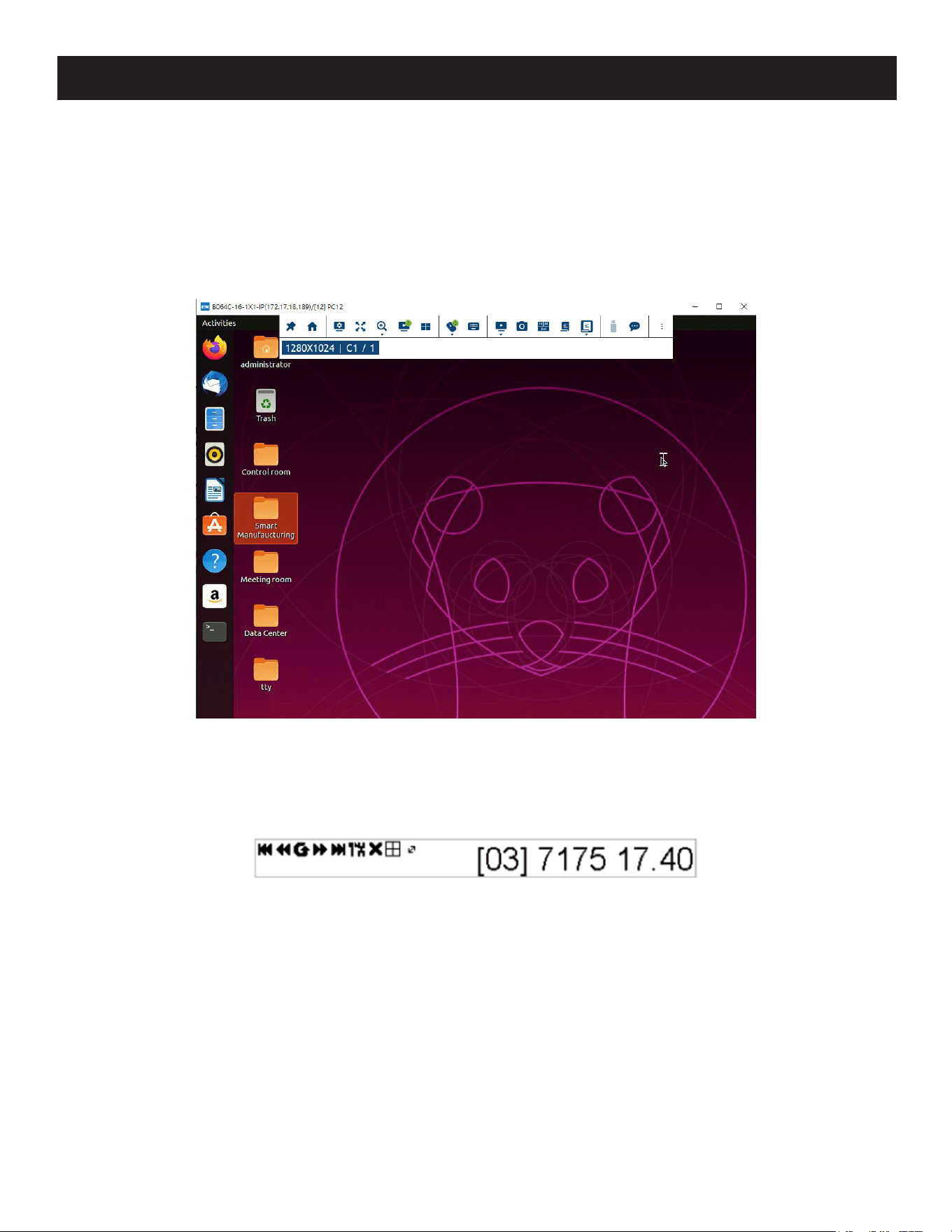
141
7. Administration
7.11.1 Connecting to a Port
All devices, ports and outlets a user is permitted to access are listed in the Sidebar at the left of the page.
• To connect to a port when a device is selected in the Sidebar, double-click its icon in the Sidebar; or double-click
anywhere on its line entry in the main central panel; or select it in the main panel and click Connect at the bottom
right of the page.
• To connect to a port when the port is selected in the Sidebar, click Connect at the right of the Status panel.
Once you switch to a port, its screen will display on your monitor and your keyboard and mouse input will work with the
remote server:
7.11.2 Port Toolbar
The B064C-16-1X1-IP’s interface provides a toolbar to help you with port switching operations from within the captured
port. To open the toolbar, tap the OSD hotkey (Scroll Lock or Ctrl), twice. The toolbar appears at the upper left corner of
the screen:
Depending on the settings that were selected for ID Display, the Port Number and/or the Port Name will display on the
right of the toolbar.
When the toolbar displays mouse and keyboard input has no effect on the server connected to the port. To carry out
operations on the server, close the toolbar by clicking its X icon.
To return to the Port Access Connections page, either click the appropriate icon or tap the OSD hotkey again.
Notes:
• You can adjust the toolbar transparency.
• The toolbar functions and icons are also incorporated in the Control Panel. If you choose to enable them in the control panel, you can
disable the toolbar. To recall the Port Access Connections page when there is no Toolbar, simply tap the OSD hotkey twice.

142
7. Administration
Toolbar Icons
The toolbar icons are explained in the table below.
Icon Purpose
Click to skip to the rst accessible port on the entire installation without having to
recall the Port Access page.
Click to skip to the rst accessible port previous to the current one without having to
recall the Port Access page.
Click to begin Auto Scan Mode. The KVM over IP switch automatically switches among
the ports that were selected for Auto Scanning with the Filter function. This allows you
to monitor their activity without having to switch among them manually.
Click to skip from the current port to the next accessible one without having to recall
the Port Access page.
Click to skip from the current port to the last accessible port on the entire installation
without having to recall the Port Access page.
Click to recall the Port Access page.
Click to close the toolbar.
Click to invoke Panel Array Mode (see 7.11.3 Panel Array Mode).
Lets you specify how long the Cat5e/6 cable between the port and the KVM adapter
cable is. Click the icon to select one of three cable length settings:
Short: up to 82 ft. (25 m)
Medium: between 65 and 115 ft. (20 and 35 m)
Long: above 115 ft. (35 m)
Toolbar Hotkey Port Switching
When the toolbar displays, you can use hotkeys to provide KVM focus to a port directly from the keyboard. The B064C-
16-1X1-IP provides the following hotkey features:
• Going directly to a port by keying in its port number and clicking Enter.
• Auto Scanning
• Skip Mode Switching
The hotkeys are: A and P for Auto Scanning and the Arrow Keys for Skip Mode.
Notes:
• For hotkey operations to take place, the toolbar must be visible (see 7.11.2 Port Toolbar).
• To use the keys designated as hotkeys (i.e. A, P, etc.) for normal, non-hotkey purposes, you must first close the toolbar.
• For issues affecting multiple user operation in Auto Scan Mode, see 7.11.4 Multiuser Operation.

143
7. Administration
Auto Scanning
The Scan function automatically switches among all the ports that are accessible to the currently logged on user at
regular intervals so the user can monitor their activity automatically. Users can also limit the number of ports scanned
with the Sidebar’s Filter function.
• Setting the Scan Interval
The amount of time Auto Scan dwells on each port is set with the Scan Duration setting.
• Invoking Auto Scan
To start Auto Scanning with the toolbar showing tap the A key. The Auto Scan function cycles through the ports in
order starting from the first port on the installation. An
S
appears in front of the Port ID Display to indicate the port
is being accessed in Auto Scan Mode.
• Pausing Auto Scan
While you are in Auto Scan Mode, you can pause scanning to better maintain focus on a particular server by pressing
P. During the time that Auto Scanning is paused, the S in front of the Port ID will blink.
Pausing when you want to maintain focus on a particular server can be more convenient than exiting Auto Scan Mode
because when you Resume scanning, you start from where you left off. If on the other hand, you were to exit and
then restart Auto Scan Mode, the scanning would start over from the very first server on the installation.
To Resume Auto Scanning after a pause, press any key except [Esc] or the [Spacebar]. Scanning continues from
where it left off.
• Exiting Auto Scan
While Auto Scan Mode is in effect, ordinary keyboard functions are suspended. You must exit Auto Scan Mode to
regain normal control of the keyboard. To exit Auto Scan Mode, press [Esc] or [Spacebar]. Auto Scanning stops
when you exit Auto Scan Mode.
Skip Mode
Skip Mode allows you to switch ports to monitor the servers manually. You can focus on a particular port for as long or
as little as you like (as opposed to Auto Scanning, which automatically switches after a fixed interval). The Skip Mode
hotkeys are the four Arrow keys.
Arrow Action
f
Skips from the current port to the rst accessible port previous to it.
g
Skips from the current port to the rst accessible port that comes after it.
h
Skips from the current port to the rst accessible port on the installation.
i
Skips from the current port to the last accessible port on the installation.
Recalling the Port Access Page
To dismiss the toolbar and return to the Port Access page, do one of the following:
• Tap the OSD Hotkey once.
• From the toolbar, click the icon that recalls the Port Access page.
The toolbar will close and the Port Access Page will appear.
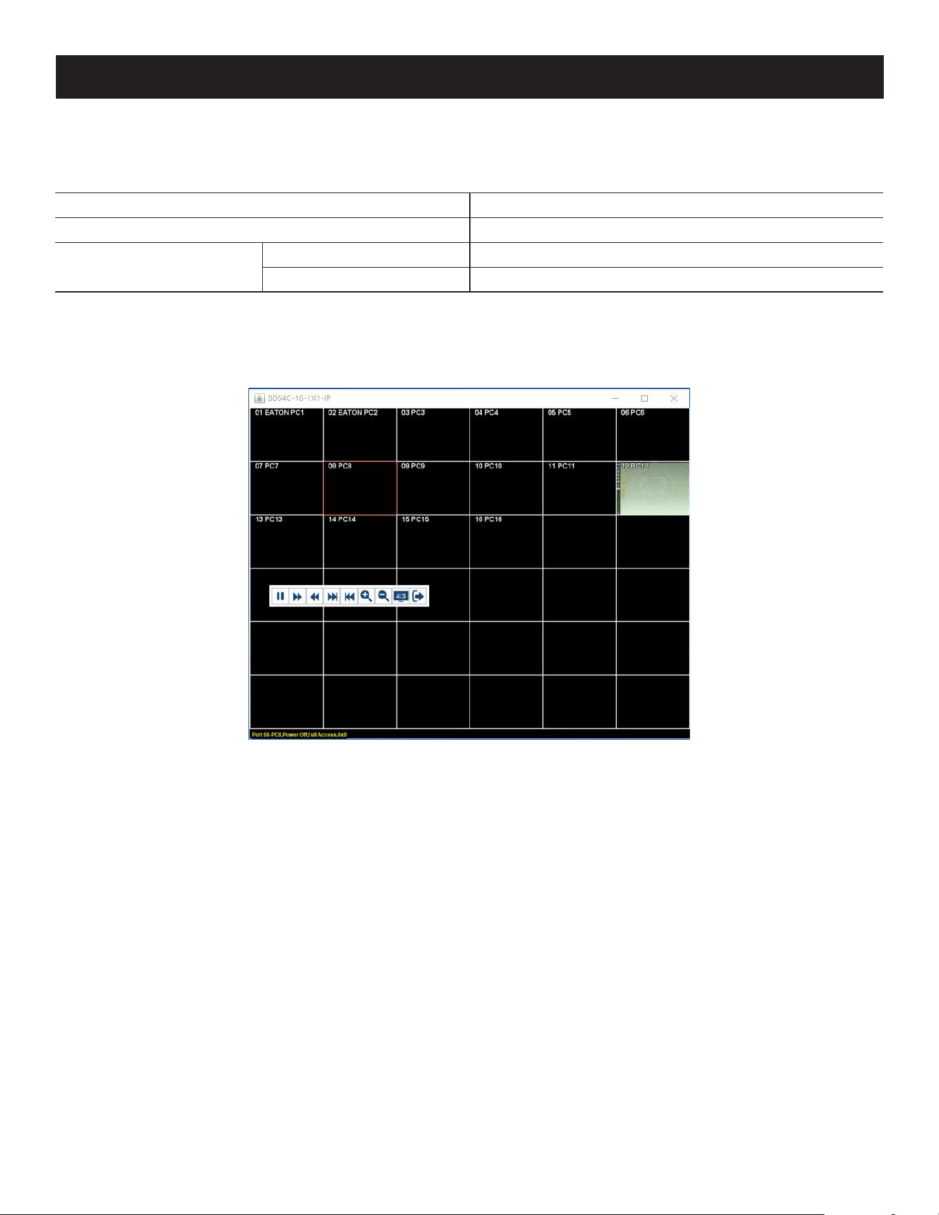
144
7. Administration
OSD Hotkey Summary Table
The following table presents a summary of the OSDHotkey actions after you have accessed a port. See 7.7.5 User
Preferences to set the OSD Hotkey.
To... Do This...
Open the Toolbar Click the OSD Hotkey twice
Open the Port Access Page
The Toolbar is open Click the OSD Hotkey once
The Toolbar is not open Click the OSD Hotkey three times
7.11.3 Panel Array Mode
Clicking the toolbar’s Panel icon invokes Panel Array Mode. Under this mode, the screen divides into a grid of up to 64
panels:
• Each panel represents one of the switch’s ports beginning with Port 1 at the upper left, and going from left to right,
top to bottom.
• The number of panels in the array can be selected by clicking the Show More Ports and Show Fewer Ports
symbols on the panel array toolbar.
• Only ports that are accessible to the user are displayed. For ports that are not accessible, the panel will be blank.
• If the server connected to a port is online, its screen displays in its panel; otherwise the panel will be blank.
• Hovering a mouse over a panel displays information about the port (port name, online status, port access status and
resolution).
• You can access a server connected to a port by moving the mouse pointer over its panel and clicking. You can switch
to the server exactly as if you had selected it from the Port Access page.

145
7. Administration
Panel Array Toolbar
The panel array toolbar provides shortcut navigation and control of the panel array. The toolbar can be dragged
anywhere on the screen. Mousing over an icon opens a “tooltip” that provides a short description of the icon’s function.
Click and drag to move the toolbar.
Note: This icon is only available with the Windows Clients. To move the Java Client toolbars, click on
any empty space and drag.
Pause panel scanning, leaving the focus on the panel that currently has it.
Move back four panels.
Move to the previous panel.
Move to the next panel.
Move ahead four panels.
Show More Ports: Increase the number of panels in the array.
Show Fewer Ports: Decrease the number of panels in the array.
Toggle 4/3 aspect ratio.
Exit Panel Array mode.
Note: When Panel Array Mode is being used by one of the members of the bus, independent bus switching does not work. For rules of
multiple user operation and bus usage in Panel Array Mode, see 7.11.4 Multiuser Operation.
7.11.4 Multiuser Operation
The B064C-16-1X1-IP supports multiuser operation. When multiple users simultaneously access the switch from client
computers, the rules of precedence that apply are shown in the following table:
Operation Rule
General Each bus is independent. Each user can open his own independent GUI Main Page.
Auto Scan Mode
If a user has invoked Auto Scan Mode and another user logs on, at rst the new
user will see the GUI Main Page. However, as soon as they access any port, they will
automatically enter Auto Scan Mode.
Any user can halt Auto Scan Mode by recalling the GUI Main Page. When this occurs,
Auto Scan Mode stops and all the other users on the bus are switched to the port that
was being accessed when Auto Scan Mode stopped.
Panel Array Mode
• If a user has invoked Panel Array Mode and another user logs on, the new user
will see the GUI Main Page. However as soon as they access any port, they will
automatically enter Panel Array Mode.
• Panel Array Mode continues until the original user stops it (Administrators can
override Panel Array Mode, however).
• Only the user who starts Panel Array Mode can use the Skip Mode function.
• Only the user who starts Panel Array Mode can switch ports. Other users
automatically switch to the ports that the original user selects. However, if one of the
other users does not have access rights to the port that the original user switches
to, that user will not be able to view the port.
• Individual users can increase or decrease the number of panels they wish to view
in Panel Array Mode. However, the picture quality may decrease as the number of
panels increases.
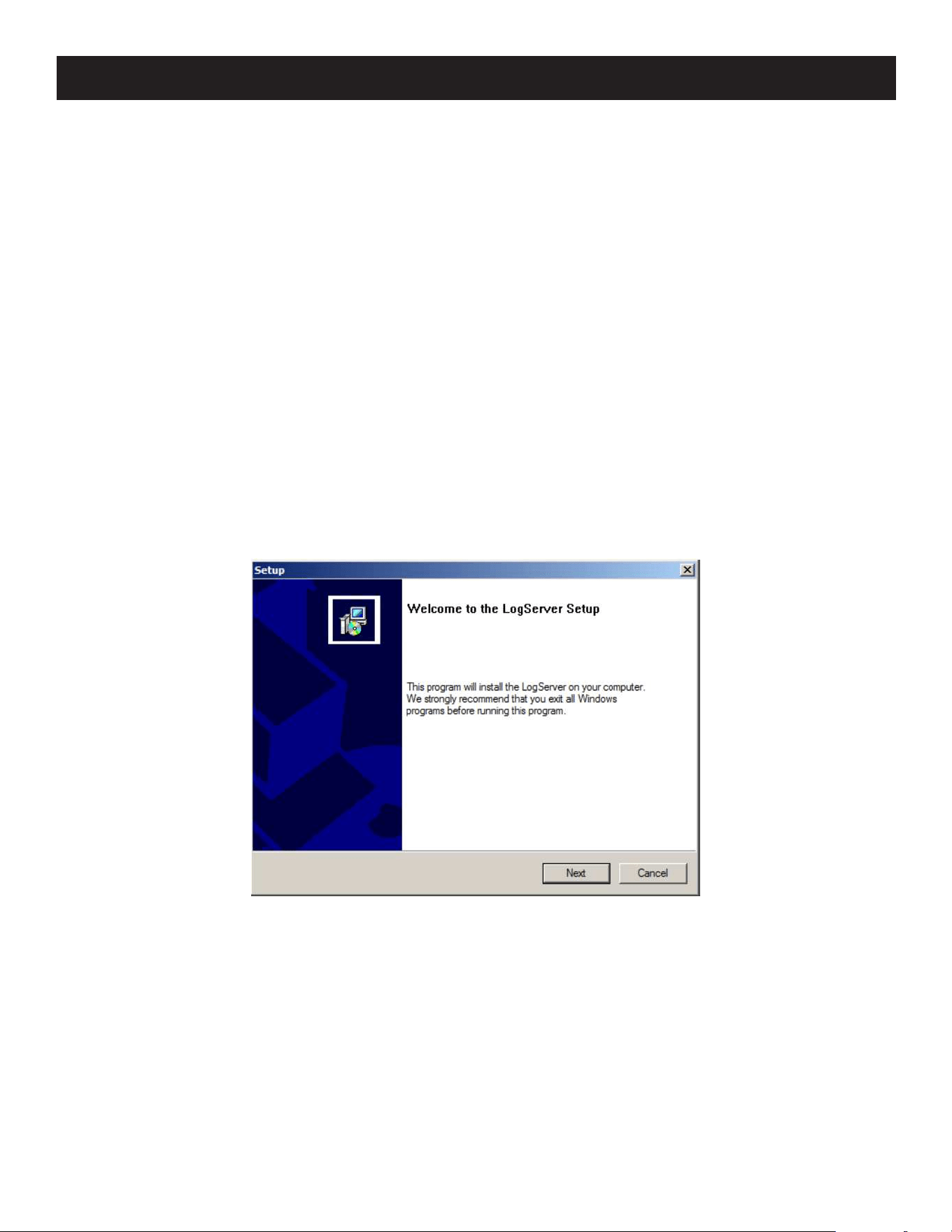
146
Users and Buses
• All KVM over IP switches support independent bus switching. With independent bus switching, if a user switches to a
port that is being utilized by someone on a different bus, only the user that switched ports goes to the new port and
the new bus (the other users on the original bus remain on the original port and original bus).
• Independent bus switching does not work when Auto Scan Mode or Panel Array Mode is being used by one of the
members of the bus.
• We recommend that the user who starts Panel Array Mode set it to display at least four panels. Otherwise, it is
possible other users may only receive part of the picture.
7.12 Log Server
The Windows-based Log Server is an administrative utility that records all events that take place on selected B064C-16-
1X1-IP units and writes them to a searchable database.
7.12.1 Log Server Installation
1. Log into the B064C-16-1X1-IP.
2. Click the Download tab and download the Log Server AP program.
3. Go to the location on your hard disk that you downloaded the Log Server program to and double click its icon
(LogSetup.exe) to access the Windows Client Connection Screen.
Note: If the browser cannot run the file, save it to disk and run the file from your disk.
The Log Server installation screen will appear:
4. Click Next, then follow the on-screen instructions to complete the installation and have the Log Server program icon
placed on your desktop.
7. Administration
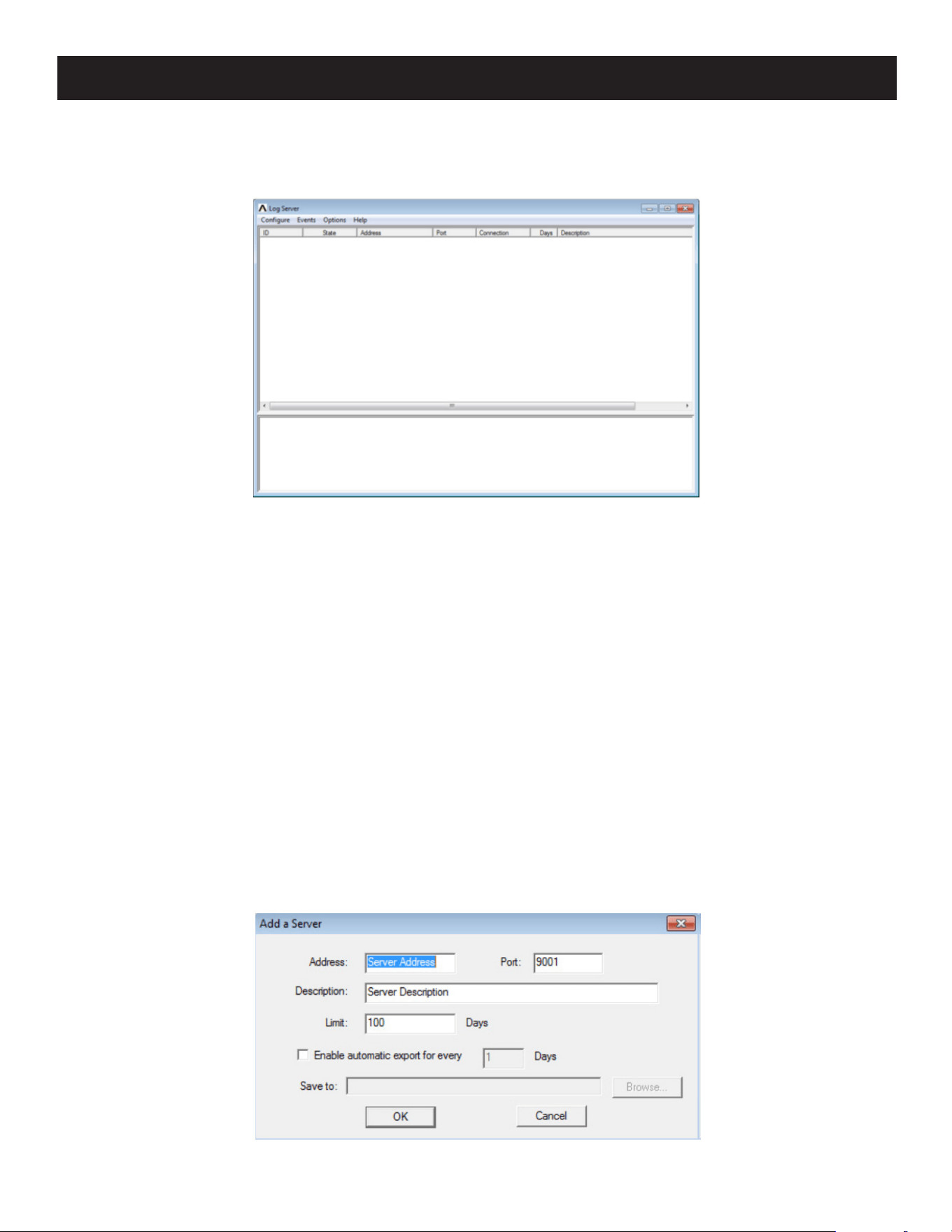
147
7. Administration
7.12.2 Log Server Startup
To start the Log Server, double click the program icon or key in the full path to the program on the command line. The
first time you run it, a screen similar to the one below will appear:
Notes:
• The MAC address of the Log Server computer must be specified in the ANMS settings.
• The Log Server requires the Microsoft Jet OLEDB 4.0 driver.
The Menu Bar
The Menu bar consists of four items:
• Configure
• Events
• Options
• Help
Note: If the Menu Bar appears to be disabled, click in the List window to enable it.
Configure
The Configure menu contains three items: Add, Edit and Delete. They are used to add new units to the List, edit the
information for units already on the list or delete units from the list.
• To add a unit to the list, click Add.
• To edit or delete a listed unit, first select the target in the List window, then open this menu and click Edit or Delete.
When you choose Add or Edit, a dialog box similar to the one below will appear:
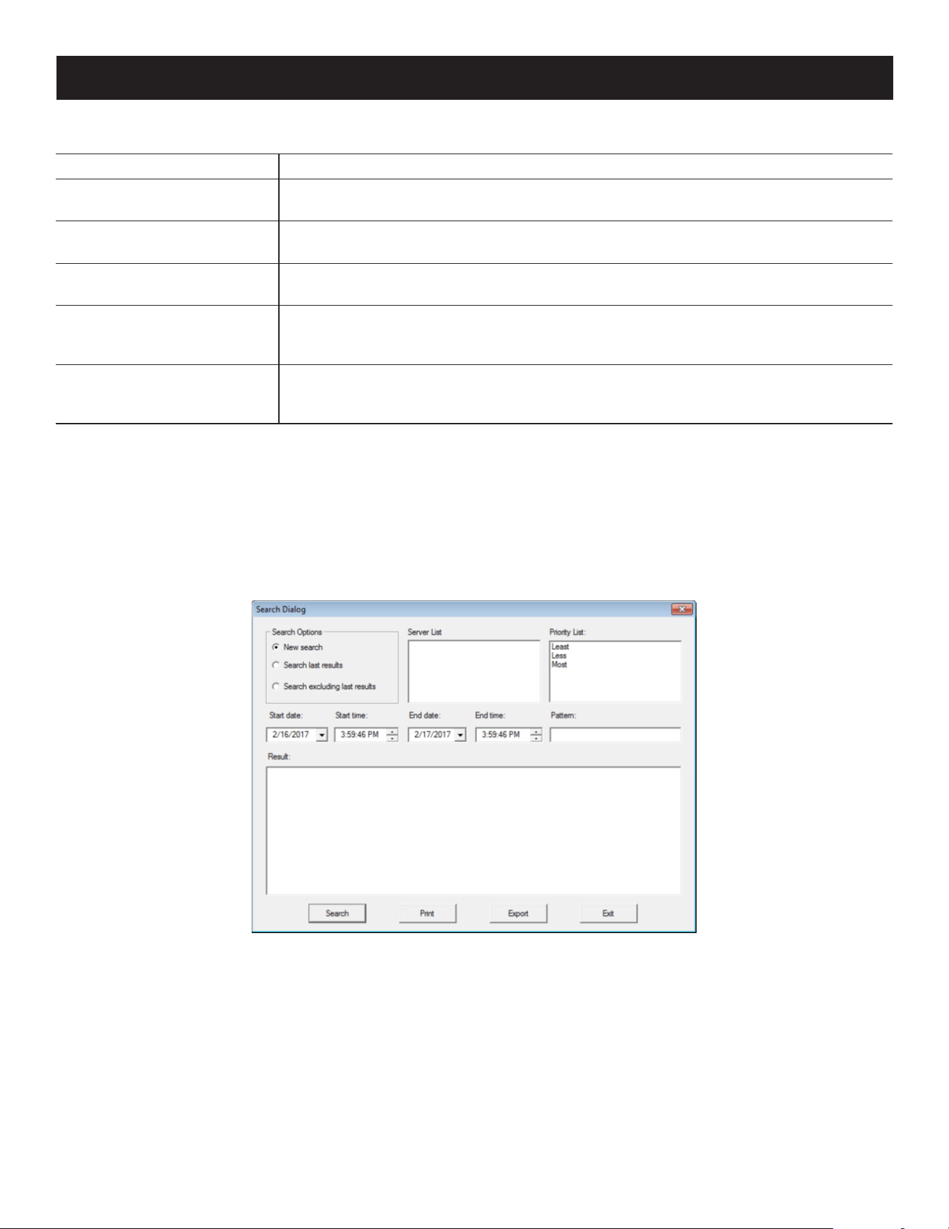
148
7. Administration
A description of the fields is provided in the table below:
Field Explanation
Address
This can either be the IP address of the computer the Log Server is running on, or its
DNS name.
Port
The port number that was assigned to the Log Server under Device Management (see
7.8 Log Server).
Description
This eld is provided so that you can put in a descriptive reference for the unit to help
identify it.
Limit
This species the number of days an event should be kept in the Log Server's
database. Events that exceed the amount of time specied here can be removed with
the Maintenance function (see 7.9 Maintenance).
Enable Automatic Export
Check this box and enter the number of days to pass before the log server
automatically exports a log le. Click Browser to select the directory where you want
the log le saved to.
Fill in or modify the fields, then click OK to finish.
Events
The Events Menu has two items: Search and Maintenance.
Search
Search allows you to search for events containing specific words or strings. When you access this function, a screen
similar to the one below will appear:

149
7. Administration
A description of the items is provided in the table below:
Item Description
New Search
This is one of three radio buttons that dene the scope of the search. If it is selected,
the search is performed on all the events in the database for the selected unit.
Search Last Results
This is a secondary search performed on the events that resulted from the previous
search.
Search Excluding Last Results
This is a secondary search performed on all the events in the database for the
selected unit excluding the events that resulted from the previous search.
Server List
Matrix KVMs are listed according to their IP address. Select the unit that you want to
perform the search on from this list. You can select more than one unit for the search.
If no units are selected, the search is performed on all.
Priority
Sets the level for how detailed the search results display should be. Least is the most
general and Most is the most specic. Least results appear in black and Less results
appear in blue; most results appear in red.
Start Date
Select the date that you want the search to start from. The format follows the YYYY/
MM/DD convention, as follows:
2024/11/04
Start Time
Select the time that you want the search to start from. The format follows the
HH:MM:SS convention.
End Date Select the date that you want the search to end at.
End Time Select the time that you want the search to end at.
Pattern
Key in the pattern that you are searching for here. The multiple character wildcard (%)
is supported. (e.g., h%ds would match hands and hoods).
Results Lists the events that contained matches for the search.
Search Click this button to start the search.
Print Click this button to print the search results.
Export Click this button to save the search results to le.
Exit Click this button to exit the Log Server.
Maintenance
This function allows the administrator to perform manual maintenance of the database, such as erasing specified
records before their expiration time is up.
Options
Network Retry allows you to set the number of seconds that the Log Server should wait before attempting to connect if
its previous attempt to connect failed. When you click this item, a dialog box similar to the one below will appear:
Key in the number of seconds, then click OK to finish.
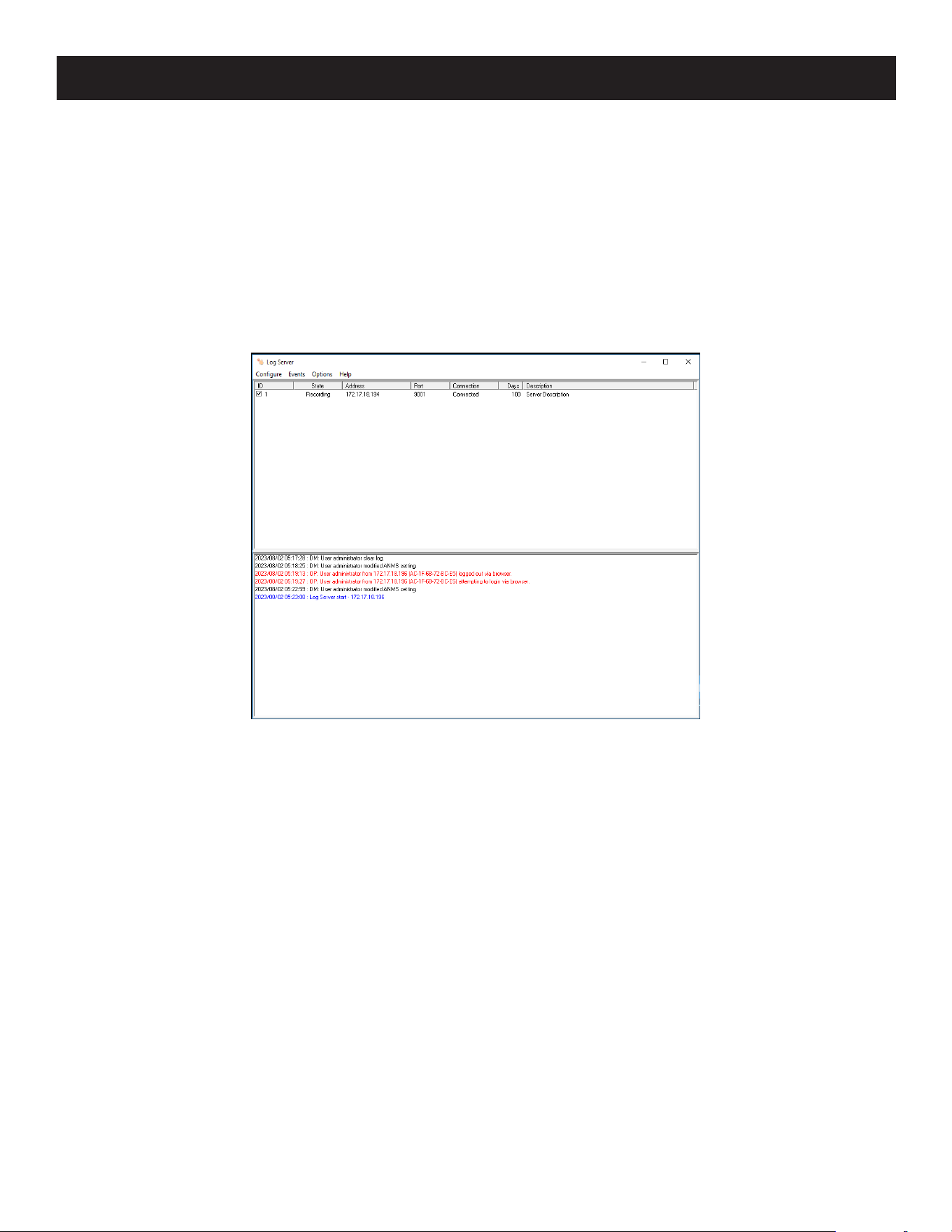
150
7. Administration
Help
From the Help menu, click Contents to access the online Windows Help file. The help file contains instructions on how
to set up, operate and troubleshoot the Log Server.
7.12.3 Log Server Main Screen
The Log Server Main Screen is divided into two main panels.
• The upper (List) panel lists all units that have been selected for the Log Server to track.
• The lower (Event) panel displays the tick information for the currently selected unit (if there is more than one unit, the
selected unit is the one that is highlighted).
• To select a unit in the list, simply click on it.

151
7. Administration
The List Panel
The List panel contains six fields:
Field Explanation
ID
Provides the list of devices which have been added to the log server. Use the checkbox
to select devices for which you want to view logs.
State
Displays whether or not the Log Server records the ticks for this unit. If the ID
checkbox is checked, the eld displays Recording and the ticks are recorded. If the ID
checkbox is not checked, the eld displays Paused, and the ticks are not recorded.
Note: Even though a unit is not currently the one selected, if its ID checkbox is checked,
the Log Server will still record its ticks.
Address
This is the IP Address or DNS name that was given to the unit when it was added to
the Log Server.
Port This is the Access Port number assigned to the unit.
Connection
• If the Log Server is connected to the unit, this eld will display as Connected.
• If the Log Server is not connected, this eld will display as Waiting. This means that
the Log Server’s MAC address has not been set properly and needs to be set on the
Device Management Date/Time page.
Days
This eld displays the number of days that the unit's log events are to be kept in the
Log Server's database before expiration.
Description
This eld displays the descriptive information given for the unit when it was added to
the Log Server.
Event Panel
The lower panel displays log events for the currently selected unit. Note that if there is more than one unit, even
though they are not currently selected if their Recording checkbox is checked, the Log Server will record their log events
and keep them in its database.

152
8. Troubleshooting
8.1 Administration
Problem Resolution
After upgrading rmware, the
B064C-16-1X1-IP still appears to be using the
old rmware version.
Your Internet browser is displaying cached web pages, not new ones.
Clear your browser cache, delete all temporary Internet les and
cookies, close the Internet browser, and then open a new instance of
the browser.
The default network setting for the
B064C-16-1X1-IP is DHCP, but the network
uses xed IP addresses and does not have a
DHCP server.
Use the local console OSD’s F4 function to give the B064C-16-1X1-IP a
xed IP address.
8.2 Operation
8.2.1 General Operation
Problem Resolution
Erratic Operation Press and hold the Reset Switch for longer than three seconds.
Mouse and/or keyboard not responding due
to improper mouse and/or keyboard reset.
Unplug the cable(s) from the console port(s), then plug it back in
again.
Sudden loss of network connection due to
local reset of B064C-16-1X1-IP.
Close your B064C-16-1X1-IP connection. Wait approximately 30
seconds and log in again.
Mouse Pointer Confusion
If you nd the display of two mouse pointers (local and remote) to be
confusing or annoying, you can use the Toggle Mouse Display function
to shrink the non-functioning pointer.
Some characters that are keyed in do not
display on the remote system
This is likely due to the local OS keyboard language and the remote
OS keyboard language being dierent. Make sure that the keyboard
language for both systems are the same.
Keyboard and/or mouse do not work after
computer boots up.
For computers with PS/2 connectors, if you are using 2L-520xP cables,
make sure all connectors (keyboard, video, and mouse) are plugged
into their ports on the computer before starting the computer.
Plugging the cables in after the computer has booted will not resolve
the problem.
When I emulate the Sun keyboard, I cannot go
into OK Mode ([Stop] [A]).
To go into OK Mode, use the following key sequence:
1. Press and release [Ctrl].
2. Press and hold [T].
3. Press and hold [A].
4. Release [T] and [A] together.
There are ghost images on the external
monitor.
The distance between the external console and the B064C-16-1X1-IP
is too great. The maximum VGA cable distance should not exceed
65 ft. (20 m) and in some cases, may need to be shorter. Replace the
VGA cable with one of an appropriately short length.
I cannot set the computers’ screen resolutions
higher than 1280 x 1024, even though the
B064C-16-1X1-IP supports 1920 x 1200 for
remote computers.
The maximum screen resolution of the B064C-16-1X1-IP’s integrated
LCD monitor is 1280 x 1024. To protect it from being damaged by
resolutions that are beyond its display capability, we recommend the
screen resolutions of the connected computers be set to 1280 x 1024
or lower.
If you wish to set the screen resolutions of the connected computers
to something higher than 1280 x 1024, see 8.2.11 Screen
Resolutions Higher than 1280 x 1024.

153
8. Troubleshooting
Problem Resolution
When I switch to one of the computers on
my installation, the LCD monitor screen goes
blank. All I see is a black screen.
The maximum screen resolution of the B064C-16-1X1-IP’s integrated
LCD monitor is 1280 x 1024. The screen resolution of the problem
computer is set to something that is too high for the B064C-16-1X1-
IP’s LCD monitor to display.
To resolve the problem, connect an external KVM console (with
a monitor capable of displaying the problem computer’s screen
resolution) to the B064C-16-1X1-IP’s external console ports. Use the
external console to access the problem computer and reduce its
resolution to 1280 x 1024.
Note: Although the LCD monitor only supports video resolutions of up to 1280
x 1024, the B064C-16-1X1-IP, itself can support video resolutions up to 1920
x 1200 @ 60 Hz. If you wish to set the screen resolutions of the connected
computers to something higher than 1280 x 1024, see 8.8 Screen Resolutions
Higher than 1280 x 1024 for details.
My B064C-16-1X1-IP unit is not listed in the
Device List of the IP Installer.
• Make sure the Broadcast function is enabled from your switch or
router for the auto-discover to work properly.
• Make sure to turn o your rewall and/or antivirus software
temporarily for the auto-discover to work properly.
• Make sure the unit and the PC are under the same network
segment.
I have been provided an account, but I am
unable to log in.
1. Make sure you have correctly specied your Username and
Password.
2. Make sure the administrator has given you the necessary
permission to access the switch.
I cannot access the switch, even though I have
specied the IP address and port number
correctly.
If the switch is behind a router, the router’s Port Forwarding (also
referred to as Virtual Server) feature must be congured (see 8.3 Port
Forwarding).
When logging in from a browser, the following
message appears: 404 Object Not Found.
If a login string has been set, make sure to include the forward slash
and correct login string when you specify the KVM over IP switch IP
address (see 7.8 Login String).
Sudden loss of network connection.
Close your connection to the KVM over IP switch. Wait approximately
30 seconds and log in again.
There is no remote server video display on the
client computer.
Check that your KVM Adapter Cable’s rmware version is the same as
the version stored in the switch’s Main rmware (see 7.9.3 Upgrade
Adapters).
Set the remote server resolution to 1280 x 1024 or less.
There is no remote server video display on
the client computer, but mouse movements
appear on the local console and mouse clicks
have no eect.
Press and release the left Alt key, then press and release the right Alt
key
The display on the client computer is distorted
and performing an Auto sync does not resolve
the problem.
Switch ports to a port with a dierent resolution, then switch back.
If the above did not resolve the problem, change the resolution and
refresh rate for the system running on the port. Afterward, you can
run at the new resolution or switch back to the original resolution.
The Lock Key LEDs on the Control Panel do
not accurately reect the actual locked status
of my keyboard input.
When you rst connect, the display may not accurately reect the
LEDs on your keyboard. To resolve the problem, click the LEDs on
the Control Panel until they match your keyboard. Afterward, when
you change them from the keyboard, they will change on the Control
Panel.
When I log in, the browser generates a CA Root
certicate is not trusted or a Certicate Error
response.
The certicate’s name is not found on Microsoft’s list of Trusted
Authorities. The certicate can be trusted (see 7.1.2 Trusted
Certicates).

154
8. Troubleshooting
Problem Resolution
In multiuser operation, I had exclusive (or
occupy) rights on the port I was viewing. After
I recalled the Port Access page and then
returned to the port I was occupying, it had
been taken over by another user. Why did this
happen?
If you try to return to the port by selecting again in the tree, the switch
acts as if you are accessing the port for the rst time. If another user
was waiting on the port, they take precedence and get the port. The
correct way to return to the port is to click the Close icon at the top
right of the Port Access page.
8.2.2 Mouse Problems
Problem Resolution
Mouse and/or keyboard are not responding.
• Check that your KVM adapter cable’s rmware version is the same
as the version stored in the switch’s Main rmware (see 7.9.3
Upgrade Adapters).
• Unplug the cable(s) from the console port(s), then plug it/them back
in.
Mouse movement extremely slow.
There is too much data being transferred for your connection’s
bandwidth. Lower the video quality so less video data is transmitted.
There are two mouse pointers after the
remote server is accessed.
Select another pointer type.
When the mouse pointer is in Single Pointer
mode, I cannot access the Control Panel.
Recall the Control Panel and immediately change the pointer to Dual
mode.
Why is there a Dual Pointer mode?
When you are not in Mouse DynaSync Mode, you need the two
pointers so that you know the remote server pointer is actually at the
location you think it is.
Otherwise, you may perform a mouse operation and due to net lag,
the remote server pointer may not be at the location your client
computer pointer is.
Mouse pointer confusion.
If you nd the display of two mouse pointers (local and remote) to
be confusing or annoying, use the Toggle Mouse Display function to
shrink the non-functioning pointer.
When I log in with my Windows system, the
local and remote mouse pointers do not sync.
1. Check the status of the Mouse Sync Mode setting. If it is set
to Automatic, change the setting to Manual and refer to the
information for Manual Mouse Synchronization.
2. If you are in Manual mode, use the AutoSync feature to sync the
local and remote monitors.
3. If that does not resolve the problem, use the Adjust Mouse feature
to bring the pointers back in sync.
4. If the above fails to resolve the problem, refer to 8.6.1 Additional
Mouse Synchronization Procedures for further actions.
When I log in with my Mac system, the local
and remote mouse pointers do not sync.
There are two automatic Mouse DynaSync settings: the default, and
Mac2. If mouse synchronization is not satisfactory with the default, try
the Mac 2 setting.
When I log in with my Sun system, the local
and remote mouse pointers do not sync
1. Automatic Mouse DynaSync sync only supports USB mice on
Windows and Mac (G4 or higher) systems. You must sync the
pointers manually.
2. If the above fails to resolve the problem, refer to 8.6.1 Additional
Mouse Synchronization Procedures for further actions..

155
8. Troubleshooting
Problem Resolution
When I log in with my Linux system, the local
and remote mouse pointers do not sync.
1. Automatic Mouse DynaSync sync only supports USB mice on
Windows and Mac (G4 or higher) systems. You must sync the
pointers manually.
2. If the above fails to resolve the problem, refer to 8.6.1 Additional
Mouse Synchronization Procedures for further actions.
8.2.3 Virtual Media
Problem Resolution
Virtual Media does not work.
The remote server’s mainboard does not support USB. If there is a
newer rmware and BIOS version for the remote server’s mainboard
(e.g., one that supports USB) get it from the manufacturer and
upgrade the server’s mainboard rmware and BIOS.
There is no Virtual Media icon on my Control
Panel.
1. Virtual Media only supports devices connected with
KB055-001-UDV, B055-001-UHD, B055-001-UDP,
B055-001-USB-V2, B055-001-USB-VA, or B055-001-UV2CAC KVM
SIUs with B064C-16-1X1-IP switches.
2. You must be have Administrator privileges on your client computer
(this is a Windows limitation).
I cannot boot my remote server from my
Virtual Media drive.
Your remote server’s BIOS does not support booting from a USB
drive. Get the latest rmware and BIOS version for your mainboard
from the manufacturer and upgrade your mainboard BIOS.
If I connect a USB oppy drive to a remote
server, it can boot the remote server.
However, if I map it to the remote server as a
Virtual Media drive, it cannot boot the remote
server.
USB oppy drives have two format types: UFI and CBI. Both can be
used for OS level virtual media functions, but currently only UFI is
supported for BIOS level (such as boot) functions.
I cannot mount a Folder as a Virtual Media
device.
If the actual Folder is formatted with the FAT16 le system, it cannot
be mounted if its size exceeds 2GB.

156
8. Troubleshooting
8.2.4 Windows Client
Problem Resolution
A "Login Failed" error appears and Windows
Client Viewer cannot be run.
1. Make sure your KVM over IP Switch is updated to the latest
rmware version.
2. Make sure the required service ports, such as 80, 443, and 9000,
are allowed by your Firewall.
3. Close the viewer and try again.
Remote mouse pointer is out of sync.
1. Use the AutoSync feature to sync the local and remote monitors.
2. If that does not resolve the problem, use the Adjust Mouse feature
to bring them back in sync.
3. If the two methods described above fail to resolve the problem,
use the Toggle Mouse Display function.
Part of remote window is o my monitor.
1. Perform an Auto Sync.
2. If Keep Screen Size is not enabled, use the AutoSync feature to
sync the local and remote monitors.
3. If Keep Screen Size is enabled, you can scroll to the areas that are
o screen.
My antivirus program reports that there is
a trojan after I access the B064C-16-1X1-IP
with my browser and then open the Windows
Client Viewer.
The Windows Client Viewer uses an ActiveX plug-in (windows.ocx) that
some antivirus programs mistakenly see as a virus or trojan. We have
tested our rmware extensively and found no evidence of a virus or
trojan. You can add the plug-in to your antivirus program’s White List
and use the Viewer safely. If you are reluctant to use the Windows
Client Viewer, however, you can simply use the Java Client Viewer,
instead.
After upgrading the rmware, the WinClient
ActiveX Viewer or WinClient AP does not run.
The old version of your .ocx le was not deleted. You must delete the
old le. There are two methods to delete the le.
1. For the ActiveX Viewer: Open IE Tools Manage Add-ons.
Delete or disable all occurrences of WinClient.
2. For the WinClient AP: Open Explorer and search for WinClient.ocx.
Delete all occurrences.
The remote screen is rotated 90 degrees. Enable Keep Screen Size.
I cannot run Net Meeting when the WinClient
is running.
Enable Keep Screen Size.
After logging in, I cannot open the WinClient
ActiveX viewer.
You do not have the authority to install the WinClient Control add-
on on your client computer. Have the person with administrator
privileges on your client computer run the program the rst time to
get it installed.
My B064C-16-1X1-IP units do not appear
in the Server List window when I start the
WinClient AP program.
Only units whose Access Port settings for Program match the number
specied for Port in the Server area of this dialog box appear in the
Server List window. Make sure that your entry for Port matches the
entry you have specied for Program on the Device Management
Network page.
The WinClient ActiveX Viewer and the
WinClient AP will not connect to the
B064C-16-1X1-IP.
DirectX 8.0 or higher must be installed on your client computer.

157
8. Troubleshooting
8.2.5 Java Client
Problem Resolution
Java Client will not connect to the
B064C-16-1X1-IP.
1. The latest Java version must be installed on your computer.
2. Check if you need to specify the Program port along with the IP
address (see 7.3.4 Java Client AP Login).
3. Close the Java Client, reopen it and try again.
A "Login Failed" error appears and Java Client
Viewer cannot be run.
1. Make sure your KVM over IP Switch is updated to the latest
rmware version.
2. Make sure the required service ports, such as 80, 443, and 9000,
are allowed by your Firewall.
3. Close the viewer and try again.
I have installed the latest Java JRE, but I am
having performance and stability problems.
There may be issues with the latest version because it is so new. Try
using a Java version that is one or two versions earlier than the latest
one.
After upgrading the rmware and logging in
with the Java Client Viewer or the Java Client
AP, the switch appears to still be using the old
rmware version.
Log out. Delete your Java temporary internet les as follows:
1. Open Control Panel Java.
2. In the Temporary Internet Files section, click Settings.
3. In the Disk Space section, click Delete Files.
In the dialog box that comes up, click OK.
Pressing the Windows Menu key has no eect. Java does not support the Windows Menu key.
Java Performance deteriorates. Exit the program and start again.
National language characters do not appear.
• Change the keyboard language of your client computer to English-
UK.
• Use the KVM over IP switch On-Screen Keyboard and set the on-
screen keyboard to the same language that the other system is
using.
When I try to Add a folder to be mounted as a
virtual media drive, I cannot select the folder.
My only choice is Desktop.
In the folder selection entry eld, enter the root directory of the folder
you want to add. After that, the folders contained under the root
directory will display. You can now navigate to the folder you want to
select.
8.2.6 Sun Systems
Problem Resolution
Video display problems with 13W3 interface
systems (e.g. Sun Ultra servers).
Note: These solutions work for most common Sun
VGA cards. If using them fails to resolve the problem,
consult the Sun VGA card’s manual
The display resolution should be set to 1024 x 768.
Under Text Mode:
1. Go to OK mode and issue the following command:
setenv output-device
screen:r1024x768x60 reset-all
Under XWindow:
1. Open a console and issue the following command:
ffbconfig -res 1024x768x60
2. Log out.
3. Log in.

158
8. Troubleshooting
8.2.7 Mac Systems
Problem Resolution
When I log in to the KVM over IP Switch with
my Safari browser, it hangs when I use the
Snapshot feature.
Force close Safari, then reopen it. Do not use the Snapshot feature in
the future.
To use the Snapshot feature with Safari, upgrade to Mac OS 10.4.11
and Safari 3.0.4.
8.2.8 Redhat Systems
Problem Resolution
With Redhat 9.0 (2.4.20-8) installed as a server,
the keyboard and mouse aren’t working
normally with the B055-001-USB-V2 /
B055-001-USB-VA console modules.
Choose the AS3.0 setting for your mouse synchronization mode.
With Redhat 9.0 (2.4.20-8) installed as a
desktop system, the keyboard and mouse
are not working normally with the
B055-001-USB-V2 / B055-001-USB-VA
console modules.
First, plug your keyboard and mouse into a USB 2.0 hub, then plug the
hub into the Redhat 9.0 server.
8.2.9 Log Server
Problem Resolution
The Log Server program does not run.
The Log Server requires the Microsoft Jet OLEDB 4.0 driver to access
the database.
This driver is automatically installed with Windows ME, 2000 and XP.
For Windows 98 and NT, you will have to go to the Microsoft download
site:
http://www.microsoft.com/data/download.htm
to retrieve the driver le:
MDAC 2.7 RTM Refresh (2.70.9001.0)
Since this driver is used in Windows Oce Suite, an alternate method
of obtaining it is to install Windows Oce Suite. Once the driver le or
Suite has been installed, the Log Server will run.
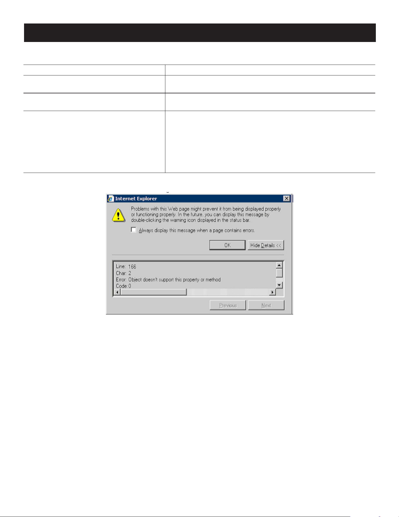
159
8. Troubleshooting
8.2.10 Panel Array Mode
Problem Resolution
Low resolution video – the screens do not
display clearly.
This may occur due to the screens being scaled to t in the panels.
Decrease the number of panels that are displayed.
When multiple remote users are logged in,
some only receive a partial image.
The rst user to invoke Panel Array Mode should set it to display at
least four panels.
When I try to move forward or backward one
port, the display sometimes moves forward
two ports or remains on the original port.
This occurs occasionally due to a net lag problem. The array
automatically moves through the ports at a pre-selected time. By the
time it gets your input It has already moved forward a port on its own
but that has not shown up on your display as yet.
When it moves ahead or back due to your input it appears to have
moved two ports (from its own movement plus your “forward one
port” command) or remains on the original port (from its own forward
movement plus your “back one port” command).
When I open a viewer, the web page does not display or work correctly and I receive an error message that is similar
one of the following:
1. Reset the Internet Explorer security settings to enable Active Scripting, ActiveX controls and Java applets.
By default, Internet Explorer 6 and some versions of Internet Explorer 5.x use the High security level for the
Restricted sites zone and Microsoft Windows Server 2003 uses the High security level for both the Restricted sites
zone and the Internet zone. To enable Active Scripting, ActiveX controls, and Java applets, follow these steps:
a) Start Internet Explorer.
b) On the Tools menu, click Internet Options.
c) In the Internet Options dialog box, click Security.
d) Click Default Level.
e) Click OK.
2. Verify that Active Scripting, ActiveX, and Java are not blocked.
If some client computers work but others do not, verify that Internet Explorer or another program on your client
computer such as an anti-virus program or a firewall are not configured to block scripts, ActiveX controls or Java
applets.
3. Verify that your anti-virus program is not set to scan the Temporary Internet Files or Downloaded Program Files
folders.

160
8. Troubleshooting
4. Delete all the temporary Internet-related files.
To remove all the temporary Internet-related files from your client computer, follow these steps:
a) Start Internet Explorer.
b) On the Tools menu, click Internet Options.
c) Click the General tab.
d) Under Temporary Internet files, click Settings.
e) Click Delete Files.
f) Click OK.
g) Click Delete Cookies.
h) Click OK.
i) Under History, click Clear History, and then click Yes.
j) Click OK.
5. Make sure that you have the latest version of Microsoft DirectX installed.
For information about how to install the latest version of Microsoft DirectX, visit the following Microsoft Web site:
http://www.microsoft.com/windows/directx/default.aspx?url=/windows/directx/downloads/default.htm
6. Make sure that you have the latest version of the Java JRE installed, the Java Web site: www.java.com.
8.2.11 Screen Resolutions Higher than 1280 x 1024
The maximum screen resolution of the B064C-16-1X1-IP’s integrated LCD monitor is 1280 x 1024. To protect it from
being damaged by resolutions that are beyond its display capability, we recommend the screen resolutions of the
connected computers be set to 1280 x 1024 or lower.
If you wish to display screen resolutions higher than 1280 x 1024, follow the procedure described below.
Notes:
• We strongly recommend you close the B064C-16-1X1-IP LCD console before continuing (see 6.1.2 Closing the Console). Using the LCD
monitor to view computers that are set to resolutions that exceed its maximum capability can damage it and shorten its life span.
• To access computers from the external local console when the integrated console is closed, simply connect an external KVM console with
a monitor that supports 1920 x 1200 @ 60 Hz to the B064C-16-1X1-IP’s external console ports.
1. From a remote computer, log in to the B064C-16-1X1-IP and access the computer whose screen resolution you wish
to change.
2. Open the computer’s Control Panel and double-click Display. The Display Properties dialog box will appear.
3. Click the Settings tab, then click Advanced.
4. In the dialog box that appears, click the Monitor tab.
5. Under Monitor settings, click to clear the Hide modes that this monitor cannot display check box.
6. Click Apply.
7. Click the Adapter tab, then click List All Modes. The List All Modes dialog box appears.
8. Under List of valid modes, select the display mode that you want the computer to use.
Note: The maximum screen resolution and refresh rate that the supported for the external local console and remote computers is
1920 x 1200 @60 Hz.
9. Click OK, and then click Apply. The display mode will change to the one you selected.
10. If the Monitor Settings dialog box appears requesting you to confirm the settings change, click Yes.
11. After the Monitor Settings dialog box closes, click OK.
12. In the Display Properties dialog box, click OK.
Repeat these steps for any other computer whose screen resolution you wish to change.
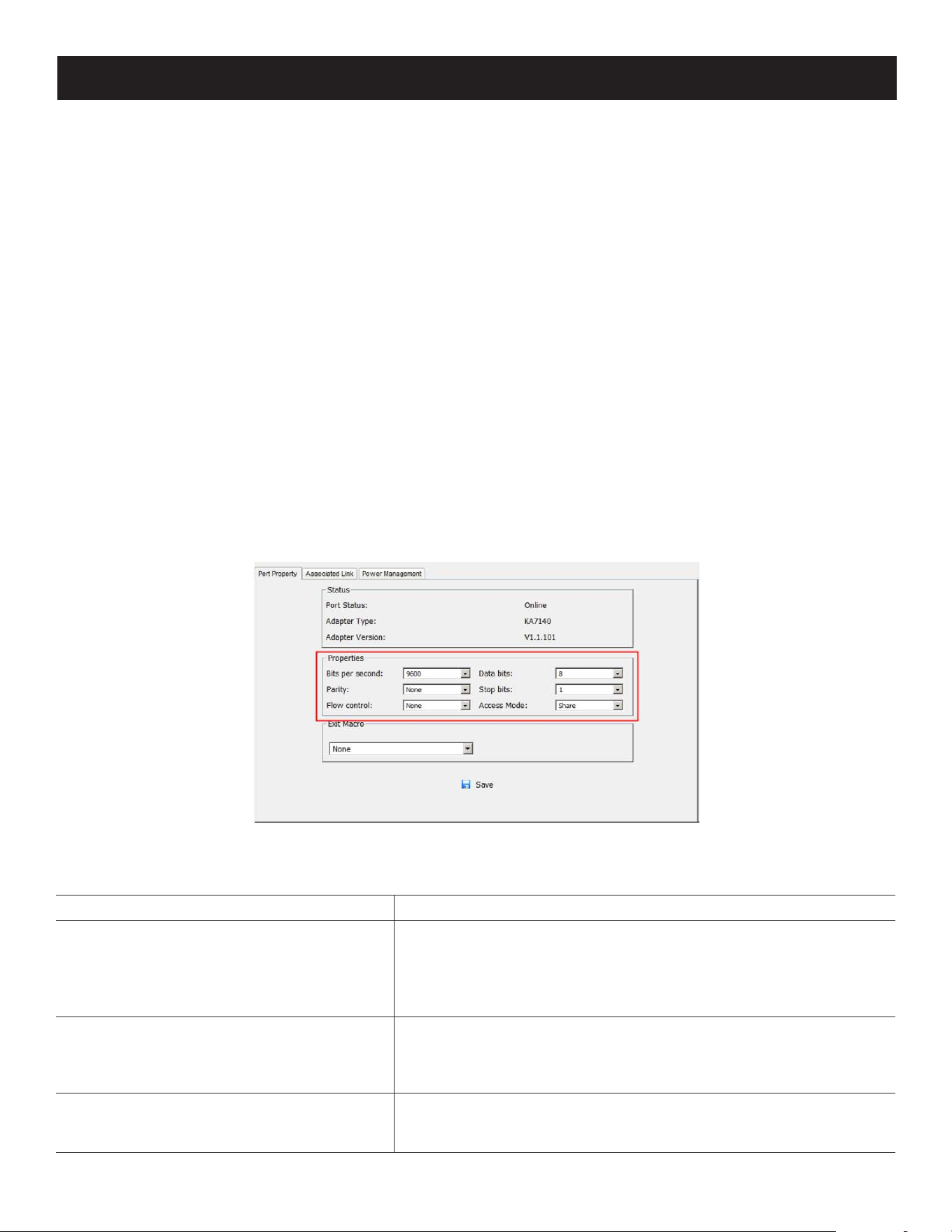
161
8. Troubleshooting
8.3 Port Forwarding
For devices located behind a router, port forwarding allows the router to pass data coming in over a specific port to a
specific device. By setting the port forwarding parameters, you tell the router which device to send the data that comes
in over to a particular port.
For example, if the KVM over IP Switch connected to a particular router has an IP address of 192.168.1.180, you would
log in to your router’s setup program and access the Port Forwarding (sometimes referred to as Virtual Server)
configuration page. You would then specify 192.168.1.180 for the IP address and the port number you want opened for
it (9000 for Internet access, for example).
Since configuration setup can vary somewhat for each brand of router, refer to the router’s User Manual for specific
information on configuring port forwarding for it.
8.4 B055-001-SER Configuration and Operation
The B055-001-SER SIU Adapter Cable connects a serial device to the KVM over IP Switch.
8.4.1 Configuration
To configure the B055-001-SER SIU to interact with the connected device, set its serial parameters to match the
parameters of the device.
1. In the Port Access page Sidebar, select the port that the B055-001-SER SIU is connected to.
2. Select Port Configuration on the menu bar.
A page with the Port Properties tab selected will appear.
3. In the Properties section, use the drop-down lists to select the port property values that match the ones used by the
connected serial console device. The port property settings that the B055-001-SER supports are provided in the
following table:
Setting Meaning
Bits per second (Baud Rate)
This sets the port’s data transfer speed. Choices are from 300-38400
(use the drop-down list to see them all). Set this to match the baud
rate setting of the serial console device.
Default is 9600 (which is a basic setting for many serial console
devices).
Data Bits
This sets the number of bits used to transmit one character of data.
Choices are: 7 and 8. Set this to match the data bit setting of the
serial console device. Default is 8 (the default for the majority of serial
console devices).
Parity
This bit checks the integrity of the transmitted data. Choices are:
None; Odd; Even. Set this to match the parity setting of the serial
console device. Default is Odd.
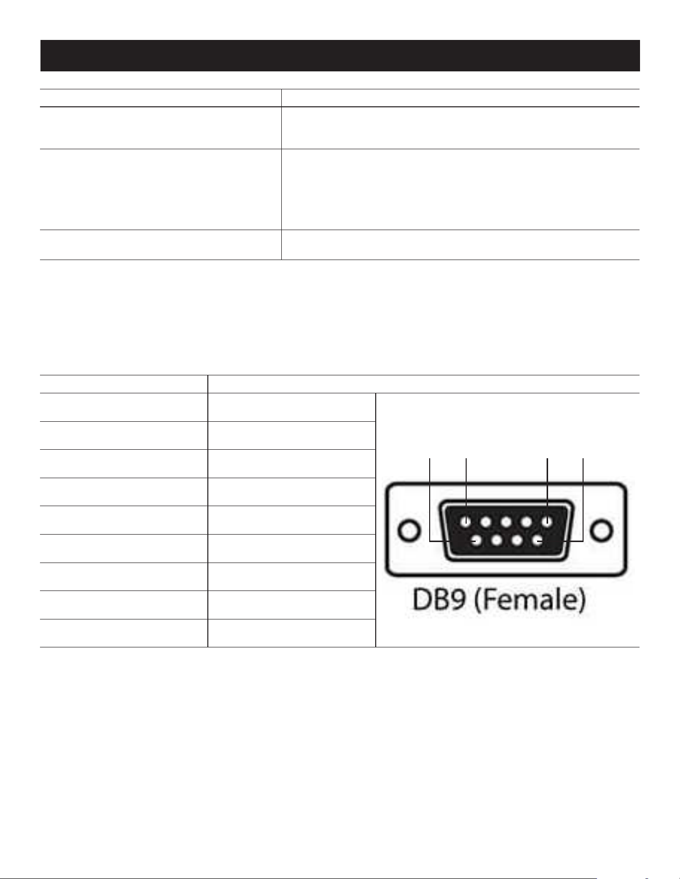
162
8. Troubleshooting
Setting Meaning
Stop Bits
This indicates that a character has been transmitted. Set this to match
the stop bit setting of the serial console device. Choices are: 1 and 2.
Default is 1 (the default for the majority of serial console devices).
Flow Control
This allows you to choose how the data ow will be controlled.
Choices are: None, Hardware, and XON/XOFF. Set this to match the
ow control setting of the serial console device.
Default is None.
Note: None is only supported for baud rates of 9600 and lower. For baud rates
greater than 9600, you must choose Hardware or XON/XOFF.
Access Mode
This allows you to set the serial console device’s access mode. Choices
are: Share, Occupy, and Exclusive. Default is Share.
4. When you have finished making your selections, click Save.
8.4.2 Operation
To operate the device connected to the port, in the Port Access page double-click the port to establish a serial
connection to the device.
8.4.3 B055-001-SER Pin Assignments
Pin Assignment
1 DCD
2 RXD
3 TXD
4 DTR
5 GND
6 DSR
7 RTS
8 CTS
9 N/A
9 5 1 6
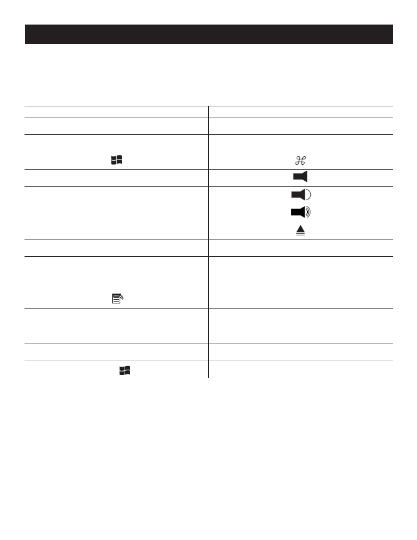
163
8. Troubleshooting
8.5 Keyboard Emulation
8.5.1 Mac Keyboard
The PC compatible (101/104 key) keyboard can emulate the functions of the Mac keyboard. The emulation mappings
are listed in the table below.
PC Keyboard Mac Keyboard
[Shift] Shift
[Ctrl] Ctrl
[Ctrl] [1]
[Ctrl] [2]
[Ctrl] [3]
[Ctrl] [4]
[Alt] Alt
[Print Screen] F13
[Scroll Lock] F14
=
[Enter] Return
[Backspace] Delete
[Insert] Help
[Ctrl]
F15
Note: When using key combinations, press and release the first key (Ctrl), then press and release the activation key.

164
8. Troubleshooting
8.5.2 Sun Keyboard
The PC-compatible (101/104 key) keyboard can emulate the functions of the Sun keyboard when the Control key [Ctrl]
is used in conjunction with other keys. The corresponding functions are shown in the table below.
PC Keyboard Sun Keyboard
[Ctrl] [T] Stop
[Ctrl] [F2] Again
[Ctrl] [F3] Props
[Ctrl] [F4] Undo
[Ctrl] [F5] Front
[Ctrl] [F6] Copy
[Ctrl] [F7] Open
[Ctrl] [F8] Paste
[Ctrl] [F9] Find
[Ctrl] [F10] Cut
[Ctrl] [1]
[Ctrl] [2]
-
[Ctrl] [3]
+
[Ctrl] [4]
[Ctrl] [H]
Help
Compose
Note: When using key combinations, press and release the first key (Ctrl), then press and release the activation key.
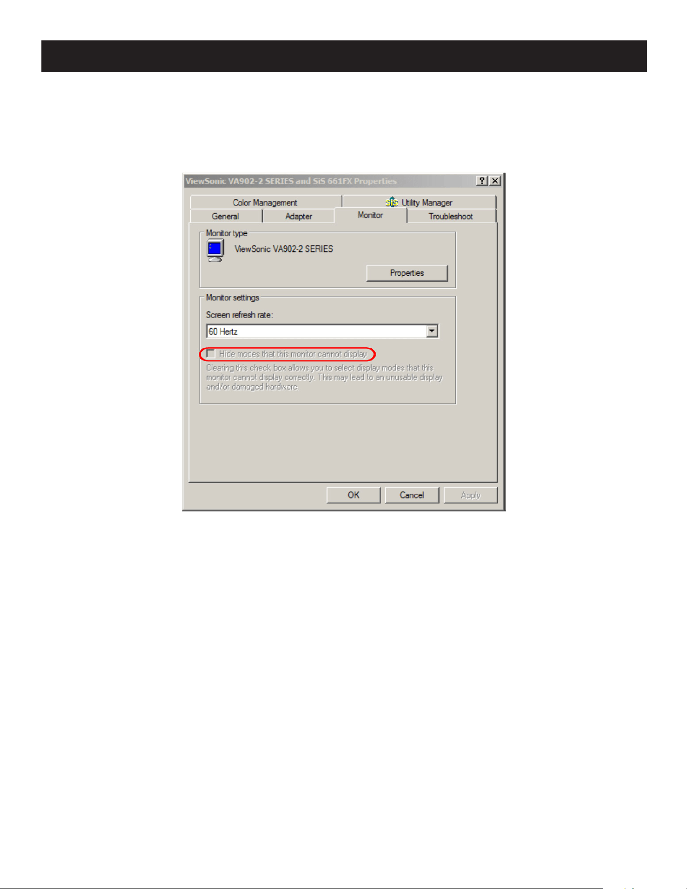
165
8. Troubleshooting
8.6 Additional Video Resolution Procedures
If you are running Windows and wish to use new refresh rates, do the following:
1. Open Control Panel Display Settings Advanced Monitor.
2. In the dialog box that appears, make sure that the Hide modes that this monitor cannot display checkbox is
unchecked.
3. Click the arrow at the right of the Screen refresh rate listbox and select the refresh rate you want from the list that
appears.
Note: Make sure your monitor supports the refresh rate you choose. Otherwise, you may seriously damage your monitor.
8.6.1 Additional Mouse Synchronization Procedures (Windows, Sun, Linux)
If the mouse synchronization procedures mentioned in the manual fail to resolve mouse pointer problems for particular
computers, try the following:
Notes:
• These procedures are to be performed on the computers attached to the B064C-16-1X1-IP’s ports, not on the computer you are using to
access the B064C-16-1X1-IP.
• For the local and remote mice to synchronize, you must use the generic mouse driver supplied with the Windows operating system. If you
have a third-party driver installed (such as one supplied by the mouse manufacturer), you must remove it.
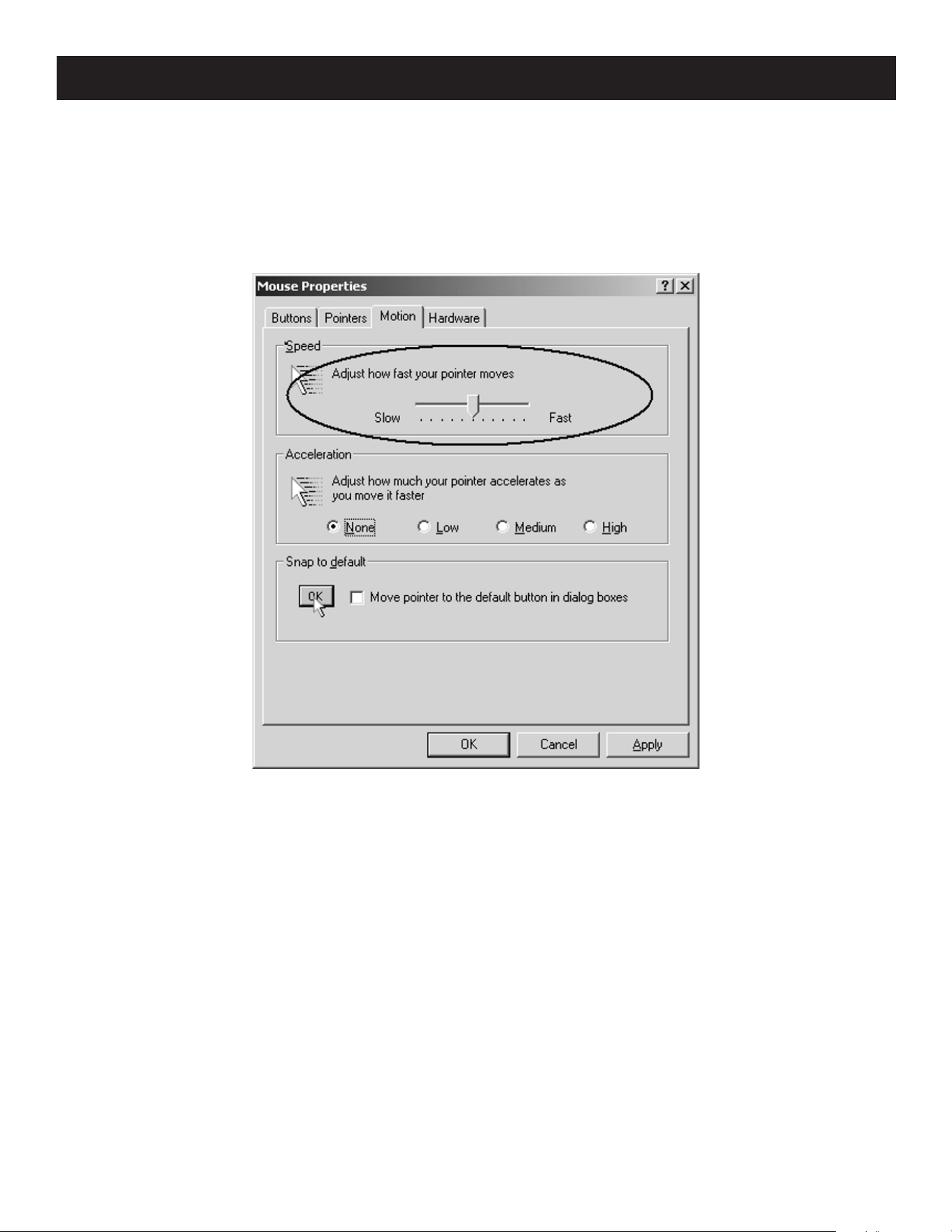
166
8. Troubleshooting
Windows
1. Windows 2000:
a) Open the Mouse Properties dialog box (Control Panel Mouse Mouse Properties)
b) Click the Motion tab.
c) Set the mouse speed to the middle position (6 units in from the left).
d) Set the mouse acceleration to None.
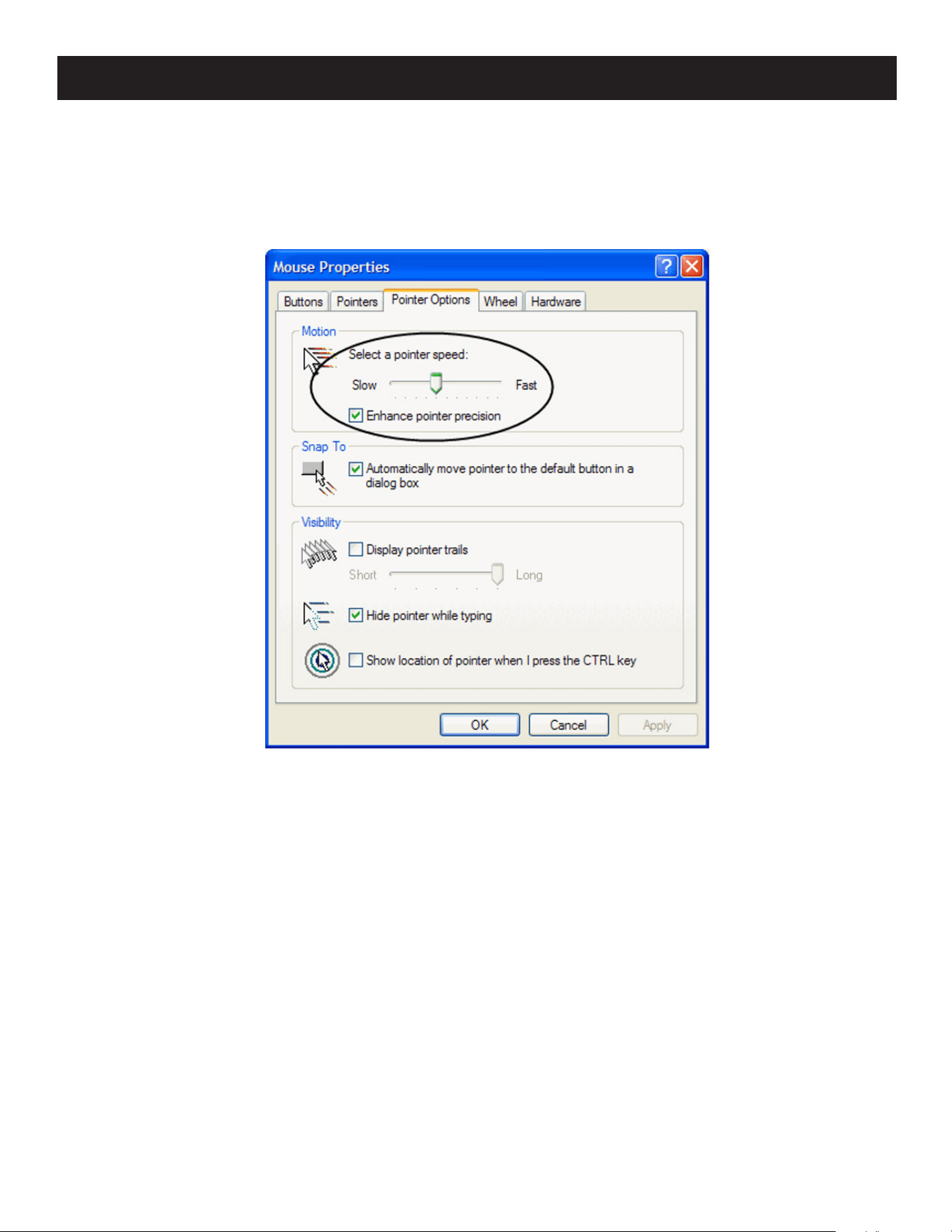
167
8. Troubleshooting
2. Windows XP / Windows Server 2003:
a) Open the Mouse Properties dialog box (Control Panel Mouse)
b) Click the Pointer Options tab.
c) Set the mouse speed to the middle position (6 units in from the left).
d) Disable Enhance Pointer Precision.
3. Windows ME:
Set the mouse speed to the middle position and disable mouse acceleration (click Advanced to get the dialog box).
4. Windows NT / Windows 98 / Windows 95: Set the mouse speed to the slowest position.
Sun / Linux
Open a terminal session and issue the following command:
Sun: xset m 1
Linux: xset m 0
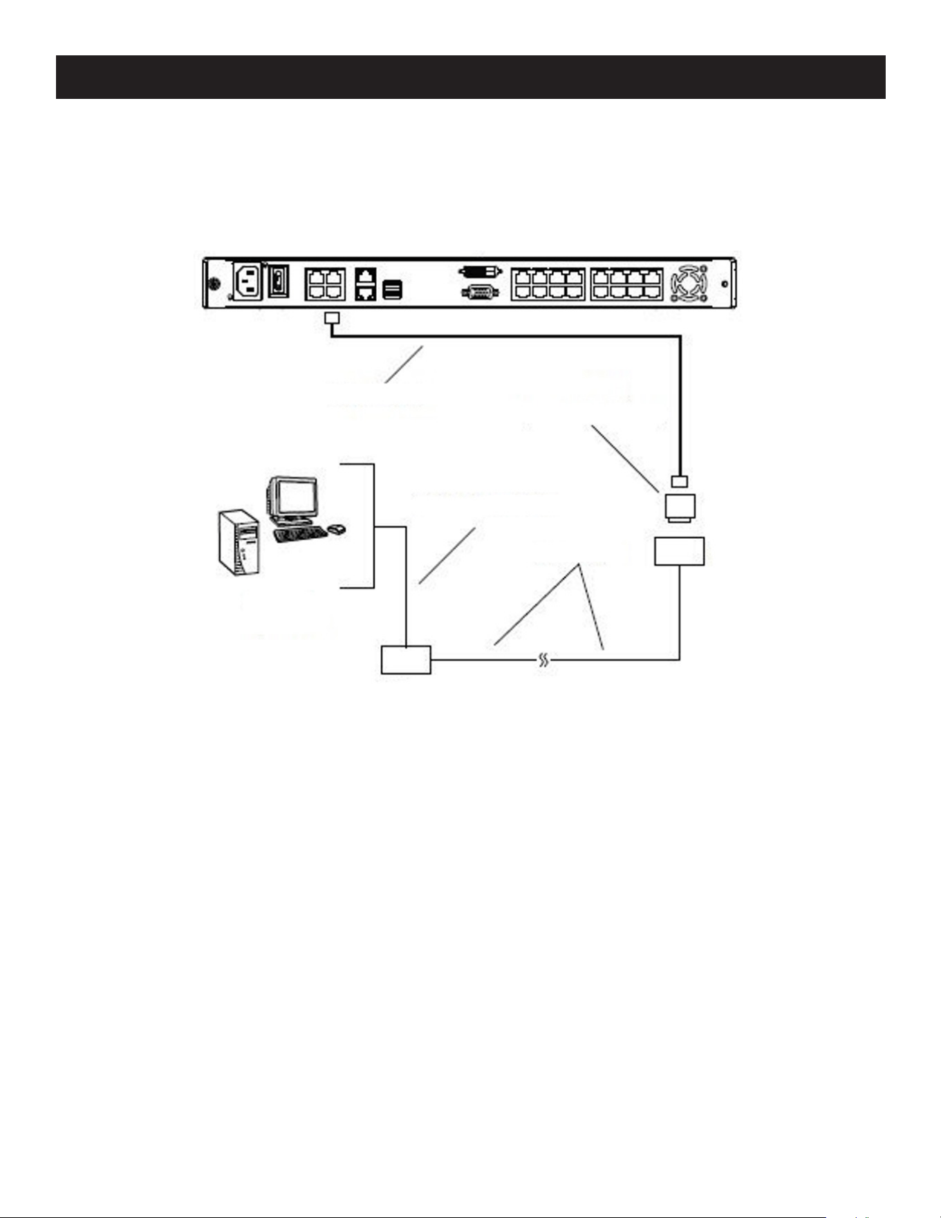
168
8. Troubleshooting
8.7 PPP Modem Operation
8.7.1 Basic Setup
The B064C-16-1X1-IP can be accessed through its serial port using a PPP dial-in connection.
1. Set up your hardware configuration to match the diagram.
2. From your client computer, use your modem dial-in program to dial into the B064C-16-1X1-IP modem.
Note: If you do not know the B064C-16-1X1-IP’s serial parameters, get them from the administrator.
3. Once the connection is established, open your browser, and specify 192.168.192.1 in the URL box.
Notes:
• The default username and password are blank.
• For the modem session, the KVM over IP Switch has an IP address of 192.168.192.1; the user side has an IP address of
192.168.192.101.
From here, operation is the same as if you had logged in from a browser or with the AP programs.
Cat5e cable
DB9-M, DTE-DCE
Serial modem cable
Modem
Phone line
Modem
Remote operator

169
8. Troubleshooting
8.7.2 Connection Setup Example (Windows XP)
To set up a dial-in connection to the B064C-16-1X1-IP under Windows XP:
1. From the Start menu, select Control Panel Network Connections Create a New Connection.
2. When the Welcome to the New Connection Wizard dialog box appears, click Next to move on.
3. In the Network Connection Type dialog box, select Connect to the network at my workplace, then click Next.
4. In the Network Connection dialog box, select Dial-up connection, then click Next.
5. In the Connection Name dialog box, key in a name for the connection (for example, B064C-16-1X1-IP), then click Next.
6. In the Connection Availability dialog box, you can select either Anyone’s use or My use only (depending on your
preferences), then click Next.
Note: If you are the only user on this client computer, this dialog box will not appear.
7. In the Phone Number to dial dialog box, key in the phone number of the modem connected to the KVM over IP
Switch (make sure to include country and area codes, if necessary), then click Next.
8. In the Completing the New Connection Wizard dialog box, check Add a shortcut to this connection on my desktop, then
click Finish.
This completes the connection setup. Double-click the desktop shortcut icon to make a PPP connection to the B064C-
16-1X1-IP.
8.8 Serial Adapter Pin Assignments
SA0142: RJ45-F to DB9-M (Black Connector) DTE to DCE
B064C-16-1X1-IP
(RJ45) Pins (8)
Modem/Device
(DB9)
RTS 1 <————————> 7
DTR 2 <————————> 4
TXD 3 <————————> 3
CTS 4 <————————> 8
GND 5 <————————> 5
RXD 6 <————————> 2
DCD 7 <————————> 1
DSR 8 <————————> 6
9 NC not used
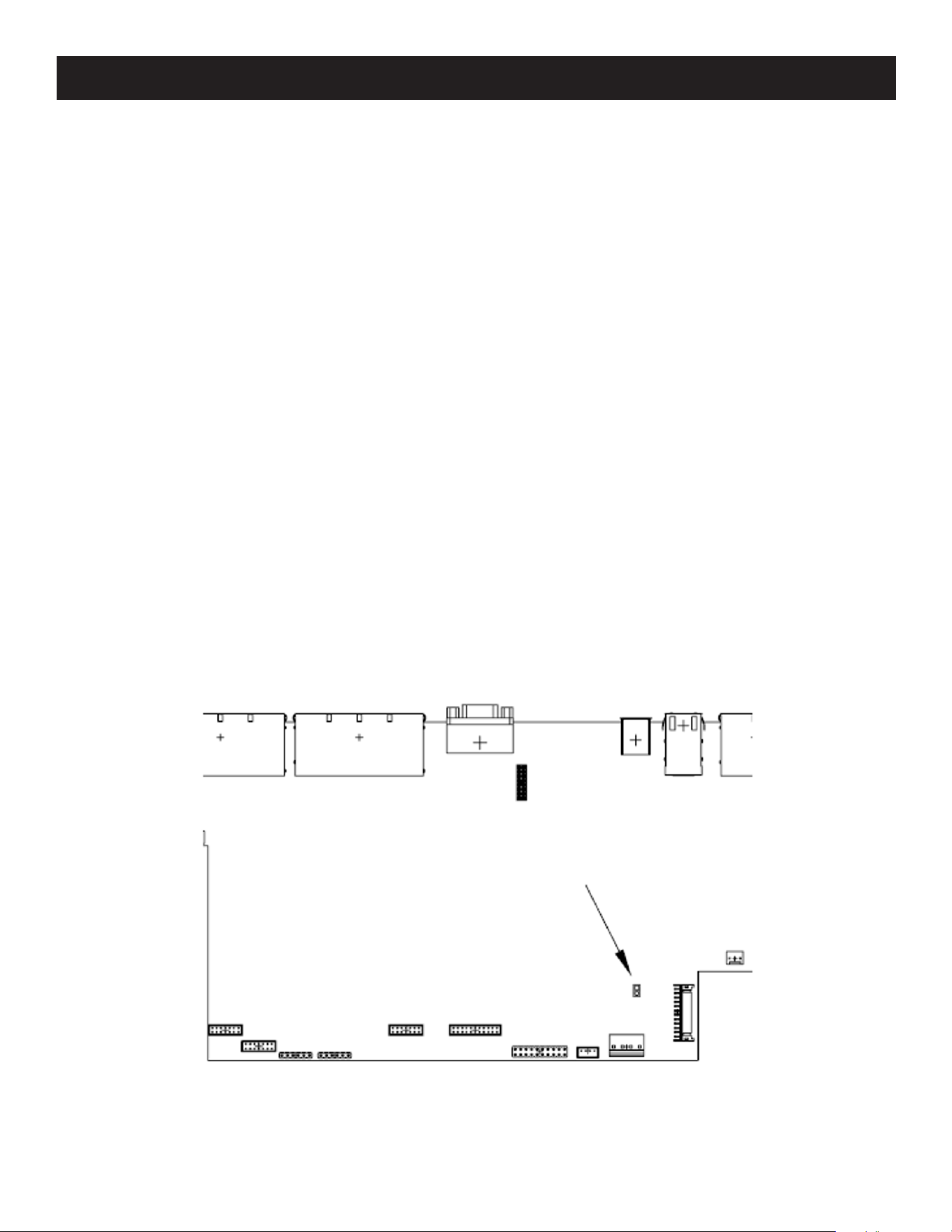
170
8. Troubleshooting
8.9 Virtual Media Support
8.9.1 WinClient ActiveX Viewer / WinClient AP
• IDE CDROM/DVD-ROM Drives – Read Only
• IDE Hard Drives – Read Only
• USB CDROM/DVD-ROM Drives – Read Only
• USB Hard Drives – Read/Write
• USB Flash Drives – Read/Write
• USB Floppy Drives – Read/Write
• Smart Card Readers – Read/Write (B055-001-UDV, B055-001-UHD, B055-001-UDP, B055-001-UV2CAC SIUs only)
Note: These drives can be mounted as a Drive or as a Removable Disk (see 8.2.3 Virtual Media). Removable disks allow the user to boot
the remote server if the disk contains a bootable OS. In addition, if the disk contains more than one partition, the remote server can
access all the partitions.
• ISO Files – Read Only
• Folders – Read/Write
8.9.2 Java Client Viewer / Java Client AP
• ISO Files – Read Only
• Folders – Read/Write
8.10 Administrator Login Failure
If you are unable to perform an Administrator login (e.g., the Username and Password information has become
corrupted or you have forgotten it) you can clear the login information with the following procedure:
1. Power off the B064C-16-1X1-IP and remove its housing.
2. Short the jumper labeled J14.
Default
password
J14

171
8. Troubleshooting
3. Power on the switch.
The on-screen display will show a message informing you that the password information has been cleared.
4. Power off the switch.
5. Remove the jumper cap from J14.
6. Close the housing and restart the B064C-16-1X1-IP.
Once you restart, you can use the default Username and Password (see 7.8 Logging In).
8.11 Factory Default Settings
Setting Default
Language English
OSD Hotkey [Scroll Lock] [Scroll Lock]
Port ID Display Port Number + Name
Port ID Display Duration 3 Seconds
Scan Duration 5 Seconds
Screen Blanker 0 Minutes (disabled)
Beeper On
Viewer Auto Detect
Welcome Message Hide
Accessible Ports
Super Administrators (full for all ports)
All other Users (none for all ports)

172
9. Specifications
Function B064C-16-1X1-IP
Computer
Connections
Direct 16
Max. 256 (via Cascade)
Console
Connections
Local 1
Remote 1
Port Selection OSD, Hotkey, Pushbutton
Connectors
Computer (KVM) Ports 16 x RJ45 Female
Console Ports
Keyboard 1 x USB Type-A Female (White)
Video 1 x HDB-15 Female (Blue) / DVI-D Female (White)
Mouse 1 x USB Type-A Female (White)
LAN 2 x RJ45 Female
Modem 1 x RJ45 Female
Power 1 x IEC 60320/C14
External Mouse Port 1 x USB Type-A Female
Switches
Power 1 x Rocker
LCD Power 1 x Pushbutton
LCD Adjustment 4 x Pushbutton
Port Selection 16 x Pushbutton
Reset 1 x Semi-recessed Pushbutton
LEDs
Port
Online 16 (Green)
Selected 16 (Orange)
Power 1 (Blue)
Lock
Num 1 (Green)
Caps 1 (Green)
Scroll 1 (Green)
10/100/1000 Mbps 2 (10 Mbps: Orange / 100 Mbps: Orange+Green / 1000 Mbps: Green)
LCD Power 1 (Orange)
Emulation Keyboard/Mouse PS/2; USB
Panel
LCD Module 19"
Resolution 1280 x 1024 @ 75 Hz
Response time 5 ms
Viewing Angle 170° (H), 160° (V)
Pixel Pitch 0.294 mm x 0.294 mm
Support Color 16.7M colors
Contrast Ratio 1000:1
Luminance 250 cd/m²
Video 1920 x 1200 @ 60 Hz
Scan Interval 1 - 255 sec.
Input 100 - 240 V AC; 50 - 60 Hz; 1 A
Power Consumption
AC 110 : 32.1 W : 157 BTU
AC 220 : 32.4 W : 158 BTU

173
9. Specifications
Function B064C-16-1X1-IP
Environment
Operating Temperature 32 ~104°F (0 ~ 40°C)
Storage Temperature -4 ~140°F (-20 ~ 60°C)
Humidity 0–80% RH; Non-condensing
Physical
Properties
Housing Metal
Weight 33.66 lb. (15.28 kg)
Dimensions [L x W x H] 18.9 x 27.61 x 1.73 in. (48.00 x 70.12 x 4.40 cm)

174
10. Warranty
1-YEAR LIMITED WARRANTY
We warrant our products to be free from defects in materials and workmanship for a period of one (1) year from the date of initial
purchase. Our obligation under this warranty is limited to repairing or replacing (at its sole option) any such defective products. Visit
Tripplite.Eaton.com/support/product-returns before sending any equipment back for repair. This warranty does not apply to
equipment which has been damaged by accident, negligence or misapplication or has been altered or modified in any way.
EXCEPT AS PROVIDED HEREIN, WE MAKE NO WARRANTIES, EXPRESS OR IMPLIED, INCLUDING WARRANTIES OF MERCHANTABILITY
AND FITNESS FOR A PARTICULAR PURPOSE. Some states do not permit limitation or exclusion of implied warranties; therefore, the
aforesaid limitation(s) or exclusion(s) may not apply to the purchaser.
EXCEPT AS PROVIDED ABOVE, IN NO EVENT WILL EATON BE LIABLE FOR DIRECT, INDIRECT, SPECIAL, INCIDENTAL OR
CONSEQUENTIAL DAMAGES ARISING OUT OF THE USE OF THIS PRODUCT, EVEN IF ADVISED OF THE POSSIBILITY OF SUCH DAMAGE.
Specifically, we are not liable for any costs, such as lost profits or revenue, loss of equipment, loss of use of equipment, loss of
software, loss of data, costs of substitutes, claims by third parties, or otherwise.
Regulatory Compliance Identification Numbers
For the purpose of regulatory compliance certifications and identification, your product has been assigned a unique series number.
The series number can be found on the product nameplate label, along with all required approval markings and information. When
requesting compliance information for this product, always refer to the series number. The series number should not be confused
with the marking name or model number of the product.
WEEE Compliance Information for Customers and Recyclers (European Union)
Under the Waste Electrical and Electronic Equipment (WEEE) Directive and implementing regulations, when customers buy
new electrical and electronic equipment from Eaton, they are entitled to:
• Send old equipment for recycling on a one-for-one, like-for-like basis (this varies depending on the country)
• Send the new equipment back for recycling when this ultimately becomes waste
Warning
Use of this equipment in life support applications where failure of this equipment can reasonably be expected to cause the failure of
the life support equipment or to significantly affect its safety or effectiveness is not recommended.
Eaton has a policy of continuous improvement. Specifications are subject to change without notice. Photos and illustrations may
differ slightly from actual products.

175

176
Eaton
1000 Eaton Boulevard
Cleveland, OH 44122
United States
Eaton.com
© 2024 Eaton
All Rights Reserved
Publication No. 23-09-286 / 93-4800_RevX2
January 2024
Eaton is a registered trademark.
All trademarks are property
of their respective owners.
934800