
1
QB11-W Wireless Button
Install Guide

2
Version
V1.0 20260227
(V1.0 published 20260227)
Firmware
Firmware version can be verified on Verkada
Command command.verkada.com.
Product Models
This install guide pertains to model QB11-W-HW.
Document Details
Document
© Copyright 2026 Verkada Inc. All rights reserved.
Verkada and the Verkada logo are registered trademarks or service marks of Verkada Inc. (“Verkada”). All other trademarks are the
property of their respective owners.
Verkada may make changes to this document at any time without notice. The information presented herein may be inaccurate or
outdated, and Verkada is under no obligation to maintain it. ALL INFORMATION IS PROVIDED “AS-IS” AND WITHOUT ANY WARRANTIES, IMPLIED,
EXPRESS, OR OTHERWISE. VERKADA DISCLAIMS LIABILITY FOR ALL DAMAGES, INCLUDING WITHOUT LIMITATION ANY DIRECT, INDIRECT, SPECIAL,
INCIDENTAL, PUNITIVE, OR CONSEQUENTIAL DAMAGES, ARISING OUT OF USE OF THIS DOCUMENT.
Any intellectual property rights relating to Verkada products are and shall remain Verkada’s exclusive property. Use of any Verkada
product is subject to Verkada’s end user agreement or other executed agreement with Verkada. No license, either expressed or implied,
to use or distribute any Verkada product is granted under this document.
This document may not be sold, resold, licensed or sublicensed and may not be transferred without Verkada’s prior written consent. No
part of this document may be reproduced in whole or in part without the express written consent of Verkada.
3
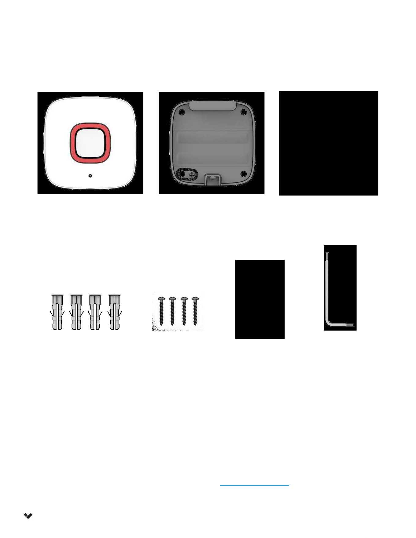
What’s in the Box
Introduction
What you’ll need
● Verkada VLink Hub
● A smartphone or laptop
● A working internet connection
● 1/8 inch (3.2mm) drill bit for pilot holes
● #2 Phillips head screwdriver/driver bit
● Two L91 AA Batteries (included)
Connect
For easy registration and setup, scan the QR
code on the product.
If you prefer to manually register your
product, please proceed to:
verkada.com/start
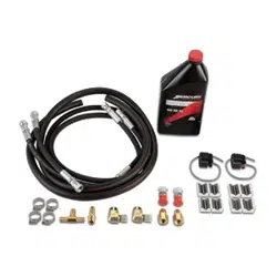
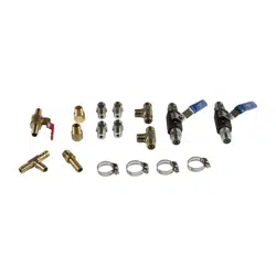
Button Mount Plate
(Attached to device)
Mounting Tape for Button
Wall Anchors (4
pcs)
T10 Security
Torx L-Key
L91 AA Batteries
(2 pcs)
Wood Screws
(4 pcs)
4
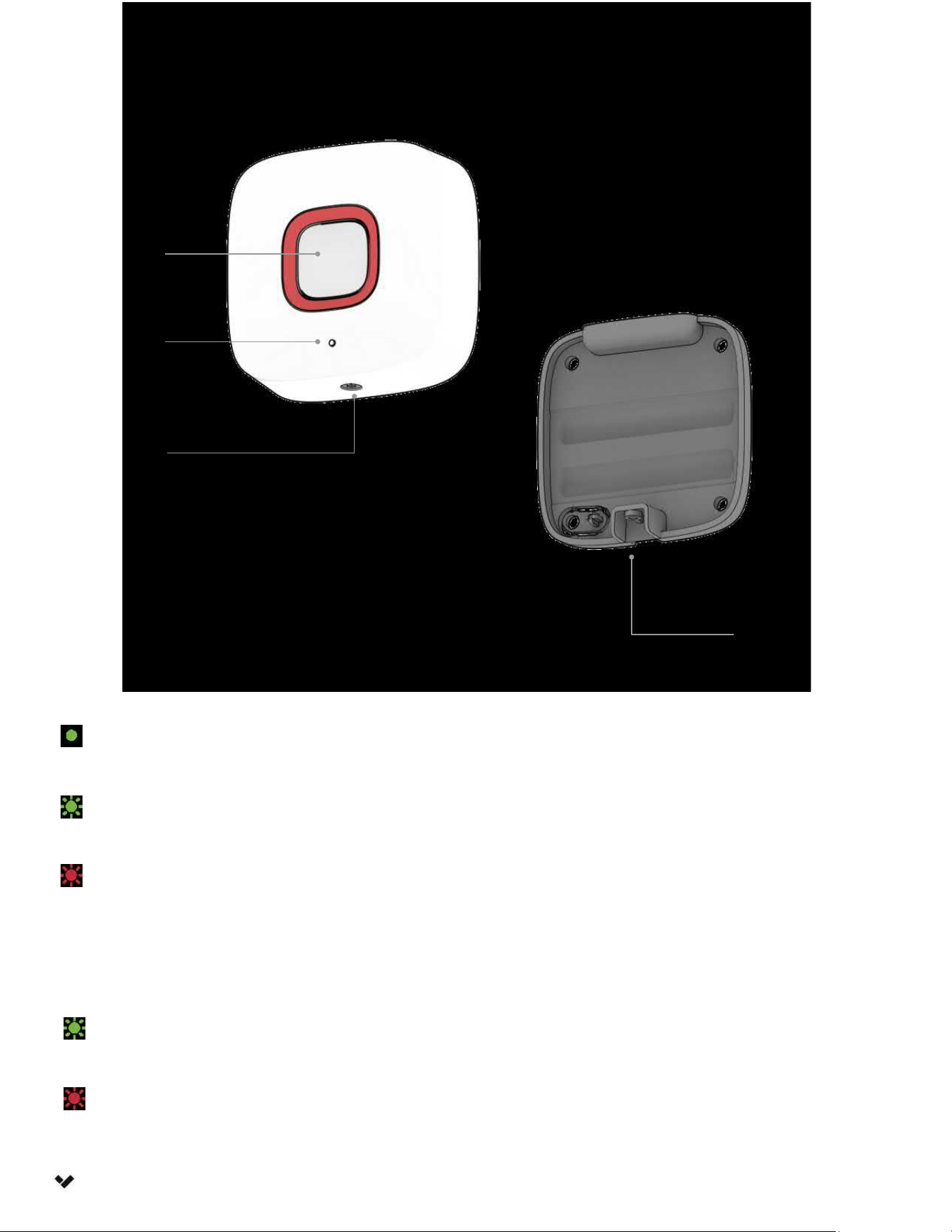
Overview
Introduction
LED Behaviors
Solid Green
Button was pressed and signal was received by hub.
Blinking Amber
Button was pressed, but signal has not been received by hub.
Blinking Red
Button is low on battery.
Button
Security Screw
Mount Plate
Status LED
(Glow Through)
Blinking Green
Button was pressed and signal was received by hub.
Blinking Red
Button was pressed, but signal has not been received by hub.
Install Mode only
To enable Install mode, power cycle the device by removing the battery.

5
Technical Specifications
Introduction
Battery
2x non-rechargeable Energizer Ultimate Lithium L91 AA batteries (included).
*5-year typical battery life.
Connectivity VLink transceiver with internal antenna (863MHz - 928MHz).
RF Range
≥ 2000ft (600m) open field line of sight range when paired with any of Verkada’s
VLink capable hubs (ex: BP32, BP52, BK22, BE32, WH32, WH52).
Tamper Detection Yes, breakaway tab.
Dimensions 2.8in (L) x 2.8in (W) x 1in (H) / 70mm (L) x 70mm (W) x 26.3mm (H)
Weight 3.3oz / 95g
Operating
Temp. & Humidity
32°F-122°F / 0°C-50°C,
0-90% RH non-condensing
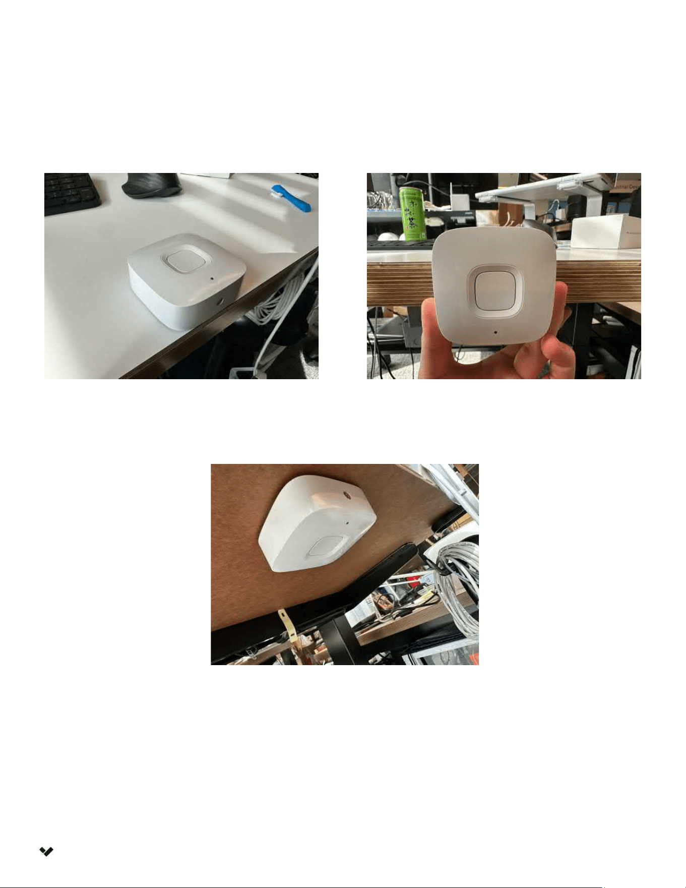
6
Mounting Positions
Introduction
Above surface
Below surface
Side of surface
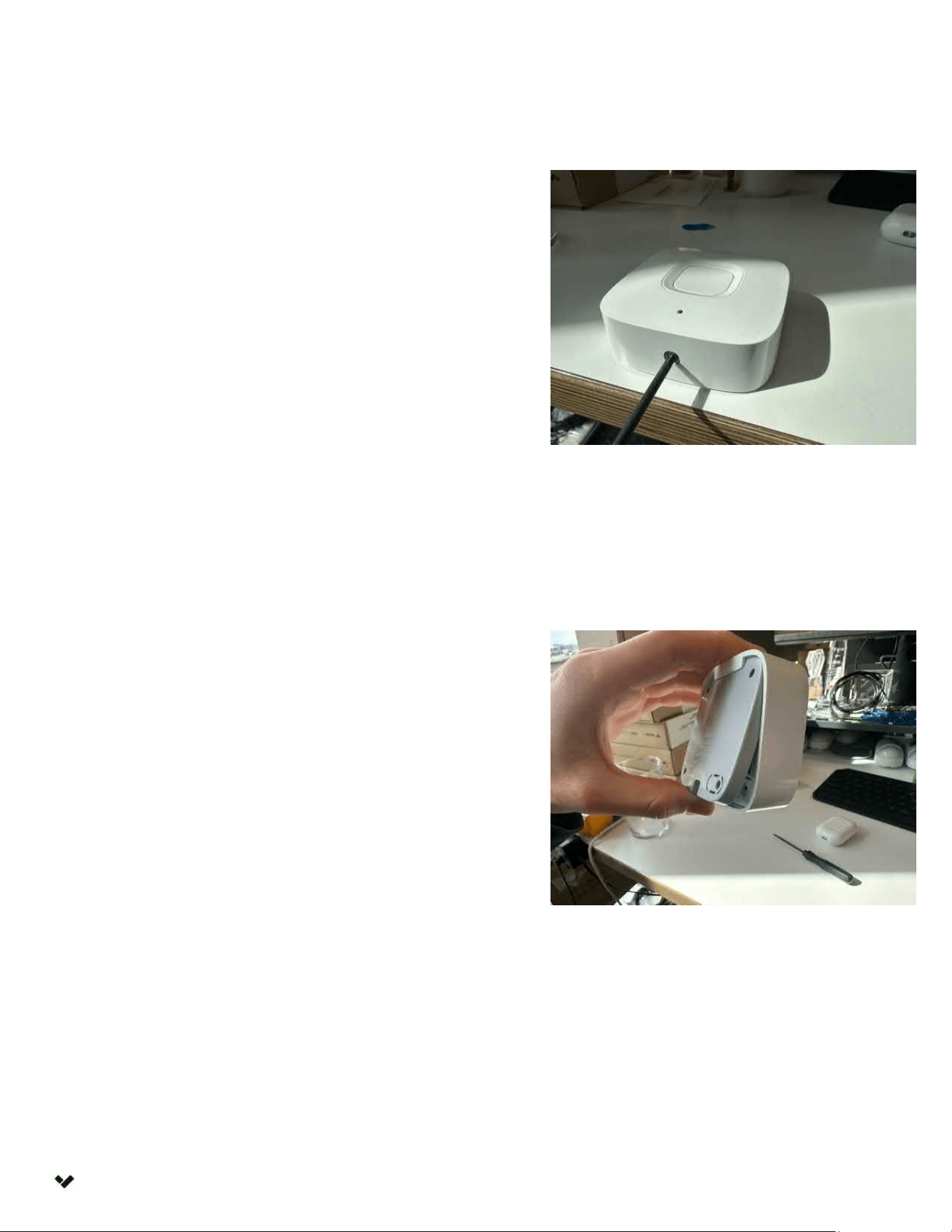
7
Preparation
Use the provided T10 Security Torx
L-key to unscrew the security screw at
the bottom of the product.
Installation
Swing the front of the sensor body away
from the mount plate and disengage the
hook at the top of the sensor mount.
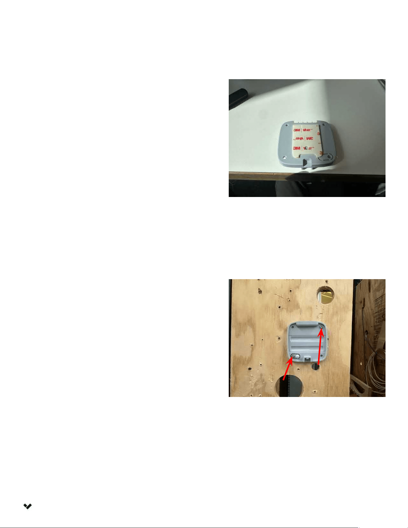
8
Preparation
Installation
Test-mount the sensor to the desired
surface using the included mounting tape.
Remove the sensor body from the
mount plate, use a drill to make
pilot holes, and screw the sensor
mount plate into place.
Note: Screw mounting using the bottom
left screw hole is required for the tamper
detection to function. Using only adhesive
will prevent tamper detection from
triggering properly. The equipment is only
suitable for mounting at heights 2 m or
less.
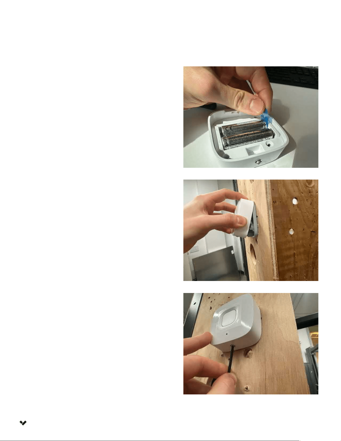
9
Preparation
Remove the battery pull tabs.
Installation
Engage the hook at the top of the
sensor mount and swing the sensor
module into place.
Use the provided T10 Security
Torx L-key to secure the security
screw in place.

10
Compliance
FCC
Compliance
This device complies with part 15 of the FCC Rules. Operation is subject to the following two conditions:
(1) This device may not cause harmful interference, and (2) this device must accept any interference
received, including interference that may cause undesired operation.
NOTE: This equipment has been tested and found to comply with the limits for a Class B digital device,
pursuant to part 15 of the FCC Rules. These limits are designed to provide reasonable protection
against harmful interference in a residential installation. This equipment generates, uses and can
radiate radio frequency energy and, if not installed and used in accordance with the instructions, may
cause harmful interference to radio communications. However, there is no guarantee that interference
will not occur in a particular installation. If this equipment does cause harmful interference to radio or
television reception, which can be determined by turning the equipment off and on, the user is
encouraged to try to correct the interference by one of the following measures:
•Reorient or relocate the receiving antenna.
•Increase the separation between the equipment and receiver.
•Connect the equipment into an outlet on a circuit different from that to which the receiver is
connected.
•Consult the dealer or an experienced radio/TV technician for help.
FCC Caution: Any changes or modifications not expressly approved by the party responsible for
compliance could void the user's authority to operate this equipment.
FCC Radiation Exposure Statement :
This equipment complies with FCC radiation exposure limits set forth for an uncontrolled environment.
This equipment should be installed and operated with minimum distance 20cm between the radiator
& your body. Any changes or modifications not expressly approved by the party responsible for
compliance could void your authority to operate the equipment.
Professional Installation:
This device must be professionally installed. The intended use is generally not for the general public. It is
generally for industrial and commercial use. Installers must be provided with antenna installation
instructions and transmitter operating conditions for satisfying RF exposure compliance and other FCC
rules.
Appendix

11
Compliance
ISED
Compliance
This device complies with ISED’s licence-exempt RSSs. Operation is subject to the following two
conditions: (1) This device may not cause harmful interference, and (2) this device must accept any
interference received, including interference that may cause undesired operation.
Le présent appareil est conforme aux CNR d’ ISED applicables aux appareils radio exempts de licence.
L’exploitation est autorisée aux deux conditions suivantes : (1) le dispositif ne doit pas produire de
brouillage préjudiciable, et (2) ce dispositif doit accepter tout brouillage reçu, y compris un brouillage
susceptible de provoquer un fonctionnement indésirable.
IC Radiation Exposure Statement:
This equipment complies with IC RSS-102 radiation exposure limits set forth for an uncontrolled
environment. This equipment should be installed and operated with minimum distance 20cm between
the radiator & your body.
Déclaration d'exposition aux rayonnements d'IC : Cet équipement est conforme aux limites d'exposition
aux rayonnements IC RSS-102 définies pour un environnement non contrôlé. Cet équipement doit être
installé et utilisé avec une distance minimale de 20cm entre le radiateur et votre corps.
Supported Antennas:
This radio transmitter 26271-60B5901 has been approved by Innovation, Science and Economic
Development Canada to operate with the antenna types listed below, with the maximum permissible
gain indicated. Antenna types not included in this list that have a gain greater than the maximum gain
indicated for any type listed are strictly prohibited for use with this device.
Le présent émetteur radio 26271-60B5901 a été approuvé par Innovation, Sciences et Développement
économique Canada pour fonctionner avec les types d'antenne énumérés ci‑dessous et ayant un gain
admissible maximal. Les types d'antenne non inclus dans cette liste, et dont le gain est supérieur au
gain maximal indiqué pour tout type figurant sur la liste, sont strictement interdits pour l'exploitation de
l'émetteur.
Appendix