Shenzhen MINGDA Technology Co., Ltd.
V2.1
User Manual
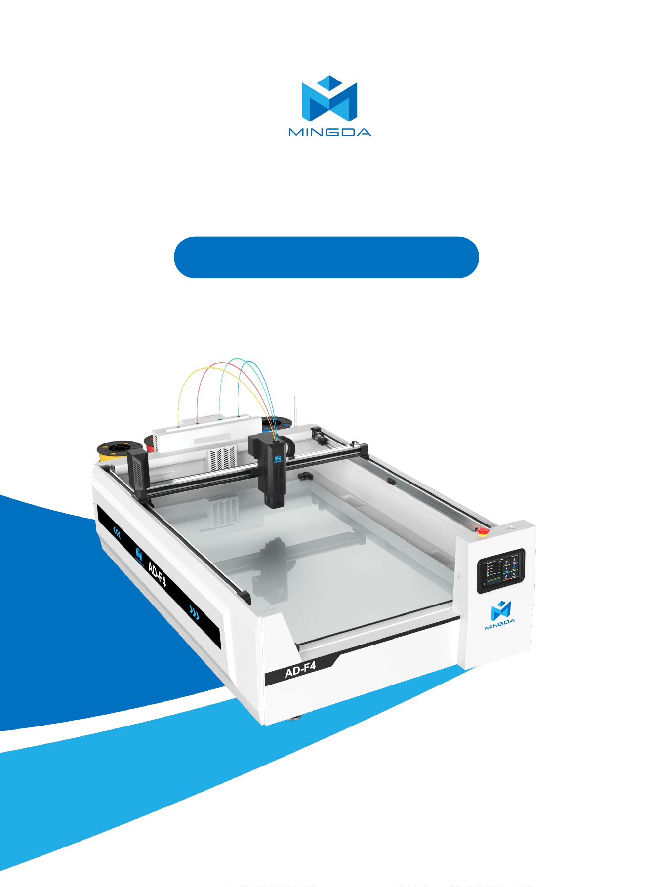
AD-F4 3D Printer
*Please read this guide carefully before using this printer

Thank you for choosing MINGDA Technology!
To ensure the best user experience, please read this manual carefully and follow the instructions
to operate your printer correctly.
If you encounter any issues related to the printer, please refer to the contact information provided
at the end of this manual. Our team is always ready to provide you with professional and timely
support.
To enhance your usage of our product, you can also learn how to use the printer through the
following means:
1. User Manual: Relevant instructions and videos can be found on the included USB drive.
2. You can also visit our official website (www.3dmingda.com) for information on software,
hardware, contact details, device instructions, device specifications, and warranty information,
among other things.
1. Do not place the printer in environments with excessive vibration or unstable surfaces, as this may affect
print quality due to machine shaking.
2. Avoid touching the nozzle or heated bed while the printer is operating, to prevent burns or personal injury
caused by high temperatures.
3. Do not move the printer during the printing process, as this may cause accidents or injury.
4. Do not disassemble the printer or modify its electrical circuits without authorization.
5. Avoid using the printer in high-temperature or high-humidity environments, which may affect its
performance or pose safety risks.
6. In case of emergency, immediately stop using the printer and disconnect the power supply.
Precautions

Content
Precautions----------------------------------------------------------------------------------------------------------------------------------------------------- 01
1. Overview---------------------------------------------------------------------------------------------------------------------------- 02
2. Device Introduction-------------------------------------------------------------------------------------------------------------- 02
Packing list----------------------------------------------------------------------------------------------------------------------------------------------------------03
Product Details---------------------------------------------------------------------------------------------------------------------------------------------------- 04
3. Operating Instructions --------------------------------------------------------------------------------------------------------- 06
Removing the Fixing Device------------------------------------------------------------------------------------------------------------------------------------ 06
Install the Filament Holder----------------------------------------------------------------------------------------------------------------06
Install the PTFE Feeding Tube---------------------------------------------------------------------------------------------------------------------------------- 07
Secure the Material Tray---------------------------------------------------------------------------------------------------------------------------------------- 07
Install the Antenna------------------------------------------------------------------------------------------------------------------------------------------------07
Plug in the Power Socket----------------------------------------------------------------------------------------------------------------------------------------08
Power on/Power off----------------------------------------------------------------------------------------------------------------------------------------------08
Printing Startup ---------------------------------------------------------------------------------------------------------------------------------------------------09
4. Operation Interface Overview-------------------------------------------------------------------------------------------------10
5. Printer calibration --------------------------------------------------------------------------------------------------------------- 15
Z-calibrate---------------------------------------------------------------------------------------------------------------------------------------------------------- 15
Leveling------------------------------------------------------------------------------------------------------------------------------------------------------------- 16
Input shaper------------------------------------------------------------------------------------------------------------------------------------------------------- 16
PID calibrate -------------------------------------------------------------------------------------------------------------------------------------------------------17
6. Load Filament--------------------------------------------------------------------------------------------------------------------- 18
7. Start printing --------------------------------------------------------------------------------------------------------------------- 20
8. Resume printing ----------------------------------------------------------------------------------------------------------------- 21
9. Unload the filament in the extruder --------------------------------------------------------------------------------------- 22
10. Unload the filament in the tube ------------------------------------------------------------------------------------------- 22
11. Slicing Software Installation and Usage ----------------------------------------------------------------------------------23
Installation--------------------------------------------------------------------------------------------------------------------------------------------------------- 23
Configuration------------------------------------------------------------------------------------------------------------------------------------------------------ 23
AdWordCraft-------------------------------------------------------------------------------------------------------------------------------------------------------24
Create text for printing -----------------------------------------------------------------------------------------------------------------------------------------26
Import print file -------------------------------------------------------------------------------------------------------------------------------------------------- 28
Bottom Pattern Settings --------------------------------------------------------------------------------------------------------------------------------------- 29
Side Multi-Color Settings -------------------------------------------------------------------------------------------------------------------------------------- 30
Start the Prime tower------------------------------------------------------------------------------------------------------------------------------------------- 31
Bottom Multi-Color Settings ---------------------------------------------------------------------------------------------------------------------------------- 32
Model Border Parameter Settings--------------------------------------------------------------------------------------------------------------------------- 33
Printing--------------------------------------------------------------------------------------------------------------------------------------------------------------36
Device Connection ---------------------------------------------------------------------------------------------------------------------------------------------- 39
12. Maintenance and Care ------------------------------------------------------------------------------------------------------ 39
2
1. Overview
This manual provides basic instructions for operating and maintaining your 3D printer.
Follow the guidelines to ensure safe use, stable performance, and high print quality.
Thank you for choosing our product!
2. Device Introduction
Device Parameters
Specifications
Product model
AD-F4
Machine dimensions
1110*1730*515mm
Max. build dimensions
1200*800*100mm
Technical principle
FDM (Fused Deposition Modeling)
Layer thickness
0.2-0.42mm
Printing nozzle
4 in 1 out
Number of trays
4 (Max 1KG/Pcs)
Filament diameter
1.75mm
Printing speed
0.4mm nozzle: Max.300mm/s (Recommended 200mm/s)
0.6mm nozzle: Max.150mm/s (Recommended 120mm/s)
Nozzle diameter
0.6mm (optional: 0.4mm, 0.8mm )
Leveling method
Gravity-sensing auto-leveling
Filament types
PLA, Ad-PETG, PDS
Nozzle temperature
Max 350 °C
Hot bed temperature
Max 60 °C
Intelligent design
Filament run-out detection, Power-off resume printing
Maximum power
220V/2700W
Firmware
Klipper
Data connection
USB
Build Plate
Tempered Glass Platform
Filament tray design
Folding filaments tray
Moving speed
Max XY 500mm/s,Max.Z 15mm/s
Safety design
Warning light, Emergency stop button
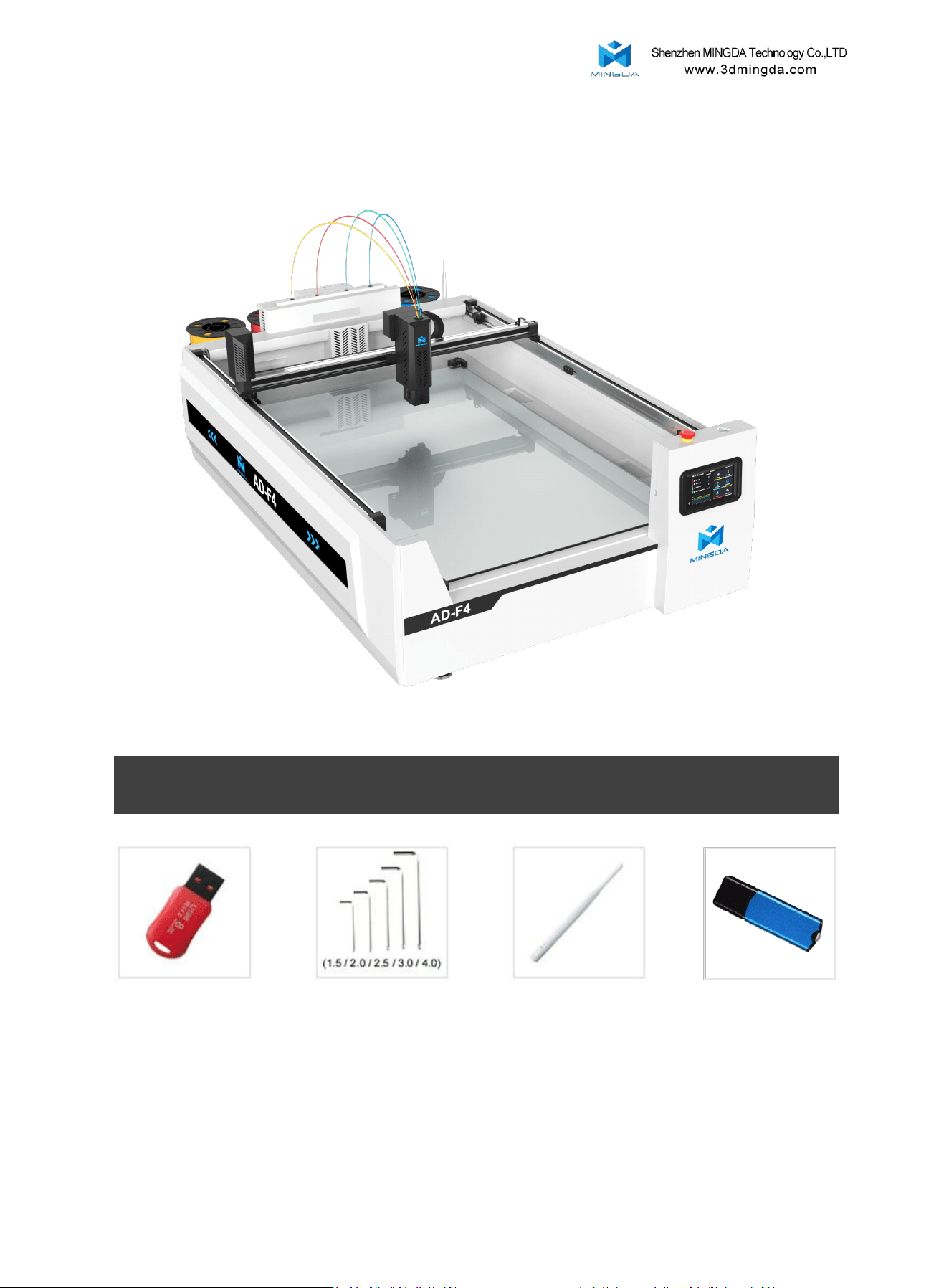
Tool list
3
Packing list
U disk
Allen wrench Antenna
Dongle
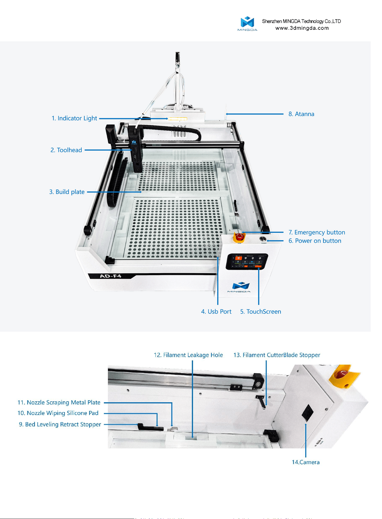
Product Details
4
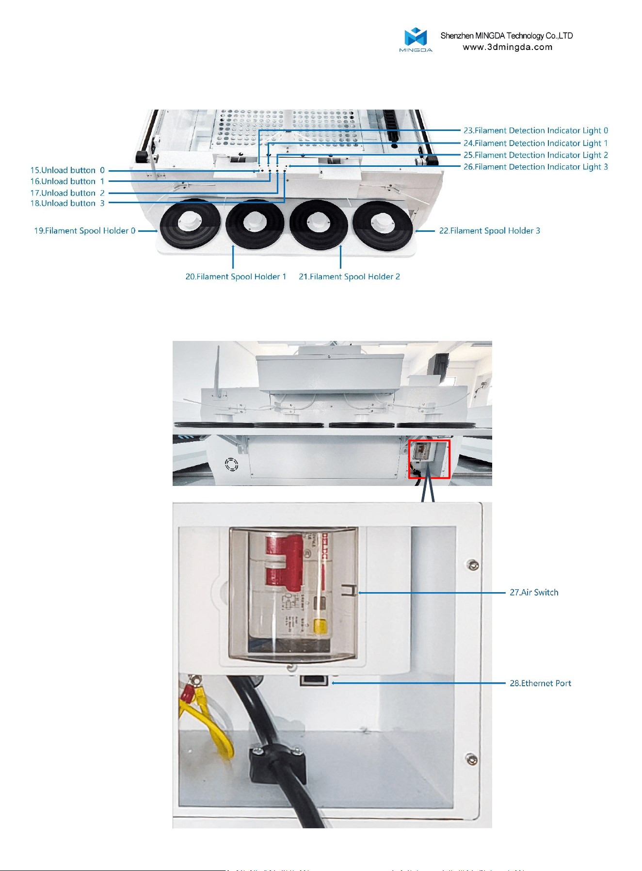
5
Product Details
6
3.Operating Instructions
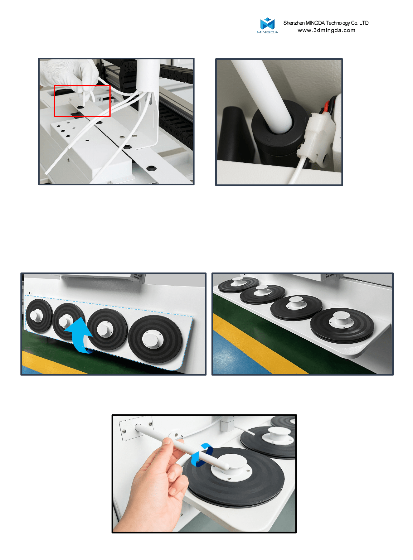
2. Install the Filament Holder
Make sure the filament holder is installed facing outward to ensure proper material
feeding and smooth operation.
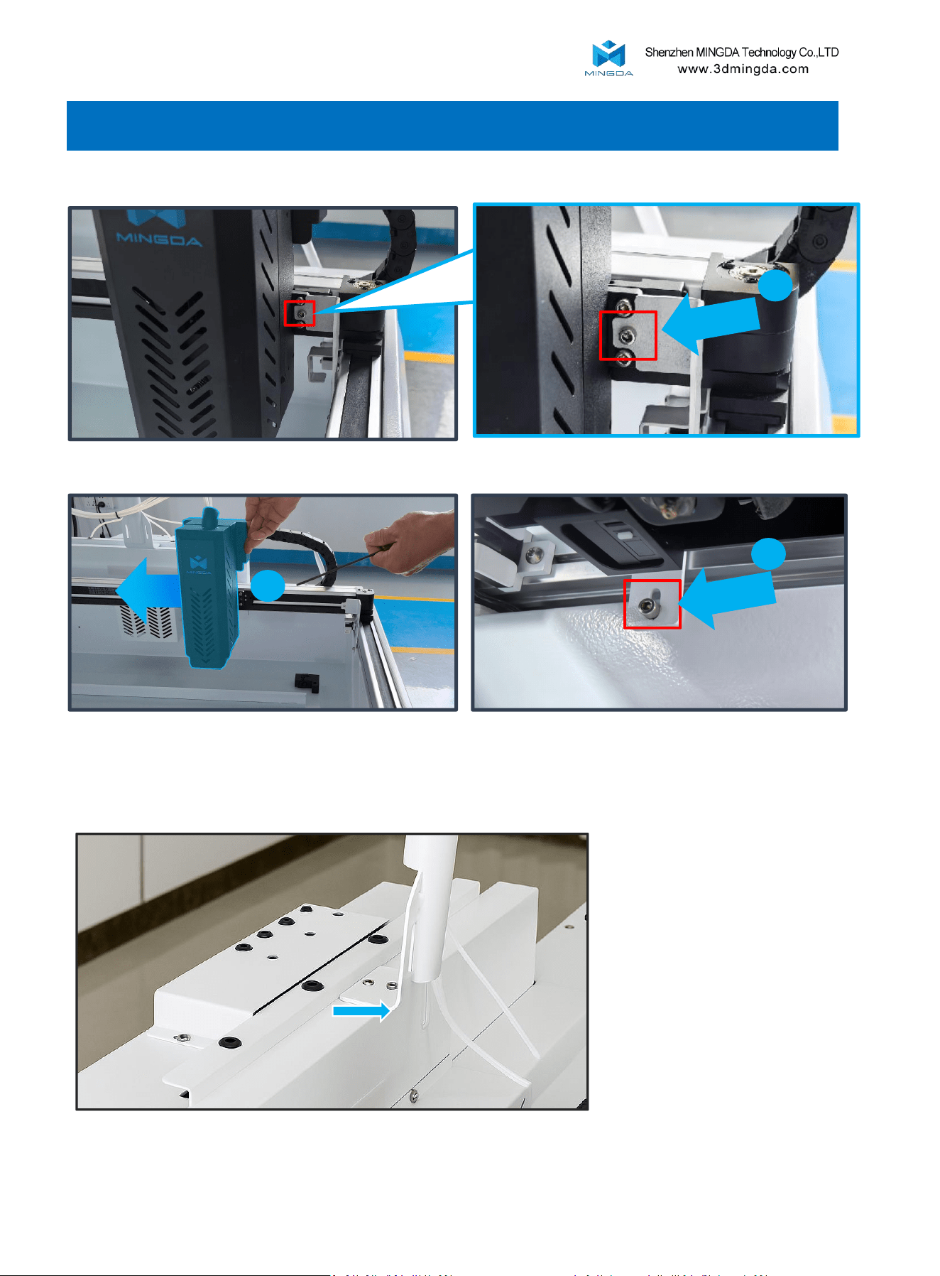
1. Removing the Fixing Device
3
2
1
Then, push the extruder to the left.
First, unscrew the fixing screw next to the extruder
Finally, remove the last screw of the fixing device.
7
4. Secure the Material Tray
Raise the tray from the bottom and firmly fix it in position.
5. Install the Antenna
Instructions:
Insert the PTFE feeding tube one by one. Keep the tube straight during insertion to avoid bending or twisting.
Installation Confirmation:
The tube is properly installed when it cannot be pushed in further. A slight upward pull should not remove it,
indicating the installation is complete.
3. Install the PTFE Feeding Tube
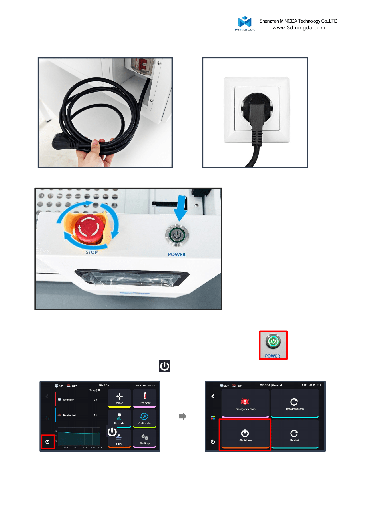
7. Power on
Release the emergency stop
switch, then press the power
button
8
8. Power off
When turning off the printer, do not press the power button directly.
Instead, please click “Shutdown” on the display to properly turn off the printer.
Click shut down to turn off the printer
6. Plug in the Power Socket
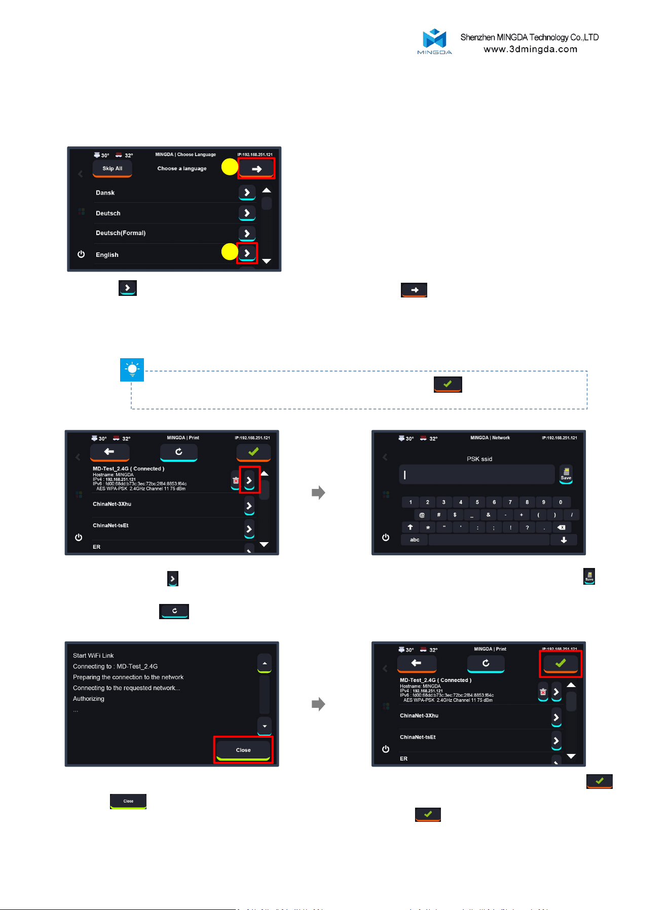
Select Language
Click to select the language, then click to proceed to
the next step.
Wifi
Note: If the printer cannot detect your WiFi, you can click Skip to bypass this step.
After completing the startup wizard, move the router closer to the printer and reconnect.
1
2
Type your Wifi password then click
Select and click (If theWiFi does not
appear within 20 seconds, please
click Refresh.
)
After connecting successfully, click
Enter to go to the main interface.
Or click to continue without a
network connection needed.
Once connected successfully,
click
9
9. Printing Startup
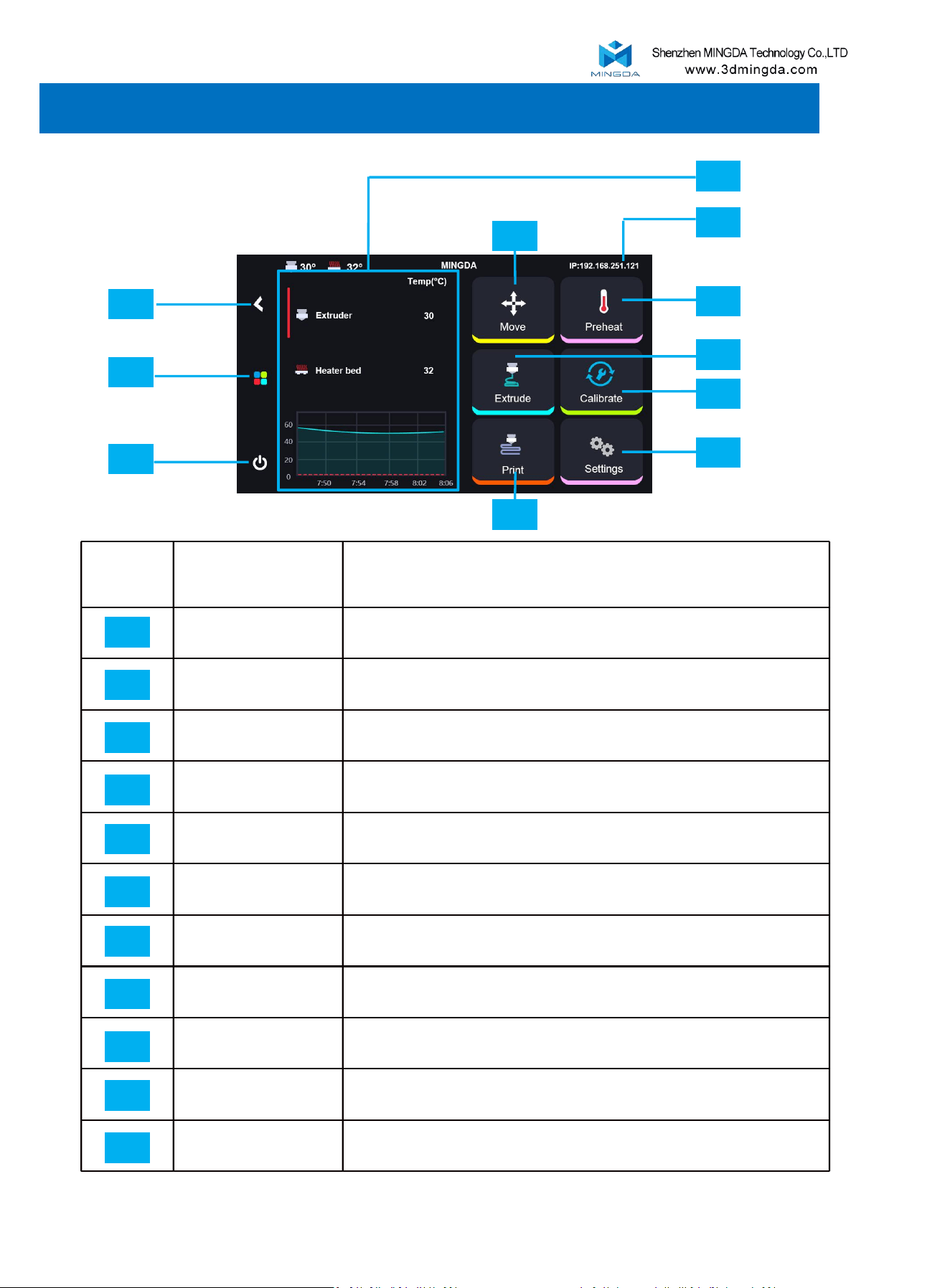
Main menu
11
10
09
01
02
04
05
06
08
07
03
10
4. Operation Interface Overview
Primary interface
Explain
Temperature
Temperature display area.
IP
Network IP address.
Move
Adjust or home the position of the XYZ axis.
Preheat
Pre-set nozzle & hotbed’s temperature.
Extrude
To unload or load the filament.
Calibrate
Printer Calibration.
Settings
Printer's basic setting.
Print
Start printing.
Shutdown
Shutdown, Restart, Emergency stop.
Homepage
Return to the main menu.
Return
Return to the previous page.
01
02
03
04
05
06
07
08
09
10
11
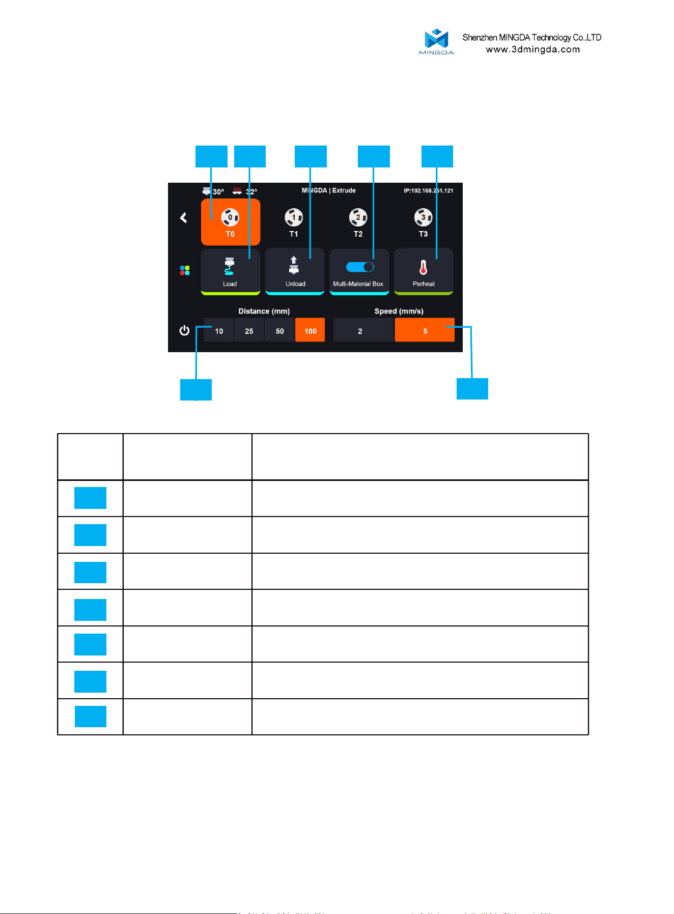
Extrude:
01 02
06
07
03
04
05
11
Secondary interface
Explain
Filament
[T0,T1,T2,T3]; Click to switch to the specified filament
operation interface
Load
Load filament
Unload
Unload filament
Multi-Material Box
Enable multi extruder.
Preheat
Pre-set nozzle & hotbed’s temperature
Distance
Configure the filament loading length for each loading
operation.
Speed
Set up loading or unloading speed
01
02
03
04
05
06
07
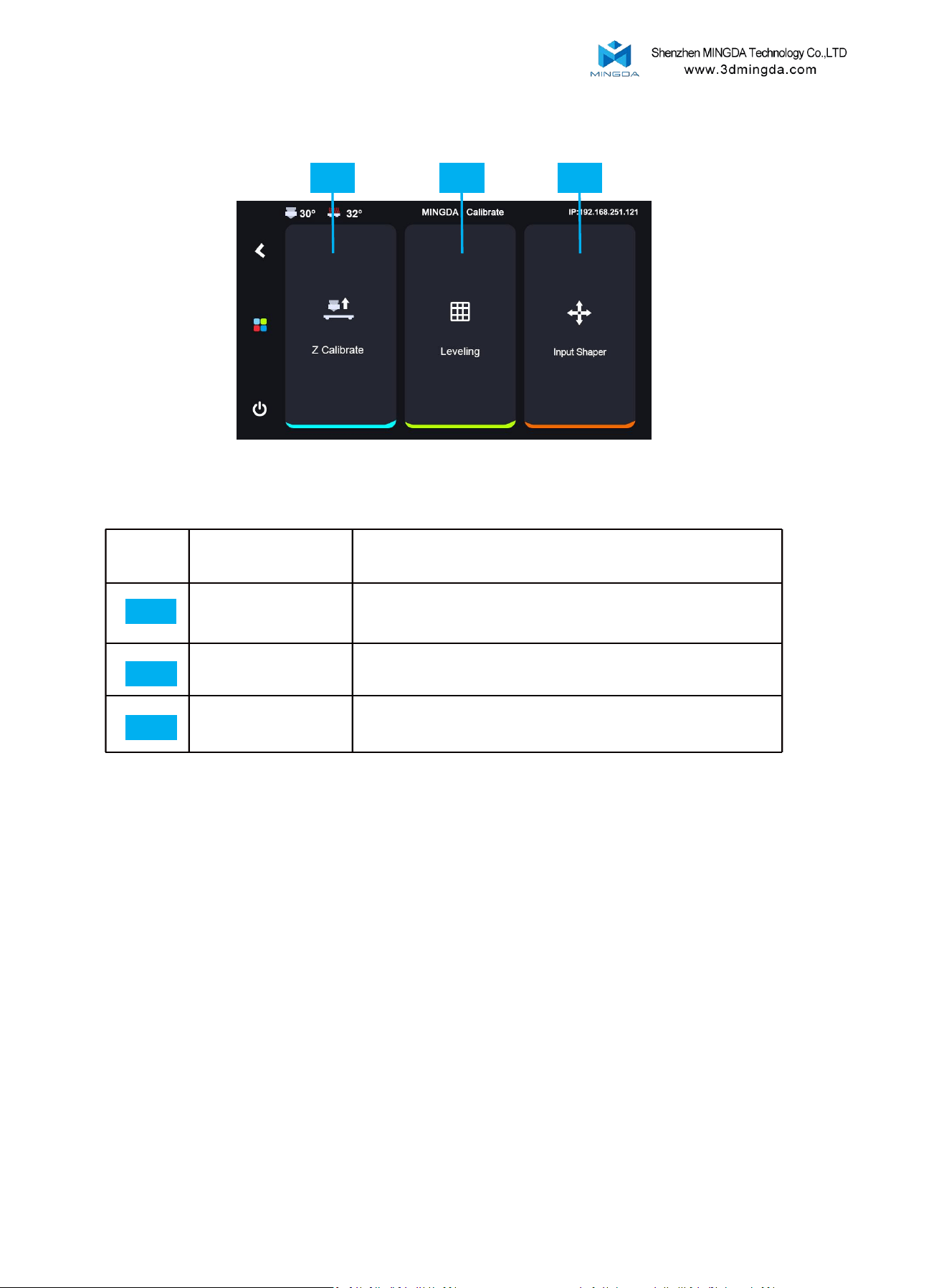
Calibrate:
01 02
03
12
2. Leveling: Before starting the leveling process, heat the bed to
60℃ and wait for 20 minutes. This allows for thermal expansion of
the glass to stabilize, ensuring accurate leveling.
Note:
1. Z-calibrate and Auto-leveling must be performed after replacing
the nozzle, hotend, or removing/reinstalling the extruder.
Printing Tip:
If the bed calibration temperature is set to 60°C. Before printing,
keep the bed temperature at 60°C and wait for 20 minutes to
ensure optimal first layer adhesion and print quality.
Secondary interface
Explain
Z Calibrate
Calibrate the leveling sensor
Leveling
Glass bed Auto-leveling
Input Shaper
Enable vibration compensation
01
02
03
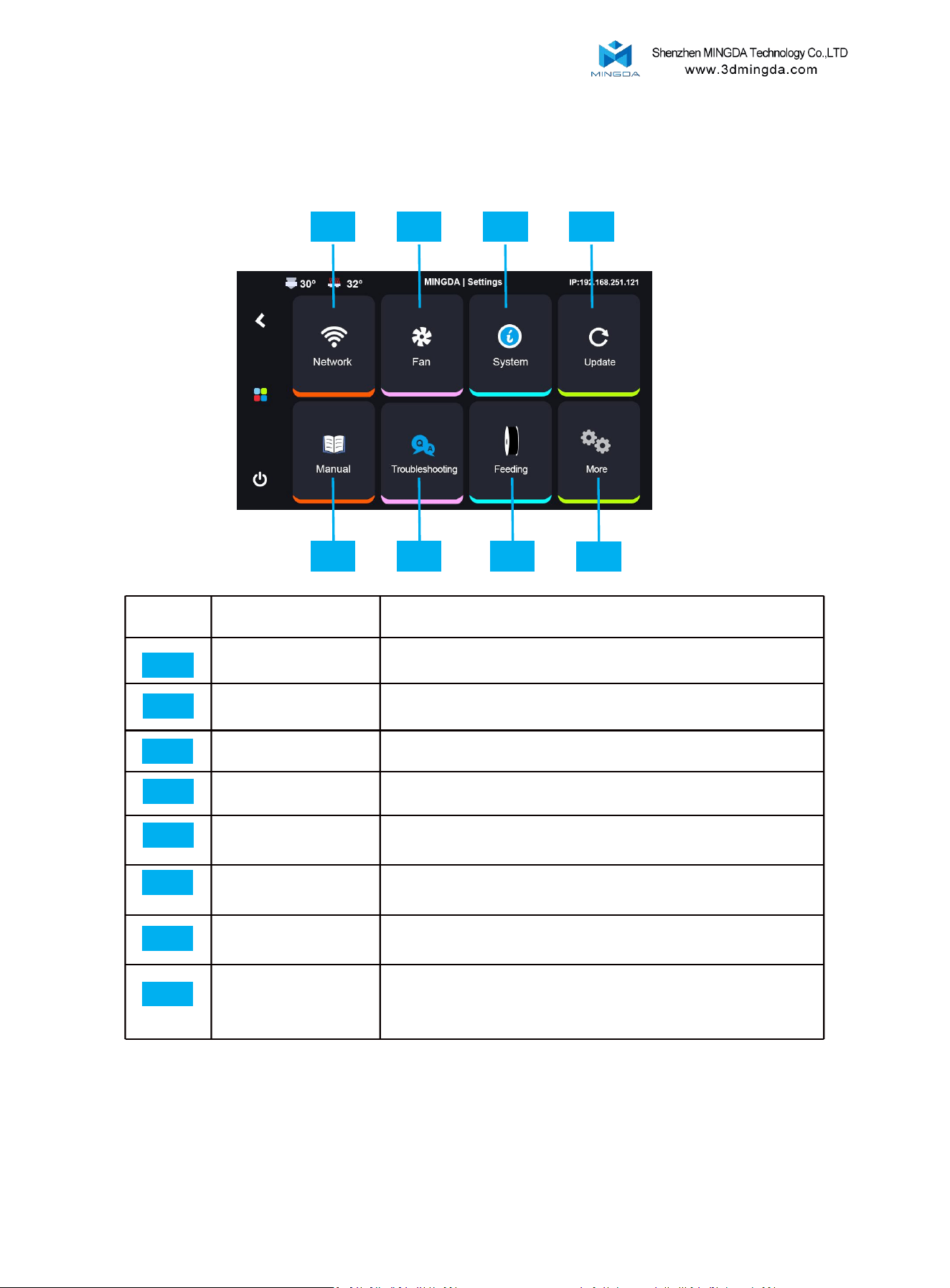
Settings:
05 06
07
01 02
03
04
08
13
Secondary interface
Explain
Network
Connect Wi-Fi
Fan
Cooling fan adjustment
System
Printer's system information
Update
Firmware Update
Manual
Manual
Troubleshooting
Troubleshooting
Feeding
Perform filament parameter settings.
More
Includes some basic settings such as time, language, screen
timeout, notification sound toggle, and automatic shutdown after
printing completion.
01
02
03
04
05
06
07
08
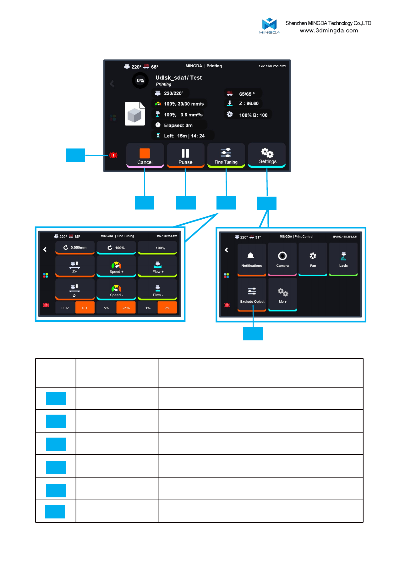
Printing Interface:
01 02
03
Figure 2
Figure 1
05
06
04
14
Secondary interface
Explain
Cancel
Stop printing
Pause
Pause printing
Fine Tuning
Adjust Z-offset, Printing Speed, Printing Flow
[Please refer to Figure 1.]
Settings
Basic setting, browse camera, adjust cooling fan, light and
Exclude object. [Please refer to Figure 2.]
Stop
Emergency stop
Exclude Object
When printing multiple models, you can cancel one of the
printing objects
01
02
03
04
05
06
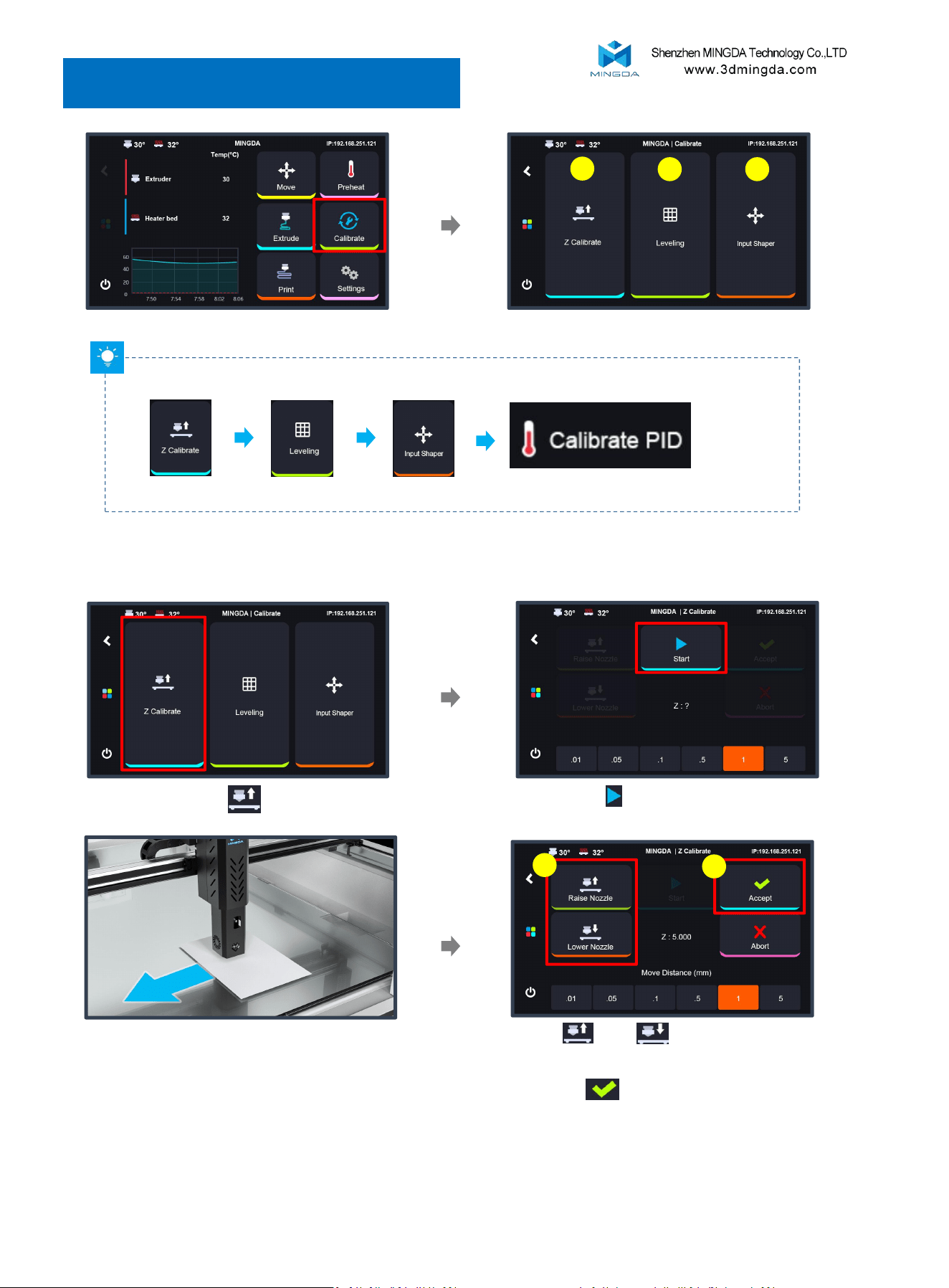
Tip: Follow the diagram step by step to perform the calibration.
1
2 3
5. Printer calibration
Z Calibrate → Leveling → Input Shaper → Calibrate PID
15
1. Z calibrate
Click“ Z calibrate”
Click “Start” and the printer will move
by itself until it stops at the front position
Put An A4 paper between the nozzle and
the platform
Adjust and to make the paper can
be slightly scratched. After moving once, slide
the paper back and forth to check the tension.
Then click to confirm..
1
2
Note:Recalibration must be performed after replacing the nozzle, hotend, or
assembling/disassembling the extruder.
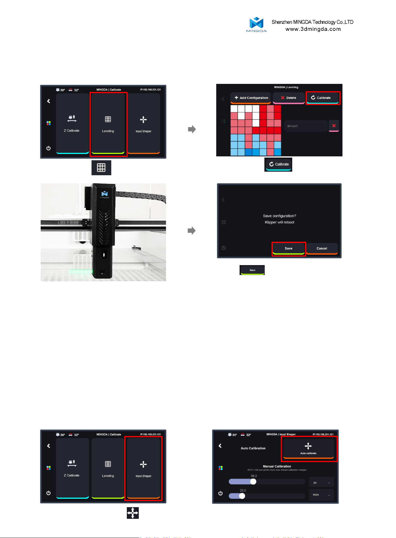
Click to save the value, the
printer will reboot automatically.
Click “ Clibrate”
2. Leveling
Click “Leveling”
Waiting for leveling to complete
(About 15 minutes)
Note:
Make sure the Z calibrate is completed before starting the leveling process.
Before leveling, heat the bed to 60℃ and wait for 20 minutes before proceeding.
16
3. Input Shaper
Click “Input Shaper”
Click “Auto-calibrate” Save it after finishing
Printing Tips:
1. Bed Leveling Frequency:
It is recommended to perform bed leveling every 20–25 print jobs. The Frequent removal
and repositioning of the glass bed can gradually lead to positional deviation. Timely
leveling ensures consistent print quality.
2. How to Determine if Leveling is Needed during printing:
Carefully observe the first layer when starting a new print. If there is a large gap between
the filament and the heated bed, poor adhesion, warping, curling, or uneven extrusion
(e.g., some areas too thick, others too thin, or broken lines), it indicates that bed leveling is
required.
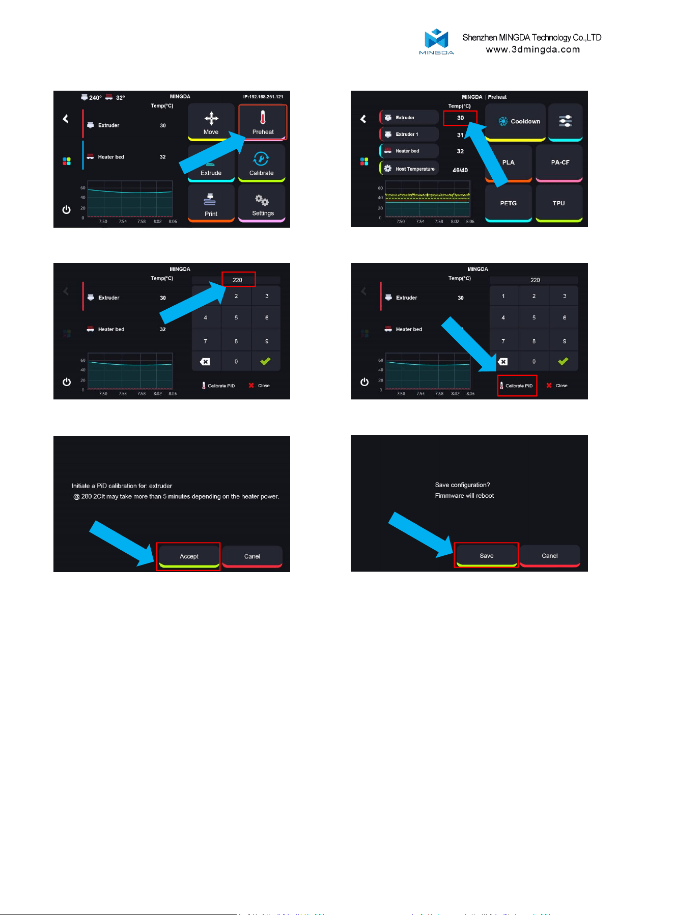
4. PID calibration
Click “Preheat”
Click the temperature value
Set at ”220°C“
Click ”Accept“
Click “Save”
Note:
Before using the machine for the first time, it is essential to perform temperature
calibration.
The nozzle's compensation values must be adjusted according to different ambient
temperatures. Proper calibration ensures accurate and stable temperature control
during printing, thereby improving print quality.
Technical Key Points:
Repeat the PID temperature calibration process multiple times until the nozzle
temperature quickly stabilizes near the target value, with fluctuations within ±2°C.
Since different 3D printing materials require different printing temperatures, it's
important to test the nozzle at typical temperatures for various materials after
calibration to ensure stable temperature control under different printing conditions.
Click “Calibrate PID”
17
6. Load Filament
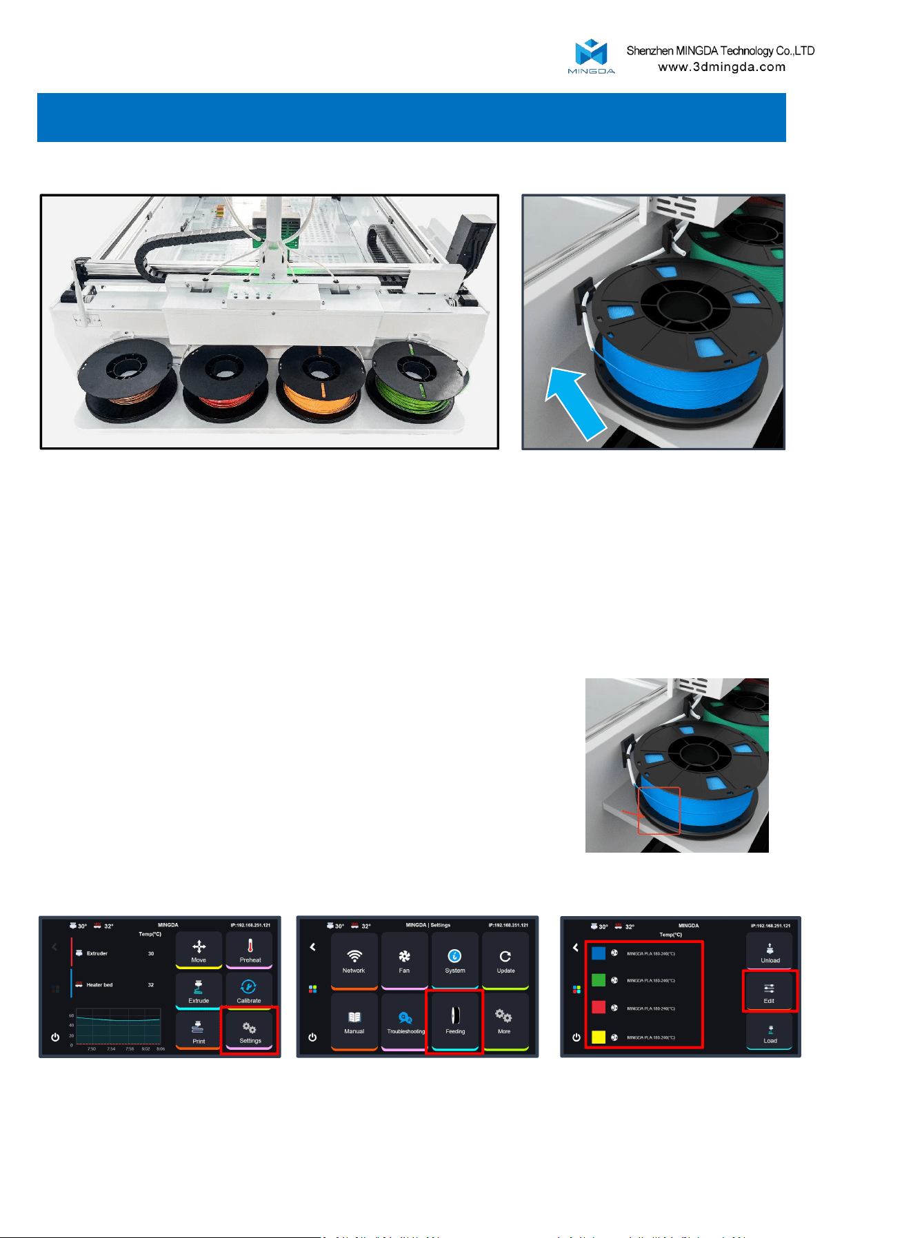
Place the filament onto the material tray.
1. For T0 and T1, the feeding direction is clockwise; for T2 and T3, the feeding direction is
counterclockwise.
2. Insert the filament into the PTFE tube until you feel the extruder begin to pull the filament in,
then release it.
Click the filament and Edit
Click “Settings” Click “Feeding”
3.After loading the filament, you can set the parameters for each material in the screen settings.
Note:
1. During filament loading, make sure the filament remains
taut. Loose filament may get caught in the gaps of the base
plate, causing jams or feeding issues.
2. After completing the loading process for T0, proceed with
T1, and so on in sequence
18
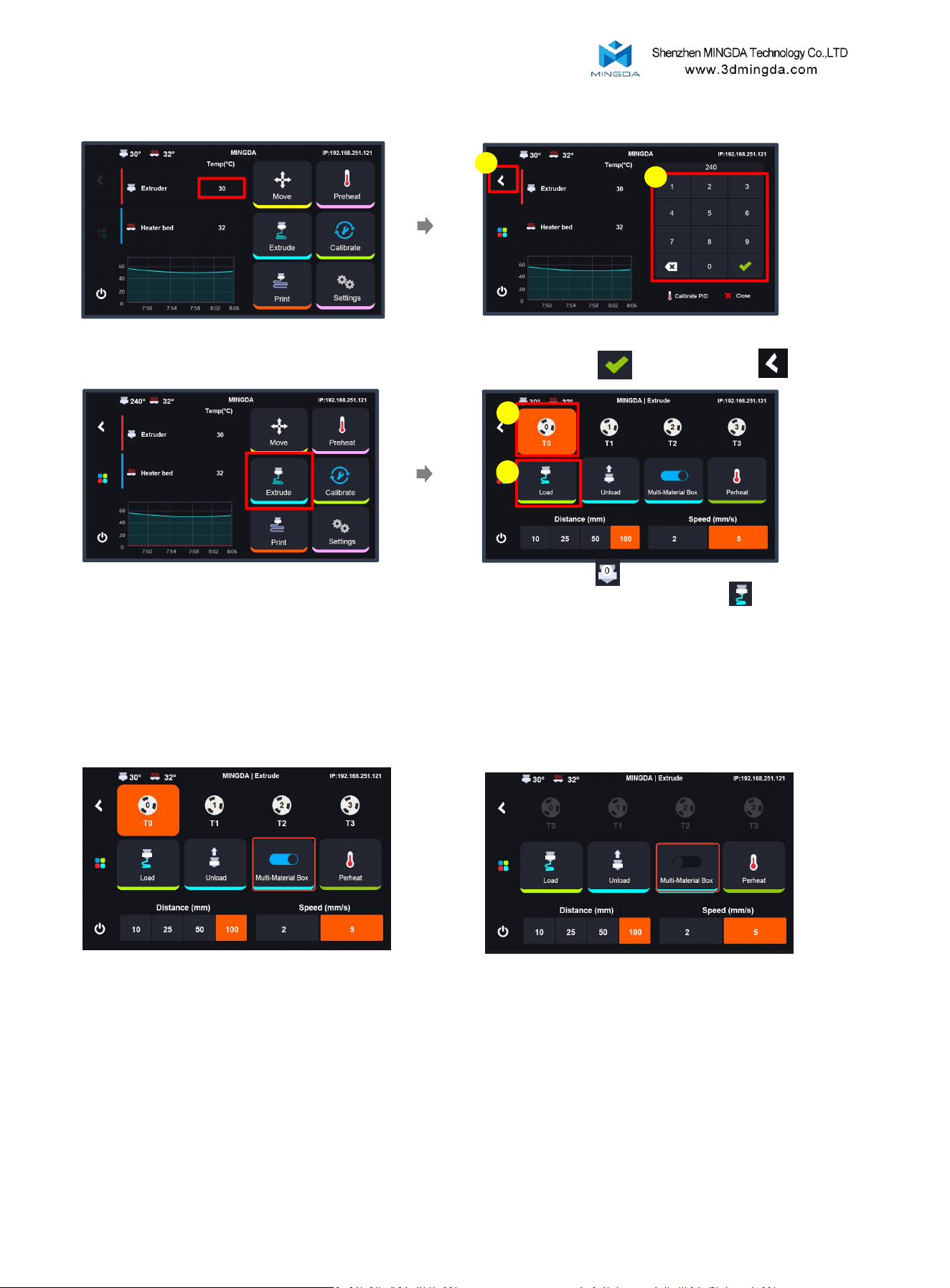
5. Multi Material box
Click "Multi Material box" to print
with four colors.
Turn off the “Multi Material box” the
printer will use external filament.
4. Load filament
1
2
Enter the recommended temperature for the
filament, then click to save and back
Click temperature setting
1
Click “Extrude”
2
Click on extruder set the distance to
100mm and the speed to 5, then click 2–3
times until the filament extrudes from the
nozzle.
19
7. Start printing
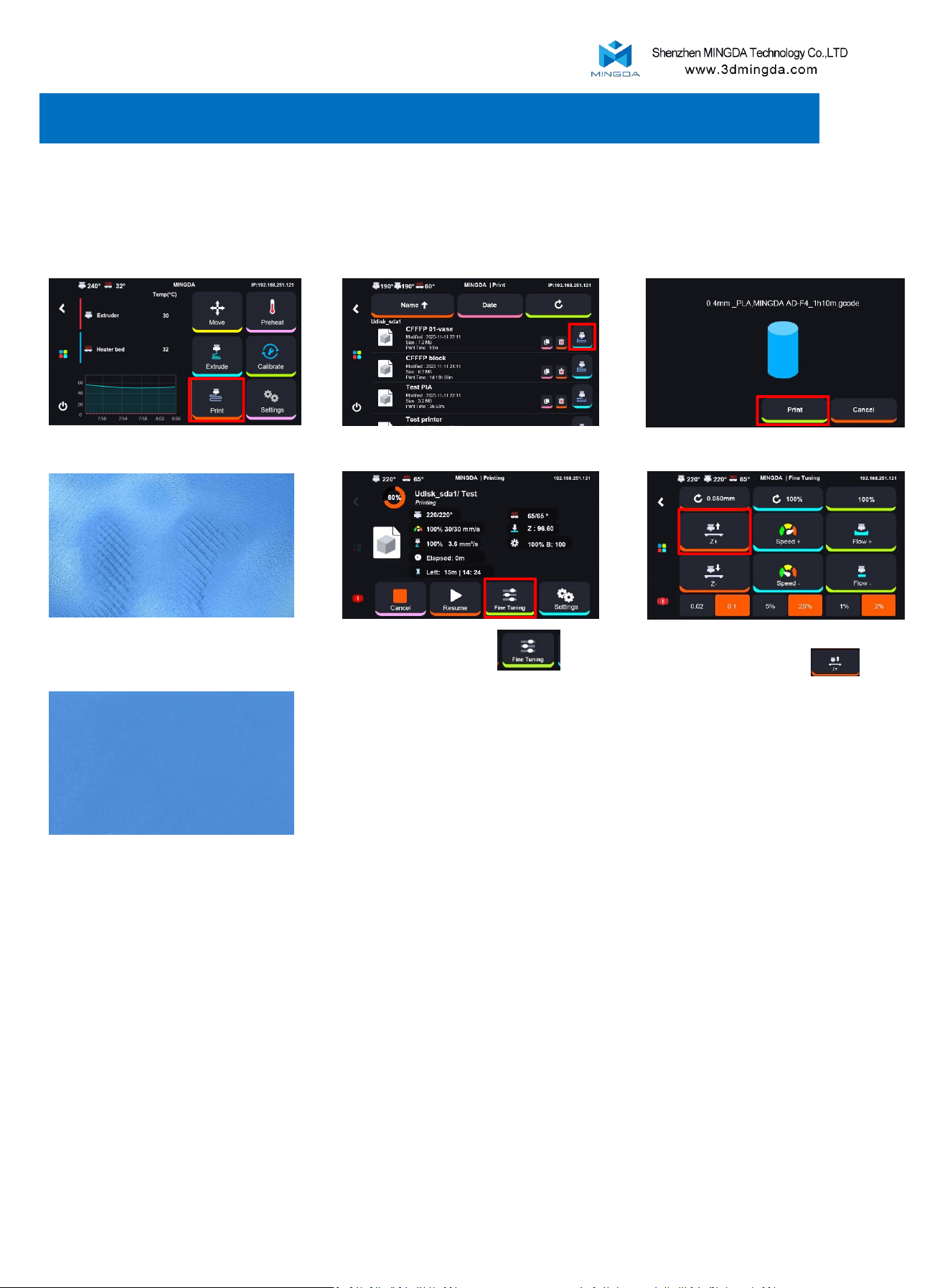
Click “Print”
Click Print icon
After completing the machine setup, click "Print" and select a test
model to quickly start your first print.
Start “Print”
Observe the first layer during printing
Click Fine-tuning
Select the distance at 0.02 and
increase the Z-offset until the
line is smooth
The final result after adjusting
Printing Tips:
During printing, if the model is too close to or too far from the build plate, you can
use the fine-tuning function to adjust the nozzle height:
1. Tap "Fine Tune".
2. Select a tuning step of 0.02, then use Z+ (raise the nozzle) or Z− (lower the nozzle)
to adjust the height until the extrusion lines are evenly laid and properly aligned.
Proper fine-tuning helps achieve optimal first-layer adhesion and print quality.
The first layer very important
1. There are gaps between each lines, that means the Z-offset
need to be lower.
2. There are waves on the printing surface, that means the Z-
offset need to be higher
Tips:
20
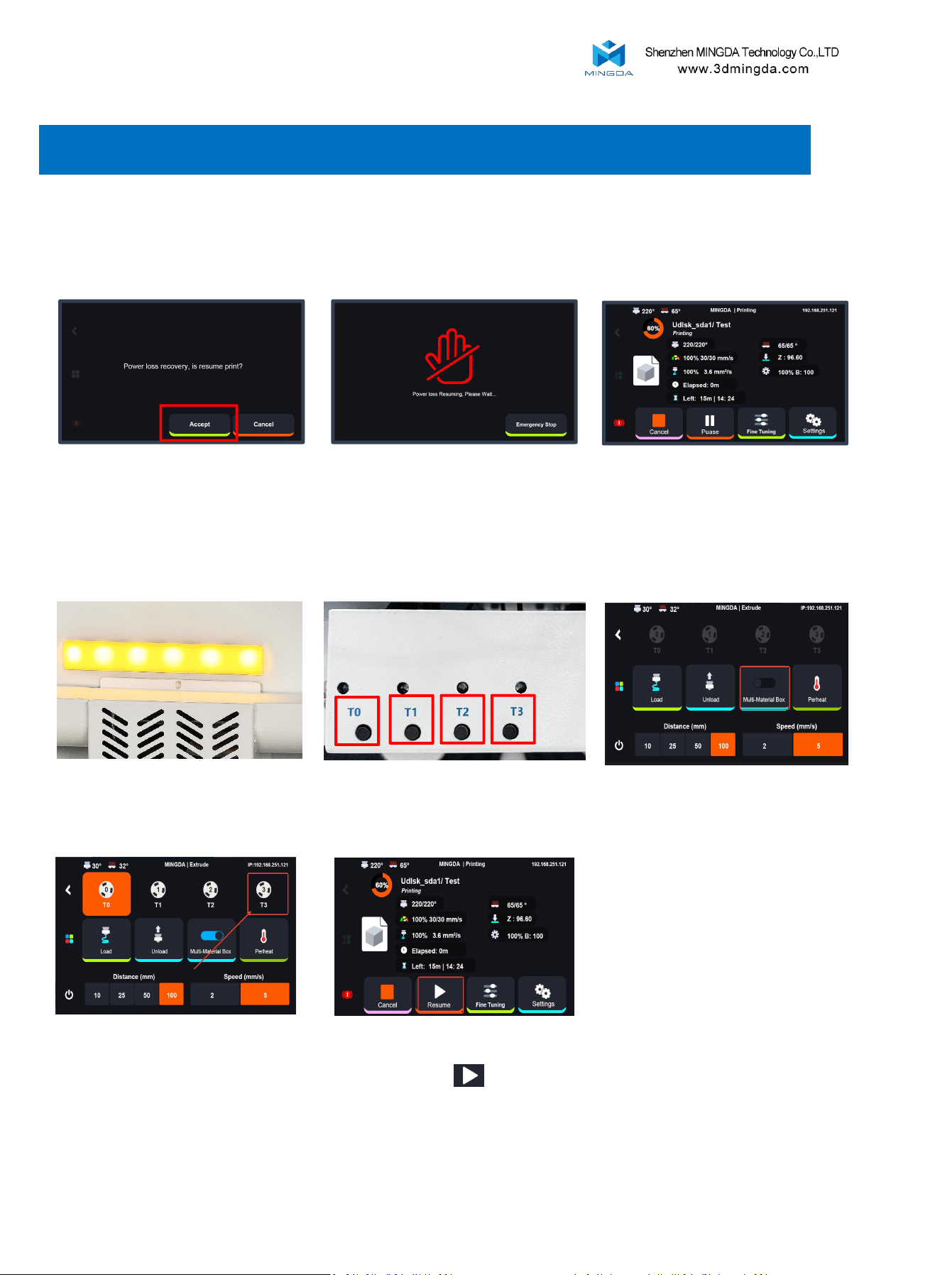
Wait for 30 seconds while the machine automatically
loads the filament.
Then click “Resume” to continue printing.
2. Resume printing after filament used off
Printing paused — yellow light
alarm activated
The pop-up will show up after
power back, click Accept to resume
print.
Waiting for the reume printing.
The AD-F4 features a resume printing function that allows you to effortlessly continue your
print job from the point where it was interrupted.
1. Resume printing after power off
8. Resume printing
Please check which green
light is off. For example T3
Select T3
After insert the filament, click Multi
Material Box
21
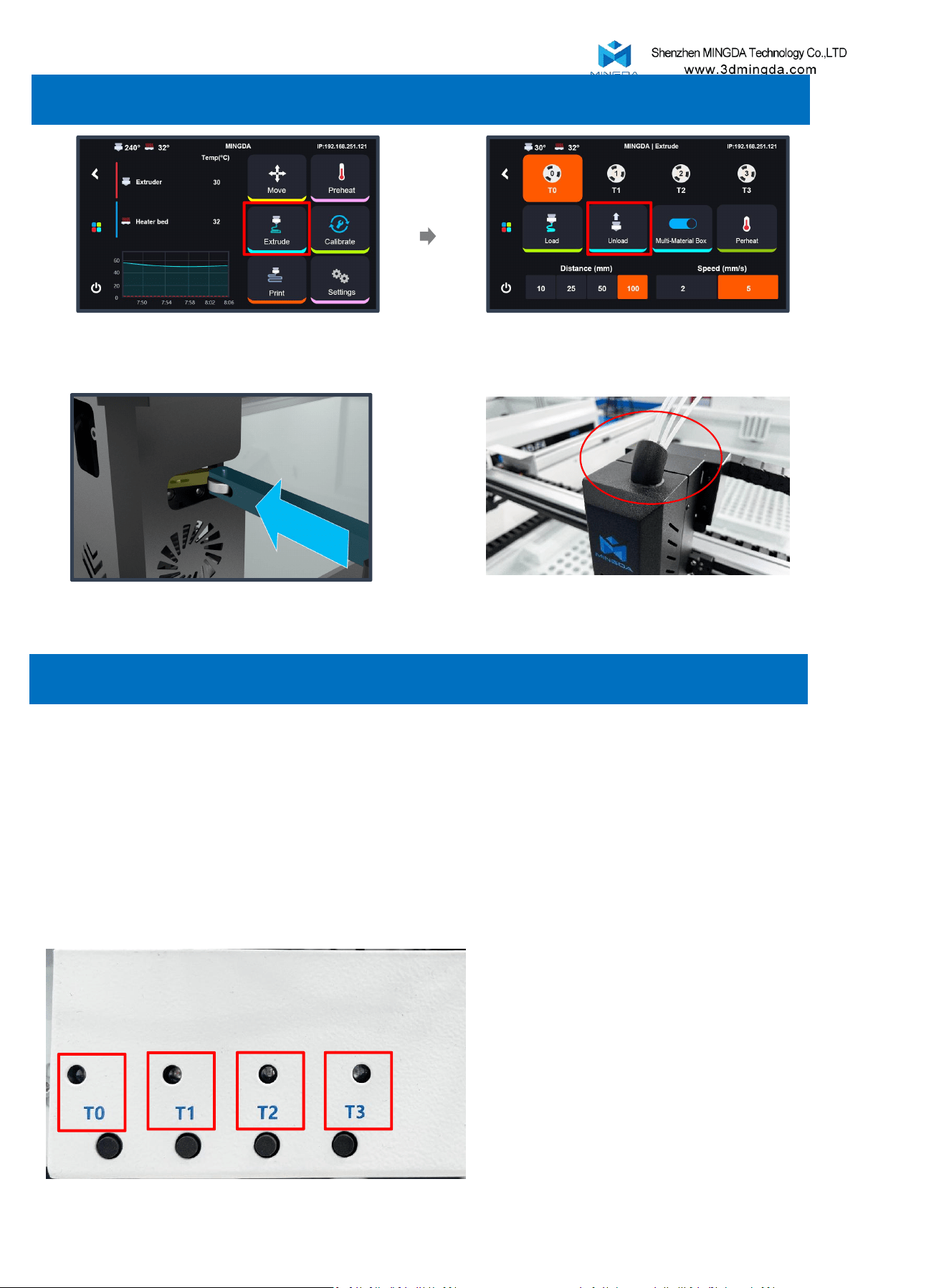
-A green indicator light means the corresponding channel has filament available.
-If the light is off, the channel is empty.
-A red indicator light signals a filament error. Check the on-screen message for details, or try
unloading and reloading the filament to resolve the issue.
Before unloading, ensure the printhead is not using the filament.
If it is, tap “Unload” on the screen first.
22
9. Unload the filament in the extruder
The filament will be cut automatically
Click “Extrude”
The filament is fully unloaded from the printhead 15 seconds
after the cutter finishes.
10. Unload the filament in the tube
Click “Unload”
11. Slicing Software Installation and Usage
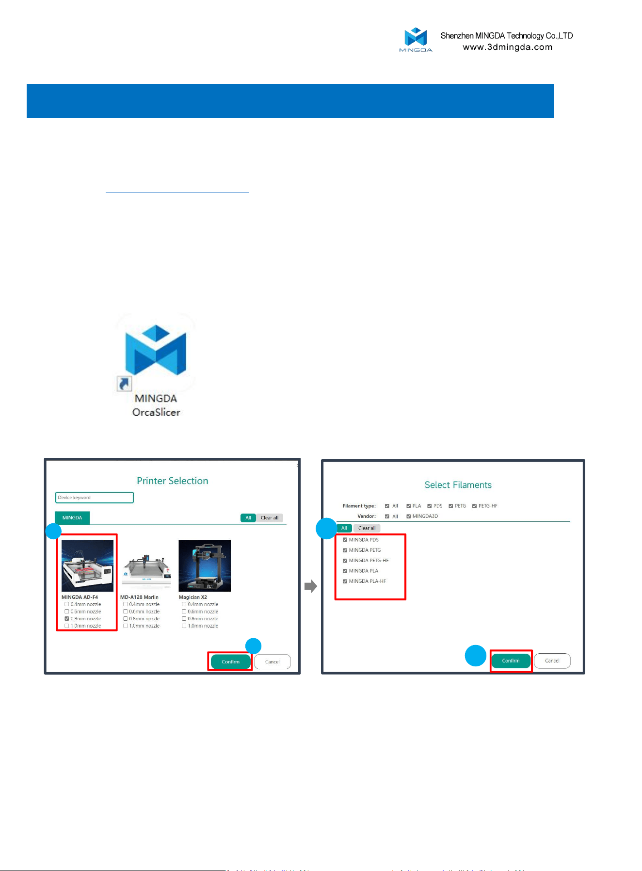
Installation:
Search "www.3dmingda.com/download" in any Broswer.
Download "MINGDA OrcaSlicer"
Configuration:
If you are the first time to use MingDa OrcaSlicer, you will
enter the configuration wizard.
Select the filament type.
1
2
2
Select MingDa AD-F4 0.8mm nozzle, Click ”Confirm”.
1
23
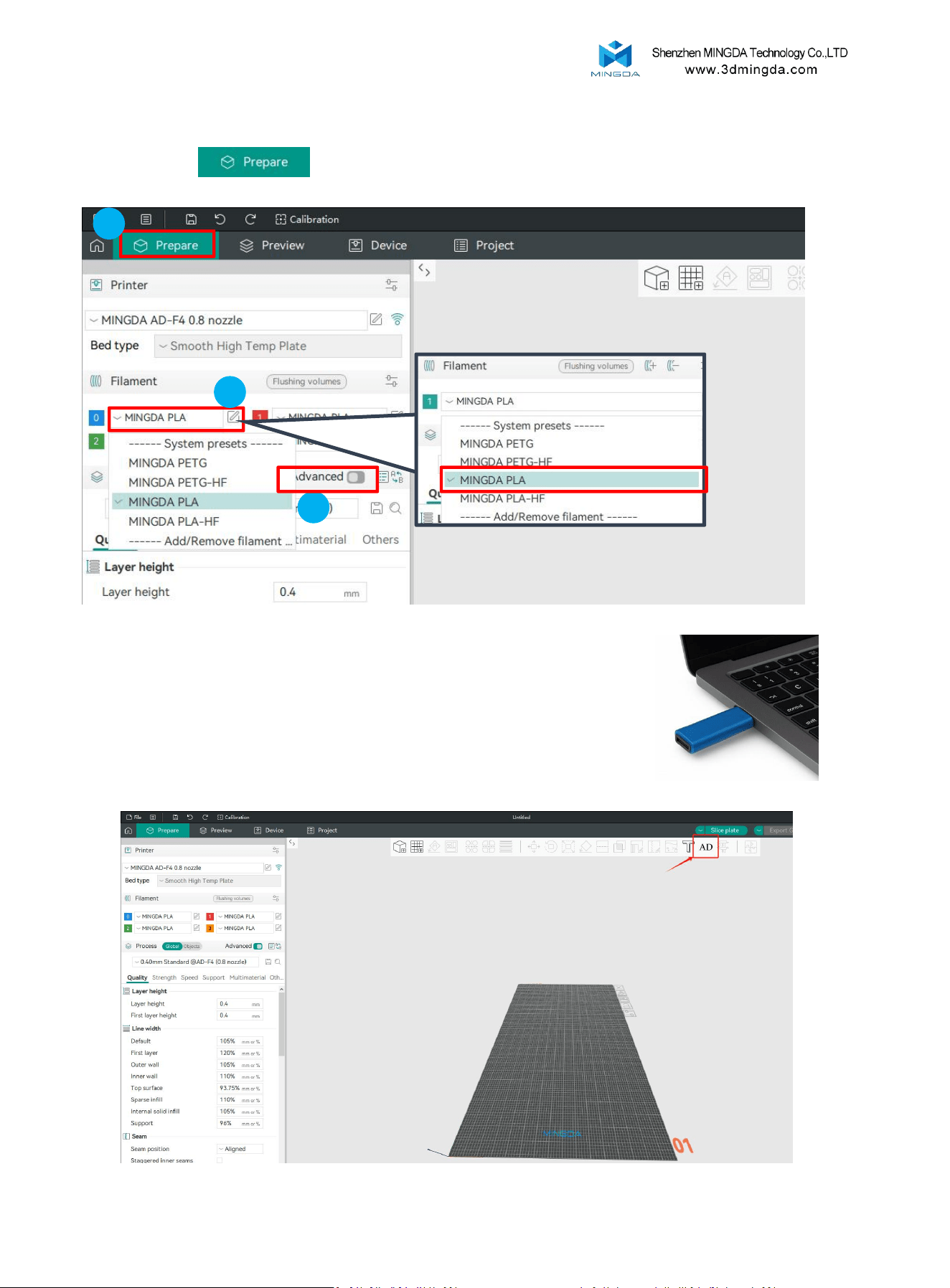
Select the filament you want to print;you can select Advanced Mode to unlock more setting parameters.
Slicing Software Installation and Usage
Click “Prepare”
1
2
3
Note: Before running the Adword slicer please insert the dongle on your computer
AdWordCraft
Click AD to run the Adword Craft slicer
24
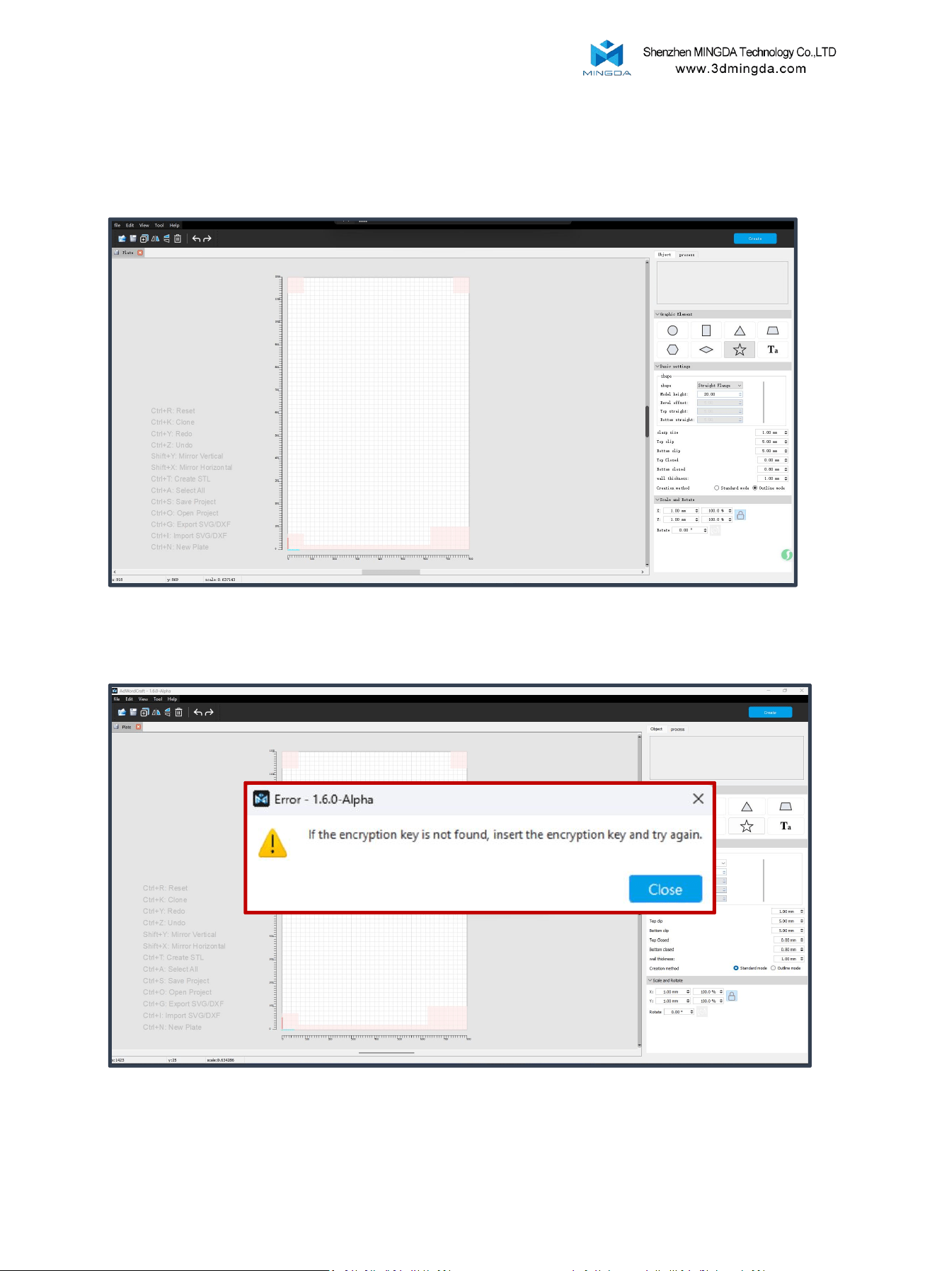
With the dongle connected, AdWordCraft will run normally.
If the dongle is removed during operation, the software will immediately stop functioning and display an error.
25
26
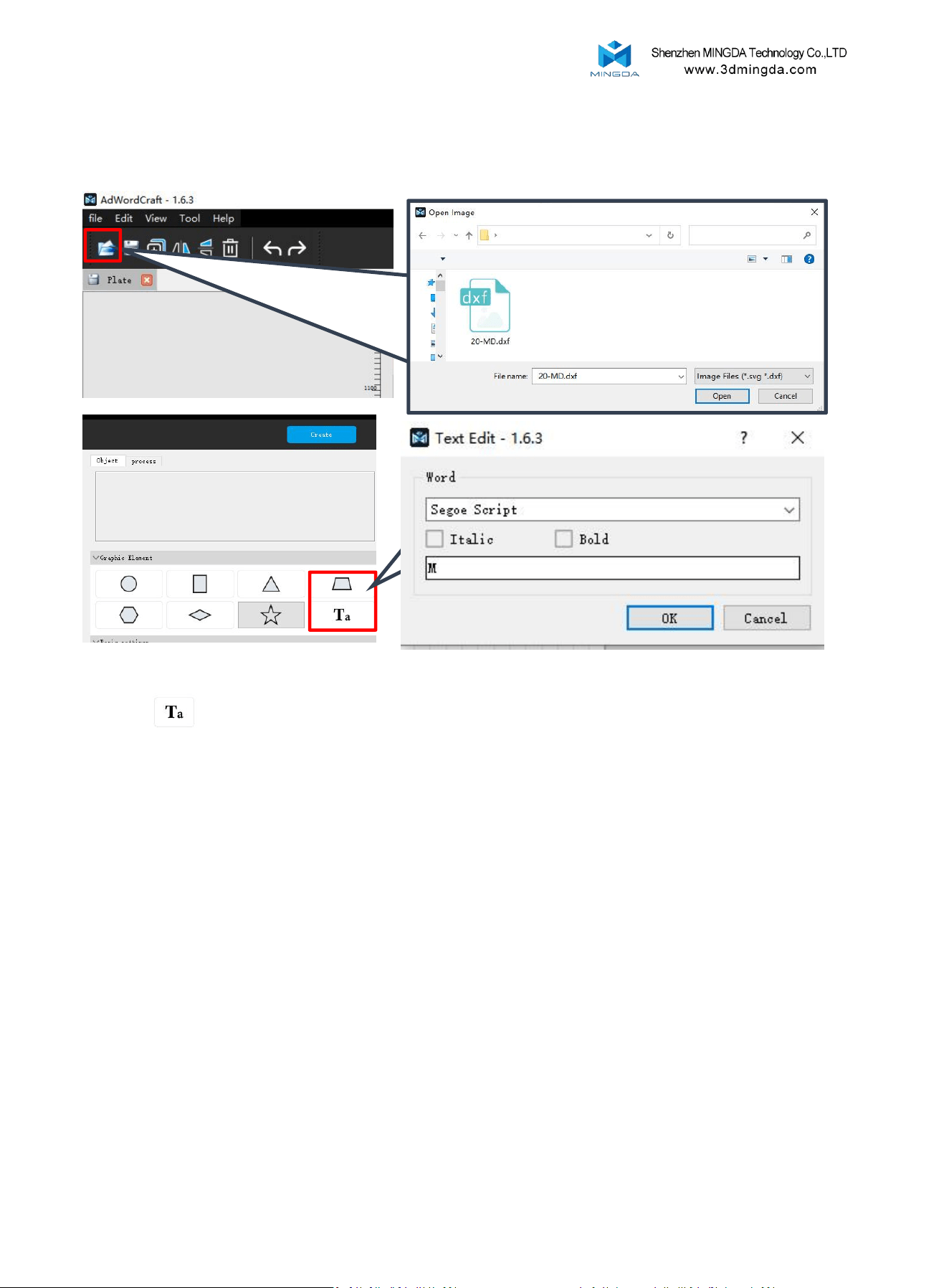
Create text for printing
You can import pre-designed vector files [.svg or .dxf] from the File menu or create designs directly using the
text tool , as shown in the example above.
2
1
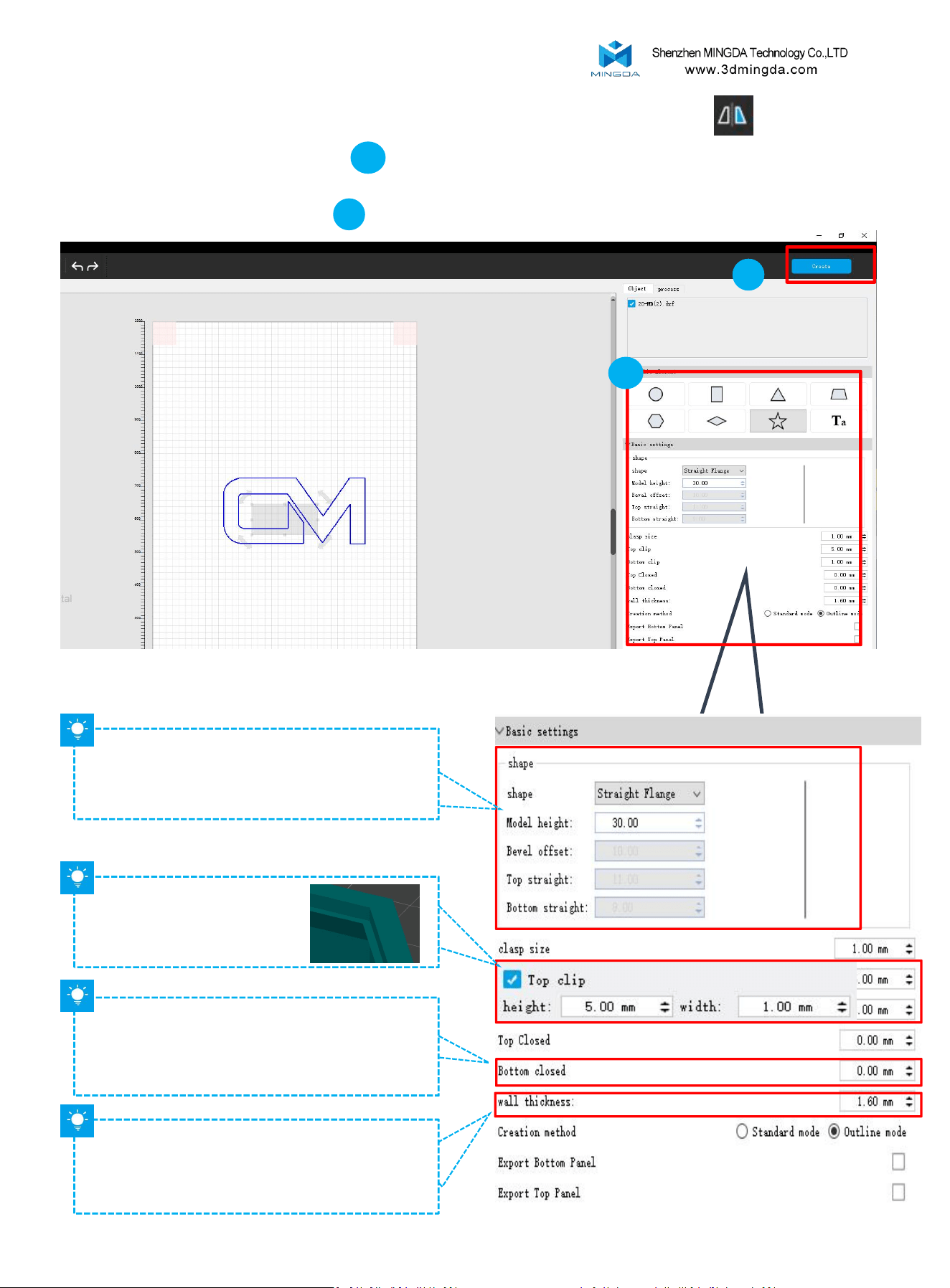
Model height; Setting of side shape and parameters;
[Select Straight Flange, Model height set to 40-60mm]
The bottom thickness of the model can be set to 2mm
if needed..
The wall thickness of the model is set as a multiple
of the nozzle size.
For example, with a 0.8mm nozzle, the wall
thickness can be set to 1.6mm.
Set the top card slot: used to
secure the backing plate of
advertising text.
27
2. You can adjust parameters in the right panel , including side border shape, height, bottom thickness, and wall
thickness.
3. After configuring the parameters, Create the file to your computer.
1. After creating or importing a vector file, select the model and choose the Horizontal Mirror option.
2
1

Click , upload your file in your slicer.
1
2
3
Import print file
Adjust your model parameter.
28
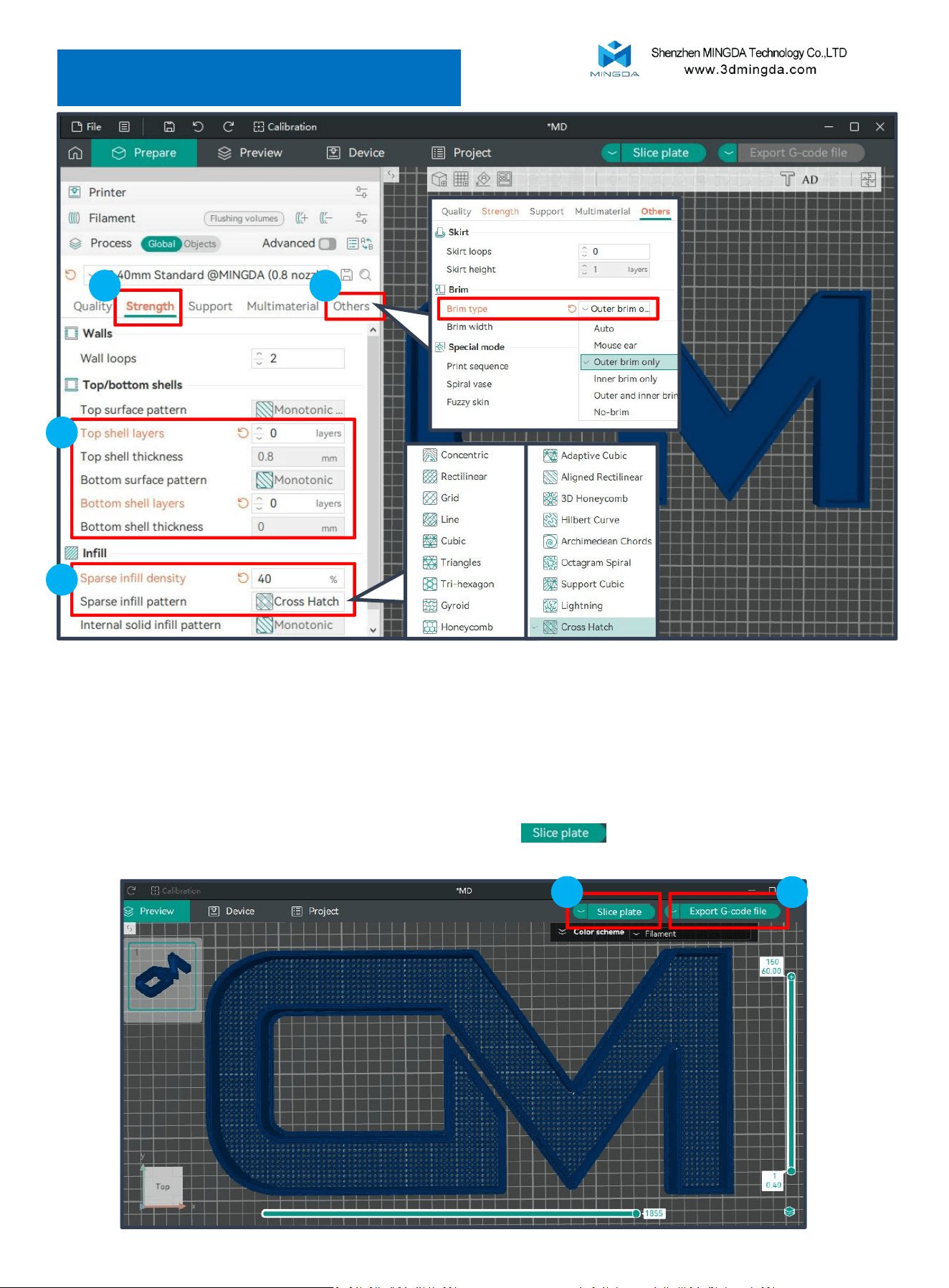
Bottom Pattern Settings
1
2
3
4
1. Click “Strength”;
2. Set Top Shell Layers and Bottom Shell Layers to 0 to prevent the top and bottom shells from affecting the bottom pattern.
3. In the Infill section, set the Sparse Infill Density to 40% (the density can be adjusted as needed). Choose the desired pattern
style for Sparse Infill Pattern.
4. Click “Others” and set the Brim Type option to Outer Brim Only. This generates only the outer edge of the model to enhance
its adhesion to the platform.
5. After completing the model parameter settings, click “Slice Plate” to preview the slicing.
6. “Export G-code file”
5
6
29
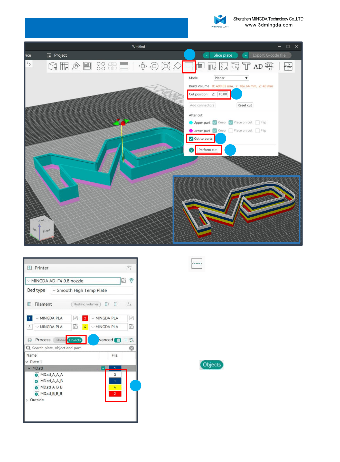
Side Multi-Color Settings
2
1. Click Cut [C]
3
4
1
2. Select the height of the cut position;
For example: for a 40mm-height model requiring four
colors, we may choose 10mm, 20mm, and 30mm heights
for sequential cutting.
6
5
3. Check "Cut to parts" to maintain original positioning
during model segmentation
4. Click on 'Perform cut'
5. Click on 'Objects' to switch interface views
6. In the interface, double-click color blocks to assign
different colors to each of the four models
30
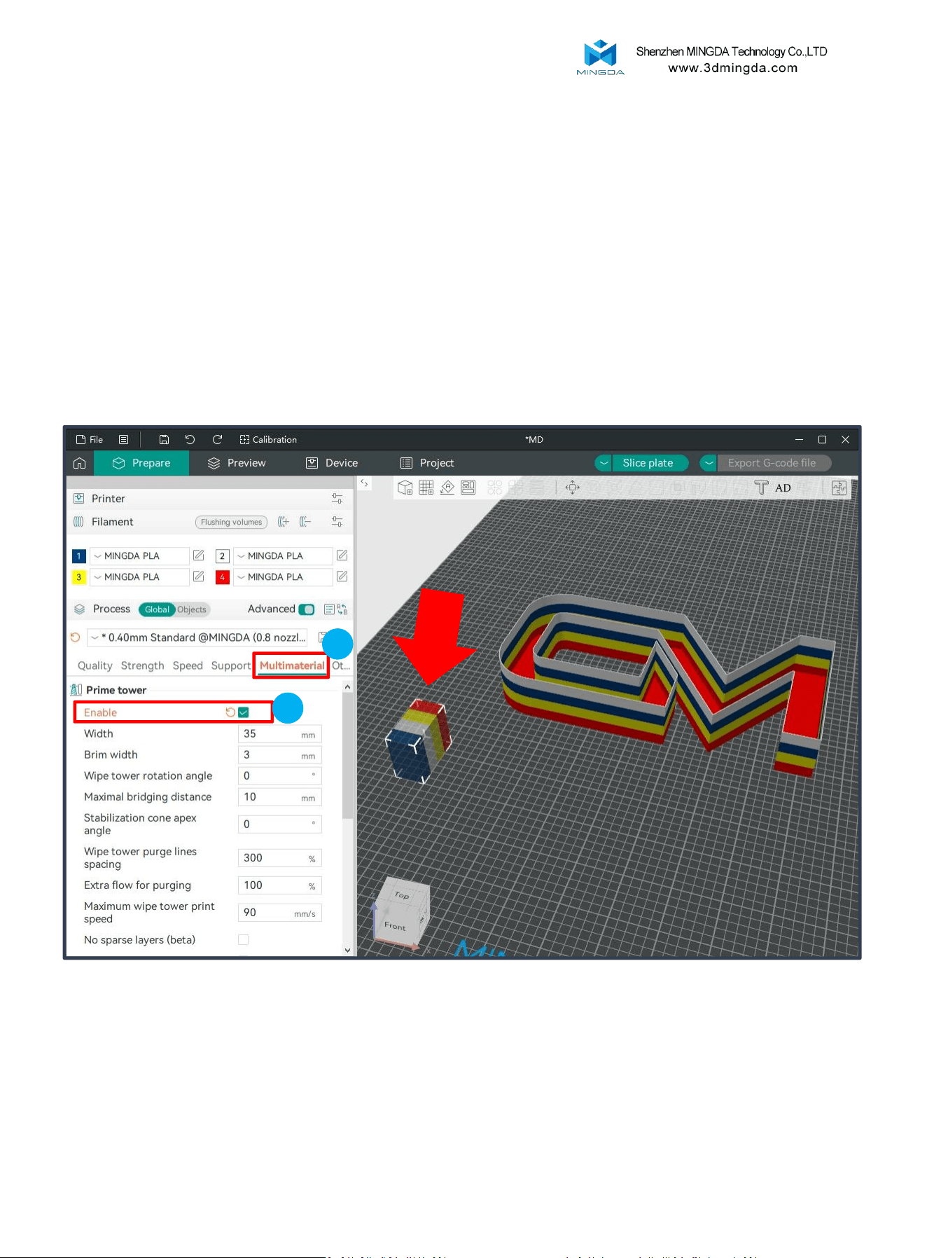
Cautions:
1. Avoid setting the wipe tower size too small, as insufficient purging may lead to
filament mixing.
2. Ensure the prime tower is positioned away from the model to prevent overlap.
Start the Prime tower
1
2
1. Select the "Multimaterial" section.
2. Check the "Enable" option in the "Prime tower" settings.
During the printing process of multi-color models, filament switching may leave residual filament from the previous
color in the nozzle, causing color mixing issues on the model.
Using a Prime Tower can resolve this problem. Before switching filaments during printing, the nozzle prints a Prime
Tower, where the residual filament is deposited. This effectively prevents color mixing during filament transitions.
31
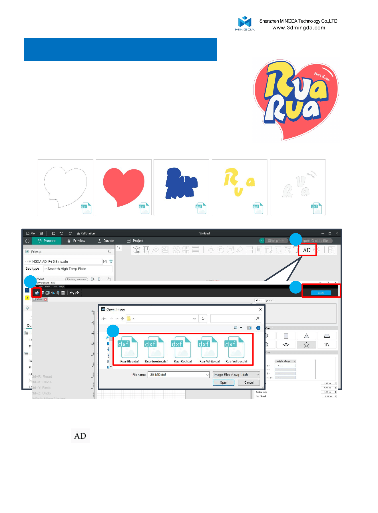
Bottom Multi-Color Settings
Using the example on the right (colors: red, yellow, white, blue):
When exporting the vector file, you can subdivide it into separate files.
For instance:
1. Export the model border as an individual dxf or svg file.
2. Export each of the four colors (red, yellow, white, blue) as separate dxf or svg files.
This approach ensures better management and precise application of each design
element during further processing or printing.
Click the AD icon , then import the created dxf or svg files individually into the AdWordCraft software. Set the
parameters as needed and save your settings.
1
2
3
4
32
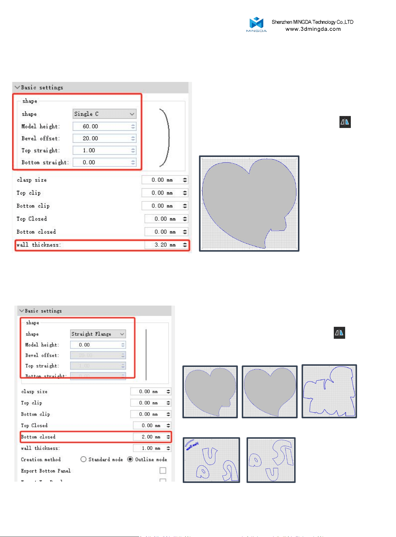
Model Border Parameter Settings
Model Bottom Parameter Settings
1. Select the desired side shape and adjust the corresponding
parameters.
2. Set “Bottom Closed” at 0.
3. Set the appropriate “Wall Thickness”.
4. Select the model and apply a “Horizontal Mirror”.
5. Click “Create” to save the file.
1. Set the bottom thickness to 2mm, and cancel or set all other
parameters to zero.
2. Select the model and apply a “Horizontal Mirror”.
3. Click “Create” to save the model.
Entire bottom Red heart
White font Yellow font
Blue side
Border
33
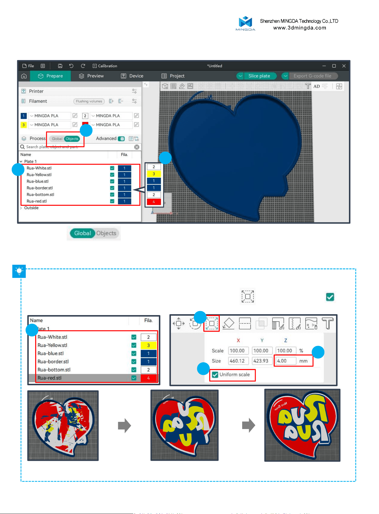
Import the created model files into Mingda OrcaSlicer.
Model File Adjustment
1. Click the button to switch to the “Objects” interface.
2. Double-click the color block to change the model to the desired color.
3. Adjust the positions of the models as needed, moving each to its correct location.
1
2
3
Since the models are stacked together, making it difficult to differentiate and adjust them, we can modify the height
of some models first to make it easier to adjust their positions.
1
Select the model from the left side; modify its Z-axis height by clicking Scale [S] . Uncheck Uniform Scale ,
then increase the Z height. After making the adjustments, you can now easily adjust the positions of each model.
2
3
4
After the adjustments are complete, you can modify the models back to their original height.
34
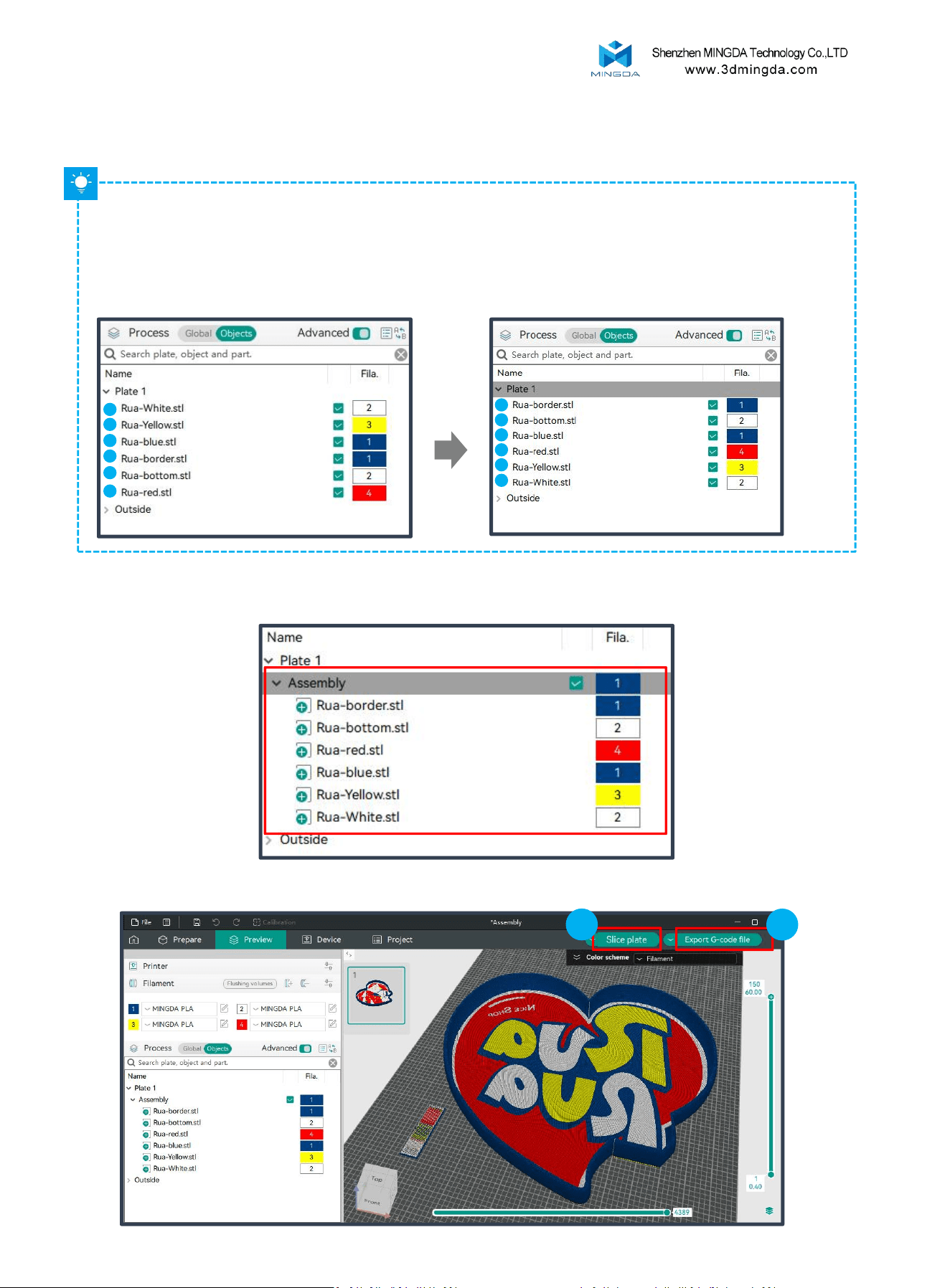
For models that overlap, the smaller model has higher priority.
In the “Objects” interface, the higher-priority models should be placed at the bottom, and the lower-priority
models at the top.
Based on the current model, the priority order is as follows:
White font > Yellow font > Blue side > Red heart > Entire bottom > Border.
6
5
4
3
2
1
1
2
4
6
5
3
4.We need to organize these models to ensure each color is printed correctly.
You can directly drag and drop the corresponding STL files in the left panel to arrange the models in the desired order.
5. After adjusting the order, press [Ctrl + A] to select all the model files. Right-click and choose “Assemble” to group all
the model files into a single Assembly.
6. Click "Slice Plate" to preview the model. If everything is correct, proceed by clicking "Export G-code File".
1
2
35
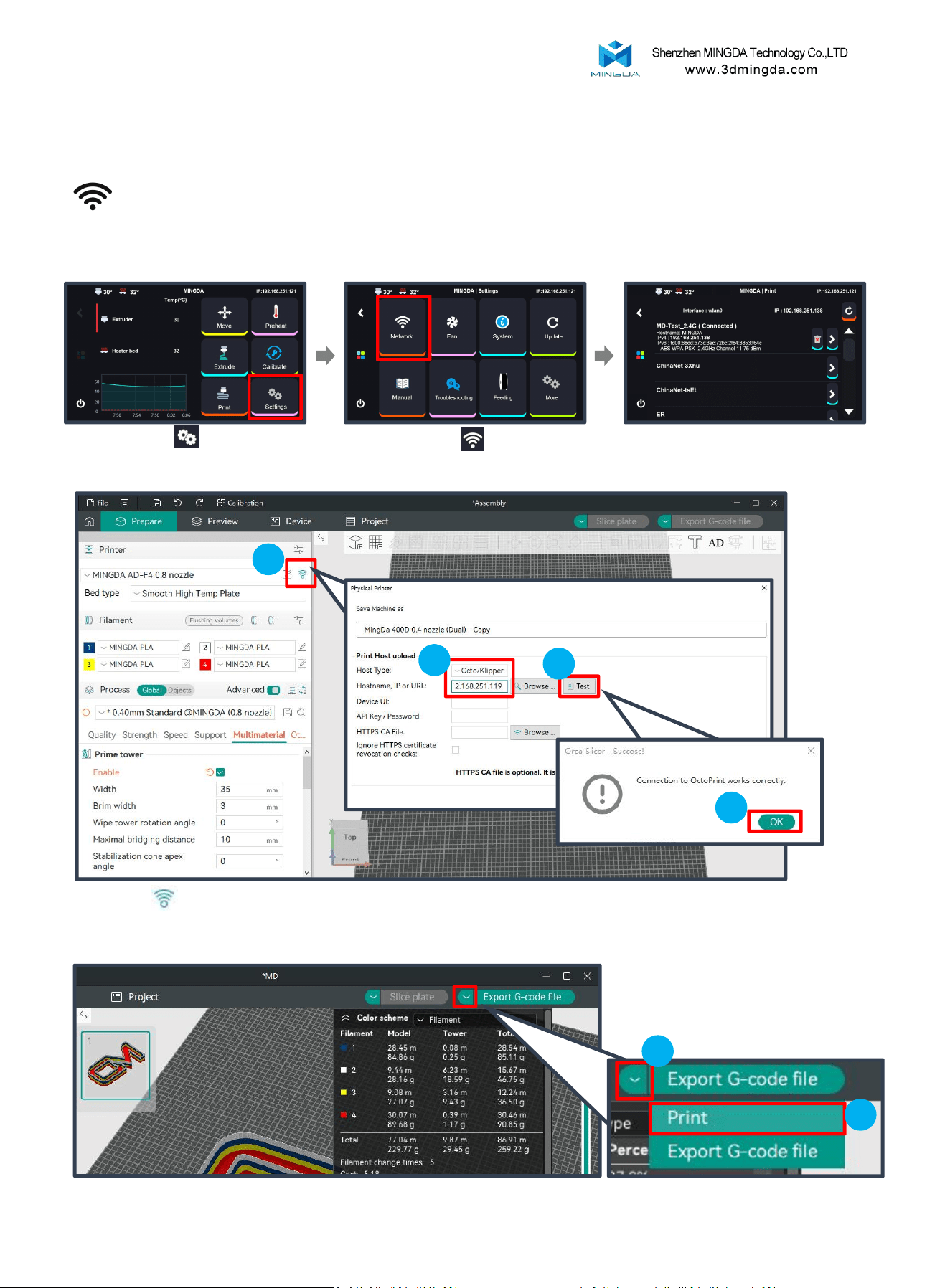
LAN Printing (Recommend)
Ensure that the printer and the computer host are on the same local network.
Click "Settings" to enter the
settings page.
Click "Network" to enter
the network page.
Check the printer's IP address.
Click WIFI , select Host type as Octo/Klipper, enter the printer’s IP address, and click “Test” and “OK”
1
2
3
4
Printing
File Transfer:
1
2
36
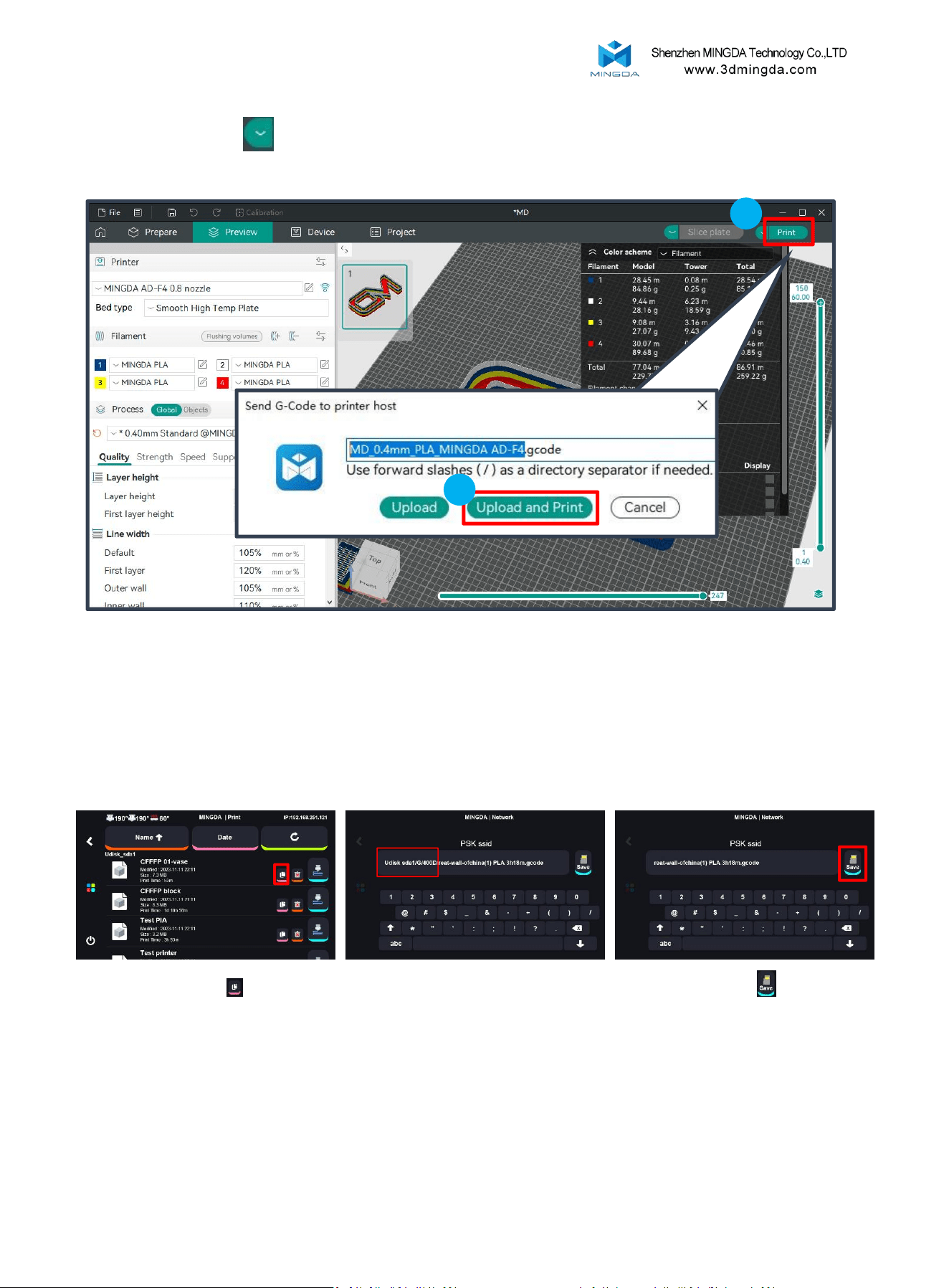
Click the dropdown icon in the top right corner , select "Print."
Click "Print" and choose "Upload and Print."
1
2
2
Copy gcode from USB to printer
Click “Copy”
Remove the text before and
including the "/" symbol.
Then click “Save”
37
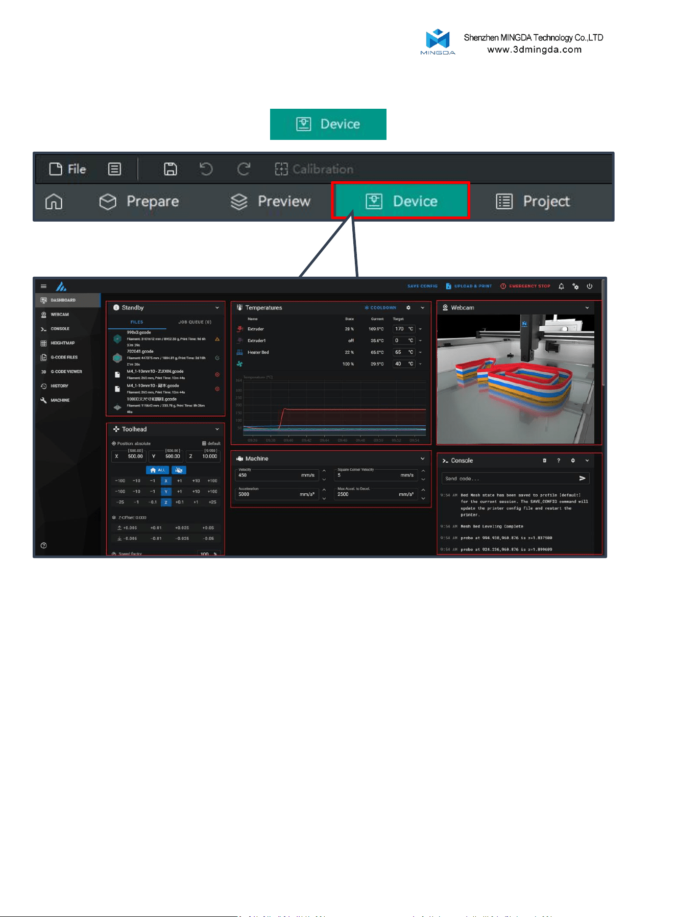
After successful connection, click on "Device"
Device Connection
1.Task List
4.Movement
Control
2.Temperature Control
5.Printer Limits 6.Console
Enter the control interface below the diagram
1. Task List: Drag G-code files to this task list for printing.
2. Temperature Control: Displays machine temperature changes and allows pre-setting
nozzle and bed temperatures.
3. Camera: Monitors the printing status.
4. Movement Control: Controls the movement of each axis and allows compensation
settings after leveling.
5. Printer Limits: Controls the maximum acceleration of the printer, usually doesn't need
to be changed.
6. Console: Sends G-code commands to run the machine and displays error output.
3.Camera
38

10. Maintenance and Care
Nozzle Cleaning: After printing, clean any remaining material from the nozzle using a lint-
free cloth. Take advantage of residual heat to clean the nozzle efficiently. Do not touch the
nozzle directly to avoid the risk of burns.
Filament Replacement: Replace filament as needed based on usage and material type.
Use MINGDA filament for best results. Store unused filament in a sealed container to avoid
moisture and brittleness.
Platform Inspection: Inspect the glass print platform for any signs of damage. If any
damage is found, contact your distributor to obtain a replacement.
Regular Lubrication: Lubricate the guide rails and bearings regularly. Friction between parts
during operation can cause wear and noise if not properly lubricated.
Feed Gear Cleaning:Clean the feed gear every three months to remove accumulated
residue. This helps maintain feeding accuracy and system stability.
Cutter Replacement: Perform quarterly inspections to check for visible blade wear or
damage. If the cutter produces uneven cuts, fails to sever the filament, or shows abnormal
resistance or noise during rotation that interferes with normal printing, it should be replaced
without delay.
39
Shenzhen MINGDA Technology Co., Ltd
Tel: 0086-13530306290
Email: suppo[email protected]om
www.3dmingda.com
Address: No. 19, Dahe Industrial Zone, Longhua District,
Shenzhen, 518110, Guangdong Province, China.