Eagle Foodservice Equipment, Eagle MHC, and SpecFAB
®
are divisions of Eagle Group. ©2022 by the Eagle Group
• 100 Industrial Boulevard, Clayton, Delaware 19938-8903 U.S.A.
• Phone: 302/653-3000 • 800/441-8440 • Fax: 302/653-2065
• www.eaglegrp.com • www.eaglegrpnews.com • www.eaglemhc.com
INSTALLATION INSTRUCTIONS
Electronic Hand Sink with AC Adapter
EG9961 Rev 10/22
CAUTION
INSPECT CONTENTS IMMEDIATELY AND FILE CLAIM WITH DELIVERING CARRIER FOR ANY
DAMAGE. SAVE YOUR BOX AND ALL PACKING MATERIALS. YOU ARE RESPONSIBLE FOR
DAMAGE TO YOUR UNIT IF RETURNED IMPROPERLY PACKED.
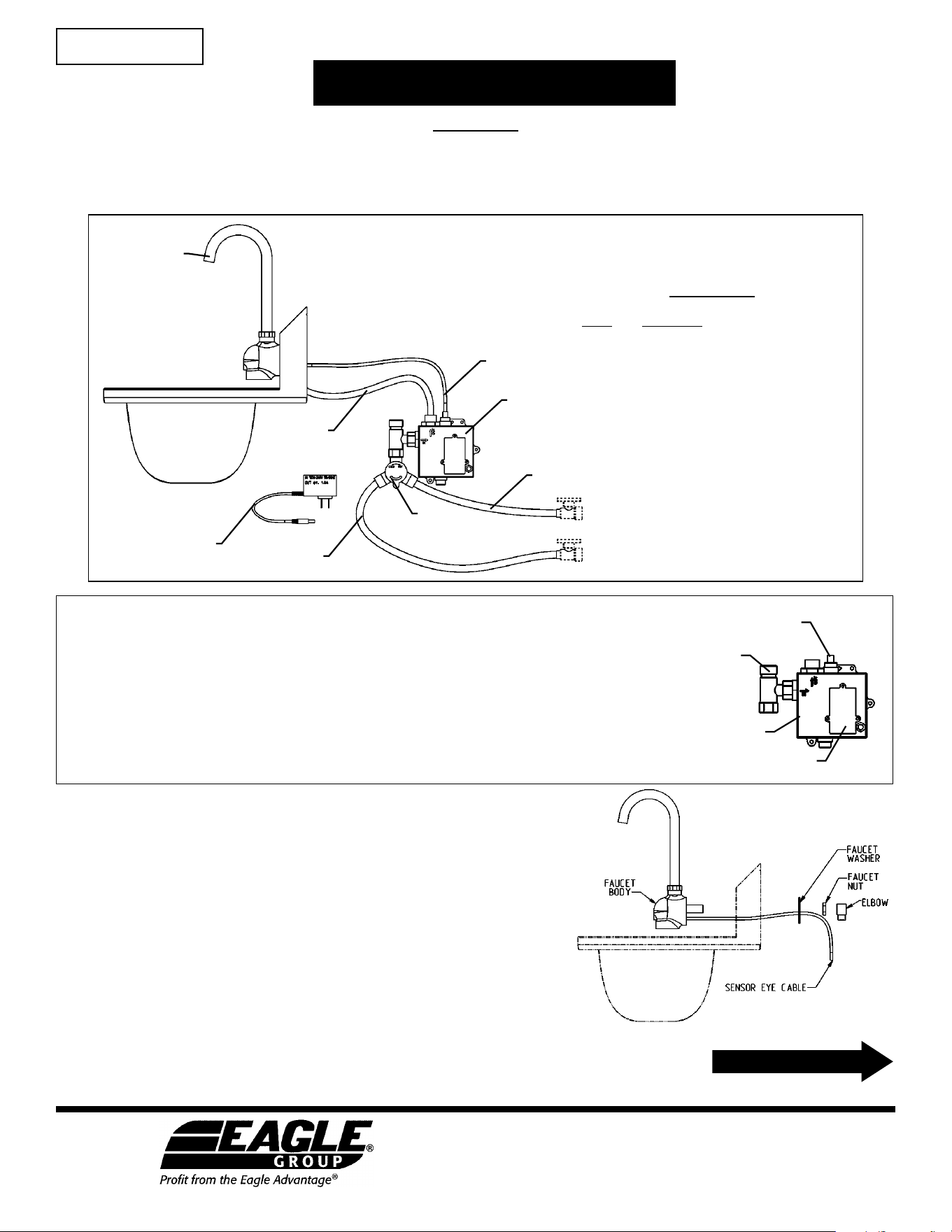
Parts List
item# description
INSTRUCTION SHEET
#312184
2
1
8
3
6
4
5
7
1 . . . . . . Electronic eye faucet
2 . . . . . . Faucet control box
3 . . . . . . Water Tempering (or “Mixing”) Valve
4 . . . . . . AC Adapter
5 . . . . . . Sensor Cable
6 . . . . . . S/S Hose with blue stripe
7 . . . . . . S/S Hose with red stripe
8 . . . . . . S/S Hose (mixed)
Step 1 - Mount faucet body onto sink.
(Refer to fig. 1)
a. Carefully thread sensor cable through hole in backsplash.
b. Affix faucet onto backsplash, using plumbers’ putty (not included)
between backsplash and faucet body.
c. Install faucet washer, being careful to not pinch the sensor cable.
d. Install faucet nut and tighten while ensuring faucet body is level.
Wipe away excess plumber’s putty.
Before assembly…
1. Flush all water lines until water runs clear before connecting faucet to supply stops.
2. Avoid surroundings with bright lights, highly reflective surfaces, and sunlight which can
affect the sensor’s performance.
3. Make sure the tee-shaped fitting with the filter is installed onto the control box
(see illustration at right).
4. Remove and discard the protective cap over the sensor connection on top of the control
box. Only remove lower cap if using the AC adapter.
fitting
with filter
sensor connection
HOT
COLD
control box
battery compartment
fig. 1
(continued on Page 2)
Step 5 - Check for leaks.
IF THERE IS A LEAK, UNPLUG POWER ADAPTER FROM THE WALL
BEFORE
TENDING TO LEAK.
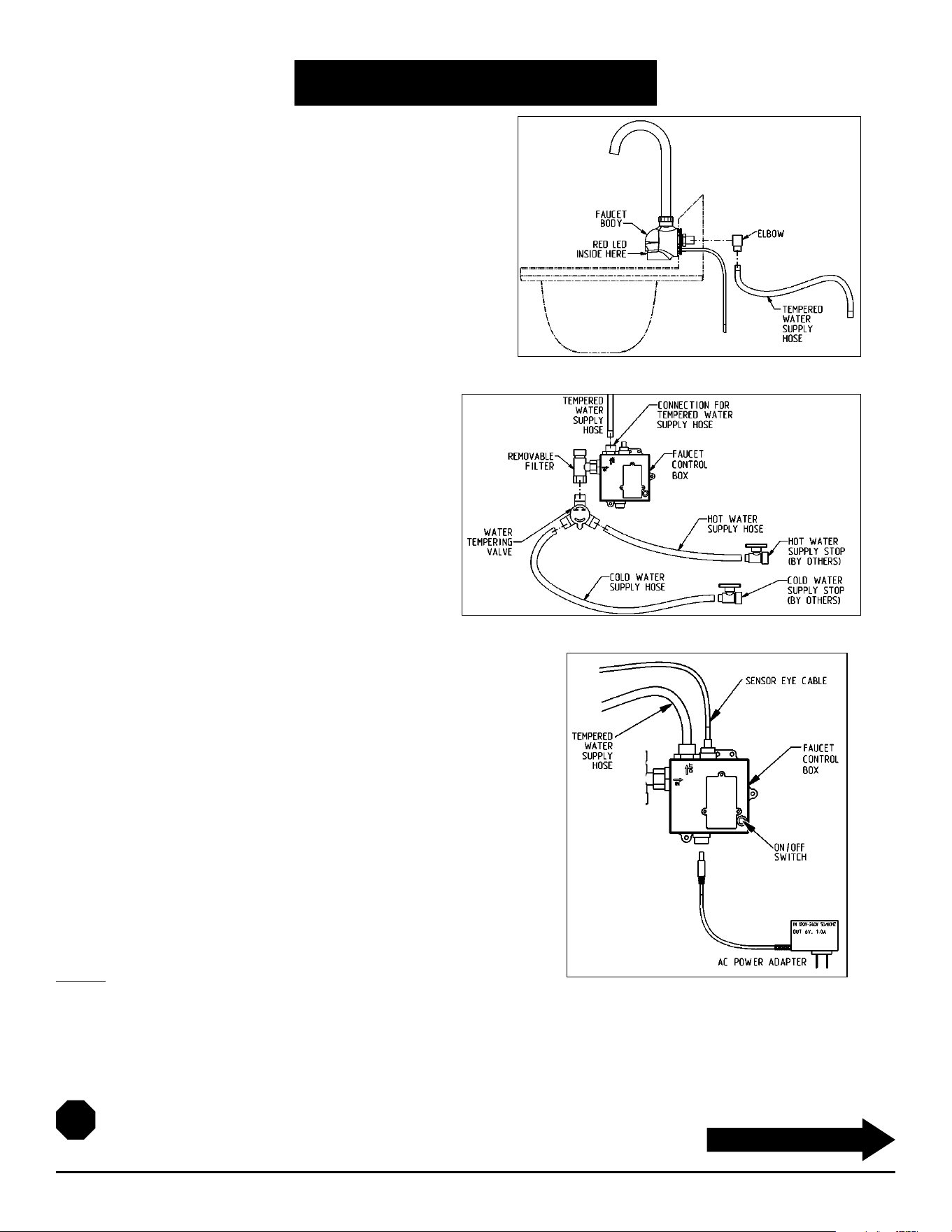
Step 2 - Connect elbow and supply hose.
(Refer to fig. 2)
a. Wrap Teflon tape (not included) around threaded stem of
faucet body, and attach NPSM 90-degree plumbing elbow onto
threaded stem.
b. Attach 30" hose from elbow to fitting on top of control box.
Step 3 - Connect water supply.
(Refer to fig. 3)
a. Attach water tempering valve to bottom of tee at
faucet control box assembly.
b. Attach water supply hose (from back of faucet) to
top of control box.
c. Connect supply hoses (hot = hose with red stripe,
cold = hose with blue stripe) from the plumbing
stops to the water tempering valve.
d. Mount faucet control box to wall (hardware not
included) near sink.
Step 4 - Connect wiring to control box. Plug in power supply.
(Refer to fig. 4)
a. Plug sensor eye cable into connector on top of control box.
b. Plug power adapter into connector on bottom of control box.
c. Plug power adapter into 120V electrical power supply outlet. If wire
between faucet and power adapter is too long, coil the excess wire
and secure it so that it does not contact any surface or object below it.
Installation is complete.
INSTALLATION INSTRUCTIONS
Electronic Hand Sink with AC Adapter
2
(continued on Page 3)
(End)
fig. 2
fig. 3
fig. 4

OPERATING INSTRUCTIONS
Electronic Hand Sink with AC Adapter
OPERATION
1. Place hands under spout. Water will flow as long as the user’s hands remain within sensor range.
2. Clean filter every month.
3. Keep electronic eye cover clean.
4. Red flashing in the electronic eye indicates low batteries. Replace with four (4) “AA” alkaline batteries. Fresh batteries should
last 400,000 on/off cycles.
5. Solid red light and no water flow indicates batteries are dead.
6. When used with the optional AC adapter, the faucet will automatically switch to AC power and conserve its battery power.
SENSOR RANGE SETUP
The sensor range is preset at the factory during assembly but can be further adjusted using the steps below.
1. The sensor range is adjustable from 3/4˝ (19mm) to 6-11/16˝ (169.9mm). if there is a disruption of power, the sensor range is
saved and will revert to the last saved setting when restored.
2. Faucet sensor range is set by using the On/Off button on the front of the control module. Do not attempt to open the control
module box.
3. Push and hold the On/Off button; water will flow. Alter holding the button 5 to 7 seconds, the water flow will stop and the red
LED in the sensor lens (on the front of the faucet body) will turn on solid.
4. Release the On/Off button. The red LED will turn off signaling that the sensor is ready for set-up for the next 15 seconds.
5. Hold your hand still in front of the sensor at the desired sensor distance. The red LED will flash roughly 5 times then remain on
for 2 seconds indicating the new range has been set.
6. If step 5 is not done within 15 seconds, the red LED will blink quickly then stop indicating the sensor range has NOT been
changed. Start over at step 3 to change the sensor range.
BATTERY REPLACEMENT
1. Your sensor faucet requires four (4) AA alkaline batteries. If AC adapter is used, unplug it from its power source.
2. Remove the battery cover's three (3) screws and pull cover away from the control box.
3. Remove the old batteries.
4. Install the new AA batteries, making sure that the + and - ends are facing the correct direction. Return the battery cover to its
spot and tighten screws. If the AC adapter is to be used, plug it in at this time.
5. With the disconnection of power, the sensor range is saved and will revert to the last setting when power is restored.
SPECIFICATIONS
Max running time: 30-seconds while hands are in sensor range or On/Off button pressed
Response time: 0.3-seconds
Sensing range: 3/4˝ (19mm) to 6-11/16˝ (169.9mm)
Power source: AC/DC
Low battery indicator: Flashing red LED
3
(continued on back page)

Eagle Foodservice Equipment, Eagle MHC, and SpecFAB
®
are divisions of Eagle Group. ©2022 by the Eagle Group
• 100 Industrial Boulevard, Clayton, Delaware 19938-8903 U.S.A.
• Phone: 302/653-3000 • 800/441-8440 • Fax: 302/653-2065
• www.eaglegrp.com • www.eaglegrpnews.com • www.eaglemhc.com
FAQ
Electronic Hand Sink with AC Adapter
FREQUENTLY ASKED QUESTIONS
Q. Can I operate the faucet manually, without using the electronic eye?
A. Yes. Press the ON/OFF button and water will start flowing. To turn water off, press ON/OFF button again.
If you forget to turn the water off, the faucet will automatically turn it off after 30 seconds.
Q. What is the optimal sensing distance?
A. Just in front of the water stream on the side towards the user.
Q. Does the electronic eye require special maintenance?
A. For the sensor to function, the electronic eye must be clean. Use only mild soap and water. Wipe with a
soft cloth.
Q. How often should I clean the filter?
A. Depending on the quality of the water in your area, every 4 to 12 weeks.
Q. Why doesn't the water shut itself off after I have moved my hands away from the electronic eye?
A. Sensor range could be too long. User may have to adjust sensor range.
Q. No water comes out of the faucet and the red LED stays on. What is the problem?
A. Replace the batteries.
(End)