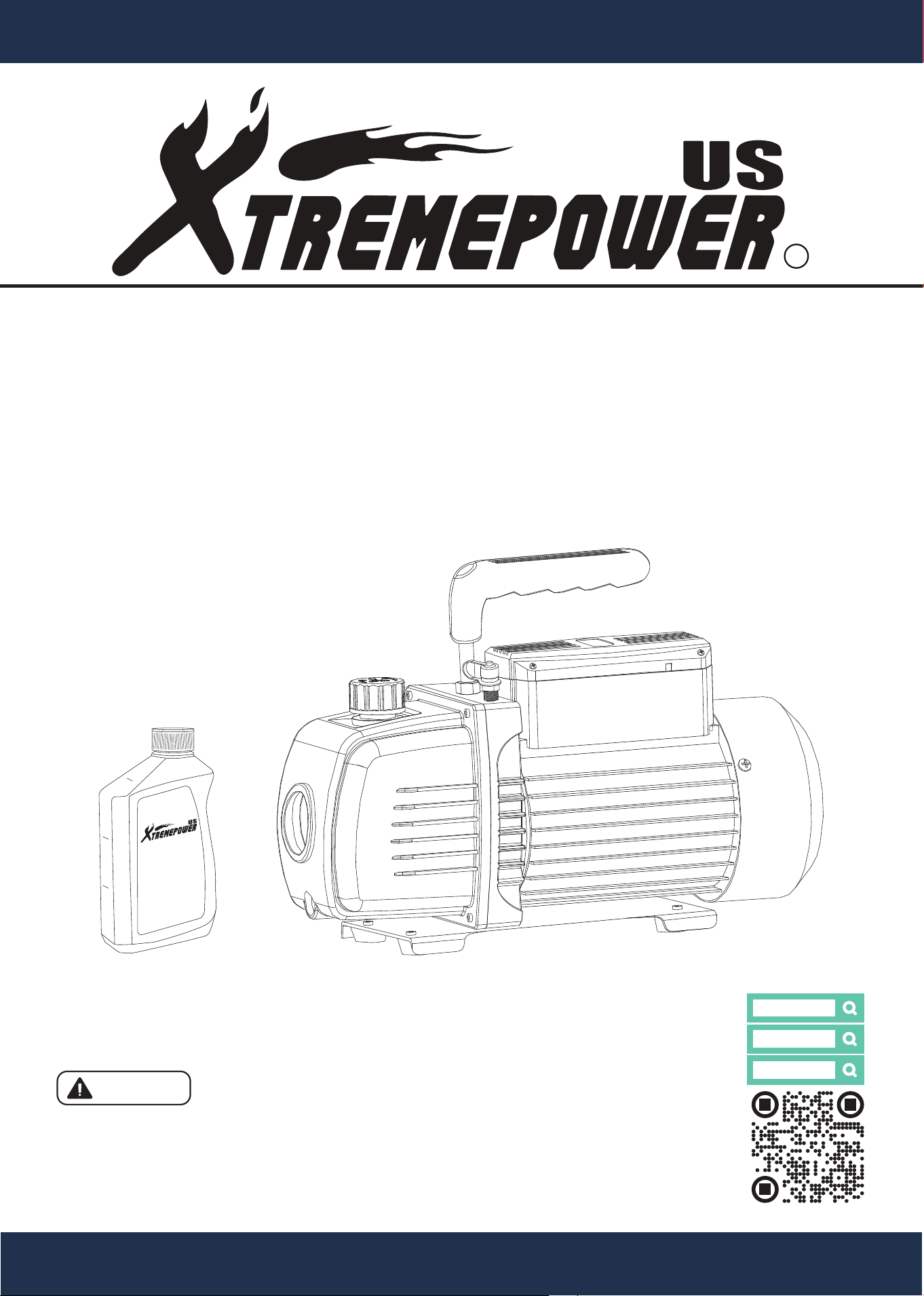
3.5CFM 1/4HP REFRIGERANT VACUUM PUMP
4.5CFM 1/3HP REFRIGERANT VACUUM PUMP
SKU: 71093 / 71095 / 71096
INSTALLATION AND USER’S GUIDE
Read all safety warnings and instructions.
Failure to follow the warnings and instructions may result in electric shock,
fire and/or serious injury.
Save all warnings and instructions for future reference.
DANGER
71096
VACUUM
PUMP OIL
Designed for Rotary
Vacuum Pumps
200ml
100ml
250ml
71095
71093

THIS PAGE INTENTIONALLY LEFT BLANK

CUSTOMER SERVICE
If you have any questions about ordering our pumps and replacement parts or other products, please feel free
to contact us using the following contact information:
Customer Service and Technical Support
Phone: (909) 628-0880
Email: [email protected]
Hours of Operation: Monday – Friday, 9AM – 4PM (CST)
TABLE OF CONTENTS
CUSTOMER SERVICE
Customer Service and Technical Support
IMPORTANT SAFETY INSTRUCTIONS
Legends and Symbols
GENERAL SAFETY
OVERVIEW (PRODUCT INFORMATION)
PACKAGE CONTENTS
REPLACEMENT PARTS
DISCLAIMER
Parts Diagram
INSPECTIONS
CLEANING PROCEDURES
1
1
1
2
2
3-4
5
5
5
6
6
7
7
8
8
8
8
8
9
10
10
11
TABLE OF CONTENTS
OPERATION
VACUUM PUMP OPERATING INSTRUCTIONS
FEATURES
MAINTENANCE
SAFETY WARNINGS AND MAINTENANCE INSTRUCTIONS
STORAGE GUIDELINES
1
COMPONENTS AND FUNCTIONS
SPECIFICATIONS
TROUBLESHOOTING
ATTENTION INSTALLER: This manual contains vital information regarding the installation, operation, and safe
use of this pump. It is essential to provide this manual to the end user of the product. Failure to read and follow
all instructions could lead to severe injuries.
USE OF NON-XTREMEPOWERUS REPLACEMENT PARTS VOIDS WARRANTY
DANGER: Ignoring these hazards can result in death, severe personal injury, or significant
property damage.
WARNING: Indicates potential hazards that can result in severe personal injury, death, or
significant property damage. Ignoring these warnings presents a real danger.
CAUTION: Indicates potential hazards that can result in minor or moderate personal injury,
property damage, or actions that are unpredictable and unsafe. Ignoring these cautions
presents a potential hazard.
NOTICE: This label indicates important special instructions that are not directly related to
hazards.
This guide provides instructions for installing and using the vacuum pump. If you have any questions about the
equipment, please contact XtremepowerUS.
This guide contains important information about safely installing and operating this product. After installation,
make sure to share this information with the owner/operator or leave it with them for their reference.
Legends and Symbols
When you come across the safety-alert symbol on your equipment or in this manual, pay attention to the
following signal words and remain vigilant about the potential for personal injury.
IMPORTANT SAFETY INSTRUCTIONS
WARNING
CAUTION
NOTE
Failure to comply with all instructions and warnings may lead to severe bodily injury or even
death. For optimal safety and functionality, it is advisable to have the product installed and serviced by a certified
service professional. Prior to using this product, installers, operators, and owners must carefully review these
warnings and all instructions provided in the owner’s manual. It is essential to leave these warnings and the
owner’s manual with the owner for their reference and safety.
CAUTION
To minimize the risk of injury, do not allow children to use on this product. Always supervise
children closely. CALIFORNIA PROPOSITION 65 - This product contains chemicals known to the state of
California to cause cancer and birth defects or other reproductive harm.
CAUTION
This vacuum pump is designed exclusively for use by technically trained refrigeration and air
conditioning service technicians. Due to the extremely high pressure and hazardous gases present in all
systems, misapplication could result in serious injury or death.
The manufacturer strongly warns against the sale or use of this product by anyone other than professionally
trained personnel.
WARNING
2
IMPORTANT SAFETY INSTRUCTIONS
DANGER

TO PREVENT EXPLOSION AND DEATH
• Air conditioning system service must be performed only by trained and experienced technicians to avoid
overfilling. Technicians opening the refrigeration circuit in automotive air conditioning systems MUST be
certified in refrigerant recovery and recycling procedures, in compliance with Section 609 of the Clean Air Act
Amendments of 1990. For additional information regarding ozone depletion and air conditioning service
regulations, visit the EPA’s website: www.epa.gov/ozone.
• Do not operate power tools in explosive atmospheres, such as in the presence of flammable liquids, gases,
or dust. Power tools create sparks that may ignite dust or fumes.
• Never use this vacuum pump to vent refrigerants into the air. Venting refrigerants into the air is illegal and
harmful to the environment.
WARNING
IMPORTANT SAFETY NOTICE
• The warnings and safety instructions in this manual are not intended to cover all possible conditions and
situations that may arise. Use common sense, caution, and care when operating or cleaning tools and
equipment.
• Always contact your dealer, distributor, service agent, or manufacturer regarding any problems or conditions
you do not understand before operating the product.
WARNING
3
IMPORTANT SAFETY INSTRUCTIONS
TO PREVENT ELECTRIC SHOCK AND DEATH
• Power tool plugs must match the outlet. Never modify the plug in any way. Do not use adapter plugs with
grounded power tools. Unmodified plugs and matching outlets reduce the risk of electric shock.
• Do not expose power tools to rain or wet conditions. Water entering a power tool increases the risk of electric
shock.
• Do not abuse the cord. Never use the cord for carrying, pulling, or unplugging the power tool. Keep cords
away from heat, oil, sharp edges, or moving parts. Damaged or entangled cords increase the risk of electric
shock.
• When operating a power tool outdoors, use an extension cord suitable for outdoor use. Using a cord
designed for outdoor use reduces the risk of electric shock. If operating a power tool in a damp location is
unavoidable, use a Ground Fault Circuit Interrupter (GFCI) protected supply. Use of a GFCI reduces the risk
of electric shock.
• The temperature of the pumped gas should not exceed 80°C (176°F), and the ambient environment
temperature should be approximately 5°C to 60°C (41°F to 140°F).
WARNING
POWER TOOL USE AND CARE
• Use the correct power tool for your application. The correct power tool will perform the job better and more
safely when used at the rate for which it was designed.
• Do not use the power tool if the switch does not turn it on and off. Any power tool that cannot be controlled
with the switch is dangerous and must be repaired.
• Disconnect the plug from the power source before making any adjustments, changing accessories, or
storing power tools. Taking preventive safety measures reduces the risk of accidentally starting the power
tool.
• Store idle power tools out of the reach of children, and do not allow persons unfamiliar with the power tool
or these instructions to operate it. Power tools are dangerous in the hands of untrained users.
• Maintain power tools. Regularly check for misalignment or binding of moving parts, breakage of parts, or
any other condition that may affect the power tool’s operation. If the power tool is damaged, have it repaired
before use. Many accidents are caused by poorly maintained power tools.
• Use the power tool and accessories as instructed. Always use the power tool, accessories, and tool bits in
accordance with these instructions. Take into account the working conditions and the specific tasks to be
performed. Using the power tool for purposes other than those intended may result in a hazardous
situation.
WARNING
WARNING
• Wear Safety Equipment: Always wear ANSI-approved safety goggles and heavy-duty work gloves during
setup. Wear goggles when working with refrigerants. Contact with refrigerants may cause serious injury.
Wear gloves when working with refrigerants to prevent chemical burns or other injuries.
• Prevent Leaks or Explosions: Incorrect use or connections may cause leaks or explosions. Read and
follow the instructions carefully and take all precautions to avoid leaks or explosions. Confirm that all
associated devices are properly grounded before use.
• Prevent Overheating: Do not cover the unit. The vacuum pump becomes very hot during use. Keep the
pump away from combustibles. Allow it to cool down completely before moving or storing.
• Do Not Leave the Tool Unattended: Always turn off the tool and unplug it from the electrical outlet when
leaving it unattended.
• Operate Only in a Well-Ventilated Area: Ensure sufficient airflow to avoid the accumulation of refrigerant
gases, which can displace oxygen and pose serious health risks.
• Avoid Moving Engine Parts: Keep the vacuum pump, gauge and hoses securely positioned away from any
moving engine components to prevent damage and injury.
• Turn Off Engine and A/C System Before Setup: Always turn off the vehicle's engine and air conditioning
system before attaching the gauge to ensure safe handling.
• Avoid Overfilling: Do not service air conditioning systems improperly. Overfilling can cause equipment
damage and pose safety hazards.
• For Professional Use Only: This vacuum pump is designed exclusively for use by technically trained
refrigeration and air conditioning service technicians. Due to the unusually high pressure and presence of
hazardous gases in all systems, misapplication could result in serious injury or death. The manufacturer
strictly warns against the sale of or use of this product by anyone other than professionally trained
personnel.
• California Proposition 65 Warning: This product contains chemicals known to the State of California to
cause cancer, birth defects, or other reproductive harm.
• Certified Technician Requirement: The procedure outlined is to be performed only by technicians certified
in refrigerant recovery and recycling procedures, as detailed in compliance with the Clean Air Act
Amendments of 1990.
SAVE THESE INSTRUCTIONS FOR FUTURE REFERENCE
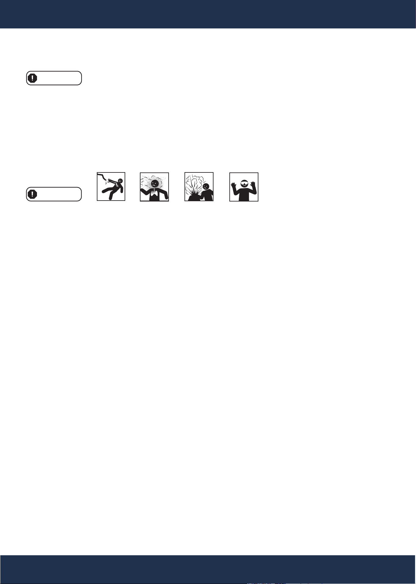
Read all safety warnings and instructions.
Failure to follow the warnings and instructions may result in serious injury.
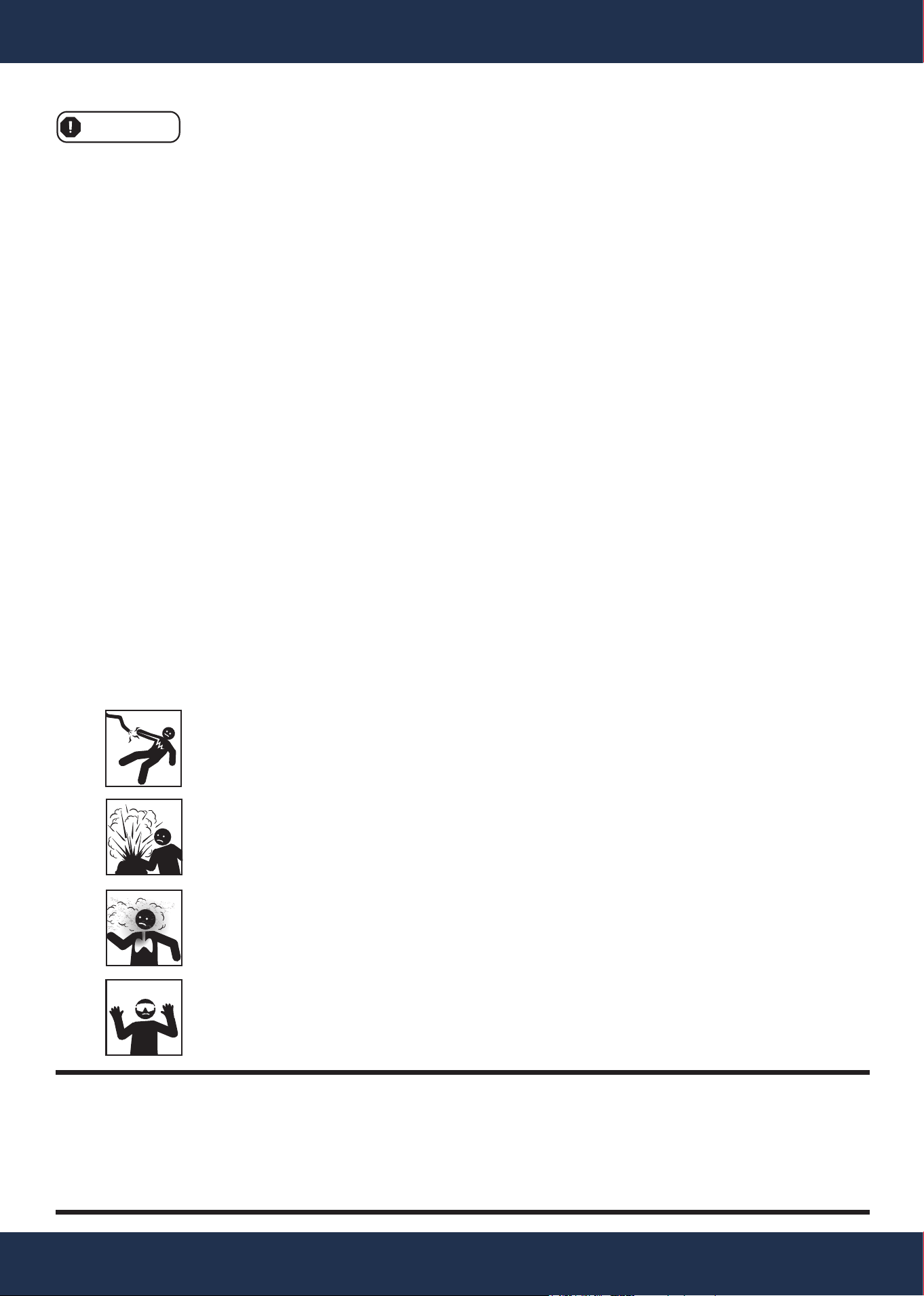
INHALATION HAZARD
HIGH PRESSURE HAZARD
PERSONAL PROTECTIVE EQUIPMENT REQUIRED
4
IMPORTANT SAFETY INSTRUCTIONS
4
PPE
TO PREVENT PERSONAL INJURY AND DEATH
ELECTROCUTION HAZARD
5
OVERVIEW (PRODUCT INFORMATION)
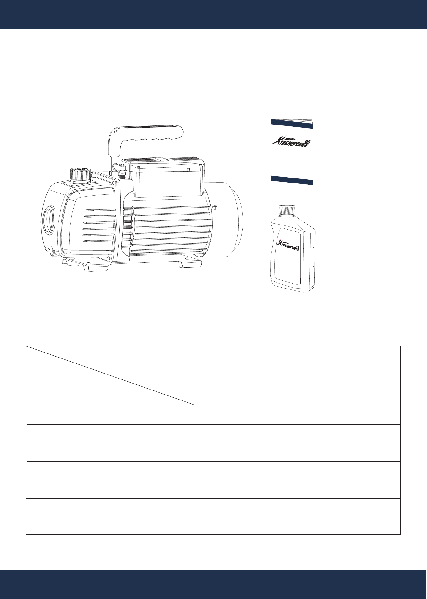
PACKAGE CONTENTS
3.5 CFM REFRIGERATION VACUUM PUMP 1 PC(S)
VACUUM PUMP OIL
1 PC(S)
INSTRUCTION
MANUAL 1 PC(S)
SKU 71093 / 71095 / 71096
Flow Rate (CFM) -
110V / 60HZ
Ultimate Vacuum (PA) -
Partial Pressure
Ultimate Vacuum (Microns) -
Total Pressure
Power (HP) -
Hose Power
Rotating Speed (r/min) -
110V / 60Hz
Oil Capacity (ml / fl. oz.)
Dimensions (in) - Length x Width x height
SPECIFICATION
71093
3.5 CFM
VACUUM PUMP /
MANIFOLD GAUGE
SET
3.5
0.8
60
1/4
1720
250
ml
/ 8.45
fl. oz.
11” x 5” x 9”
VACUUM
PUMP OIL
Designed for Rotary
Vacuum Pumps
200ml
100ml
250ml
71096
3.5 CFM
VACUUM PUMP
3.5
0.8
60
1/4
1720
250
ml / 8.45 fl. oz.
11” x 5” x 9”
DESCRIPTION
SKU / MODEL
71095
4.5 CFM
VACUUM PUMP /
MANIFOLD GAUGE
SET
4.5
0.8
60
1/3
1720
200
ml / 6.7 fl. oz.
11” x 5” x 9”
OPERATING INSTRUCTIONS
TOOL SETUP
• Check the Oil Level: Before operating the vacuum pump, place it on a flat, level surface. Observe the Oil
Sight Glass and ensure the oil level is at the fill line.
• Add Oil if Needed: If the oil level is low, unscrew the Oil Fill Plug and add oil through the opening. Use a
low-viscosity vacuum pump oil, such as HFV-46.
• Inspect the "O" Ring: Each time the Oil Fill Plug is removed, inspect the sealing "O" Ring for tears, cracks,
or damage. Replace the "O" Ring if necessary to ensure a proper seal.
• Secure the Oil Fill Plug: After adding oil, replace the Oil Fill Plug and tighten it securely. This prevents oil
leakage under pressure during operation.
VACUUM PUMP OPERATING INSTRUCTIONS
• Check the Oil Level: Before operating the vacuum pump, check the oil level as explained in the Tool Setup
section above.
• Use One Inlet Fitting at a Time: Only use one inlet fitting at a time. Keep the other fitting capped when not
in use.
• Turn Off the System: Ensure the vehicle/appliance and AC system are turned OFF before starting.
• Connect the Manifold: Attach the R-12, R-22, R-134a or R-410a manifold to the AC drain port of the vehicle
or appliance.
• This is a quick-release fitting. The drain port is typically the lower of the two manifold ports and is located
downstream from the compressor. Refer to the vehicle/appliance owner’s manual for specific information.
• Recover the Refrigerant: Attach an AC refrigerant recovery system and drain the refrigerant.
• Check the Vacuum Level: Once a vacuum level of 26 to 28 in/hg is reached, stop and disconnect the recov-
ery system.
• Attach the Vacuum Pump: Attach the vacuum pump to the system and run it for 10 minutes to increase the
vacuum level further.
• Turn the Switch ON: Turn on the pump’s switch to start the operation.
• Build Vacuum Power: The vacuum will build for approximately 2 minutes before reaching full power. Allow
the pump to run for an additional 10 minutes to thoroughly remove moisture and gas from the system.
• Monitor the Gauge: Use a gauge (included 71093 / 71095) to check for negative pressure. Maintain this
reading for 10 minutes. If the pressure reading rises toward "0," there may be a leak in the system that needs
to be addressed.
• Close Valves and Shut Off the Pump: Close all manifold valves (sold separately) and turn off the pump’s
switch before disconnecting the hose from the vacuum fitting.
• Unplug the Power Cord: To prevent accidents, unplug the pump's power cord after use.
• Cool Down and Store: Allow the vacuum pump to cool down completely before wiping it clean and storing
it indoors, out of reach of children.
Important Safety Reminder: Always exercise extreme caution when following these
instructions to ensure the safe operation of your vacuum pump.
OPERATION
6
BEFORE USE INSTRUCTION
WARNING
• Fill the Vacuum Pump with Oil: Unscrew the oil filling port/oil gas separator on models 71093, 71095, and
71096. Fill the pump with TW vacuum pump oil.
• Examine the Oil Level: always check the oil level before each use to ensure it is not below the minimum
oil level mark. Use TW vacuum pump oil for optimal performance.
• Secure the Oil Filling Port: After filling, screw the oil filling port/oil gas separator back on tightly to prevent
leaks.
PPE
WARNING
7
OPERATION
FEATURES
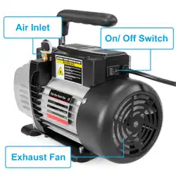
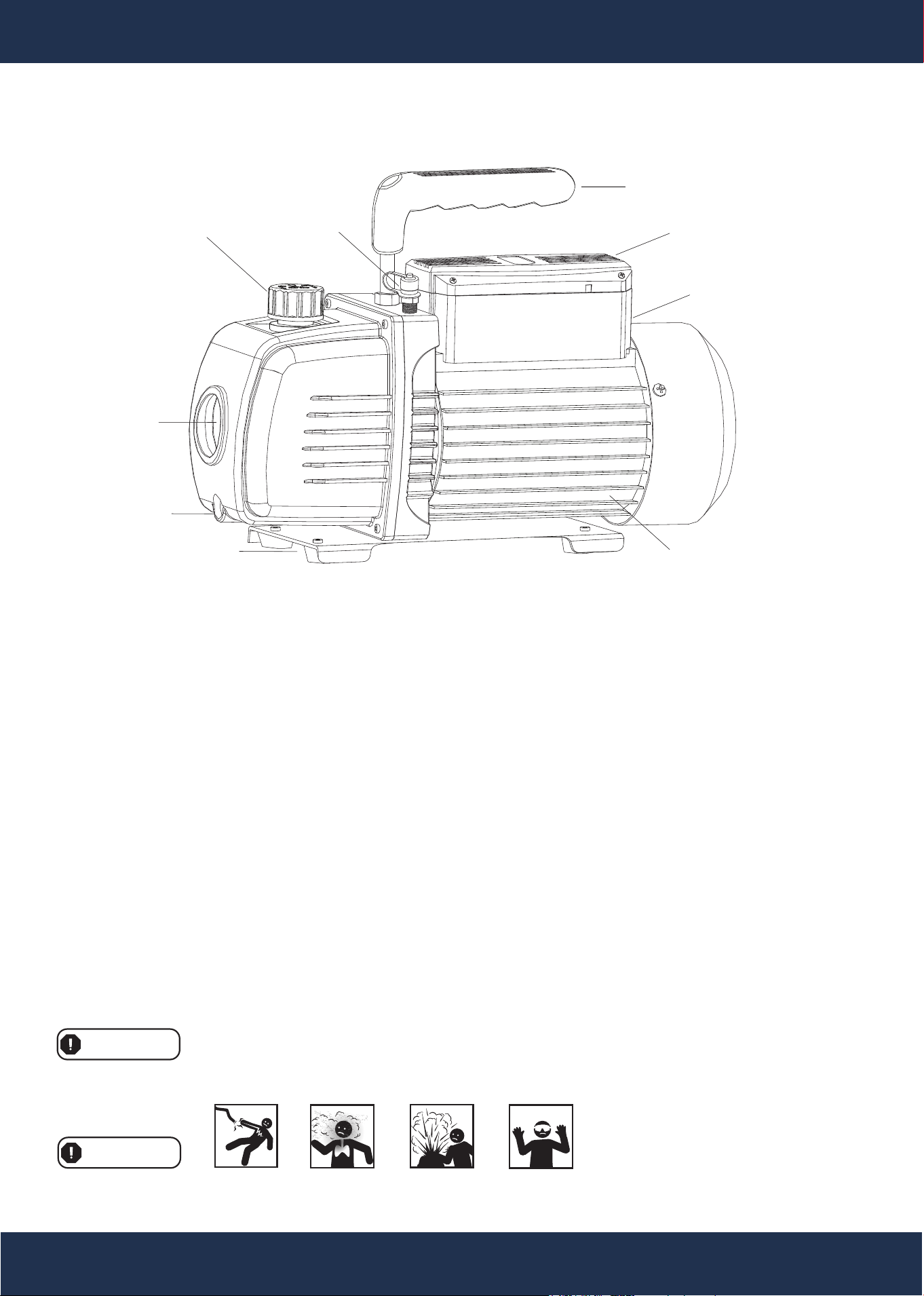
COMPONENTS AND FUNCTIONS
OIL LEVEL
SIGHT GLASS
OIL/GAS SEPARATOR
HANDLE
POWER SWITCH
MOTOR
ELECTRICAL BOX
BASEBOARD
OIL PLUG
GAS INLET
1. Anti-Backflow Design: The gas inlet passage is specially designed to prevent oil from flowing back,
protecting the container and hoses from contamination.
2. Forced Oil Cycling System: The pump is equipped with a forced oil lubrication system to ensure consistent
performance and durability.
3. Integrated Body Structure: The pump body features an integral cylinder block design, enhancing its ability
to achieve a high limiting vacuum.
4. Integral Handle: The handle is firm, comfortable, and durable, made with high-pressure rubber and a metal
insert for added strength.
5. Oil Level Sight Glass: The pump includes a large sight glass for easy oil level monitoring, preventing issues
caused by insufficient oil.
6. Large Starting Torque: This product can reliably start under conditions of low temperature (≥ 41°F) and
low voltage (≥ 103.5V), making it suitable for winter operation.
Always follow all safety precautions when diagnosing or servicing the tool.
Disconnect the power supply before performing any maintenance or service to prevent accidental operation.
WARNING
PPE
WARNING

14
SAFETY WARNINGS AND MAINTENANCE INSTRUCTIONS
INSPECTION BEFORE EACH USE
BEFORE EACH USE:
Inspect the general condition of the tool. Check for:
• Loose hardware
• Misalignment or binding of moving parts
• Cracked or broken parts
• Damaged electrical wiring
• Any other condition that may affect safe operation
AFTER USE:
• Wipe the external surfaces of the tool with a clean cloth to remove dirt and debris.
Oil Maintenance:
• Ensure the oil level is at the correct level indicated on the oil sight glass.
• Do not let the pump operate without oil.
• Keep the oil clean. If the oil becomes dirty, muddy, or contaminated with water or other volatile substances,
its performance will be affected, and it must be replaced.
Oil Replacement Procedure:
• Before replacing the oil, run the pump for about 30 minutes to thin the oil.
• Turn off the pump and drain the oil through the oil drain plug.
• Open the gas inlet and run the pump for 1-2 minutes. During this time, add a small quantity of clean
oil through the gas inlet to flush out residual oil.
• Ensure the pump is clean before proceeding.
• Reinsert the oil drain plug and fill the pump with clean oil through the gas inlet until it reaches the correct
oil level.
CLEANING PROCEDURE
Check General Condition:
• Inspect the A/C Vacuum pump for signs of wear or damage, including:
Cracked or broken parts.
Damaged components.
Any other condition that may compromise safe operation.
Do Not Use Damaged Equipment:
• If any issue is found during inspection, have the equipment repaired or replaced before further use.
STORAGE GUIDELINES
Storage Conditions:
• After use, ensure the equipment is clean and completely dry before storage.
• Store the set in a clean, dry location to prevent contamination and corrosion.
• If the pump will not be used for an extended period:
• Cover the oil cap and exhaust cap to prevent contamination.
• Store the pump in a dry location to protect it from moisture.
Repair Instructions:
• Repairs should only be performed by a qualified service technician to ensure proper functionality and safety
8
MAINTENANCE
• To Prevent Serious Injury from Accidental Operation: Turn the tool’s power switch OFF and unplug the
tool from its electrical outlet before performing any inspection, maintenance, or cleaning procedures.
• To Prevent Serious Injury from Tool Failure: Do not use damaged equipment. If abnormal noise or vibra-
tion occurs, stop using the tool immediately and have the problem corrected before resuming use.
Before proceeding with re-assembly, note the following safety guidelines. This product must
be installed and serviced exclusively by a qualified technician.
WARNING
9
MAINTENANCE
Regular inspection, cleaning, and proper storage of the A/C Manifold Set are essential for
maintaining its safety and functionality. Adherence to these procedures ensures the
equipment operates reliably and reduces the risk of failure during use.
WARNING
PROBLEM POSSIBLE CAUSE LIKELY SOLUTIONS
Tool will not start Cord not connected. Ensure the cord is securely plugged-in.
No power at outlet.
Check for power at the outlet. If the outlet is
unpowerd:
• Turn off the tool and check the circuit
breaker.
• If the breaker is tripped, ensure the circuit
capacity matches the tool and that no other
loads are present.
Internal damage or wear (e.g.,
carbon brushes or switch).
Have a qualified technician inspect and
service the tool.
Tool operates slowly or
overheats
Extension cord too long or wire
size too small.
Eliminate the use of an extension cord. If
one is necessary:
• Use a shorter, heavier-gauge cord. Refer
to the Extension Cords section in the
Grounding instructions.
Excessive noise or ratting
Internal damage or wear (e.g.,
carbon brushes or switch).
Have a qualified technician inspect and
repair the tool.
Low degree of Vacuum Lack of oil.
Add oil to the proper level above the oil-level
line.
Oil is not clean. Replace with clean oil.
Oil inlet is blocked. Clean the oil inlet or filter.
Hoses or gas inlet are clogged. Check and clear the connecting pipes.
Pump is not suitable for the
application.
Use a pump that is suitable for your specific
application.
Damaged oil seal. Replace the oil seal.
Loose or worn housing gasket. Replace the housing gasket.
Oil Spray Excessive oil in the pump. Adjust oil to the proper oil-level line.
Excessive pressure at the gas
inlet or over-pumping.
Switch to a larger pump.
Starting Difficulty Oil temperature is too low. Start the pump several times to warm the
oil.
Electrical malfunction.
Check for electrical issues and have them
repaired.
Foreign matter in the pump. Inspect and remove any foreign matter.
Excessive Noise Loose components. Tighten all screws and components.
Foreign objects or debris in or
around the pump.
Remove any debris or foreign objects.
TROUBLESHOOTING
REPLACEMENT PARTS
10
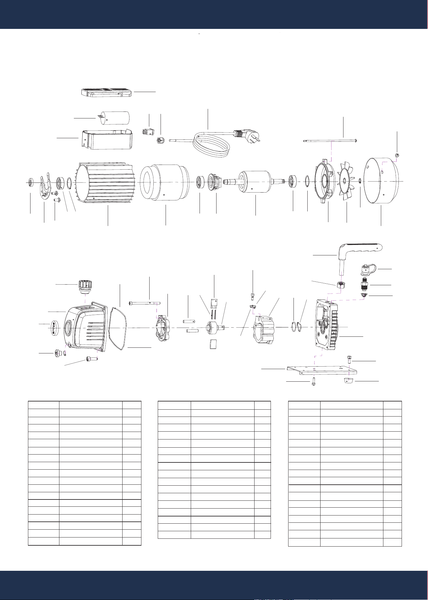
REPLACEMENT PARTS
PARTS DIAGRAM
ITEM NO.
1
2
3
4
5
6
7
8
9
10
11
12
13
14
15
16
17
18
DESCRIPTION
BASEBOARD
SCREW
RUBBER FEET
SCREW
BRACKET
STAINER
INLET FITTING
CAP
HANDLE
SCREW
O-RING
O-RING
PUMP STATOR
EXHAUST VALVE CORE
CAP BOARD
SCREW
PUMP ROTOR
ROTARY-WAY
QTY
1
2
4
4
1
1
1
1
1
1
1
1
1
1
1
1
1
2
DESCRIPTION
SPRING
STRAIGHT PIN
BACK COVER
SCREW
O-RING
OIL GAS SEPARATOR
OIL TANK
SIGHT GLASS
OIL DRAIN PLUG
O-RING
SCREW
OIL SEAL
CENTRIFUGAL PLATE
SCREW
BEARING
BEARING WASHER
MOTOR COVER
DESCRIPTION
MOTOR STATOR
BEARING
CENTRIFUGE
MOTOR ROTOR
BEARING
WAVEFORM GASKET
MOTOR COVER
FAN
SNAP RING
FAN COVER
SCREW
SCREW
JUNCTION BOX BASE
CAPACITOR
JUNCTION BOX COVER
SWITCH
PLY-YARN DRILL
POWER CABLE
ITEM NO.
19
20
21
22
23
24
25
26
27
28
29
30
31
32
33
34
35
QTY
1
1
1
1
1
1
1
1
1
1
8
3
1
1
1
1
1
1
ITEM NO.
36
37
38
39
40
41
42
43
44
45
46
47
48
49
50
51
52
53
QTY
2
2
1
3
1
1
1
1
1
1
4
1
1
2
1
1
1
50
3334
35 36
37 38
39
46
45
44
4342
4140
50
49
41
53
52
51
32
30
22
26
25
5
9
3
4
2
1
10
6
7
8
11
1213
14
27
23
15
16
17
18
19
20
21
21212121
28
29
24
31

DISCLAIMER
PLEASE READ THE FOLLOWING CAREFULLY
The manufacturer and/or distributor have provided the parts list and assembly diagram in this manual for
reference purposes only. They do not make any representation or warranty to the buyer that they are qualified
to make repairs to the product or replace any parts of the product. In fact, the manufacturer and/or distributor
expressly state that all repairs and parts replacements should be undertaken by certified and licensed
technicians, and not by the buyer.
The buyer assumes all risk and liability arising from their repairs to the original product or replacement parts or
arising from their installation of replacement parts. It is strongly advised that qualified professionals handle any
repairs or replacements to ensure safety and proper functioning of the product. Improper installation and
operation may result in injury, property damage, or voiding of warranty. The manufacturer and/or distributor shall
not be held responsible for any accidents, damages, or malfunctions resulting from the buyer's installation and
operation of the product. It is essential to follow all safety guidelines and recommendations provided in this
manual and to seek professional assistance if unsure about the installation or operation procedures.
CUSTOMER SERVICE
If you have any questions about ordering our pumps and replacement parts or other products, please feel
free to contact us using the following contact information:
Customer Service and Technical Support
Phone: (909) 628-0880
Email: [email protected]
Hours of Operation: Monday – Friday, 9AM – 4PM (CST)
11
DISCLAIMER
