3.5/4.5 CFM REFRIGERANT PUMP MANIFOLD GAUGE
SKU: 71093 / 71095
INSTALLATION AND USER’S GUIDE
Read all safety warnings and instructions.
Failure to follow the warnings and instructions may result in electric shock,
fire and/or serious injury.
Save all warnings and instructions for future reference.
DANGER
71095
psi
psi
Hi
Lo
High
Low
71093

THIS PAGE INTENTIONALLY LEFT BLANK
CUSTOMER SERVICE
If you have any questions about ordering our pumps and replacement parts or other products, please feel free
to contact us using the following contact information:
Customer Service and Technical Support
Phone: (909) 628-0880
Email: [email protected]
Hours of Operation: Monday – Friday, 9AM – 4PM (CST)
TABLE OF CONTENTS
CUSTOMER SERVICE
Customer Service and Technical Support
IMPORTANT SAFETY INSTRUCTIONS
Legends and Symbols
GENERAL SAFETY
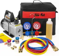
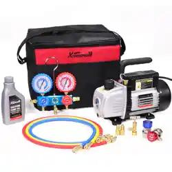
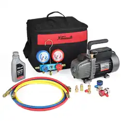
OVERVIEW (PRODUCT INFORMATION)
PACKAGE CONTENTS
REPLACEMENT PARTS
DISCLAIMER
Parts Diagram
INSPECTIONS
CLEANING PROCEDURES
1
1
1
2
2
3-4
5
5
5
6
6-7
8
8
9
9
9
9
9
10
10
11
TABLE OF CONTENTS
OPERATION
MANIFOLD OPERATING INSTRUCTIONS
MANIFOLD COMPONENT DESCRIPTIONS AND INSTRUCTIONS
MAINTENANCE
GENERAL MAINTENANCE AND SAFETY PROCEDURES
STORAGE GUIDELINES
1
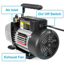
COMPONENTS AND FUNCTIONS
SPECIFICATIONS
ATTENTION INSTALLER: This manual contains vital information regarding the installation, operation, and safe
use of this gauge. It is essential to provide this manual to the end user of the product. Failure to read and follow
all instructions could lead to severe injuries.
USE OF NON-XTREMEPOWERUS REPLACEMENT PARTS VOIDS WARRANTY
DANGER: Ignoring these hazards can result in death, severe personal injury, or significant
property damage.
WARNING: Indicates potential hazards that can result in severe personal injury, death, or
significant property damage. Ignoring these warnings presents a real danger.
CAUTION: Indicates potential hazards that can result in minor or moderate personal injury,
property damage, or actions that are unpredictable and unsafe. Ignoring these cautions
presents a potential hazard.
NOTICE: This label indicates important special instructions that are not directly related to
hazards.
This guide provides instructions for installing and using the manifold gauge. If you have any questions about the
equipment, please contact XtremepowerUS.
This guide contains important information about safely installing and operating this product. After installation,
make sure to share this information with the owner/operator or leave it with them for their reference.
Legends and Symbols
When you come across the safety-alert symbol on your equipment or in this manual, pay attention to the
following signal words and remain vigilant about the potential for personal injury.
IMPORTANT SAFETY INSTRUCTIONS
WARNING
CAUTION
NOTE
Failure to comply with all instructions and warnings may lead to severe bodily injury or even
death. For optimal safety and functionality, it is advisable to have the product installed and serviced by a certified
service professional. Prior to using this product, installers, operators, and owners must carefully review these
warnings and all instructions provided in the owner’s manual. It is essential to leave these warnings and the
owner’s manual with the owner for their reference and safety.
CAUTION
To minimize the risk of injury, do not allow children to use on this product. Always supervise
children closely. CALIFORNIA PROPOSITION 65 - This product contains chemicals known to the state of
California to cause cancer and birth defects or other reproductive harm.
CAUTION
This manifold is designed exclusively for use by technically trained refrigeration and air
conditioning service technicians. Due to the extremely high pressure and hazardous gases present in all
systems, misapplication could result in serious injury or death.
The manufacturer strongly warns against the sale or use of this product by anyone other than professionally
trained personnel.
WARNING
2
IMPORTANT SAFETY INSTRUCTIONS
DANGER
WARNING
TO PREVENT EXPLOSION AND DEATH
• Air conditioning system service must be performed only by trained and experienced technicians to avoid
overfilling. Technicians opening the refrigeration circuit in automotive air conditioning systems MUST be
certified in refrigerant recovery and recycling procedures, in compliance with Section 609 of the Clean Air Act
Amendments of 1990. For additional information regarding ozone depletion and air conditioning service
regulations, visit the EPA’s website: www.epa.gov/ozone.
• Do not open the red HP Manifold Valve unless specifically instructed to do so during the recovery/evacuation
procedure. Refrigerant is under high pressure.
• Never attempt to add refrigerant through the HP (High-Pressure) side of the system, as this may cause the
refrigerant can to explode.
WARNING
Wear Safety Equipment
• Always wear ANSI-approved safety goggles and heavy-duty work gloves during setup.
• Wear goggles when working with refrigerants. Contact with refrigerants may cause serious injury.
• Wear gloves when working with refrigerants to prevent chemical burns or other injuries.
Prevent Leaks or Explosions
• Incorrect use or connections may cause leaks or explosions.
• Read and follow the instructions carefully and take all precautions to avoid leaks or explosions.
• Confirm that all associated devices are properly grounded before use.
California Proposition 65 Warning
• This product contains chemicals known to the State of California to cause cancer, birth defects, or other
reproductive harm.
Operate Only in a Well-Ventilated Area
• Ensure sufficient airflow to avoid the accumulation of refrigerant gases, which can displace oxygen and
pose serious health risks.
Avoid Moving Engine Parts
• Keep the gauge and hoses securely positioned away from any moving engine components to prevent
damage and injury.
Turn Off Engine and A/C System Before Setup
• Always turn off the vehicle's engine and air conditioning system before attaching the gauge to ensure safe
handling.
For Professional Use Only
• This manifold is designed exclusively for use by technically trained refrigeration and air conditioning service
technicians.
• Due to the unusually high pressure and presence of hazardous gases in all systems, misapplication could
result in serious injury or death.
• The manufacturer strictly warns against the sale of or use of this product by anyone other than
professionally trained personnel.
Certified Technician Requirement
• The procedure outlined is to be performed only by technicians certified in refrigerant recovery and recycling
procedures, as detailed in compliance with the Clean Air Act Amendments of 1990.
3
IMPORTANT SAFETY INSTRUCTIONS
TO PREVENT SUDDEN LOSS OF CONSCIOUSNESS AND DEATH
• Do not open the red HP Manifold Valve unless specifically instructed to do so during the recovery/evacuation
procedure.
• Refrigerant is under high pressure.
• Never attempt to add refrigerant through the HP (High-Pressure) side of the system, as this may cause the
refrigerant can to explode.
WARNING
TO PREVENT PERSONAL INJURY AND DEATH
IMPORTANT SAFETY NOTICE
• Read All Safety Warnings and Instructions - Failure to follow these warnings and instructions may result in
injury and/or property damage.
• Save These Warnings and Instructions - Retain this manual for future reference to ensure safe and proper
operation.
• The warnings and safety instructions in this manual are not intended to cover all possible conditions and
situations that may arise. Use common sense, caution, and care when operating or cleaning tools and
equipment.
• Always contact your dealer, distributor, service agent, or manufacturer regarding any problems or conditions
you do not understand before operating the product.
WARNING
SAVE THESE INSTRUCTIONS FOR FUTURE REFERENCE
Read all safety warnings and instructions.
Failure to follow the warnings and instructions may result in serious injury.
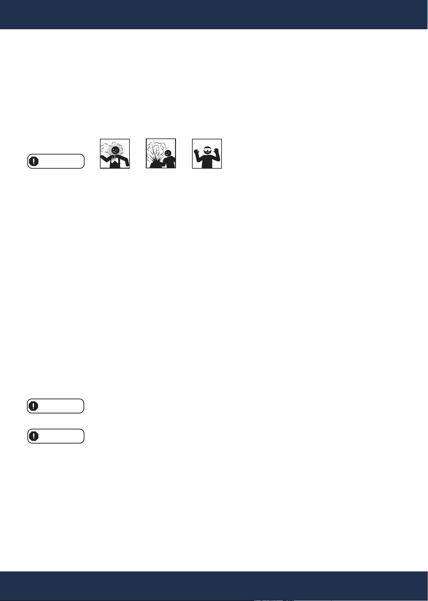
INHALATION HAZARD
HIGH PRESSURE HAZARD
PERSONAL PROTECTIVE EQUIPMENT REQUIRED
4
IMPORTANT SAFETY INSTRUCTIONS
4
PPE
IMPORTANT SAFETY NOTICE
• Do Not Exceed Range Limit: Do not exceed 80% of the claimed range of the manifold when in use.
• Proper Operation Required: Improper operation may lead to leakage or personal injury.
• Follow the Manual: Carefully read the manual and operation instructions for the manifold or associated
equipment before use.
Refrigeration Gauge Calibration
• The refrigeration gauge has been pre-calibrated at the factory. However, due to handling and shipping, it may
require adjustment.
Adjustment Procedure:
1. Unscrew the center screw and hold it firmly using a screwdriver.
2. With your thumb and forefinger, grip the pointer near its center.
3. Gently turn the pointer to align with the zero mark.
4. Repeat this process carefully if the pointer does not align to zero.
WARNING
5
OVERVIEW (PRODUCT INFORMATION)
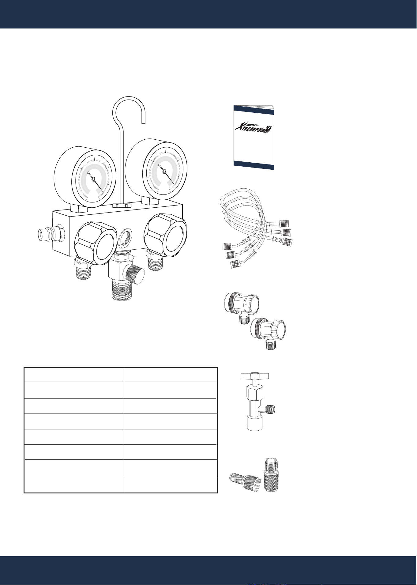
PACKAGE CONTENTS
PARTS # 54 MANIFOLD GAUGE 1 PC(S)
PARTS # 56
R134A QUICK COUPLERS
2 PC(S)
PARTS # 55
CHARGING HOSE
(BLUE, RED, YELLOW)
3 PC(S)
PARTS # 58
SAE ADAPTER
2 PC(S)
INSTRUCTION
MANUAL 1 PC(S)
SKU 71093 / 71095
psi
psi
Lo
Hi
High
Low
PARTS # 57
CAN TAP
1 PC(S)
SPECIFICATION
Manifold Blue Gauge (Low):
Manifold Red Gauge (High):
Operating Pressure:
Burst Pressure:
Rotating Speed:
Ultimate Vacuum:
Gauge Reading:
Hose Length:
-30 - 550 psi
-30 - 760 psi
800 psi
4000 psi
1720 RPM
5 Pa
R12, R22, R134a, R410a
60 inch
MANIFOLD OPERATING INSTRUCTIONS
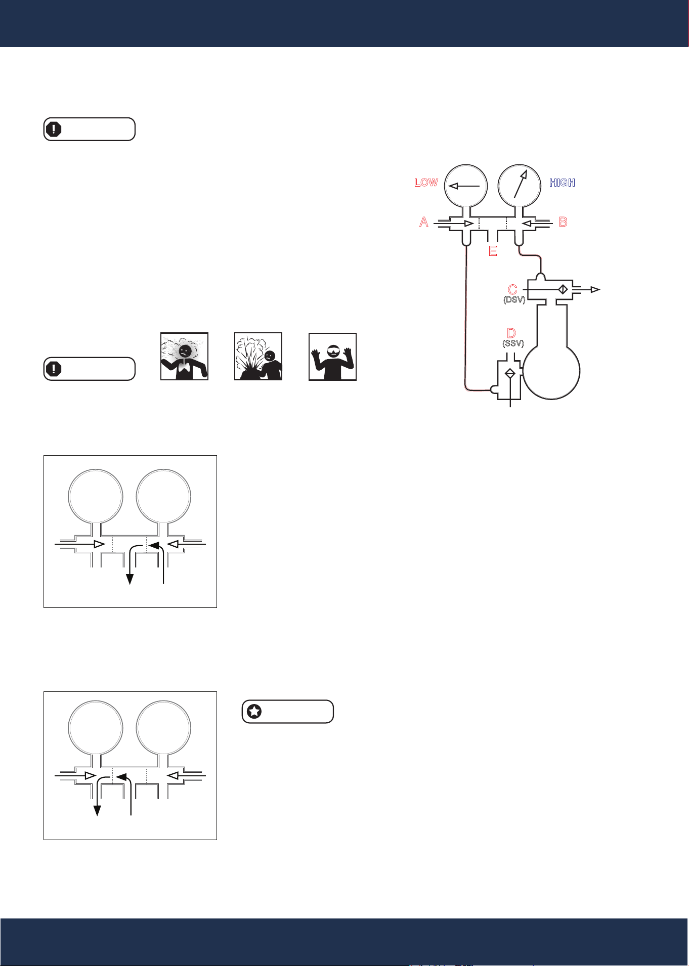
1. Purging
Purpose: To remove air and moisture from the manifold and lines.
Steps:
A. Ensure both manifold valves (A and B) are turned all the way in. The
system will now pump vapor, and both low and high-side pressures
can be read.
B. Attach the lines from the manifold to the SSV at D and leave the
connection one to two turns loose.
C. Tighten the line to the DSV at C.
D. Open both manifold valves (A and B) by 1/4 to 1/2 turn.
E. Cap the middle opening (E).
F. Slightly open the DSV (C) stem by 1/8 to 1/4 turn momentarily ("crack
the valve"). A high-pressure refrigerant surge will flow through the
lines and manifold, purging to the atmosphere at the loose D (SSV)
connection.
G. Tighten the loose connection at D (SSV) once purging is complete.
Purging should be minimized to avoid damage to the
atmosphere. Carefully test for leaks while the manifold
and lines are under high pressure. Correct any leaks immediately.
2. Observing Operating Pressures
Steps:
A. Close valve A completely (turn all the way in).
B. Close valve B completely (turn all the way in).
C. Slightly open the back seat of valve C (DSV).
D. Slightly open the back seat of valve D (SSV).
Important Safety Reminder: Always exercise extreme caution when following these
instructions to ensure the safe operation of your manifold gauge.
OPERATION
6
NOTE
PPE
WARNING
HIGHLOW
CHARGING OR ADDING OIL
HIGHLOW
PURGING
VALVE MUST BE CLOSED
The schematic below explains the installation of a gauge manifold
on an external drive compressor with service valves:
A: Manifold Suction Valve
B: Manifold Discharge Valve
C: Compressor Discharge Service Valve (DSV)
D: Compressor Suction Service Valve (SSV)
E: Service Opening.
SCHEMATIC OVERVIEW
WARNING
MANIFOLD OPERATIONS
A B
HIGHLOW
C
(DSV)
D
(SSV)
E
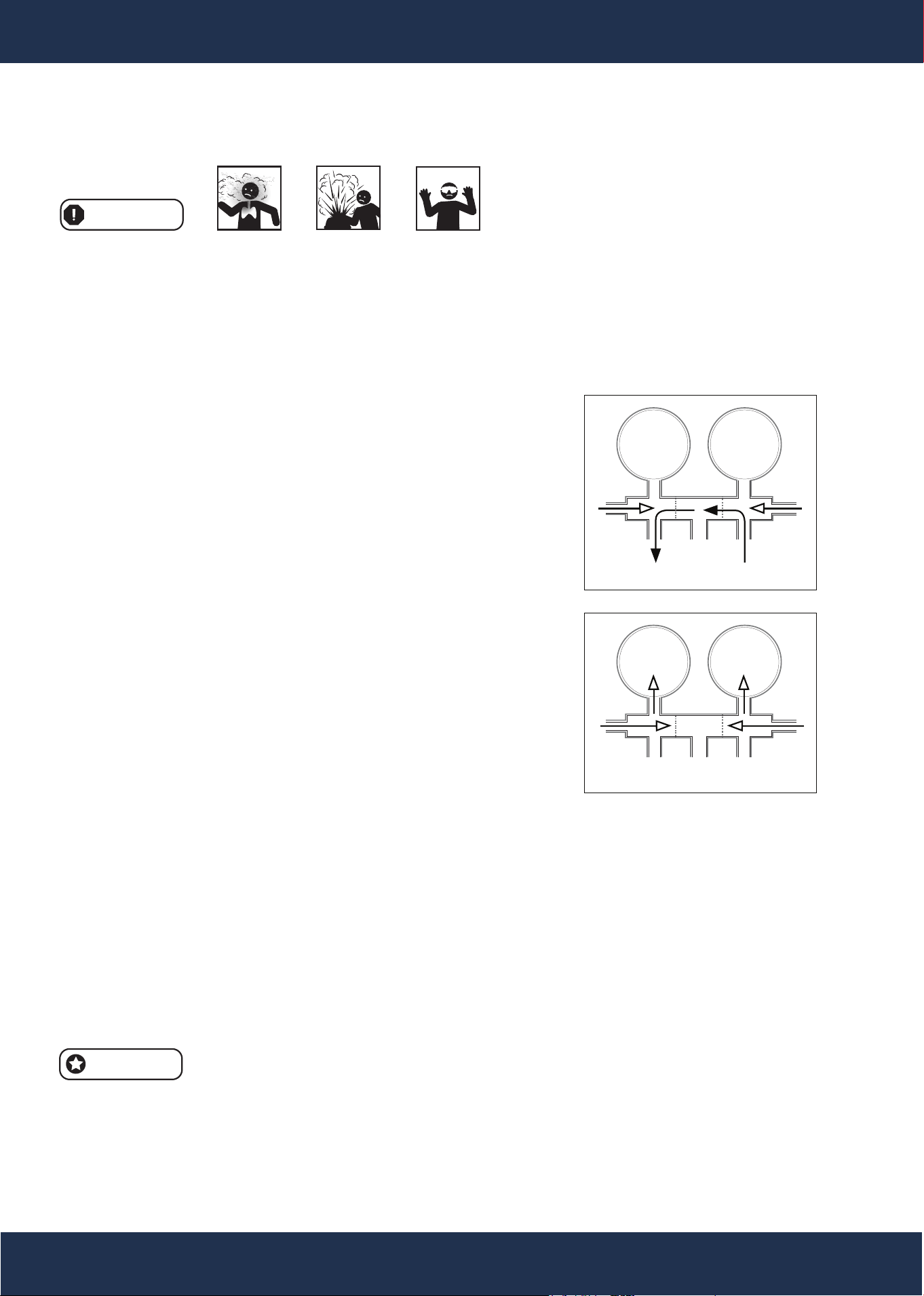
3. Refrigerant Charging (Vapor)
Steps:
A. Connect the refrigerant cylinder to E (vapor-only port).
B. Open valve A.
C. Close valve B.
D. Slowly close the front seat of valve D (SSV) to regulate the refrigerant flow.
4. Condenser Purging
Steps:
A. Close valve A.
B. Close valve B.
C. Slightly open valve C (DSV) to purge.
5. Liquid Refrigerant Charging (High Side)
Steps:
A. Connect the refrigerant cylinder to E.
B. Close valve A.
C. Open valve B.
D. Place valve C (DSV) in a mid-position.
6. Building Pressure in the Low Side
Purpose: For control setting or leak testing.
Steps:
A. Seal opening E with the seal cap.
B. Open valve A.
C. Close valve C (DSV).
Gauge Calibration
The refrigeration gauge is pre-calibrated at the factory.
However, due to shipping or handling, minor adjustments may be necessary:
Dry Gauge Calibration:
• Unscrew the lens.
• Hold the center screw firmly with a screwdriver.
• With your thumb and forefinger, grip the pointer near its center and gently turn it to align with zero.
• Repeat the process if the pointer does not align with zero on the first attempt.
Wet Gauge:
• Wet gauges do not require zeroing.
• Ensure manifold valves and service connections are handled with care to prevent leaks or contamina-
tion.
• Use this equipment in a well-ventilated area to avoid inhaling refrigerants.
• Always consult the manufacturer's instructions for specific refrigerant charge, oil change, and servicing
recommendations.
7
OPERATION
MANIFOLD OPERATING INSTRUCTIONS
PPE
WARNING
NOTE
HIGHLOW
GAUGE READING
HIGHLOW
BYPASSING
8
OPERATION
O
P
E
N
C
L
O
S
E
D
Lo
Hi
psi
psi
O
P
E
N
C
L
O
S
E
D
LOW-PRESSURE
(LP) BLUE SIDE
HIGH-PRESSURE
(HP) RED SIDE
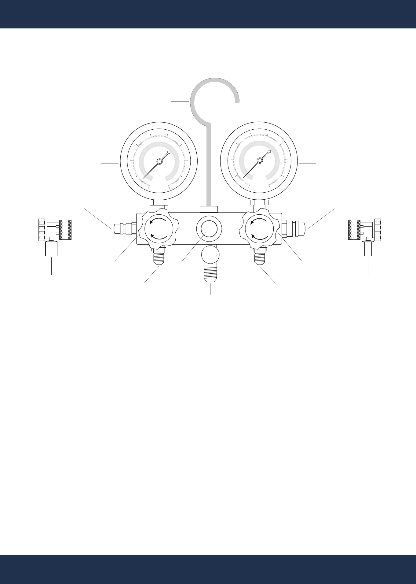
1. Blue LP Side Gauge: Used to measure the low-pressure side suction or pressure.
2. Red HP Side Gauge: Used to measure the high-pressure compressor discharge side pressure.
3. Manifold Service Valves: Control the flow of refrigerant to and from the Yellow Hose, also referred to
as the Charge Hose.
4. Coupler Valves: Regulate the flow of refrigerant to the Gauges from the Red and Blue Hoses.
5. Optical Sight Glass: Allows visual inspection of the refrigerant to check its appearance and condition.
6. Yellow Charge Hose: The Yellow Hose is versatile and serves three primary purposes:
a Refrigerant Recovery/Evacuation
b. Charging (filling) the system with refrigerant
c. System Checking: To minimize the risk of leaks,
connect the Yellow Hose to both branches of the T-fitting.
7. Charge Valve: Permits simultaneous connection to a refrigerant recovery system for efficient servicing.
8. General A/C Service Instructions: This manual outlines general procedures for servicing A/C systems.
For specific procedures tailored to the type and model of an A/C system,
consult the manifold manufacturer’s A/C system service manual.
9. Refer to Operating Instructions: Detailed instructions for operating the manifold set and performing
A/C system service are provided in the following sections.
OPTICAL
SIGHT GLASS
BLUE LP
SIDE GAUGE
RED HP
SIDE GAUGE
HANGING
HOOK
BLUE HOSE
(To Low Side)
YELLOW CHARGE HOSE
(Utility)
BLUE
COUPLER
VALVE
RED
COUPLER
VALVE
RED HOUSE
(To High Side)
BLUE LP MANIFOLD
SERVICE VALVE
RED HP MANIFOLD
SERVICE VALVE
Manifold Component Descriptions and Instructions
COMPONENTS AND FUNCTIONS
HP - High Pressure
LP - Low Pressure
BLUE COUPLER
STORAGE PLUG
RED COUPLER
STORAGE PLUG
14
PPE
GENERAL MAINTENANCE AND SAFETY PROCEDURES
Before proceeding with re-assembly, note the following safety guidelines. This product must
be installed and serviced exclusively by a qualified technician.
WARNING
9
MAINTENANCE
INSPECTION BEFORE EACH USE
WARNING
Routine Cleaning:
• Periodically clean the A/C Manifold Set using a damp cloth and a mild detergent or solvent.
• Avoid using harsh chemicals or abrasive materials to prevent damage to the equipment.
CLEANING PROCEDURE
Important Safety Notice:
• Any procedures not explicitly outlined in this manual must be must formed by a qualified technician to
ensure safety and proper operation.
Equipment Condition:
• Do not use damaged equipment. If abnormal noise, vibration, or leaking air/refrigerant is detected,
immediately stop using the equipment and address the issue. Ensure all problems are corrected
before resuming operation.
Check General Condition:
• Inspect the A/C Manifold Set for signs of wear or damage, including:
• Cracked or broken parts.
• Damaged Hoses.
• Any other condition that may compromise safe operation.
Do Not Use Damaged Equipment:
• If any issue is found during inspection, have the equipment repaired or replaced before further use.
STORAGE GUIDELINES
Storage Conditions:
• After use, ensure the equipment is clean and completely dry before storage.
• Store the set in a clean, dry location to prevent contamination and corrosion.
Prevent Contamination:
• Connect the Red Coupler and Blue Coupler to their respective Coupler Storage Plugs during storage.
Regular inspection, cleaning, and proper storage of the A/C Manifold Set are essential for
maintaining its safety and functionality. Adherence to these procedures ensures the
equipment operates reliably and reduces the risk of failure during use.
WARNING
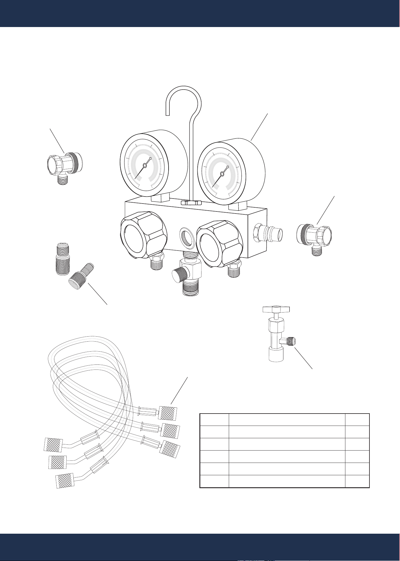
REPLACEMENT PARTS
10
ITEM
54
55
56
57
58
DESCRIPTION
MANIFOLD GAUGE
CHARGING HOSE - BLUE, RED, YELLOW
R134A QUICK COUPLERS - LOW, HIGH
CAN TAP
SAE ADAPTER
QTY
1
3
2
1
2
REPLACEMENT PARTS
PARTS DIAGRAM
psi
psi
Hi
Lo
High
Low
PARTS # 54
PARTS # 56
PARTS # 55
PARTS # 58
PARTS # 57
PARTS # 56

DISCLAIMER
PLEASE READ THE FOLLOWING CAREFULLY
The manufacturer and/or distributor have provided the parts list and assembly diagram in this manual for
reference purposes only. They do not make any representation or warranty to the buyer that they are qualified
to make repairs to the product or replace any parts of the product. In fact, the manufacturer and/or distributor
expressly state that all repairs and parts replacements should be undertaken by certified and licensed
technicians, and not by the buyer.
The buyer assumes all risk and liability arising from their repairs to the original product or replacement parts or
arising from their installation of replacement parts. It is strongly advised that qualified professionals handle any
repairs or replacements to ensure safety and proper functioning of the product. Improper installation and
operation may result in injury, property damage, or voiding of warranty. The manufacturer and/or distributor shall
not be held responsible for any accidents, damages, or malfunctions resulting from the buyer's installation and
operation of the product. It is essential to follow all safety guidelines and recommendations provided in this
manual and to seek professional assistance if unsure about the installation or operation procedures.
CUSTOMER SERVICE
If you have any questions about ordering our pumps and replacement parts or other products, please feel
free to contact us using the following contact information:
Customer Service and Technical Support
Phone: (909) 628-0880
Email: [email protected]
Hours of Operation: Monday – Friday, 9AM – 4PM (CST)
11
DISCLAIMER