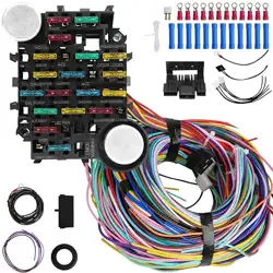
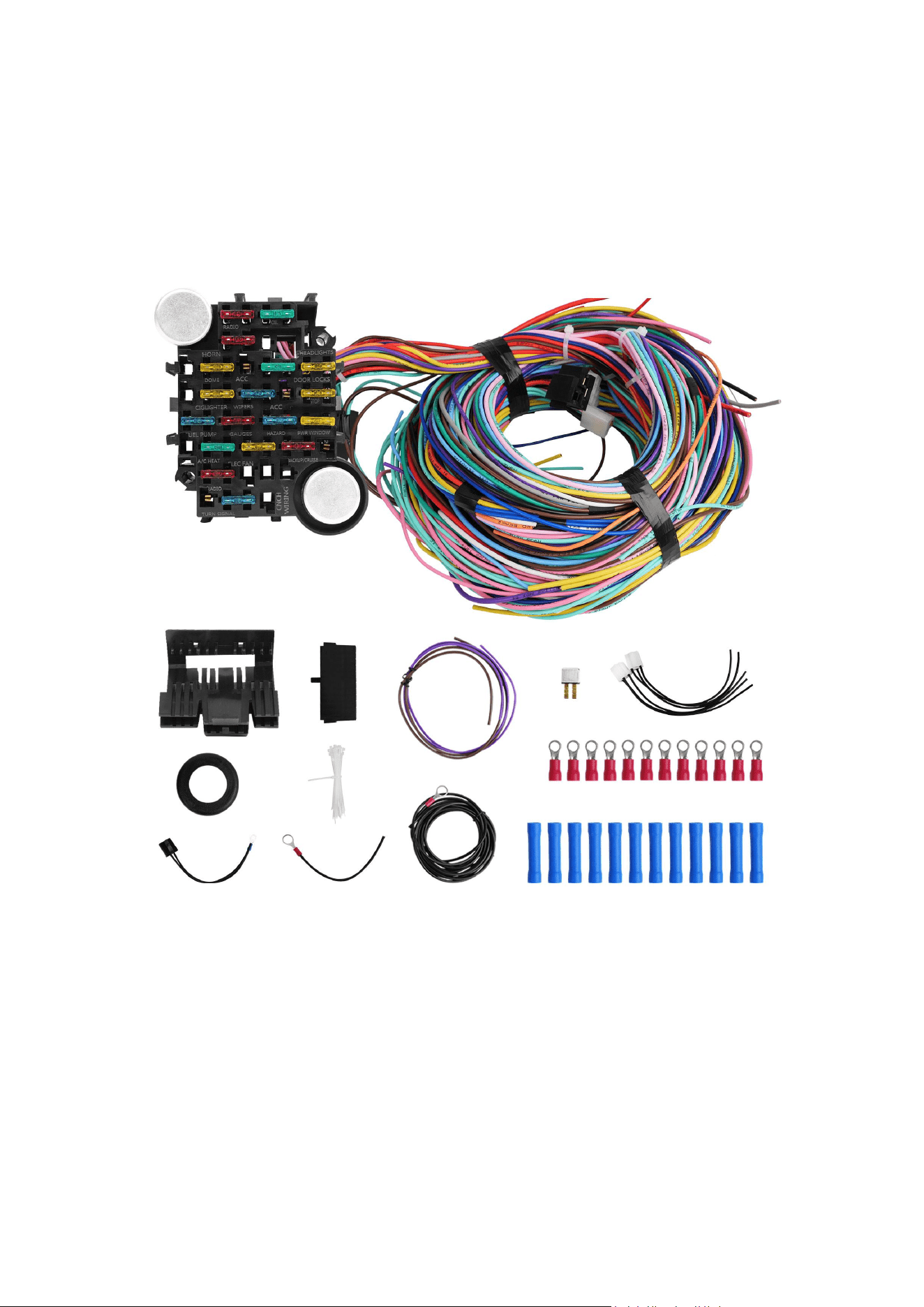
21 CIRCUIT WIRING HARNESS

THIS KIT CONTAINS THE FOLLOWING:
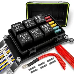
1 PRE-WIRED FUSE PANEL WITH 17 FUSES AND 1 BREAKER
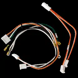
2 SIGNAL FLASHERS AND 1 PRE-WIRED RELAY CONNECTOR WITH HORN RELAY
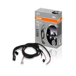
2 PRE-WIRED HEADLIGHT PLUGS
1 PRE-WIRED LATE GM ALTERNATOR PLUG
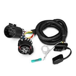
2 PRE-WIRED GM COLUMN IGNITION SWITCH PLUGS
1 PRE-WIRED DIMMER SWITCH PLUG
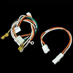
2 GM TURN SIGNAL CONNECTORS FOR THE PRE-TERMINATED WIRES (3 7/8AND 41/4)
1 FUSIBLE LINK (3"BLACK WIRE WITH RING TERMINAL)
1 LARGE GROMMET
30 PLUS MISCELLANEOUS INSULATED TERMINALS AND SOME SMALL CABLE TIES
2 LOOSE WIRES (NEUTRAL SAFETY SWITCH WIRE AND PANEL LIGHT WIRE)
STEP #1 READ THESE INSTRUCTIONS
Before starting this installation. These instructions were developed after installing this system in
over a dozen different vehicles
To aid you we have used BOLD PRINT to note IMPORTANT items and provided general diagrams
for FORD, GM and MOPAR. There is also a DO and DON’
T section that you may find useful, Please remember that these are GENERAL INSTRUCTIONS for
your UNIQUE and SPECIFIC vehicle and you may need to MODIFY them for your application.Als
o,whenever using AFTER-MARKET or SPECIALITY equipment, always use the diagrams PROVIDE
D WITH that equipment.
This WORKBOOK is designed for both our labeled and color-coded harnesses. Whenever a speci
fic wire is referred to, it will be displayed with its LABEL then it’
sCOLORYou are to use the destination that applies to the kit you purchased.If a diagram shows
ONLY a color OR a label,then that wire is NOT PROVIDED by this kit.An example of this would-b
e GROUND WIRES which we DO NOT provide We do recommend to use black for ground wires
on our color-coded harness and white on oun labeled black harness to eliminate possible confu
sion.
Remember this is a WORKBOOK!!! So, make use of the blank space we provide for your notes W
rite things down so you don't forget.

STEP #2 COMPLETE THE WORK SHEET
At the back of this workbook. This should be done while looking at the vehicle, so that you can i
dentify what accessories you will be using and what switches will be necessary. Here is where A
LITTLE PLANNING WILL SAVE A LOT OF TIME.
The WORK SHEET has been divided into the same 4 basic sections that make-up your harness. T
hey are the FRONT SECTION,DASH SECTIONSTEERING COLUMN SECTION and TAIL SECTION.
For each section compare the list of wires to your application and note if it will be USED MOVED
OR REMOVED. Before marking wires to be removed consider accessories you may want to add l
ater on those not provided for by this kit. The design of your vehicle may require some of the wi
res to be moved from one section to another.(An example of this would be, if the horn was mou
nted on the rear of the car, you would want to move the HORN=GREEN wire to the tail section.)
When marking a wire to be moved DONT FORGET to WRITE IT into the new section in the extra
spaces provided. The extra spaces should also be used for any extra wires you may need to add,
such as ground wires.
STEP #3 PREPARE THE HARNESS FOR INSTALLATION
For this you will need a LARGE CLEAR WORK AREA to spread out the harness.(The floor next to
the project car works well.) Your harness, as purchased,will have each of the 4 SECTIONS coiled
and tied with cable ties. When working with the harness, it is VERY IMPORJTANT NOT TO
REMOVE THE 3 CABLE TIES CLOSEST TO THE FUSE PANEL.
Start with the largest coil of wires. That will be the FRONT SECTION,so remove the cable ties and
uncoil the wires toward the front of the vehicle The next largest coil of wires will be the TAIL
SECTION. Cut off the cable ties and uncoil those wires toward the rear of the vehicle. The
remaining coils of wires are the DASH SECTION and the STEERING COLUMN SECTION.The
STEERIG COLUMN SECTION is the one with the pre-attached plugs and will not need to be
changed in most applications Remove the cable ties from the DASH SECTION and uncoil those
wires to the side of the FUSE PANEL

Now using the WORK SHEET that you completed in STEP #2, start by removing any unused wires.
Work one section at a time and remove those wires ONE WIRE AT A TIME by pulling them
through the remaining harness cable ties.(REMEMBER DO NOT REMOVE THE 3 TIES NEAREST
THE FUSE PANEL) Unused wires that come directly from the FUSE PANEL are HOT LEADS and
should be cut as ClOSE to the back of the panel as possible.Use CAUTION and only cut wires that
you are sure you will NEVER NEED!
After removing all unused wires from all sections, move on to those wires that you noted you
would have to move from one section to another. Working one wire at a time move those wires to
their new sections by pulling them out of their original section and passing them through the
harness ties into their new sections.
Now, a section at a time, add any wires you noted you would need that are NOT PROVIDED in
your kit.(Note you can use the wire you removed,but KEEP NOTES so as not to get CONFUSED.)
The last part of this step is to compare the WORK SHEET to the harness as you have it now
prepared. if everything is accounted for, use cable ties and recoil the sections one at a time. If the
ties nearest the panel are loose either tighten them or replace them as necessary.
STEP #4 MOUNTING THE FUSE PANEL
The FUSE PANEL of our standard harness is designed to be mounted under the dash on the
driver's side of the vehicle.
The FUSE PANEL should be mounted securely to a FLAT SURFACE.Care should be taken to keep it
and the wires away from MOVING OBJECTS such as gas and brake controls and the panel
SHOULD BE ACCESSIBLE in case you ever blow a fuse. When selection the panel location make
sure that the STEERING COLUMN SECTION WILL REACH YOUR COLUMN.
After selecting the location for the FUSE PANEL, determine the best place to mount the horn relay
that's pre-wired to the panel. We have provided ample length so that you may mount the relay
anywhere near the panel.
Now that the FUSE PANEL and HORN RELAY are mounted,note where the FRONT SECTION wires
exit the panel. Find a spot on the fire wall where these wires can enter the ENGINE
COMPARTMENT without interfering with other components, such as brake boosters, wipers, the
engines, steering gear, etc.At that spot drill, a 11/4”HOLE and install the grommet provided in
your kit.
As the last part of this step, remove the cable ties you put on the FRONT SECTION wires and pass
them through the grommet into engine compartment ONE WIRE AT A TIME.

STEP #5 ROUTING AND ATTACHING THE WIRES.
In this step, you will be completing the job by terminating all those loose ends. As before this will
be done section by section. We suggest you start with the TAIL SECTION and end with the DASH
SECTION. Each section has its own set of instructions and we suggest you review the DO and
DON’T page and your WORK SHEET before staring each section.As you complete each section
use cable ties to group the wires together and at points where wires branch off from the harness.
The TAIL SECTION harness is designed to be routed to the back of the vehicle inside along the
floor The wires can be taped to the floor or run under the driver’s side door sills. They need to be
routed where they WON’T BE WALKED ON and where the seats won’t interfere. At the rear of the
vehicle you will attach the wires to your lights, gas tank sender, and fuel pump as indicated on the
TAll SECTION DIAGRAM. Please note also that the DOME LIGHT power wire is included in the TAil
SECTION.
The FRONT SECTION wires include the front lighting, engine and accessories normally mounted
or the front of the vehicle. For this section start by separating the EIGINE wires from the
rest.When installing the front lighting and accessory wires follow the FRONT LIGHTING DIAGRAM.
When installing the ENGINE,WIRING use the diagram from the FORD,GM or MOPAR section that
comes closest to your vehicle. Remember when connecting the 10GA.SOLENOID PWR=RED wire
to use the FUSIBLE LINK provided in your kitFailure to install the FUSIBLE LINK VOIDS ALL
WARRANTY ON this harness system. If you are using an AMP METER,please follow the AMP
METER section on the DASH DIAGRAM.
The STEERING COLUMN SECTION has the wires for your turn signals, ignition switch and dimmer
switch. The plugs on these wires are for a GM STEERING COLUMN that has a column mounted
ignition switch. lf you are using that type of column,plug the black and clear plugs into the
ignition switch. The dimmer switch plug will fit a floor mounted dimmer or the GM column
mounted dimmer The turn signal wires are pre-terminated and you will be using the diagram in
the GM SECTION to determine the correct plug and order that the wires should be installed. Note
that the plugs are letter coded to help.
If you are using a LATE MODEL GM VAN type column the turn signals will match the plugs in your
kit but you must use IGNITION SWITCH DIAGRAM in the DASH DIAGRAM.
If you are using a FORD or MOPAR COLUMN use the diagrams in the FORD and MOPAR
SECTIONS But REMEMBER because they change colors often,these interchanges may NOT match
your column If the colors don’t match or you’re using something not listed, you may have to sort
the turn signa wires out with an ohm meter. Most original ignition switches are marked on the
back of the switch.

The DASH SECTION contains the wires for the gauges, the headlight switch, radio power leads,
heater wiper and cooling fan switches. The order you install these wires depends greatly on your
dash configuration. Here it is best to start working from the driver's side of the dash toward the
passenger’s side. Use the cable ties provided in your kit to tie up the harness as you go.
By now you should be out of wires. All that remains is a simple start up procedure. Start by
turning OFF ALL ACCESSORIES.Place the ignition switch in the OFF position and close the doors
to make sure the dome light is off.Now connect the POSBATTERY CABLEBEFORE connecting the
NEG. CABLE,yOu should check for a current draw.This can be done easily with a test light
connected between the neg Battery post and the neg. Battery cable. No light-no draw. If you have
no draw or just a dim light, it is safe to connect the neg. Battery cable and start checking the
system.
We are sorry that this document is too large to be displayed in its entirety.
Please rest assured that our products come with instruction manuals.
Please contact us directly with any questions you may have.