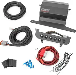
Voswitch 6-Switch Programmable Switch Panel Power System
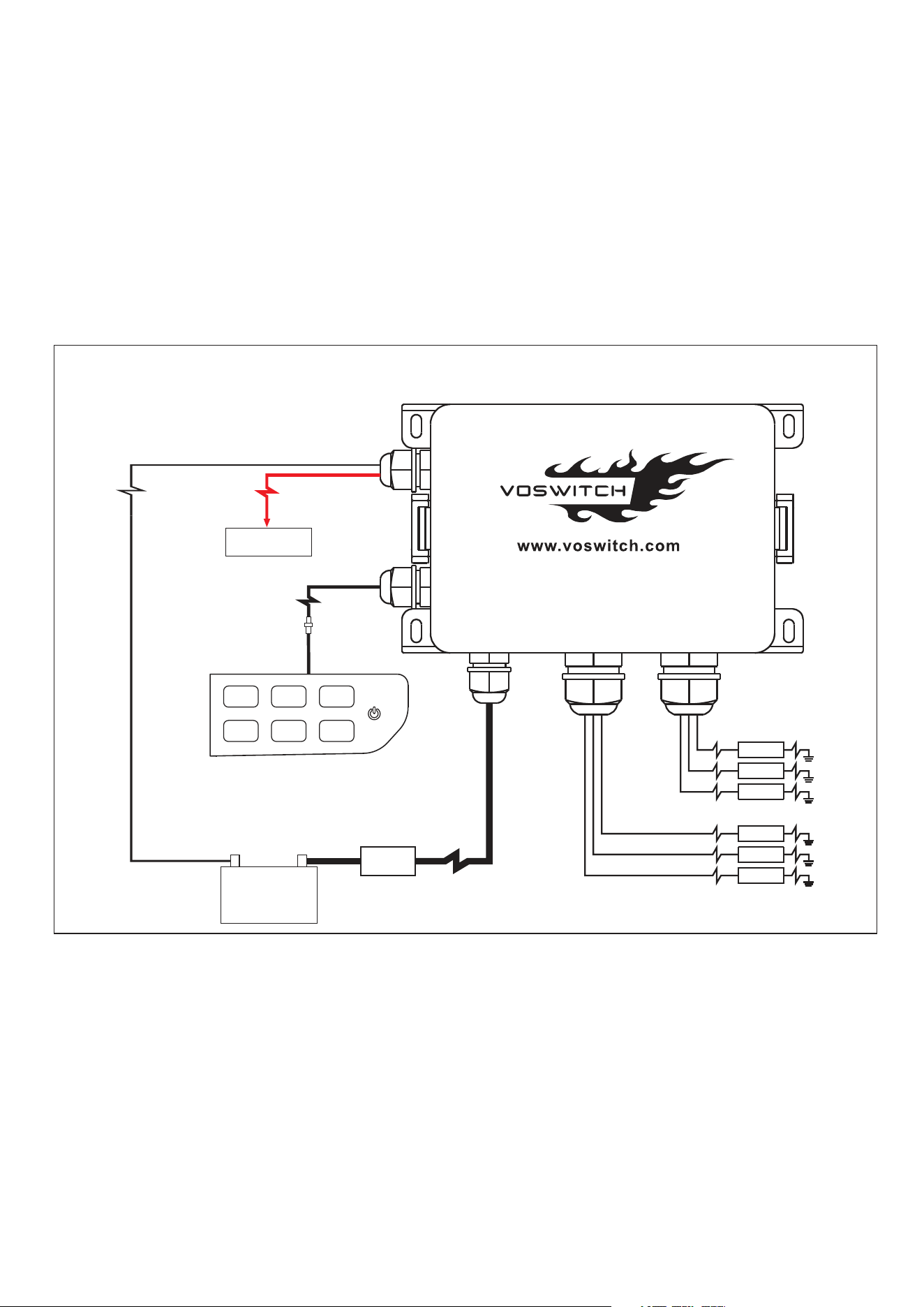
1. Connect the black ground wire directly to the Negative terminal of the battery. DO NOT connect to frame
ground studs or ground distribution studs.
2. Do not connect any other power feeds to the power module’s power stud.
3. Do not use the JL300 to control a winch. Use the winch manufacturer’s supplied device. Installation should
be performed by a qualified technician, to avoid damage to the system or output accessories.
The JL300 switch panel power system is fully programmable .
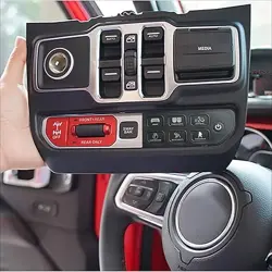
The switch panel has 6 switches and one programming/on-off switch. amber LEDs indicate when the switch is
turned on.
The power module has 6 outputs, switches 1 – 6 are rated at 30A.
The power module also has 1 input as trigger, you can hook the small red wire to ignition or ACC or headlight
through the add-a-circuit fuse tap supplied.
JL300
Overview
Read before installing!
Installation
Disconnect the negative battery lead from the vehicle’s battery before proceeding with installation, and to avoid
damage to the electrical system!
Tools needed: Dash trim removal tool ,Philips screw driver , 8mm Wrench/socket , 10mm Wrench/socket,
27mm Wrench
AUX1
AUX2
AUX3
AUX4
AUX5
AUX6
Wiring Diagram
100A
in-line fuse
+
_
12V Battery
To Keyed Fuse
(If needed)
1. Installing the Power Module on 2.0L /3.6L Engine Jeep JL or Gladiator
The power module should be mounted onto the top of the left fender.
the power module is manufactured with automotive rated electronic parts, with a temp rating of -40 C to 125 C.
remove the factory bolt from the top of fender, sit the bracket on the fender top, put the factory bolt and a M6 bolt
supplied back into the holes and tighten the 2 bolts. (See Figure 1-2)
1
Switch 6
Switch 3
Switch 4Switch 5
Switch 1Switch 2
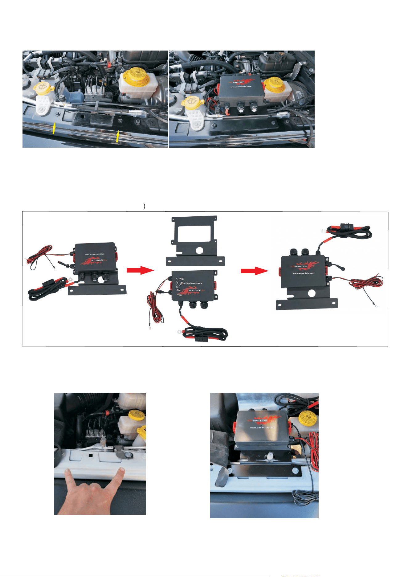
Figure 1
Figure 2
2. Installing the Power Module on EcoDiesel 3.0L Engine Jeep JL or Gladiator
2.1 The power module should be mounted onto the top of the left fender. the AC service port will be in conflict
with the cable glands, you need to remove the relay box from the bracket and rotate it 180 degrees then install it
back on the bracket. (see Figure 3-4)
2.2 Remove the factory bolt from the top of fender, sit the bracket on the fender top, put the factory bolt and
a M6 bolt supplied back into the holes and tighten the 2 bolts. (See Figure 4-5)
Figure 3
Figure 4
Figure 5
2
5.Installing the Battery Cable
Connect the battery cable to battery positive. Connect the ground wire to battery negative.
6.Connecting Accessories
Identify which accessories you will be powering with your Switch Panel Power System. Remember that
Switches 1-6 are limited to 30 amps. If your accessory current draw is very small, such as 10 A or 15 A, the
original 30 A fuse is too large to protect your accessory, so just change the 30 A fuse to 10 A or 15 A to match
your accessory fuse rating.
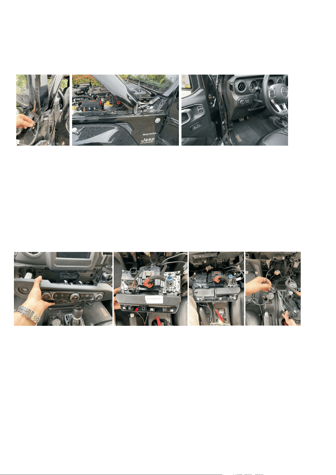
3.Installing the Control Wire
The windshield left bottom is a better place to feed the control wire to cab. Remove the left A-pillar hood corner
cover using the Torx 40 wrench comes with Jeep .Fold down the windshield 15 degree per the instruction that
comes with the factory tool kit. Hold on the
windshield then feed the control wire across the corner from cab to outside. cover the windshield. connect the
control wire to power module. you can draw more control wire out from the corner if it is not enough long. Feed
the wire to lower dash. (See Figure 6-8)
Another position to feed the wire to cab is the gromet on the lower fire wall at driver side.
( NOTE: Fully folding down windshield will damage the wipers.)
3
Figure 9
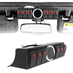
4. Installing the Switch Panel in the Lower Dash
3.1 select the appropriate legends from the switch legends sheet, and affix them to the panel. Center each
legend inside the grey border of each switch. Should you need to remove a legend, we suggest you use a straight
pin and lift at a corner until you can grasp it with your fingers. DO NOT dig at the graphic overlay, as the membrane
could be damaged.
3.2 Remove the 2 dash panels. Pry the trim edge with the trim removal tool then pull the upper panel out
loosening a screw to allow you remove the lower dash panel with trim removal tool.
(See Figure 9-10)
3.3 Remove the factory storage box, install the small cubby and switch panel. Note: Don’t need to install the
small cubby on a Jeep JL Rubicon.(See Figure 11)
3.4 Feed the control wire to the low dash along the trim gap. hide the wire behind the trim. connect wire to
switch panel.(See Figure 12)
3.5 Install the 2 factory dash panels back.
Figure 6
Figure 7
Figure 8
Figure 10
Figure 11Figure 12
Remove the storage box
Connect the accessory directly to the output sockets of the power module . The power module is waterproof and
dustproof . Lake down the waterproof plug , to run positive wire of
accessory to the inside through the hole , crimp the Y-shape terminal ( supplied) on the end of the wire, loosen the
Philips screw on the socket to allow the terminal to slide in, tighten the screw until the terminal is sung , screw the
lock nut to lock the wire to prevent water in. Do not over tighten it. (See Figure 13)
The JL300 switches 12V to the accessory . Connect the power module output wire to the positive wire of the
accessory. Connect the ground wire of the accessory directly to ground, either a ground stud on the vehicle’s
frame or to the negative terminal of the battery.
oosen the lock nut of the cable glands to t
Figure 13
1
2
3
4
5
6
Default(Ignition control disabled)
Ignition control is enabled
Install the trigger wire to enable the ignition control
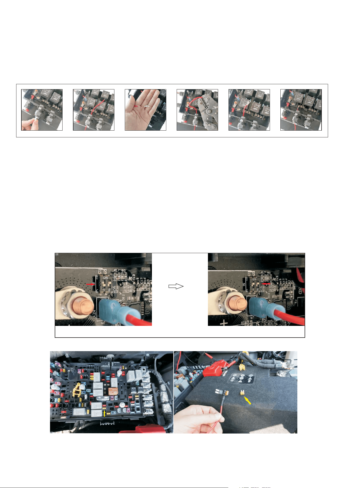
Toggle the dip switch 2 to ON position,( See Figure 14) .Connect the trigger wire to ACC power or a Keyed wire/fuse
to allow the control system only works when the vehicle is on. In general, ACC or CIGAR LTR fuse is better for use.
locate the fuse F52 that is for CIGAR LTR in factory fuse box . using the supplied piggyback fuse holder to connect
to your factory fuse panel. Remove the fuse M6 from the panel and place it into the lower slot of the piggyback fuse
holder then plug it into the slot you removed the factory fuse from. of course , you can select other fuse to tap.
for example, if you want the switch panel to work when the headlights light up, you can select the fuse for
headlights to tap. Note: Don't Forget to place the factory fuse you select for tapping in the lower slot of the
piggyback fuse holder.(See Figure 15-16)
7.Installing the trigger wire( If needed)
Installing the trigger wire to a keyed fuse or wire .The control system will be controlled by ignition. The switch panel
will turn off when ignition is off.
Default and factory setting is trigger control disabled and LVCO enabled , Dip switch 1 is for Low Voltage Cut Off
and the dip switch 2 is for trigger control .at default setting the accessories hooked can be turned on no matter your
vehicle is on or off ,you need to press the on/off switch to turn the switch panel off.
4
Figure 14
Figure 15
Factory Fuse F52
Fuse F52
Note : Accidentally an accessory that is left on will drain the battery overnight if the Low Voltage Cut Off is
disabled .
Figure 16
Figure 17
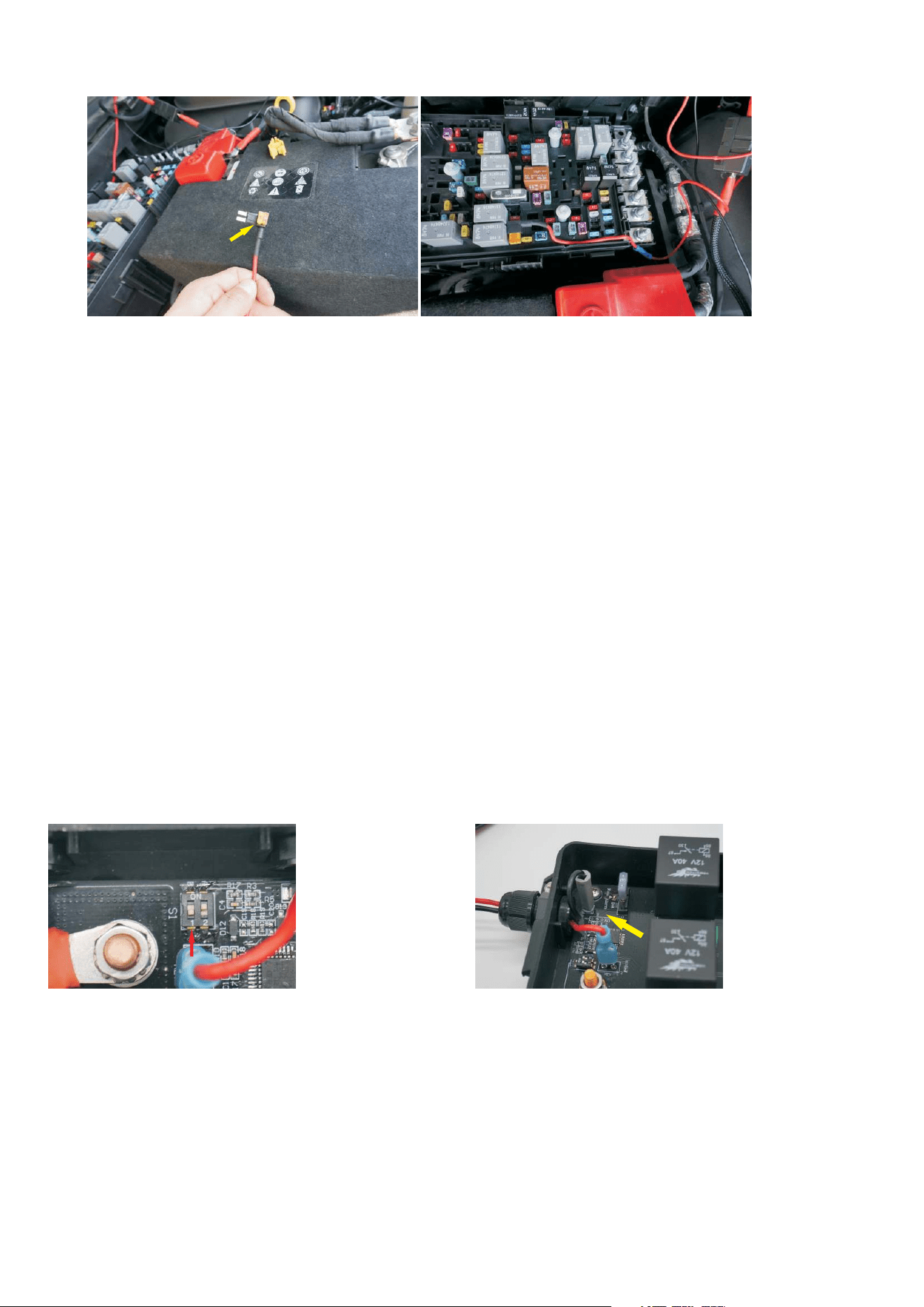
9.How to disable the Low Voltage Cut Off function ( if dual batteries installed)
Toggle the dip switch 1 to off position next to the label “1"( default is LVCO Enabled ) .(See Figure 17)
10.How to reset the system
Plug off the negative terminal then plug it in. the system will be reset .(See Figure 18)
Install fuse F52 into the lower
slot of the fuse tap
Plug fuse tap in the slot you
remove the F52 from
11.Maintain the Power Module
It is always good practice to have backup relay and fuse if you need to replace them. fuse and relay are
universal and standard. You can find in any auto parts store or online.
Figure 18
8.Programming your JL300
Programming the JL300 through the switch panel. there are 3 different programmable features for each button.
1.ON/OFF 2.Momentary 3.Flash 4.Strobe (
)
How to set the switch function
Ensure the switch panel is turned on. Press and hold the on/off switch for 3 seconds to activate programming
mode. select a switch to set, Each click of switch will scroll through functions. (Default for all switches is Steady
on) the amber indicator of the switch will show the function you select,
Note: Function 3 and 4 have double function. Single Press turns
on solid and double press will do flash or strobe.
The amber indicator LED will flash to
the appropriate function each time you click the switch through the 4 functions. Especially the indicator
only flashes once to show the Momentary function. To save your selected functions when complete, press
the On/Off Switch and hold on for 3 seconds to exit Programming Mode and your setting is saved.
if one switch
is set to flash or strobe, single Press turns on solid and double press will do flash or strobe.
5

fuse alarm light
Figure 19
www.voswitch.com
Scenario 2.switch panel doesn’t light up with ignition control wire installed to Fuse F52
please check the fuse tap, ensure factory fuse F52 is installed on the fuse tap(See Figure 16)
.
Scenario 3. switch panel will turn on with ignition control wire installed to Fuse F52 when the
engine is off. please check the DIP switch 2, the switch 2 should be at the on position.
Scenario 4.the switch panel won’t turn on with everything are intact, please test the 4 pin control
wire continuity.
Scenario 5. switch panel always flashes and doesn’t work. it says the battery voltage is less than
11.3V. please charge your battery to have a try.
if you can’t shoot the trouble ,please contact the manufacturer at the website below.
12.Trouble Shooting
Scenario 1. if switch panel doesn’t light up, please check the fuse alarm light (See Figure 16).
you need to replace the 3amp fuse if the alarm light lights up.
6