Product Name and Model Number User Manual
Page | 1 Copyright©2026 ZKTECO CO., LTD. All rights reserved.
User Manual
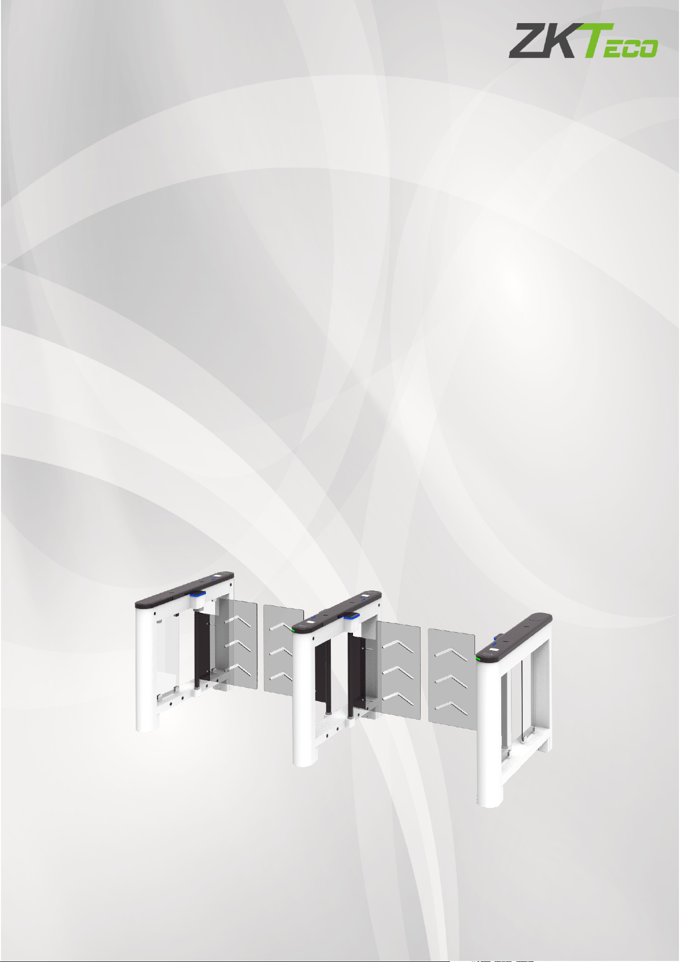
Saturn-S1000 Pro Series
Applicable Model(s): Saturn-S1000 Pro, Saturn-S1200 Pro
Date: July 2026
Doc Version: 1.0
English

Saturn-S1000 Pro Series User Manual
Page | 2 Copyright©2026 ZKTECO CO., LTD. All Rights Reserved.
Copyright © 2026 ZKTECO CO., LTD. All rights reserved.
Without the prior written consent of ZKTeco, no portion of this manual can be copied or forwarded in any
way or form. All parts of this manual belong to ZKTeco and its subsidiaries (hereinafter the "Company" or
"ZKTeco").
Trademark
is a registered trademark of ZKTeco. Other trademarks involved in this manual are owned by
their respective owners.
Disclaimer
This manual contains information on the operation and maintenance of the ZKTeco equipment. The
copyright in all the documents, drawings, etc. in relation to the ZKTeco supplied equipment vests in and is
the property of ZKTeco. The contents hereof should not be used or shared by the receiver with any third
party without express written permission of ZKTeco.
The contents of this manual must be read as a whole before starting the operation and maintenance of the
supplied equipment. If any of the content(s) of the manual seems unclear or incomplete, please contact
ZKTeco before starting the operation and maintenance of the said equipment.
It is an essential pre-requisite for the satisfactory operation and maintenance that the operating and
maintenance personnel are fully familiar with the design and that the said personnel have received
thorough training in operating and maintaining the machine/unit/equipment. It is further essential for the
safe operation of the machine/unit/equipment that personnel has read, understood and followed the
safety instructions contained in the manual.
In case of any conflict between terms and conditions of this manual and the contract specifications,
drawings, instruction sheets or any other contract-related documents, the contract conditions/documents
shall prevail. The contract specific conditions/documents shall apply in priority.
ZKTeco offers no warranty, guarantee or representation regarding the completeness of any information
contained in this manual or any of the amendments made thereto. ZKTeco does not extend the warranty
of any kind, including, without limitation, any warranty of design, merchantability or fitness for a particular
purpose.
ZKTeco does not assume responsibility for any errors or omissions in the information or documents which
are referenced by or linked to this manual. The entire risk as to the results and performance obtained from
using the information is assumed by the user.
ZKTeco in no event shall be liable to the user or any third party for any incidental, consequential, indirect,
special, or exemplary damages, including, without limitation, loss of business, loss of profits, business
interruption, loss of business information or any pecuniary loss, arising out of, in connection with, or

Saturn-S1000 Pro Series User Manual
Page | 3 Copyright©2026 ZKTECO CO., LTD. All Rights Reserved.
relating to the use of the information contained in or referenced by this manual, even if ZKTeco has been
advised of the possibility of such damages.
This manual and the information contained therein may include technical, other inaccuracies or
typographical errors. ZKTeco periodically changes the information herein which will be incorporated into
new additions/amendments to the manual. ZKTeco reserves the right to add, delete, amend or modify the
information contained in the manual from time to time in the form of circulars, letters, notes, etc. for better
operation and safety of the machine/unit/equipment. The said additions or amendments are meant for
improvement /better operations of the machine/unit/equipment and such amendments shall not give any
right to claim any compensation or damages under any circumstances.
ZKTeco shall in no way be responsible (I) in case the machine/unit/equipment malfunctions due to any
non-compliance of the instructions contained in this manual (ii) in case of operation of the
machine/unit/equipment beyond the rate limits (iii) in case of operation of the machine and equipment in
conditions different from the prescribed conditions of the manual.
The product will be updated from time to time without prior notice. The latest operation procedures and
relevant documents are available on http://www.zkteco.com
If there is any issue related to the product, please contact us.
ZKTeco Headquarters
Address ZKTeco Industrial Park, No. 32, Industrial Road,
Tangxia Town, Dongguan, China.
Phone +86 769 - 82109991
Fax +86 755 - 89602394
For business-related queries, please write to us at: [email protected]m.
To know more about our global branches, visit www.zkteco.com.

Saturn-S1000 Pro Series User Manual
Page | 4 Copyright©2026 ZKTECO CO., LTD. All Rights Reserved.
About the Company
ZKTeco is one of the world’s largest manufacturer of RFID and Biometric (Fingerprint, Facial, Finger-vein)
readers. Product offerings include Access Control readers and panels, Near & Far-range Facial Recognition
Cameras, Elevator/floor access controllers, Turnstiles, License Plate Recognition (LPR) gate controllers and
Consumer products including battery-operated fingerprint and face-reader Door Locks. Our security
solutions are multi-lingual and localized in over 18 different languages. At the ZKTeco state-of-the-art
700,000 square foot ISO9001-certified manufacturing facility, we control manufacturing, product design,
component assembly, and logistics/shipping, all under one roof.
The founders of ZKTeco have been determined for independent research and development of biometric
verification procedures and the productization of biometric verification SDK, which was initially widely
applied in PC security and identity authentication fields. With the continuous enhancement of the
development and plenty of market applications, the team has gradually constructed an identity
authentication ecosystem and smart security ecosystem, which are based on biometric verification
techniques. With years of experience in the industrialization of biometric verifications, ZKTeco was
officially established in 2007 and now has been one of the globally leading enterprises in the biometric
verification industry owning various patents and being selected as the National High-tech Enterprise for 6
consecutive years. Its products are protected by intellectual property rights.
About the Manual
This manual introduces the operations of Saturn-S1000 Pro Series.
All figures displayed are for illustration purposes only. Figures in this manual may not be exactly consistent
with the actual products.
Features and parameters with ★ are not available in all devices.
Saturn-S1000 Pro Series User Manual
Page | 5 Copyright©2026 ZKTECO CO., LTD. All Rights Reserved.
Safety Instruction
These instructions are intended to ensure that user can use the product correctly to avoid danger or
property loss.
The precaution measure is divided into Dangers and Cautions:
Dangers: Neglecting any of the warnings may cause serious injury or death.
Cautions: Neglecting any of the cautions may cause injury or equipment damage.
Symbols
Convention Description
Dangers: Follow these safeguards to prevent serious injury or death.
Cautions: Follow these precautions to prevent potential injury or material damage.
Dangers:
In the use of the product, you must be in strict compliance with the electrical safety regulations of the
nation and region.
The equipment must be connected to an earthed mains socket-outlet.
Shock hazard! Disconnect all power sources before maintenance.
Do not touch the bare metal contacts of the inlets after the circuit breaker is turned off. Electricity still
exists.
To prevent possible hearing damage, do not listen at high volume levels for long periods.
All the electronic operation should be strictly compliance with the electrical safety regulations, fire
prevention regulations and other related regulations in your local region.
Please use the power adapter, which is provided by normal company. The power consumption cannot
be less than the required value.
Do not connect several devices to one power adapter as adapter overload may cause over-heat or fire
hazard.
Please make sure that the power has been disconnected before you wire, install or dismantle the
device.
If the top caps should be open and the device should be powered on for maintenance, make sure:
1. Power off the fan to prevent the operator from getting injured accidentally.
2. Do not touch bare high-voltage components.
3. Make sure the switch's wiring sequence is correct after maintenance.
Please make sure that the power has been disconnected before you wire, install or dismantle the

Saturn-S1000 Pro Series User Manual
Page | 6 Copyright©2026 ZKTECO CO., LTD. All Rights Reserved.
device.
If smoke, odors or noise rise from the device, turn off the power at once and unplug the power cable,
and then please contact the service center.
If the product does not work properly, please contact your dealer or the nearest service center. Never
attempt to disassemble the device yourself. (We shall not assume any responsibility for problems
caused by unauthorized repair or maintenance.)
The Terminal PE of the switch should be connected to a ground wire.
Cautions:
Instructions must be read before installation. Please follow these instructions carefully, incorrect
installation could affect gate operation.
When mounting and positioning this product please ensure the power cable is unplugged.
The motor cover will need to be removed to mount the motor to the mounting plate. Electrical-related
operation of the main unit can only be made by a licensed electrician.
To prevent injury, this equipment must be securely attached to the floor/base of the turnstile in
accordance with the installation instructions.
Keep straight down when moving or using the equipment.
Never place the equipment in an unstable location. The equipment may fall, causing serious personal
injury or death.
Cold-rolled SPCC steel may be corroded in some circumstances. You need to clean and care the device
by using the stainless steel cleaner. It is suggested to clean the device every month.
Do not drop the device or subject it to physical shock, and do not expose it to high electromagnetism
radiation. Avoid the equipment installation on vibrations surface or places subject to shock (ignorance
can cause equipment damage).
Do not place the device in extremely hot (refer to the specification of the device for the detailed
operating temperature), cold, dusty or damp locations, and do not expose it to high electromagnetic
radiation.
The device cover for indoor use shall be kept from rain and moisture.
Exposing the equipment to direct sun light, low ventilation or heat source such as heater or radiator is
forbidden (ignorance can cause fire danger).
Do not aim the device at the sun or extra bright places. A blooming or smear may occur otherwise
(which is not a malfunction however), and affecting the endurance of sensor at the same time.
Please use the provided glove when open up the device cover, avoid direct contact with the device
cover, because the acidic sweat of the fingers may erode the surface coating of the device cover.
Please use a soft and dry cloth when clean inside and outside surfaces of the device cover, do not use
alkaline detergents.
Please keep all wrappers after unpack them for future use. In case of any failure occurred, you need to

Saturn-S1000 Pro Series User Manual
Page | 7 Copyright©2026 ZKTECO CO., LTD. All Rights Reserved.
return the device to the factory with the original wrapper. Transportation without the original wrapper
may result in damage on the device and lead to additional costs.
Improper use or replacement of the battery may result in hazard of explosion. Replace with the same
or equivalent type only. Dispose of used batteries according to the instructions provided by the
battery manufacturer.
Biometric authentication products are not 100% applicable to anti-spoofing environments. If you
require a higher security level, use multiple authentication modes.
Do not stay in the lane when the device is rebooting.
RISK OF EXPLOSION IF BATTERY IS REPLACED BY AN INCORRECT TYPE. DISPOSE OF USED BATTERIES
ACCORDING TO THE INSTRUCTIONS.
SUITABLE FOR MOUNTING ON CONCRETE OR OTHER NON-COMBUSTIBLE SURFACE ONLY.
The instructions shall require connection of the equipment protective earthing conductor to the
installation protective earthing conductor.

Saturn-S1000 Pro Series User Manual
Page | 8 Copyright©2026 ZKTECO CO., LTD. All Rights Reserved.
Table of Contents
1 OVERVIEW .......................................................................................................................................... 10
Key Features .............................................................................................................................................................................................. 11
Specification ............................................................................................................................................................................................. 12
1.2.1 Appearance ................................................................................................................................................................................................... 12
1.2.2 System Components .................................................................................................................................................................................. 15
1.2.3 Specifications ................................................................................................................................................................................................ 17
Mechanical System ................................................................................................................................................................................. 19
Electronic Control System ................................................................................................................................................................... 19
2 AUTHENTICATION METHODS ........................................................................................................... 21
Card Verification★ ................................................................................................................................................................................. 22
QR Code Verification★ ......................................................................................................................................................................... 22
Facial Authentication★ ....................................................................................................................................................................... 23
3 INSTALLATION ................................................................................................................................... 24
Installation Tools ..................................................................................................................................................................................... 24
Installation Requirements ................................................................................................................................................................... 24
Installation Environment ..................................................................................................................................................................... 24
Installation Cabinet ................................................................................................................................................................................ 25
Accessory Installation ............................................................................................................................................................................ 31
3.5.1 Facial Authentication Terminal Installation ........................................................................................................................................ 31
3.5.2 Swing Barrier Installation .......................................................................................................................................................................... 32
4 TERMINAL DESCRIPTION .................................................................................................................. 33
Main and Sub Board ............................................................................................................................................................................... 33
IR Sensor Board ........................................................................................................................................................................................ 34
5 WIRING INSTRUCTIONS ..................................................................................................................... 35
Main-Sub Location ................................................................................................................................................................................. 35
Slotting Position ...................................................................................................................................................................................... 36
Wiring Methods ....................................................................................................................................................................................... 36
Main and Sub Connection Cable ...................................................................................................................................................... 37
Power and Air Switch Wiring .............................................................................................................................................................. 37
System Wiring Diagram ........................................................................................................................................................................ 38
6 OPERATION PROCESS ....................................................................................................................... 39
7 MACHINE OPERATION ....................................................................................................................... 41
Operation Buttons Description ......................................................................................................................................................... 41
Menu Parameter Settings .................................................................................................................................................................... 41

Saturn-S1000 Pro Series User Manual
Page | 9 Copyright©2026 ZKTECO CO., LTD. All Rights Reserved.
8 MAINTENANCE .................................................................................................................................. 51
Chassis Maintenance ............................................................................................................................................................................. 51
Movement Maintenance ...................................................................................................................................................................... 51
Power Supply Maintenance ................................................................................................................................................................ 51
9 TROUBLESHOOTING.......................................................................................................................... 52
10 PACKING LIST ................................................................................................................................. 53
Saturn-S1000 Pro Series User Manual
Page | 10 Copyright©2026 ZKTECO CO., LTD. All Rights Reserved.
1 Overview
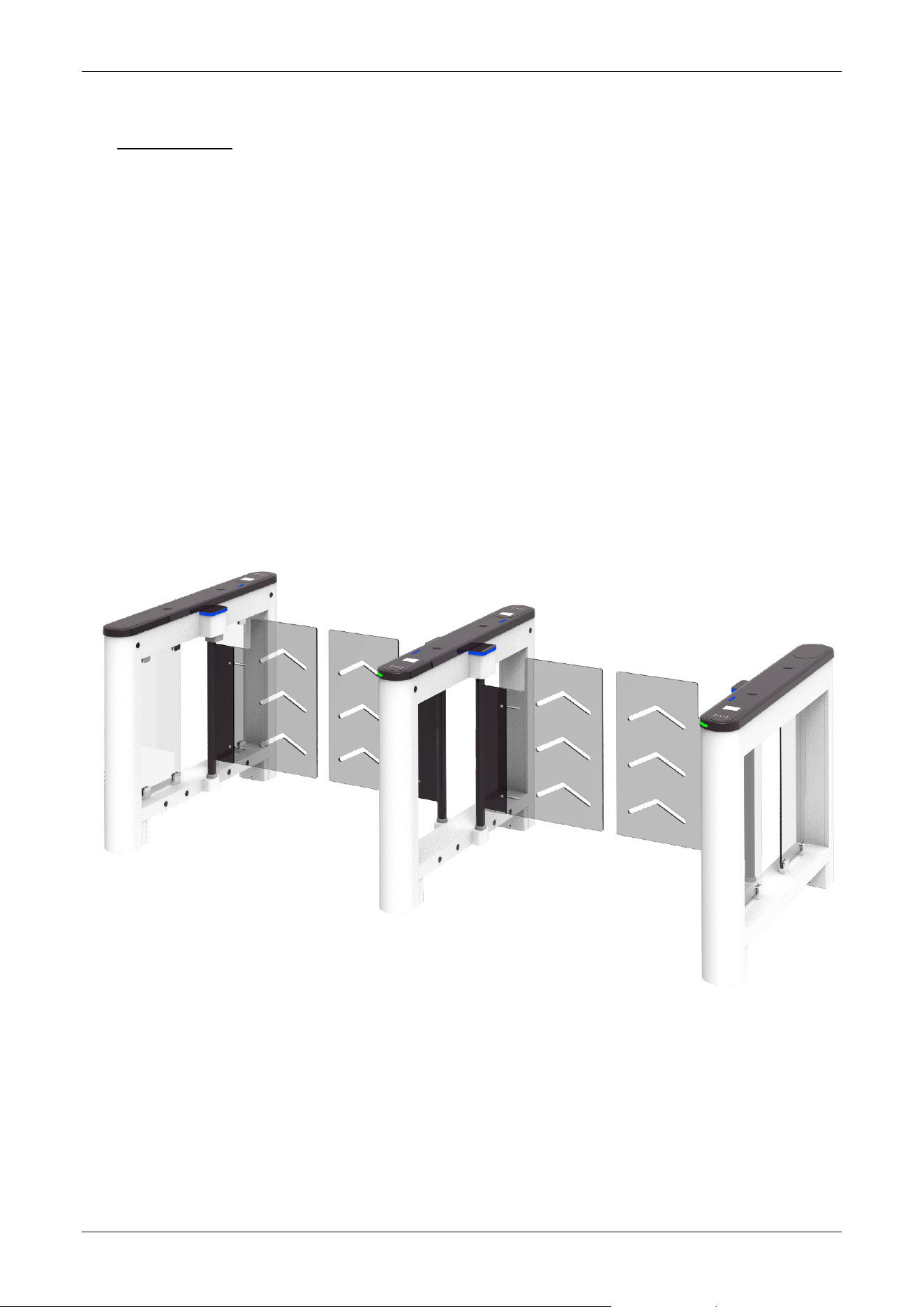
Unveiling the ZKTeco Saturn Pro Series, an innovative swing barrier turnstile designed for a paralleled
passage experience. With its sophisticated design, the Saturn Pro Series is available in range of striking
colors including Pearl White (PWH), Space Gray (SGY), Carbon Black (CBK), Bay Blue (BBLE) and Mist Brown
(MBW), making it blends seamlessly with both indoor and outdoor applications.
Crafted from cold-rolled SPCC steel (GB700) the chassis features an integrated cover molding process and
boasts an IPX4 protection rating, ensuring exceptional resistance to water and dust. The authentication
area is enhanced with 2.5D tempered glass, offering superior scratch and wear resistance. The Saturn Pro
Series accommodates various credential options, including single lane and dual swing configurations, with
support for facial authentication, QR codes, and multi-tech cards.
Additionally, it features 6 pairs of infrared sensors for dual pinch protection, enhancing safety with locked
positions and automatic barrier opening during emergencies.

Saturn-S1000 Pro Series User Manual
Page | 11 Copyright©2026 ZKTECO CO., LTD. All Rights Reserved.
Key Features
Innovative Aesthetics
The Saturn Pro series is available in an array of contemporary colors, including Pearl White, Space Gray, Bay
Blue, Mist Brown and Carbon black.
Durability
The lid is made using an integrated molding process, achieves an IPX4 protection rating, offering robust
defense against water and dust. The product is designed to thrive in extreme conditions, maintaining
functionality after an 8-hour period in sub-zero temperatures as low as -30°C.
Material Innovation
The outer surface is treated with electrostatic spraying, which ensures excellent adhesion and prevents
paint from dripping. This treatment also aids in thermal regulation, preventing surface burns due to high
temperatures. The identification area is elegantly embedded with 2.5D tempered glass, which is
resistant to scratches and wear, enhancing the clarity of the identification process.
DC Brushless Motor
The Saturn Pro Series uses DC brushless motors, which are stable and reliable, and the movement life
reaches 5 million MCBF. Barrier material made of acrylic, the default lane width is 650mm. The default lane
width is 650 mm; optional widths of 1000 mm (acrylic) and 1200 mm (SUS304) are available. This modular
design is convenient for maintenance and lower operating costs.
Safety and Security
Safety features include a swing arm with the upper edge is more than 800mm from the ground and the
lower edge is less than 200mm, effectively preventing unauthorized crossings. Additionally, the Saturn Pro
series is fortified with 6 pairs of infrared sensors for double anti-crushing protection and a leakage protection
switch to protect against electrical hazards.
Saturn-S1000 Pro Series User Manual
Page | 12 Copyright©2026 ZKTECO CO., LTD. All Rights Reserved.
Specification
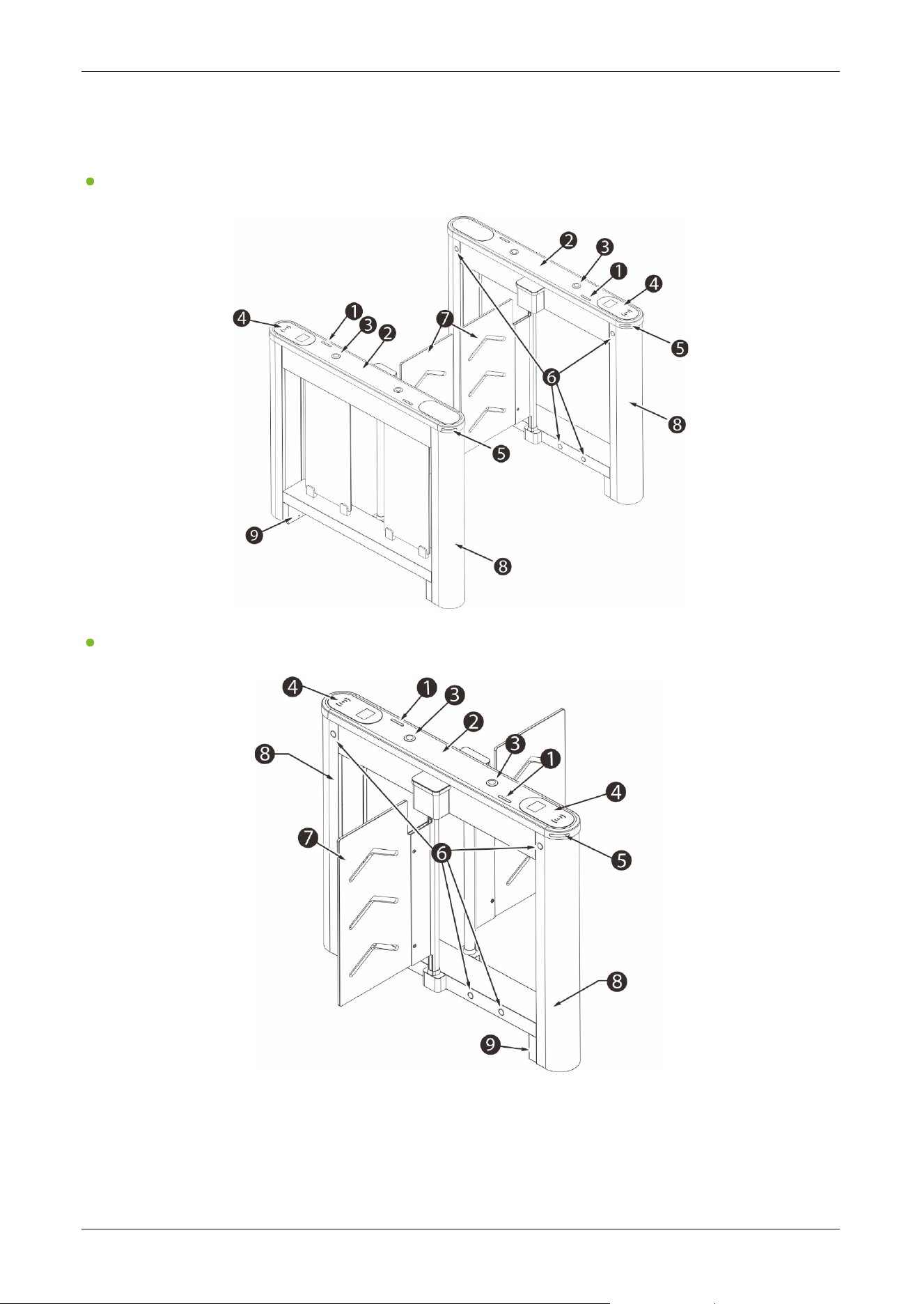
1.2.1 Appearance
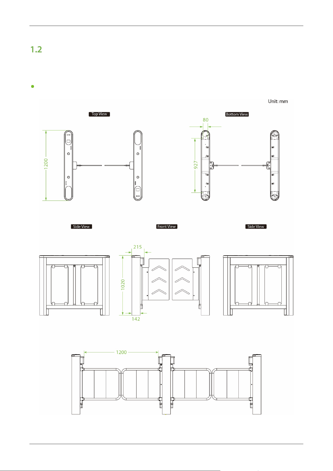
Saturn-S1000 Pro:
Saturn-S1000 Pro Series User Manual
Page | 13 Copyright©2026 ZKTECO CO., LTD. All Rights Reserved.
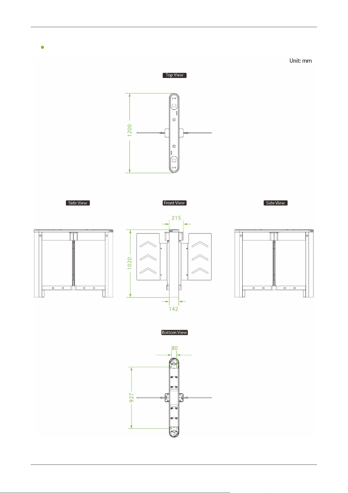
Saturn-S1200 Pro:
Saturn-S1000 Pro Series User Manual
Page | 14 Copyright©2026 ZKTECO CO., LTD. All Rights Reserved.
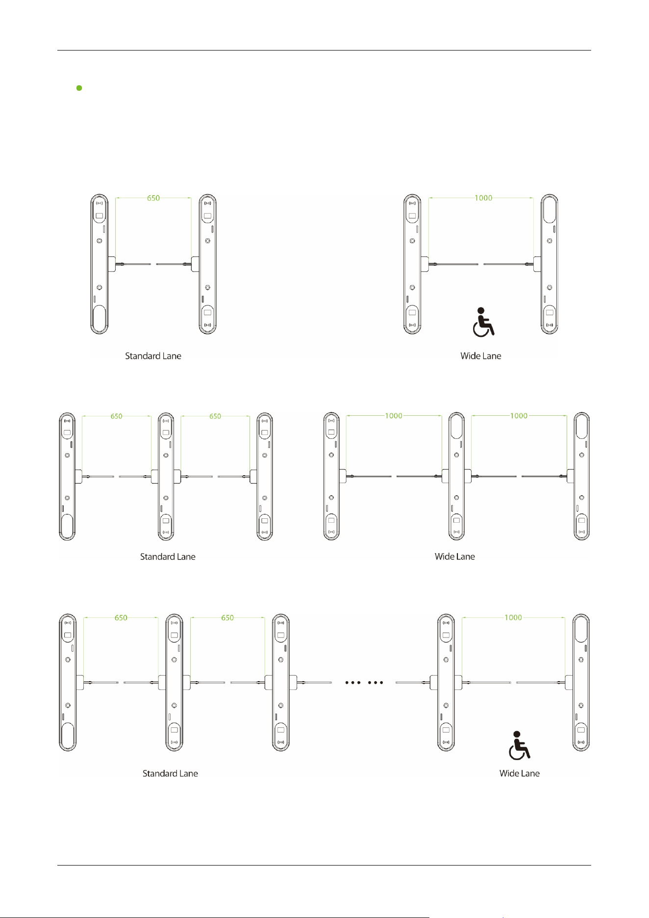
Swing Barriers Specifications
The Saturn-S1000 Pro and Saturn-S1200 Pro can be combined to form a single, dual or multi-lane
system, allowing the user to select the appropriate swing barrier size according to actual needs.
1) Single-lane
2) Dual-lane
3) Multi-lane
Saturn-S1000 Pro Series User Manual
Page | 15 Copyright©2026 ZKTECO CO., LTD. All Rights Reserved.
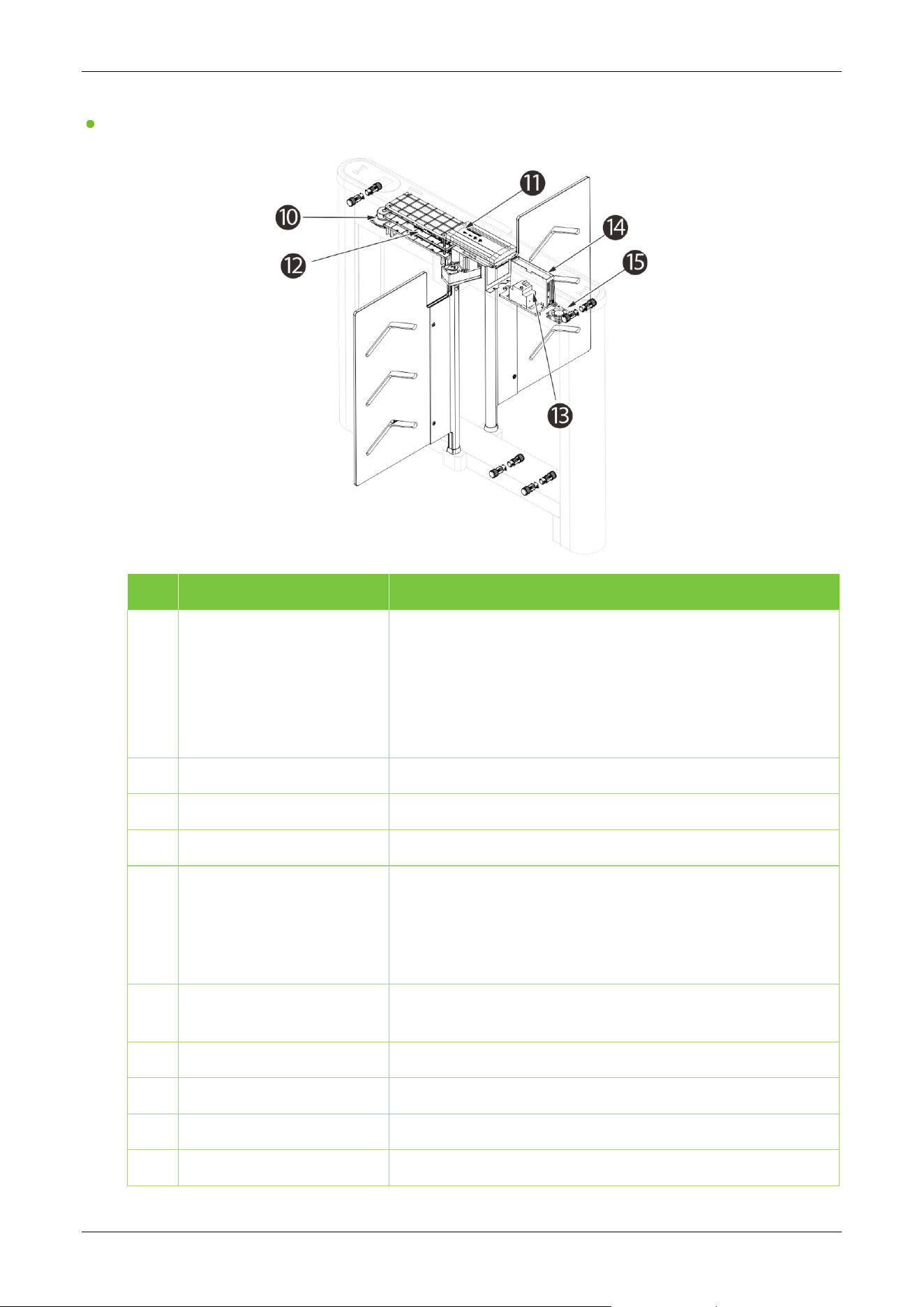
1.2.2 System Components
Saturn-S1000 Pro:
Saturn-S1200 Pro:
Saturn-S1000 Pro Series User Manual
Page | 16 Copyright©2026 ZKTECO CO., LTD. All Rights Reserved.
Core Component
No. Components Descriptions
1 Visual Indicator
Top LED indicator:
Blue=Door closed /stand by
Green=Door opening
Red=Door closing/alarm
To indicate the passage status
2 Top Lid Polycarbonate+2.5D Tempered glass
3 Reserve Mounting Holes Reserved mounting holes for facial authentication devices.
4 Verification Area Card (RFID)/Facial/QR Code modules are available
5 Entry/Exit Visual Indicator
Slide LED indicator:
Green=Lane available
Red=Lane unavailable
Used to indicate the Entry/Exit passage status
6 Infrared Sensor
It detects the position of the pedestrian and plays a role in
ensuring safety and protection
7 Barrier Material Clear Acrylic(optional: Tempered Glass)
8 Side Lids Polycarbonate
9 Expansion Screw Cover Plate Used to cover expansion screws.
10
Speaker To play alarms and alert voices.

Saturn-S1000 Pro Series User Manual
Page | 17 Copyright©2026 ZKTECO CO., LTD. All Rights Reserved.
11
Access controller
To verify if the credential is valid. If successful, sends a door open signal
to the turnstile controller. Otherwise will not.
12 Turnstile Controller Board The system’s control center
13 Air Switch
It provides reliable protection by automatically disconnecting the circuit
in the event of overload, short circuit, under voltage, or power loss.
14
Power Supply
110V / 220V ±10% AC @50Hz/ 60Hz
15 Fan Used for cooling.
1.2.3 Specifications
Model Saturn-S1000 Pro Saturn-S1200 Pro
Audio Indicator
Internal speaker
Visual Indicator
Top LED indicator:
Blue=Door closed /stand by
Green=Door opening
Red=Door closing/alarm
Slide LED indicator:
Green=Lane available
Red=Lane unavailable
Display
NA
Lane Type
Single Lane Dual Swings(with Saturn-S1200 Pro)
Lane Width
600~750mm(Standard; acrylic barrier; adjustable)
1000mm (Optional; acrylic barrier)
1200mm (Optional; SUS304 barrier)
Barrier Movement Type
Swing
Motor
DC brushless motor
Movement Speed
Average 1s per movement (Adjustable open/close timing)
Movement Accuracy
NA
Clutch
NA
Lid Material
Polycarbonate+2.5D tempered glass
Lid Options
Authentication
Methods
Streamlined under mount options: QR Code / RFID
Surface mount option: Facial Authentication
Chassis Material
Cold-rolled SPCC Steel (GB700) / Polycarbonate (Side Lid)
Chassis Colour
Pearl White(PWH), Space Gray(SGY), Carbon Black(CBK), Bay Blue(BBLE), Mist
Brown(MBW)
Barrier Material
Clear acrylic (635*300mm)(standard)
(For extended lane width of 1200mm requires SUS304 barrier)
IR Sensors
6 pairs (standard) ; 8 pairs (optional)

Saturn-S1000 Pro Series User Manual
Page | 18 Copyright©2026 ZKTECO CO., LTD. All Rights Reserved.
Motherboard Function
System configuration, access control
Motherboard
Communication
Fire alarm Port (Relay)*1, RS485 Port*1
Controller
Not equipped.
Compatible with C3 series controller/ InBio series controller (optional)
Credential Options
Under mount RFID reader: Pro ID Series, KR Series
Under mount QR code reader: QR500
Surface mount facial authentication reader: ProFace X / SpeedFace V5L
Flow Rate
Facial Authentication: 15 passengers per minute
QR Code: 30 passengers per minute
RFID: 35 passengers per minute
Accessibility
Adult, children (with care), Disability (with care)
Power Supply
110V/220V±10% AC @50Hz/60Hz
Power Rating
10VA (Standby) 40VA (Operation)
Fire Signal
Input for voltage free contact
Noise Level
Less than 50dB
MTTR
Less than 60 minutes
MCBF
5 million
Weight
Net weight (50kg) Net weight (30kg)
Dimension (L*W*H)
1200*150*1020mm
Dimensions With
Packing(L*W*H)
Carton (standard): 1265*220*1070
mm (2 boxes)
Wooden box (optional):
1300*480*1224 (2 box)
Carton (standard): 1346*720*1082mm
(2box)/1346*360*1082mm
Wooden box (optional):
1300*630*1222mm(2box)/
1300*315*1222mm
Operating Temperature
-30℃ to 70℃
Operating Humidity
5% to 90% RH (Non-condensing)
Certifications
CE, FCC
Ingress Protection
Rating
IPX4
Supported Software
ZKBio CVAccess / ZKBio CVSecurity (Depends on equipped access controller)
Safety Features
Power off unlock device/ Fire alarm active door release
Security Features
Anti-tailgating, anti-pinch
Product Delivery
Pre-assembled for easy installation
Application
Environment
Indoor/outdoor (if sheltered)
Site Preparation
Flat and level finished floor (optional base plate for unfinished floors)
Security Level
Middle
Emergency Mode
Swing barrier unlocks automatically
Saturn-S1000 Pro Series User Manual
Page | 19 Copyright©2026 ZKTECO CO., LTD. All Rights Reserved.
Packing Material
Wooden Box
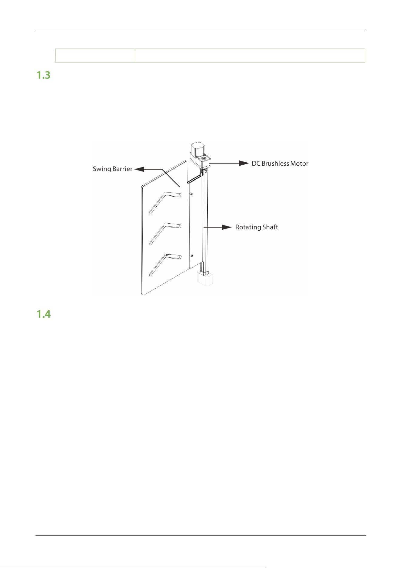
Mechanical System
The mechanical system of the turnstile includes the chassis and the core component.
Chassis: It is a carrier where the Visual Indicator and Infrared Sensor are installed.
Core Component: The core component mainly consists of the Frame, DC Brushless Motor,
Rotating Shaft and Swing Barrier.
Electronic Control System
The electronic control system of a turnstile is mainly composed of the Servo Motor Driver, Infrared
Sensor, Turnstile Control Board, Traffic Indicator and Alarm.
Power Supply: connected with AC power and converting to DC power for turnstile operating
system.
Access Control System: including various types of readers such as RFID readers, QR code
readers, and facial authentication devices, and access controllers.
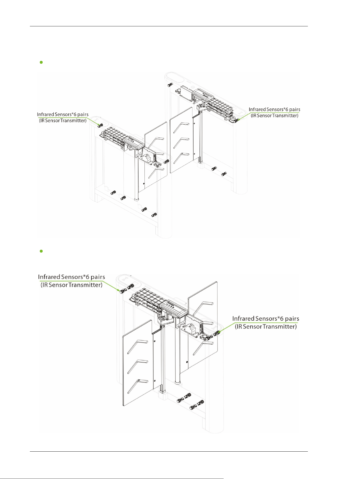
Infrared Sensor: It detects the position of the pedestrian and plays the role of safety protection.
Turnstile Control Board: The Turnstile control board is the system’s control center that receives
signals from the reader. The IR performs logical calculation and processing of these signals and
then sends executive commands to the Traffic Indicator, Electric Motor, and the alarm.
Traffic Indicator: The system will light up the red indicator when the gate is closed. When
someone passes the verification, the system will light up the green indicator.
Alarm: The alarm gives the voice and light alarm if the system detects any unauthorized entry
to the passage, false direction entry, anti-tailgate and other violations.
Saturn-S1000 Pro Series User Manual
Page | 20 Copyright©2026 ZKTECO CO., LTD. All Rights Reserved.
Saturn-S1000 Pro:
Saturn-S1200 Pro:
Saturn-S1000 Pro Series User Manual
Page | 21 Copyright©2026 ZKTECO CO., LTD. All Rights Reserved.
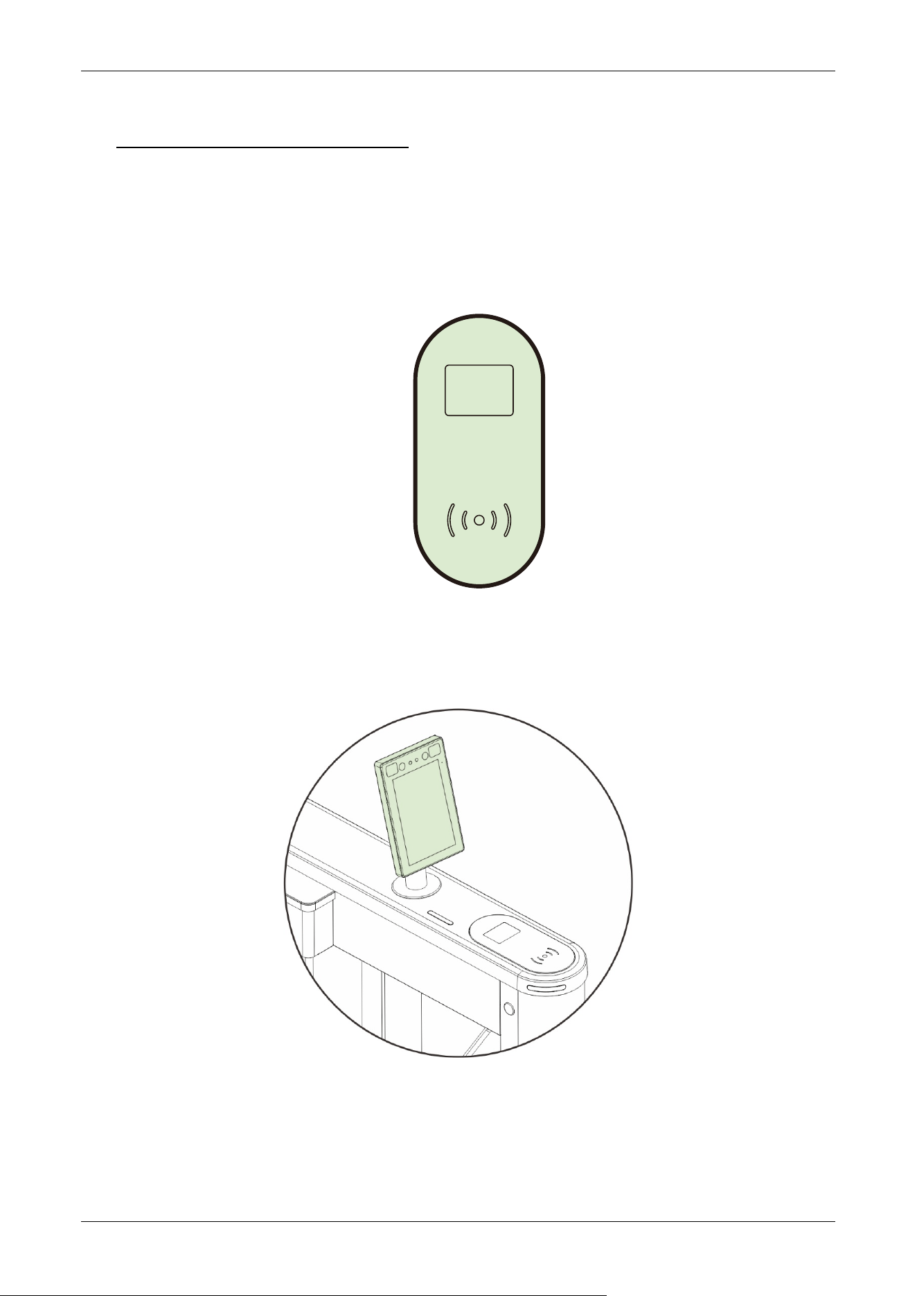
2 Authentication Methods
Users can freely choose to configure the authentication module according to actual needs. The
following options are included.
Streamlined Under Mount Options:
RFID only, RFID & QR Code.
Surface Mount Option:
Mounting Pole (Compatible with ProFace X series / SpeedFace V5L)
Saturn-S1000 Pro Series User Manual
Page | 22 Copyright©2026 ZKTECO CO., LTD. All Rights Reserved.
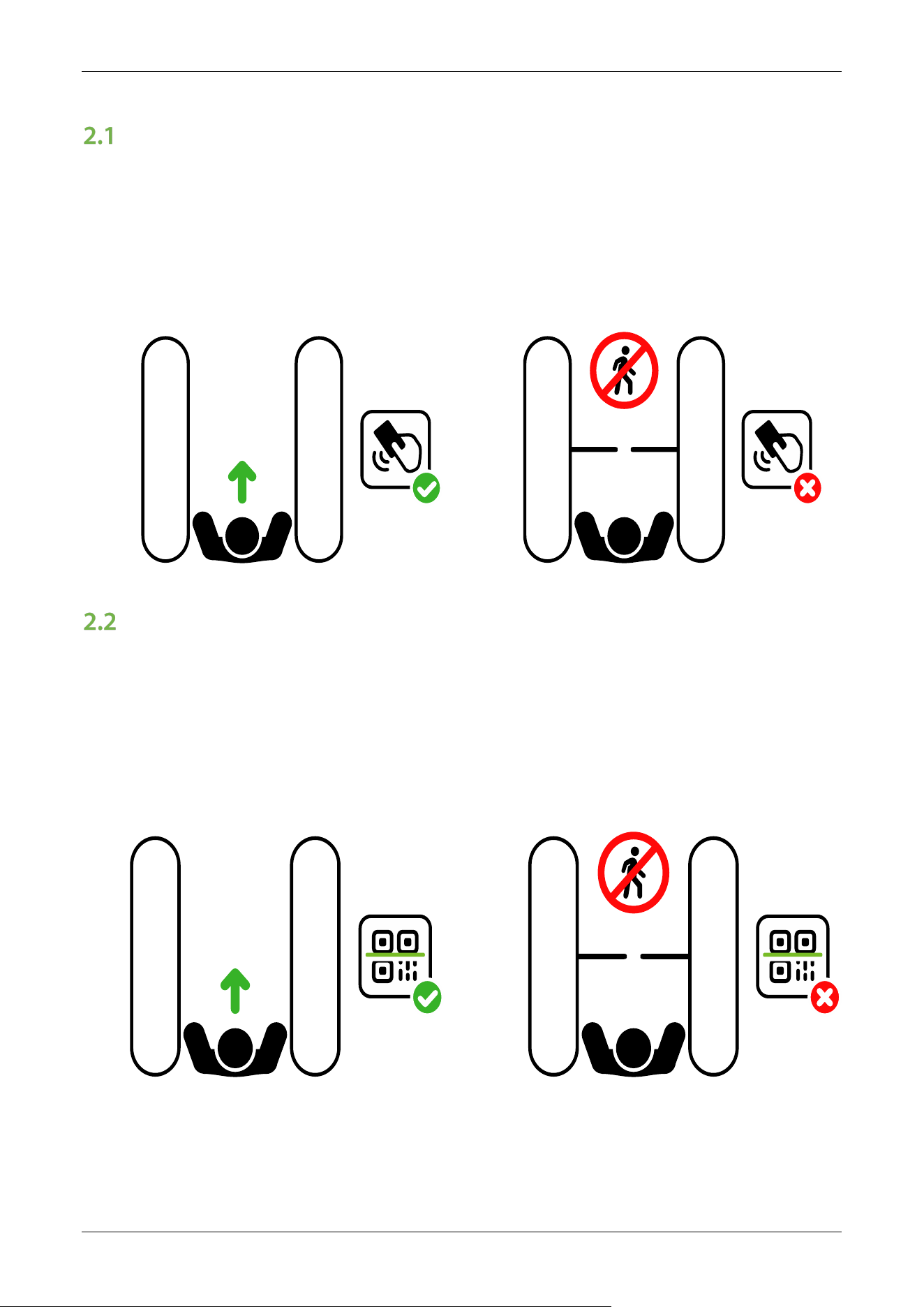
Card Verification★
When the device is configured with a card swipe module, the Card Verification mode compares the
card number in the card induction area with all of the card number data registered in the device and
sends it to the Access Controller.
When a user presses his / her card on the card reading area, the device enters card authentication
mode.
RFID
NO ENTRY
RFID
QR Code Verification★
The QR code Verification mode is to scan the QR code on the user's mobile phone through the QR
code scanner and compare the data with the registered QR code, and then sends it to the Access
Controller.
When the user places the mobile phone displaying with the QR code on top of the QR code scanner,
the device enters the QR code authentication mode.
RFID
NO ENTRY
RFID
Saturn-S1000 Pro Series User Manual
Page | 23 Copyright©2026 ZKTECO CO., LTD. All Rights Reserved.
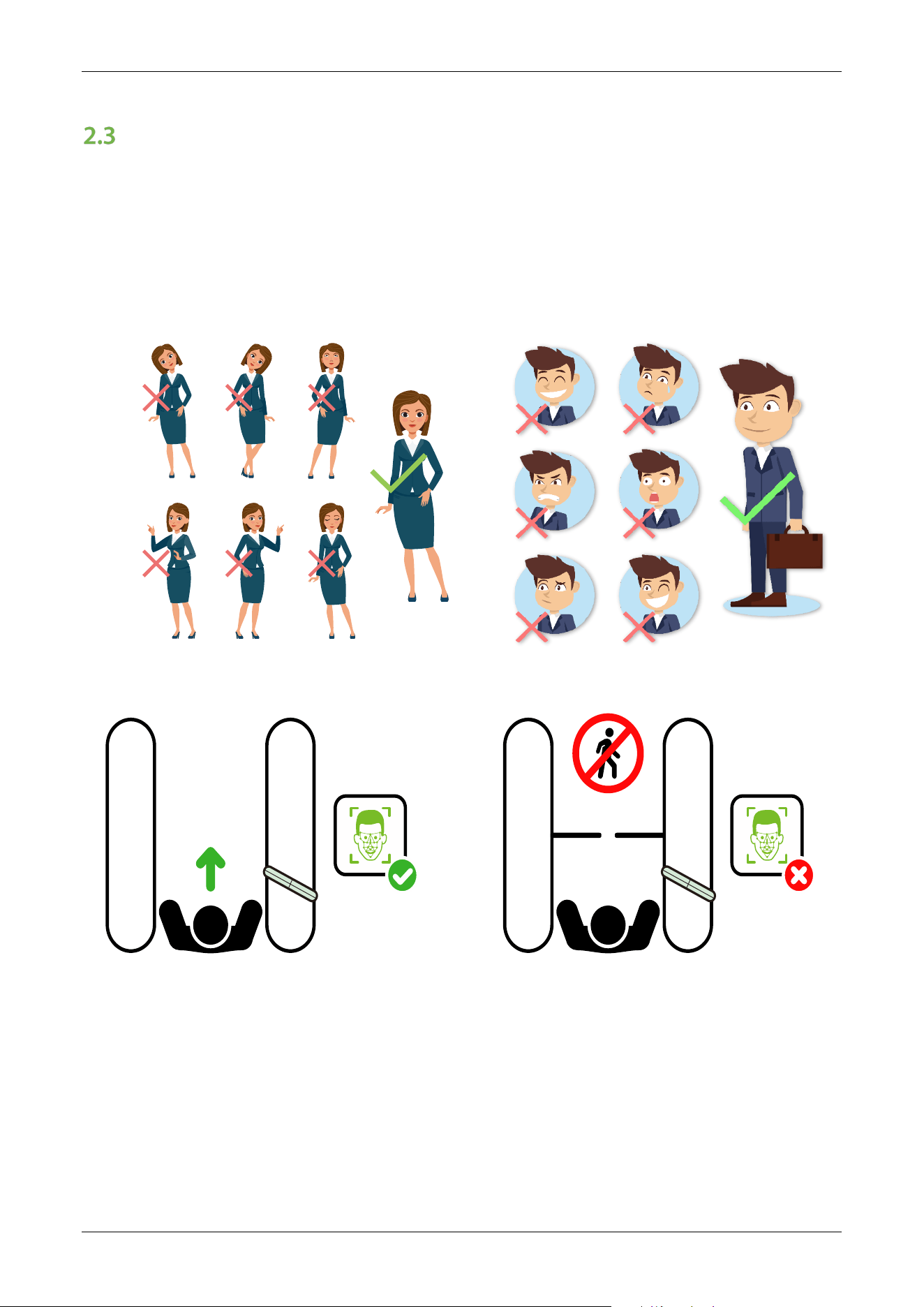
Facial Authentication★
In this verification mode, the device compares the collected facial images with all face data
registered in the device and then sends it to the Access Controller.
Try to keep the face in the centre of the screen during authentication. Please face towards the
camera and stay still during face registration.
Recommended Standing Posture and Facial Expression:
Note: Please keep your facial expression and standing posture natural while enrollment or verification.
RFID
NO ENTRY
RFID

Saturn-S1000 Pro Series User Manual
Page | 24 Copyright©2026 ZKTECO CO., LTD. All Rights Reserved.
3 Installation
Installation Tools
Tapeline
Marker Pen
Pencil
Percussion Drill
Screwdriver
Wrench
Hex Wrench
Cutting Machine
Installation Requirements
1. It is recommended that the turnstile must be installed on a horizontal solid platform with a height of
50mm to 100mm.
2. It is recommended that the turnstile should not be used in the corrosive environment.
3. Make sure that the ground wire of the system is securely connected to avoid personal injuries or
other accidents.
4. After installation, check if the connection has been done correctly at the connecting points of
the ground wire, at the connector assemblies and wiring points of the circuits, as well as at each
movable part of the turnstile. Any loose nuts, screws and other fasteners should be tightened in
time to avoid any failures caused by long-time operations.
Installation Environment
1. Before installation begins, prepare installation tools, check the device and the accessories, and
clear the installation base.
2. Make sure that the appliance is mounted on a concrete surface or other non-flammable surfaces.
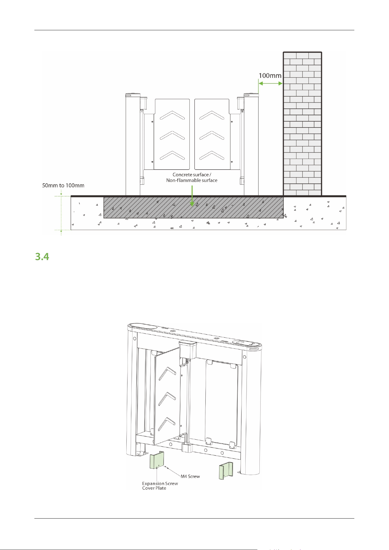
3. The installation position of the turnstile depends on its size. A distance of 100mm between the
turnstile and the wall needs to be reserved for ease of opening the top lid of the turnstile to
perform maintenance and adjustment. The reference figure is shown below:
Saturn-S1000 Pro Series User Manual
Page | 25 Copyright©2026 ZKTECO CO., LTD. All Rights Reserved.
Installation Cabinet
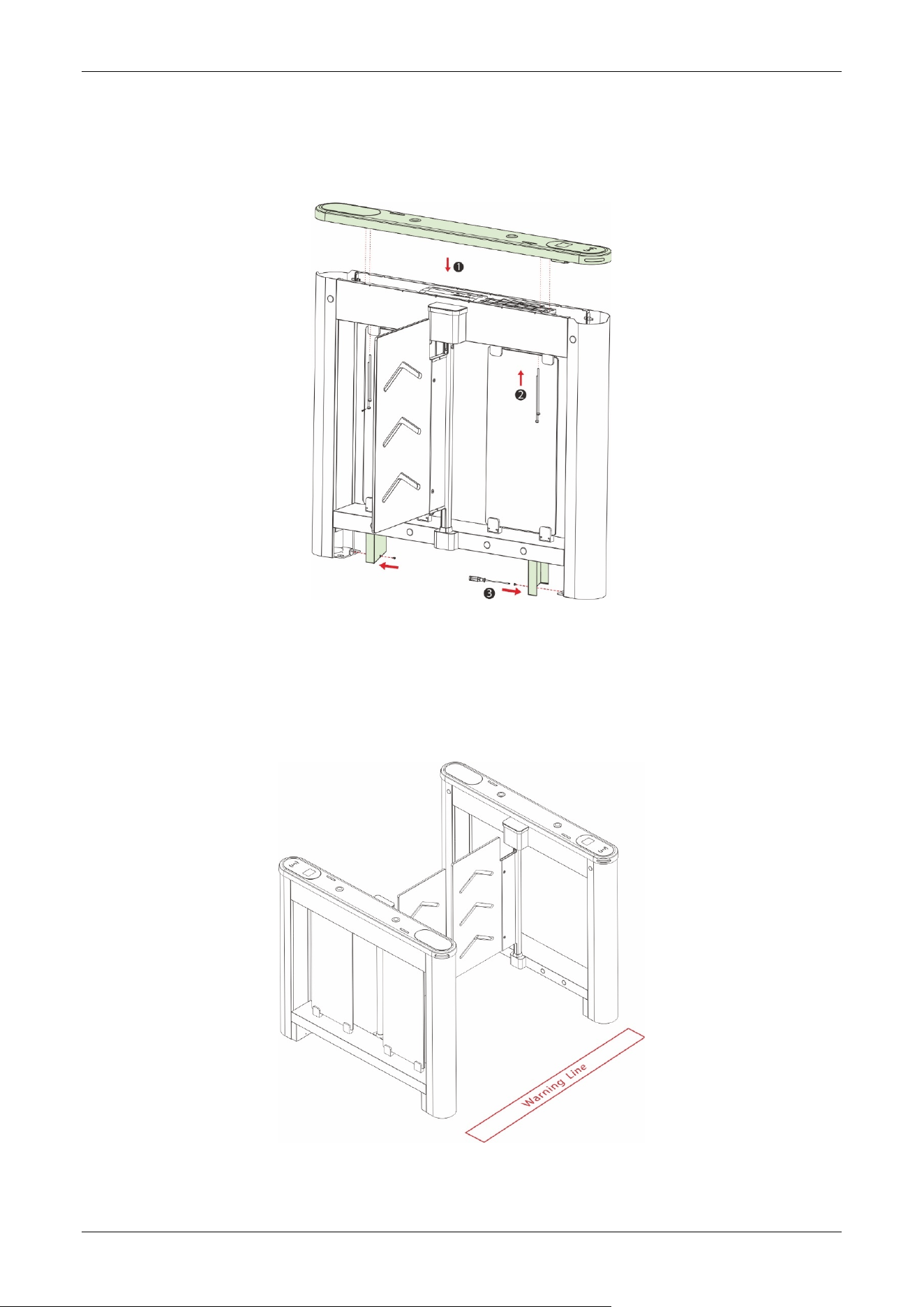
Step 1 Remove the Top Lid and Expansion Screw Cover Plate
1. Remove the four screws of the expansion screw cover plate under the bottom beam, and then remove
the cover plate.
2. Remove the four screws hidden under the top lid, then remove the top lid.
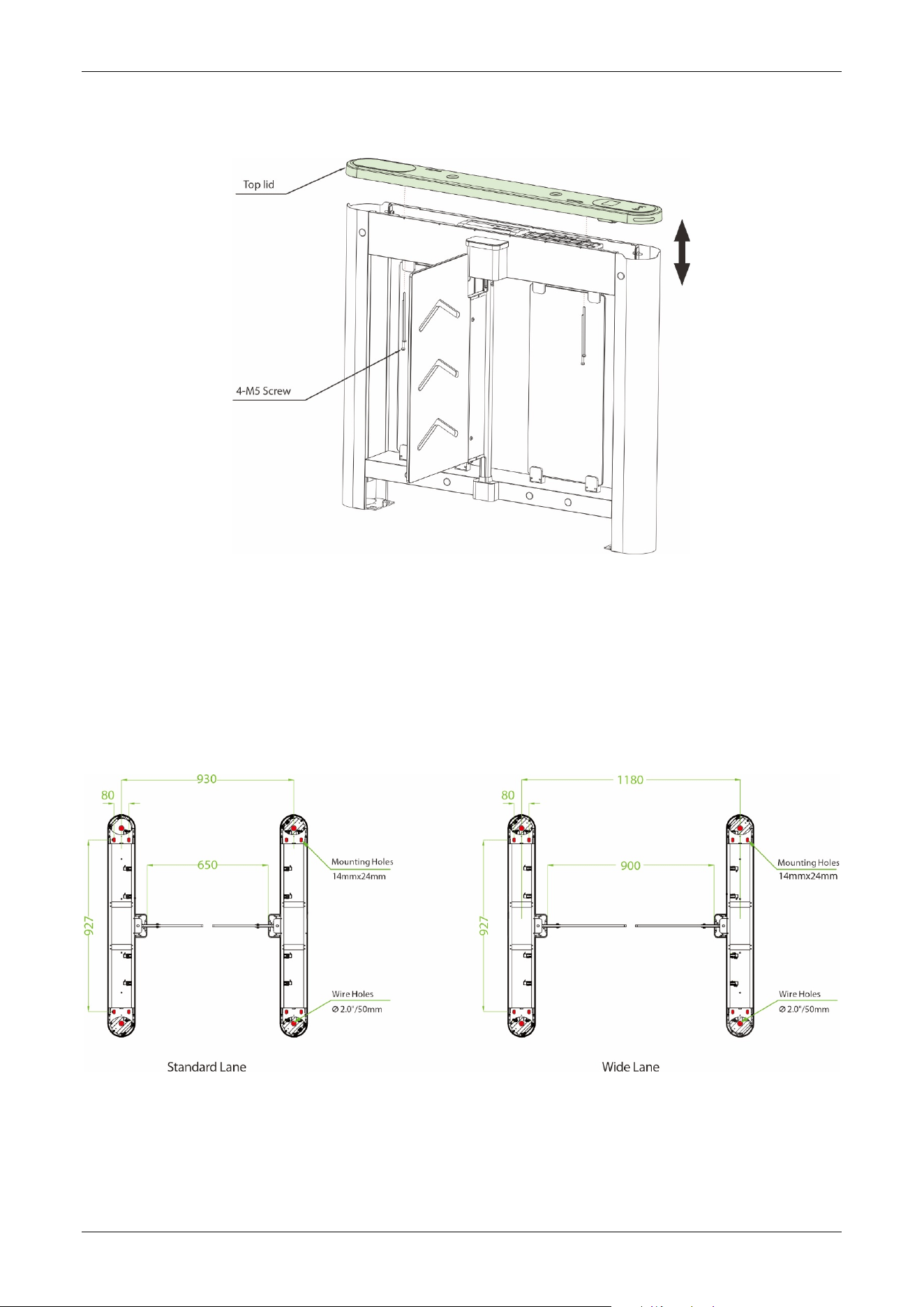
Saturn-S1000 Pro Series User Manual
Page | 26 Copyright©2026 ZKTECO CO., LTD. All Rights Reserved.
Step 2 Determine the Mounting Location
1. Please refer to the user's manual and complete the power-on self test operation before installation.
2. Then place the cabinet according to the mounting distances shown in the diagram below. Take care to
measure the distance between the bottom inside walls of the cabinets on the entrance side and exit
side of the channel and make sure that the measurements are consistent.
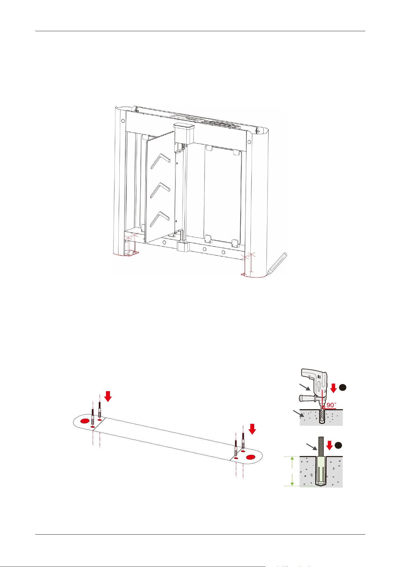
Saturn-S1000 Pro Series User Manual
Page | 27 Copyright©2026 ZKTECO CO., LTD. All Rights Reserved.
Step 3 Marker Position
Draw the location of the cabinet with a marker and mark each location of the mounting holes. There will be
a total of four mounting holes and two wire holes per cabinet.
Step 4 Drill Holes and Place Bolts
1. Using a concrete drill bit, drill the mounting holes 60mm in depth at the center of each marked
location.
2. Then insert the bolts vertically into the mounting holes as shown at right.
3. Make sure the bolts are placed in place. Use a hammer to tap the bolts into place, if needed.
Concrete
60mm
2
1
Bolt
Percussion Drill
Place bolts into mounting holes
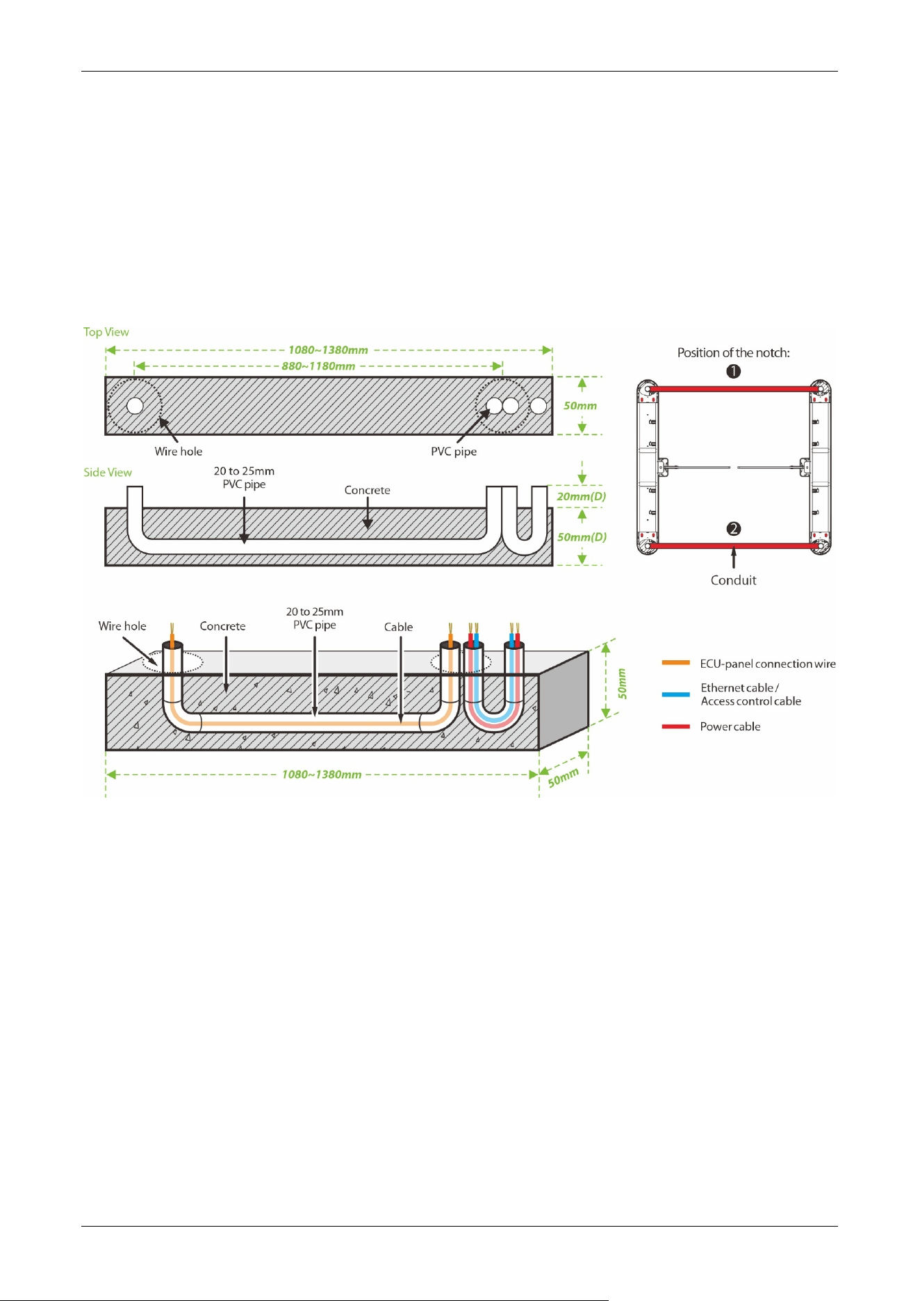
Saturn-S1000 Pro Series User Manual
Page | 28 Copyright©2026 ZKTECO CO., LTD. All Rights Reserved.
Step 5 Wireway Laying
1. Dig a recess of 50mm depth between the wire holes on both sides of the channel with the dimensions
shown below. Recesses can be dug at positions ❶ and ❷.
2. Then lay two 25mm diameter PVC pipes as shown below.
3. After threading the cable out of the PVC pipe, pour concrete to f ix it in place.
Step 6 Fixed Cabinet
1. After laying the PVC pipe, place the cabinet alignment bolts back into the mounting position.
2. Then insert the four washers and nuts into the bolts one by one.
3. Tighten the nuts to hold the cabinet in place. Don't tighten it completely until after you're sure it won't
move anymore. The finished result is shown below:
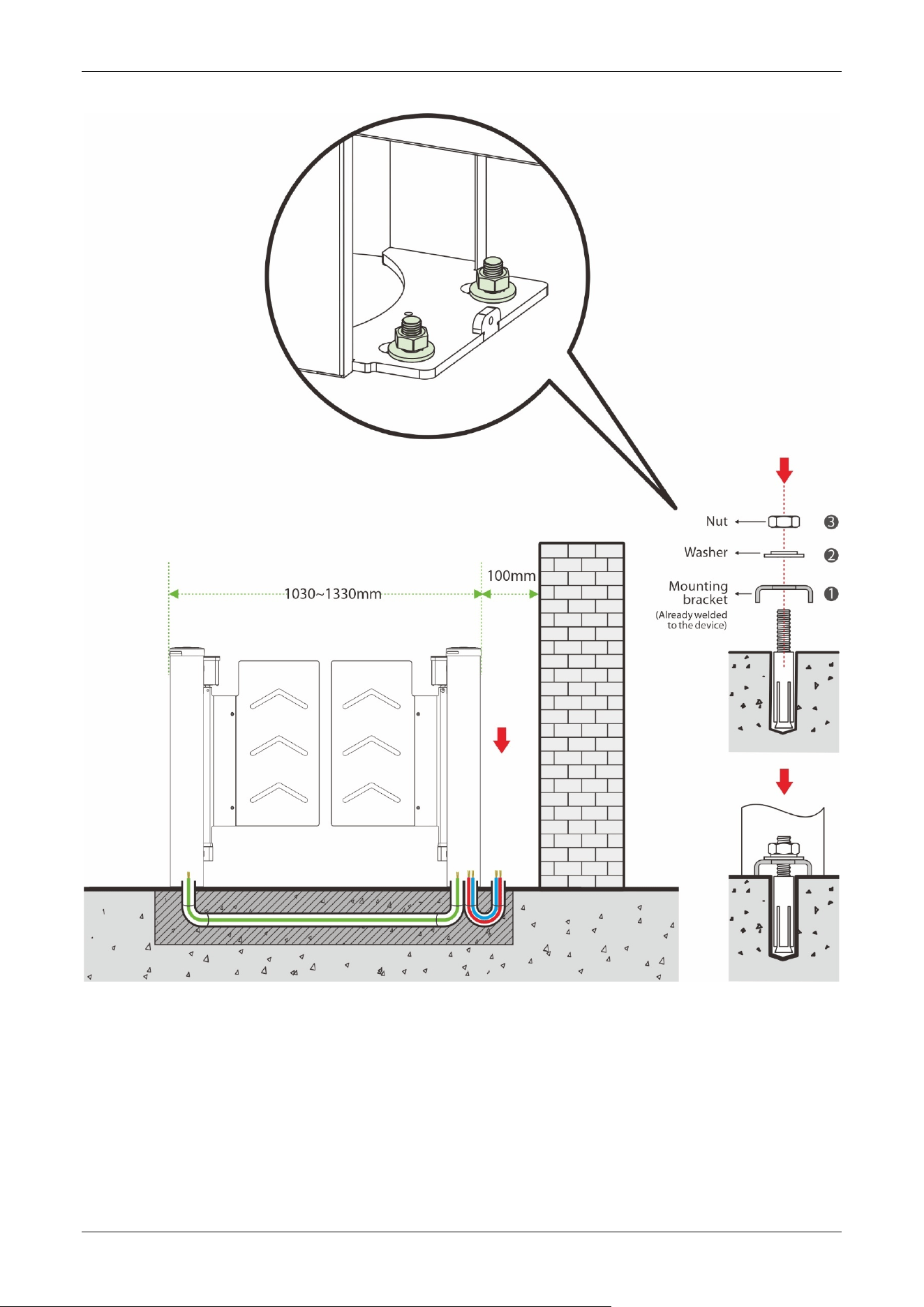
Saturn-S1000 Pro Series User Manual
Page | 29 Copyright©2026 ZKTECO CO., LTD. All Rights Reserved.
Saturn-S1000 Pro Series User Manual
Page | 30 Copyright©2026 ZKTECO CO., LTD. All Rights Reserved.
Step 7 Close the Top Lid and Expansion Screw Cover Plate
Close the top lid and expansion screw cover plate, and secure with screws.
Step 8 Marking the Warning Line
1. It is recommended that warning lines be marked on the ground and used to alert users.
2. A warning line can alert users to wait outside the line until the previous user completes the verification
process and passes through the turnstile.
Saturn-S1000 Pro Series User Manual
Page | 31 Copyright©2026 ZKTECO CO., LTD. All Rights Reserved.
Accessory Installation
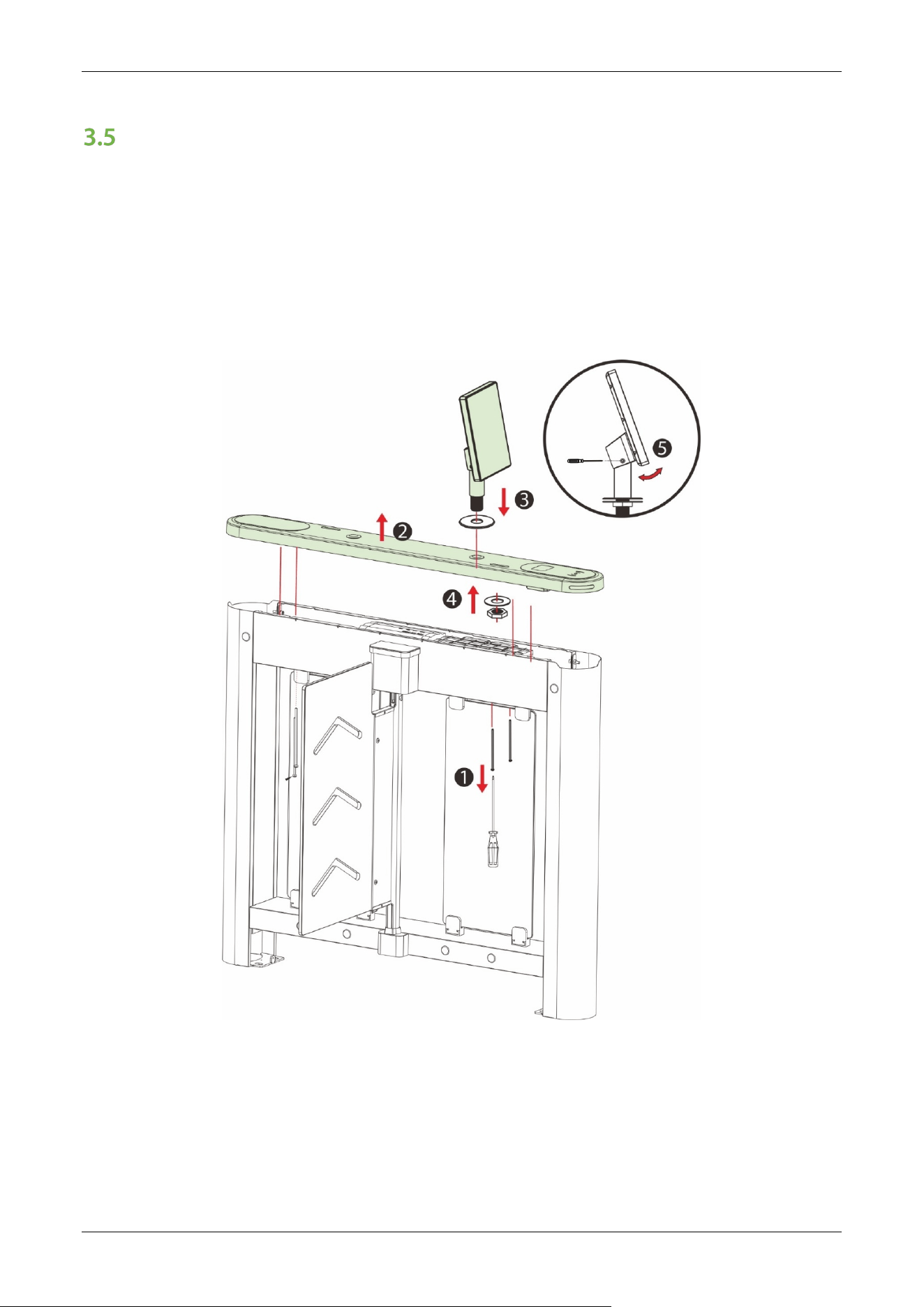
3.5.1 Facial Authentication Terminal Installation
1. Remove the top cover plate and route the unit's cables through the pre-drilled mounting holes.
2. Pass the mounting bracket through the mounting holes.
3. Place the gasket and nut and tighten the nut to secure the unit.
4. Adjust the unit to a suitable angle.
Saturn-S1000 Pro Series User Manual
Page | 32 Copyright©2026 ZKTECO CO., LTD. All Rights Reserved.
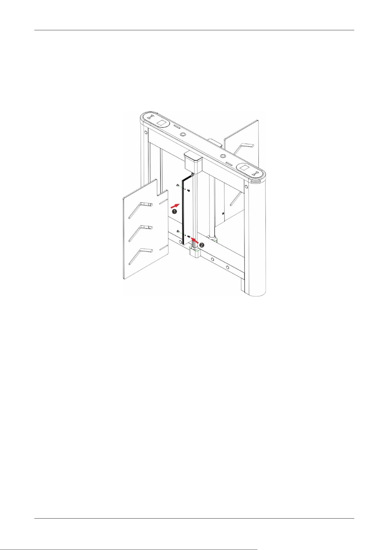
3.5.2 Swing Barrier Installation
1. Push the swing barrier into the clamping block.
2. Lock the swing barrier with the screws.
Saturn-S1000 Pro Series User Manual
Page | 33 Copyright©2026 ZKTECO CO., LTD. All Rights Reserved.
4 Terminal Description
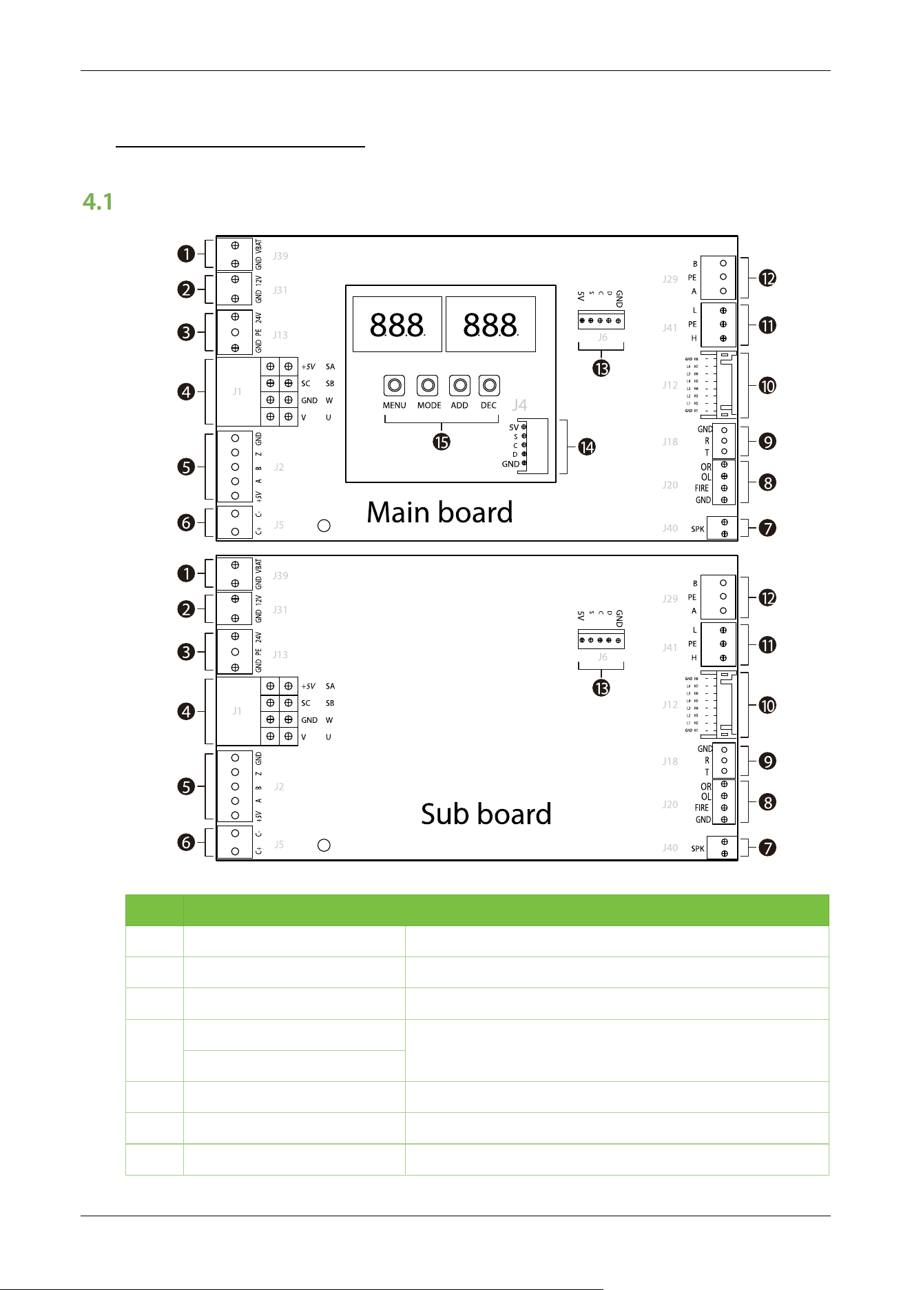
Main and Sub Board
NO. Terminal Descriptions
1 GND, VBAT Fire panel interface
2 GND, 12V 12V DC power supply input
3 GND, PE, 24V 24V DC power supply input
4
+5V, SC, GND, V
Motor interface
SA, SB, W, U
5 +5V, A, B, Z, GND Encoder interface
6 C+, C- Clutch
7 SPK Speaker
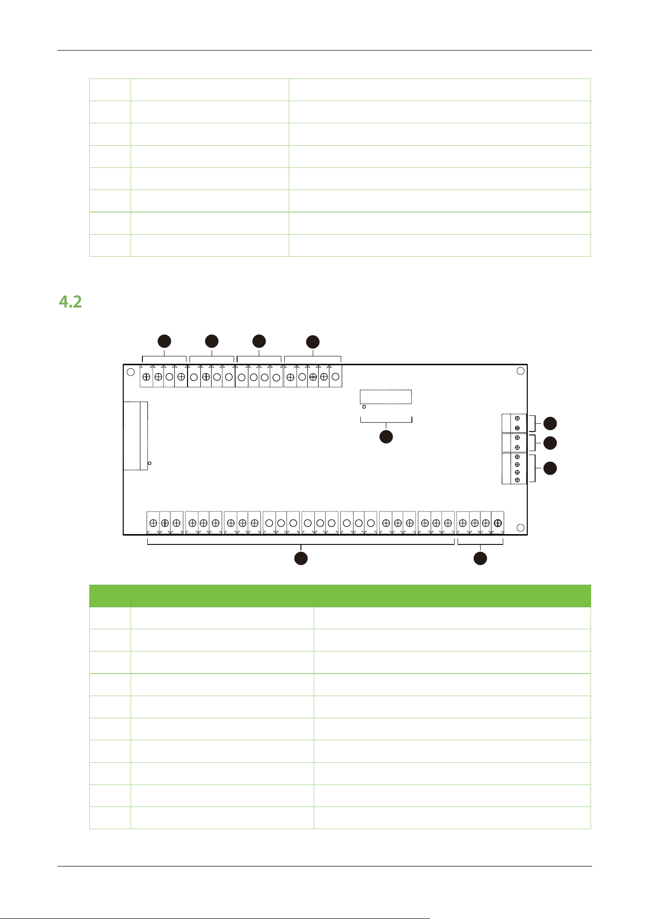
Saturn-S1000 Pro Series User Manual
Page | 34 Copyright©2026 ZKTECO CO., LTD. All Rights Reserved.
8 OR, OL, FIRE, GND Fire Control Port, Right Open, Left Open
9 GND, R, T RS232 communication
10 GND, L1-L6, GND; H1-H8 Interface board infrared communication interface
11 L, PE, H CAN communication interface
12 B, PE, A RS485 communication
13 5V, S, C, D, GND Keypad interface
14 5V, S, C, D, GND Keypad interface
15 MENU, MODE, ADD, DEC Control buttons for setting menu parameters
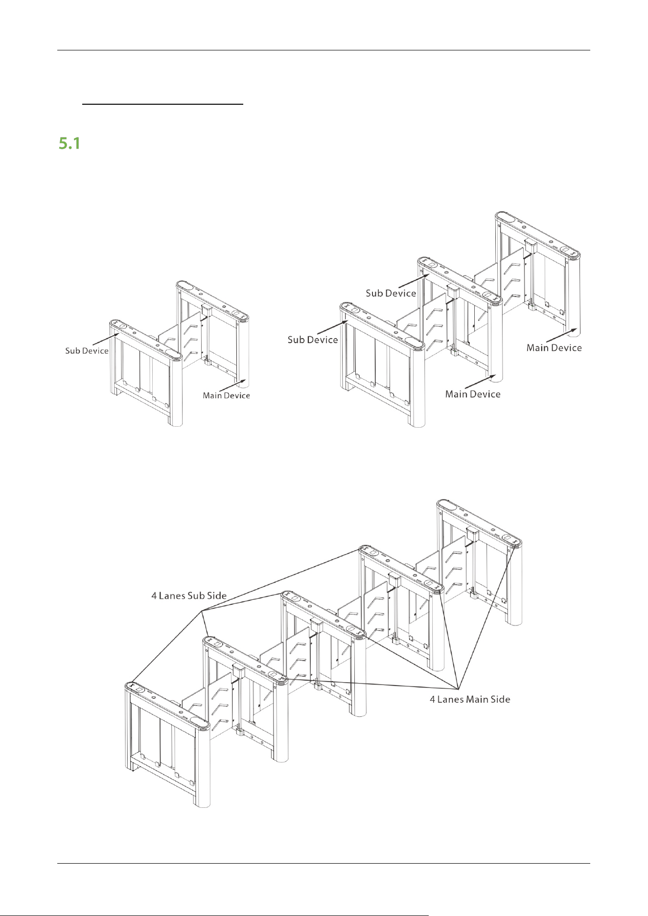
IR Sensor Board
J11
2
15
16
J10
J19
J15
H1
J3
J4
J7
J5
J2
J1
BAT
GND
GND
GND
GND
GND
GND
GND
GND
GND
GND
GND
GND
GND
12V
12V
12V
GND
12V
R
G
ND
B
G
12V
GND
OR
OL
FI
OL
OR
FI
H8
12V
H7
12V
H6
12V
H
5
12V
H4
12V
H3
12V
H2
12V
H1
12V
L3
R3
L2
R2
R1
L1
J8
J6
J9
J
1
3
J
1
4
J
1
6
1
23
4
5 6
7
8
9
10
NO. Terminal Descriptions
1 12V, B, G, R,GND Wing arm light bar interface
2 12V, L3, R3, GND Top light interface
3 12V, L2, R2, GND Top light interface
4 12V, L1, R1, GND Top light interface
5 12V, H1-8, GND Infrared sensor interface
6 OR, OL, FI, GND External fire port
7 OR, OL, FI, GND Alarm, fire opening port
8 12V, GND 12V DC power supply input
9 BAT, GND Backup firefighting power interface
10 J11 Main board communication interface
Saturn-S1000 Pro Series User Manual
Page | 35 Copyright©2026 ZKTECO CO., LTD. All Rights Reserved.
5 Wiring Instructions
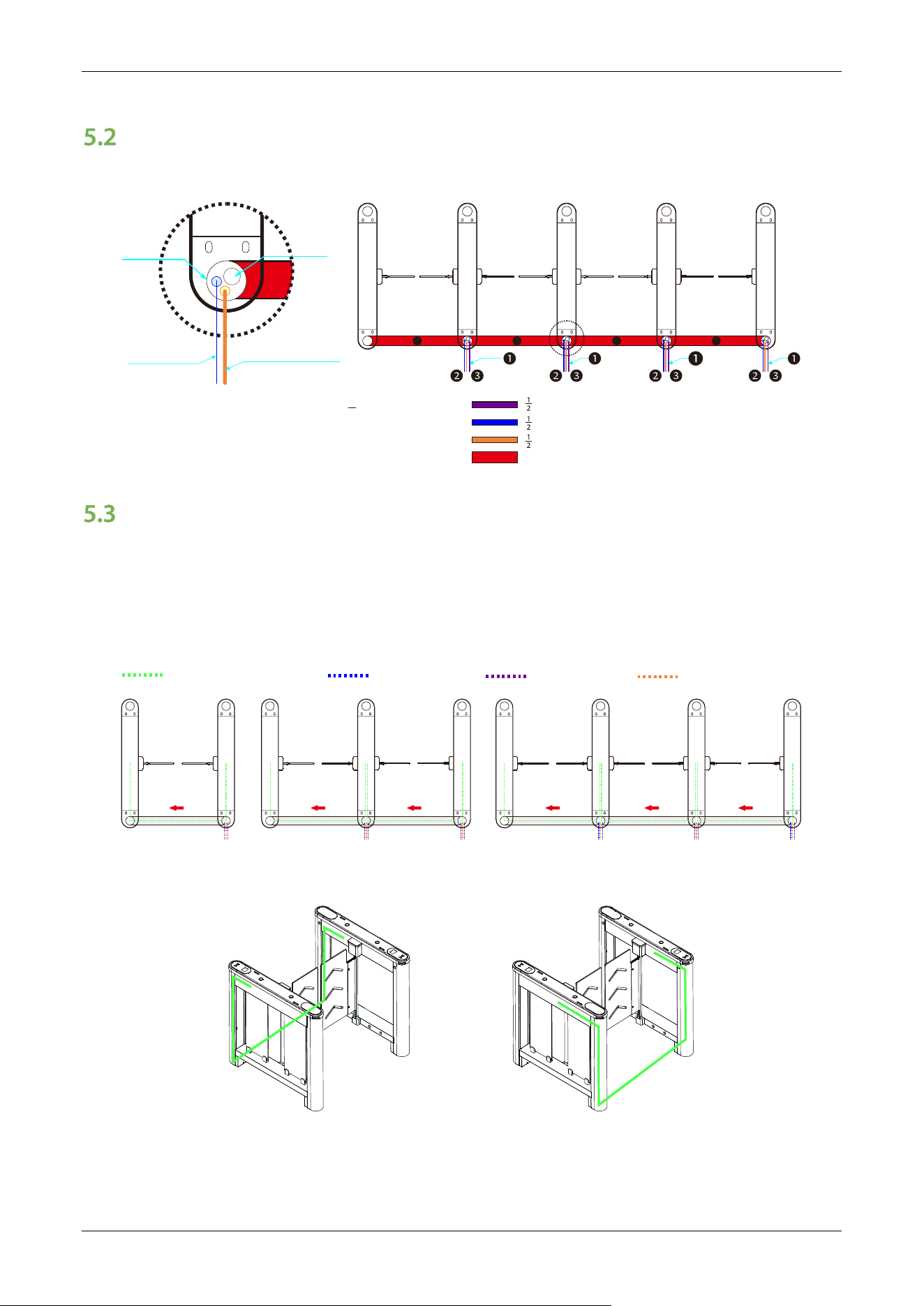
Main-Sub Location
The positions of the main and sub corresponding to single-lane, dual-lane and multi-lane are shown
in the figure below.
Single - Lane Dual - Lane
Multi - Lane
Saturn-S1000 Pro Series User Manual
Page | 36 Copyright©2026 ZKTECO CO., LTD. All Rights Reserved.
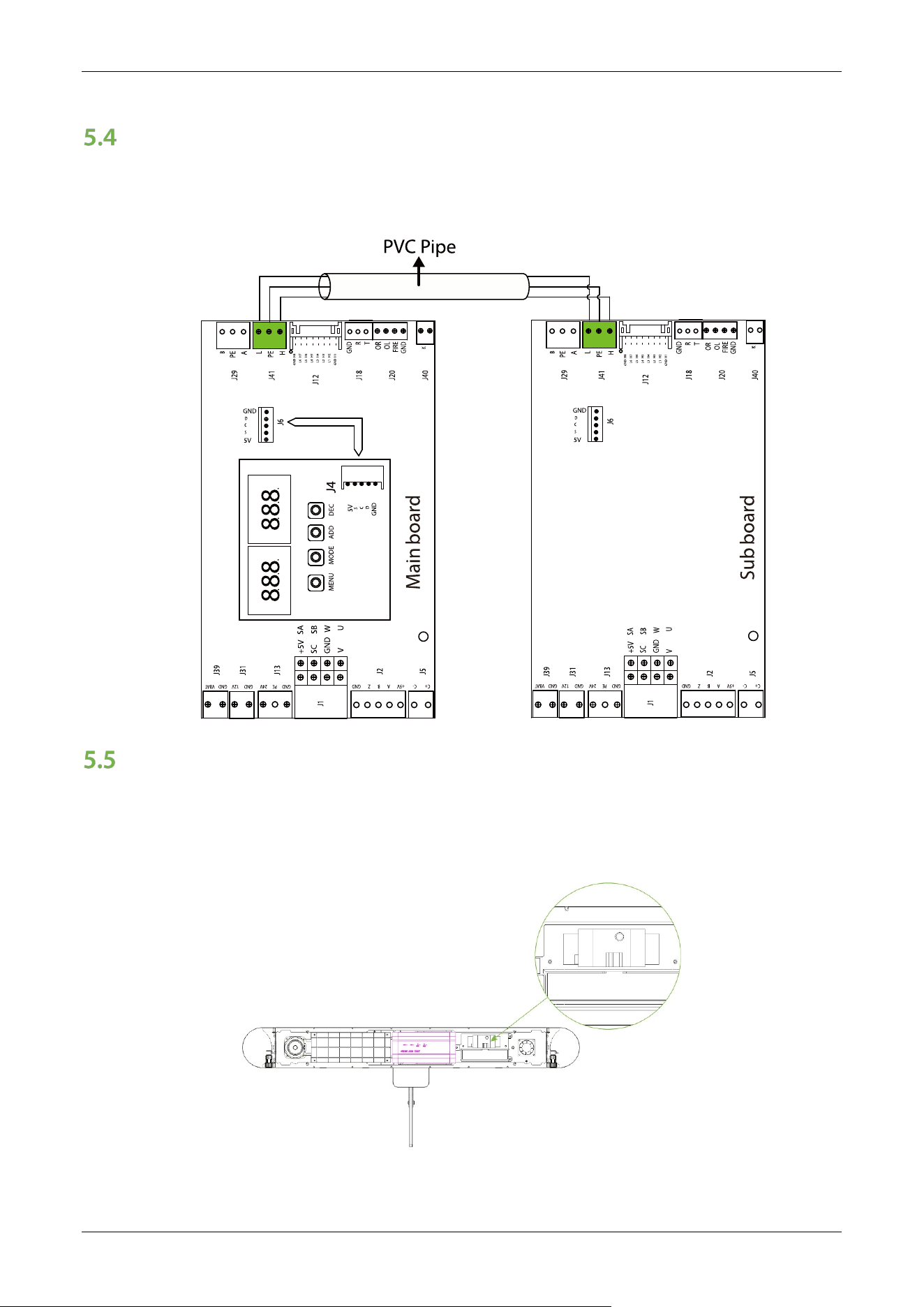
Slotting Position
For the different channels, the slotted locations are shown below.
" conduit reserved for FIRE/Relay input
" conduit reserved for AC 110V input
" conduit reserved for reader/access controller wiring
1" conduit used for connection wire harness between M/S
❶
❷
❸
❹
Conduit hole maximum can f it 1" conduit and 2 pcs " conduits.
1. 8-core connecting wire and LAN cable through 1" conduit together.
2. Folded 8 pin connector during through conduit.
2
1
4
Lane1Lane2Lane3Lane4
4 4
4
AC power input
Access controller cable
∅
1.0"(25mm)
∅
2.2"(56mm)
FACP
Wiring Methods
The wiring principle is to connect the main device to the sub device and communicate via the ECU-
panel connection wire. Each main device is then powered individually. The following diagram shows
how the different channels are wired.
Single-lane
Dual-lane Multi-lane
Wiring Instructions
5-core connecting wire(M-S)
AC110/220V input
Access controller cable
FACP(Fire alarm)
LANE1 & LANE3, Wiring connection
between M/S device, as shown
red/green dash lines
LANE2 & LANE4, Wiring connection
between M/S device, as shown
red/green dash lines
Saturn-S1000 Pro Series User Manual
Page | 37 Copyright©2026 ZKTECO CO., LTD. All Rights Reserved.
Main and Sub Connection Cable
Pass the Main and sub connecting wires through the PVC tubing and then plug them into the J41
ports respectively to communicate as shown below.
Power and Air Switch Wiring
110V /220V AC primary power must be hard wired in place (Note: must be grounded). It is strongly
recommended that a licensed electrician perform this procedure in accordance with applicable local
codes.
Air Switch
Saturn-S1000 Pro Series User Manual
Page | 38 Copyright©2026 ZKTECO CO., LTD. All Rights Reserved.
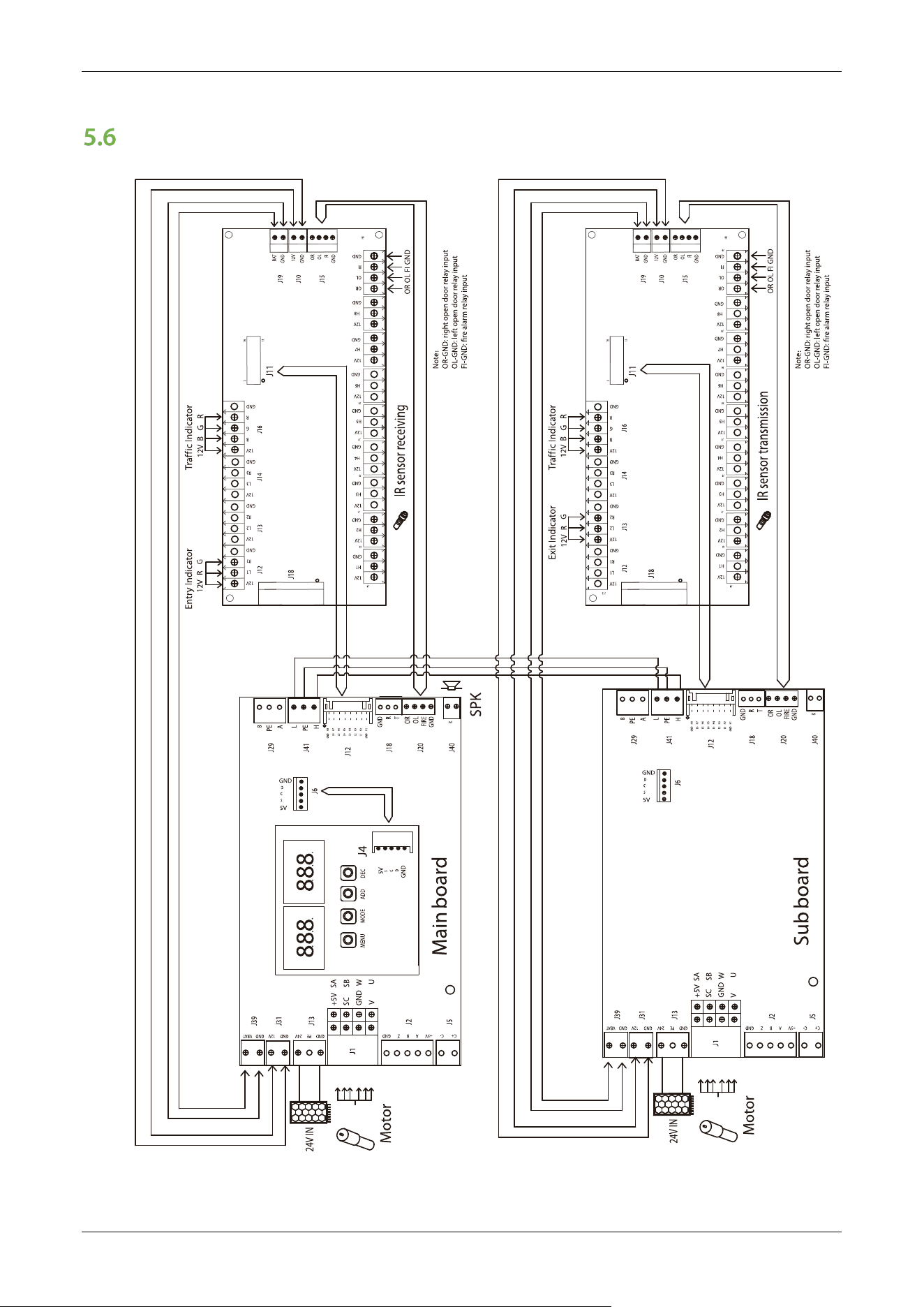
System Wiring Diagram
Saturn-S1000 Pro Series User Manual
Page | 39 Copyright©2026 ZKTECO CO., LTD. All Rights Reserved.
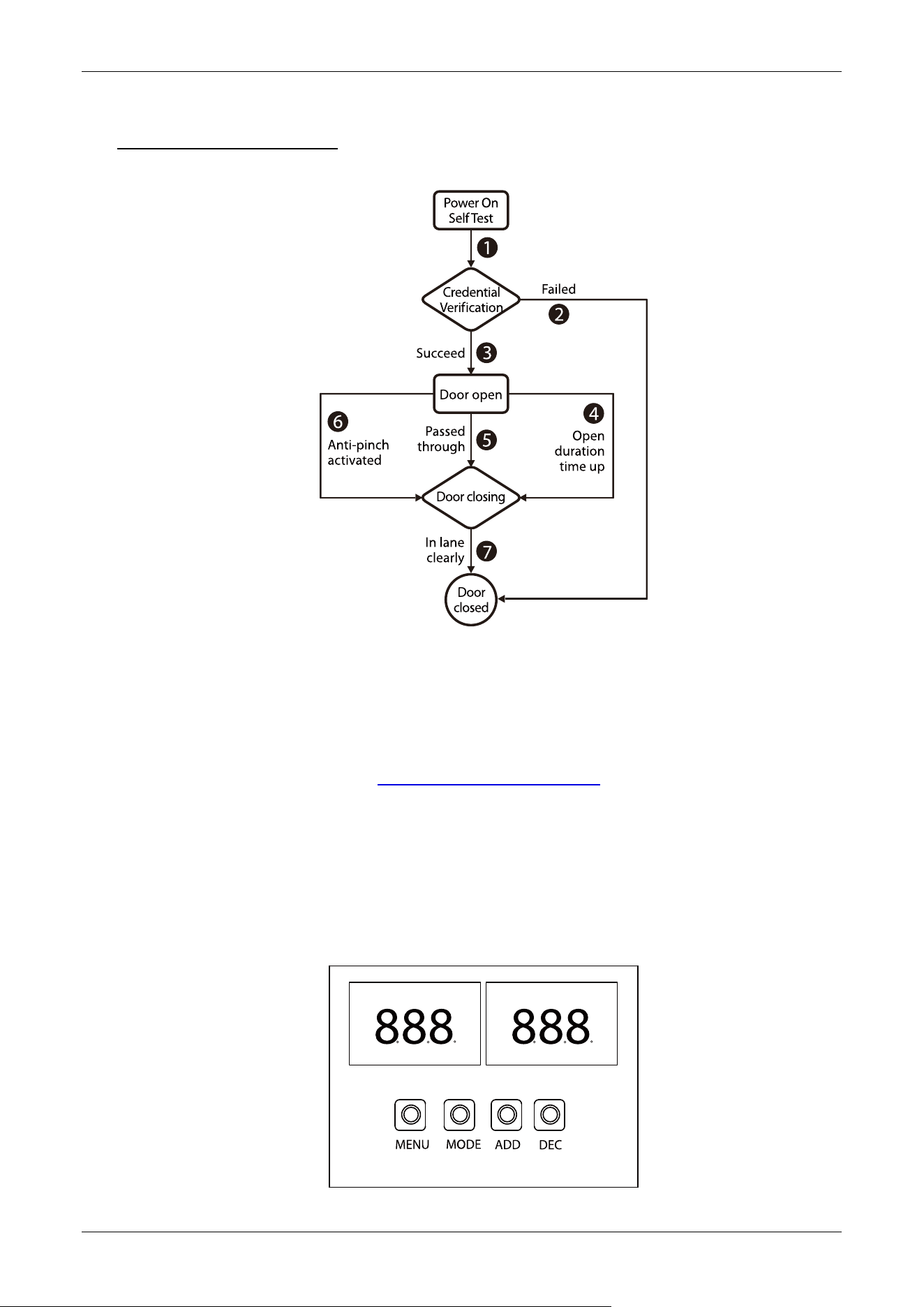
6 Operation Process
1. POST (Power On Self Test)
When powering up the unit, wait 30 seconds for the system to perform a POST (Power On Self Test)
procedure. If no problems are detected, the unit will operate normally. If a fault is detected, the
system will display a relevant message on the LCD display so that the user can quickly understand
and solve the problem. (Reference 5.5 Power and air switch wiring for connecting the air switch and
power supply.)
2. Credential Verification
After the unit's power on self test is complete, you can test the door opening by pressing the ADD/
DEC button on the motherboard.

Saturn-S1000 Pro Series User Manual
Page | 40 Copyright©2026 ZKTECO CO., LTD. All Rights Reserved.
When the user presses the ADD/ DEC button on the main board, it is equivalent to recognizing a
valid card. The LCD display will show success and a buzzer will give a positive audible indication to
the pedestrian that it has been successfully validated. The card reader then sends a signal to the
access controller requesting permission to pass through the channel. The access controller will send
a signal to the revolving door control panel. After receiving the signal from the card reader and the
Infrared Sensor, the Turnstile Control Board will send valid control signals to the servo motor driver.
1) Verification Success
When the verification is successful, the door is opened.
2) Validation Failure
When verification fails, the door remains closed.
Note: At this time, if the system is in forbidden passing mode, the mode indicator light will turn red,
and the Turnstile Control Board will not accept signals of card.
3. Passed Through
After the passenger passes the channel according to the opening direction of the swing arm, the
Infrared Sensor will keep detecting the movement of the pedestrian throughout the passage and
continue to deliver signals to the Turnstile Control Board until the pedestrian passes through the
passage.
If the pedestrian enters without ID or an invalid card, the system will prompt an audible alarm. The
alarm signal will not be canceled until the passenger retreats from the passage. The pedestrian can
pass through the passage only after a valid card is successfully verified.
Saturn-S1000 Pro Series User Manual
Page | 41 Copyright©2026 ZKTECO CO., LTD. All Rights Reserved.
7 Machine Operation
Operation Buttons Description
GND H1
L1 H2
L2 H3
L3 H4
L4 H5
L5 H6
L6 H7
H8GND
C+ C- GNDZBA+5V GND PE 24V GND 12V GND VBAT
+5V
SC
GND
V
SA
SB
W
U
J5
J2
J1
J13
J31
J12
J18
J20
O
R
O
L
F
IR
E
G
N
D
G
N
D
R
T
J39
J29
J41
J40
Ma boardin
SPK
B
L
PE
A
H
PE
888
888
DECADDMODEMENU
GND
C
D
S
5V
G
ND
C
D
S
5V
J6
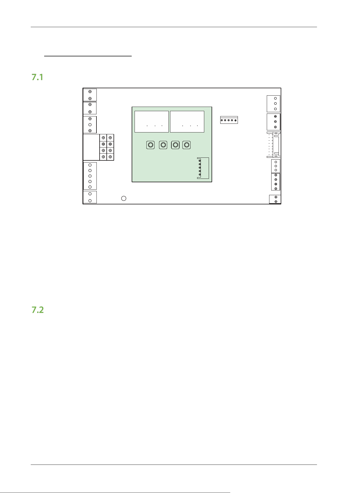
There are 4 keys on the main motor driving controller, "MENU", "MODE", "ADD" and "DEC".
Operation Buttons Description:
MENU: Used to access the Settings menu and confirm modified values
MODE: Returns to the previous menu and cancels the current operation.
ADD: Navigate to the upper menu item and increase the value.
DEC: Navigate to the lower menu item and decrease the value.
Menu Parameter Settings
01EXXX : Display Mode
01E000: Displays current position of the gate
01E001: Infrared input signal
01E002: Controls input signal
01E003: Test mode (the digital LED displays "---" in the test mode)
01E004: Version number
Saturn-S1000 Pro Series User Manual
Page | 42 Copyright©2026 ZKTECO CO., LTD. All Rights Reserved.
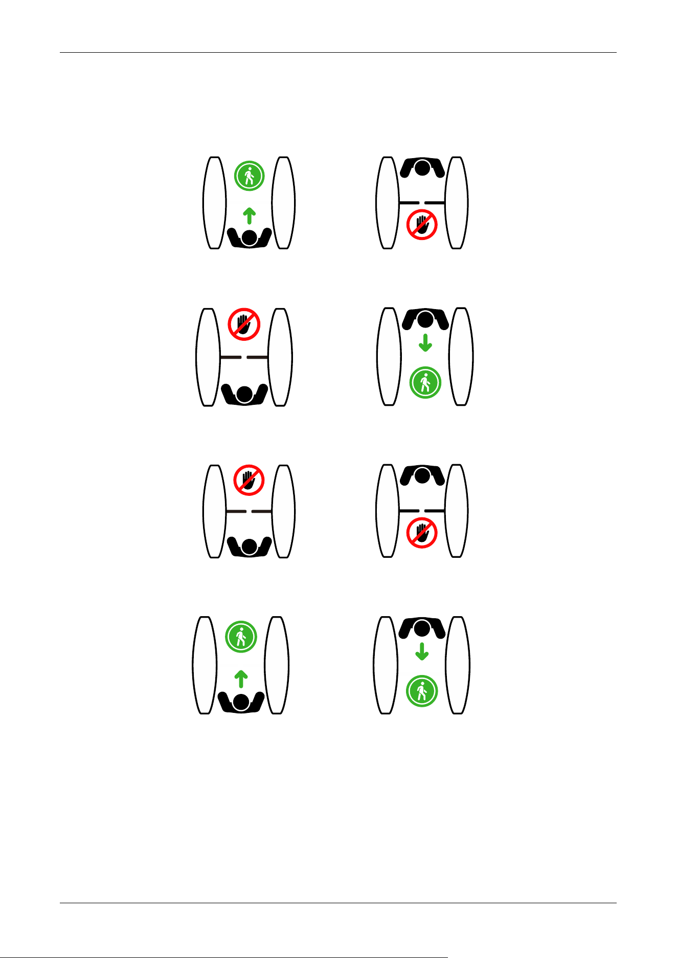
02EXXX : Device Mode
02E001: Entry: free, Exit: prohibited
NO EXIT
ENTRY
02E002: Entry: prohibited, Exit: free
EXIT
D O NOT ENT R Y
02E003: Entry & Exit: prohibited
DO NOT ENTRY
NO EXIT
02E04: Entry & Exit: free
EXIT
ENTRY
Saturn-S1000 Pro Series User Manual
Page | 43 Copyright©2026 ZKTECO CO., LTD. All Rights Reserved.
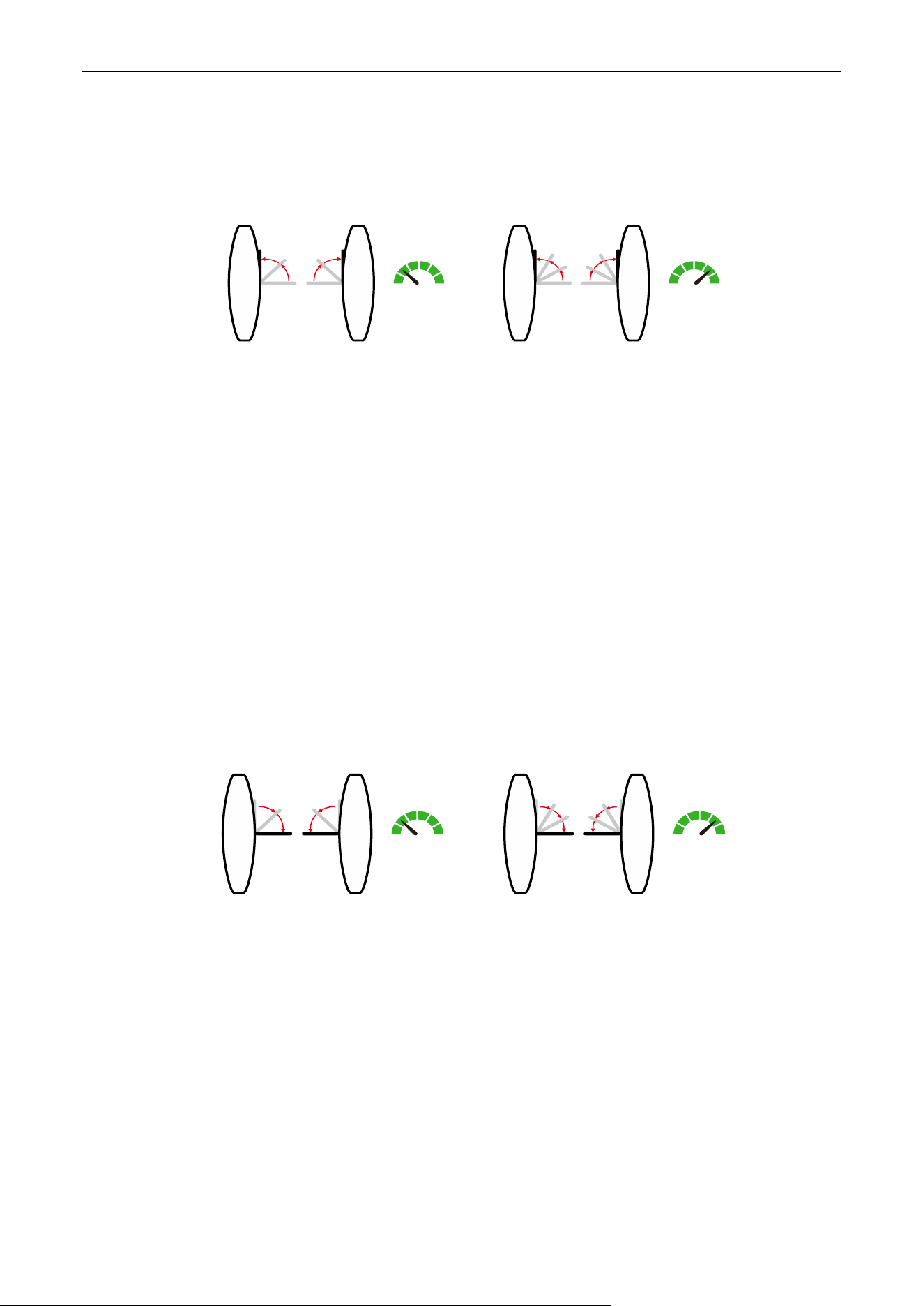
03EXXX : Gate Opening Speed
To adjust the gate opening speed, you can set a larger number for a faster opening. The Gate
Opening Speed can be configured between 5 and 22, with a default value of 18.
5 22
Speed
5 22
Speed
Open Open
04EXXX : Gate Opening Deceleration Distance
A larger number increases the deceleration time, enhancing the stability of the wing arm operation.
The Gate Opening Deceleration Distance can be set between 0 and 50, with a default value of 10.
05EXXX : Gate Opening Compensation Speed
This setting is used when the wing arm cannot fully open or shakes during operation. A larger
number results in faster compensation speed. The Gate Opening Compensation Speed can be set
between 0 and 50, with a default value of 12.
06EXXX : Gate
Closing Speed
To adjust the gate closing speed, you can set a larger number for a faster closing. The Gate Closing
Speed can be configured between 5 and 22, with a default value of 18.
5 22
Speed
5 22
Speed
Close
Close
07EXXX : Gate Closing Deceleration Distance
A larger number increases the deceleration time, enhancing the stability of the wing arm operation.
The Gate Closing Deceleration Distance can be set between 0 and 50, with a default value of 10.
08EXXX : Gate Closing Compensation Speed
This setting is used when the wing arm cannot fully close or shakes during operation. A larger
number results in faster compensation speed. The Gate Closing Compensation Speed can be set
between 0 and 50, with a default value of 12.
Saturn-S1000 Pro Series User Manual
Page | 44 Copyright©2026 ZKTECO CO., LTD. All Rights Reserved.
09EXXX : Main and Sub Settings
This setting is used to set the main and sub device.
09E000 : Main device
09E001 : Sub device (Default)
10EXXX : RS485 Address
It can be set between 0 to 254 and the default value is 0.
11EXXX : Open Duration Time
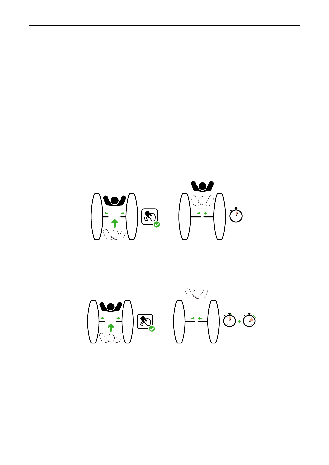
The valid time period after a successful verification can be configured. Once the set time is reached,
the gate will automatically close. The longer the number set, the longer the valid time. The valid
value ranges from 2 to 60 seconds, with a default value of 5 seconds.
2-60s
After
RFID
12EXXX : Gate Closing Delay Time
Set the delay time of gate closing after passing. The valid value for gate closing delay time can be
set between 0 to 60 seconds and the default value is 0 seconds.
2-60s
After
RFID
0-60s
13EXXX : In Place Position Adjustment
This setting is used to adjust the wing arm to close in place/open in place. Note: The wing arm
needs to be in the corresponding position during commissioning.
13E001 : Wing arm close in place adjustment
13E002 : Right in place adjustment
13E003 : Left in place adjustment
Saturn-S1000 Pro Series User Manual
Page | 45 Copyright©2026 ZKTECO CO., LTD. All Rights Reserved.
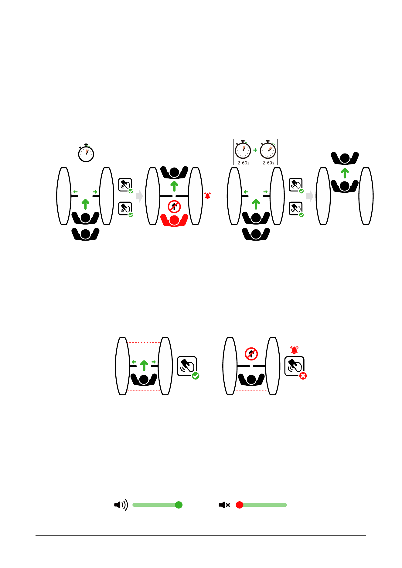
14EXXX : Gate Opening Memory
When more than two legal access signals are given at the same time (including the same direction
and the opposite direction), the system will remember all pass requests and complete each pass in
turn.
14E000: Close (Default)
14E001: Open
# 1 RFI D
# 2 RFI D
14E000
# 1 RFI D
# 2 RFI D
14E00 1
2-60s
15EXXX : Authentication in Lane
It allows pedestrian verification during the IR sensor triggered.
15E000: Allow (Default)
15E001: Forbidden
RFID RFID
Allow
Authentication in Lane
(default)
Forbidden
Authentication in Lane
16EXXX : Volume Setting
Volume Setting is used for adjusting the volume of the device. The larger the number is set, the
louder the volume. The valid value for Volume Setting can be set between 1 to 100 and the default
value is 70.
100
100
Saturn-S1000 Pro Series User Manual
Page | 46 Copyright©2026 ZKTECO CO., LTD. All Rights Reserved.
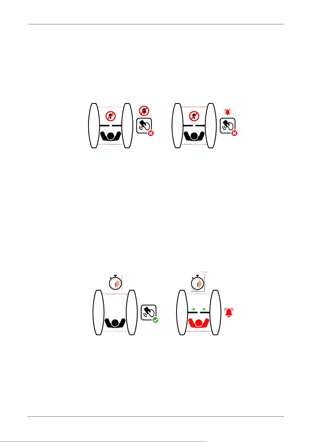
17EXXX : Close Alarm Tone
When the alarm tone is turned off, the Turnstile will not emit an alarm tone when encountering an
alarm situation. The following figure shows an example of the prohibition of authentication in lane:
17E000: Close
17E001: Open (Default)
RFID
Close Alarm Tone Open Alarm Tone
(default)
RFID
18EXXX : Infrared Pair Count
Sets the number of infrared beam pairs used for personnel detection. The configurable range is 1
to 6, with a default value of 6.
If the installed hardware configuration exceeds 8 pairs of infrared beam, the system interface will
uniformly display 22 for unified management.
19EXXX : Stay Duration Time
Set the duration of stay in the channel after successful verification. After exceeding the set time,
the device will alarm to indicate. The valid value for Stay Duration Time can be set between 5 to 30
seconds and the default value is 10 seconds.
RFID
5-30s
5-30s
After
Stay Stay
20EXXX : Force Adjustment
The larger the number, the greater the efficiency of the gate opening and closing force. The valid
value for Force Adjustment can be set between 10 to 100 and the default value is 50.
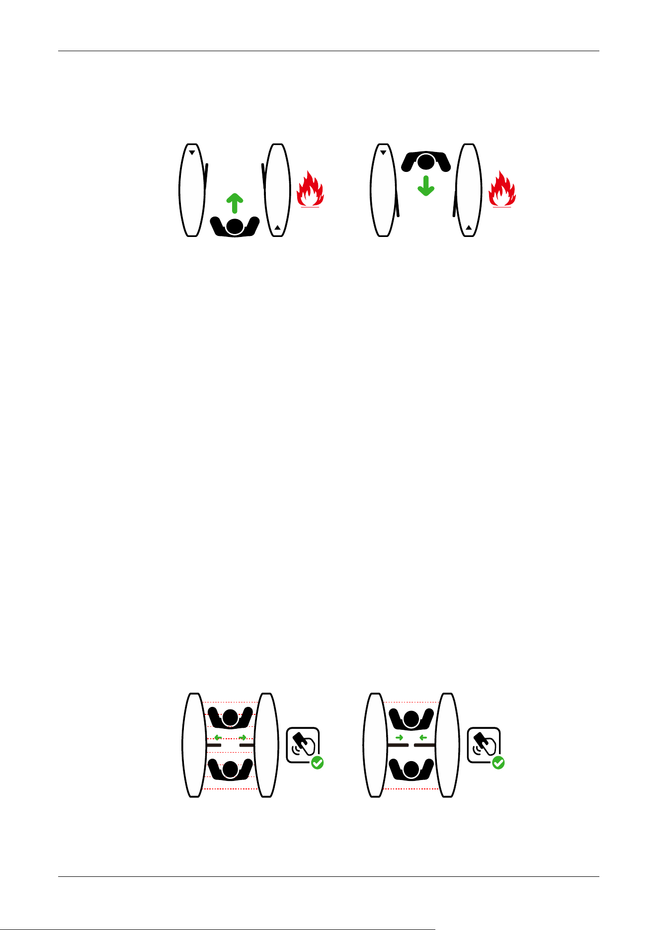
21EXXX : Fire Mode
Saturn-S1000 Pro Series User Manual
Page | 47 Copyright©2026 ZKTECO CO., LTD. All Rights Reserved.
21E000: Entry opening (Default)
21E001: Exit opening
ENTRY
EXIT
22EXXX : Clutch Start Angle
Set the angle at which the clutch starts. The larger the number, the bigger the angle. The valid
value for Clutch Start Angle can be set between 0 to 99, and the default value is 0. 0 not locked,
adapted to movements without clutch
23EXXX : Clutch Alarm Setting
23E000: Automatic Unlock (Default)
23E001: Authorized Unlock
When the gate is unlocked in an unauthorized way, the clutch gets locked automatically.
24EXXX : Restore Factory Setting
24E001: Restore factory settings
24E002: Reboot
25EXXX : Anti-pinch Area Setting
25E000: All Infrared anti-pinch (Default)
25E001: First and last pair are not anti-pinch
RFID
RFID
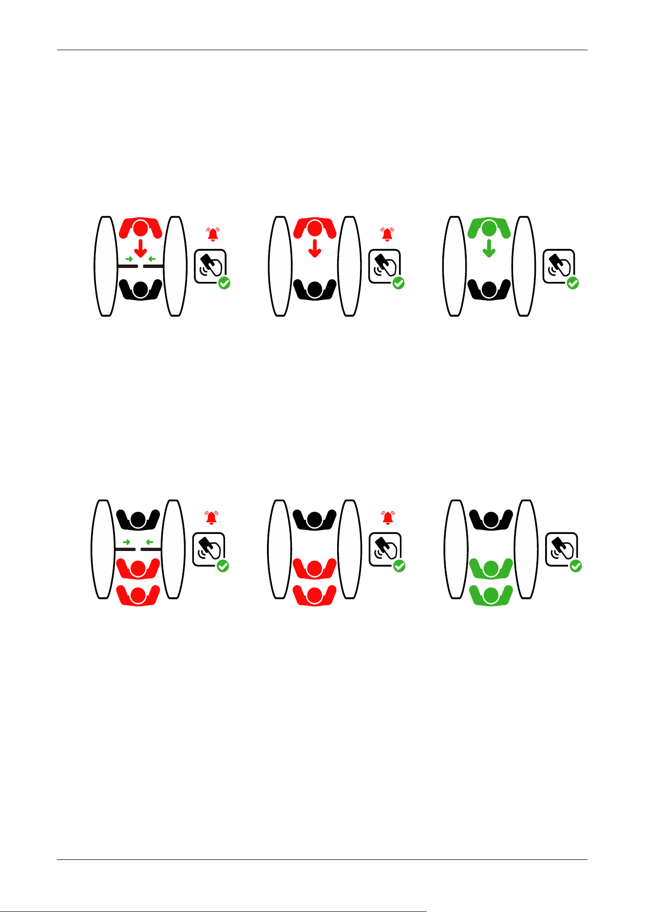
26EXXX : False Direction Entry
Saturn-S1000 Pro Series User Manual
Page | 48 Copyright©2026 ZKTECO CO., LTD. All Rights Reserved.
The False Direction Entry (26E000) will only be effective when the Anti-pinch Area Setting is set to
(25E001).
26E000: Close (For wing gates)
26E001: Only alarm (Default)
26E002: No detection
RFID
RFID
RFID
27EXXX : Anti-tailgate Setting
The Anti-tailgate Setting (27E000) will only be effective when the Anti-pinch Area Setting is set to
(25E001).
27E000: Close (For wing gates)
27E001: Only alarm (Default)
27E002: No detection
RFID
RFID
RFID
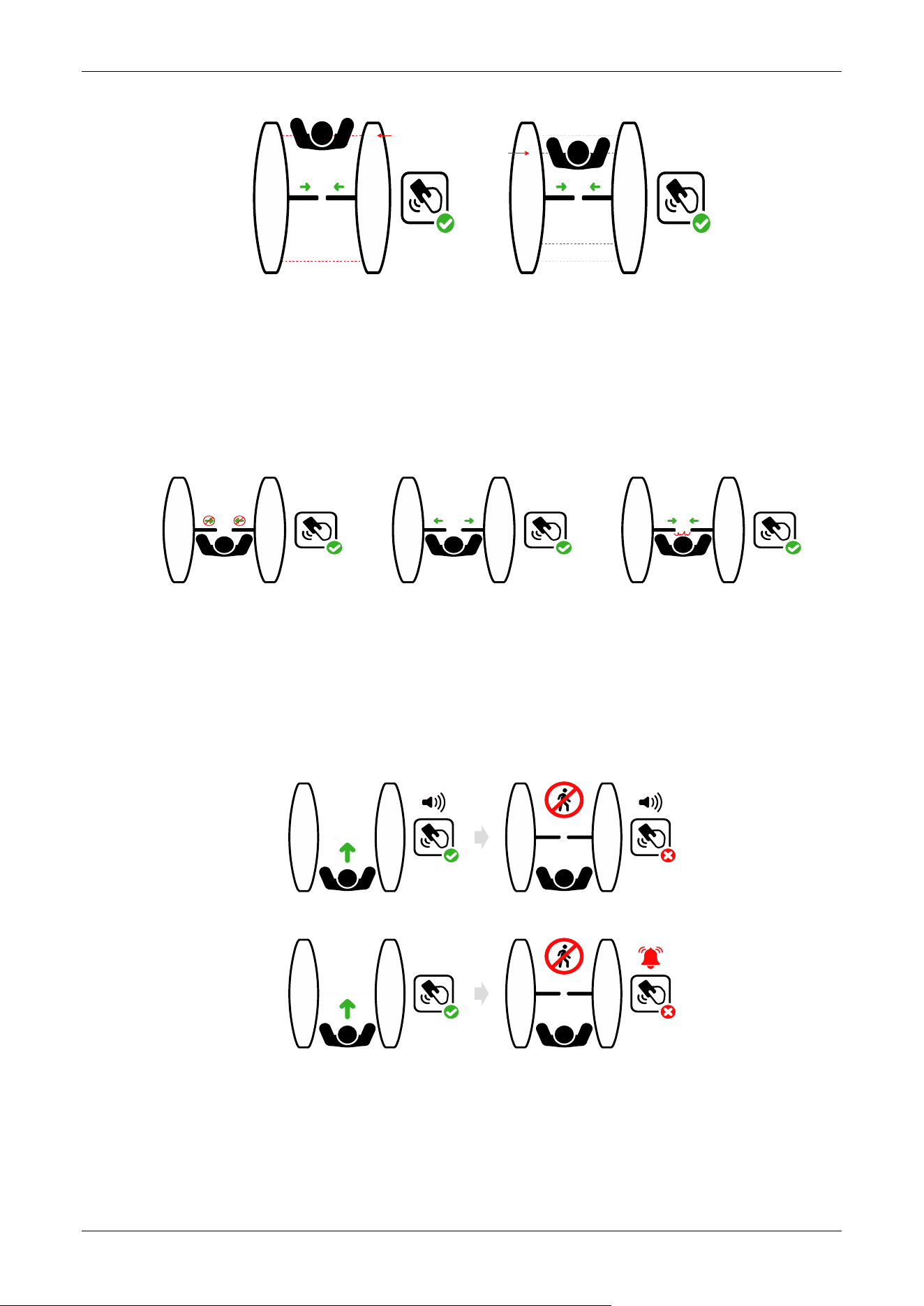
28EXXX : Gate Closing Position
The Gate Closing Position (28E001) will only be effective when the Anti-pinch Area Setting is set to
(21E001).
28E000: Last pair (Default)
28E001: Penultimate pair (Anti-tailgating)
Saturn-S1000 Pro Series User Manual
Page | 49 Copyright©2026 ZKTECO CO., LTD. All Rights Reserved.
RFID
RFID
Last IR
Penultimate IR
29EXXX : Anti-pinch Action Setting
29E000: Stop
29E001: Open (Default)
29E002: Close the function
RFID RFID RFID
Stop Open
Not A nti- pinc h
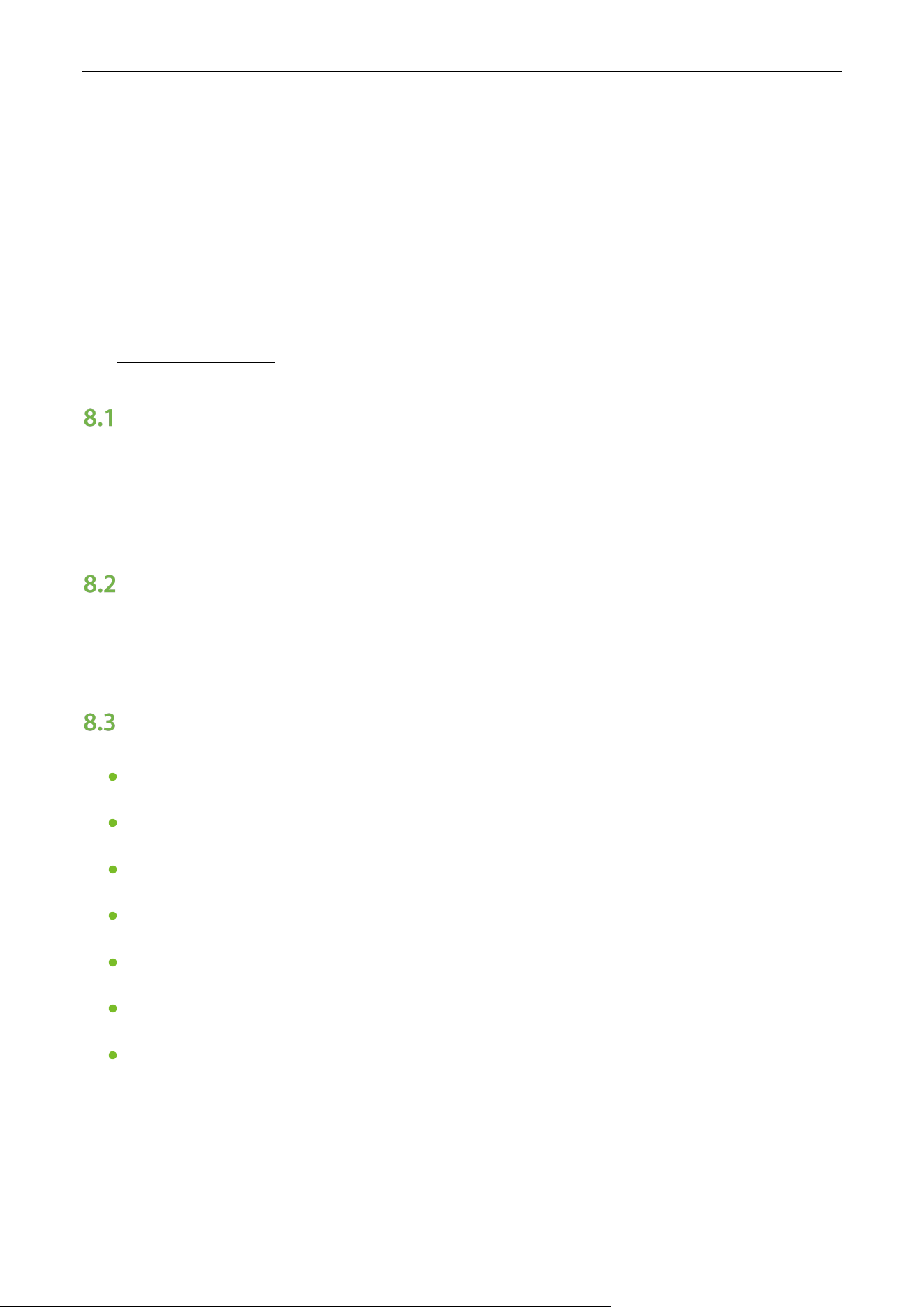
30EXXX : Voice Switching
Sets whether the device announces a voice or an alarm tone.
30E000: Voice playback
30E001: Alarm tone (Default)
NO ENTR Y
NO ENTR Y
30E00 0
30E00 1
RFID RFID
RFID RFID
31EXXX : Movement Replacement
31E000: Swing Barrier A

Saturn-S1000 Pro Series User Manual
Page | 50 Copyright©2026 ZKTECO CO., LTD. All Rights Reserved.
31E001: Swing Barrier B (Default)
31E002: AA (Wing Gate)
31E003: BB (Wing Gate)
31E004: AB (Wing Gate)
31E005: BA (Wing Gate)
32EXXX : Swing Arm Selection
32E000: Normal Swing Arm (Default)
32E001: High Swing Arm
33EXXX : Main Device Opening Compensation Speed
A larger number results in faster compensation speed. The Main Device Compensation Speed can
be set between 30 and 200, with a default value of 100.
34EXXX : Main Device Closing Compensation Speed
A larger number results in faster compensation speed. The Main Device Closing Compensation
Speed can be set between 30 and 200, with a default value of 100 (standard speed for general use).
35EXXX : New and Old Motherboards
The New and Old Motherboards can be set between 30 and 200, with a default value of 102.
36EXXX : Right Direction Voice
Selects the voice prompt for right-direction passage. Valid values are 0 to 21, with a default value
of 0 (silent — no voice output).
37EXXX : Left Direction Voice
Selects the voice prompt for left-direction passage. Valid values are 0 to 21, with a default value of
17 (default voice prompt).
Note: By default, voice prompts are output only from the left side. To enable voice on the right side,
set 36EXXX to a value between 1 and 21.
38EXXX : Locking Force Adjustment
Saturn-S1000 Pro Series User Manual
Page | 51 Copyright©2026 ZKTECO CO., LTD. All Rights Reserved.
Valid values are 1 to 10 and the default value is 5. A larger number results in stronger resistance
against forced pushing the barrier.
39EXXX : Motor Parameter Settings
Valid values are 0 to 4, and the default value is 3.
8 Maintenance
Chassis Maintenance
The chassis is made up of cold-rolled SPCC steel (GB700). If it is used for substantial period, then
there may be rust stains on its surface. Regularly clean the surface with a clean cloth carefully. Coat
the surface with anti-rust oil and do not cover the infrared sensor.
Movement Maintenance
Before doing maintenance, turn off the power. Open the door, wipe the surface dust, and apply
lubricant for smooth movement.
Power Supply Maintenance
Switch off the power supply before maintenance.
Check the power plug connection, if found loose, fix it properly.
Do not change any connection position randomly.
Check the external power supply insulation periodically.
Do periodic check for any kind of leakage.
Check if the technical parameters of interface are normal.
Check the service life of the electronic components and replace accordingly.
Caution: All the above-mentioned maintenance methods for swing barrier must be carried out by a
professional technician, especially the movement and the electric control part. For ensuring operational
safety, first switch off the power supply when the barrier is not in use. Perform the safety check on a
weekly basis to ensure that the turnstile is safe and ready for user operation.

Saturn-S1000 Pro Series User Manual
Page | 52 Copyright©2026 ZKTECO CO., LTD. All Rights Reserved.
9 Troubleshooting
No. Failure Descriptions Analysis and Solution
1
The mode indicator light does not
respond or the indication is
incorrect.
Check that the control panel mode indicator wiring
is correct and verify all contacts are secure.
2
After swiping the card, there is only a
speed gate unlocked.
Check the mode setting of the main and sub
devices and inspect the 8-core, 2-core connection
cables. Refer to the wiring diagram for the correct
circuit configuration.
3
The barrier doesn’t close when the
opening delay time is ended.
Check whether the opening delay time is too long
or whether the IR sensor is covered.
4
When the gate is self-tested, the
swing arm is not in the normal
closing position!
An obstacle is present in the lane during self-test.
Remove all obstructions, then power-cycle the unit
to restart the self-test.
Saturn-S1000 Pro Series User Manual
Page | 53 Copyright©2026 ZKTECO CO., LTD. All Rights Reserved.
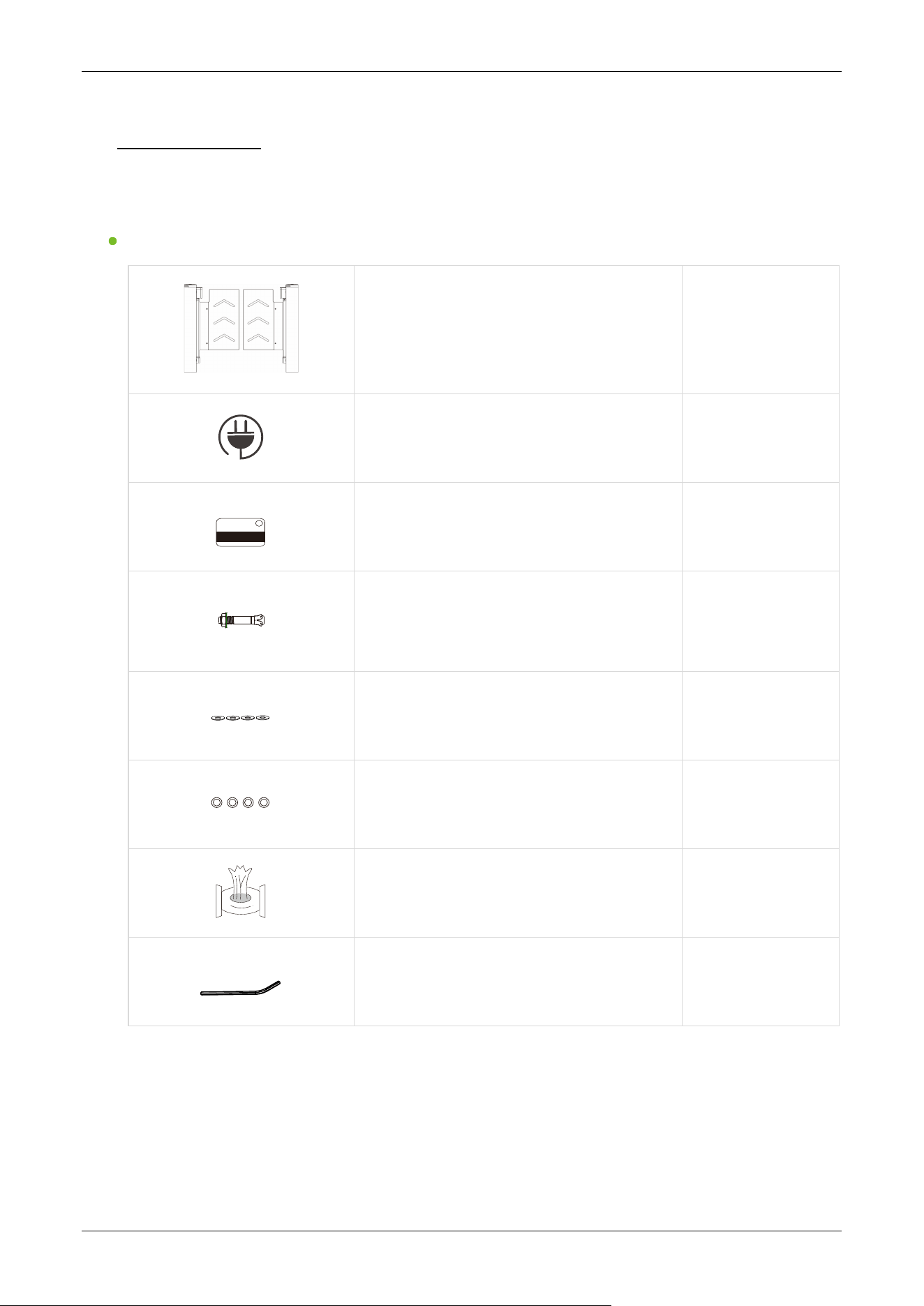
10 Packing List
The package consists of the following items:
Saturn-S1000 Pro:
Saturn-S1000 Pro (Main and Sub)
2
Power Cable
1
Card
1
Expansion Screw M12*100
8
Washer
8
Expansion Screw Washers
8
Stainless Steel Maintenance Wipes
1
Hex Wrench
1
Saturn-S1000 Pro Series User Manual
Page | 54 Copyright©2026 ZKTECO CO., LTD. All Rights Reserved.
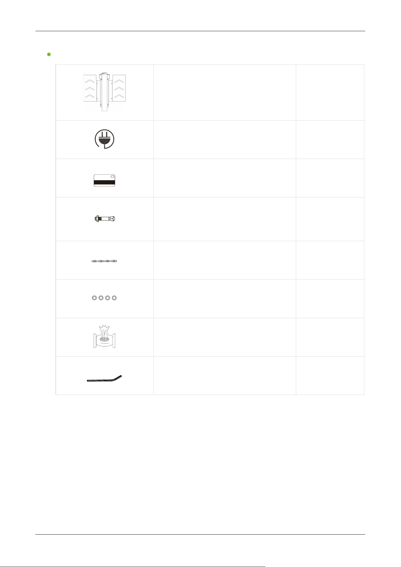
Saturn-S1200 Pro:
Saturn-S1200 Pro
1
Power Cable
1
Card
1
Expansion Screw M12*100
4
Washer
4
Expansion Screw Washers
4
Stainless Steel Maintenance Wipes
1
Hex Wrench
1

Saturn-S1000 Pro Series User Manual
Page | 55 Copyright©2026 ZKTECO CO., LTD. All Rights Reserved.
Revision History
Revision Date Author Reviewer Description
V1.0 07/24/2026 Mia Liang Original Document

ZKTeco Industrial Park, No. 32, Industrial Road,
Tangxia Town, Dongguan, China.
Phone : +86 769 - 82109991
Fax : +86 755 - 89602394
www.zkteco.com
Copyright © 2026 ZKTECO CO., LTD. All Rights Reserved.