Product Name and Model Number User Manual
P a g e | 1 Copyright©2020 ZKTECO CO., LTD. All rights reserved.
Thank you for choosing our product. Please read the instructions carefully
before operation. Follow these instructions to ensure that the product is
functioning properly. The images shown in this manual are for illustrative
purposes only.
For further details, please visit our Company’s website
www.zkteco.com.

F34 User Manual
P a g e | 1 Copyright © 2026 ZKTECO CO., LTD. All rights reserved.
Copyright © 2026 ZKTECO CO., LTD. All rights reserved.
Without the prior written consent of ZKTeco, no portion of this manual can be copied or forwarded in any
way or form. All parts of this manual belong to ZKTeco and its subsidiaries (hereinafter the "Company" or
"ZKTeco").
Trademark
is a registered trademark of ZKTeco. Other trademarks involved in this manual are owned by
their respective owners.
Disclaimer
This manual contains information on the operation and maintenance of the ZKTeco equipment. The
copyright in all the documents, drawings, etc. in relation to the ZKTeco supplied equipment vests in and is
the property of ZKTeco. The contents hereof should not be used or shared by the receiver with any third
party without express written permission of ZKTeco.
The contents of this manual must be read as a whole before starting the operation and maintenance of the
supplied equipment. If any of the content(s) of the manual seems unclear or incomplete, please contact
ZKTeco before starting the operation and maintenance of the said equipment.
It is an essential pre-requisite for the satisfactory operation and maintenance that the operating and
maintenance personnel are fully familiar with the design and that the said personnel have received
thorough training in operating and maintaining the machine/unit/equipment. It is further essential for the
safe operation of the machine/unit/equipment that personnel has read, understood and followed the
safety instructions contained in the manual.
In case of any conflict between terms and conditions of this manual and the contract specifications,
drawings, instruction sheets or any other contract-related documents, the contract conditions/documents
shall prevail. The contract specific conditions/documents shall apply in priority.
ZKTeco offers no warranty, guarantee or representation regarding the completeness of any information
contained in this manual or any of the amendments made thereto. ZKTeco does not extend the warranty
of any kind, including, without limitation, any warranty of design, merchantability or fitness for a particular
purpose.
ZKTeco does not assume responsibility for any errors or omissions in the information or documents which
are referenced by or linked to this manual. The entire risk as to the results and performance obtained from
using the information is assumed by the user.
ZKTeco in no event shall be liable to the user or any third party for any incidental, consequential, indirect,
special, or exemplary damages, including, without limitation, loss of business, loss of profits, business
interruption, loss of business information or any pecuniary loss, arising out of, in connection with, or

F34 User Manual
P a g e | 2 Copyright © 2026 ZKTECO CO., LTD. All rights reserved.
relating to the use of the information contained in or referenced by this manual, even if ZKTeco has been
advised of the possibility of such damages.
This manual and the information contained therein may include technical, other inaccuracies or
typographical errors. ZKTeco periodically changes the information herein which will be incorporated into
new additions/amendments to the manual. ZKTeco reserves the right to add, delete, amend or modify the
information contained in the manual from time to time in the form of circulars, letters, notes, etc. for better
operation and safety of the machine/unit/equipment. The said additions or amendments are meant for
improvement /better operations of the machine/unit/equipment and such amendments shall not give any
right to claim any compensation or damages under any circumstances.
ZKTeco shall in no way be responsible (i) in case the machine/unit/equipment malfunctions due to any
non-compliance of the instructions contained in this manual (ii) in case of operation of the
machine/unit/equipment beyond the rate limits (iii) in case of operation of the machine and equipment in
conditions different from the prescribed conditions of the manual.
The product will be updated from time to time without prior notice. The latest operation procedures and
relevant documents are available on http://www.zkteco.com
If there is any issue related to the product, please contact us.
ZKTeco Headquarters
Address ZKTeco Industrial Park, No. 32, Industrial Road,
Tangxia Town, Dongguan, China.
Phone +86 769 - 82109991
Fax +86 755 - 89602394
For business related queries, please write to us at: sales@zkteco.com.
To know more about our global branches, visit www.zkteco.com.

F34 User Manual
P a g e | 3 Copyright © 2026 ZKTECO CO., LTD. All rights reserved.
About the Company
ZKTeco is one of the world’s largest manufacturer of RFID and Biometric (Fingerprint, Facial, Finger-vein)
readers. Product offerings include Access Control readers and panels, Near & Far-range Facial Recognition
Cameras, Elevator/floor access controllers, Turnstiles, License Plate Recognition (LPR) gate controllers and
Consumer products including battery-operated fingerprint and face-reader Door Locks. Our security
solutions are multi-lingual and localized in over 18 different languages. At the ZKTeco state-of-the-art
700,000 square foot ISO9001-certified manufacturing facility, we control manufacturing, product design,
component assembly, and logistics/shipping, all under one roof.
The founders of ZKTeco have been determined for independent research and development of biometric
verification procedures and the productization of biometric verification SDK, which was initially widely
applied in PC security and identity authentication fields. With the continuous enhancement of the
development and plenty of market applications, the team has gradually constructed an identity
authentication ecosystem and smart security ecosystem, which are based on biometric verification
techniques. With years of experience in the industrialization of biometric verifications, ZKTeco was
officially established in 2007 and now has been one of the globally leading enterprises in the biometric
verification industry owning various patents and being selected as the National High-tech Enterprise for 6
consecutive years. Its products are protected by intellectual property rights.
About the Manual
This manual introduces the operations of F34.
All figures displayed are for illustration purposes only. Figures in this manual may not be exactly consistent
with the actual products.
Features and parameters with ★ are not available in all devices.
F34 User Manual
P a g e | 4 Copyright © 2026 ZKTECO CO., LTD. All rights reserved.
Document Conventions
Conventions used in this manual are listed below:
GUI Conventions
For Software
Convention
Description
Bold font
Used to identify software interface names e.g. OK, Confirm, Cancel.
>
Multi-level menus are separated by these brackets. For example, File > Create >
Folder.
For Device
Convention
Description
< >
Button or key names for devices. For example, press <OK>.
[ ]
Window names, menu items, data table, and field names are inside square
brackets. For example, pop up the [New User] window.
/
Multi-level menus are separated by forwarding slashes. For example,
[File/Create/Folder].
Symbols
Convention
Description
This represents a note that needs to pay more attention to.
The general information which helps in performing the operations faster.
The information which is significant.
Care taken to avoid danger or mistakes.
The statement or event that warns of something or that serves as a cautionary
example.

F34 User Manual
P a g e | 5 Copyright © 2026 ZKTECO CO., LTD. All rights reserved.
Table of Contents
1 SAFETY MEASURES....................................................................................................................................9
2 ELECTRICAL SAFETY................................................................................................................................ 10
3 OPERATION SAFETY ................................................................................................................................ 10
4 INSTRUCTION FOR USE ............................................................................................................................11
4.1 Finger Positioning...........................................................................................................................................................................................11
4.2 Standby Interface ............................................................................................................................................................................................ 11
4.3 Verification Mode............................................................................................................................................................................................ 14
4.3.1 Fingerprint Verification..................................................................................................................................................................................................14
4.3.2 Card Verification................................................................................................................................................................................................................15
4.3.3 Password Verification..................................................................................................................................................................................................... 16
4.3.4 QR Code Verification★ (PUSH Protocol)................................................................................................................................................................17
4.3.5 Combined Verification (PUSH Protocol)................................................................................................................................................................. 17
5 MAIN MENU..............................................................................................................................................19
6 USER MANAGEMENT............................................................................................................................... 21
6.1 New User Registration (PUSH Protocol) .................................................................................................................................................21
6.1.1 Register a User ID and Name....................................................................................................................................................................................... 21
6.1.2 User Role...............................................................................................................................................................................................................................22
6.1.3 Register Fingerprint.........................................................................................................................................................................................................22
6.1.4 Card Number......................................................................................................................................................................................................................23
6.1.5 Password.............................................................................................................................................................................................................................. 23
6.1.6 Access Control Role......................................................................................................................................................................................................... 23
6.2 All Users............................................................................................................................................................................................................... 24
6.2.1 Edit User (PUSH Protocol)............................................................................................................................................................................................. 24
6.2.2 Delete User (PUSH Protocol)........................................................................................................................................................................................25
6.3 Display Style.......................................................................................................................................................................................................25
7 USER ROLE (PUSH PROTOCOL) ............................................................................................................... 27
8 COMMUNICATION................................................................................................................................... 29
8.1 Ethernet...............................................................................................................................................................................................................29
8.2 Serial Comm .......................................................................................................................................................................................................30
8.3 PC Connection (PUSH Protocol)................................................................................................................................................................31
8.4 Cellular Data Network★...............................................................................................................................................................................31
8.5 Wi-Fi Settings★................................................................................................................................................................................................33
8.6 Cloud Server Settings.....................................................................................................................................................................................35
8.7 Wiegand Setup.................................................................................................................................................................................................36
8.7.1 Wiegand Input...................................................................................................................................................................................................................36
8.7.2 Wiegand Output............................................................................................................................................................................................................... 38
8.8 Network Diagnosis..........................................................................................................................................................................................39
9 SYSTEM SETTINGS ................................................................................................................................... 40
9.1 Date and Time...................................................................................................................................................................................................40
9.2 Access Logs Settings / Attendance ..........................................................................................................................................................41
9.3 Fingerprint..........................................................................................................................................................................................................42
9.4 Device Type Settings......................................................................................................................................................................................44

F34 User Manual
P a g e | 6 Copyright © 2026 ZKTECO CO., LTD. All rights reserved.
9.5 Security Settings .............................................................................................................................................................................................. 44
9.6 USB Upgrade ..................................................................................................................................................................................................... 45
9.7 Update Firmware Online..............................................................................................................................................................................45
9.8 Factory Reset..................................................................................................................................................................................................... 46
10 PERSONALIZE SETTINGS....................................................................................................................... 47
10.1 User Interface ..................................................................................................................................................................................................47
10.2 Voice................................................................................................................................................................................................................... 48
10.3 Bell Schedules.................................................................................................................................................................................................48
10.4 Punch States Options (T&A PUSH).........................................................................................................................................................49
10.5 Shortcut Key Mappings (T&A PUSH) .....................................................................................................................................................50
11 DATA MANAGEMENT (PUSH PROTOCOL)........................................................................................... 53
12 INTERCOM .............................................................................................................................................. 55
12.1 SIP Settings........................................................................................................................................................................................................55
12.1.1 Local Settings...................................................................................................................................................................................................................55
12.1.2 Audio Options..................................................................................................................................................................................................................56
12.1.3 Video Options..................................................................................................................................................................................................................57
12.1.4 Call Options...................................................................................................................................................................................................................... 57
12.1.5 Contact List.......................................................................................................................................................................................................................58
12.1.6 Calling Shortcut Settings............................................................................................................................................................................................ 59
12.1.7 Advanced Settings.........................................................................................................................................................................................................60
12.2 Doorbell Setting..............................................................................................................................................................................................61
12.3 ONVIF Settings.................................................................................................................................................................................................61
13 WORK CODE (T&A PUSH) ...................................................................................................................... 64
13.1 Add a Work Code...........................................................................................................................................................................................64
13.2 All Work Codes............................................................................................................................................................................................... 64
13.3 Work Code Options......................................................................................................................................................................................65
14 ACCESS CONTROL..................................................................................................................................66
14.1 Access Control Options................................................................................................................................................................................67
14.2 Time Rule Settings / Time Schedule (PUSH Protocol)........................................................................................................................71
14.3 Holidays (PUSH Protocol).............................................................................................................................................................................72
14.4 Access Groups (T&A PUSH)..........................................................................................................................................................................73
14.5 Combined Verification (PUSH Protocol)................................................................................................................................................. 74
14.6 Anti-passback Setup (PUSH Protocol)..................................................................................................................................................... 75
14.7 Duress Options Settings (PUSH Protocol)..............................................................................................................................................76
15 USB MANAGER .......................................................................................................................................78
15.1 USB Download (PUSH Protocol)................................................................................................................................................................78
15.2 USB Upload.......................................................................................................................................................................................................79
15.3 Download Options (T&A PUSH)..............................................................................................................................................................80
16 ATTENDANCE SEARCH .......................................................................................................................... 81
17 AUTOTEST .............................................................................................................................................. 82
18 SYSTEM INFORMATION.........................................................................................................................83
19 CONNECT TO WEBSERVER.................................................................................................................... 84
19.1 Login Webserver............................................................................................................................................................................................84
19.1.1 Standard Mode................................................................................................................................................................................................................84

F34 User Manual
P a g e | 7 Copyright © 2026 ZKTECO CO., LTD. All rights reserved.
19.1.2 AP Mode★........................................................................................................................................................................................................................85
19.2 Forgot Password............................................................................................................................................................................................86
19.3 Basic Information.......................................................................................................................................................................................... 88
19.4 System Information......................................................................................................................................................................................89
19.5 User Management........................................................................................................................................................................................ 91
19.5.1 User Registration............................................................................................................................................................................................................91
19.5.2 Search for Users.............................................................................................................................................................................................................. 93
19.5.3 Edit User............................................................................................................................................................................................................................. 93
19.5.4 Delete User........................................................................................................................................................................................................................94
19.6 Communication.............................................................................................................................................................................................95
19.6.1 Network Settings............................................................................................................................................................................................................95
19.6.2 Connection Settings..................................................................................................................................................................................................... 95
19.6.3 Cloud Service Setup......................................................................................................................................................................................................96
19.6.4 Serial Comm..................................................................................................................................................................................................................... 97
19.6.5 Wi-Fi Settings★..............................................................................................................................................................................................................97
19.6.6 Wiegand Setup................................................................................................................................................................................................................98
19.7 Personalize.......................................................................................................................................................................................................99
19.7.1 User Interface...................................................................................................................................................................................................................99
19.7.2 Voice..................................................................................................................................................................................................................................100
19.7.3 Punch State Options...................................................................................................................................................................................................100
19.8 System.............................................................................................................................................................................................................101
19.8.1 Date Setup......................................................................................................................................................................................................................101
19.8.2 Fingerprint......................................................................................................................................................................................................................102
19.8.3 Device Type Settings..................................................................................................................................................................................................103
19.8.4 Access Control Options.............................................................................................................................................................................................103
19.8.5 Access Logs Settings/Attendance........................................................................................................................................................................106
19.8.6 Security Settings.......................................................................................................................................................................................................... 107
19.8.7 Restore............................................................................................................................................................................................................................. 108
19.8.8 Restart...............................................................................................................................................................................................................................108
19.9 Device Management.................................................................................................................................................................................108
19.9.1 Device Data Management.......................................................................................................................................................................................108
19.9.2 Update Firmware.........................................................................................................................................................................................................109
19.9.3 Change Password........................................................................................................................................................................................................110
19.9.4 Operation Log...............................................................................................................................................................................................................110
19.9.5 Download Firmware Logs........................................................................................................................................................................................111
20 CONNECTING TO ZKBIO ZLINK APP ................................................................................................... 112
20.1 Login to the App.........................................................................................................................................................................................112
20.2 Add Device on the App............................................................................................................................................................................113
20.3 Set Access Levels........................................................................................................................................................................................ 114
20.4 Register Verification Mode on the App.............................................................................................................................................115
20.5 Video Intercom............................................................................................................................................................................................117
21 CONNECTING TO ZKBIO ZLINK WEB .................................................................................................. 119
21.1 Login to the Web ........................................................................................................................................................................................119
21.2 Add Device on the Web...........................................................................................................................................................................119

F34 User Manual
P a g e | 8 Copyright © 2026 ZKTECO CO., LTD. All rights reserved.
21.3 Set Access Levels........................................................................................................................................................................................ 121
21.4 Register Verification Mode on the Web............................................................................................................................................122
22 CONNECT TO ZKBIO CVACCESS SOFTWARE..................................................................................... 126
22.1 Set the Communication Address.........................................................................................................................................................126
22.2 Add Device on the Software..................................................................................................................................................................126
22.3 Add Personnel on the Software and Online Fingerprint Registration.................................................................................127
22.4 Mobile Credential★..................................................................................................................................................................................129
23 CONNECT TO ZKBIO TIME SOFTWARE............................................................................................... 132
23.1 Set the Communication Address.........................................................................................................................................................132
23.2 Add Device on the Software..................................................................................................................................................................132
23.3 Add Personnel on the Software and Online Fingerprint Registration.................................................................................133
24 CONNECT TO ZKBIO TIME CLOUD SOFTWARE..................................................................................135
24.1 Set the Communication Address.........................................................................................................................................................135
24.2 Add Device on the Software..................................................................................................................................................................135
24.3 Add Personnel on the Software and Online Fingerprint Registration.................................................................................136
25 CONNECTING TO WIRELESS DOORBELL★ ........................................................................................ 139
25.1 Connect the Wireless Doorbell.............................................................................................................................................................139
25.2 Unbinding the Wireless Doorbell........................................................................................................................................................ 139
26 SIP VIDEO INTERCOM..........................................................................................................................140
26.1 Local Area Network Use...........................................................................................................................................................................140
26.1.1 Call Contact List............................................................................................................................................................................................................145
26.1.2 Custom the Calling Shortcut Keys........................................................................................................................................................................146
26.1.3 Direct Calling.................................................................................................................................................................................................................146
26.2 SIP Server........................................................................................................................................................................................................147
26.2.1 SIP Server Configuration...........................................................................................................................................................................................148
26.2.2 Add Device..................................................................................................................................................................................................................... 151
26.2.3 Create Extension Numbers......................................................................................................................................................................................152
26.2.4 Contact List.....................................................................................................................................................................................................................153
26.2.5 Assignment of Extension Numbers and SIP Accounts................................................................................................................................ 155
26.2.6 PC Client Functionality..............................................................................................................................................................................................160
26.2.7 Make a Call......................................................................................................................................................................................................................163
APPENDIX 1...............................................................................................................................................169
Privacy Policy.........................................................................................................................................................................................................169
Eco-friendly Operation...................................................................................................................................................................................... 172

F34 User Manual
P a g e | 9 Copyright © 2026 ZKTECO CO., LTD. All rights reserved.
1 Safety Measures
The below instructions intend to ensure that the user can use the product correctly to avoid danger or
property loss. The following precautions are to keep users safe and prevent any damage. Please read
carefully before installation.
Noncompliance with instructions could lead to product damage or physical injury (may even cause
death).
1. Read, follow, and retain instructions - All safety and operational instructions must be properly
read and followed before bringing the device into service.
2. Do not ignore warnings - Adhere to all warnings on the unit and in the operating instructions.
3. Accessories - Use only manufacturer-recommended or product-sold accessories. Please do not use
any other components other than manufacturer suggested materials.
4. Precautions for the installation – Do not place this device on an unstable stand or frame. It may
fall and cause serious injury to persons and damage to the device.
5. Service - Do not try to service this unit yourself. Opening or removing covers may expose you to
hazardous voltages or other hazards.
6. Damage requiring service - Disconnect the system from the Mains AC or DC power source and
refer service personnel under the following conditions:
When cord or connection control is affected.
When the liquid spilled, or an item dropped into the system.
If the system is exposed to water or inclement weather conditions (rain, snow, and more).
If the system is not operating normally, under operating instructions.
Just change controls defined in operating instructions. Improper adjustment of the controls may
result in damage and involve a qualified technician to return the device to normal operation.
And do not connect multiple devices to one power adapter as adapter overload can cause over-
heat or fire hazard.
7. Replacement parts - When replacement parts are required, service technicians must only use
replacement parts provided by the supplier. Unauthorized substitutes can result in a burn, shock,
or other hazards.
8. Safety check - On completion of service or repair work on the unit, ask the service technician to
perform safety checks to ensure proper operation of the device.
9. Power sources - Operate the system only from the label's power source form. If the sort of power
supply to use is unclear, call your dealer.
10. Lightning - Can install external lightning conductors to protect against electrical storms. It stops
power-ups from destroying the system.
Recommended installing the devices in areas with limited access.

F34 User Manual
P a g e | 10 Copyright © 2026 ZKTECO CO., LTD. All rights reserved.
2 Electrical Safety
Before connecting an external cable to the device, complete grounding properly, and set up surge
protection; otherwise, static electricity will damage the mainboard.
Make sure that the power has been disconnected before you wire, install, or dismantle the device.
Ensure that the signal connected to the device is a weak-current (switch) signal; otherwise,
components of the device will get damaged.
Ensure that the standard voltage applicable in your country or region is applied. If you are not sure
about the endorsed standard voltage, please consult your local electric power company. Power
mismatch may cause a short circuit or device damage.
In the case of power supply damage, return the device to the professional technical personnel or
your dealer for handling.
To avoid interference, keep the device far from high electromagnetic radiation devices, such as
generators (including electric generators), radios, televisions, (especially CRT) monitors, or speakers.
3 Operation Safety
If smoke, odour, or noise rise from the device, turn off the power at once and unplug the power
cable, and then please contact the service centre.
Transportation and other unpredictable causes may damage the device hardware. Check whether
the device has any intense damage before installation.
If the device has major defects that you cannot solve, contact your dealer as soon as possible.
Dust, moisture, and abrupt temperature changes can affect the device's service life. You are
advised not to keep the device under such conditions.
Do not keep the device in a place that vibrates. Handle the device with care. Do not place heavy
objects on top of the device.
Do not apply rosin, alcohol, benzene, pesticides, and other volatile substances that may damage
the device enclosure. Clean the device accessories with a piece of soft cloth or a small amount of
cleaning agent.
If you have any technical questions regarding usage, contact certified or experienced technical
personnel.
Note:
Make sure whether the positive polarity and negative polarity of the DC 12V power supply is
connected correctly. A reverse connection may damage the device. It is not advisable to connect
the AC 24V power supply to the DC 12V input port.
Make sure to connect the wires following the positive polarity and negative polarity shown on the
device's nameplate.
The warranty service does not cover accidental damage, damage caused by mis-operation, and
damage due to independent installation or repair of the product by the user.
F34 User Manual
P a g e | 11 Copyright © 2026 ZKTECO CO., LTD. All rights reserved.
4 Instruction for Use
Before getting into the device features and functions, it is recommended to be familiar with the below
fundamentals.
4.1 Finger Positioning
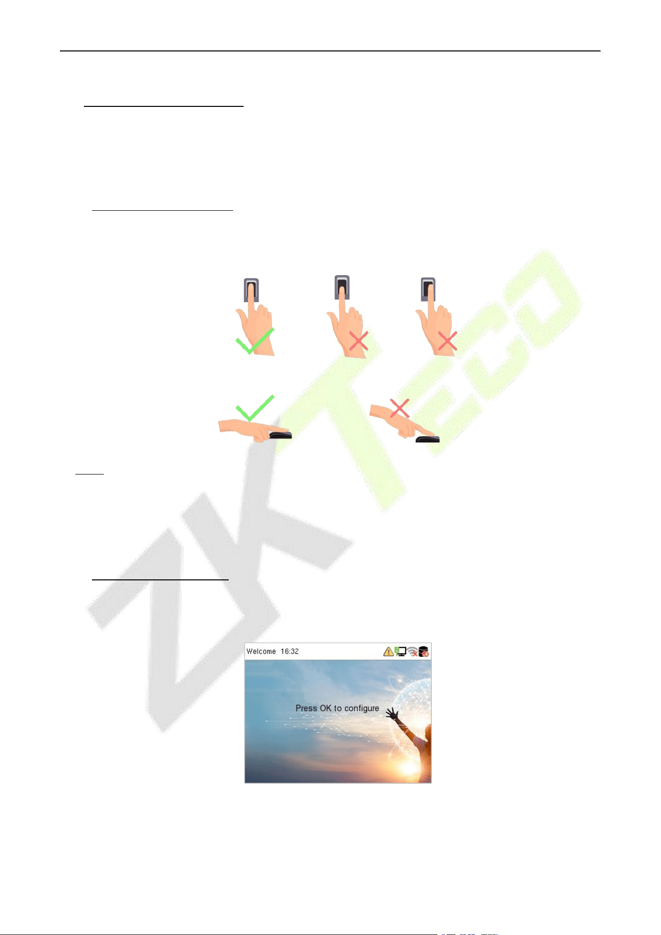
Recommended fingers: The index, middle, or ring finger and avoid using the thumb or pinky fingers,
as they are difficult to accurately press onto the fingerprint reader.
Note: Please use the correct method when pressing your fingers onto the fingerprint reader for
registration and identification. Our company will assume no liability for recognition issues that may
result from incorrect usage of the product. We reserve the right of final interpretation and modification
concerning this point.
4.2 Standby Interface
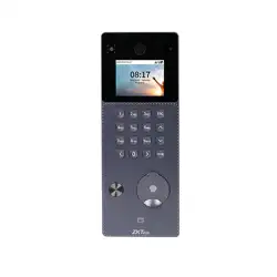
The device uses a 2.4-inch color screen, which all operations are performed through the keypad. After
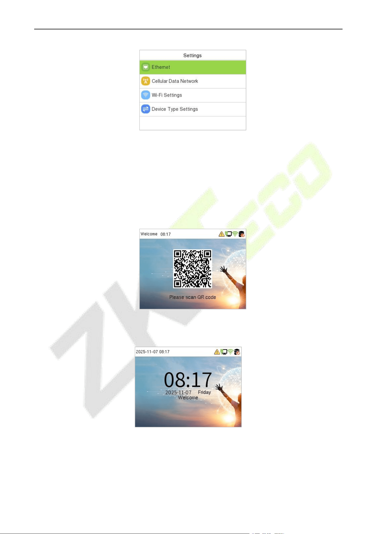
connecting the power supply for the first time, the following standby interface is displayed:
Press M/OK to enter the Settings interface:
Too low
Too close to the edge
Vertical
F34 User Manual
P a g e | 12 Copyright © 2026 ZKTECO CO., LTD. All rights reserved.
The device type is BEST Protocol by default. You can enter Device Type Settings to switch the
communication protocol as needed.
BEST Protocol: It is suitable for connecting to ZKBio Zlink.
PUSH Protocol: It can be set as A&C PUSH (which is suitable for connecting to ZKBio CVAccess) or
T&A PUSH (which is suitable for connecting to ZKBio Time Cloud/ZKBio Time).
Enter Ethernet or Wi-Fi Settings to configure the network. After setting successfully, the device will
pop up a QR code interface for scanning.
Once the device is connected to ZKBio Zlink, the QR code will disappear. Or the device type is switched
to PUSH Protocol, the following standby interface is displayed:
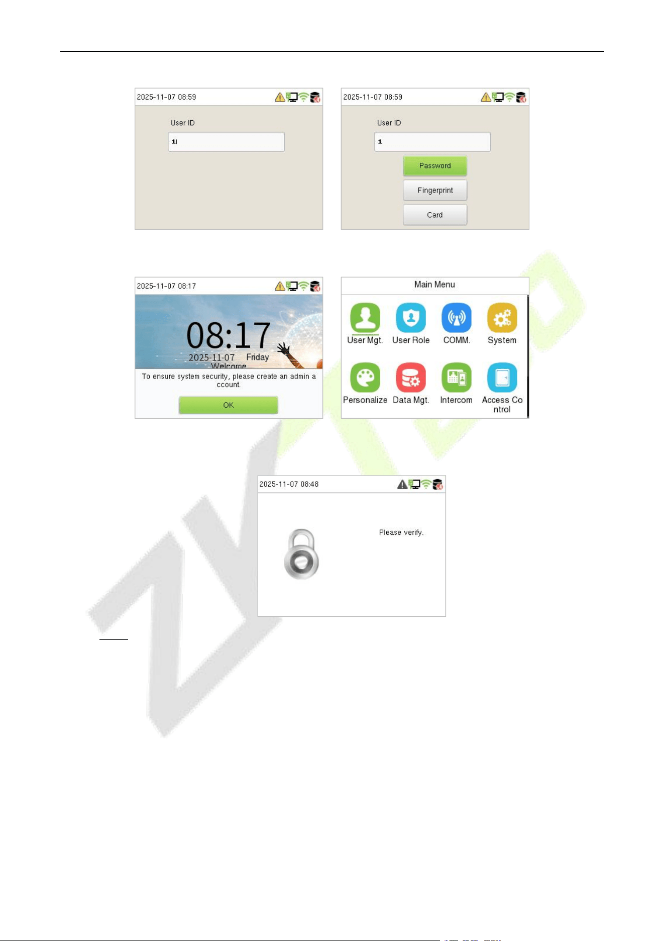
Enter any number to access the User ID input interface.
F34 User Manual
P a g e | 13 Copyright © 2026 ZKTECO CO., LTD. All rights reserved.
When there is no Super Administrator set in the device, press M/OK to go to the menu.
After adding a Super Administrator on the device, it requires the Super Administrator’s verification
before opening the menu functions.
Note: For the security of the device, it is recommended to register a super administrator the first
time you use the device.
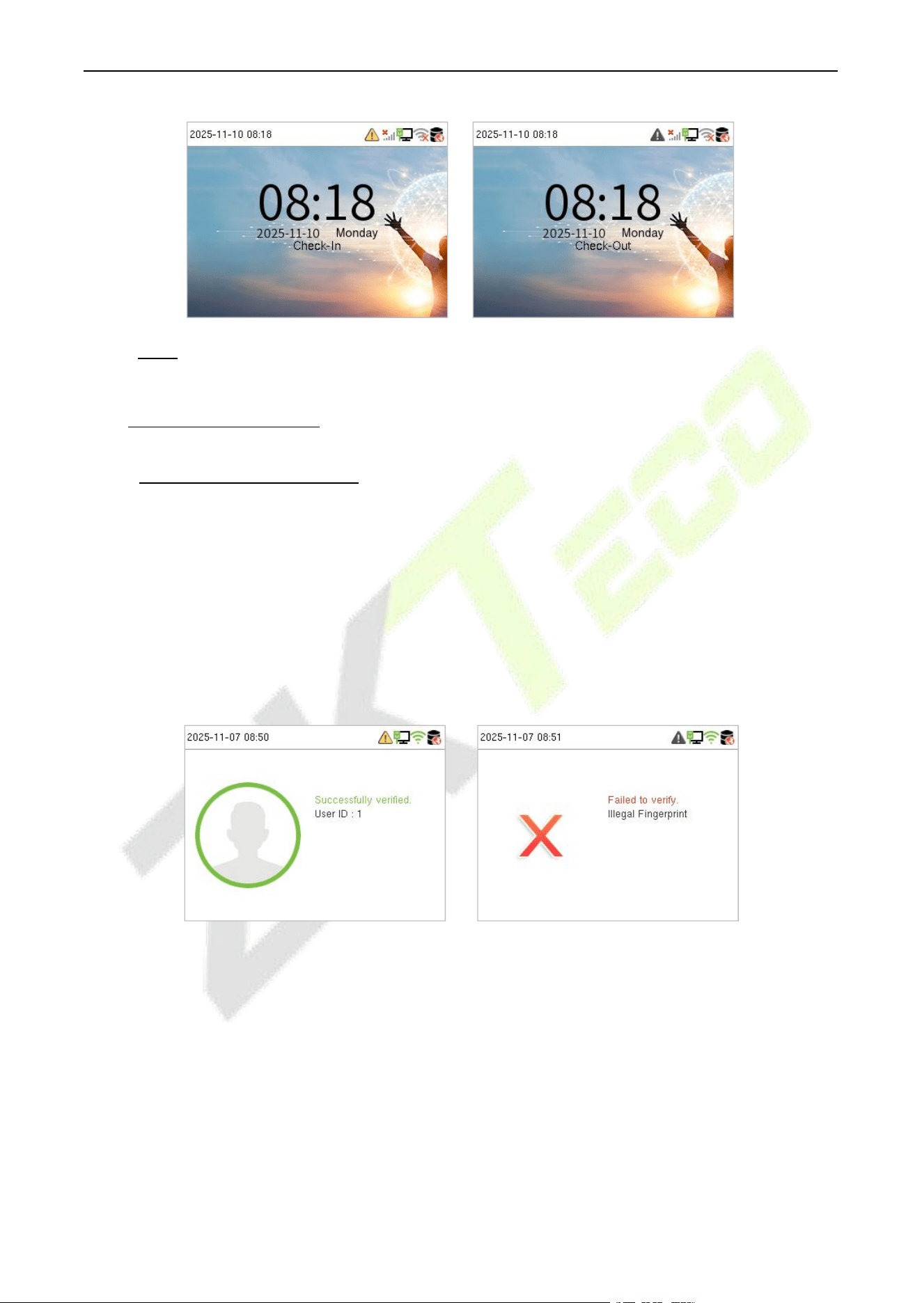
On the standby interface, the punch state options can also be shown and used directly. The black
bold shortcut key mappings will be displayed on the screen if you press the relevant shortcut key on
the keypad, as shown in the picture below. For the specific operation method, please see "Shortcut
Key Mappings."
F34 User Manual
P a g e | 14 Copyright © 2026 ZKTECO CO., LTD. All rights reserved.
Note: The punch state options are only available when the device type is set as T&A PUSH.
4.3 Verification Mode
4.3.1 Fingerprint Verification
1: N Fingerprint Verification Mode
The device compares the current fingerprint with the available fingerprint data stored in its database.
Fingerprint authentication mode is activated when a user places their finger onto the fingerprint
scanner.
Please follow the recommended way to place your finger onto the sensor. For details, refer to section
Finger Positioning.
Verification is successful: Verification is failed:
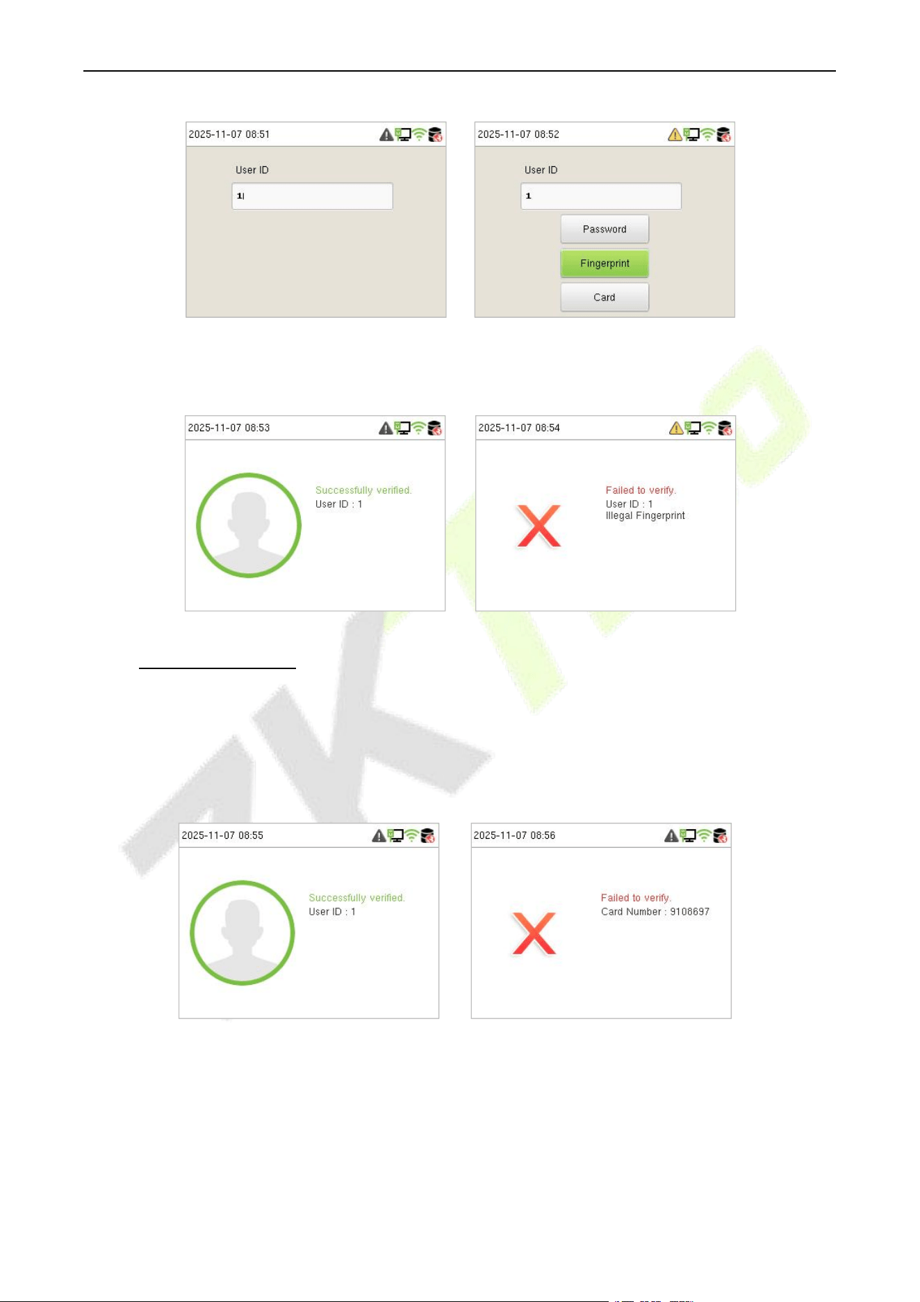
1:1 Fingerprint Verification Mode
The device compares the current fingerprint with the fingerprints linked to the entered User ID through
the virtual keyboard.
In case users are unable to gain access using the 1:N authentication method, they can attempt to verify
their identity using the 1:1 verification mode.
Enter the user ID and press M/OK. If an employee registers a password and card in addition to the
fingerprint, the following screen will appear. Select Fingerprint to enter the 1:1 fingerprint verification
mode.
F34 User Manual
P a g e | 15 Copyright © 2026 ZKTECO CO., LTD. All rights reserved.
Press the fingerprint to verify.
Verification is successful: Verification is failed:
4.3.2 Card Verification
1: N Card Verification Mode
The 1: N Card Verification Mode compares the card number in the card induction area with all the card
number data registered in the device. The following screen displays on the card verification screen.
Verification is successful: Verification is failed:
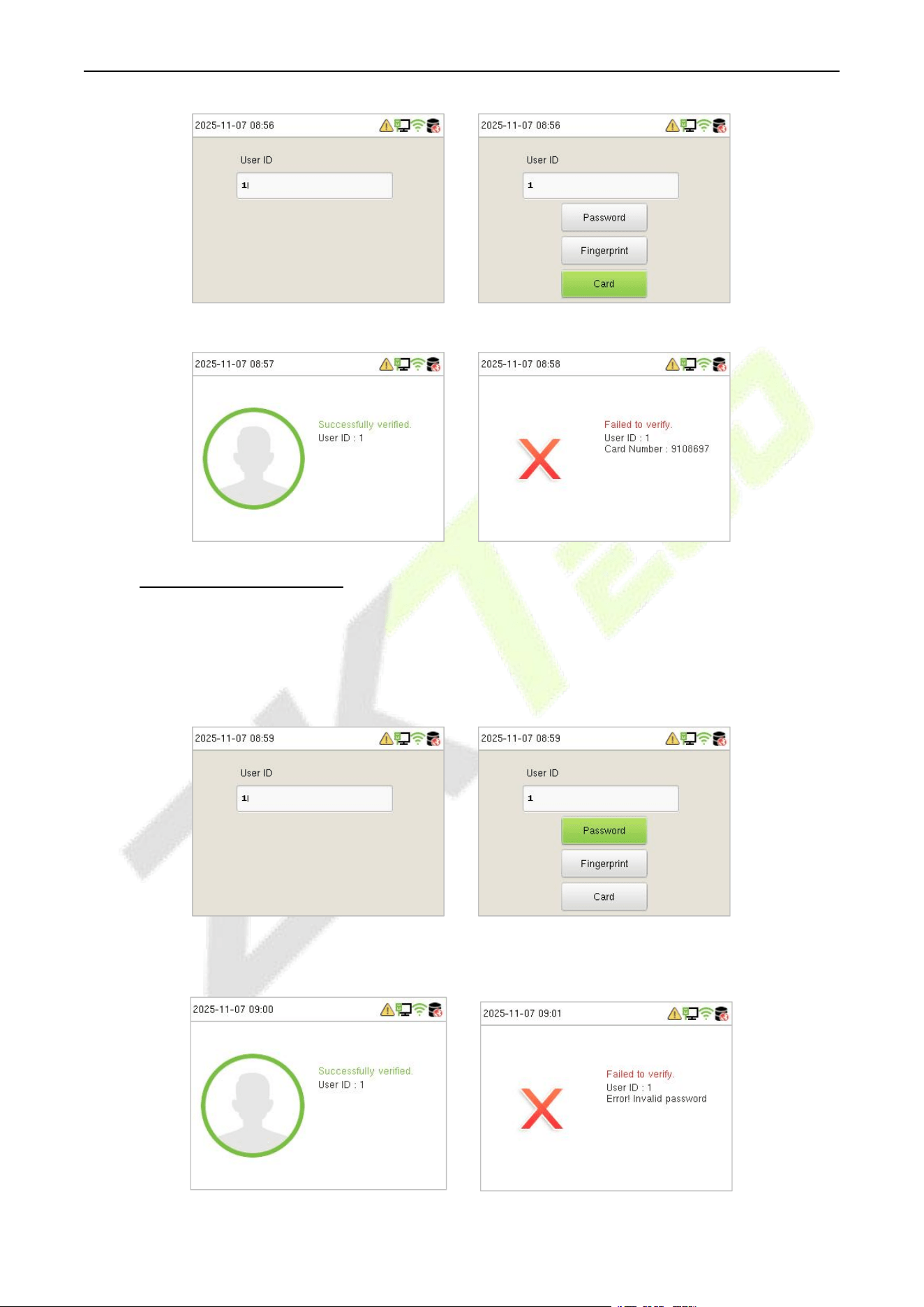
1:1 Card Verification Mode
The 1:1 Card Verification mode compares the card number in the card induction area with the number
associated with the employee's User ID registered in the device.
Enter the user ID and press M/OK. If an employee registers a fingerprint and password in addition to
the card, the following screen will appear. Select Card to enter the 1:1 card verification mode.
F34 User Manual
P a g e | 16 Copyright © 2026 ZKTECO CO., LTD. All rights reserved.
Verification is successful: Verification is failed:
4.3.3 Password Verification
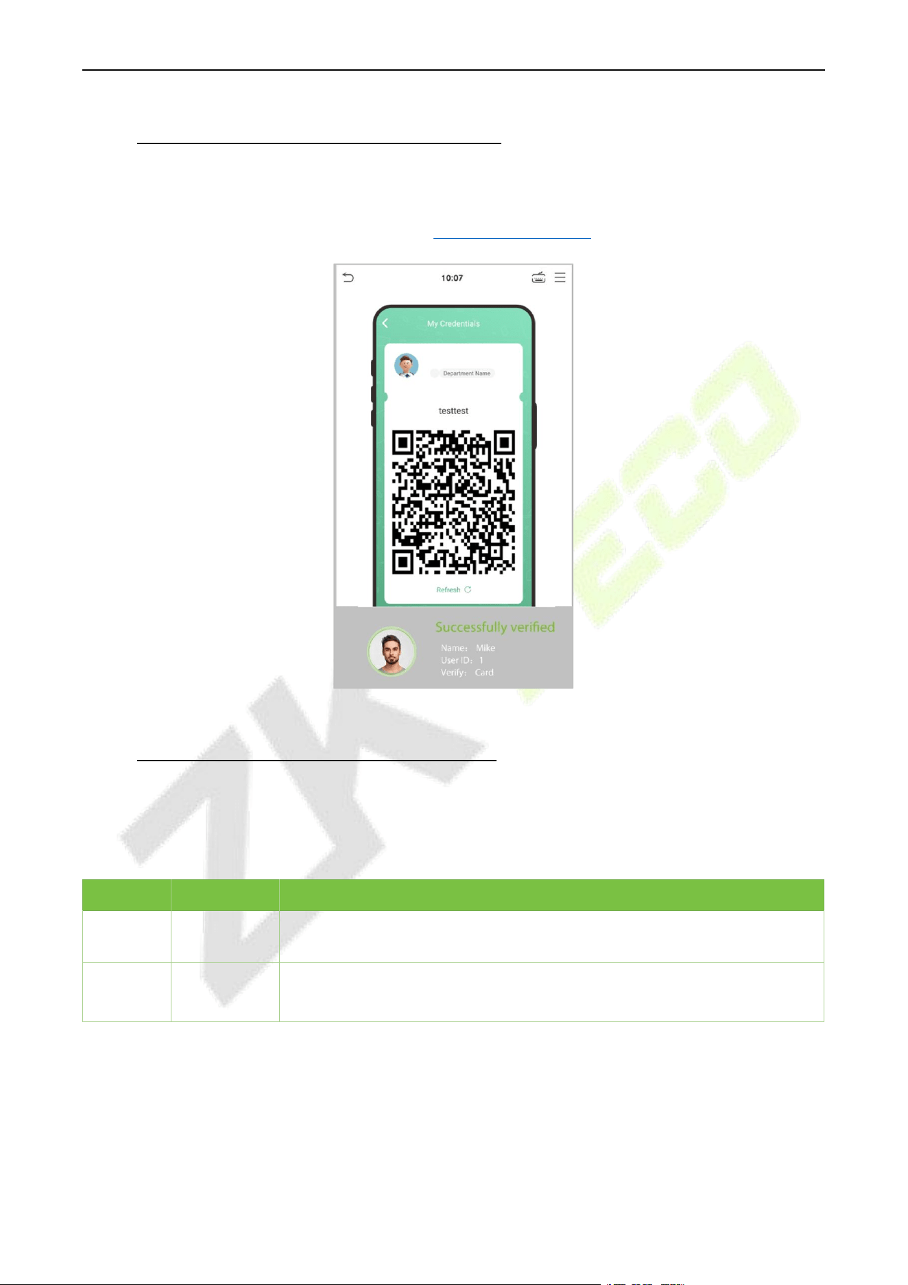
The device compares the entered password with the registered password and User ID.
Enter the user ID and press M/OK. If an employee registers a fingerprint and card in addition to the
password, the following screen will appear. Select Password to enter the 1:1 password verification
mode.
Below are the display screens after entering a correct password and a wrong password, respectively.
Verification is successful: Verification is failed:
F34 User Manual
P a g e | 17 Copyright © 2026 ZKTECO CO., LTD. All rights reserved.
4.3.4 QR Code Verification★ (PUSH Protocol)
Tap Mobile Credential on the ZKBio Zexus Mobile Page, and a QR code will appear, which includes
employee ID and card numberinformation. The QR code can replace a physical card on a specific device to
achieve contactless authentication. Please refer to 22.4 Mobile Credential.
4.3.5 Combined Verification (PUSH Protocol)
This device allows you to use different types of verification methods to increase security. There are a
total of 15 different verification combinations that can be implemented, as listed below:
Combined Verification Symbol Definition
Symbol
Definition
Explanation
/
or
This method compares the entered verification of a person with the related
verification template previously stored to that Personnel ID in the Device.
+
and
This method compares the entered verification of a person with all the
verification templates previously stored to that Personnel ID in the Device.

F34 User Manual
P a g e | 18 Copyright © 2026 ZKTECO CO., LTD. All rights reserved.
Combined Verification Mode set up procedure:
Combined verification requires personnel to register all the different verification methods.
Otherwise, employees will not be able to successfully verify the combined verification process.
For example, if an employee has only registered for password data but the Device verification
mode is set to "Password + Card", the employee will not be able to successfully complete the
verification procedure.
Reason:
This is because the Device compares the password template of the person with the registered
verification template (both the Card and the Password) previously stored to that Personnel ID in
the Device.
But, since the employee has only registered their password and not their card, the verification
process will not be successful, and the device will display the "Verification Failed."
F34 User Manual
P a g e | 19 Copyright © 2026 ZKTECO CO., LTD. All rights reserved.
5 Main Menu
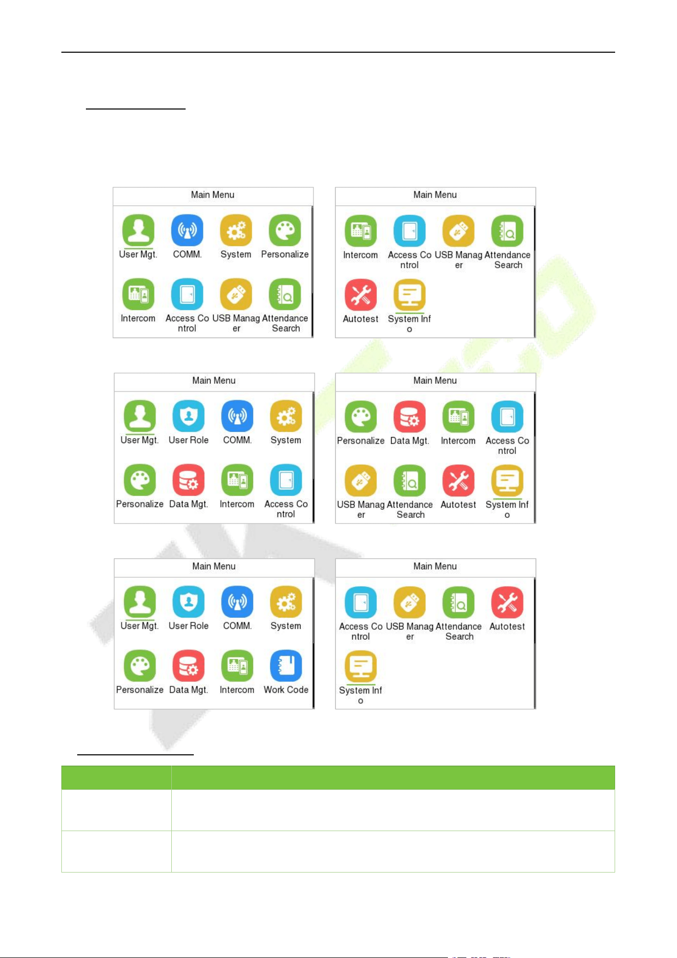
Press M/OK on the initial interface to enter the main menu, as shown below:
Note: The menu display may vary depending on the device type (BEST Protocol/A&C PUSH/T&A PUSH).
BEST Protocol
A&C PUSH
T&A PUSH
Function Description
Menu
Description
User Mgt.
To Add, Edit, View, and Delete information of a User. (Only support viewing user
information when the device type is BEST Protocol.)
User Role
To set the permission scope of the custom role and enroller for the users, for
example the system's operating rights. (Only for PUSH Protocol)

F34 User Manual
P a g e | 20 Copyright © 2026 ZKTECO CO., LTD. All rights reserved.
COMM.
To set the relevant parameters of Network, Serial Comm, PC Connection, Cellular
Data Network
★,
Wi-Fi
★
, Cloud Server, Wiegand and Network Diagnosis.
System
To set parameters related to the system, including Date Time, Attendance/Access
Logs Settings, Fingerprint, Device Type Settings, USB Upgrade, Security Settings,
Update Firmware Online and resetting to factory settings.
Personalize
To customize settings of User Interface, Voice, Bell Schedules, Punch State Options
(Only for T&A PUSH) and Shortcut Key Mappings settings (Only for T&A PUSH).
Data Mgt.
To delete the data. (Only for PUSH Protocol)
Access Control
To set the parameters of the lock and the relevant access control device including
options like Time schedule/Time rule settings, Holiday Settings, Access groups,
Combine verification, Anti-Passback Setup, and Duress Option Settings.
USB Manager
To upload or download the specific data by a USB drive.
Attendance
Search
To query the specified event logs.
Work Code
Set different type of work. (Only for T&A PUSH)
Autotest
To automatically test whether each module functions properly, including the LCD
Screen, Audio, Keyboard, fingerprint sensor and Real-Time Clock.
System Info
To view Privacy Policy, Data Capacity and Device and Firmware information of the
current device.
F34 User Manual
P a g e | 21 Copyright © 2026 ZKTECO CO., LTD. All rights reserved.
6 User Management
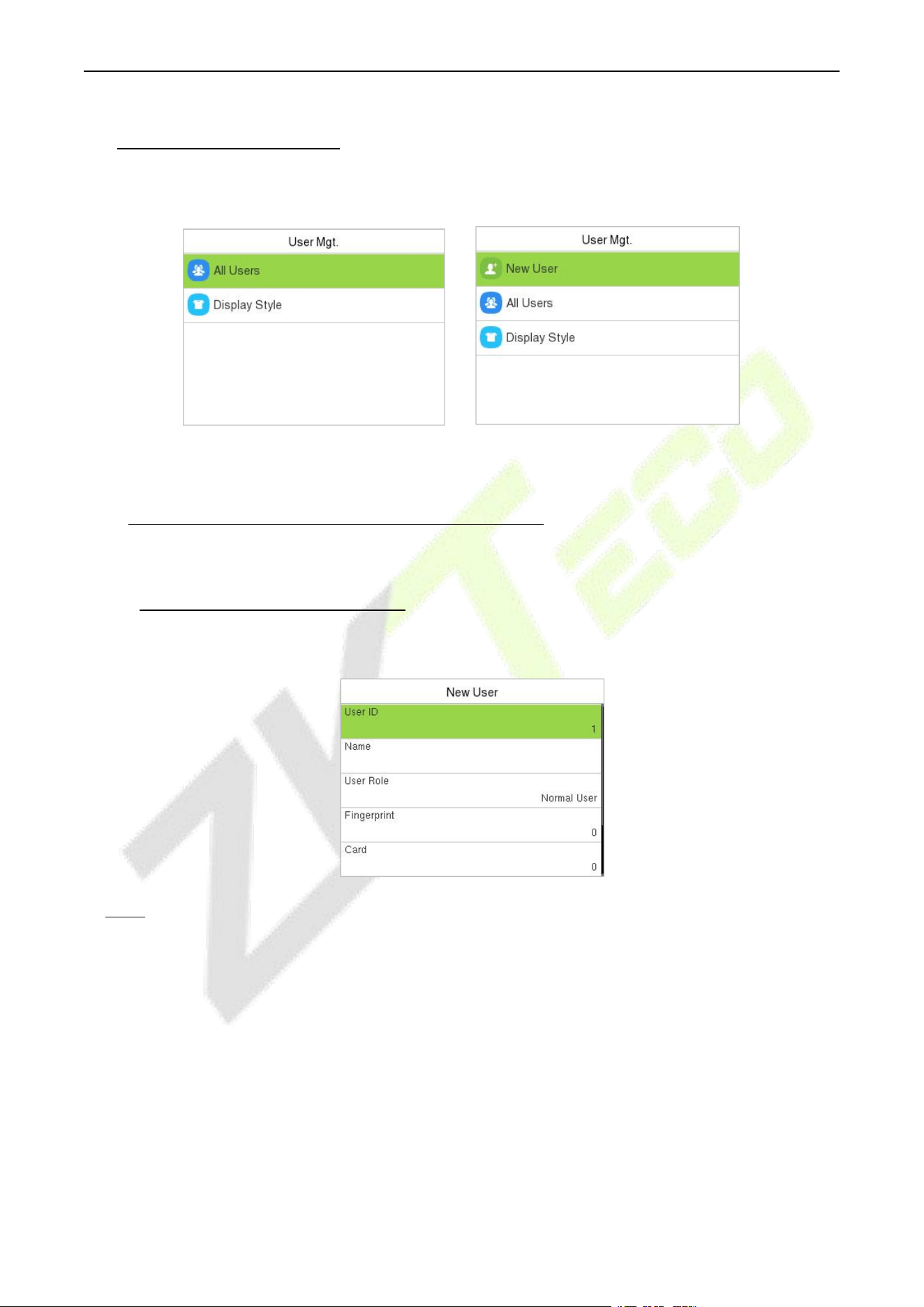
When the device is on the initial interface, press [M/OK] button and enter User Mgt..
BEST Protocol PUSH Protocol
6.1 New User Registration (PUSH Protocol)
Select New User on the User Mgt. interface to add a new user.
6.1.1 Register a User ID and Name
Enter the User ID and Name.
Note:
1. A name can be taken up to 36 characters long.
2. The user ID may contain 1 to 14 digits by default, supporting both numbers and alphabetic
characters.
3. During the initial registration, you can modify your ID, but not after registration.
4. If the message "Duplicated!" appears, you must choose a different User ID because the one you
entered already exists.
F34 User Manual
P a g e | 22 Copyright © 2026 ZKTECO CO., LTD. All rights reserved.
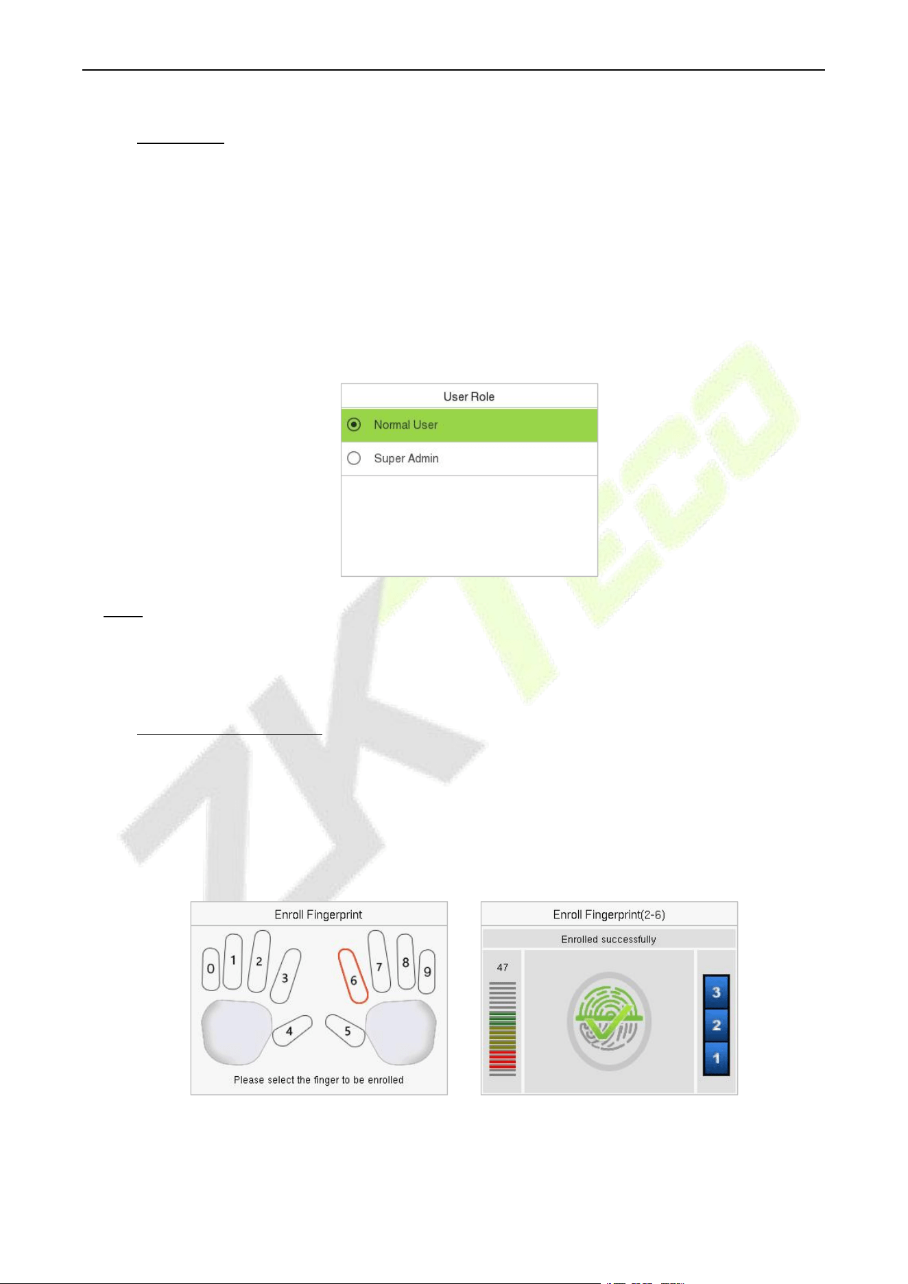
6.1.2 User Role
On the New User interface, select User Role to set the user’s role as either Normal User or Super
Admin.
Super Admin: The Super Administrator owns all management privileges in the Device.
Normal User: If the Super Admin is registered already in the device, then the Normal Users will
not have the privilege to manage the system and can only access authentic verifications.
User Defined Roles: The Normal User can also be assigned custom roles with User Defined Role.
The user can be permitted to access several menu options as required.
Note: If the selected user role is the Super Admin, then the user must pass the identity authentication
to access the main menu. The authentication is based on the authentication method(s) that the super
administrator has registered.
6.1.3 Register Fingerprint
Select Fingerprint in the New User interface to enter the fingerprint registration page.
Select the finger to be enrolled.
Press the same finger on the fingerprint reader three times.
Green indicates that the fingerprint was enrolled successfully.
F34 User Manual
P a g e | 23 Copyright © 2026 ZKTECO CO., LTD. All rights reserved.
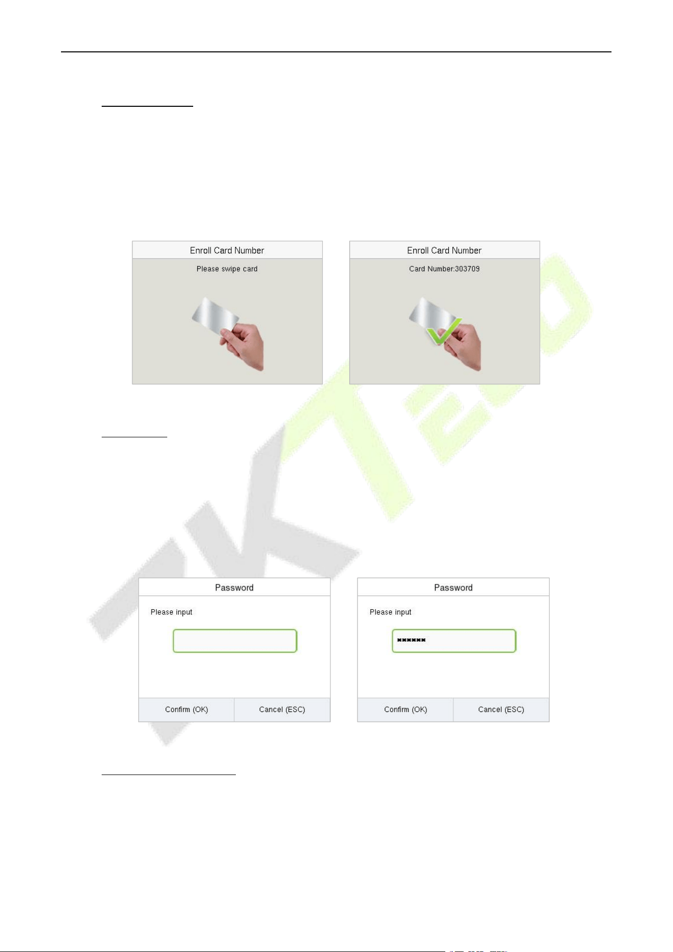
6.1.4 Card Number
Select Card Number in the New User interface to enter the card registration page.
On the card interface, swipe the card under the card reading area. The registration of the card will be
successful.
If the card has already been registered, the message "Error! Card already enrolled" appears. The
registration interface appears as follows:
6.1.5 Password
Select Password in the New User interface to enter the password registration page.
On the Password interface, enter the required password and re-enter to confirm it and press M/OK.
If the re-entered password is different from the initially entered password, then the device prompts
the message as "Password not match!", where the user needs to re-confirm the password again.
The password may contain 6 to 8 digits by default.
6.1.6 Access Control Role
The Access Control Role sets the door access privilege for each user. It includes the access group, time
period and duress fingerprint.
Enter Access Control Role > Access Group to assign the registered users to different groups for
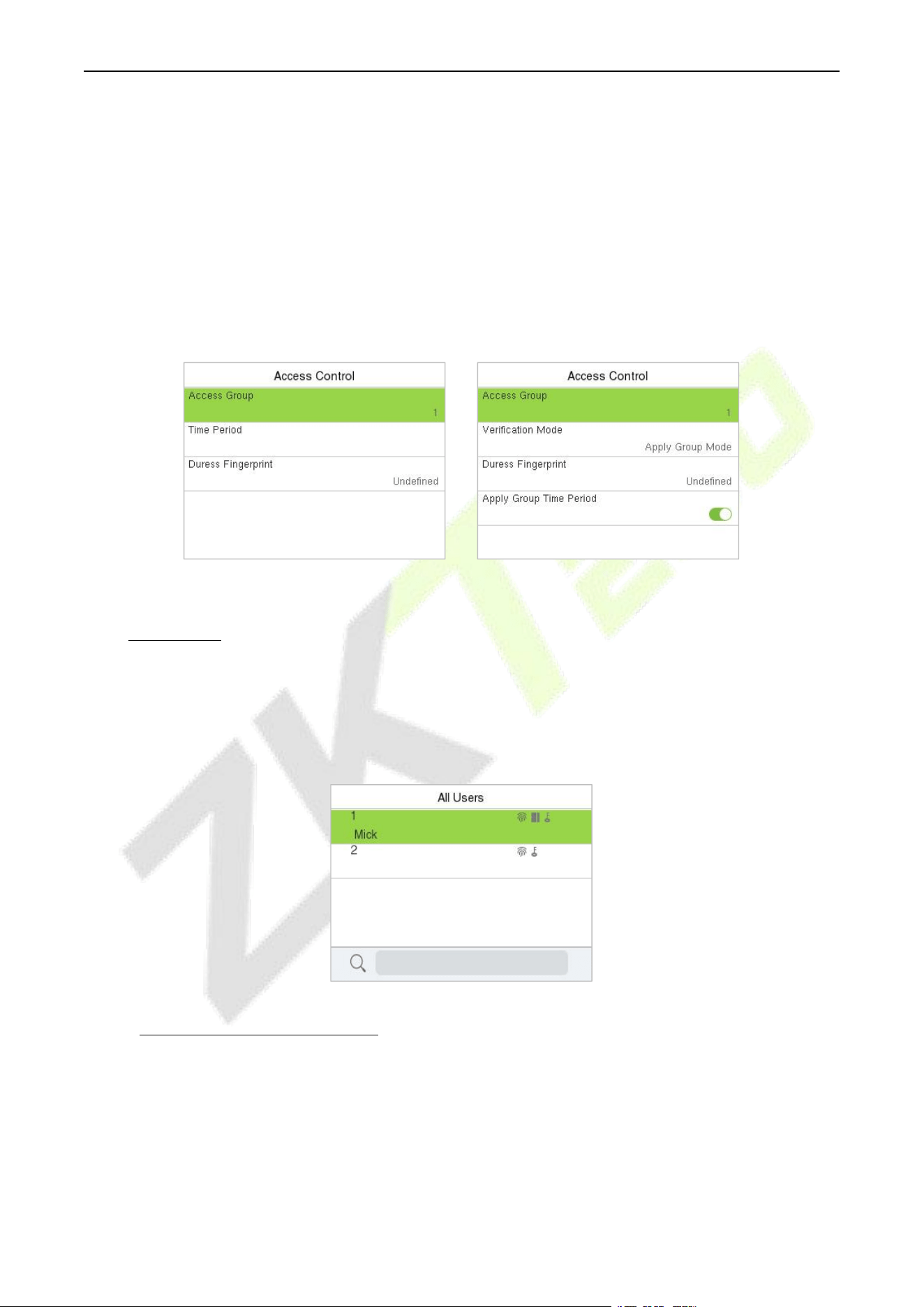
F34 User Manual
P a g e | 24 Copyright © 2026 ZKTECO CO., LTD. All rights reserved.
better management. New users belong to Group 1 by default and can be reassigned to other
groups. The device supports up to 99 Access Control groups.
Select Time Period, to select the time to use.
The user may specify one or more fingerprints that have been registered as a duress fingerprint(s).
When press the finger corresponding to the duress fingerprint on the sensor and pass the
verification, the system will immediately generate an external alarm.
Enter Verification Mode to select verification mode for the user.
Select whether to apply the group time period for this user.
A&C PUSH T&A PUSH
6.2 All Users
When the device is on the initial interface, press [M/OK] button and enter User Mgt. > All Users.
On the All Users interface, enter the required retrieval keyword (where the keyword may be the user
ID or full name) on the search bar on the user’s list and the system will search for the related user
information.
6.2.1 Edit User (PUSH Protocol)
On the All-Users interface, select the required user from the list and select Edit to edit the user
information.
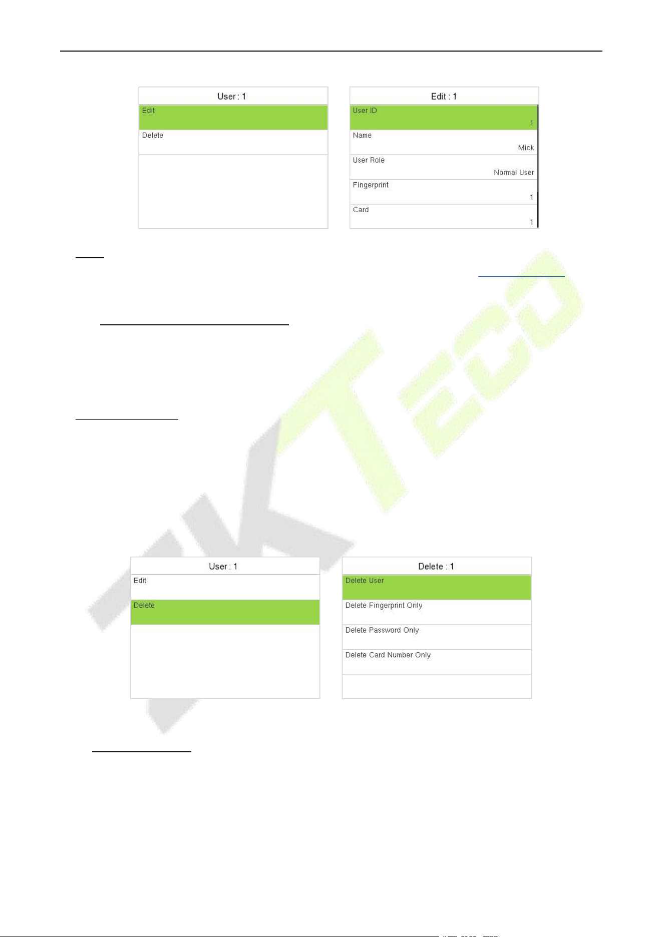
F34 User Manual
P a g e | 25 Copyright © 2026 ZKTECO CO., LTD. All rights reserved.
Note: The process of editing the user information is the same as adding a new user, except that the
User ID cannot be modified while editing a user. The process in detail refers to "User Registration".
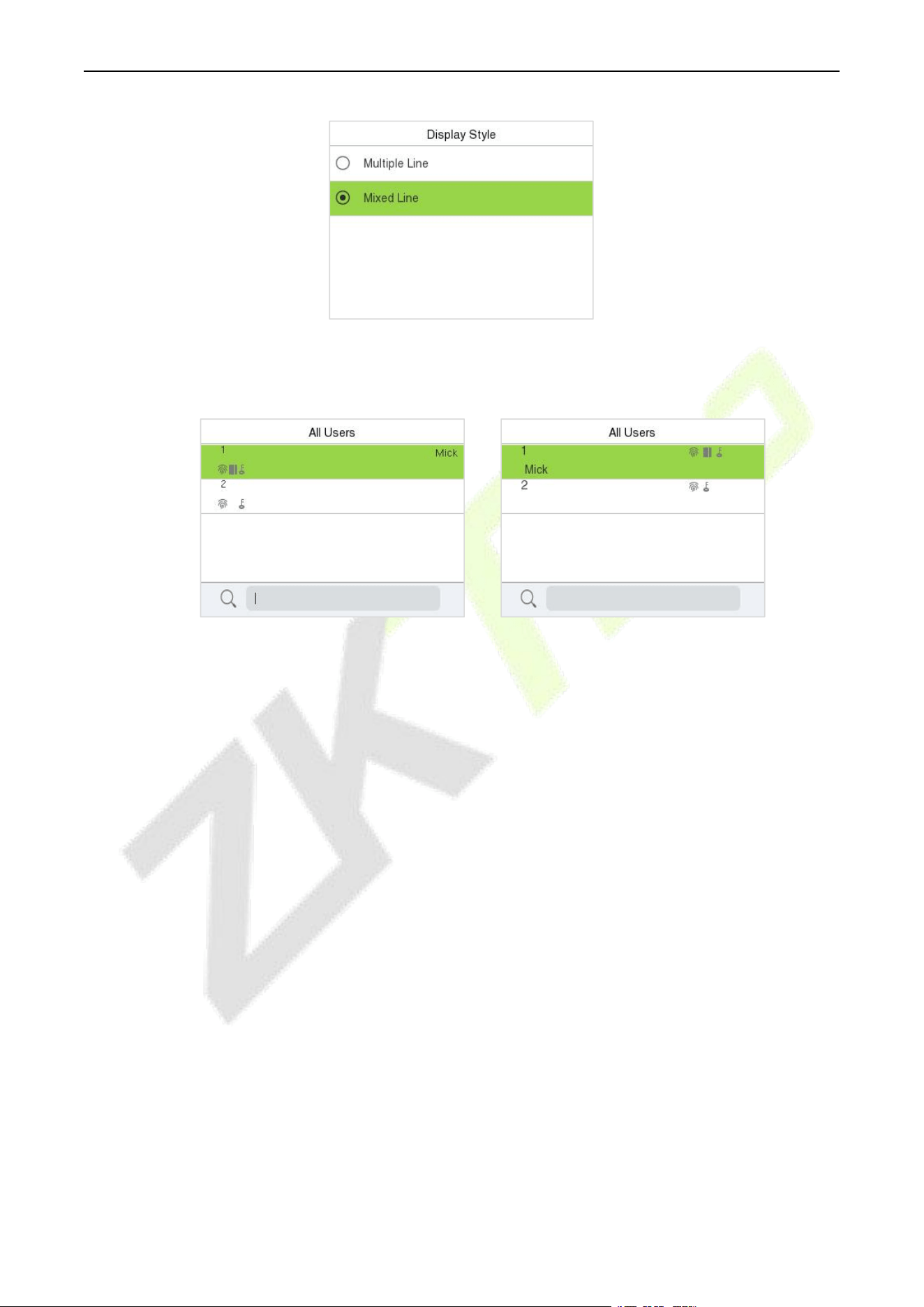
6.2.2 Delete User (PUSH Protocol)
On the All Users interface, select the required user from the list and select Delete to delete the user or
specific user information from the device. On the Delete interface, select the required operation, and
then press M/OK to confirm the deletion.
Delete Operations:
Delete User: Deletes all the user information (deletes the selected User as a whole) from the Device.
Delete User Role Only: Deletes the user's administrator privileges and make the user a normal user.
Delete Fingerprint Only: Deletes the fingerprint information of the selected user.
Delete Password Only: Deletes the password information of the selected user.
Delete Card Number Only: Deletes the card information of the selected user.
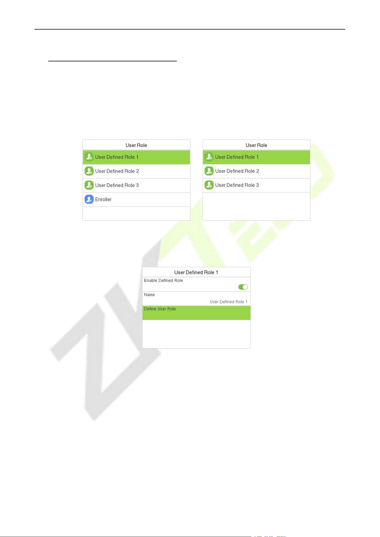
6.3 Display Style
When the device is on the initial interface, press [M/OK] button and enter User Mgt. > Display Style.
F34 User Manual
P a g e | 26 Copyright © 2026 ZKTECO CO., LTD. All rights reserved.
All the Display Styles are shown as below:
Multiple Line: Mixed Line:
F34 User Manual
P a g e | 27 Copyright © 2026 ZKTECO CO., LTD. All rights reserved.
7 User Role (PUSH Protocol)
User Role allows you to assign specific permissions to certain users based on their requirements.
When the device is on the initial interface, press [M/OK] button and enter User Role > User Defined
Role to set the user defined permissions.
The permission scope of the custom role can be set up into 3 roles, that is, the custom operating
scope of the menu functions of the user.
A&C PUSH T&A PUSH
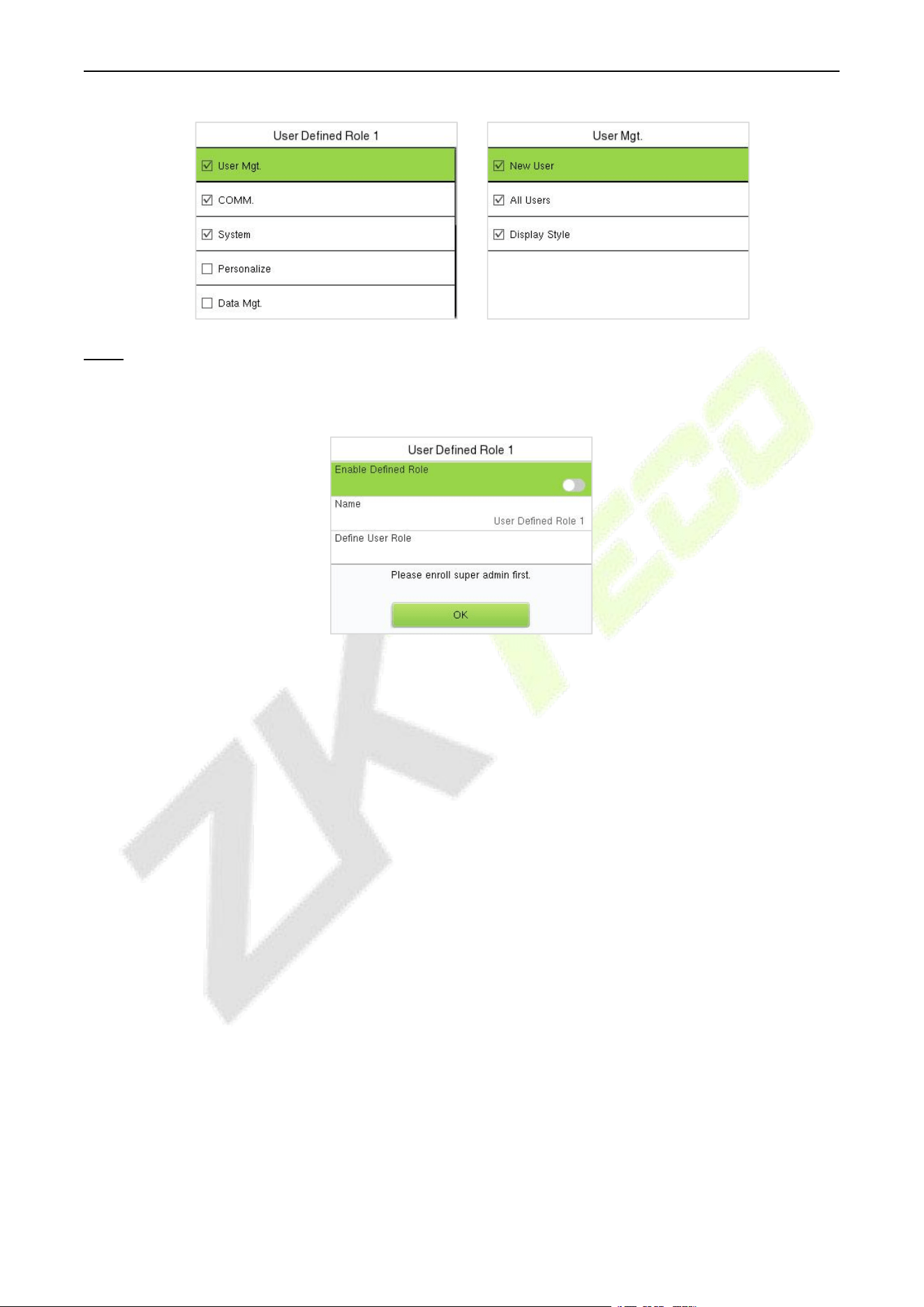
On the User Defined Role interface, toggle Enable Defined Role to enable or disable the user
defined role.
Then, by selecting on Define User Role, select the required privileges for the new role, and then
press the M/OK key.
When assigning privileges, the main menu function names will be displayed on the left and its sub-
menus will be listed on the right.
First select the required Main Menu function name, then press M/OK and select its required sub-
menus from the list.
F34 User Manual
P a g e | 28 Copyright © 2026 ZKTECO CO., LTD. All rights reserved.
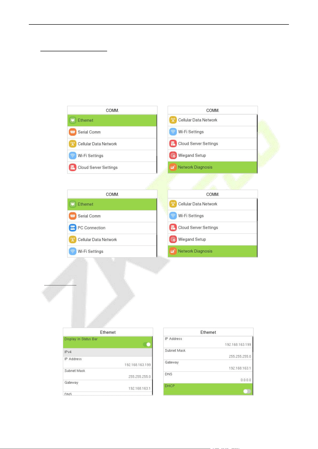
Note: If the User Role is enabled for the Device, enter User Mgt. > New User > User Role to assign the
created roles to the required users. But if there is no super administrator registered in the Device, then the
device will prompt "Please enroll super admin first." when enabling the User Role function.
F34 User Manual
P a g e | 29 Copyright © 2026 ZKTECO CO., LTD. All rights reserved.
8 Communication
Communication Settings are used to set the parameters of the Network, Serial Comm, PC Connection,
Cellular Data Network★, Wi-Fi★, Cloud Server, Wiegand, and Network Diagnosis.
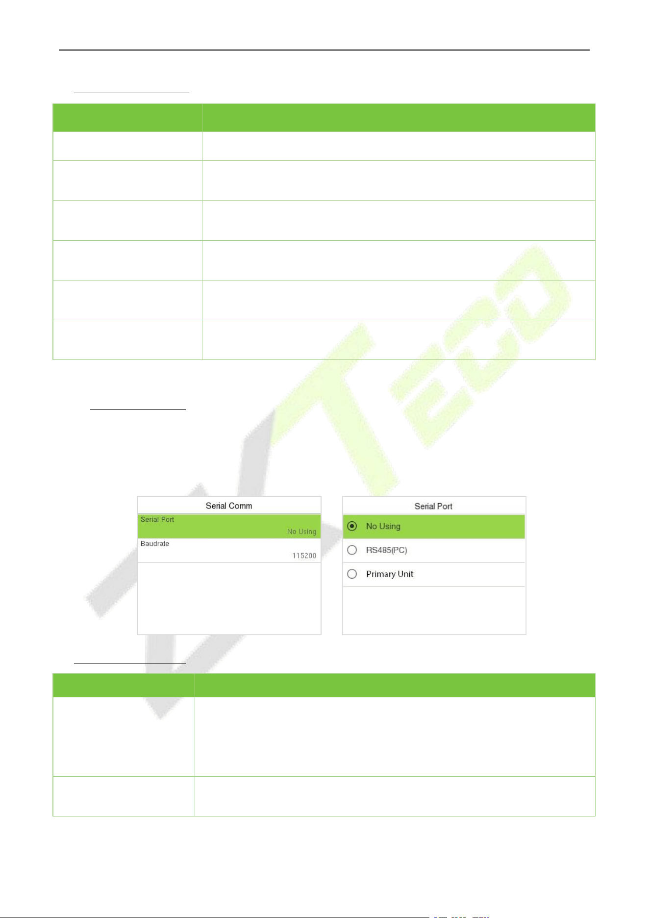
When the device is on the initial interface, press [M/OK] button and enter COMM.
BEST Protocol
PUSH Protocol
8.1 Ethernet
When the device needs to communicate with a PC via the Ethernet, you need to configure network
settings and make sure that the device and the PC connecting to the same network segment.
Select Ethernet on the COMM. Settings interface to configure the settings.
F34 User Manual
P a g e | 30 Copyright © 2026 ZKTECO CO., LTD. All rights reserved.
Function Description:
Function Name
Description
Display in Status Bar
Toggle to set whether to display the network icon on the status bar.
IP Address
The default IP address is 192.168.1.201. It can be modified according to the
network availability.
Subnet Mask
The default Subnet Mask is 255.255.255.0. It can be modified according to
the network availability.
Gateway
The Default Gateway address is 0.0.0.0. It can be modified according to the
network availability.
DNS
The default DNS address is 0.0.0.0. It can be modified according to the
network availability.
DHCP
Dynamic Host Configuration Protocol dynamically allocates IP addresses for
clients via server.
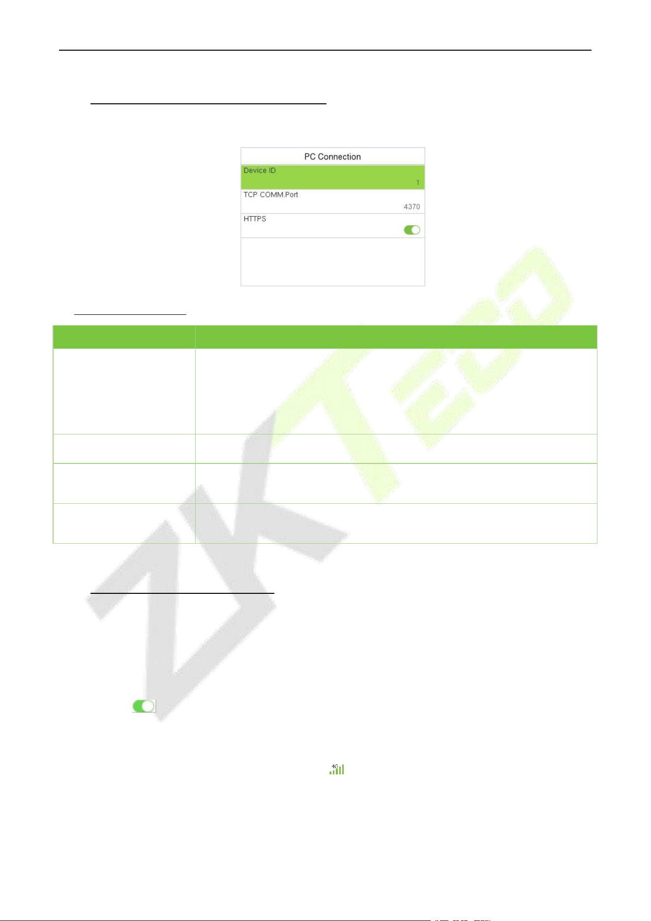
8.2 Serial Comm
Serial Comm function establishes communication with the device through a serial port (Primary Unit
function).
Select Serial Comm on the COMM. Settings interface.
Function Description
Function Name
Description
Serial Port
No Using: No communication with the device through the serial port.
RS485(PC): Communicates with the device through RS485 serial port.
Primary Unit: When RS485 is used as the function of "Primary Unit", it can be
connected to a reader.
Baudrate
When the serial port is set as Primary Unit, the baudrate is 115200 by default
and cannot be modified.
F34 User Manual
P a g e | 31 Copyright © 2026 ZKTECO CO., LTD. All rights reserved.
8.3 PC Connection (PUSH Protocol)
Select PC Connection on the COMM. Settings interface to configure the communication settings.
Function Description
Function Name
Description
Comm Key
This menu only appears after enabling Standalone Communication function
in System> Security Settings.
To improve the security of data, the Comm Key needs to be entered before
the device can be connected to the C/S software. It can be changed as
needed.
Device ID
It is the identification number of the device, which ranges between 1 and 254.
TCP COMM.Port
The default TCP COMM Port value is 4370. It can be modified according to the
network availability.
HTTPS
Based on HTTP, transmission encryption and identity authentication ensure
the security of the transmission process.
8.4 Cellular Data Network★
When the equipment is in the Dial-Up Network, make sure the device is in the coverage of GPRS or
WCDMA signal, and it is must know of the used modem type, APN name and access number and so on.
Before enabling, please insert the All-in-one card into the 4G module first.
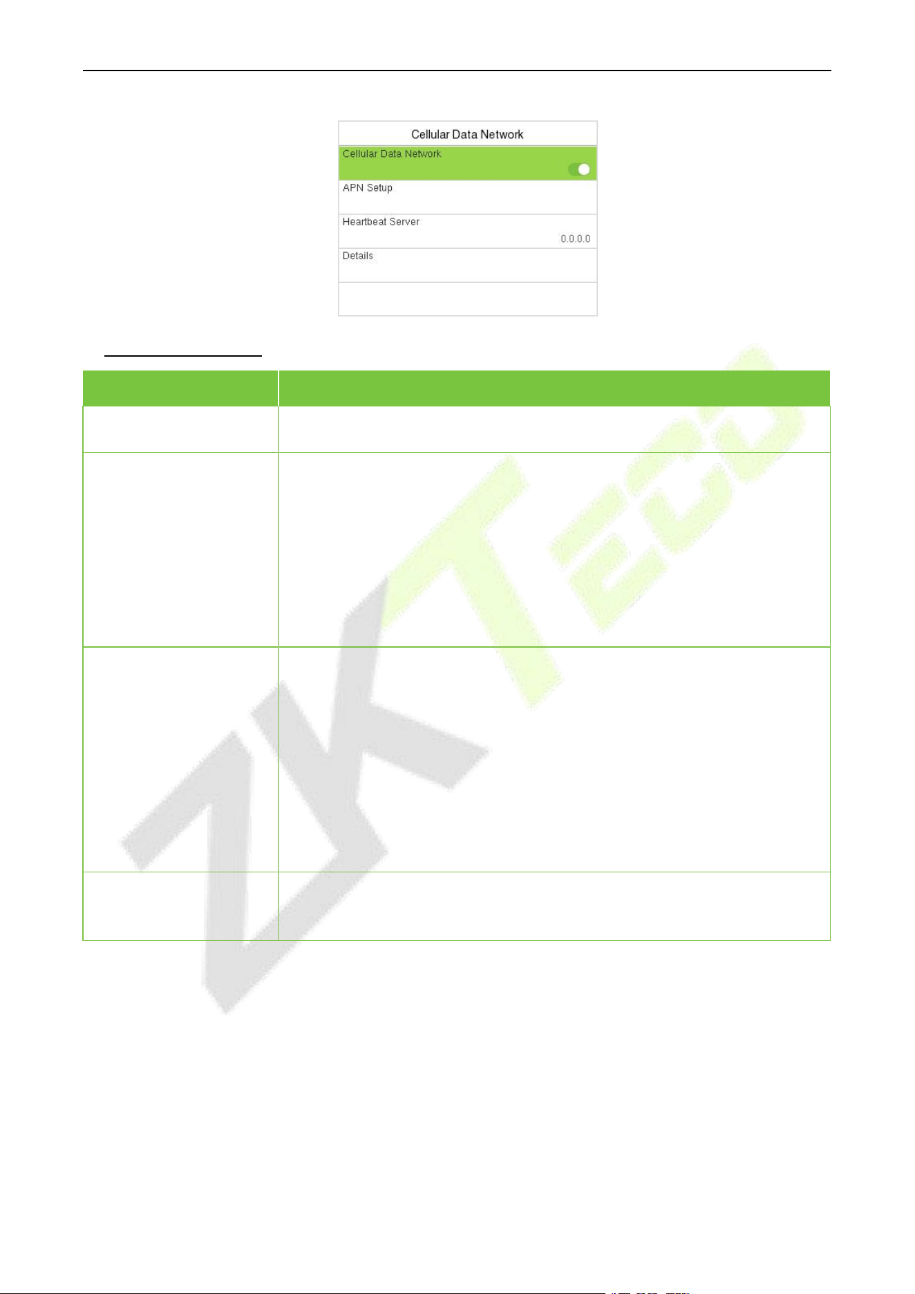
Select Cellular Data Network on the Comm. Settings interface.
Toggle the button to enable the Cellular Data Network. Under normal circumstances, the device
will automatically connect to the mobile network after being enabled. If you cannot connect, you can
manually set the relevant parameters to connect. When the mobile network is connected successfully,
the initial interface will display the mobile network logo.
F34 User Manual
P a g e | 32 Copyright © 2026 ZKTECO CO., LTD. All rights reserved.
Function Description
Function Name
Description
Cellular Data Network
Whether to enable the mobile network.
APN Setup
To set APN information, such as the dialed number, user name and password.
APN: Access Point Name, provided by the operator and not supported in
the CDMA network.
Dial Number: Number of the cellular data network.
User Name and Password: To verify whether the user has the privilege to
use this network.
Heartbeat Server
To detect the connection status of the mobile network. The terminal
periodically sends ICMP packets to the heartbeat server to detect whether
the terminal is online. When the terminal is offline, the device automatically
performs dial-up connection again. Therefore, when setting the heartbeat
server, ensure that the heartbeat server can be pinged and remain online
stably for a long term.
Note: Generally, the customer can set the heartbeat server address as the
ADMS server address.
Details
To view the information about mobile network connection, such as network
mode, IP address, received data, and sent data.
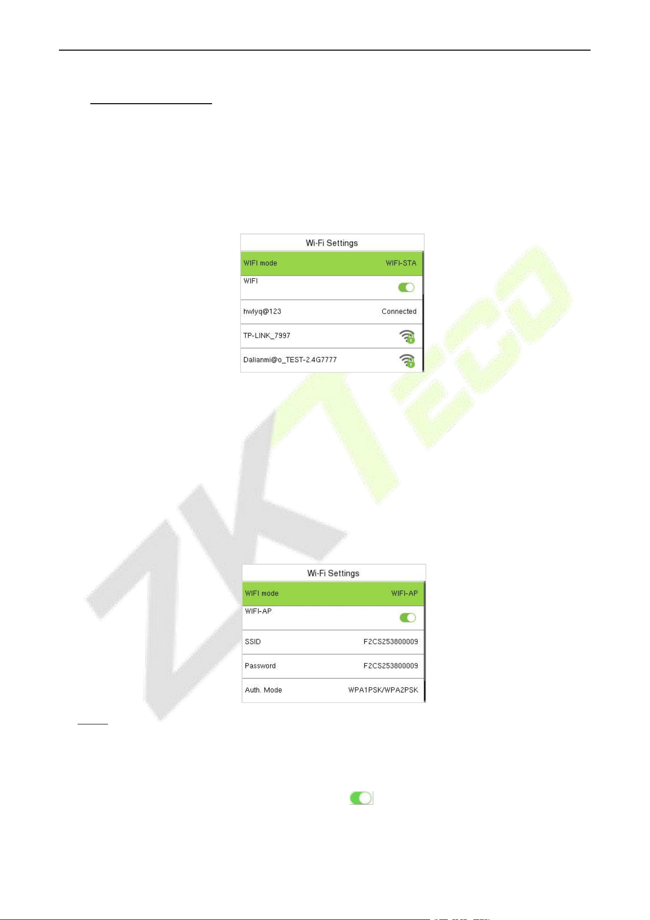
Note: To use the cellular data network function, the device must be connected to an external power
supply. Additionally, while connected to an external power supply, you must manually enable the
cellular data network function.
F34 User Manual
P a g e | 33 Copyright © 2026 ZKTECO CO., LTD. All rights reserved.
8.5 Wi-Fi Settings★
The device provides a Wi-Fi module, which can be built-in within the device module.
The Wi-Fi module enables data transmission via Wi-Fi (Wireless Fidelity) and establishes a wireless
network environment. Wi-Fi is enabled by default in the device. If you don't need to use the Wi-Fi
network, you can toggle the Wi-Fi to disable the button.
Select Wi-Fi Settings on the COMM. Settings interface to configure the Wi-Fi settings.
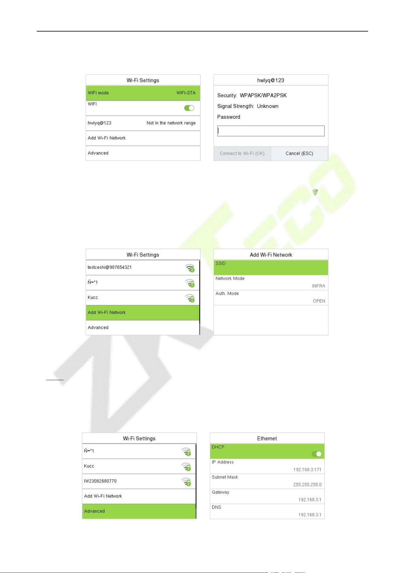
WiFi mode
It is WIFI-STA by default. The WIFI-AP mode is suitable for use in scenarios where there is no network
coverage or when quick configuration of the access control system is required. For example, it can be
used for simple testing after installation.
In WIFI-AP mode, the device can emit an AP hotspot, allowing users to connect to the WiFi hotspot via
mobile devices (smartphones, tablets, etc.) and then access the device's built-in webserver directly
through a browser for remote management.
When connecting to the AP hotspot for the first time, the default SSID and password are: [Device
Serial Number] / [Device Serial Number].
Note: For security considerations, the device's AP hotspot will automatically turn off every 30
minutes to prevent unauthorized access.
Searching the Wi-Fi Network
Wi-Fi is enabled in the device by default. Toggle the button to enable or disable Wi-Fi.
Once the Wi-Fi is turned on, the device will search for the available Wi-Fi within the network range.
F34 User Manual
P a g e | 34 Copyright © 2026 ZKTECO CO., LTD. All rights reserved.
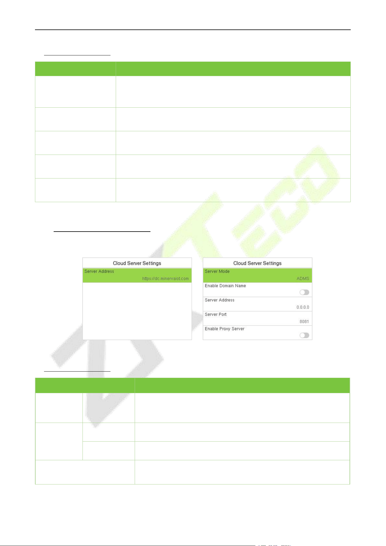
Select the required Wi-Fi name from the available list and input the correct password in the
password interface, and then press M/OK.
When the Wi-Fi is connected successfully, the initial interface will display the Wi-Fi logo.
Adding Wi-Fi Network Manually
The Wi-Fi can also be added manually if the required Wi-Fi does not show on the list.
Note: After successfully adding the Wi-Fi manually, follow the same process to search for the added Wi-
Fi name.
Advanced Setting
On the Wi-Fi Settings interface, select Advanced to set the relevant parameters as required.
WIFI Enabled: Select the required
network from the searched network list.
Select the password field to enter the
password and press M/OK.
Select Add Wi-Fi Network to add the
Wi-Fi manually.
On this interface, enter the Wi-Fi network
parameters. (The added network must
exist.)
F34 User Manual
P a g e | 35 Copyright © 2026 ZKTECO CO., LTD. All rights reserved.
Function Description
Function Name
Description
DHCP
Dynamic Host Configuration Protocol (DHCP) dynamically allocates IP
addresses to network clients. If the DHCP is enabled, then the IP cannot be
set manually.
IP Address
The IP address for the Wi-Fi network, the default is 0.0.0.0. It can be modified
according to the network availability.
Subnet Mask
The default Subnet Mask of the Wi-Fi network is 255.255.255.0. It can be
modified according to the network availability.
Gateway
The Default Gateway address is 0.0.0.0. It can be modified according to the
network availability.
DNS
The default DNS is 0.0.0.0. It can be modified according to the network
availability.
8.6 Cloud Server Settings
Select Cloud Server Settings on the COMM. Settings interface to connect with the ADMS server.
BEST Protocol PUSH Protocol
Function Description
Function Name
Description
Enable
Domain
Name
Server
Address
Once this mode is turned ON, the domain name mode "http://... " will
be used, such as http://www.XYZ.com, while "XYZ" denotes the
domain name.
Disable
Domain
Name
Server
Address
The IP address of the ADMS server.
Server Port
Port used by the ADMS server.
Enable Proxy Server
The IP address and the port number of the proxy server is set
manually when the proxy is enabled.
F34 User Manual
P a g e | 36 Copyright © 2026 ZKTECO CO., LTD. All rights reserved.
8.7 Wiegand Setup
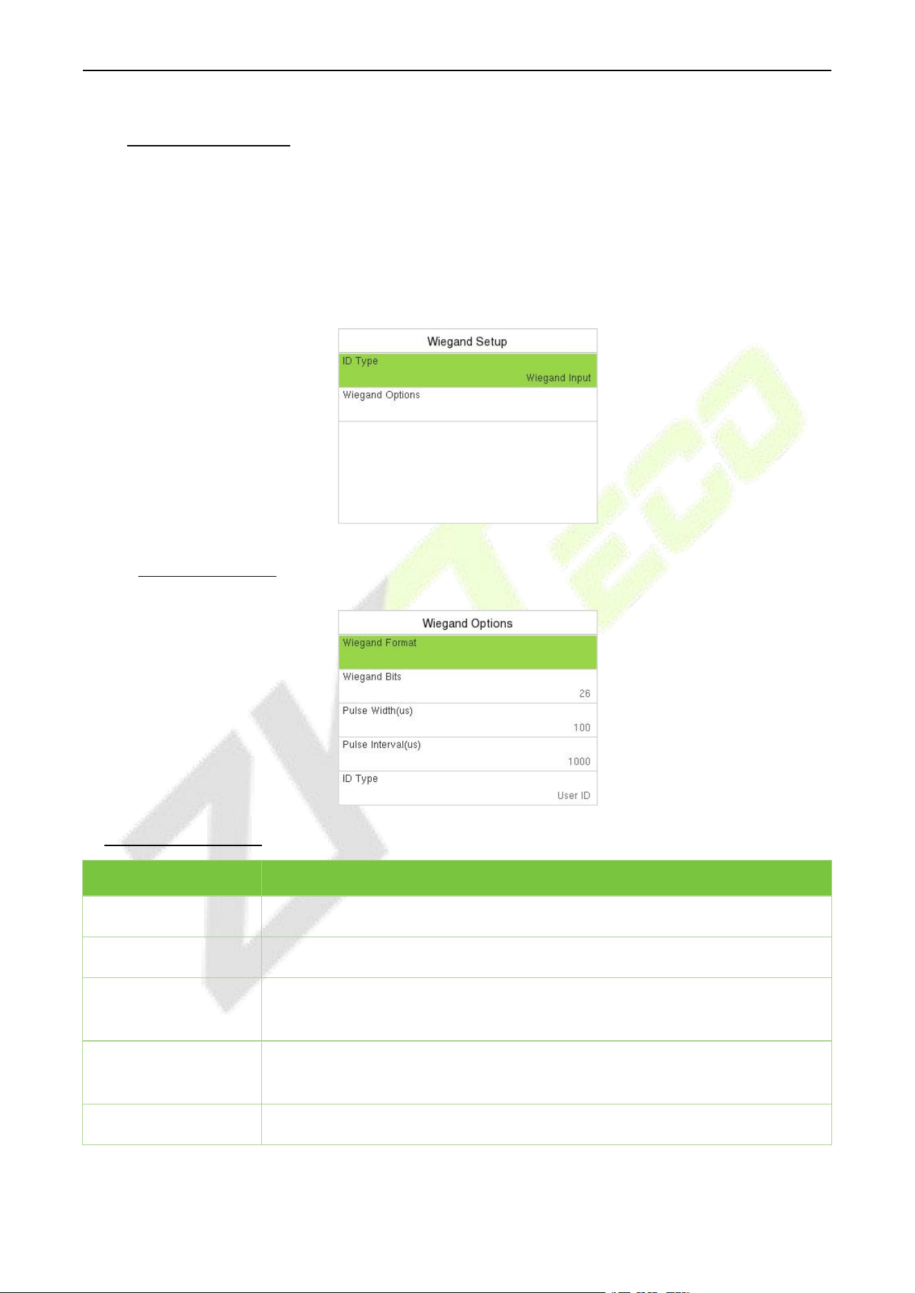
It is used to set the Wiegand input and output parameters.
Select Wiegand Setup on the COMM. Settings interface to set up the Wiegand input and output
parameters.
Note: The Wiegand interface is shared, and the user can choose to use either the Wiegand input or
Wiegand output function to interface with different Wiegand devices.
8.7.1 Wiegand Input
Function Description
Function Name
Description
Wiegand Format
Its value can be 26 bits, 32 bits, 34 bits, 36 bits, 37 bits, 50 bits and 64 bits.
Wiegand Bits
The number of bits of the Wiegand data.
Pulse Width(us)
The value of the pulse width sent by Wiegand is 100 microseconds by default,
which can be adjusted within the range of 20 to 400 microseconds.
Pulse Interval(us)
The default value is 1000 microseconds and can be adjusted within the range
of 200 to 20000 microseconds.
ID Type
Select between the User ID and card number.

F34 User Manual
P a g e | 37 Copyright © 2026 ZKTECO CO., LTD. All rights reserved.
Various Common Wiegand Format Description:
Wiegand Format
Description
Wiegand26
ECCCCCCCCCCCCCCCCCCCCCCCCO
It consists of 26 bits of binary code. The 1
st
bit is the even parity bit of the 2
nd
to
13
th
bits, while the 26
th
bit is the odd parity bit of the 14
th
to 25
th
bits. The 2
nd
to
25
th
bits is the card numbers.
Wiegand26a
ESSSSSSSSCCCCCCCCCCCCCCCCO
It consists of 26 bits of binary code. The 1
st
bit is the even parity bit of the 2
nd
to
13
th
bits, while the 26
th
bit is the odd parity bit of the 14
th
to 25
th
bits. The 2
nd
to
9
th
bits is the site codes, while the 10
th
to 25
th
bits are the card numbers.
Wiegand34
ECCCCCCCCCCCCCCCCCCCCCCCCCCCCCCCCO
It consists of 34 bits of binary code. The 1
st
bit is the even parity bit of the 2
nd
to
17
th
bits, while the 34
th
bit is the odd parity bit of the 18
th
to 33
rd
bits. The 2
nd
to
25
th
bits is the card numbers.
Wiegand34a
ESSSSSSSSCCCCCCCCCCCCCCCCCCCCCCCCO
It consists of 34 bits of binary code. The 1
st
bit is the even parity bit of the 2
nd
to
17
th
bits, while the 34
th
bit is the odd parity bit of the 18
th
to 33
rd
bits. The 2
nd
to
9
th
bits is the site codes, while the 10
th
to 25
th
bits are the card numbers.
Wiegand36
OFFFFFFFFFFFFFFFFCCCCCCCCCCCCCCCCMME
It consists of 36 bits of binary code. The 1
st
bit is the odd parity bit of the 2
nd
to
18
th
bits, while the 36
th
bit is the even parity bit of the 19
th
to 35
th
bits. The 2
nd
to 17
th
bits is the device codes. The 18
th
to 33
rd
bits is the card numbers, and
the 34
th
to 35
th
bits are the manufacturer codes.
Wiegand36a
EFFFFFFFFFFFFFFFFFFCCCCCCCCCCCCCCCCO
It consists of 36 bits of binary code. The 1
st
bit is the even parity bit of the 2
nd
to
18
th
bits, while the 36
th
bit is the odd parity bit of the 19
th
to 35
th
bits. The 2
nd
to
19
th
bits is the device codes, and the 20
th
to 35
th
bits are the card numbers.
Wiegand37
OMMMMSSSSSSSSSSSSCCCCCCCCCCCCCCCCCCCE
It consists of 37 bits of binary code. The 1
st
bit is the odd parity bit of the 2
nd
to
18
th
bits, while the 37
th
bit is the even parity bit of the 19
th
to 36
th
bits. The 2
nd
to 4
th
bits is the manufacturer codes. The 5
th
to 16
th
bits is the site codes, and
the 21
st
to 36
th
bits are the card numbers.
Wiegand37a
EMMMFFFFFFFFFFSSSSSSCCCCCCCCCCCCCCCCO
It consists of 37 bits of binary code. The 1
st
bit is the even parity bit of the 2
nd
to
18
th
bits, while the 37
th
bit is the odd parity bit of the 19
th
to 36
th
bits. The 2
nd
to
4
th
bits is the manufacturer codes. The 5
th
to 14
th
bits is the device codes,
and15
th
to 20
th
bits are the site codes, and the 21
st
to 36
th
bits are the card
numbers.
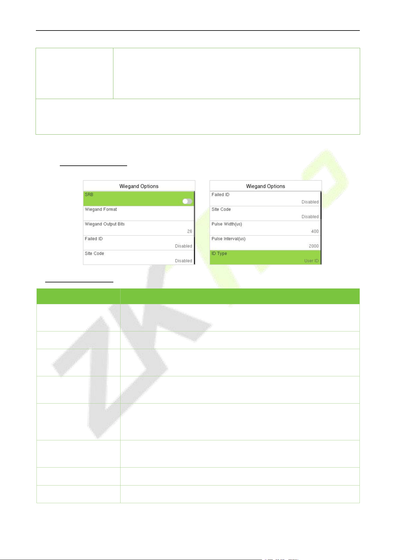
F34 User Manual
P a g e | 38 Copyright © 2026 ZKTECO CO., LTD. All rights reserved.
Wiegand50
ESSSSSSSSSSSSSSSSCCCCCCCCCCCCCCCCCCCCCCCCCCCCCCCCO
It consists of 50 bits of binary code. The 1
st
bit is the even parity bit of the 2
nd
to
25
th
bits, while the 50
th
bit is the odd parity bit of the 26
th
to 49
th
bits. The 2
nd
to
17
th
bits is the site codes, and the 18
th
to 49
th
bits are the card numbers.
"C" denotes the card number; "E" denotes the even parity bit; "O" denotes the odd parity bit.
"F" denotes the facility code; "M" denotes the manufacturer code; "P" denotes the parity bit; and "S"
denotes the site code.
8.7.2 Wiegand Output
Function Description
Function Name
Description
SRB
When SRB is enabled, the lock is controlled by the SRB to prevent the lock
from being opened due to device removal.
Wiegand Format
Its value can be 26 bits, 32 bits, 34 bits, 36 bits, 37 bits, 50 bits and 64 bits.
Wiegand Output Bits
After selecting the required Wiegand format, select the corresponding
output bit digits from the Wiegand format.
Failed ID
If the verification fails, the system will send the failed ID to the device and
replace the card number or personnel ID with the new one.
Site Code
It is similar to the device ID. The difference is that a site code can be set
manually and is repeatable on a different device. The valid value ranges
from 0 to 256 by default.
Pulse Width(us)
The time width represents the changes in the quantity of electric charge
with regular high-frequency capacitance within a specified time.
Pulse Interval(us)
The time interval between pulses.
ID Type
Select the ID types as either User ID or card number.
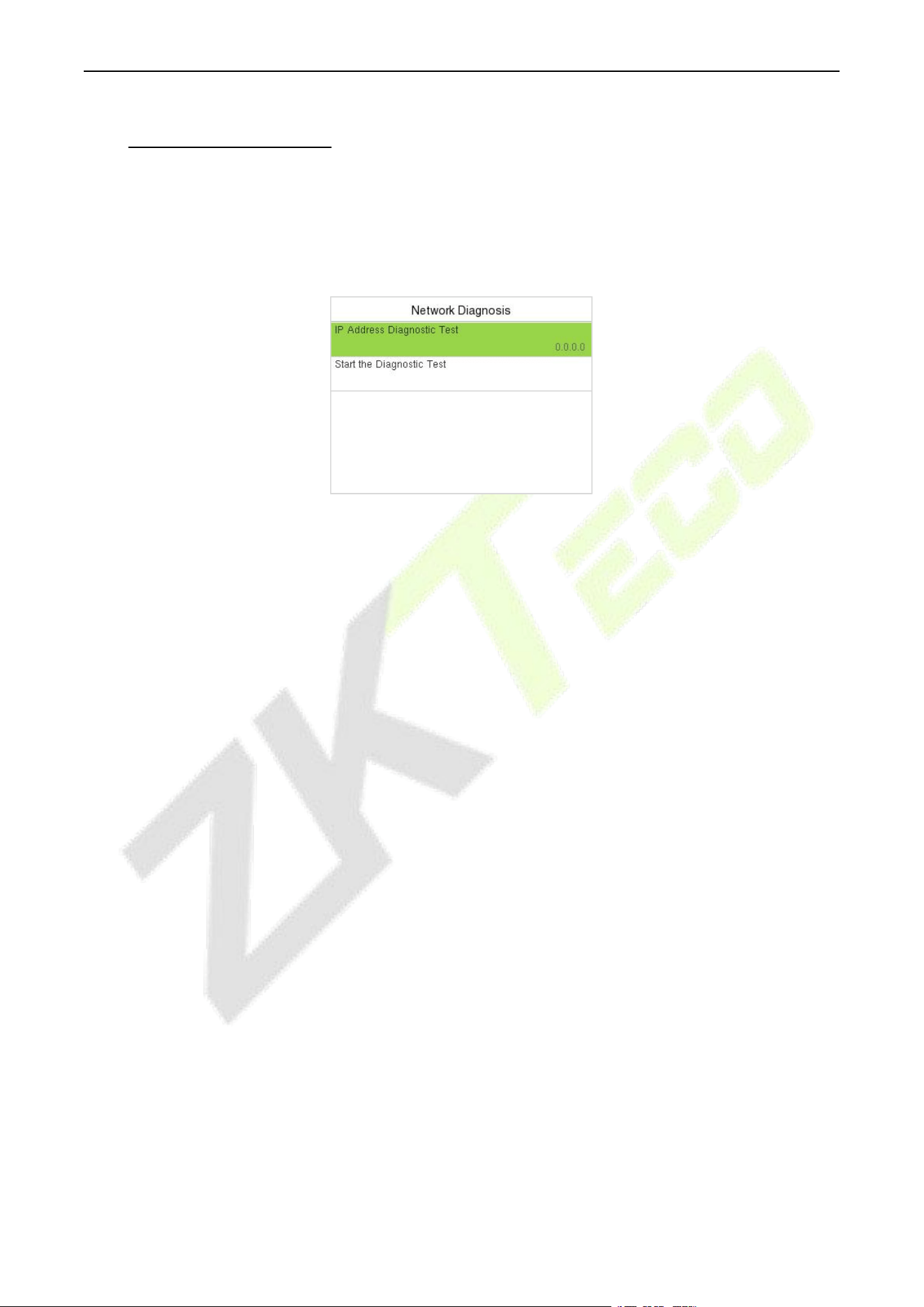
F34 User Manual
P a g e | 39 Copyright © 2026 ZKTECO CO., LTD. All rights reserved.
8.8 Network Diagnosis
It helps to set the network diagnosis parameters.
Select Network Diagnosis on the COMM. Settings interface. Enter the IP address that needs to be
diagnosed and select Start the Diagnostic Test to check whether the network can connect to the
device.
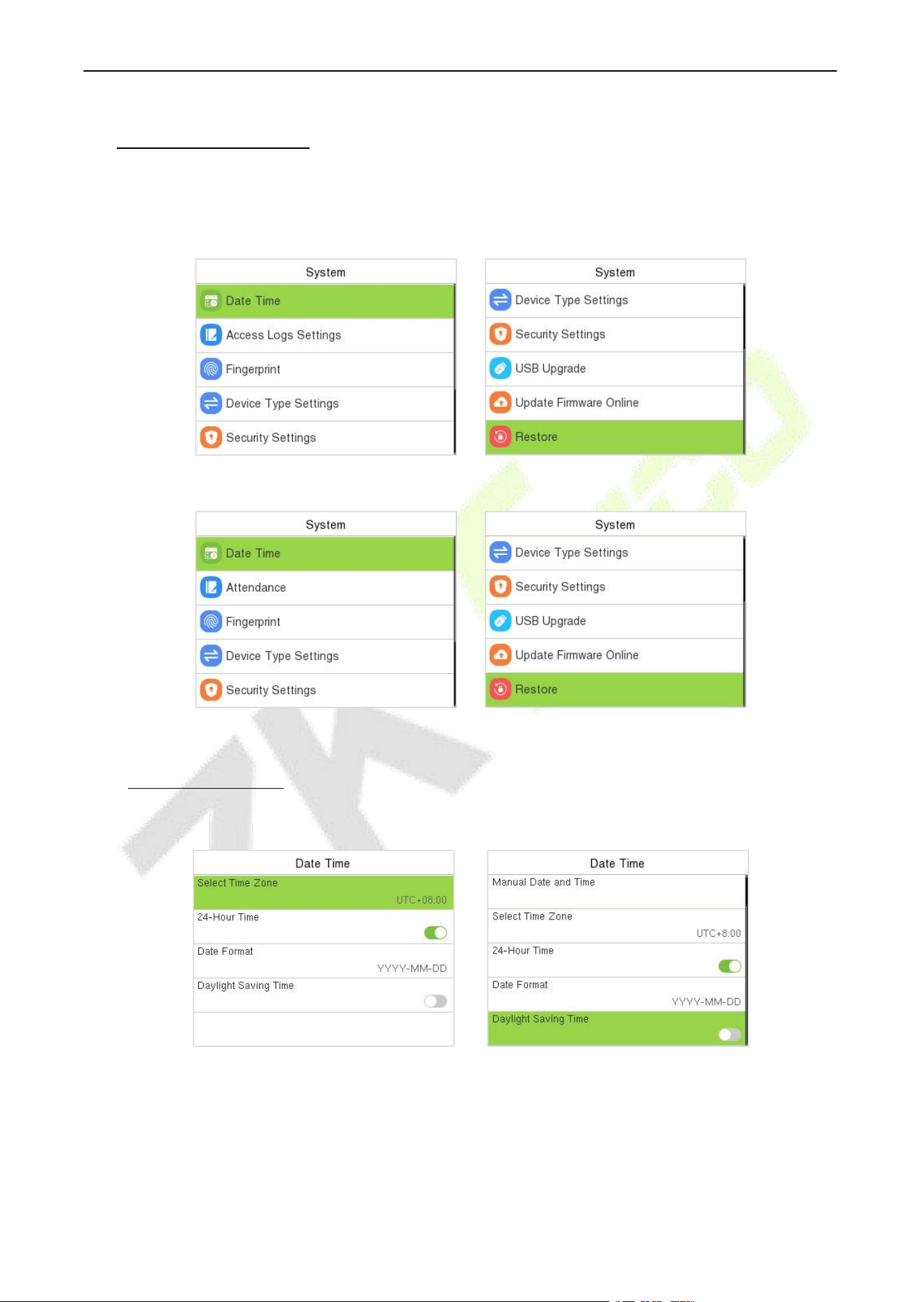
F34 User Manual
P a g e | 40 Copyright © 2026 ZKTECO CO., LTD. All rights reserved.
9 System Settings
It helps to set related system parameters to optimize the accessibility of the device.
When the device is on the initial interface, press [M/OK] button and enter System.
BEST Protocol/A&C PUSH
T&A PUSH
9.1 Date and Time
Select Date Time on the System interface to set the date and time.
BEST Protocol PUSH Protocol
Select NTP Server to enable automatic time synchronization based on the service address you
enter.
Select Manual Date and Time to manually set the date and time and then press M/OK and save.
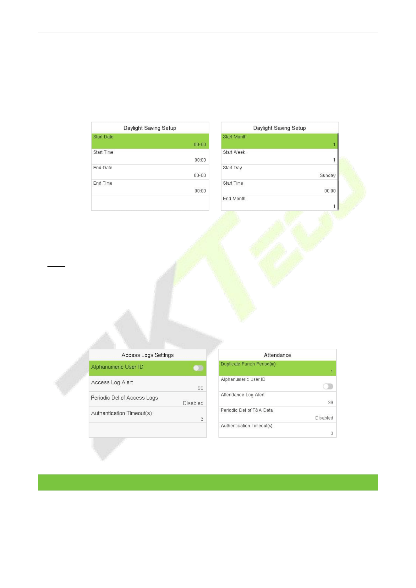
F34 User Manual
P a g e | 41 Copyright © 2026 ZKTECO CO., LTD. All rights reserved.
Select Time Zone to manually select the time zone where the device is located.
Enable or disable the 24-Hour Time. Select the Date Format to set the date format.
Select Daylight Saving Time to enable or disable the function. If enabled, enter Daylight Saving
Mode to select a daylight-saving mode and then enter Daylight Saving Setup to set the switch
time.
Week Mode Date Mode
When restoring the factory settings, the time (24-hour) and date format (YYYY-MM-DD) can be
restored, but the device date and time cannot be restored.
Note: For example, if a user sets the time of the device from 18:35 on March 15, 2024 to 18:30 on
January 1, 2025. After restoring the factory settings, the time of the device will remain at 18:30 on
January 1, 2025.
9.2 Access Logs Settings / Attendance
Select Access Logs Settings / Attendance on the System interface.
BEST Protocol/A&C PUSH T&A PUSH
A&C Terminal:
Function Name
Description
Alphanumeric User ID
Enable/Disable the alphanumeric as User ID.

F34 User Manual
P a g e | 42 Copyright © 2026 ZKTECO CO., LTD. All rights reserved.
Access Log Alert
When the record space of the access reaches the maximum threshold
value, the device automatically displays the memory space warning.
Users may disable the function or set a valid value between 1 and
9999.
Periodic Del of Access Logs
When access logs reach its maximum capacity, the device
automatically deletes a set of old access logs.
Users may disable the function or set a valid value between 1 and 999.
Authentication Timeout(s)
The amount of time taken to display a successful verification
message. Valid value: 1 to 9 seconds.
T&A Terminal:
Function Name
Description
Duplicate Punch Period(m)
Within a set time period (unit: minutes), the duplicated attendance
record will not be reserved (value ranges from 1 to 999999 minutes).
Alphanumeric User ID
Enable/Disable the alphanumeric as User ID.
Attendance Log Alert
When the record space of the attendance reaches the maximum
threshold value, the device automatically displays the memory space
warning.
Users may disable the function or set a valid value between 1 and
9999.
Periodic Del of T&A Data
When attendance logs reach its maximum capacity, the device
automatically deletes a set of old attendance logs.
Users may disable the function or set a valid value between 1 and 999.
Authentication Timeout(s)
The amount of time taken to display a successful verification message.
Valid value: 1 to 9 seconds.
9.3 Fingerprint
Select Fingerprint on the System interface to go to the Fingerprint parameter settings.
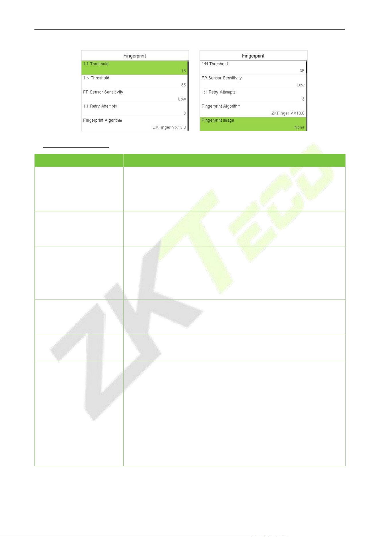
F34 User Manual
P a g e | 43 Copyright © 2026 ZKTECO CO., LTD. All rights reserved.
Function Description
Function Name
Description
1:1 Threshold
Under 1:1 verification method, the verification will only be successful
when the similarity between the acquired fingerprint data and the
fingerprint template associated with the entered user ID enrolled in the
device is greater than the set value.
1:N Threshold
Under 1:N verification method, the verification will only be successful
when the similarity between the acquired fingerprint data and the
fingerprint templates enrolled in the device is greater than the set value.
FP Sensor Sensitivity
To set the sensibility of fingerprint acquisition. It is recommended to use
the default level "Medium". When the environment is dry, resulting in
slow fingerprint detection, you can set the level to "High" to raise the
sensibility; when the environment is humid, making it hard to identify the
fingerprint, you can set the level to "Low".
1:1 Retry Attempts
In 1:1 Verification, users might forget the registered fingerprint, or press
the finger improperly. To reduce the process of re-entering user ID, retry
is allowed.
Fingerprint Algorithm
Fingerprint algorithm version. Default support ZKFinger VX13.0, can
change to ZKFinger VX10.0.
Fingerprint Image
To set whether to display the fingerprint image on the screen during
fingerprint enrollment or verification. Four choices are available:
Show for Enroll: to display the fingerprint image on the screen only
during enrollment.
Show for Match: to display the fingerprint image on the screen only
during verification.
Always Show: to display the fingerprint image on screen during
enrollment and verification.
None: not to display the fingerprint image.
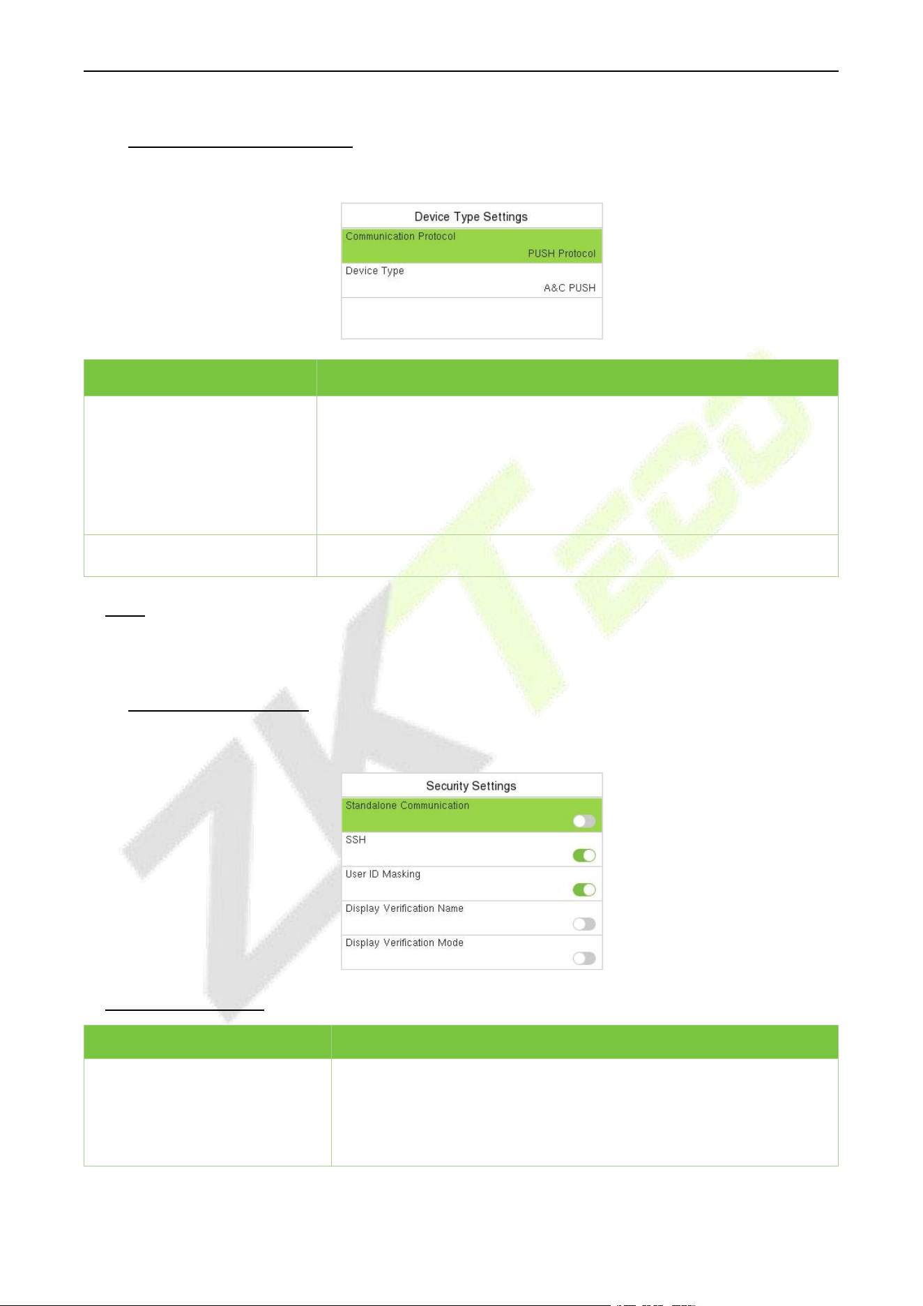
F34 User Manual
P a g e | 44 Copyright © 2026 ZKTECO CO., LTD. All rights reserved.
9.4 Device Type Settings
Select Device Type Settings on the System interface to configure the Device Type Settings.
Function Name
Description
Communication Protocol
Set the device communication protocol. It is BEST Protocol by default,
which is suitable for ZKBio Zlink.
PUSH Protocol: It can be set as A&C PUSH (which is suitable for ZKBio
CVAccess) or T&A PUSH (which is suitable for ZKBio Time Cloud/ZKBio
Time).
Device Type
Set the device as an access control terminal or attendance terminal.
Note: After changing the device type, the device will delete all the data and restart, and some functions
will be adjusted accordingly.
9.5 Security Settings
Select Security Settings on the System interface to go to the Security settings.
Function Description
Function Name
Description
Standalone Communication
By default, this function is disabled. It is used to connect the C/S
software (like ZKTime.Net, etc.). When it is switched on, a security
prompt appears, and you need to set the Comm Key, the device will
restart after you confirm.
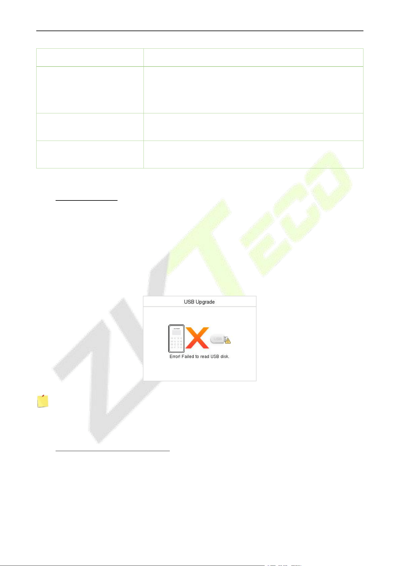
F34 User Manual
P a g e | 45 Copyright © 2026 ZKTECO CO., LTD. All rights reserved.
SSH
SSH is used to enter the background of the device for maintenance.
User ID Masking
When enabled, and then the user is successfully compared and
verified, the User ID in the displayed verification result will be
replaced with an * to achieve secure protection of sensitive private
data.
Display Verification Name
Set whether to display the username in the verification result
interface.
Display Verification Mode
Set whether to display the verification mode in the verification result
interface.
9.6 USB Upgrade
The device's firmware program can be upgraded with the upgrade file in a USB drive. Before conducting
this operation, please ensure that the USB drive contains the correct upgrade file and is properly inserted
into the device.
If no USB disk is inserted in, the system gives the following prompt after you select USB Upgrade on the
System interface.
Select USB Upgrade on the System interface.
Note: If upgrade file is needed, please contact our technical support. Firmware upgrade is not
recommenced under normal circumstances.
9.7 Update Firmware Online
Select Update Firmware Online on the System interface.
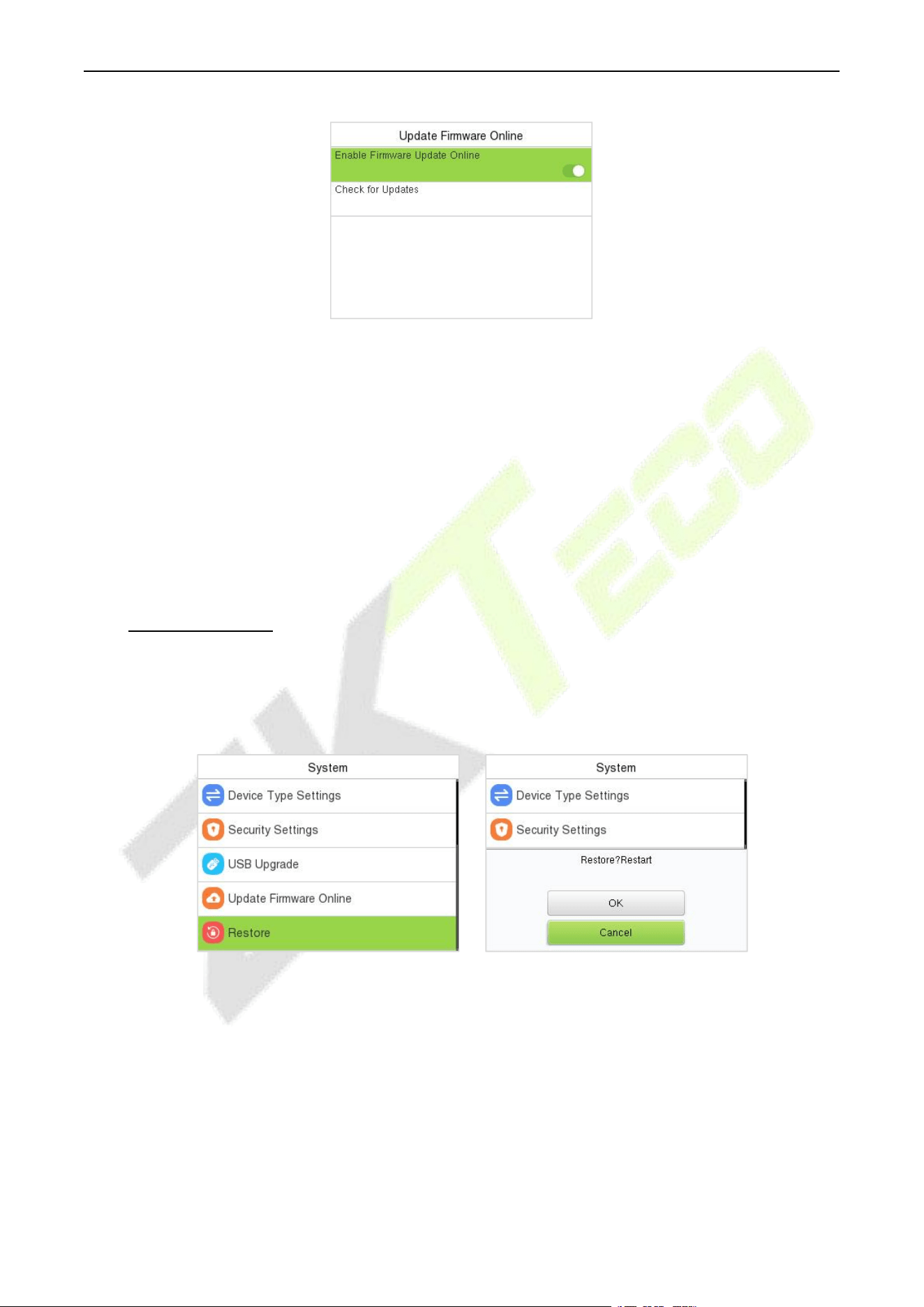
F34 User Manual
P a g e | 46 Copyright © 2026 ZKTECO CO., LTD. All rights reserved.
The Firmware Update Online function is enabled by default. Select Check for Updates it may have the
following 3 scenarios:
If the query fails, the interface will prompt "Query failed".
If the firmware version of the device is latest, it will prompt that the current firmware version
is already the latest.
If the firmware version of the device is not the latest, the version number and change log of
the latest version will be displayed. Users can choose whether to update to the latest
firmware version.
9.8 Factory Reset
The Factory Reset function restores the device settings such as communication settings and system
settings, to the default factory settings (this function does not clear registered user data).
Select Restore on the System interface and then press M/OK to restore the default factory settings.
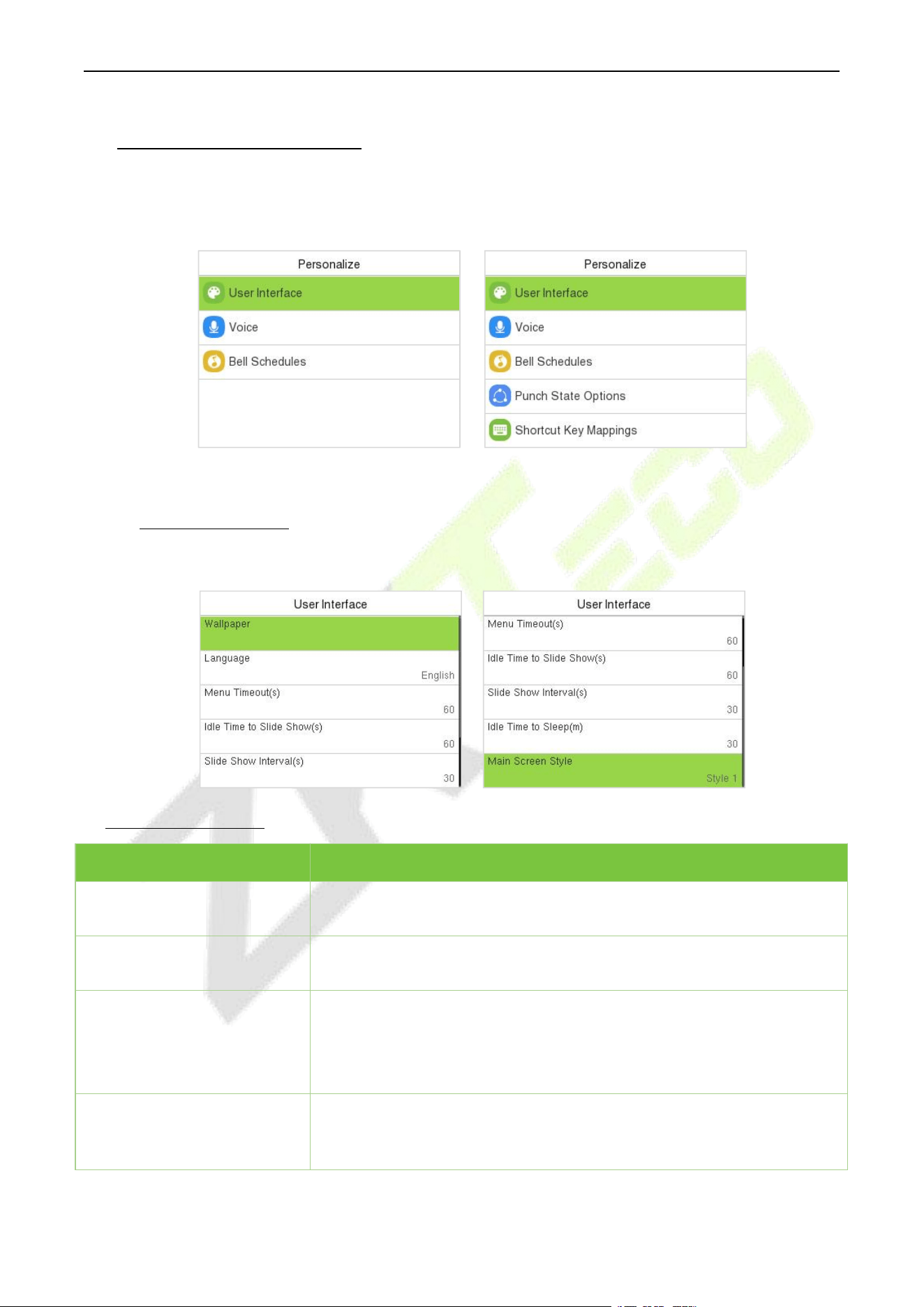
F34 User Manual
P a g e | 47 Copyright © 2026 ZKTECO CO., LTD. All rights reserved.
10 Personalize Settings
When the device is on the initial interface, press [M/OK] button and enter Personalize to customize the
interface settings, voice, bell, punch state options, and shortcut key mappings.
BEST Protocol/A&C PUSH T&A PUSH
10.1 User Interface
Select User Interface on the Personalize interface to customize the display style of the main interface.
Function Description
Function Name
Description
Wallpaper
It helps to select the main screen wallpaper according to the user
preference.
Language
It helps to select the language of the device. The device restart has taken
effect.
Menu Timeout (s)
When there is no operation, and the time exceeds the set value, the
device automatically goes back to the initial interface.
The function can either be disabled or set the required value between 60
and 99999 seconds.
Idle Time to Slide Show (s)
When there is no operation, and the time exceeds the set value, a slide
show is displayed. The function can be disabled, or you may set the value
between 3 and 999 seconds.
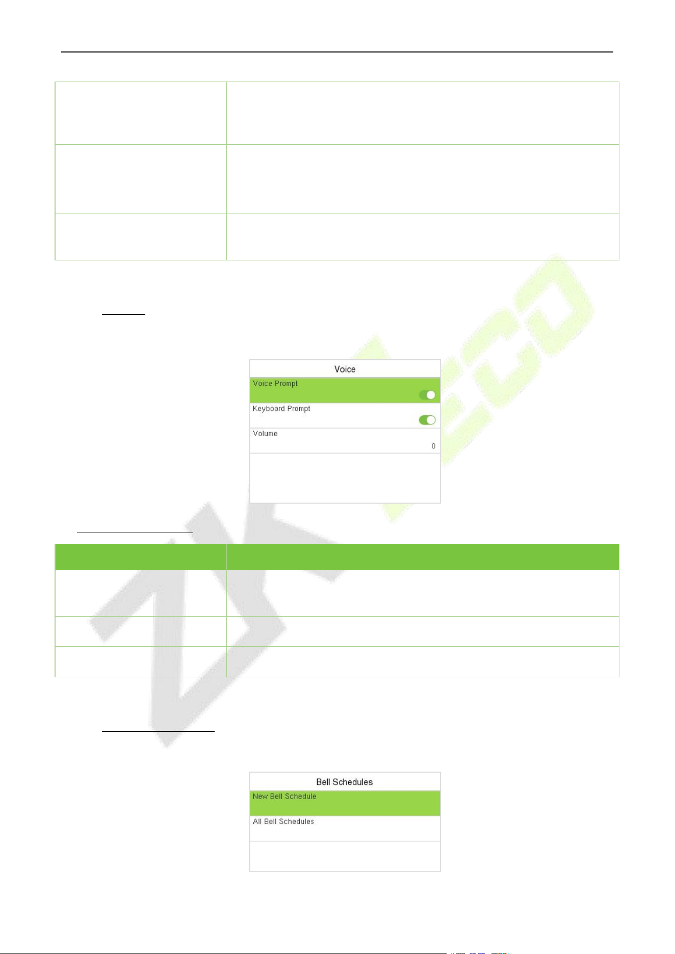
F34 User Manual
P a g e | 48 Copyright © 2026 ZKTECO CO., LTD. All rights reserved.
Slide Show Interval (s)
It is the time interval in switching between different slide show pictures.
The function can be disabled, or you may set the interval between 3 and
999 seconds.
Idle Time to Sleep (m)
If the sleep mode is activated, and when there is no operation in the
device, then the device will enter standby mode.
This function can be disabled or set a value within 1 to 999 minutes.
Main Screen Style
The style of the main screen can be selected according to the user
preference.
10.2 Voice
Select Voice on the Personalize interface to configure the voice settings.
Function Description
Function Name
Description
Voice Prompt
Toggle to enable or disable the voice prompts during function
operations.
Keyboard Prompt
Toggle to enable or disable the keypad sounds.
Volume
Adjust the volume of the device which can be set between 0 to 100.
10.3 Bell Schedules
Select Bell Schedules on the Personalize interface to configure the Bell settings.
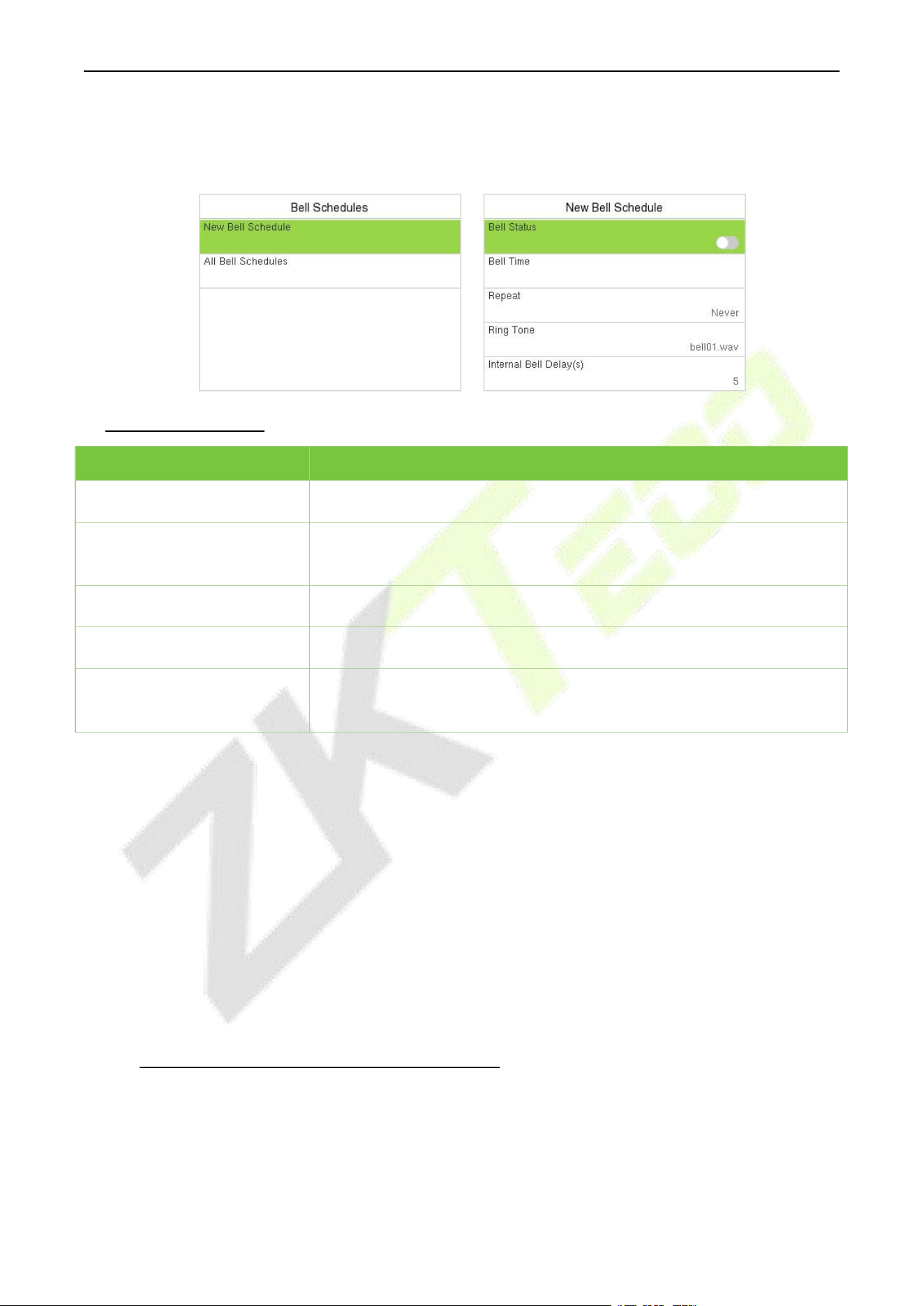
F34 User Manual
P a g e | 49 Copyright © 2026 ZKTECO CO., LTD. All rights reserved.
New Bell Schedule:
Select New Bell Schedule on the Bell Schedule interface to add a new bell schedule.
Function Description
Function Name
Description
Bell Status
Toggle to enable or disable the bell status.
Bell Time
Once the required time is set, the device automatically triggers to ring
the bell during that time.
Repeat
Set the required number of counts to repeat the scheduled bell.
Ring Tone
Select a ringtone.
Internal Bell Delay(s)
Set the replay time of the internal bell. Valid values range from 1 to 999
seconds.
All Bell Schedules:
Once the bell is scheduled, on the Bell Schedules interface, select All Bell Schedules to view the newly
scheduled bell.
Edit the Scheduled Bell:
On the All Bell Schedules interface, select the required bell schedule, and select Edit to edit the
selected bell schedule. The editing method is the same as the operations of adding a new bell schedule.
Delete a Bell Schedules:
On the All Bell Schedules interface, select the required bell schedule, select Delete, and then press
M/OK to delete the selected bell.
10.4 Punch States Options (T&A PUSH)
Select Punch States Options on the Personalize interface to configure the punch state settings.
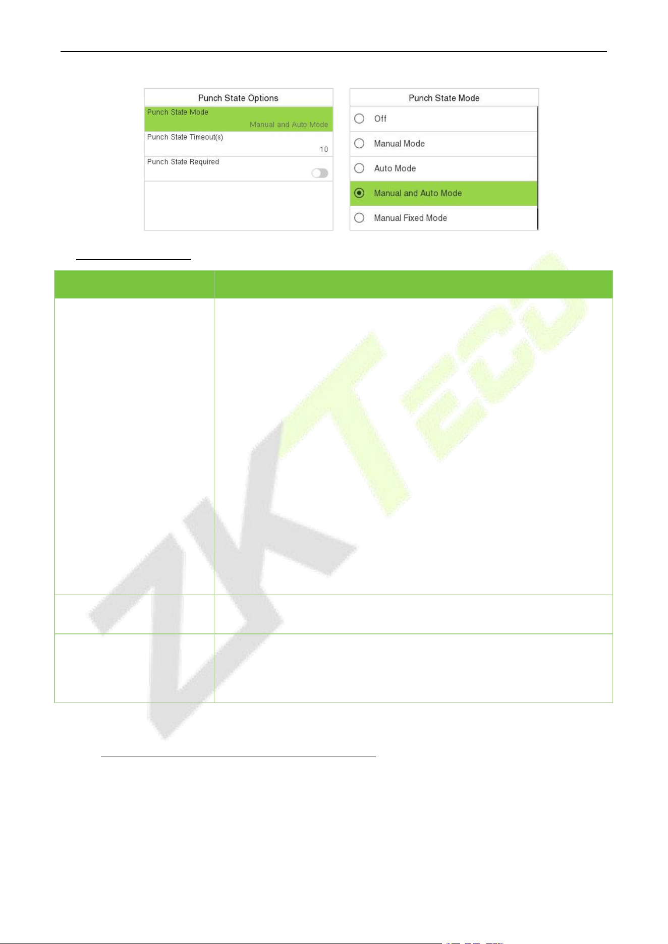
F34 User Manual
P a g e | 50 Copyright © 2026 ZKTECO CO., LTD. All rights reserved.
Function Description
Function Name
Description
Punch State Mode
Off: Disable the punch state function. Therefore, the punch state key set
under Shortcut Key Mappings menu will become invalid.
Manual Mode: Switch the punch state key manually, and the punch state
key will disappear after Punch State Timeout.
Auto Mode: The punch state key will automatically switch to a specific
punch status according to the predefined time schedule which can be set
in the Shortcut Key Mappings.
Manual and Auto Mode: The main interface will display the auto-switch
punch state key. However, the users will still be able to select alternative
that is the manual attendance status. After timeout, the manual switching
to punch state key will become auto-switch punch state key.
Manual Fixed Mode: After the punch state key is set manually to a
particular punch status, the function will remain unchanged until it is being
manually switched again.
Fixed Mode: Only the manually fixed punch state key will be shown. Users
cannot change the status by taping any other keys.
Punch State Timeout(s)
It is the time for which the punch state displays. The value ranges from 5 to
999 seconds.
Punch State Required
Select whether an attendance state needs to be selected after verification.
ON: Attendance state needs to be selected after verification.
OFF: Attendance state need not requires to be selected after verification.
10.5 Shortcut Key Mappings (T&A PUSH)
Users may define shortcut keys for attendance status and functional keys which will be defined on the
main interface. So, on the main interface, when the shortcut keys are tapped, the corresponding
attendance status or the function interface will be displayed directly.
Select Shortcut Key Mappings on the Personalize interface to set the required shortcut keys.
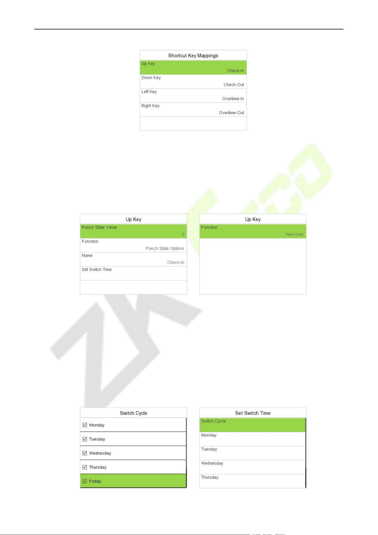
F34 User Manual
P a g e | 51 Copyright © 2026 ZKTECO CO., LTD. All rights reserved.
On the Shortcut Key Mappings interface, select the required shortcut key to configure the
shortcut key settings.
On the Shortcut Key (example, "Up Key") interface, select Function to set the functional process
of the shortcut key either as punch state key or function key.
If the Shortcut key is defined as a function key (such as New user, All users, etc.), the configuration
is completed as shown in the image below.
If the Shortcut key is set as a punch state key (such as check in, check out, etc.), then it is required
to set the punch state value (valid value 0 to 250), name.
Set the Switch Time
The switch time is set in accordance with the punch state options.
When the Punch State Mode is set to Auto Mode, the switch time should be set.
On the Shortcut Key interface, select Set Switch Time to set the switch time.
On the Switch Cycle interface, select the switch cycle (Monday, Tuesday, etc.) as shown in the
image below.
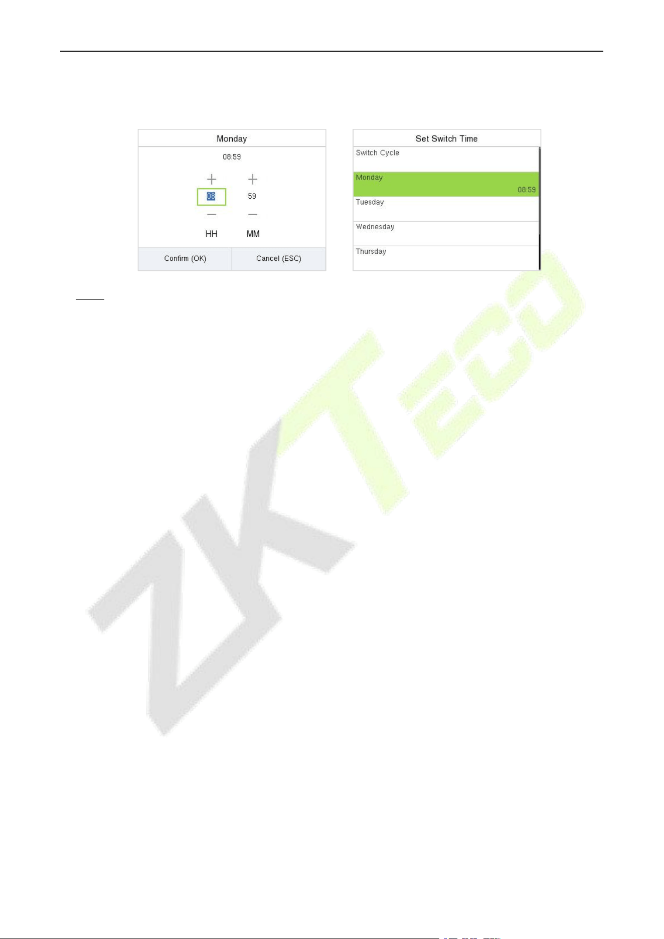
F34 User Manual
P a g e | 52 Copyright © 2026 ZKTECO CO., LTD. All rights reserved.
Once the Switch cycle is selected, set the switch time for each day, and press M/OK to confirm, as
shown in the image below.
Note: When the function is set to Undefined, the device will not enable the punch state key.
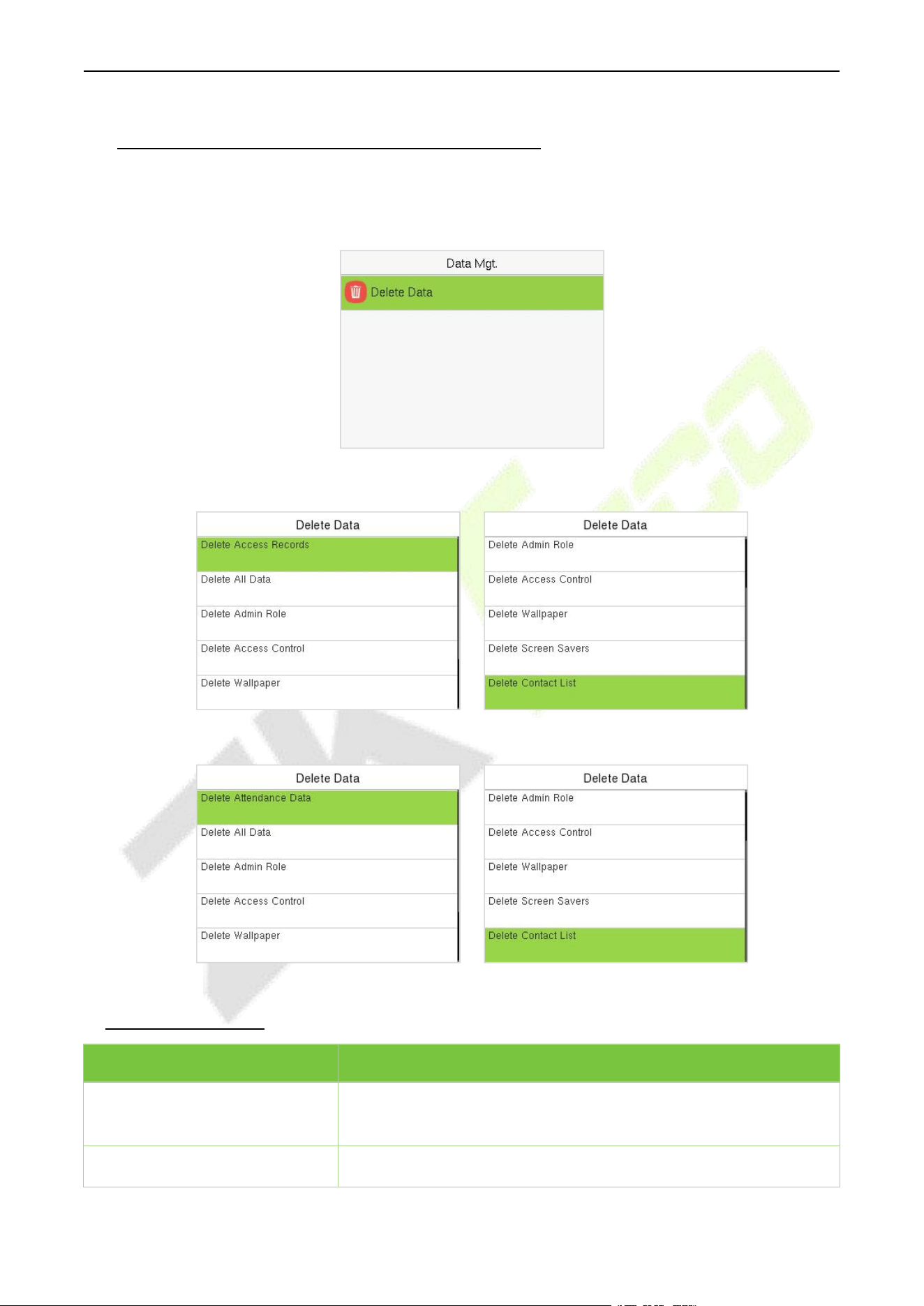
F34 User Manual
P a g e | 53 Copyright © 2026 ZKTECO CO., LTD. All rights reserved.
11 Data Management (PUSH Protocol)
When the device is on the initial interface, press [M/OK] button and enter Data Mgt. to manage the
relevant data in the device.
Select Delete Data on the Data Mgt. interface to delete the required data.
A&C PUSH
T&A PUSH
Function Description
Function Name
Description
Delete Access Records /
Attendance Data
To delete the access records / attendance data conditionally.
Delete All Data
To delete the information and access records / attendance data of
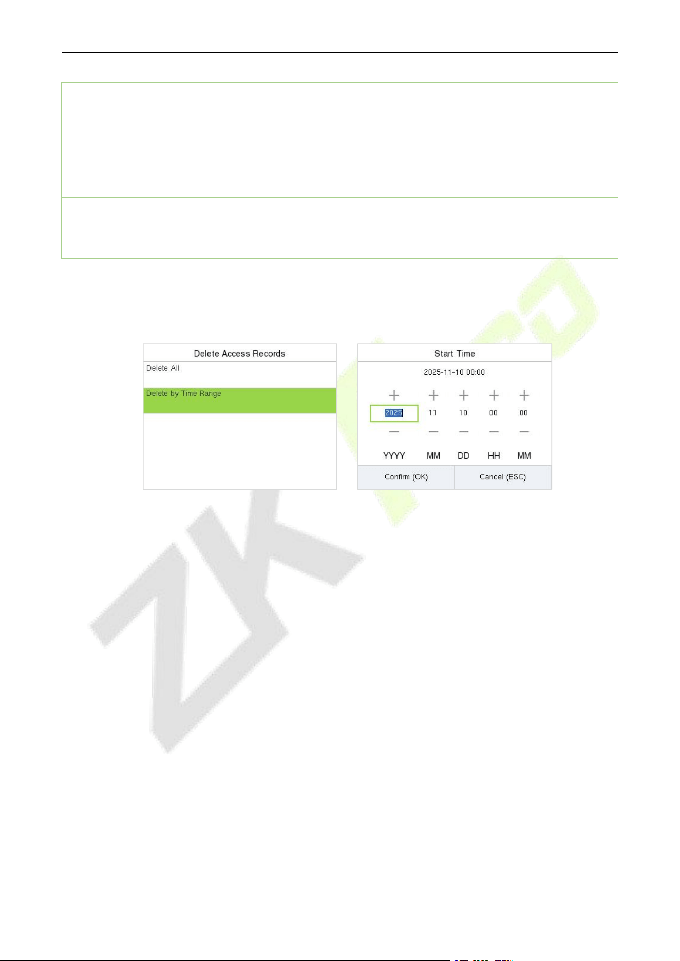
F34 User Manual
P a g e | 54 Copyright © 2026 ZKTECO CO., LTD. All rights reserved.
all registered users.
Delete Admin Role
To remove all the administrator privileges.
Delete Access Control
To delete all the access data.
Delete Wallpaper
To delete all the wallpapers in the device.
Delete Screen Savers
To delete all the screen savers in the device.
Delete Contact List
To delete all the contact list in the device.
The user may select Delete All or Delete by Time Range when deleting the access records /
attendance data, to Delete by Time Range, you need to set a specific time range to delete all data
within a specific period.
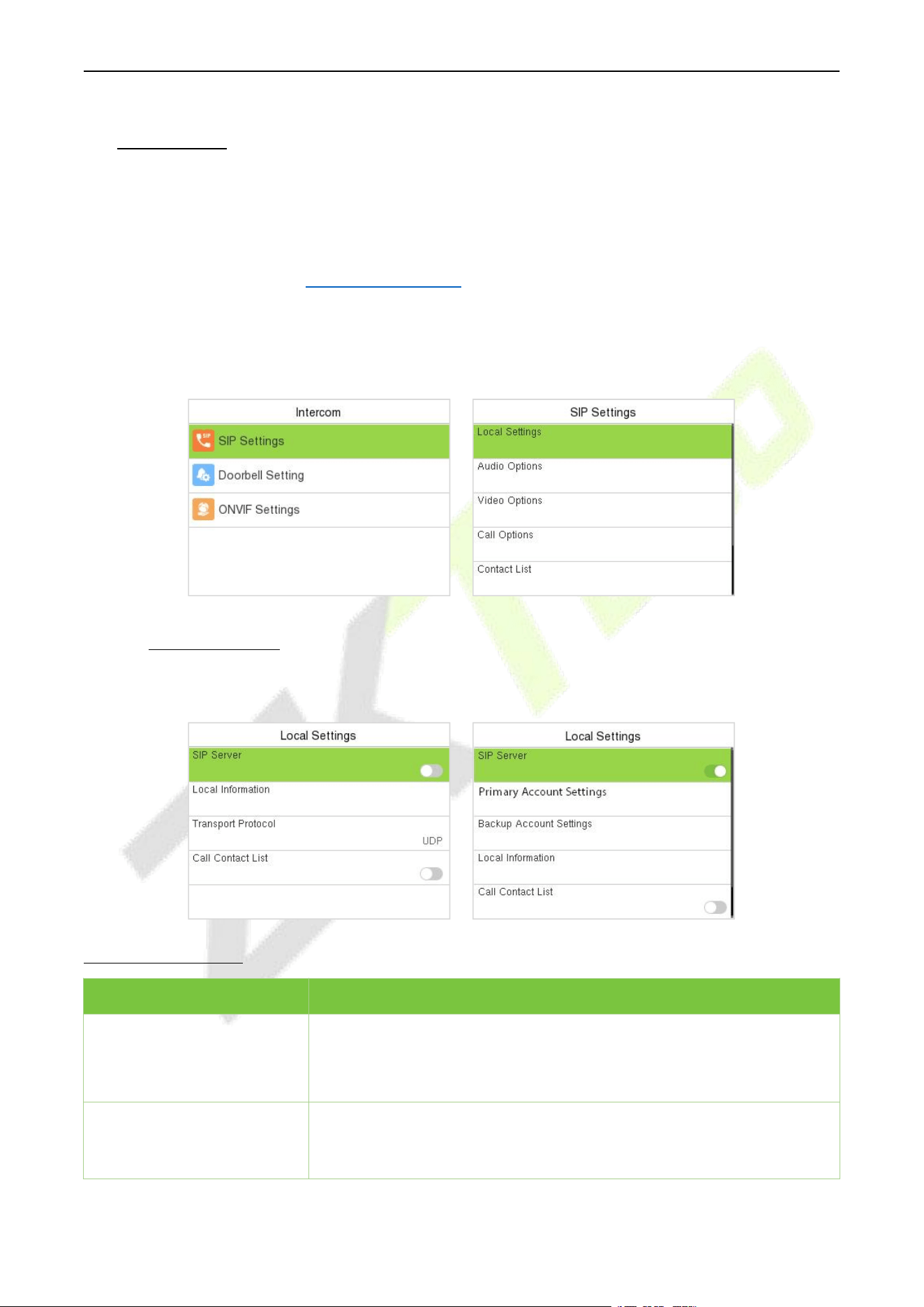
F34 User Manual
P a g e | 55 Copyright © 2026 ZKTECO CO., LTD. All rights reserved.
12 Intercom
When the device is on the initial interface, press M/OK and select Intercom to set relevant parameters
of intercom, including SIP, Doorbell and ONVIF Settings.
The device achieves video intercom there are two modes, respectively, the LAN and SIP server. For
more details, please refer to 26 SIP Video Intercom.
12.1 SIP Settings
Select SIP Settings on the Intercom interface to configure the settings.
12.1.1 Local Settings
Select Local Settings on the SIP Settings interface.
Function Description
Function Name
Description
SIP Server
Select whether to enable the SIP server. When it is enabled, the SIP
account needs to be set.
Note: Every time this feature is turned on or off, the contact list will be
reset.
Primary Account Settings
After assigning the SIP account to the device on the ZKBio CVAccess, the
account information will be automatically synchronized to the device.
You don’t need to configure it manually.
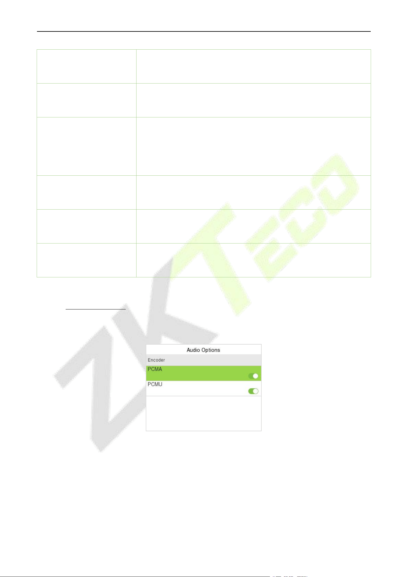
F34 User Manual
P a g e | 56 Copyright © 2026 ZKTECO CO., LTD. All rights reserved.
Backup Account Settings
Select whether to enable the backup account settings.
Device Port
When using a local area network for intercom, enter the device port
number.
Local Information
Device Type: Set the device type as Entrance Station or Fence
Terminal. And set the specific location information of the device,
including the block, unit (can be disabled), and room number. When it is
set as Fence Terminal, the call page will display block, unit and room
number.
Note: The contact list will be cleared after changing the device type.
Transport Protocol
Set the transport protocol between the device and indoor monitor.
Call Contact List
Select whether to enable the contact list on the call page. When it is
enabled, you can press the Up Key to open the contact list on the call
page.
Call Number Type
Room Number: The device can call the extension number (short
number) or room number.
SIP Account Number: The device can only call the SIP account.
12.1.2 Audio Options
Select Audio Options on the SIP Settings interface.
Select the audio encoder for intercom. Both PCMU and PCMA provide better voice quality, but they take
up more bandwidth, requiring 64kbps.
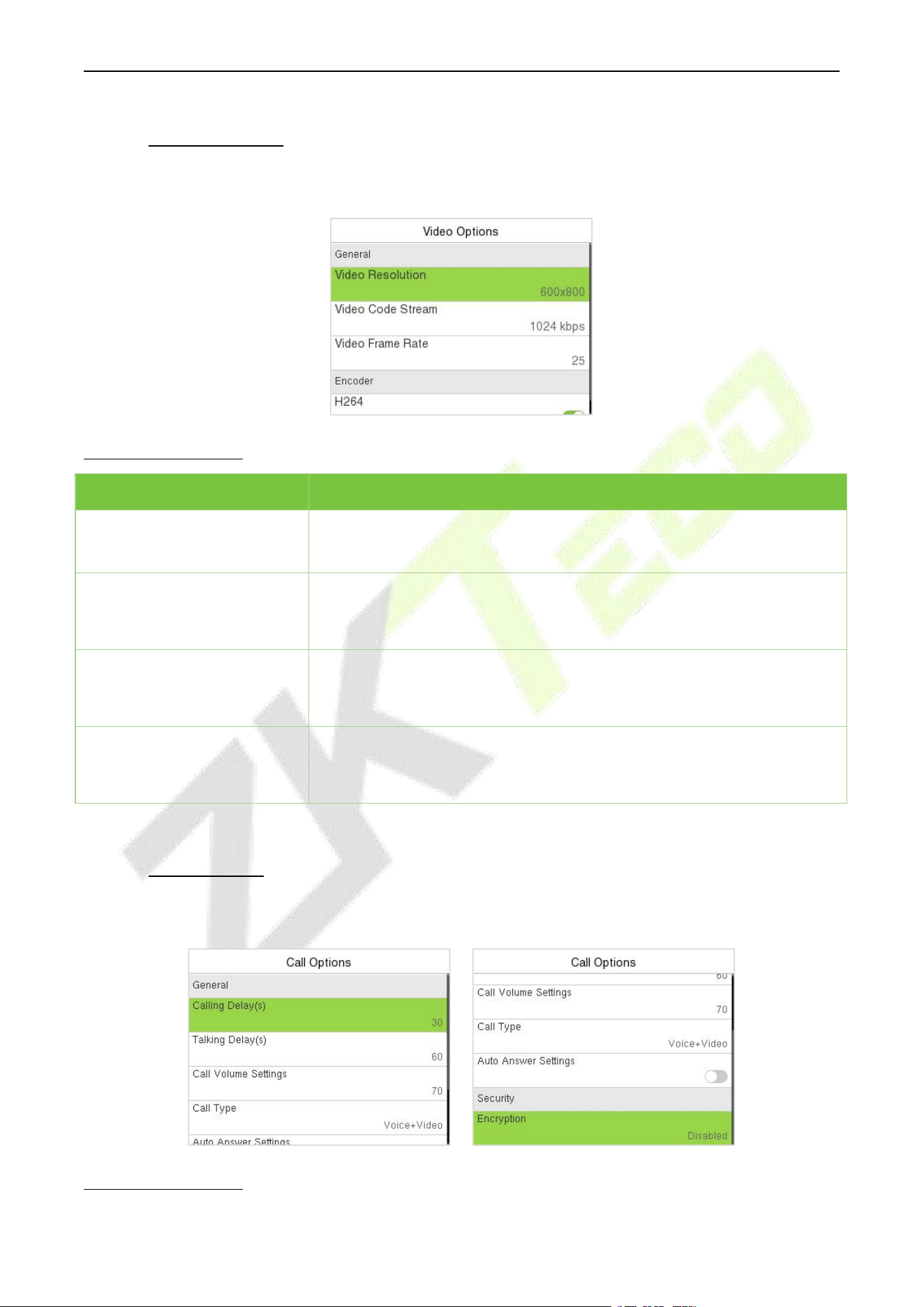
F34 User Manual
P a g e | 57 Copyright © 2026 ZKTECO CO., LTD. All rights reserved.
12.1.3 Video Options
Select Video Options on the SIP Settings interface.
Function Description
Function Name
Description
Video Resolution
Select the video resolution of the intercom, 1024 x 576 or 800 x 600. The
device only supports landscape screen. It is suggested to set as 800 x 600.
Video Code Stream
Select the video code stream of the intercom, the larger the value, the
higher the picture and sound quality of the video, and the greater the
network requirements.
Video Frame Rate
Refers to the number of frames per second of the intercom video display,
the larger the value the smoother, the device defaults to 25Hz, does not
support modification.
Encoder
Whether to enable H264 Encoder.
12.1.4 Call Options
Select Call Options on the SIP Settings interface.
Function Description
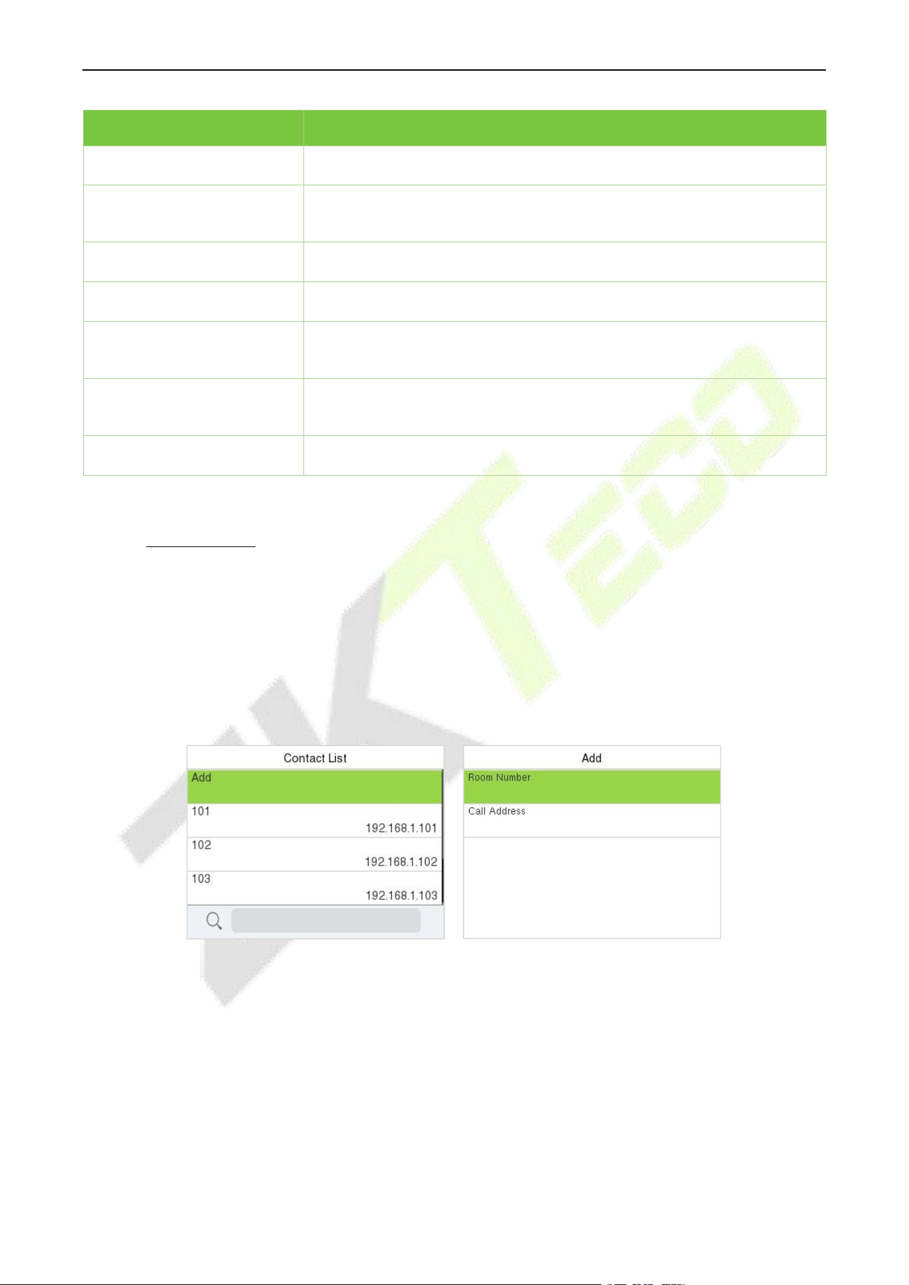
F34 User Manual
P a g e | 58 Copyright © 2026 ZKTECO CO., LTD. All rights reserved.
Function Name
Description
Calling Delay(s)
Set the time of call, valid value 30 to 60 seconds.
Talking Delay(s)
Set the time of intercom, valid value 60 to 120 seconds. It is suggested
to set as 60s.
Call Volume Settings
Set the volume of the call, with valid value ranging from 0 to 100.
Call Type
Set the call type to Voice only or Voice+Video.
Auto Answer Settings
Select whether to enable the auto answer function. When it is enabled,
the device will automatically answer if the indoor monitor calls.
Auto-Answer Delay Time
The device will automatically answer after the set delay time if the
indoor monitor calls, valid value 0 to 10 seconds.
Encryption
It is disabled by default.
12.1.5 Contact List
Select Contact List on the SIP Settings interface.
In SIP Server mode, the contact list is synchronized by the ZKBio CVAccess Server to the device. The
contact list can only be viewed, cannot be edited. When the SIP server is disabled, the room number and
call address of the indoor monitors can be added here.
Select Add to enter the Add Contact List interface.
Room Number: Customize the number of the indoor monitor.
When the device type is set as Entrance Station, the room number can be 1~ 4 digits. When the device
type is set as Fence Terminal, you need to input the block, unit and room number. For example, if the
indoor monitor is in Block 3, Unit 2, Room 2601, then input “03.02.2601”.
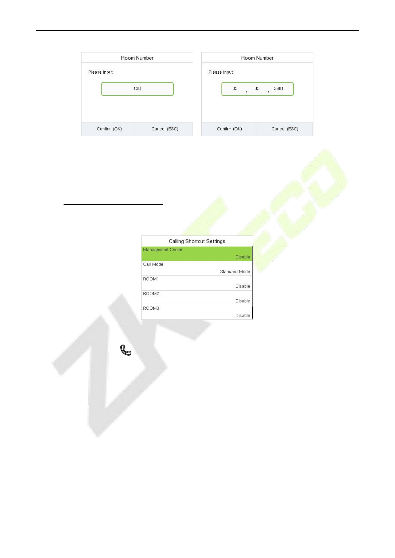
F34 User Manual
P a g e | 59 Copyright © 2026 ZKTECO CO., LTD. All rights reserved.
Entrance Station Fence Terminal
Call Address: It is the IP Address of the indoor monitor.
12.1.6 Calling Shortcut Settings
Select Calling Shortcut Settings on the SIP Settings interface.
Management Center: Select whether to enable the Management Center and set its number. After
enabling, you can press the key to directly call the admin on the call page.
Call Mode: It can be set as Standard Mode or Direct Calling Mode.
In Standard mode, there are 4 shortcut keys that can be enabled and defined in the device: ROOM1,
ROOM2, ROOM3 and ROOM4. You can set a shortcut key to call the indoor monitor quickly without
entering the number of the indoor monitor each time.
Name: Customize the name of the shortcut keys.
Number: Select the room number that set in the Contact List Menu.
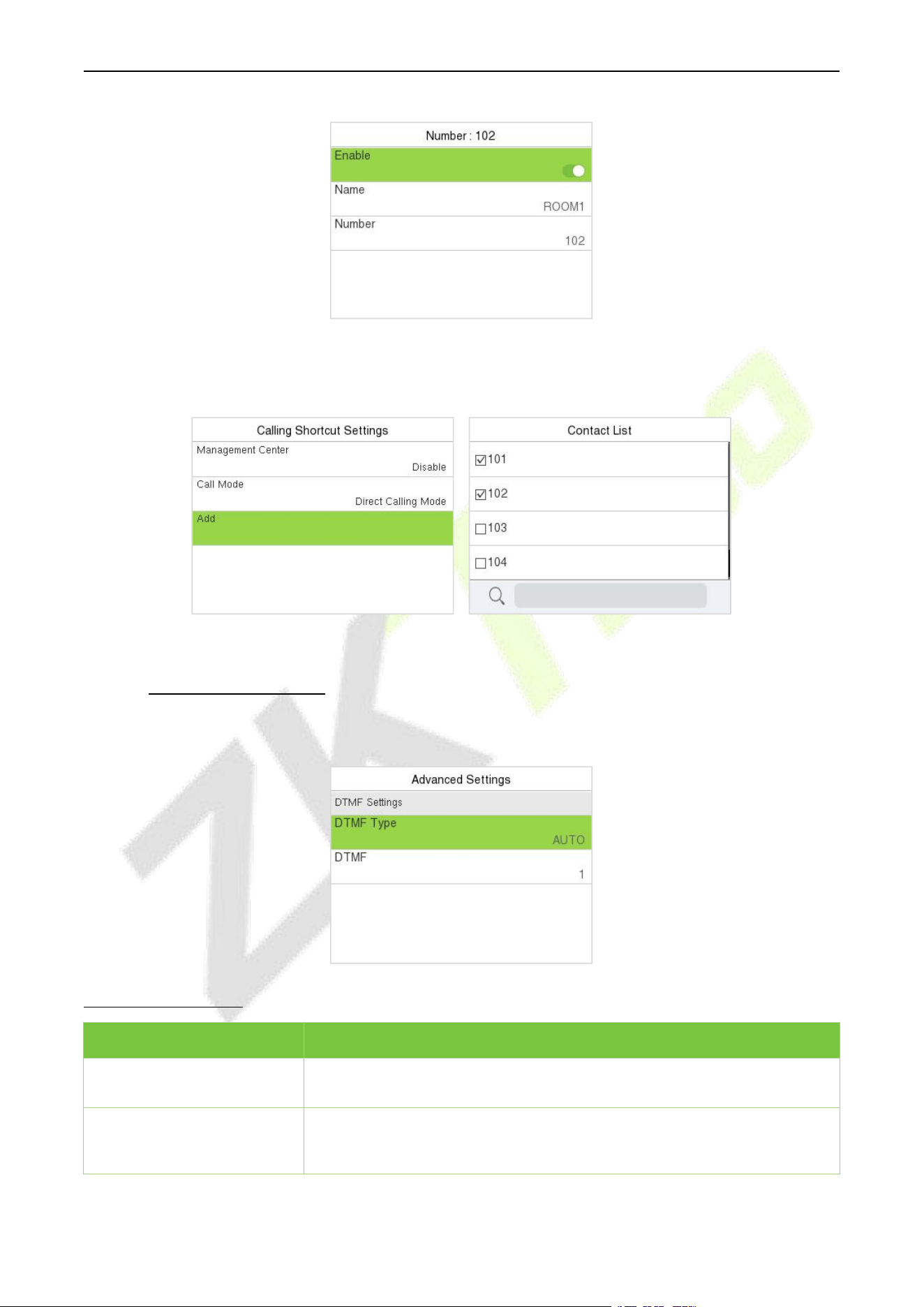
F34 User Manual
P a g e | 60 Copyright © 2026 ZKTECO CO., LTD. All rights reserved.
In Direct Calling mode, the user can call multiple indoor monitors directly.
Enter Call Mode > Direct Calling Mode> Add, select the indoor monitors that you want to call, then
the indoor monitors will be displayed in the list.
12.1.7 Advanced Settings
Select Advanced Settings on the SIP Settings interface.
Function Description
Function Name
Description
DTMF Type
Set the DTMF type as AUTO, SIP INFO or RFC2833.
DTMF
The value should be set as same as the value of DTMF in the indoor
monitor.
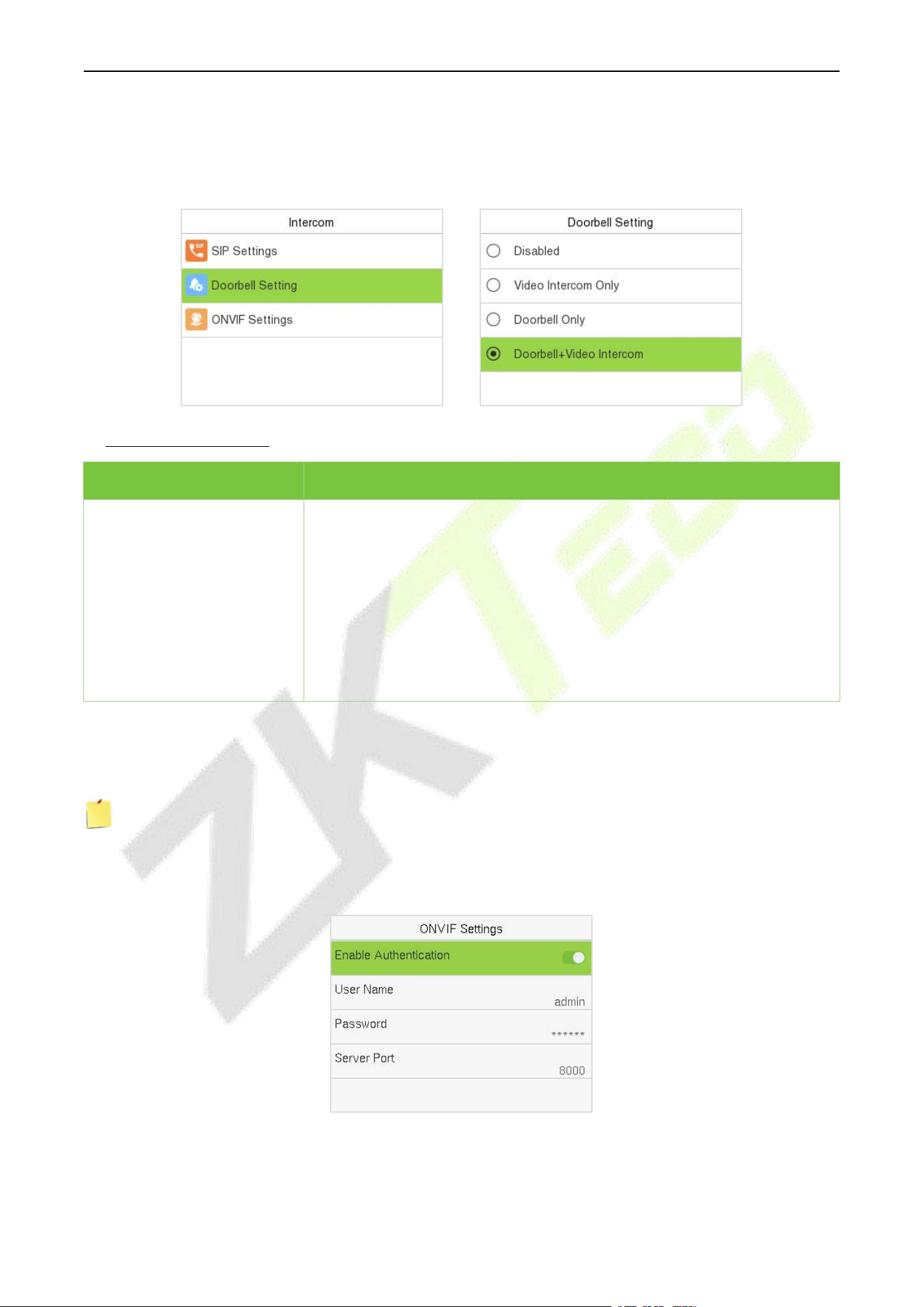
F34 User Manual
P a g e | 61 Copyright © 2026 ZKTECO CO., LTD. All rights reserved.
12.2 Doorbell Setting
Select Doorbell Setting on the Intercom interface to set the doorbell.
Function Description:
Function Name
Description
Doorbell Setting
Disabled: The doorbell button is disabled.
Doorbell Only: When the user presses the doorbell button, only the
doorbell rings.
Video Intercom Only: When the user presses the doorbell button, only
the device makes a call.
Doorbell+Video Intercom: When the user presses the doorbell button,
the doorbell rings and the device makes a call at the same time.
12.3 ONVIF Settings
Note: This function needs to be used with the network video recorder (NVR).
1. Set the device to the same network segment as the NVR.
2. Select ONVIF Settings on the Intercom interface.
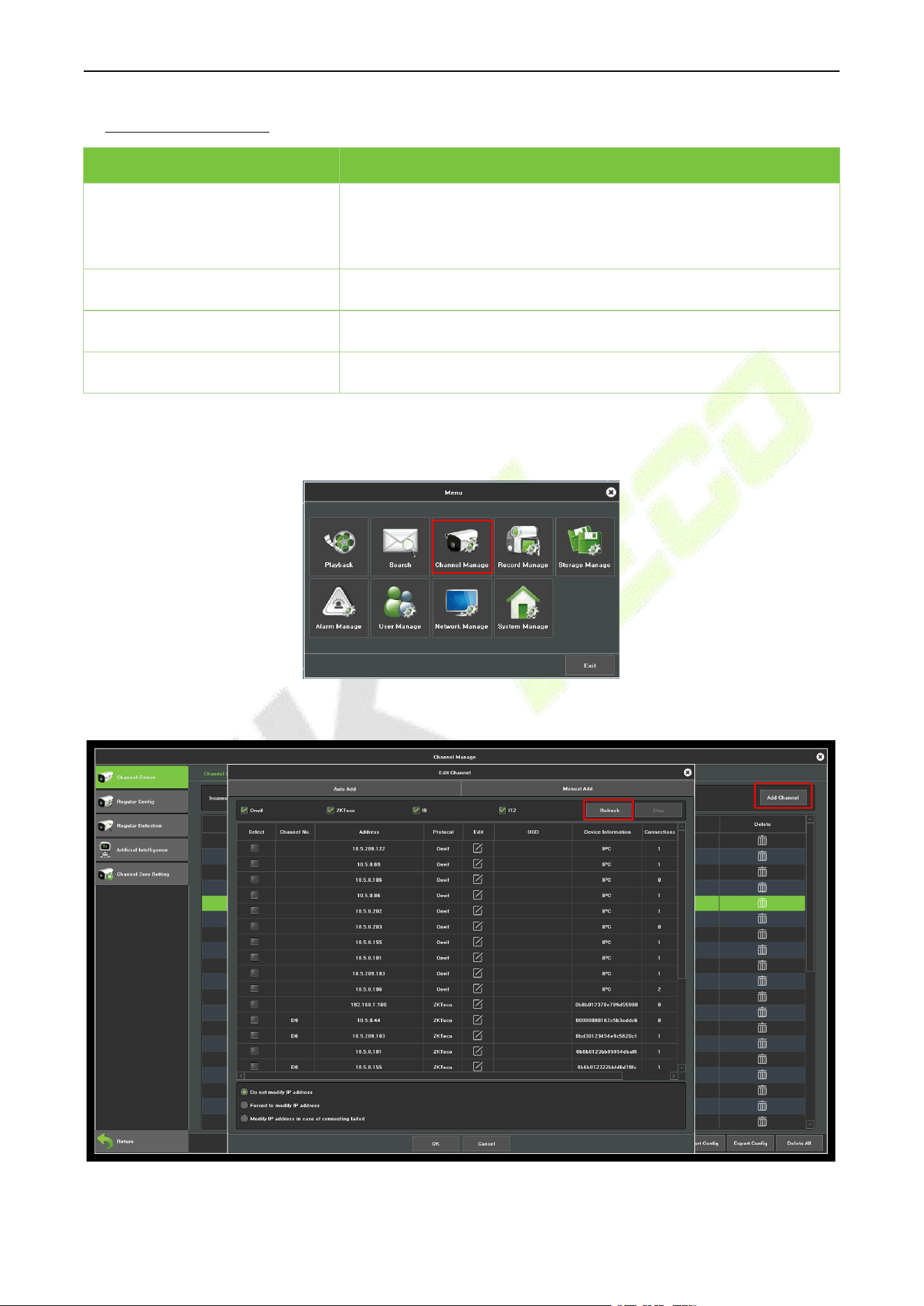
F34 User Manual
P a g e | 62 Copyright © 2026 ZKTECO CO., LTD. All rights reserved.
Function Description:
Function Name
Description
Enable Authentication
Enable/Disable the Authentication Function. When it is disabled,
there is no need to input the User Name and Password when adding
the device to the NVR.
User Name
Set the User Name. The default is admin.
Password
Set the password. The default is admin@123.
Server Port
The default is 8000, and cannot be modified.
3. On the NVR system, click on [Start] > [Menu], then the main menu will pop up.
4. Click [Channel Manage] > [Add Channel] > [Refresh] to search for the device.
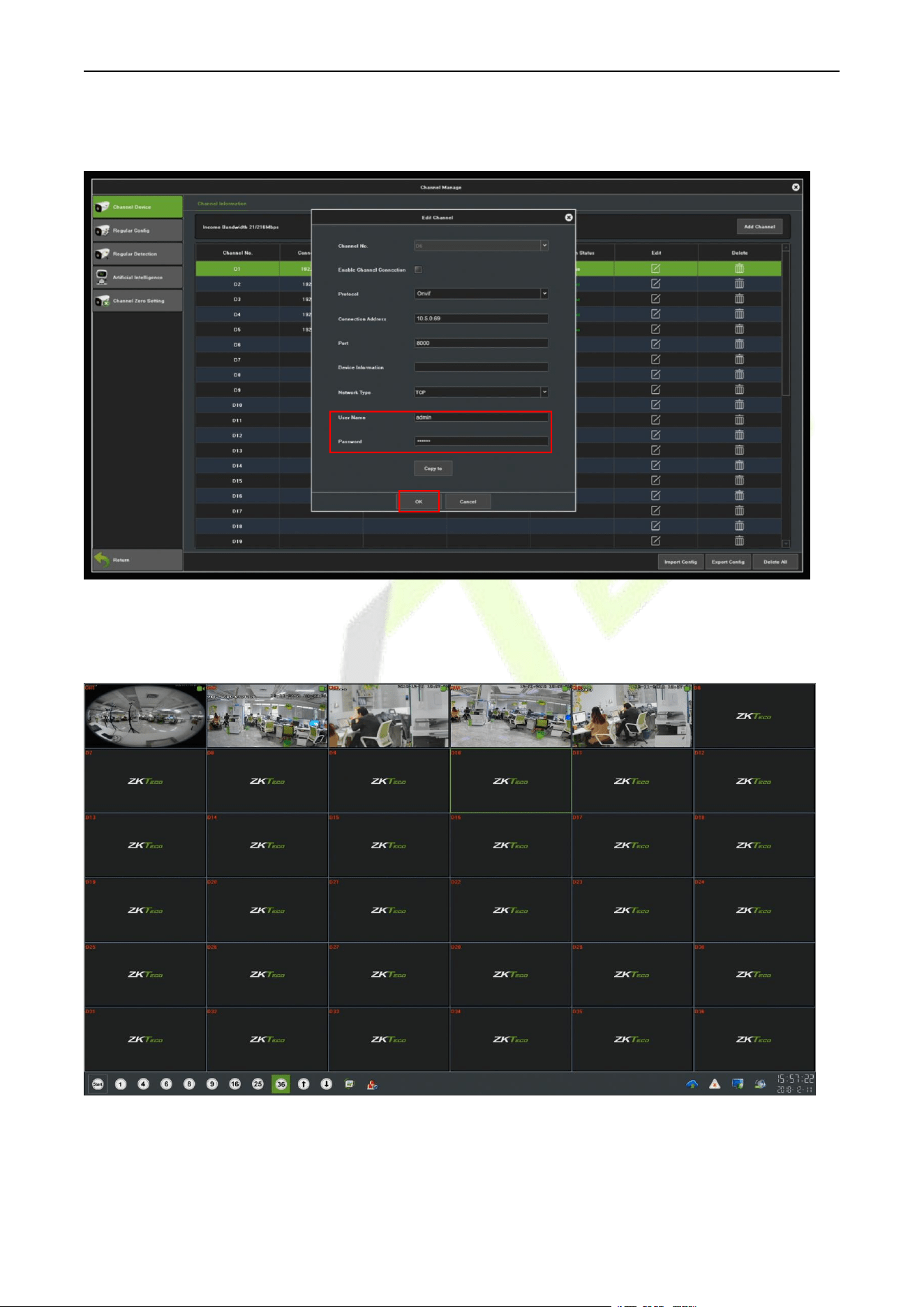
F34 User Manual
P a g e | 63 Copyright © 2026 ZKTECO CO., LTD. All rights reserved.
5. Select the checkbox for the device you want to add and edit the parameters in the corresponding text
field, then click on OK to add it to the connection list.
Note: The User Name and Password is set in the ONVIF Settings of the device.
6. After adding successfully, the video image obtaining from the device can be viewed in real-time.
For more details, please refer to the NVR User Manual.
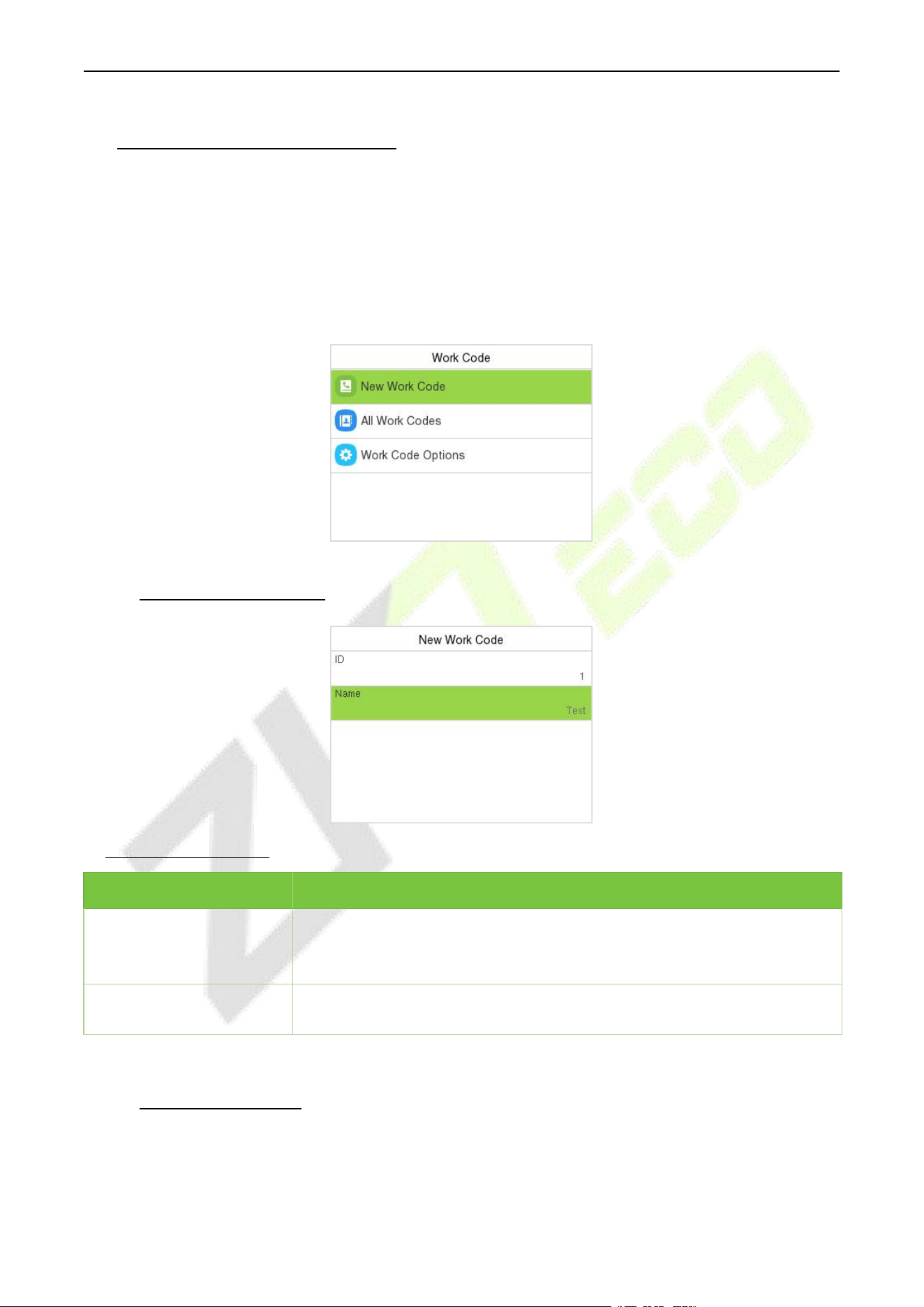
F34 User Manual
P a g e | 64 Copyright © 2026 ZKTECO CO., LTD. All rights reserved.
13 Work Code (T&A PUSH)
Employees’ salaries are subject to their attendance records. An employee can be engaged in more than
one type of work which may vary with time. As the pay varies according to the work types, the terminal
provides a parameter to indicate the corresponding work type for every attendance record to facilitate
rapid understanding of different attendance situations during the handling of attendance data.
Select Work Code on the main menu interface. It is only for time attendance terminal.
13.1 Add a Work Code
Function Description:
Function Name
Description
ID
It is the digital code of the work code. Users may set a valid value between
1 and 99999999.
Name
It is the naming of the work code.
13.2 All Work Codes
You can view, edit and delete work codes in All Work Codes. The process of editing a work code is the
same as adding a work code, except that the ID is not allowed to be modified.
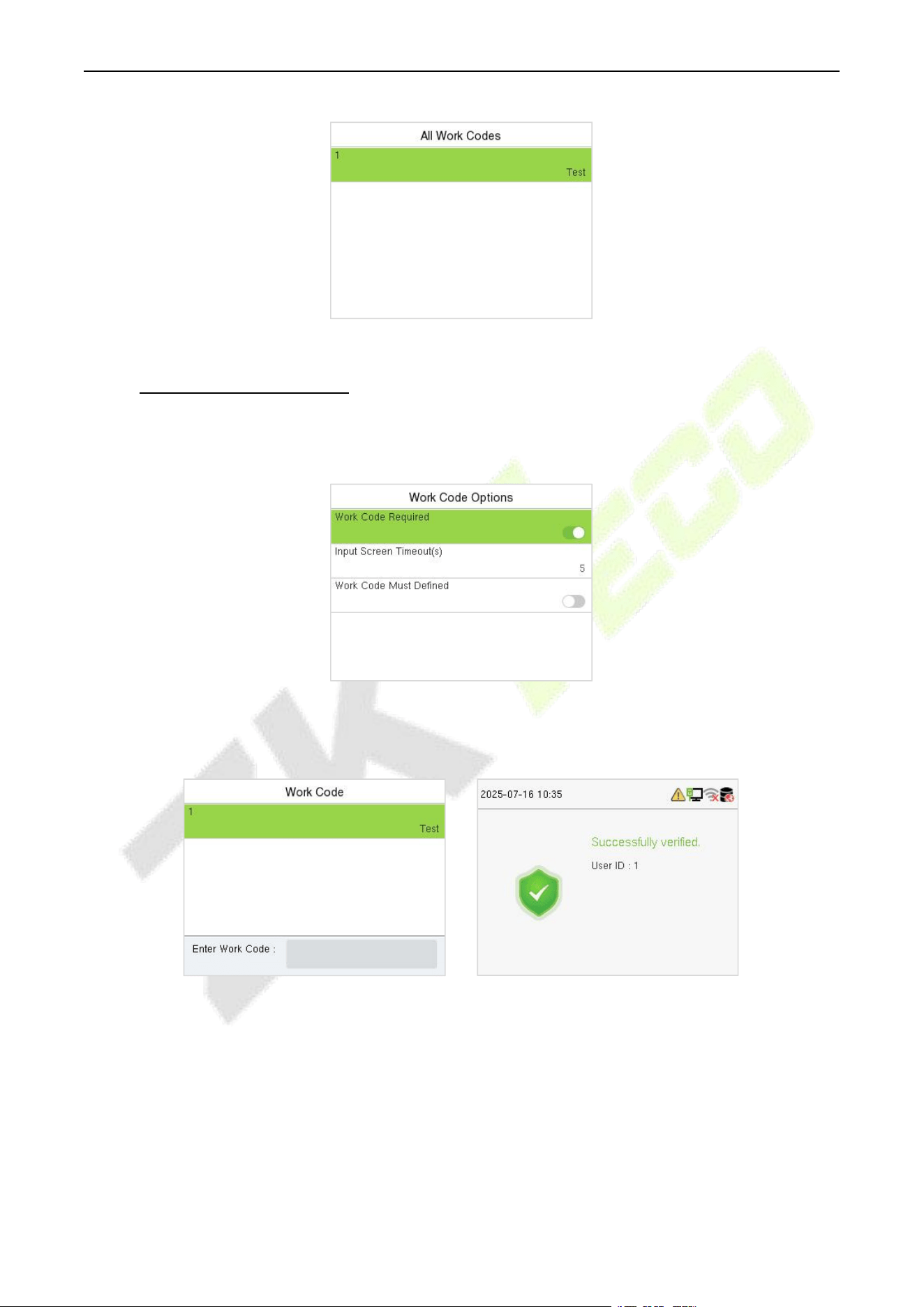
F34 User Manual
P a g e | 65 Copyright © 2026 ZKTECO CO., LTD. All rights reserved.
13.3 Work Code Options
To set whether entering the work code is a must and whether the entered work code must exist during
authentication.
In 1: N or 1:1 verification, the system will automatically pop up the following window. Select the
corresponding Word Code manually to verify successfully.
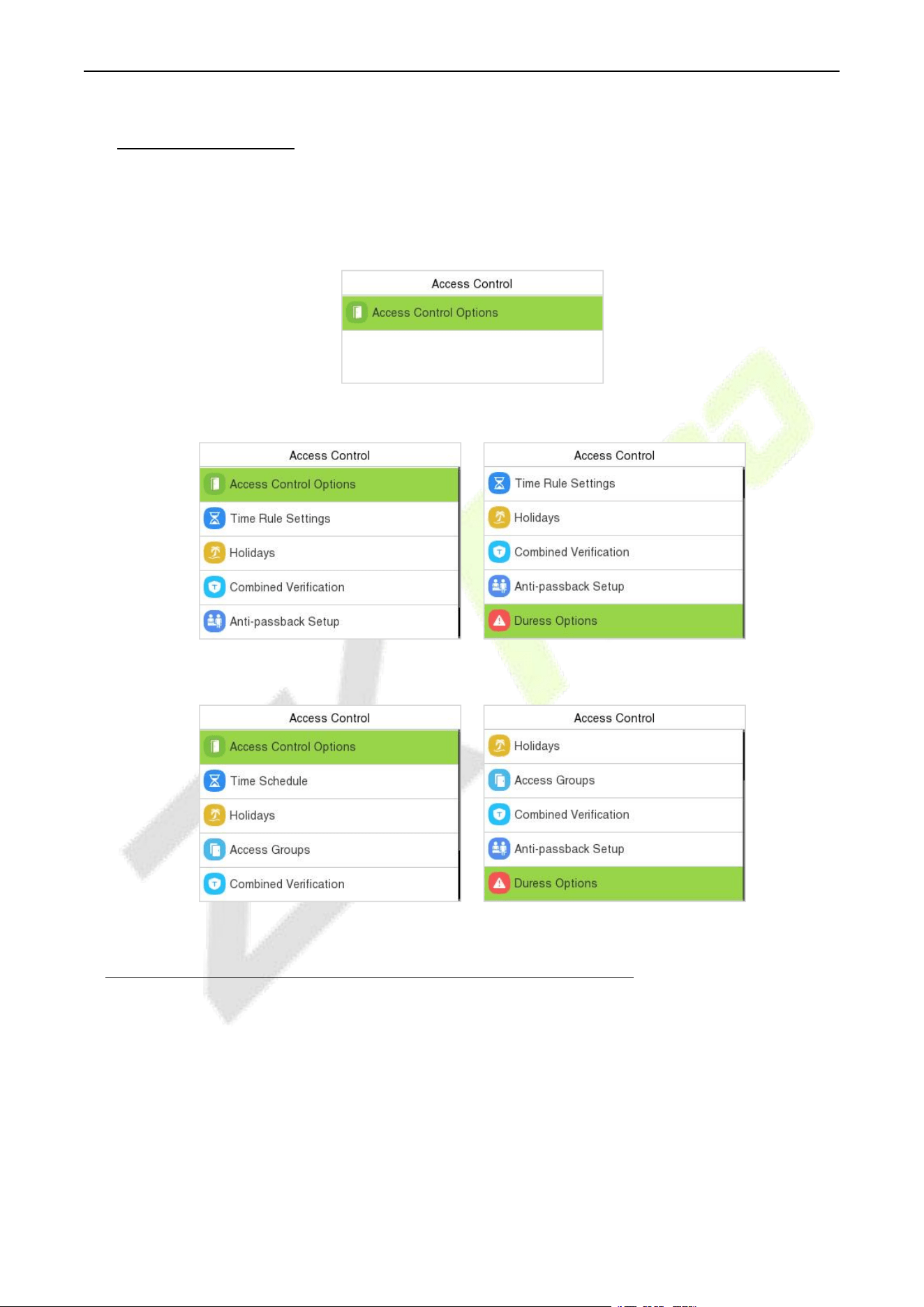
F34 User Manual
P a g e | 66 Copyright © 2026 ZKTECO CO., LTD. All rights reserved.
14 Access Control
When the device is on the initial interface, press [M/OK] button and enter Access Control to set the
schedule of the door opening, locks control and to configure other parameters settings related to
access control.
BEST Protocol
A&C PUSH
T&A PUSH
To get access, the registered user must meet the following conditions:
1. The relevant door’s current unlock time should be within any valid time zone of the user’s time
period.
2. The corresponding user’s group must be already set in the door unlock combination (and if there
are other groups, being set in the same access combo, then the verification of those group’s
members is also required to unlock the door).
3. In default settings, new users are allocated into the first group with the default group time zone,
where the access combo is "1" and is set in unlock state by default.
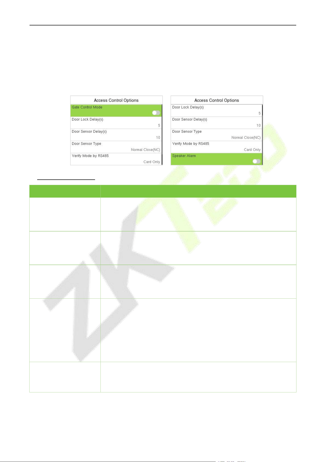
F34 User Manual
P a g e | 67 Copyright © 2026 ZKTECO CO., LTD. All rights reserved.
14.1 Access Control Options
Select Access Control Options on the Access Control interface to set the parameters of the control
lock of the terminal and related equipment.
BEST Protocol:
Function Description:
Function Name
Description
Gate Control Mode
It toggles between ON or OFF switch to get into gate control mode or not.
When set to ON, the interface removes the Door Lock Delay, Door Sensor
Delay, and Door Sensor Type options.
Door Lock Delay (s)
The length of time that the device controls the electric lock to be in unlock
state.
Valid value: 1~99 seconds.
Door Sensor Delay (s)
If the door is not locked and is left open for a certain duration (Door Sensor
Delay), an alarm will be triggered.
The valid value of Door Sensor Delay ranges from 1 to 255 seconds.
Door Sensor Type
There are three Sensor types: None, Normal Open, and Normal Close.
None: It means the door sensor is not in use.
Normal Open: It means the door is always left open when electric power is
on.
Normal Close: It means the door is always left closed when electric power
is on.
Speaker Alarm
It transmits a sound alarm or disassembly alarm from the local. When the
door is closed or the verification is successful, the system cancels the alarm
from the local.
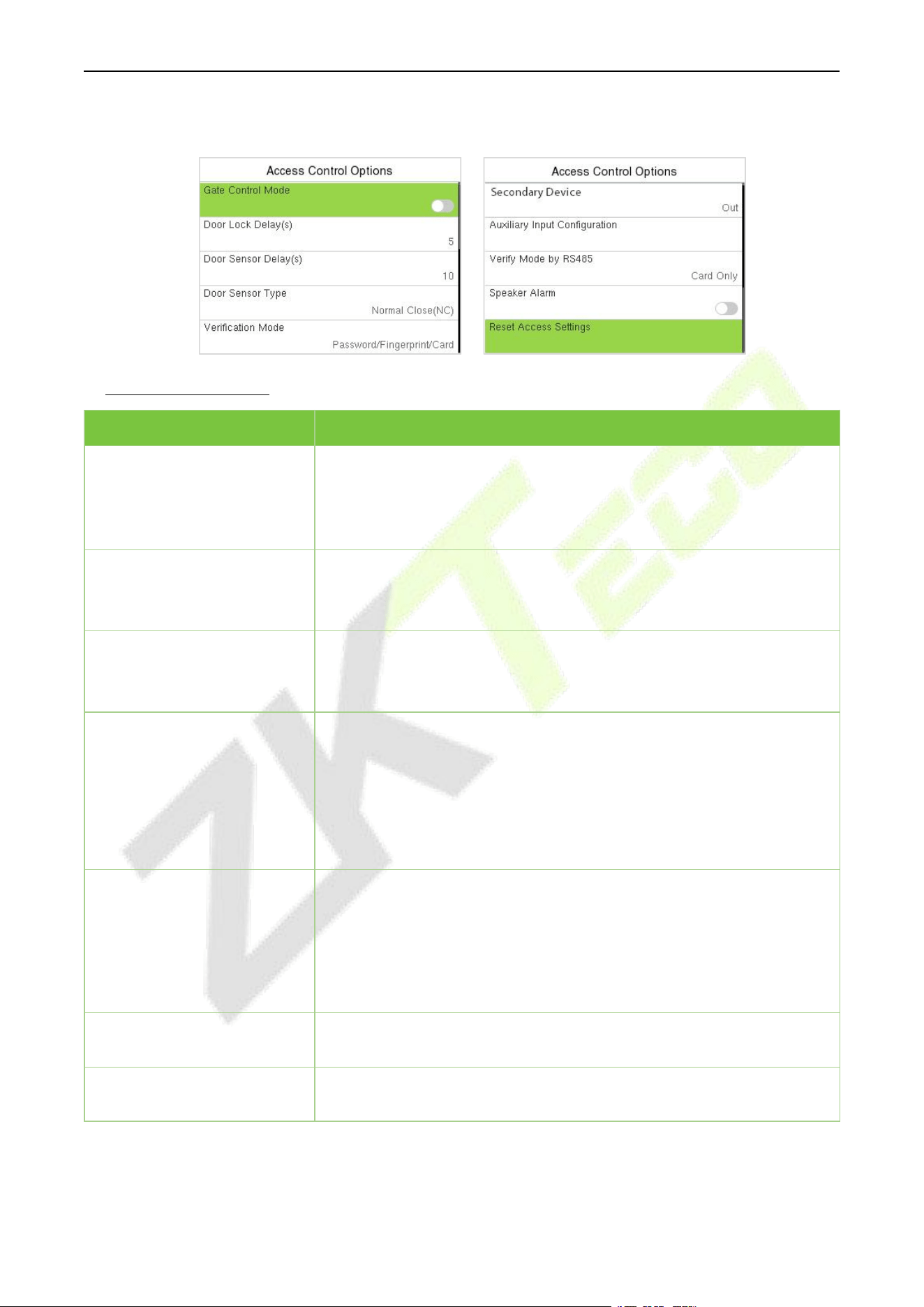
F34 User Manual
P a g e | 68 Copyright © 2026 ZKTECO CO., LTD. All rights reserved.
A&C PUSH:
Function Description:
Function Name
Description
Gate Control Mode
It toggles between ON or OFF switch to get into gate control mode or
not.
When set to ON, the interface removes the Door Lock Delay, Door
Sensor Delay, and Door Sensor Type options.
Door Lock Delay (s)
The length of time that the device controls the electric lock to be in
unlock state.
Valid value: 1~99 seconds.
Door Sensor Delay (s)
If the door is not locked and is left open for a certain duration (Door
Sensor Delay), an alarm will be triggered.
The valid value of Door Sensor Delay ranges from 1 to 255 seconds.
Door Sensor Type
There are three Sensor types: None, Normal Open, and Normal Close.
None: It means the door sensor is not in use.
Normal Open: It means the door is always left open when electric
power is on.
Normal Close: It means the door is always left closed when electric
power is on.
Verification Mode
The supported verification mode includes Password/Fingerprint/Card,
Fingerprint Only, User ID Only, Password, Card Only,
Fingerprint/Password, Fingerprint/Card, User ID + Fingerprint,
Fingerprint + Password, Fingerprint + Card, Fingerprint + Password +
Card, Password + Card, Password/Card, User ID + Fingerprint +
Password, Fingerprint + (Card/User ID).
Door Available Time Period
It sets the timing for the door so that the door is accessible only during
that period.
Normal Open Time Period
It is the scheduled time-period for "Normal Open" mode so that the
door is always open during this period.
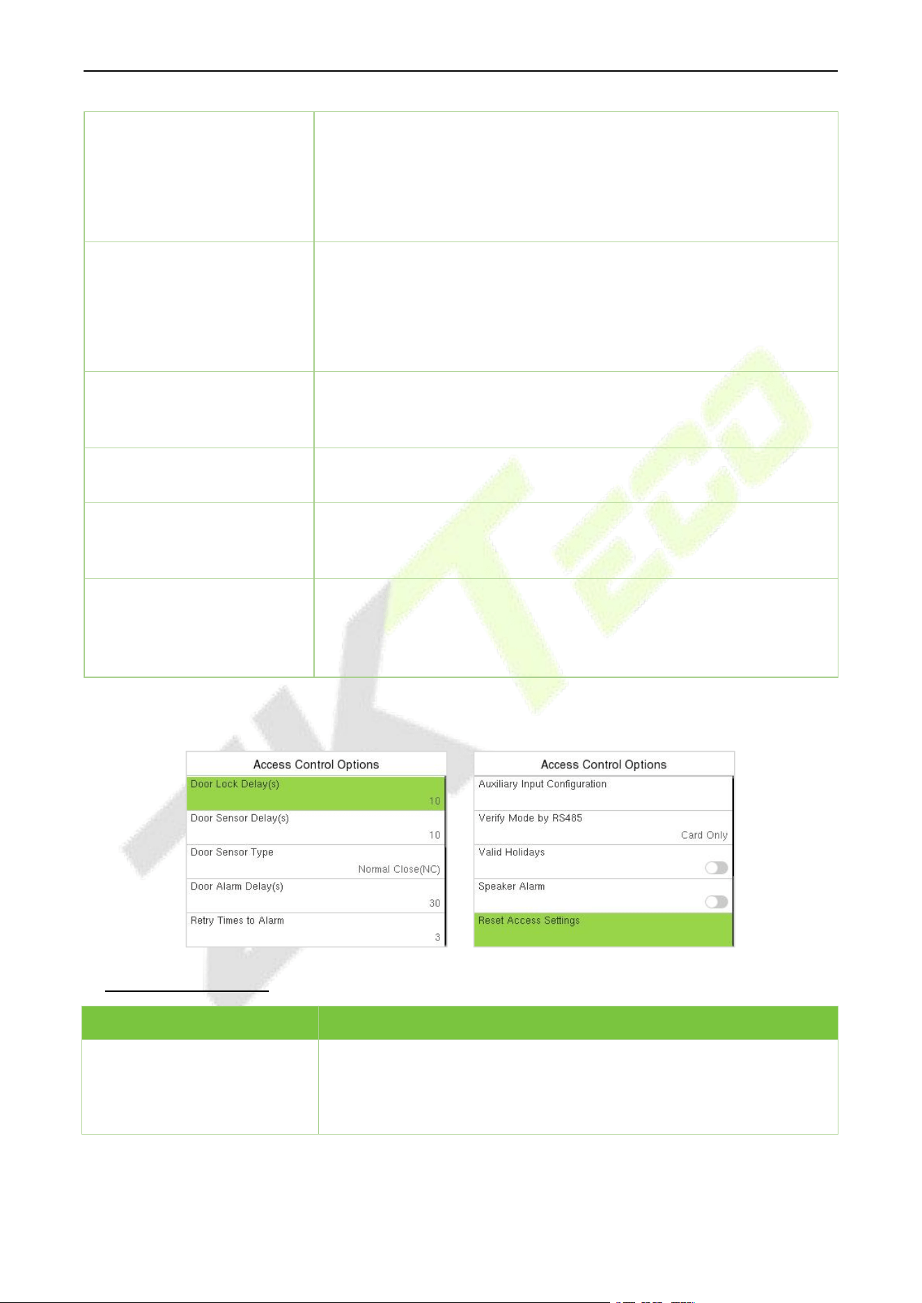
F34 User Manual
P a g e | 69 Copyright © 2026 ZKTECO CO., LTD. All rights reserved.
Primary Device
While configuring the primary and secondary devices, you may set the
state of the primary as Out or In.
Out: A record of verification on the primary device is a check-out
record.
In: A record of verification on the primary device is a check-in record.
Secondary Device
While configuring the primary and secondary devices, you may set the
state of the secondary as Out or In.
Out: A record of verification on the secondary device is a check-out
record.
In: A record of verification on the secondary device is a check-in record.
Auxiliary Input
Configuration
Sets the door unlock time period and auxiliary output type of the
auxiliary terminal device. Auxiliary output types include None, Trigger
door open, Trigger Alarm, Trigger door open and Alarm.
Verify Mode by RS485
When the RS485 reader function is turned on, the verification method is
used when the device is used as a primary or a secondary.
Speaker Alarm
It transmits a sound alarm or disassembly alarm from the local. When
the door is closed or the verification is successful, the system cancels
the alarm from the local.
Reset Access Settings
The access control reset parameters include door lock delay, door
sensor delay, door sensor type, verification mode, door available time
period, normal open time period, primary device, and alarm. However,
erased access control data in Data Mgt. is excluded.
T&A PUSH:
Function Description:
Function Name
Description
Door Lock Delay (s)
The length of time that the device controls the electric lock to be in
unlock state.
Valid value: 0 to 10 seconds.

F34 User Manual
P a g e | 70 Copyright © 2026 ZKTECO CO., LTD. All rights reserved.
Door Sensor Delay (s)
If the door is not locked and is left open for a certain duration (Door
Sensor Delay), an alarm will be triggered.
The valid value of Door Sensor Delay ranges from 1 to 255 seconds.
Door Sensor Type
There are three Sensor types: None, Normal Open, and Normal Close.
None: It means the door sensor is not in use.
Normal Open (NO): It means the door is always left open when
electric power is on.
Normal Close (NC): It means the door is always left closed when
electric power is on.
Door Alarm Delay(s)
When the state of the door sensor is inconsistent with that of the door
sensor type, alarm will be triggered after a time period; this time
period is the Door Alarm Delay (the value ranges from 1 to 999
seconds).
Retry Times to Alarm
When the number of failed verifications reach the set value (value
ranges from 1 to 9 times), the alarm will be triggered. If the set value is
None, the alarm will not be triggered after failed verification.
Normal Close Time Period
It is the scheduled time-period for "Normal Close" mode so that the
door is always closed during this period.
Normal Open Time Period
It is the scheduled time-period for "Normal Open" mode so that the
door is always open during this period.
Auxiliary Input
Configuration
Sets the door unlock time period and auxiliary output type of the
auxiliary terminal device. Auxiliary output types include None, Trigger
door open, Trigger Alarm, Trigger door open and Alarm.
Verify Mode by RS485
When the RS485 reader function is turned on, the verification method
is used when the device is used as a primary or a secondary.
Valid Holidays
To set if Normal Close Time Period or Normal Open Time Period
settings are valid in set holiday time period. Choose [ON] to enable the
set NC or NO time period in holiday.
Speaker Alarm
It transmits a sound alarm or disassembly alarm from the local. When
the door is closed or the verification is successful, the system cancels
the alarm from the local.
Reset Access Setting
The access control reset parameters include door lock delay, door
sensor delay, door sensor type, door alarm delay, normal close time
period, normal open time period, and alarm. However, erased access
control data in Data Mgt. is excluded.
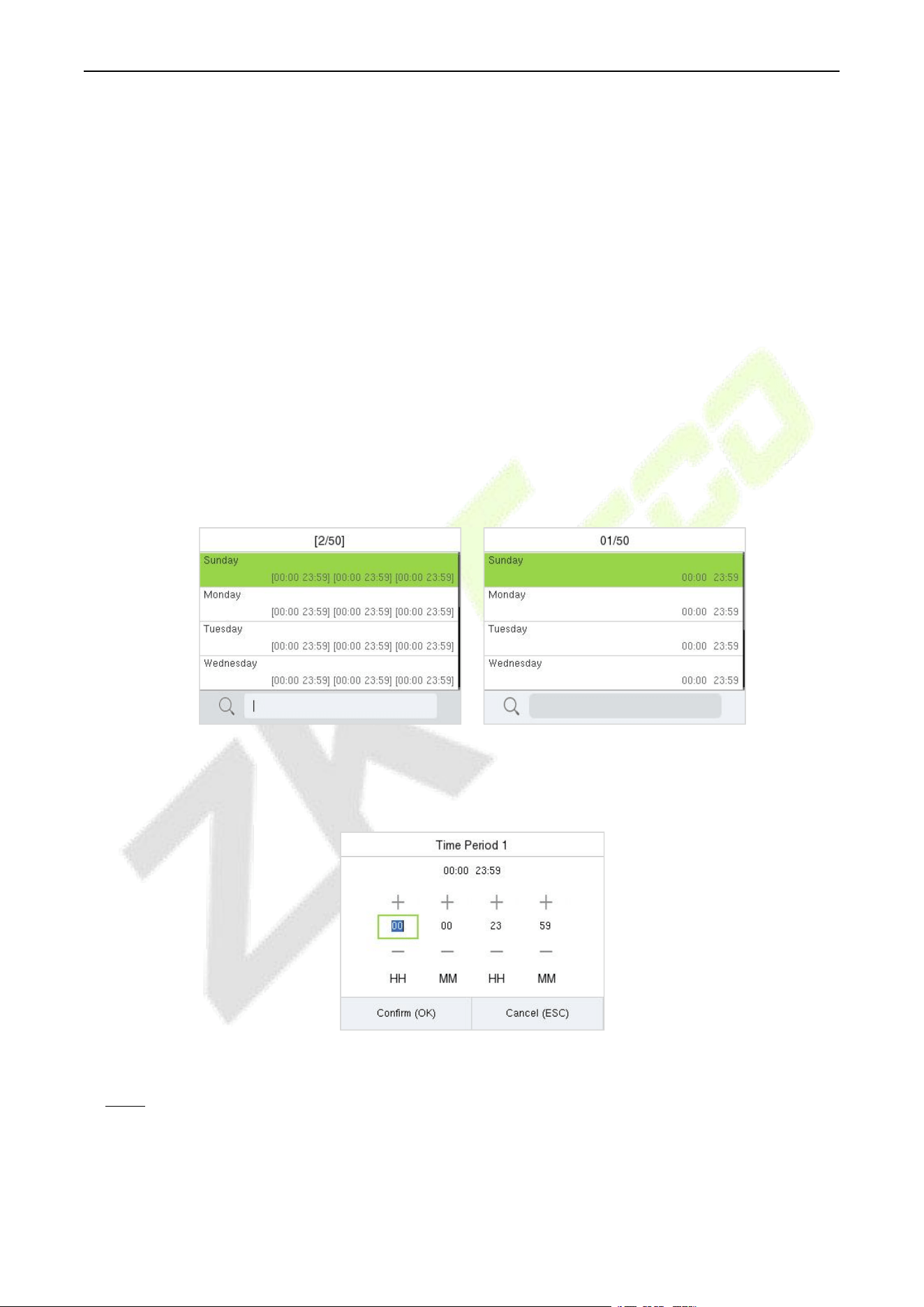
F34 User Manual
P a g e | 71 Copyright © 2026 ZKTECO CO., LTD. All rights reserved.
14.2 Time Rule Settings / Time Schedule (PUSH Protocol)
Select Time Rule Settings / Time Schedule on the Access Control interface to configure the time
settings.
The entire system can define up to 50 Time Rules.
Each time-period represents 10 Time Zones, i.e., 1 week and 3 holidays, and each time zone is a
standard 24 hour period per day and the user can only verify within the valid time-period.
One can set a maximum of 3 time periods for every time zone. The relationship among these time-
periods is "OR". Thus, when the verification time falls in any one of these time-periods, the
verification is valid.
The Time Zone format of each time-period is HH MM-HH MM, which is accurate to minutes
according to the 24-hour clock.
Search the required Time Rule in the grey box and specify the required Time Rule number (maximum
up to 50 rules).
A&C PUSH T&A PUSH
On the selected Time Rule number interface, select the required day (that is Monday, Tuesday, etc.) to
set the time.
Specify the start and the end time, and then press M/OK.
Note:
1. The door is inaccessible for the whole day when the End Time occurs before the Start Time (such as
23:57 to 23:56).
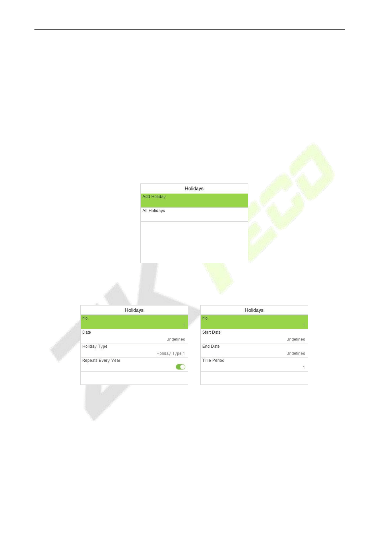
F34 User Manual
P a g e | 72 Copyright © 2026 ZKTECO CO., LTD. All rights reserved.
2. It is the time interval for valid access when the End Time occurs after the Start Time (such as 08:00
to 23:59).
3. The door is accessible for the whole day when the End Time occurs after the Start Time (such that
Start Time is 00:00 and End Time is 23:59).
4. The default Time Rule 1 indicates that the door is open all day long.
14.3 Holidays (PUSH Protocol)
When there is a holiday, you may need a different access time; however, altering everyone's access time
one by one is extremely time-consuming. Thus, a holiday access time that applies to all workers can be
set, and the user will be able to open the door during the holidays.
Select Holidays on the Access Control interface to set the holiday access.
Add a New Holiday:
Select Add Holiday on the Holidays interface and set the holiday parameters.
A&C PUSH T&A PUSH
Edit a Holiday:
On the Holidays interface, select a holiday item to be modified. Select Edit to modify holiday
parameters.
Delete a Holiday:
On the Holidays interface, select a holiday item to be deleted and select Delete. Press M/OK to confirm
the deletion. After deletion, this holiday does not display on the All Holidays interface.
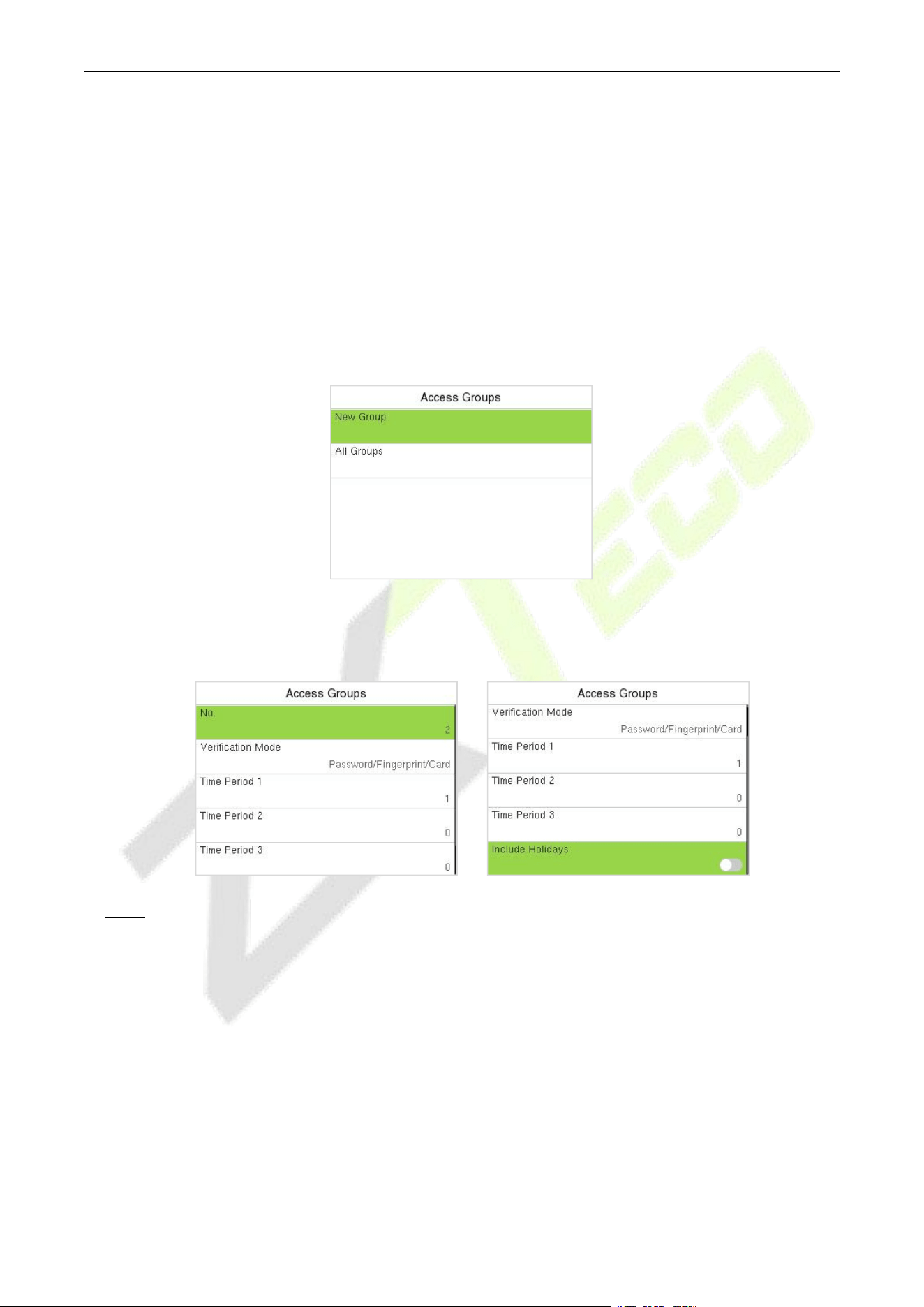
F34 User Manual
P a g e | 73 Copyright © 2026 ZKTECO CO., LTD. All rights reserved.
14.4 Access Groups (T&A PUSH)
Grouping is to manage users in groups, only for time attendance terminal.
The default time zone for group members is the group time zone, while users can set their personal
time zone. When the group verification mode and the user verification mode overlap, the user
verification mode takes priority. Each group can set a maximum of 3 time zones; as long as one of them
is valid, the group can be successfully verified. The newly enrolled user is assigned to Access Group 1 by
default, but can be assigned to another access group.
Select Access Groups on the Access Control interface.
Add a New Holiday:
Select New Group on the Access Group interface.
Note:
1. The system has a default access group numbered 1, which cannot be deleted but can be modified.
2. A number cannot be modified again after being set.
3. When the holiday is set to be valid, the personnel in a group can open the door only when group
time period overlaps with the holiday time period.
4. When the holiday is set to be invalid, the access control time of the personnel in this group is not
affected by holidays.
Edit Group:
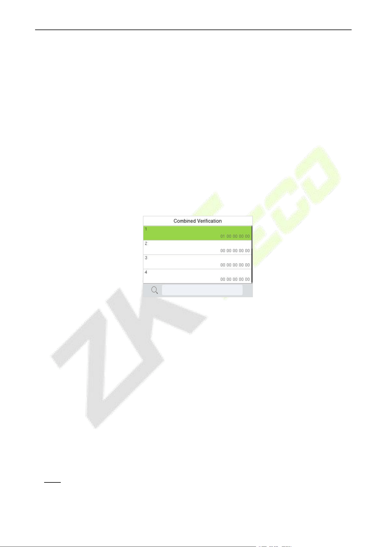
F34 User Manual
P a g e | 74 Copyright © 2026 ZKTECO CO., LTD. All rights reserved.
On the All Group interface, tap to select the access group item to be modified. Select Edit to modify
group parameters.
Delete a Group:
On the All Group interface, select an access group item to be deleted and select Delete. Press M/OK to
confirm the deletion. After deletion, this group does not display on the All Group interface.
14.5 Combined Verification (PUSH Protocol)
Access groups are arranged into different door-unlocking combinations to achieve multiple
verifications and strengthen security.
In a door-unlocking combination, the range of the combined number N is 0 ≤ N ≤ 5 and the number of
members N may all belong to one access group or may belong to five different access groups.
Select Combined Verification on the Access Control interface to configure the combined verification
setting.
On the combined verification interface, select the Door-unlock combination to be set, and press the up
and down arrows to input the combination number, and then press M/OK.
For Example:
If the Door-unlock combination 1 is set as (01 03 05 06 08). It indicates that the unlock
combination 1 consists of 5 people and all the 5 individuals are from 5 groups, namely, AC Group 1,
AC Group 3, AC Group 5, AC Group 6, and AC Group 8, respectively.
If the Door-unlock combination 2 is set as (02 02 04 04 07). It indicates that the unlock
combination 2 consists of 5 people; the first two are from AC Group 2, the next two are from AC
Group 4, and the last person is from AC Group 7.
If the Door-unlock combination 3 is set as (09 09 09 09 09). It indicates that there are 5 people in
this combination; all of which are from AC Group 9.
If the Door-unlock combination 4 is set as (03 05 08 00 00). It indicates that the unlock
combination 4 consists of only three people. The first person is from AC Group 3, the second
person is from AC Group 5, and the third person is from AC Group 8.
Note: To delete the door-unlock combination, set all Door-unlock combinations to 0.
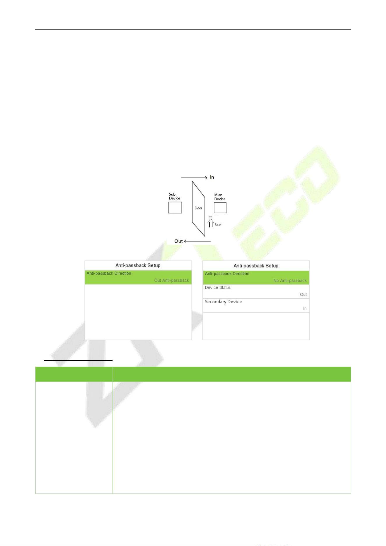
F34 User Manual
P a g e | 75 Copyright © 2026 ZKTECO CO., LTD. All rights reserved.
14.6 Anti-passback Setup (PUSH Protocol)
A user may be followed by some person(s) to enter the door without verification, resulting in a security
breach. So, to avoid such situations, the Anti-Passback option was developed. Once it is enabled, the
check-in and check-out record must occur alternatively to open the door to represent a consistent
pattern.
This function requires two devices to work together:
One device is installed on the indoor side of the door (main device), and the other one is installed on
the outdoor side of the door (the sub device). The two devices communicate via the Wiegand signal.
The Wiegand format and Output type (User ID/Card Number) adopted by the main device and sub
device must be consistent.
Select Anti-passback Setup on the Access Control interface.
A&C PUSH T&A PUSH
Function Description:
Function Name
Description
Anti-passback
Direction
No Anti-passback: The Anti-Passback function is disabled, which means
successful verification through either the main device or sub device can
unlock the door. The attendance state is not saved in this option.
Out Anti-passback: The user can check-out only if the last record is a check-
in record otherwise an alarm is raised. However, the user can check-in freely.
In Anti-Passback: The user can check-in again only if the last record is a
check-out record otherwise an alarm is raised. However, the user can check-
out freely.
In/Out Anti-passback: In this case, a user can check-in only if the last record
is a check-out or the user can check-out only if the last record is a check-in
otherwise the alarm is triggered.
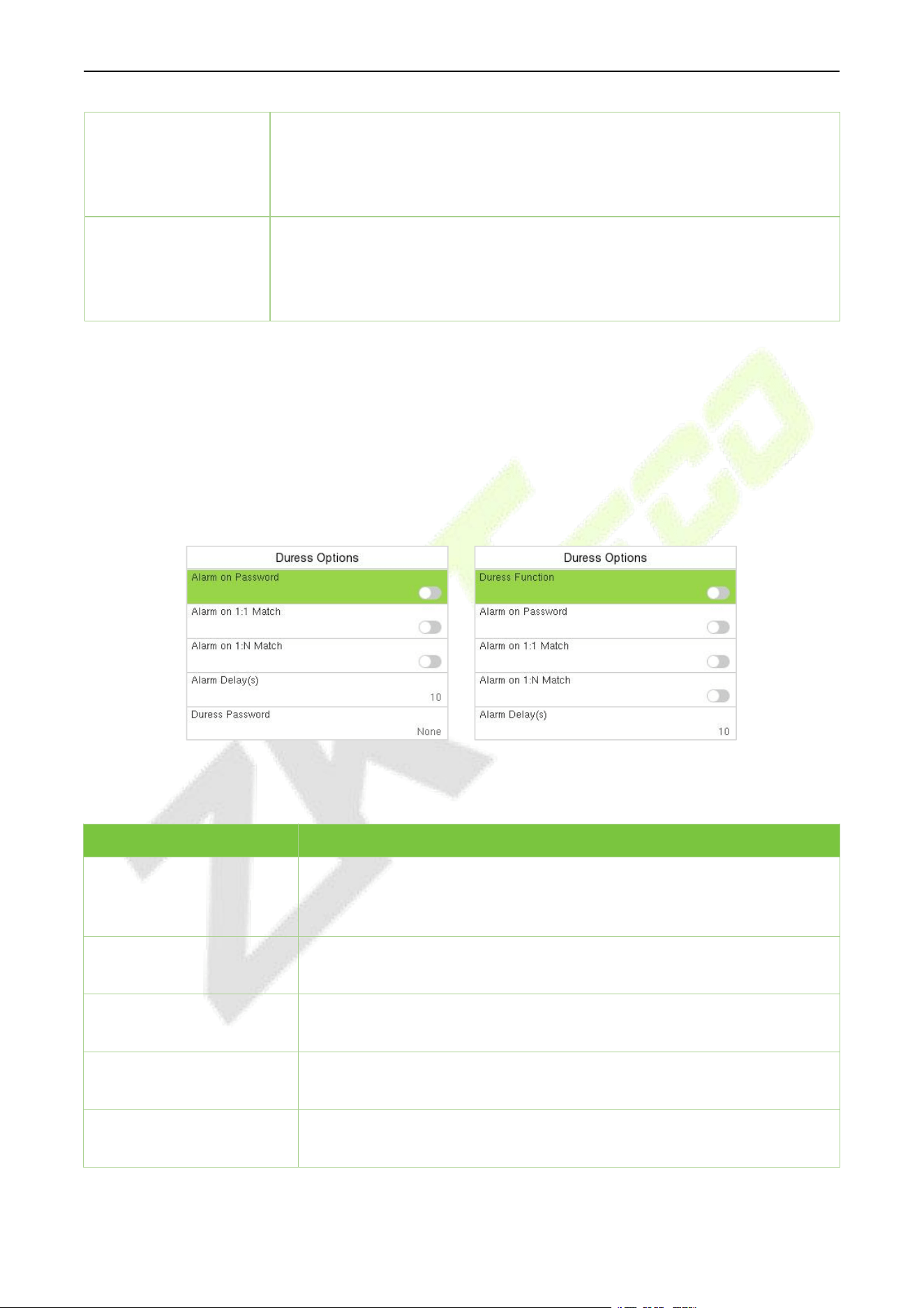
F34 User Manual
P a g e | 76 Copyright © 2026 ZKTECO CO., LTD. All rights reserved.
Device Status
Set the state of the device as Out or In.
Out: A record of verification on the device is a check-out record.
In: A record of verification on the device is a check-in record.
Secondary Device
Set the state of the secondary as Out or In.
Out: A record of verification on the secondary device is a check-out record.
In: A record of verification on the secondary device is a check-in record.
14.7 Duress Options Settings (PUSH Protocol)
Once a user activates the duress verification function with a specific authentication method(s), and
when he/she is under coercion and authenticates using duress verification, the device unlocks the door
as usual. At the same time, a signal is sent to activate the alarm as well.
On the Access Control interface, select Duress Options to configure the duress settings.
A&C PUSH T&A PUSH
A&C PUSH:
Function Name
Description
Alarm on Password
After enabled, when a user uses the password verification method, an
external alarm signal will be generated, otherwise there will be no alarm
signal.
Alarm on 1:1 Match
After enabled, when a user uses the 1:1 verification method, an external
alarm signal will be generated, otherwise there will be no alarm signal.
Alarm on 1:N Match
After enabled, when a user uses the 1:N verification method, an external
alarm signal will be generated, otherwise there will be no alarm signal.
Alarm Delay (s)
Alarm signal will not be transmitted until the alarm delay time is elapsed.
The value ranges from 1 to 999 seconds.
Duress Password
Set the 6-digit duress password. When the user enters this duress
password for verification, an external alarm signal will be generated.
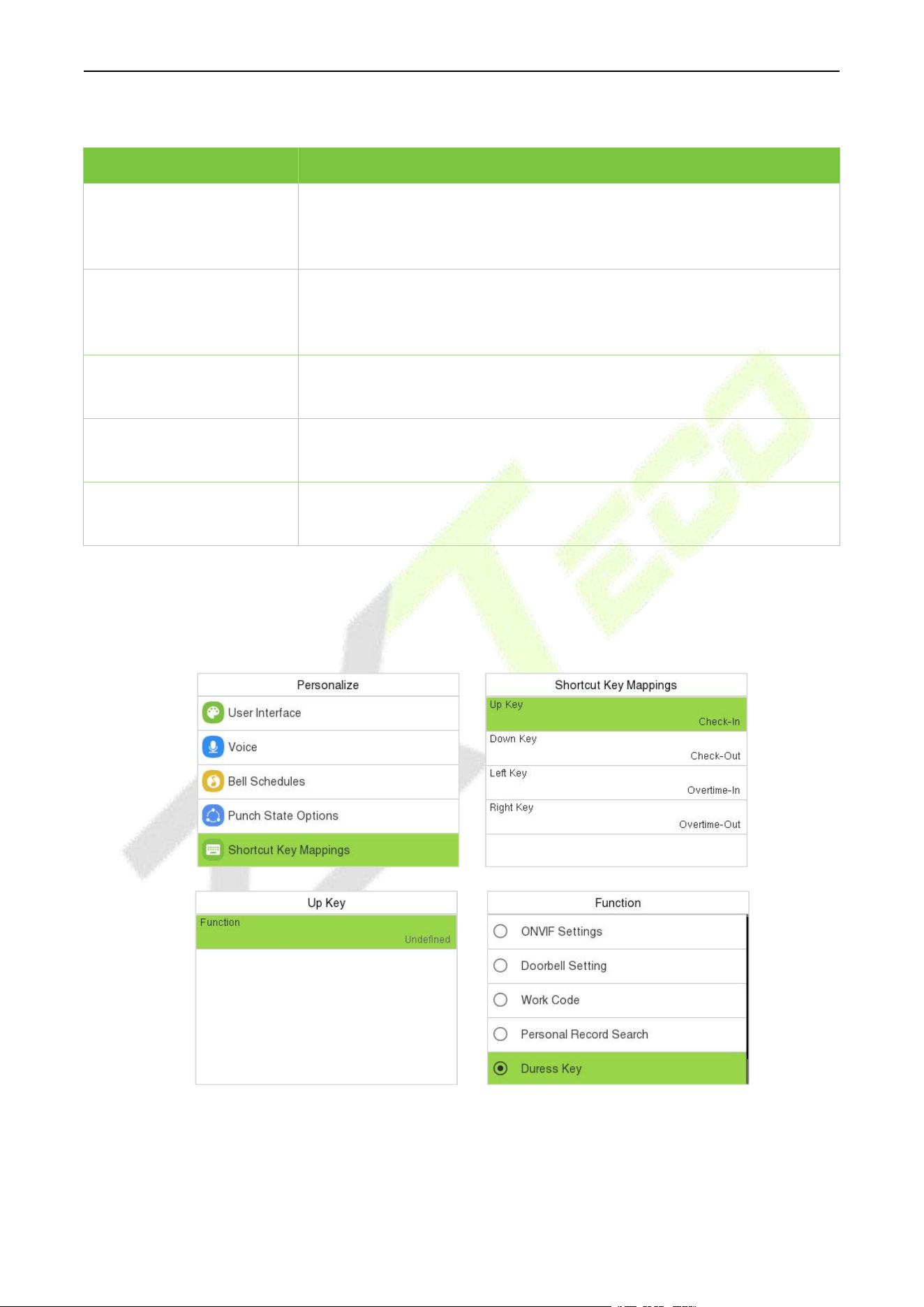
F34 User Manual
P a g e | 77 Copyright © 2026 ZKTECO CO., LTD. All rights reserved.
T&A PUSH:
Function Name
Description
Duress Function
After enabled, Duress Key can be set in the Shortcut Key Mappings. After
pressing the "Duress Key", then (within 10 seconds) press any registered
fingerprint to generate an external alarm upon successful verification.
Alarm on Password
After enabled, when a user uses the password verification method, an
external alarm signal will be generated, otherwise there will be no alarm
signal.
Alarm on 1:1 Match
After enabled, when a user uses the 1:1 verification method, an external
alarm signal will be generated, otherwise there will be no alarm signal.
Alarm on 1:N Match
After enabled, when a user uses the 1:N verification method, an external
alarm signal will be generated, otherwise there will be no alarm signal.
Alarm Delay (s)
Alarm signal will not be transmitted until the alarm delay time is elapsed.
The value ranges from 1 to 999 seconds.
Duress Key Settings (Such as set Up Key] as Duress Key)
After enabled the Duress Function, enter Personalize > Short Shortcut Key Mappings. Select the Up
Key > Function > select the “Duress Key” option.
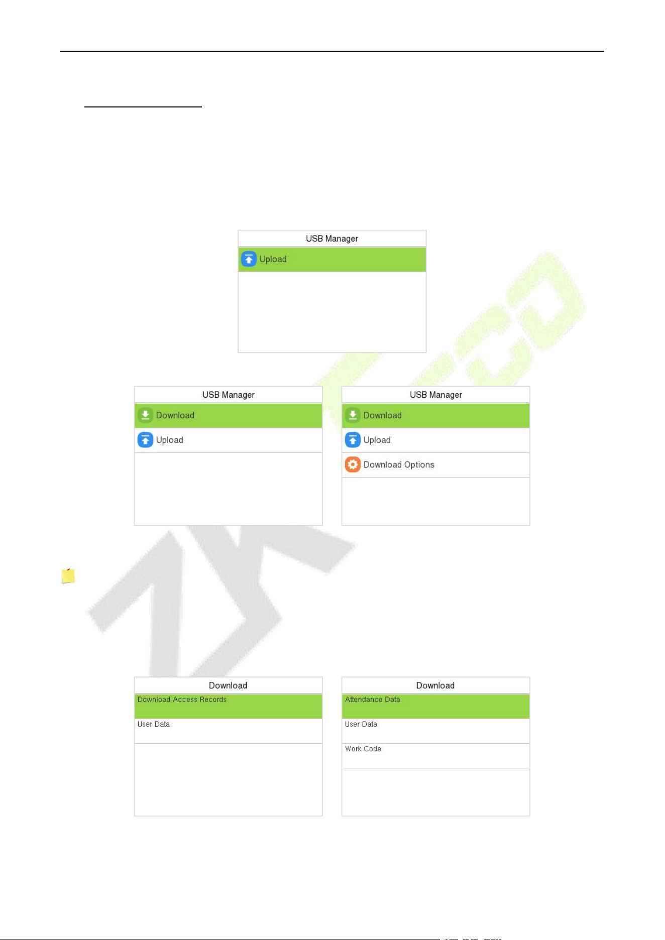
F34 User Manual
P a g e | 78 Copyright © 2026 ZKTECO CO., LTD. All rights reserved.
15 USB Manager
You can import user information, access data and other data from a USB drive to computer or other
devices.
Before uploading/downloading data from/to the USB disk, insert the USB disk into the USB slot first.
Select USB Manager on the main menu interface.
BEST Protocol
A&C PUSH T&A PUSH
Note: Only FAT32 format is supported when downloading data using USB disk.
15.1 USB Download (PUSH Protocol)
On the USB Manager interface, select Download.
A&C Terminal T&A Terminal
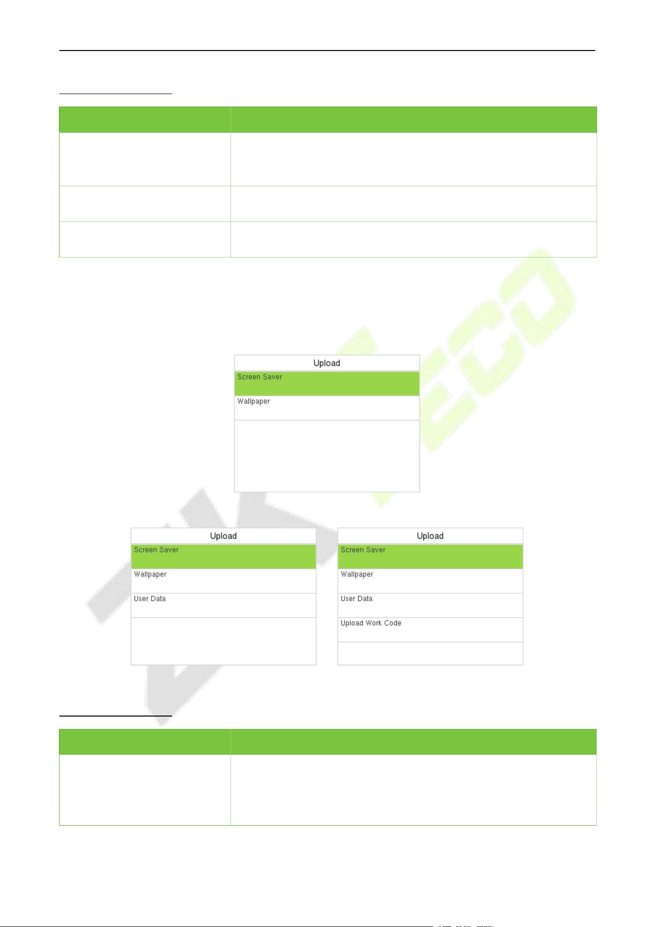
F34 User Manual
P a g e | 79 Copyright © 2026 ZKTECO CO., LTD. All rights reserved.
Function Description
Function Name
Description
Download Access
Records/Attendance Data
To download access record/attendance data in specified time period
into USB disk.
User Data
To download all user information from the device into USB disk.
Work Code
To download all work code from the device into USB disk.
15.2 USB Upload
On the USB Manager interface, select Upload.
BEST Protocol
A&C PUSH T&A PUSH
Function Description
Function Name
Description
Screen Saver
To upload all screen savers from USB disk into the device. You can
choose Upload selected photo or Upload all photos. The images will
be displayed on the device’s main interface after upload.
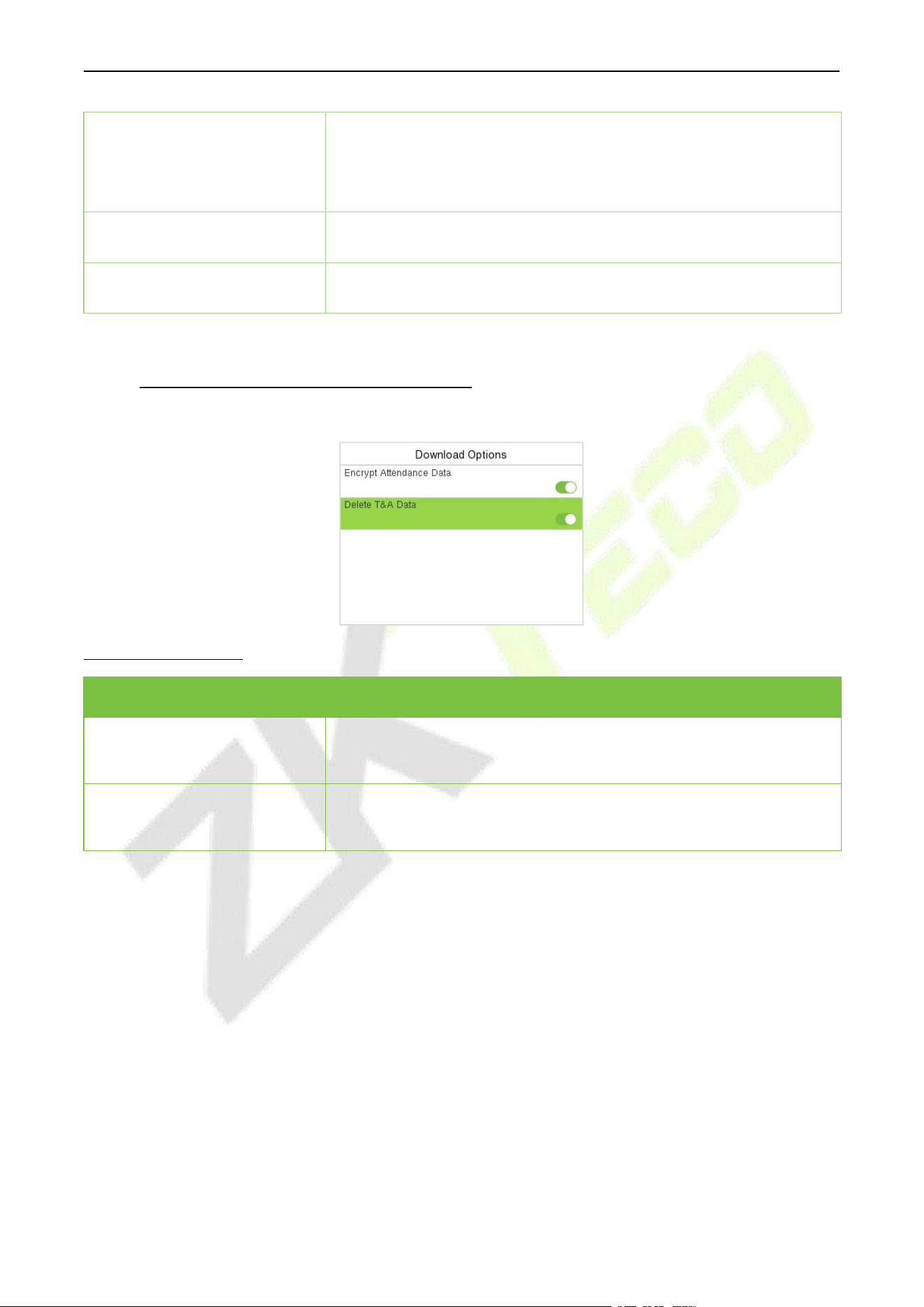
F34 User Manual
P a g e | 80 Copyright © 2026 ZKTECO CO., LTD. All rights reserved.
Wallpaper
To upload all wallpapers from USB disk into the device. You can
choose Upload selected photo or Upload all photos. The images will
be displayed on the screen after upload.
User Data
To upload all the user information from USB disk into the device.
Upload Work Code
To upload all work code from USB disk into the device.
15.3 Download Options (T&A PUSH)
On the USB Manager interface, select Download Options.
Function Description
Function Name
Description
Encrypt Attendance Date
The attendance data is encrypted during the uploading and
downloading.
Delete T&A Data
After successful downloading, the attendance data on the device is
deleted.
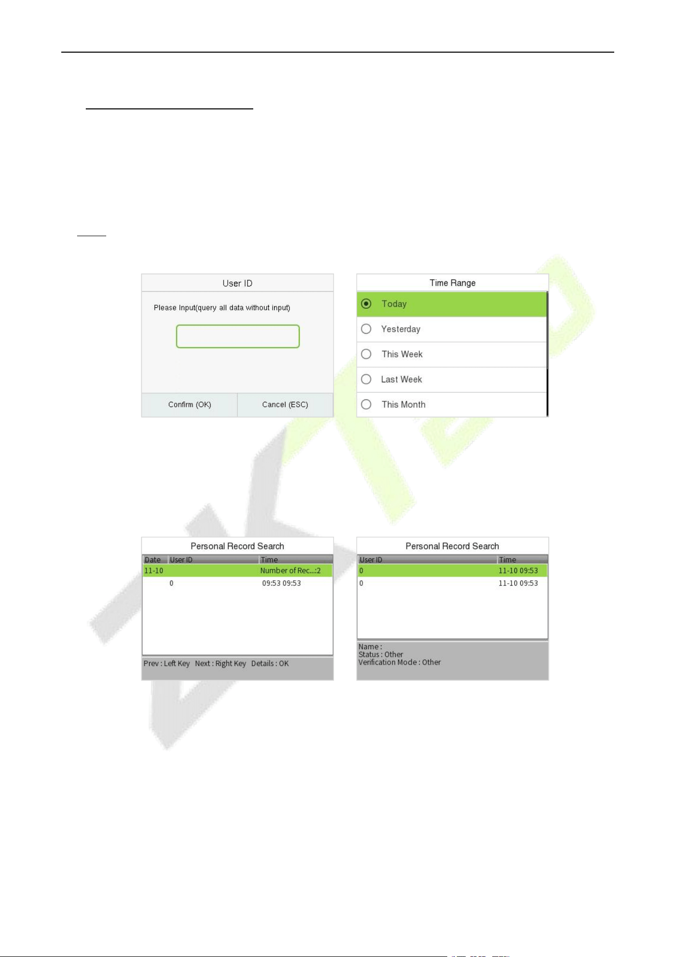
F34 User Manual
P a g e | 81 Copyright © 2026 ZKTECO CO., LTD. All rights reserved.
16 Attendance Search
Once the identity of a user is verified, the access record/attendance data is saved in the device. This
function enables users to check their event logs.
When the device is on the initial interface, press [M/OK] button and enter Attendance Search to
search for the required event Logs.
Note: The event logs include not only successful verification records, but also the failed verification
records.
1. Enter the user ID to be searched
and press M/OK. If you want to
search for records of all users,
press M/OK without entering
any user ID.
2. Select the time range in which
the records need to be
searched.
3. Once the record search completes.
Tap the record highlighted in
green to view its details.
4. The figure shows the details of
the selected record.
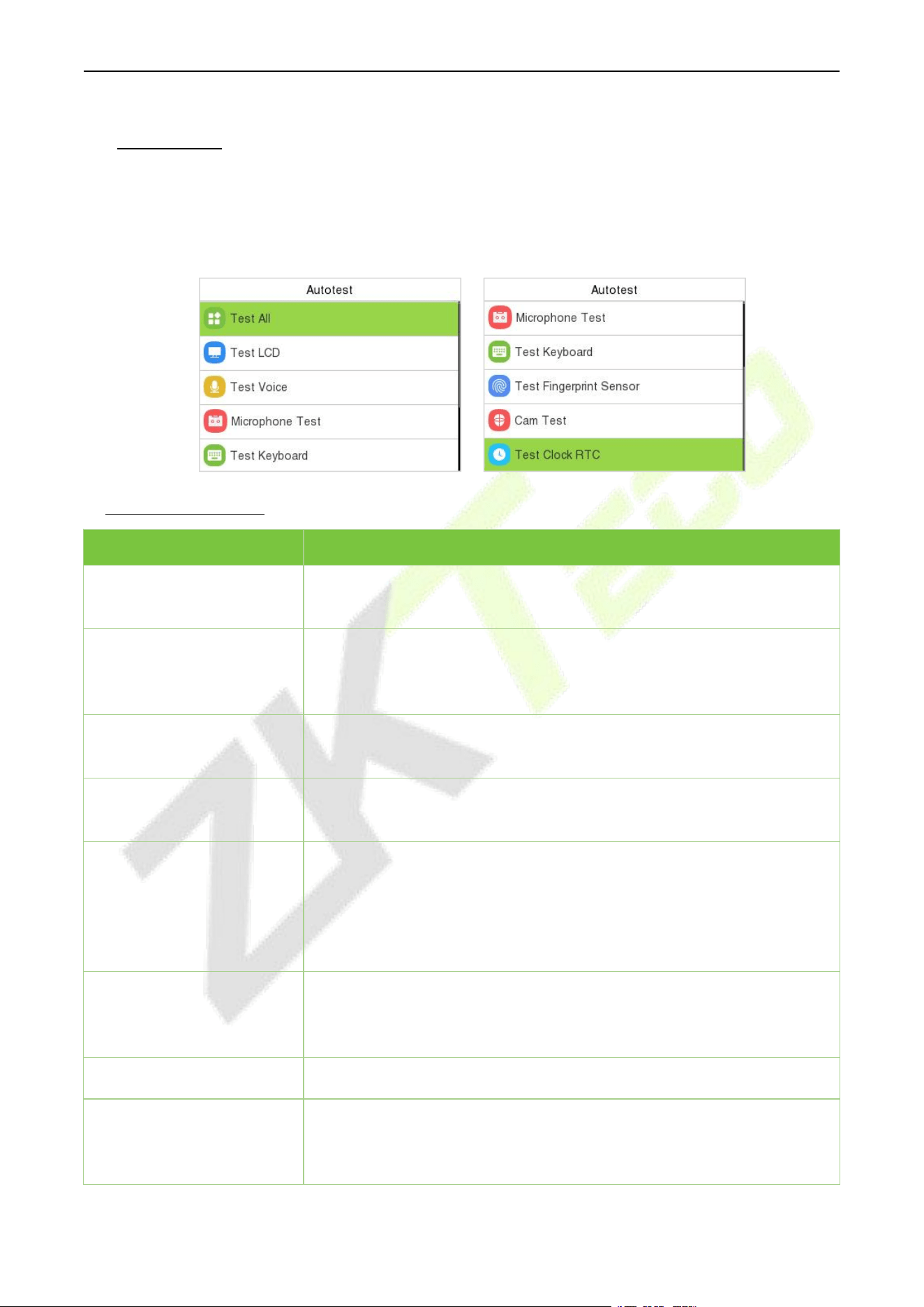
F34 User Manual
P a g e | 82 Copyright © 2026 ZKTECO CO., LTD. All rights reserved.
17 Autotest
When the device is on the initial interface, press [M/OK] button and enter Autotest, it enables the
system to automatically test whether the functions of various modules are working normally, including
the LCD, Voice, Keyboard, Fingerprint and Real-Time Clock (RTC).
Function Description
Function Name
Description
Test All
To automatically test whether the LCD, Voice, Fingerprint and Real-Time
Clock (RTC) are normal.
Test LCD
To automatically test the display effect of LCD screen by displaying full-
color, pure white, and pure black to check whether the screen displays
colors normally.
Test Voice
To automatically test whether the audio files stored in the device are
complete and the voice quality is good.
Microphone test
To test if the microphone is working properly by speaking into the
microphone.
Test Keyboard
The terminal tests whether every key on the keyboard works normally.
Press any key on the Test Keyboard interface to check whether the
pressed key matches the key displayed on the screen. The keys are
displayed as dark grey before and turn green after pressed. Press ESC to
exit the test.
Test Fingerprint Sensor
To test the fingerprint sensor by pressing a finger on the scanner to
check if the acquired fingerprint image is clear. When you are pressing a
finger on the scanner, the fingerprint image will display on the screen.
Cam Test
To test if the camera functions properly.
Test Clock RTC
To test the RTC. The device tests whether the clock works normally and
accurately with a stopwatch. Press M/OK to start counting and press it
again to stop counting.
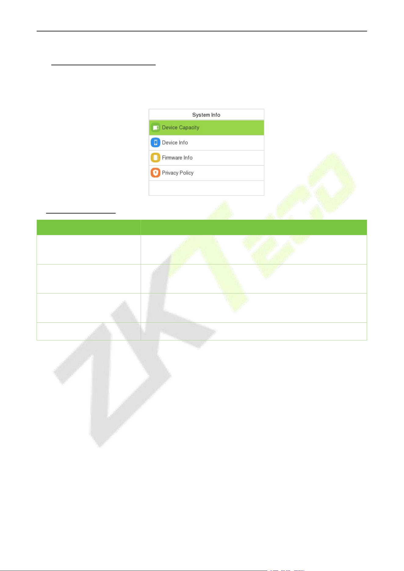
F34 User Manual
P a g e | 83 Copyright © 2026 ZKTECO CO., LTD. All rights reserved.
18 System Information
When the device is on the initial interface, press [M/OK] button and enter System Info to view the
storage status, version information of the device, firmware information and privacy policy.
Function Description
Function Name
Description
Device Capacity
Displays the current device's user storage, fingerprint, card and
password storage, administrators and records.
Device Info
Displays the device's name, serial number, MAC address, Fingerprint
algorithm, Platform information, MCU Version and Manufacturer.
Firmware Info
Displays the firmware version and other version information of the
device.
Privacy Policy
Display the device's privacy policy.
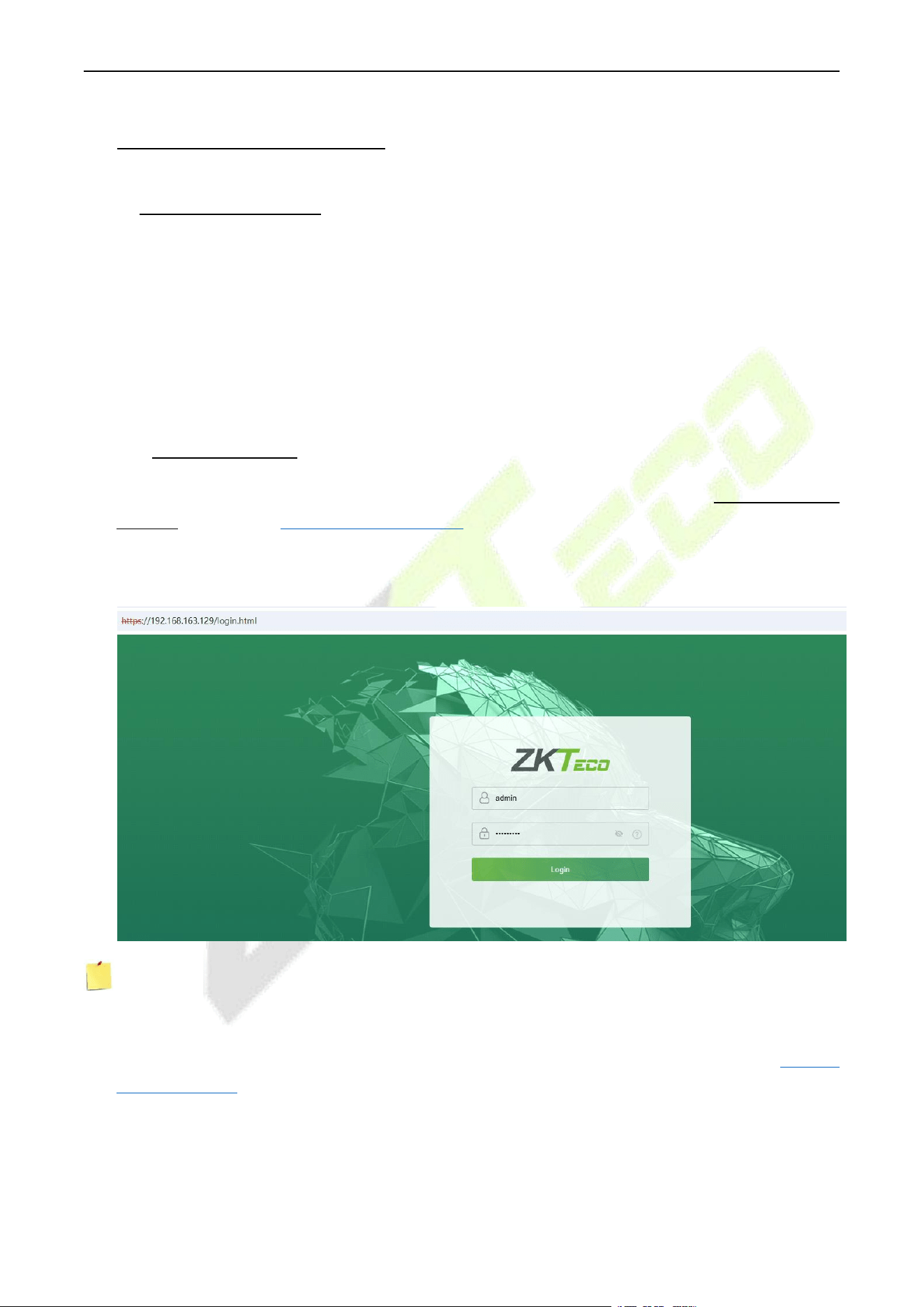
F34 User Manual
P a g e | 84 Copyright © 2026 ZKTECO CO., LTD. All rights reserved.
19 Connect to Webserver
19.1 Login Webserver
There are two modes to access the device’s webserver: Standard mode and AP mode.
Standard Mode allows users to access the device's Webserver via the Internet or LAN, enabling
communication and data transfer between the device and software over the network.
In AP Mode, the device can emit an AP hotspot, allowing users to connect to the WiFi hotspot via mobile
devices (smartphones, tablets, etc.) and then access the device's built-in webserver directly through a
browser for remote management.
19.1.1 Standard Mode
1. Open a browser to enter the address to log in to the WebServer, the address is https:// Serial IP
Address. For example: https://192.168.163.129.
2. Enter the WebServer account and password, the default account is: admin, password: admin@123.
Note:
1. After logging in for the first time, it is required that the users change their original password.
2. In order to retrieve the password easily, please register a super admin first, please refer to 6.1 New
User Registration.
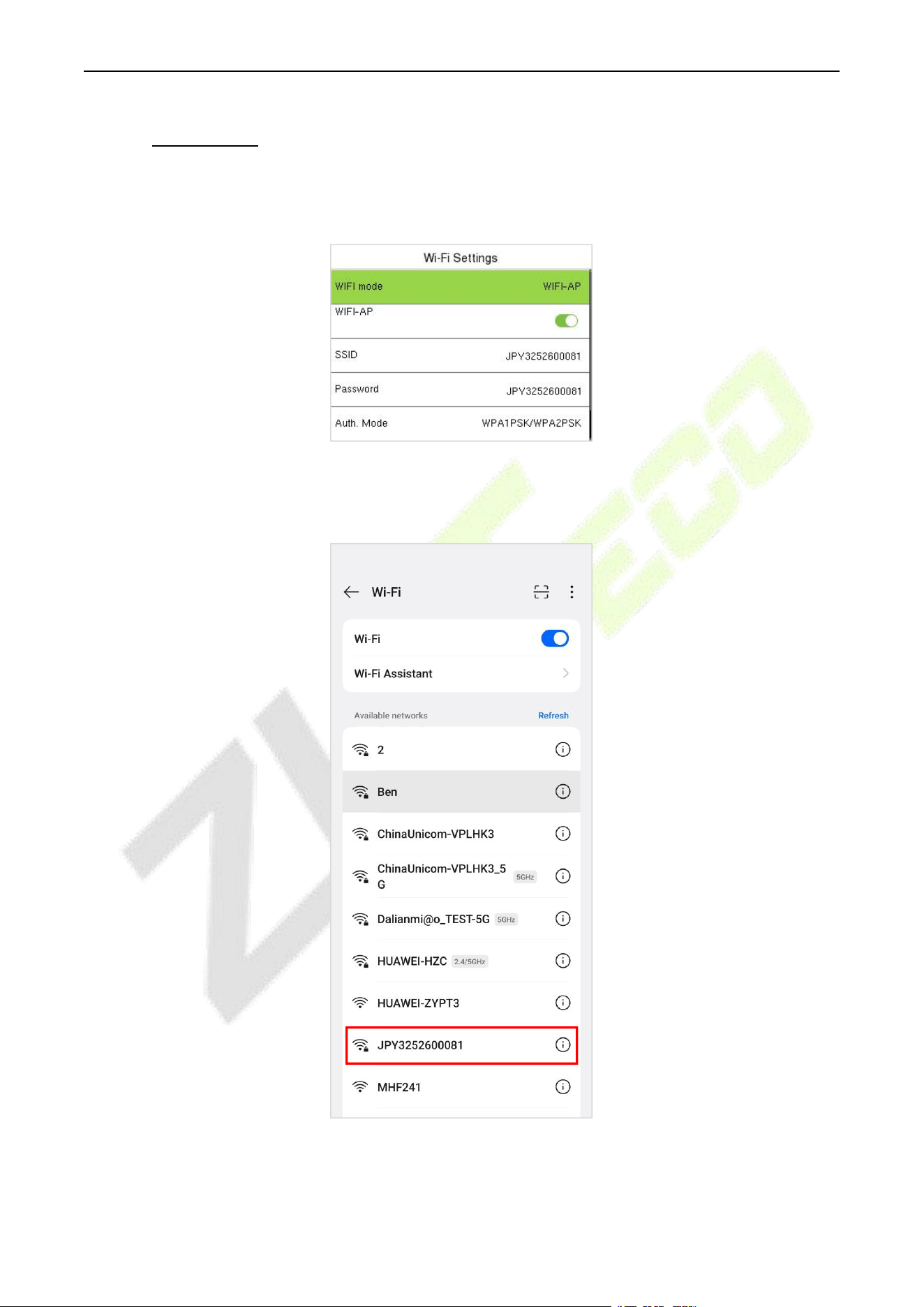
F34 User Manual
P a g e | 85 Copyright © 2026 ZKTECO CO., LTD. All rights reserved.
19.1.2 AP Mode★
1. Enter COMM. > Wi-Fi Settings, change the WiFi mode as WIFI-AP and enable it. The default SSID and
password are: [Device Serial Number] / [Device Serial Number].
2. Turn on the Wi-Fi switch of your smartphone. Select the Wi-Fi that named after the device serial
number from the available list and input the password (default: same as device serial number) to
connect it.
3. After the Wi-Fi is connected successfully, it will jump to the webserver login page. Enter the
WebServer account and password, the default account is: admin, password: admin@123.
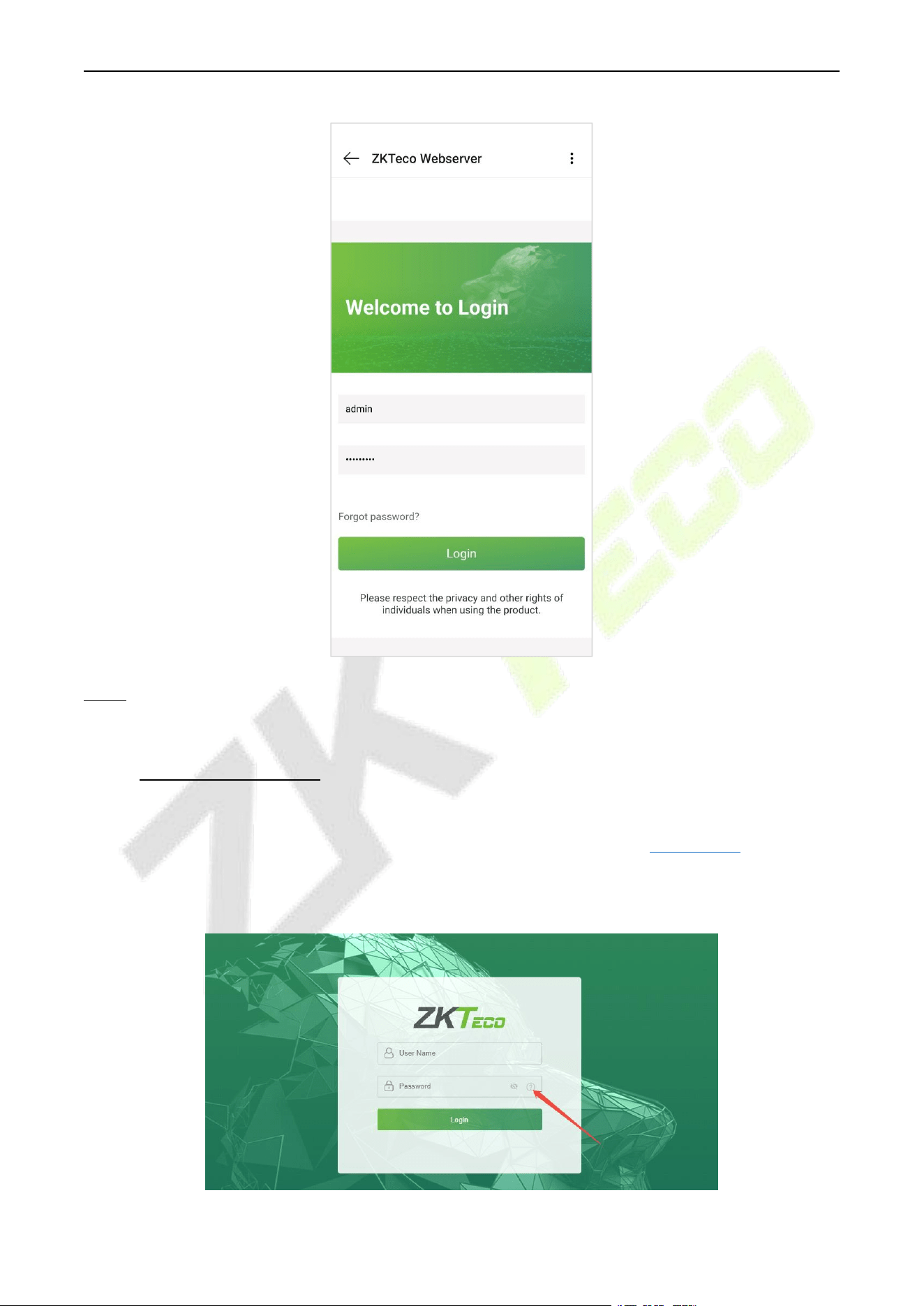
F34 User Manual
P a g e | 86 Copyright © 2026 ZKTECO CO., LTD. All rights reserved.
Note: The operation of Webserver on the PC and smartphone is generally the same. The following text
takes PC as an example to illustrate.
19.2 Forgot Password
Method 1 (When there is a super admin):
If you forgot the password of WebServer, you could reset it by the registered super admin. The detailed
steps are as follows:
1. Click the icon on the login interface.
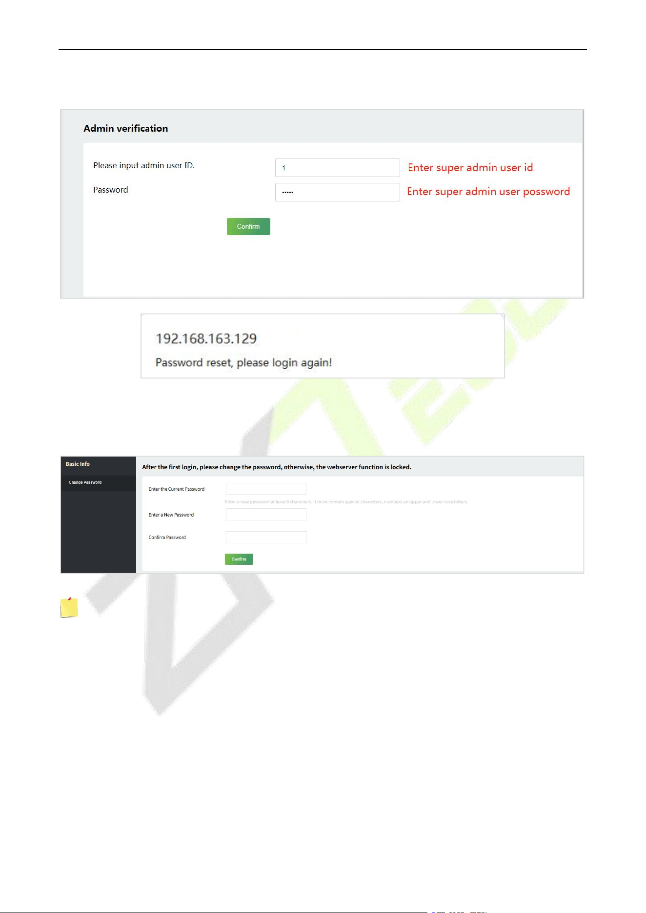
F34 User Manual
P a g e | 87 Copyright © 2026 ZKTECO CO., LTD. All rights reserved.
2. On the pop-up page, enter the relevant information of the super admin user as prompted.
3. After a successful reset, enter the default account and password (account: admin, password: admin@123)
on the login interface to log in.
4. For security reasons, it is required to change your password after successfully logging in.
Note: The super admin must exist.
Method 2 (When there is not a super admin):
If the network of the device is normal and ZKBio Zlink / ZKBio CVAccess / ZKBio Time / ZKBio Time Cloud
has been connected, you can reset the password by sending the super admin account and password from
the server.
1. Click Personnel > Person > New on the ZKBio Zlink / ZKBio CVAccess / ZKBio Time / ZKBio Time
Cloud Server; register the super admin information and set the super admin role on the new interface
as required. (Here take ZKBio CVAccess interface as an example)
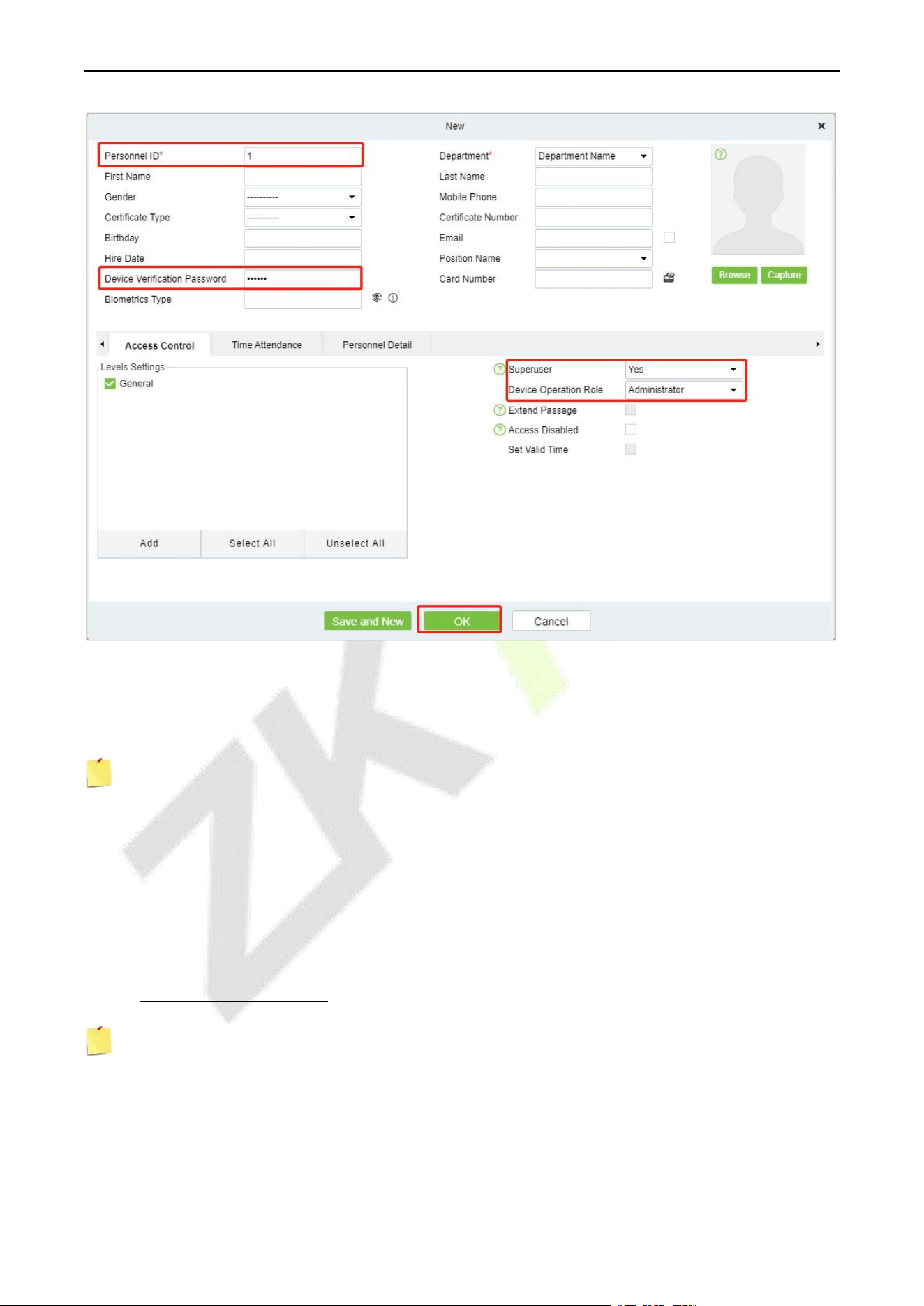
F34 User Manual
P a g e | 88 Copyright © 2026 ZKTECO CO., LTD. All rights reserved.
2. After registering the information of the super admin, click OK.
3. Click Access > Device > Control > Synchronize All Data to Devices to synchronize all the data to
the device including the new users.
Note: For other specific operations, please refer the relevant software User Manual.
4. After the data synchronization is successful, you can reset the password with the newly registered
super admin. The operation steps are the same as method 1.
Method 3:
If the device has not registered a super admin and cannot connect to the server, please contact our after-
sales technicians to help retrieve the password.
19.3 Basic Information
Note: The Webserver interface display may vary depending on the device type (BEST Protocol/A&C
PUSH/T&A PUSH). The following text takes A&C PUSH as an example to illustrate.
Click Basic Info on the WebServer. In this interface, you can view the basic information and network status
of the current device.
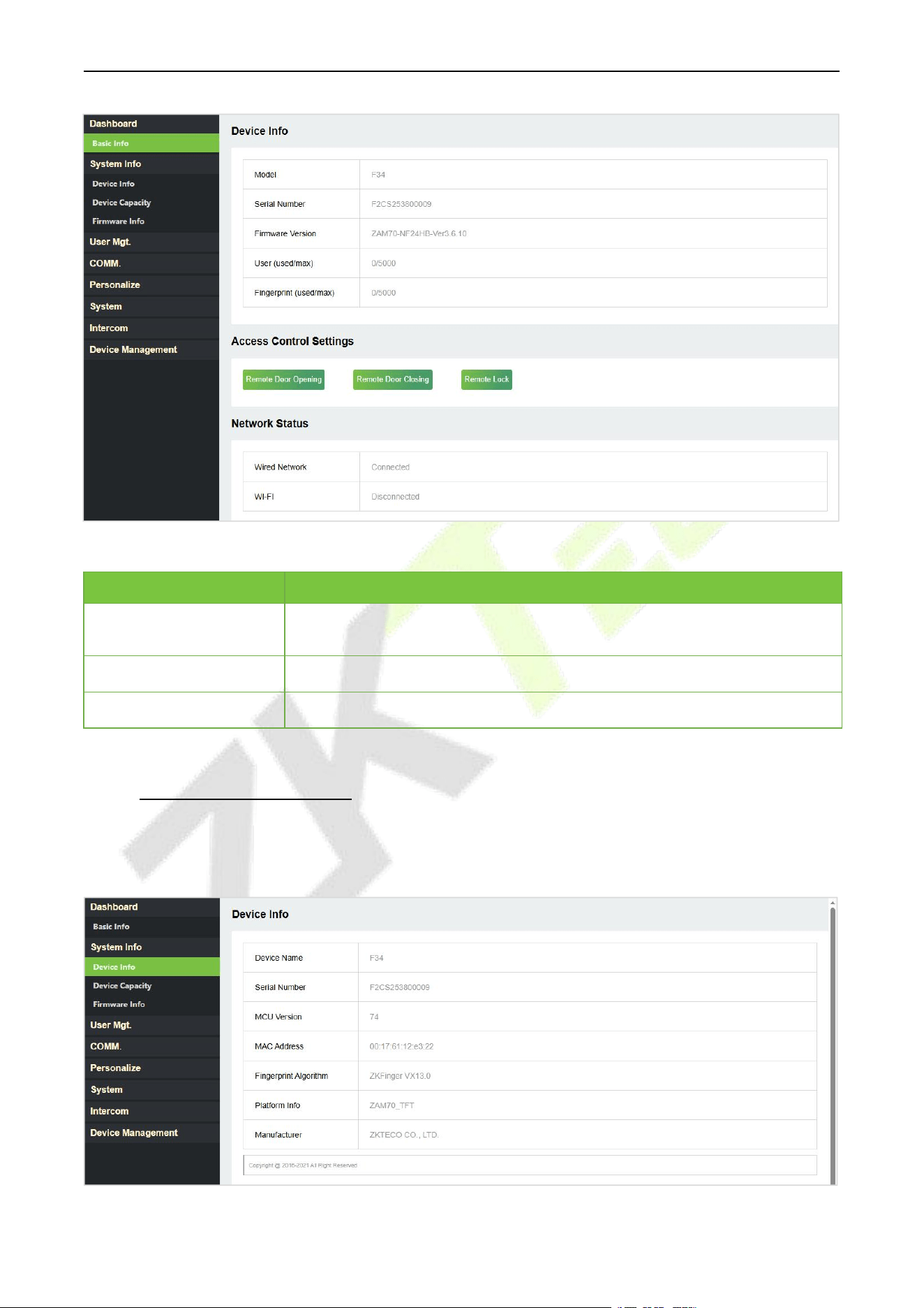
F34 User Manual
P a g e | 89 Copyright © 2026 ZKTECO CO., LTD. All rights reserved.
Access Control Settings:
Function Name
Description
Remote Door Opening
Click it to open the door remotely. If the operation is successful, the device
will prompt “Door opened”.
Remote Door Closing
Click it to close the door remotely.
Remote Lock/unlock
Click here to lock or unlock remotely.
19.4 System Information
Click DeviceInfo/Device Capacity/FirmwareInfo onthe WebServer.
In the interface, you can view the data capacity, device and firmware information of the current device.
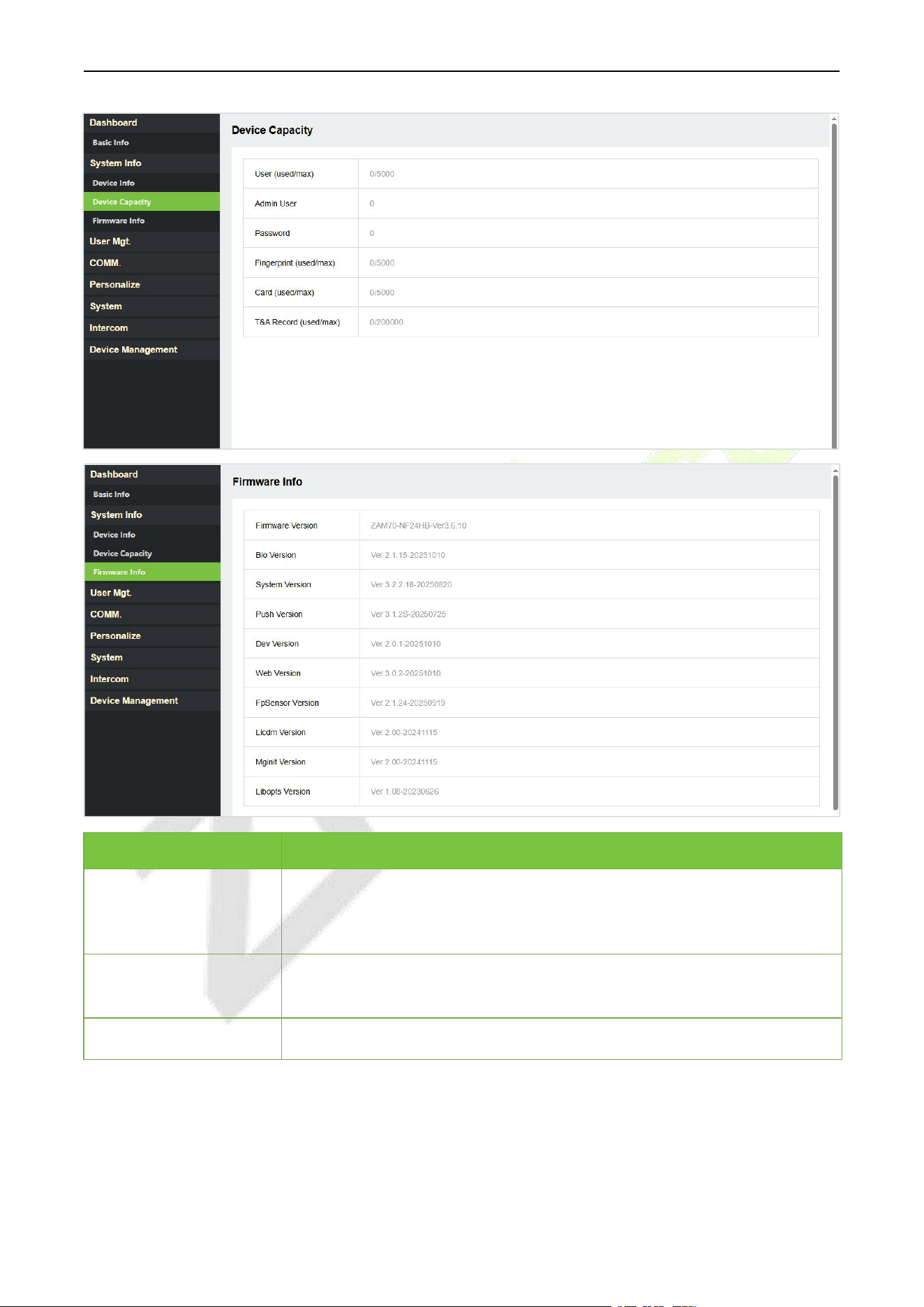
F34 User Manual
P a g e | 90 Copyright © 2026 ZKTECO CO., LTD. All rights reserved.
Function Name
Description
Device Info
Displays the device's name, serial number, MCU version, MAC address,
fingerprint algorithm version information, platform and manufacturer
information.
Device Capacity
Displays the current device's user storage, password, fingerprint, card
storage, administrators, and event logs.
Firmware Information
Displays the firmware version and other version information of the device.
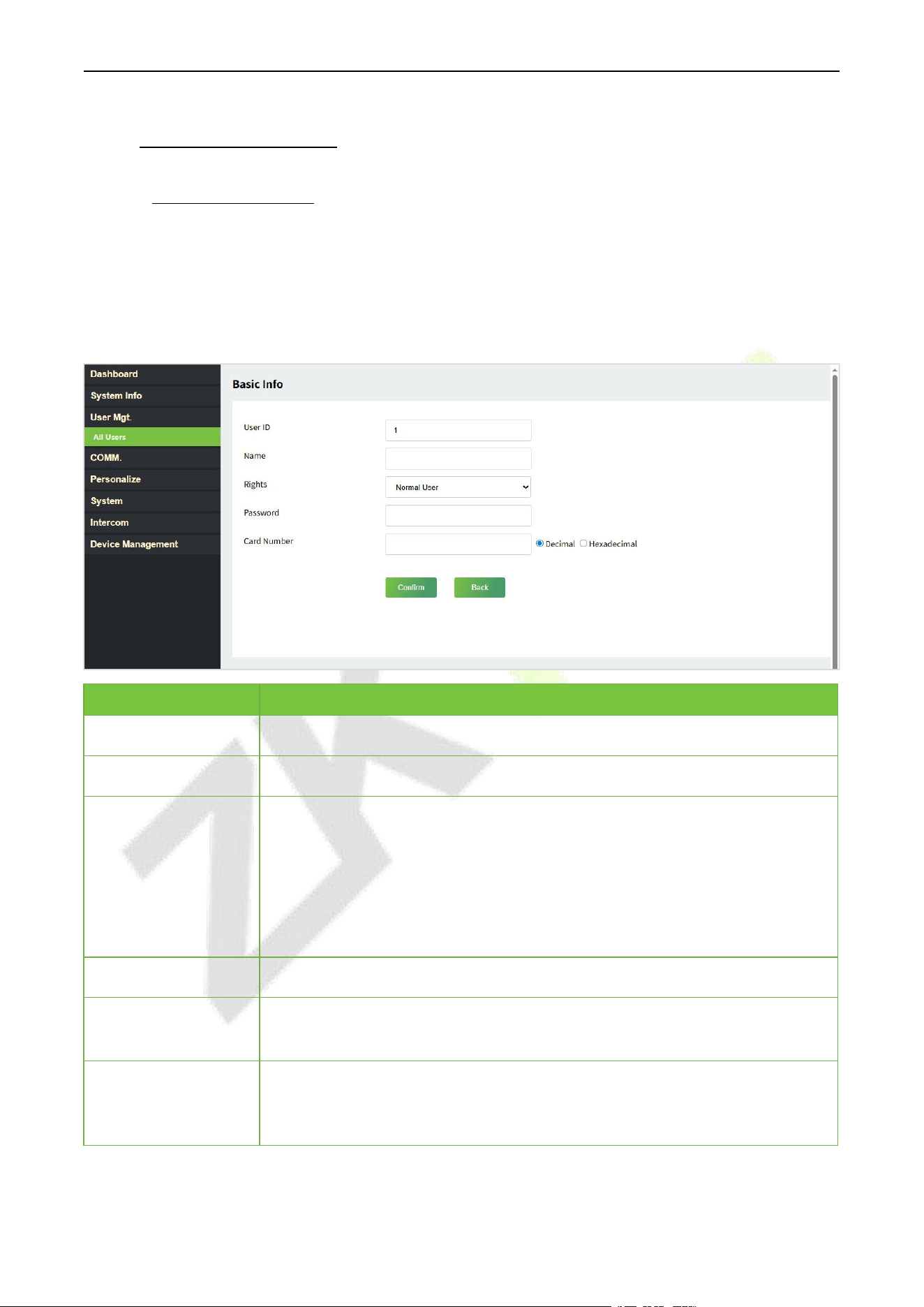
F34 User Manual
P a g e | 91 Copyright © 2026 ZKTECO CO., LTD. All rights reserved.
19.5 User Management
19.5.1 User Registration
Basic Information
Click All Users > New User on the WebServer.
In this interface, you can register the User ID, Name, Rights, Password, Card Number and Access Control
Role of the new user, click Confirm to save.
Function Name
Description
User ID
The user ID may contain 1 to 14 characters by default.
Name
A name can be up to 63 characters.
Rights
Set the role for the user as either Normal User or Super Admin.
Super Admin: The Super Admin owns all management privileges in the
WebServer.
Normal User: If the Super Admin is already registered in the WebServer,
then the Normal Users will not have the privileges to manage the system
and can only access authentication verifications.
Password
Set the user's registration password.
Card Number
Select the type of the card number and enter it manually, after registering the
user's card number, the user can swipe the card for verification.
Access Control Role
The Access Control Role sets the door access privilege for each user, new users
will be added to Group 1 by default, which can be reassigned to other required
groups. The system supports up to 10 access control groups.
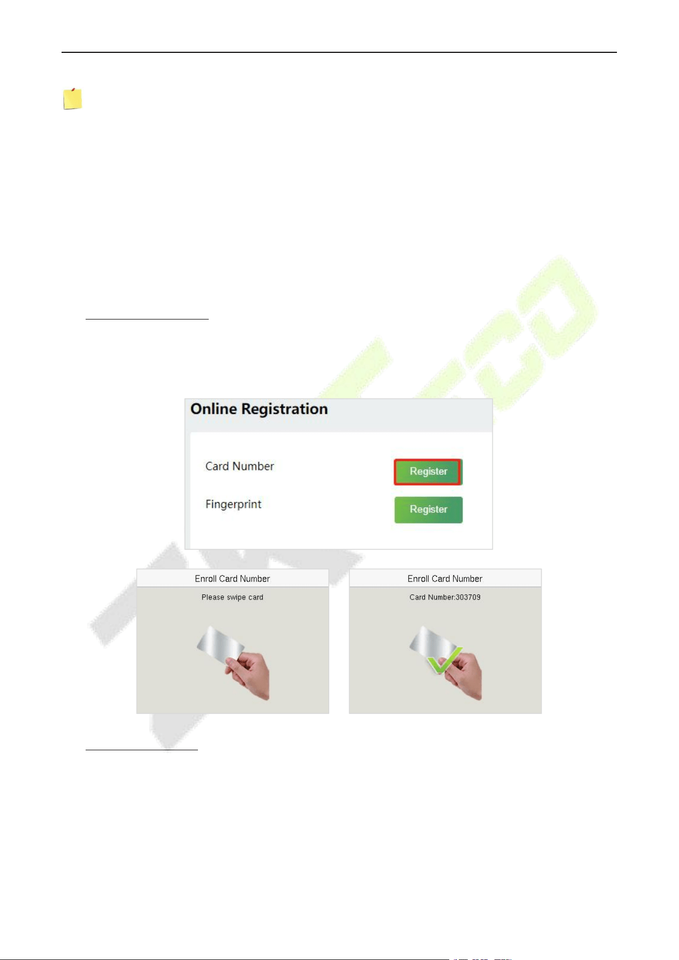
F34 User Manual
P a g e | 92 Copyright © 2026 ZKTECO CO., LTD. All rights reserved.
Note:
1. During the initial registration, you can modify your ID; you cannot be modifying the registered ID
once after the successful registration.
2. If the message "Registration failed!" pops up, you must choose a different User ID because the one
you entered already exists.
Online Registration
In this interface, you can register the User’s Card Number and Fingerprint. The verification mode can only
be registered after the basic information is confirmed.
Register Card Number
In the current interface, behind the card number bar, click Register, and the device will display the card
number registration interface in real time, swipe the card underneath the card reading area. The
registration of the card will be successful.
Register Fingerprint
In the current interface, behind the fingerprint bar, click Register, and the device will display the
fingerprint registration interface in real time, press your finger onto the fingerprint sensor of the device,
and follow the instructions to complete the registration.
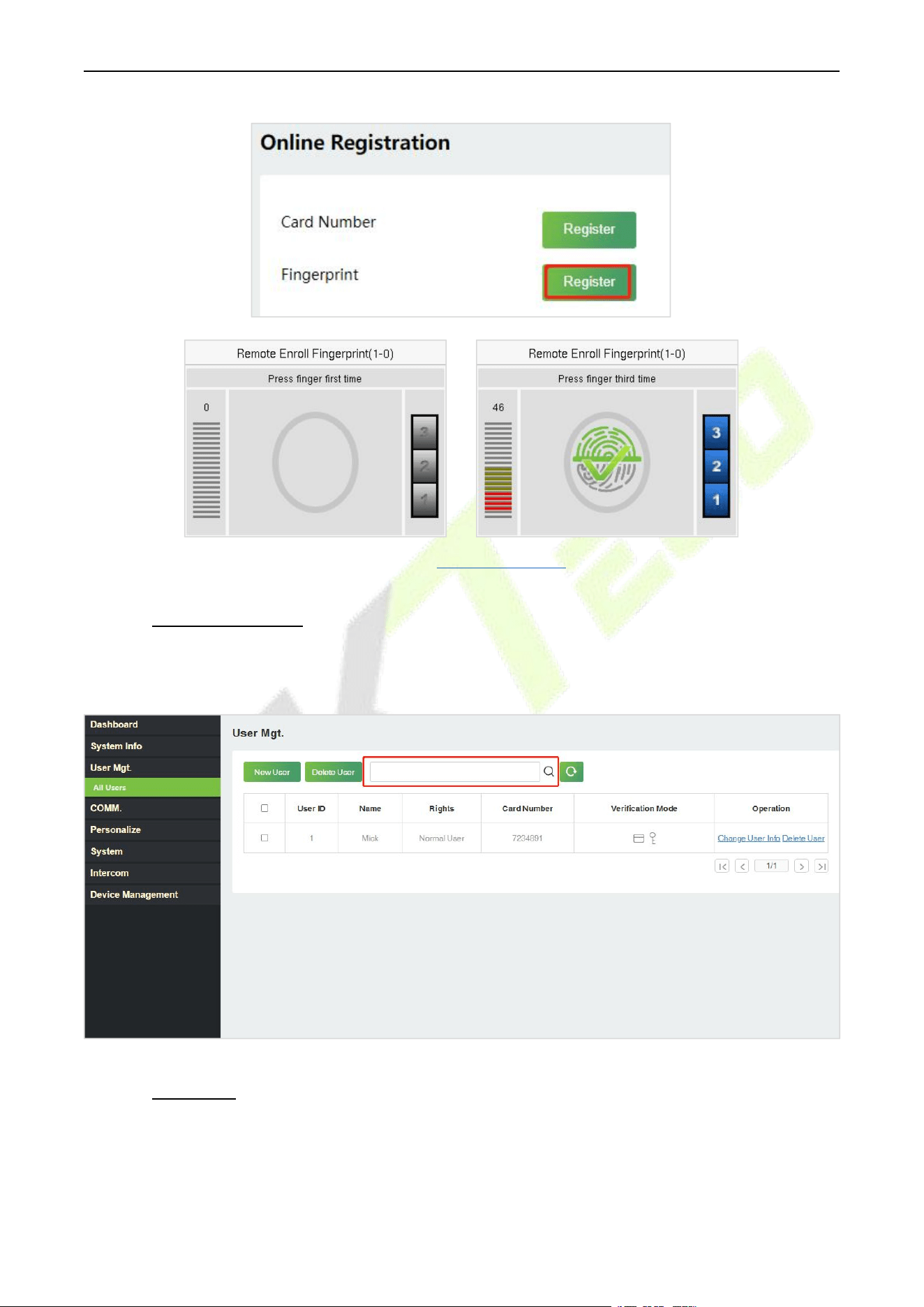
F34 User Manual
P a g e | 93 Copyright © 2026 ZKTECO CO., LTD. All rights reserved.
For fingerprint pressing operation, please refer to Finger Positioning.
19.5.2 Search for Users
Click All Users on the WebServer, click the search bar to enter the required retrieval keyword (where the
keyword may be the user ID or full name) and the system will search for the related user information.
19.5.3 Edit User
On the All Users interface, select the required user from the list and click Change User Info to edit the
user information.
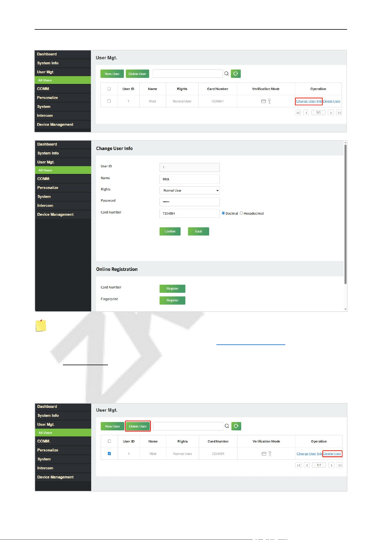
F34 User Manual
P a g e | 94 Copyright © 2026 ZKTECO CO., LTD. All rights reserved.
Note: The process of editing the user information is the same as that of adding a new user, except that
the User ID cannot be modified. The process in detail refers to 18.5.1 User Registration.
19.5.4 Delete User
On the All Users interface, select the required user from the list and click Delete User to delete the user.
Here individual deletion and batch deletion is available.
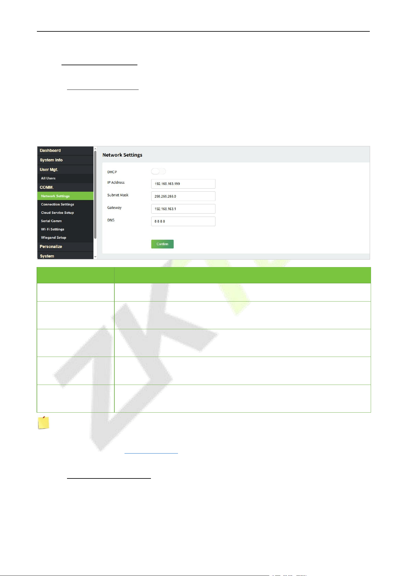
F34 User Manual
P a g e | 95 Copyright © 2026 ZKTECO CO., LTD. All rights reserved.
19.6 Communication
19.6.1 Network Settings
Click NetworkSettings on the WebServer.
Change the IP address of the device as needed, click Confirm to save, and the device will automatically
synchronize the IP information.
Function Name
Description
DHCP
Select whether to obtain the IP Address by automatically.
IP Address
The default IP address is 192.168.1.201. It can be modified according to network
availability.
Subnet Mask
The default Subnet Mask is 255.255.255.0. It can be modified according to
network availability.
Gateway
The Default Gateway address is 0.0.0.0. It can be modified according to network
availability.
DNS
The default DNS address is 0.0.0.0. It can be modified according to network
availability.
Note: After the IP address of the device is changed successfully, you need to log out of the currently
WebServer and log in again to the IP address you just changed to connect to the device. For WebServer
login details, please refer to Login WebServer.
19.6.2 Connection Settings
Click ConnectionSettings on the WebServer.
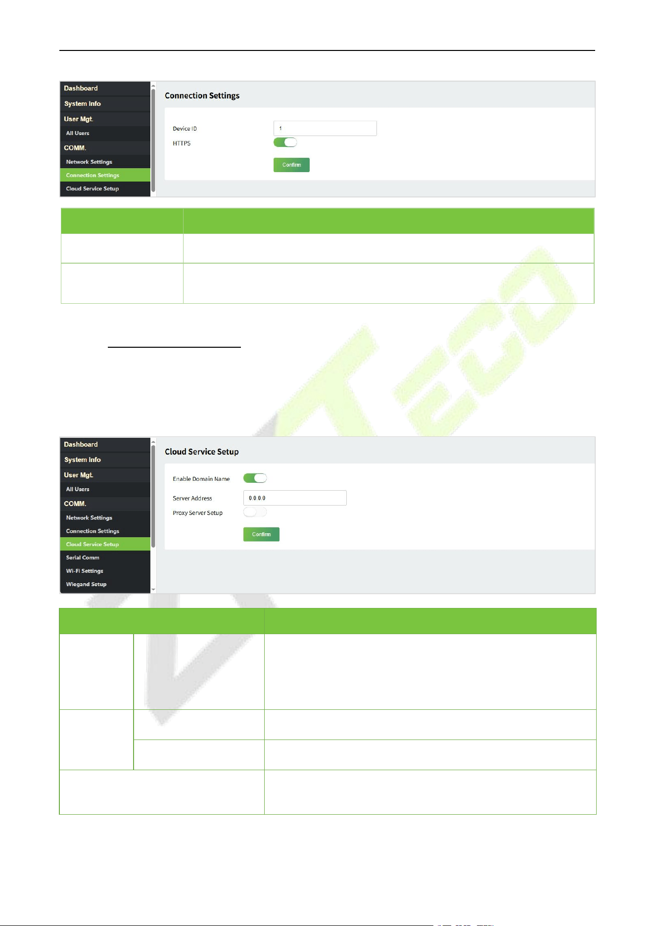
F34 User Manual
P a g e | 96 Copyright © 2026 ZKTECO CO., LTD. All rights reserved.
Function Name
Description
Device ID
It is the identification number of the device, which ranges between 0 and 255.
HTTPS
Based on HTTP, transmission encryption and identity authentication ensure the
security of the transmission process.
19.6.3 Cloud Service Setup
Click Cloud Service Setup on theWebServer.
Cloud Server Setup was used to connect to the ZKBio CVAccess / ZKBio Time / ZKBio Time Cloud software, please
refer to chapter 21/22/23.
Function Name
Description
Enable
Domain
Name
Cloud Server Address
Once this function is enabled, the domain name mode
“http://...” will be used, such as http://www.XYZ.com, while
“XYZ” denotes the domain name (when this mode is turned
ON).
Disable
Domain
Name
Cloud Server Address
IP address of the ADMS server.
Cloud Server Port
Port used by the ADMS server.
Proxy Server Setup
When you choose to enable the proxy, you need to set the IP
address and port number of the proxy server.
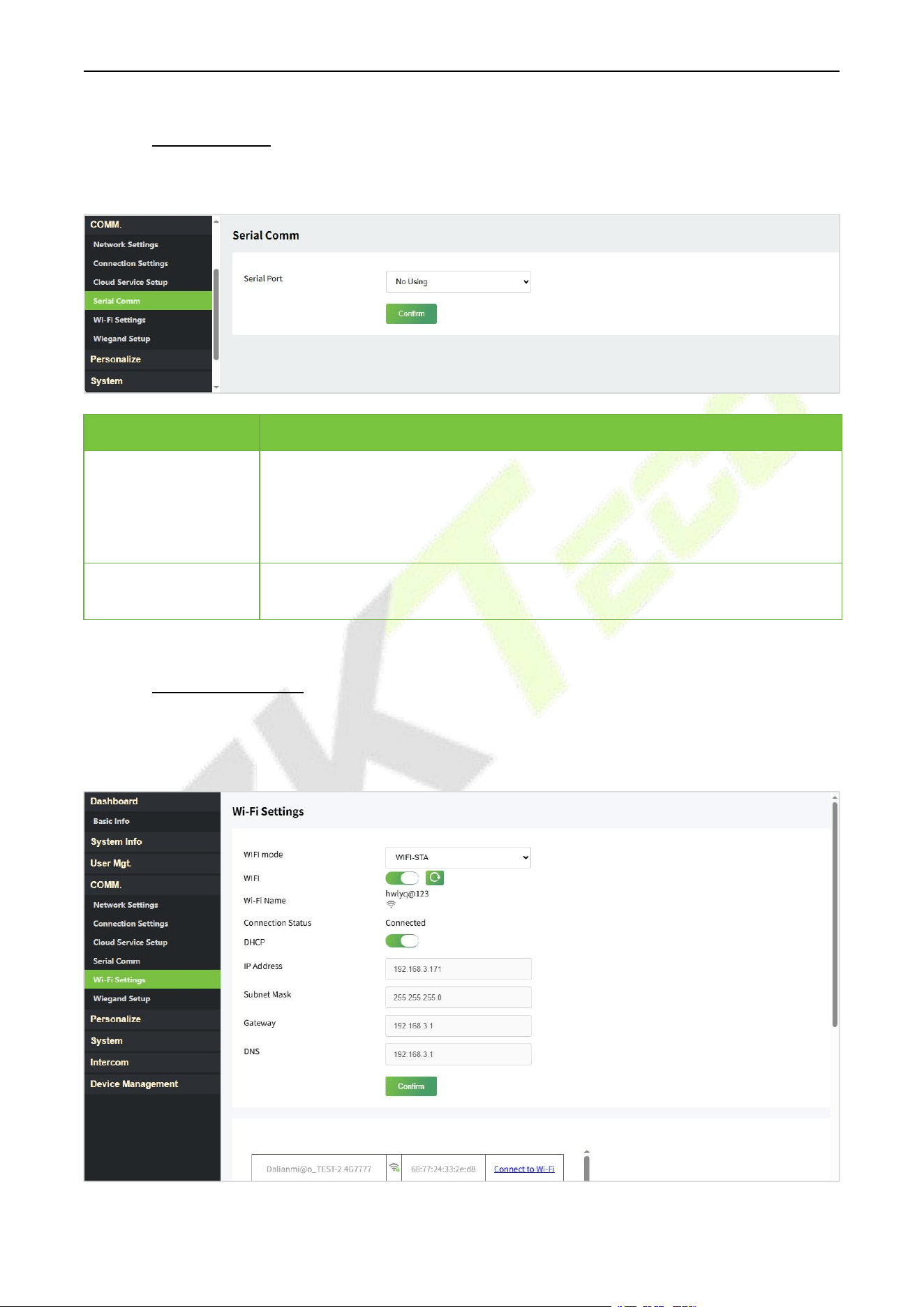
F34 User Manual
P a g e | 97 Copyright © 2026 ZKTECO CO., LTD. All rights reserved.
19.6.4 Serial Comm
Click Serial Comm on the WebServer.
Function Name
Description
Serial Port
No Using: No communication with the device through the serial port.
RS485(PC): Communicates with the device through RS485 serial port.
Primary Unit: When RS485 is used as the function of "Primary Unit", it can be
connected to a reader.
Baudrate
When the serial port is set as Primary Unit, the baudrate is 115200 by default
and cannot be modified.
19.6.5 Wi-Fi Settings
★
The device supports the Wi-Fi module, which is built-in within the hardware, to enable data transmission
via Wi-Fi and establish a wireless network environment.
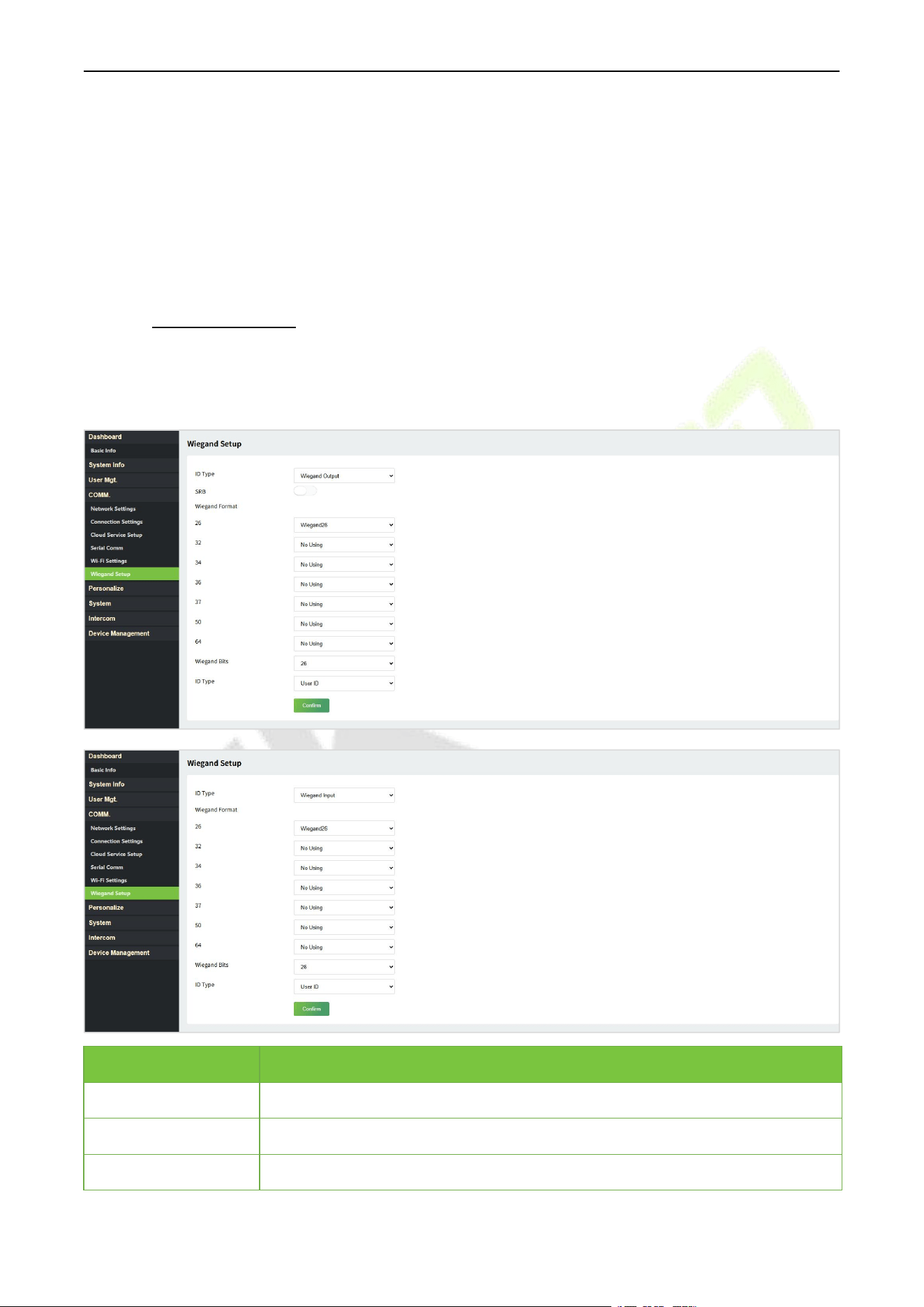
F34 User Manual
P a g e | 98 Copyright © 2026 ZKTECO CO., LTD. All rights reserved.
First set the WIFI mode, it is WIFI-STA by default.
When Wi-Fi is enabled, the device will search for the available Wi-Fi within the network range.
Click Connect to Wi-Fi after the required Wi-Fi name from the available list and input the correct
password, and then click [Confirm].
After successful verification, the connection status will display “Connected”.
19.6.6 Wiegand Setup
Click WiegandSetup on the WebServer.
It is used to set the Wiegand input and output parameters.
Function Name
Description
Wiegand Format
Its value can be 26 bits, 32 bits, 34 bits, 36 bits, 37 bits, 50 bits and 64 bits.
Wiegand Bits
The number of bits of the Wiegand data.
ID Type
Select between the User ID and card number.
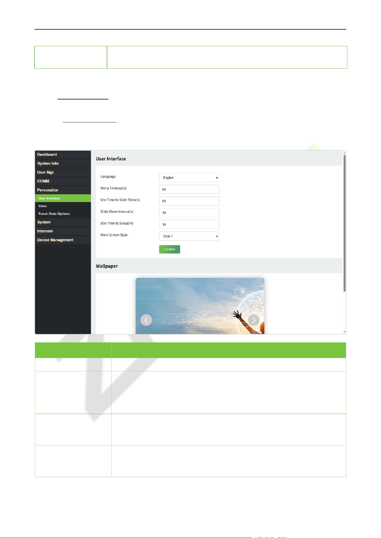
F34 User Manual
P a g e | 99 Copyright © 2026 ZKTECO CO., LTD. All rights reserved.
SRB
When SRB is enabled, the lock is controlled by the SRB to prevent the lock from
being opened due to device removal.
19.7 Personalize
19.7.1 User Interface
Click User Inteface on the WebServer.
Function Name
Description
Language
It helps to select the language of the device.
Menu Timeout (s)
When there is no operation, and the time exceeds the set value, the device
automatically goes back to the initial interface.
The function can either be disabled or set the required value between 60 and
99999 seconds.
Idle Time to Slide
Show (s)
When there is no operation, and the time exceeds the set value, a slide show
is displayed. The function can be disabled, or you may set the value between
3 and 999 seconds.
Slide Show Interval (s)
It is the time interval in switching between different slide show pictures. The
function can be disabled, or you may set the interval between 3 and 999
seconds.
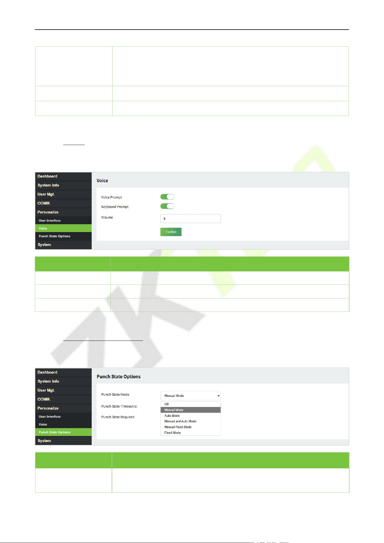
F34 User Manual
P a g e | 100 Copyright © 2026 ZKTECO CO., LTD. All rights reserved.
Idle Time to Sleep (m)
If the sleep mode is activated, and when there is no operation in the device,
then the device will enter standby mode.
This function can be disabled or set a value within 1 to 999 minutes.
Main Screen Style
The style of the main screen can be selected according to the user preference.
Wallpaper
Select the main screen wallpaper according to the user preference.
19.7.2 Voice
Click Voice on the WebServer.
Function Name
Description
Voice Prompt
Toggle to enable or disable the voice prompts during function operations.
Keyboard Prompt
Toggle to enable or disable the keypad sounds.
Volume
Adjust the volume of the device which can be set between 0 to 100.
19.7.3 Punch State Options
Click PunchState Options on the WebServer. It is only for time attendance terminal.
Function Name
Description
Punch State Mode
Off: Disable the punch state function. Therefore, the punch state key set
under Shortcut Key Mappings menu will become invalid.
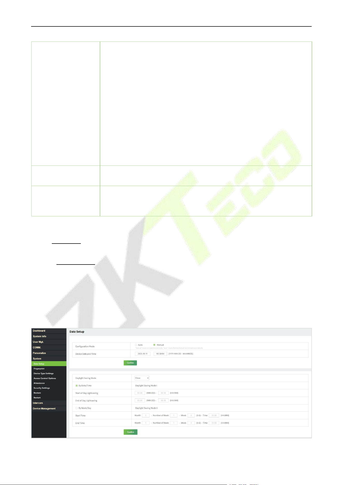
F34 User Manual
P a g e | 101 Copyright © 2026 ZKTECO CO., LTD. All rights reserved.
Manual Mode: Switch the punch state key manually, and the punch state key
will disappear after Punch State Timeout.
Auto Mode: The punch state key will automatically switch to a specific punch
status according to the predefined time schedule which can be set in the
Shortcut Key Mappings.
Manual and Auto Mode: The main interface will display the auto-switch
punch state key. However, the users will still be able to select alternative that
is the manual attendance status. After timeout, the manual switching to
punch state key will become auto-switch punch state key.
Manual Fixed Mode: After the punch state key is set manually to a particular
punch status, the function will remain unchanged until it is being manually
switched again.
Fixed Mode: Only the manually fixed punch state key will be shown. Users
cannot change the status by taping any other keys.
Punch State
Timeout(s)
It is the time for which the punch state displays. The value ranges from 5 to
999 seconds.
Punch State Required
Select whether an attendance state needs to be selected after verification.
ON: Attendance state needs to be selected after verification.
OFF: Attendance state need not requires to be selected after verification.
19.8 System
19.8.1 Date Setup
Click Date Setup on theWebServer.
Click Manual to manually set the date and time and click Confirm to save.
Select Open or Close the Daylight Saving Mode function. If opened, set the Daylight Saving Time
and End of Daylight Saving.
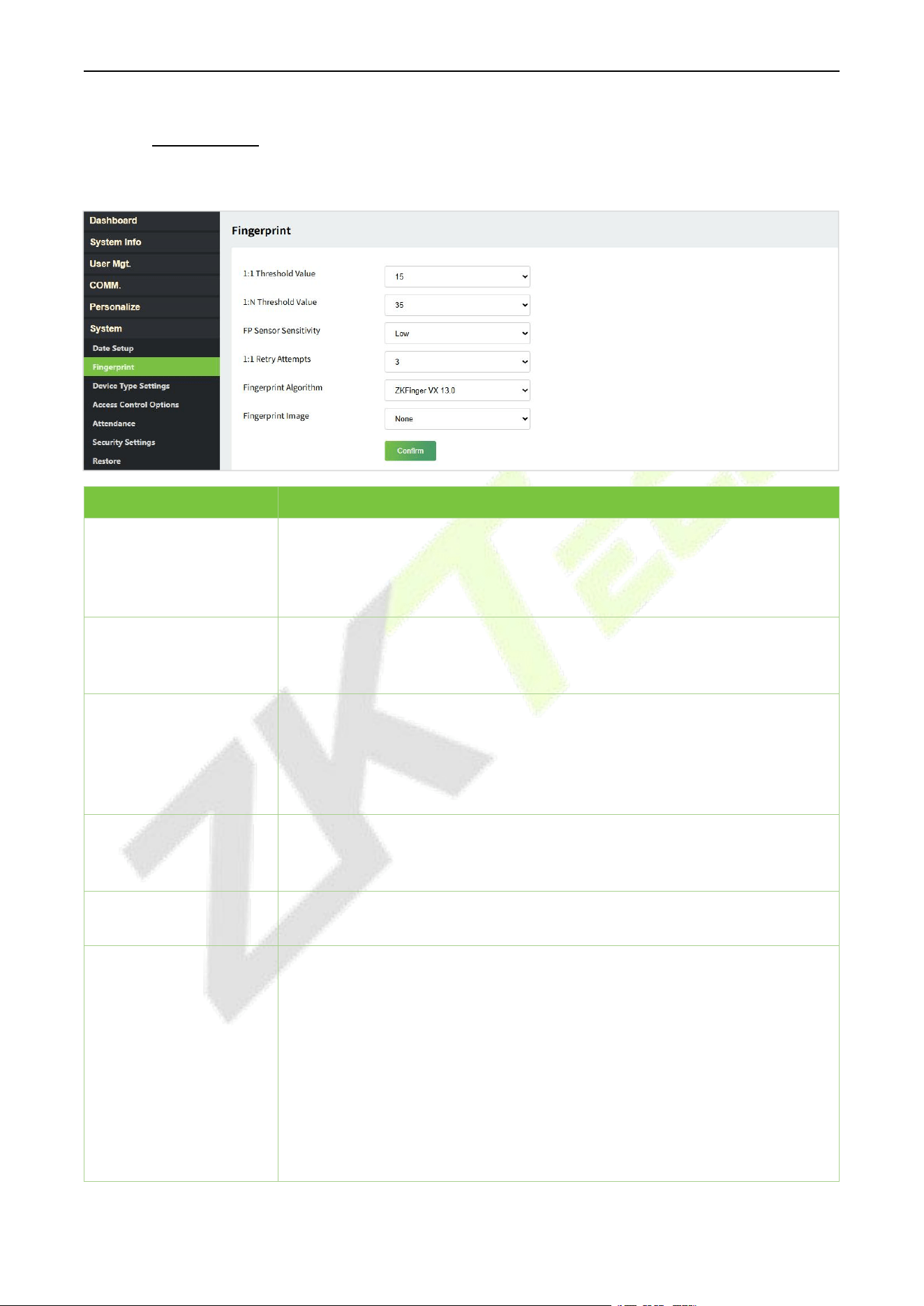
F34 User Manual
P a g e | 102 Copyright © 2026 ZKTECO CO., LTD. All rights reserved.
19.8.2 Fingerprint
Click Fingerprint on the WebServer.
Function Name
Description
1:1 Threshold Value
Under 1:1 verification method, the verification will only be successful when
the similarity between the acquired fingerprint data and the fingerprint
template associated with the entered user ID enrolled in the device is
greater than the set value.
1:N Threshold Value
Under 1:N verification method, the verification will only be successful when
the similarity between the acquired fingerprint data and the fingerprint
templates enrolled in the device is greater than the set value.
FP Sensor Sensitivity
To set the sensibility of fingerprint acquisition. It is recommended to use the
default level "Medium". When the environment is dry, resulting in slow
fingerprint detection, you can set the level to "High" to raise the sensibility;
when the environment is humid, making it hard to identify the fingerprint,
you can set the level to "Low".
1:1 Retry Times
In 1:1 Verification, users might forget the registered fingerprint, or press the
finger improperly. To reduce the process of re-entering user ID, retry is
allowed.
Fingerprint Algorithm
Fingerprint algorithm version. Default support ZKFinger VX13.0, can change
to ZKFinger VX10.0.
Fingerprint Image
To set whether to display the fingerprint image on the screen during
fingerprint enrollment or verification. Four choices are available:
Show for Enroll: to display the fingerprint image on the screen only during
enrollment.
Show for Match: to display the fingerprint image on the screen only during
verification.
Always Show: to display the fingerprint image on screen during enrollment
and verification.
None: not to display the fingerprint image.
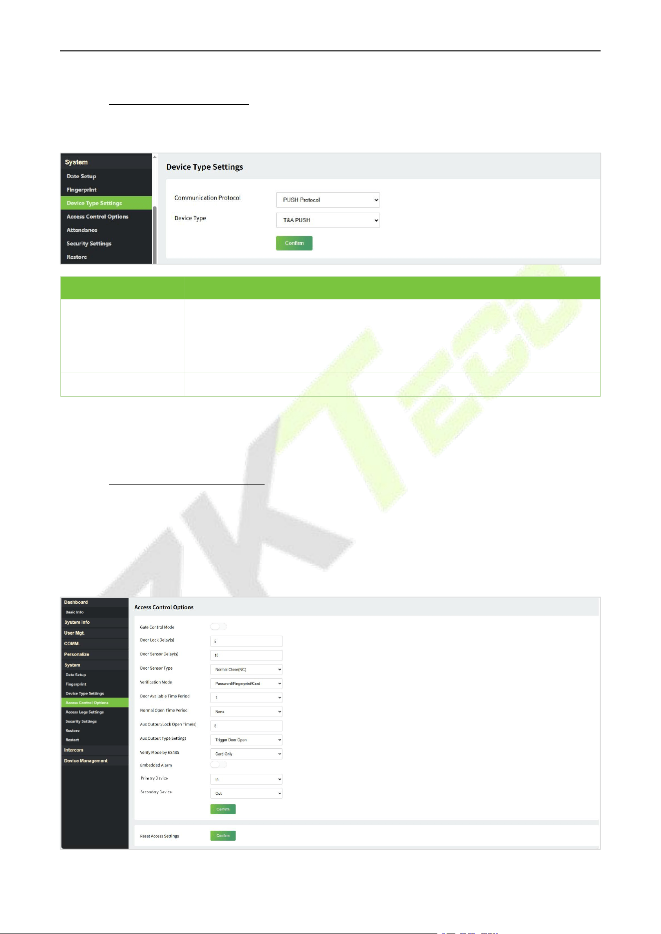
F34 User Manual
P a g e | 103 Copyright © 2026 ZKTECO CO., LTD. All rights reserved.
19.8.3 Device Type Settings
Click DeviceTypeSettings on theWebServer.
Function Name
Description
Communication
Protocol
Set the device communication protocol. It is BEST Protocol by default, which is
suitable for ZKBio Zlink.
PUSH Protocol: It can be set as A&C PUSH (which is suitable for ZKBio
CVAccess) or T&A PUSH (which is suitable for ZKBio Time Cloud/ZKBio Time).
Device Type
Set the device as an access control terminal or attendance terminal.
Note: After changing the device type, the device will delete all the data and restart, and some functions
will be adjusted accordingly.
19.8.4 Access Control Options
Click Access ControlOptions on the WebServer.
On the Access Control interface to set the parameters of the control lock of the terminal and related
equipment.
Access Control Terminal:

F34 User Manual
P a g e | 104 Copyright © 2026 ZKTECO CO., LTD. All rights reserved.
Function Name
Description
Gate Control Mode
It toggles between ON or OFF switch to get into gate control mode or not.
When set to ON, the interface removes the Door Lock Delay, Door Sensor
Delay, and Door Sensor Type options.
Door Lock Delay (s)
The length of time that the device controls the electric lock to be in unlock
state. Valid value: 1~99 seconds.
Door Sensor Delay (s)
If the door is not locked and is left open for a certain duration (Door Sensor
Delay), an alarm will be triggered.
The valid value of Door Sensor Delay ranges from 1 to 255 seconds.
Door Sensor Type
There are three Sensor types: None, Normal Open, and Normal Close.
None: It means the door sensor is not in use.
Normal Open: It means the door is always left open when electric power is
on.
Normal Close: It means the door is always left closed when electric power is
on.
Verification Mode
The supported verification mode includes Password/Fingerprint/Card,
Fingerprint Only, User ID Only, Password, Card Only, Fingerprint/Password,
Fingerprint/Card, User ID + Fingerprint, Fingerprint + Password, Fingerprint
+ Card, Fingerprint + Password + Card, Password + Card, Password/Card,
User ID + Fingerprint + Password, Fingerprint + (Card/User ID).
Door Available Time
Period
It sets the timing for the door so that the door is accessible only during that
period.
Normal Open Time
Period
It is the scheduled time-period for "Normal Open" mode so that the door is
always open during this period.
Aux Output/Lock Open
Time(s)
Sets the door unlock time period of the auxiliary terminal device.
Aux Output Type
Settings
Auxiliary output types include None, Trigger door open, Trigger Alarm,
Trigger door open and Alarm.
Verify Mode by RS485
When the RS485 reader function is turned on, the verification method is
used when the device is used as a primary or a secondary.
Embedded Alarm
If enabled, it transmits a sound alarm or disassembly alarm from the local.
When the door is closed or the verification is successful, the system cancels
the alarm from the local.
Primary Device
While configuring the primary and secondary devices, you may set the state
of the primary as Out or In.
Out: A record of verification on the primary device is a check-out record.
In: A record of verification on the primary device is a check-in record.
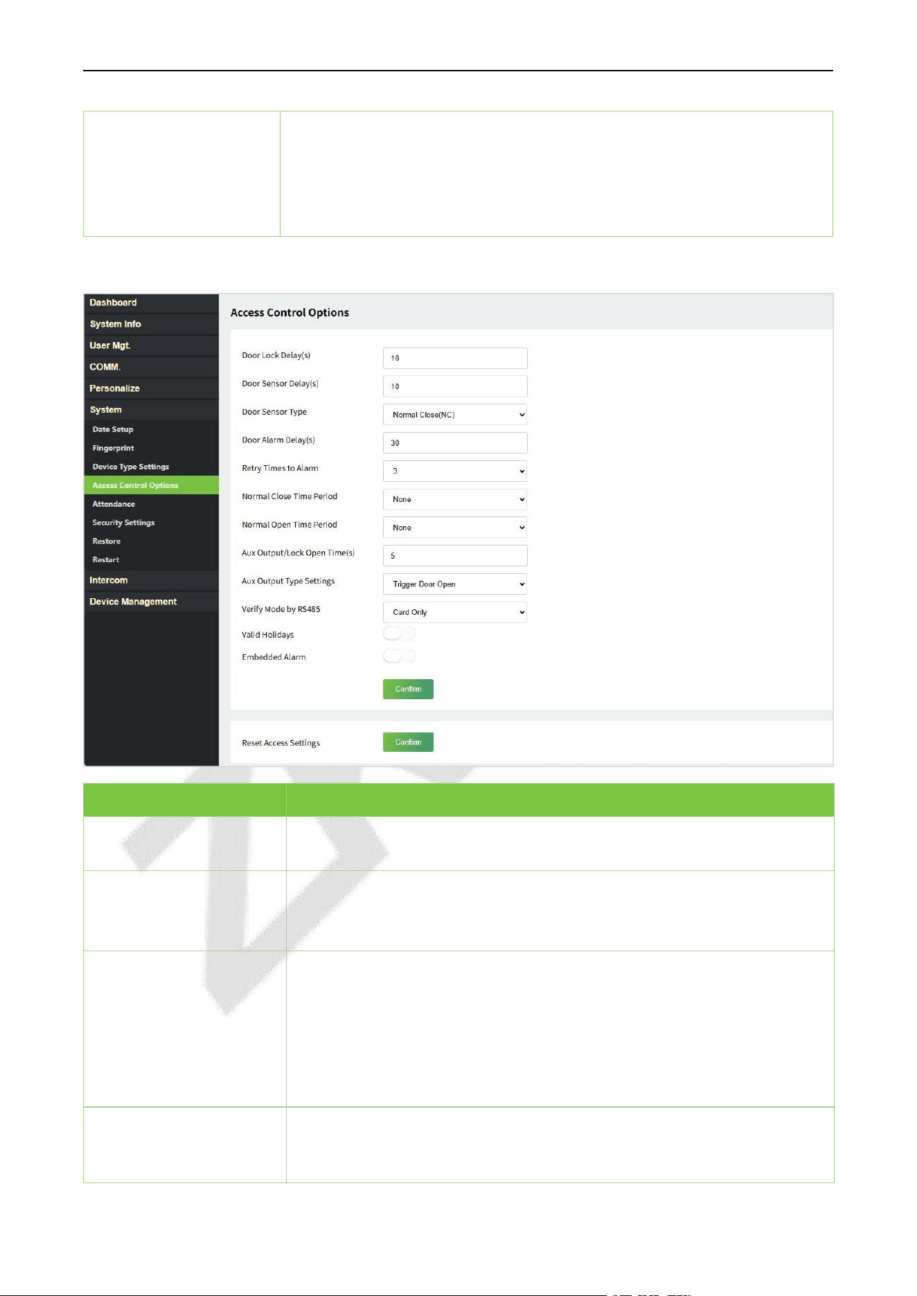
F34 User Manual
P a g e | 105 Copyright © 2026 ZKTECO CO., LTD. All rights reserved.
Secondary Device
While configuring the primary and secondary devices, you may set the state
of the secondary as Out or In.
Out: A record of verification on the secondary device is a check-out record.
In: A record of verification on the secondary device is a check-in record.
Attendance Terminal:
Function Name
Description
Door Lock Delay (s)
The length of time that the device controls the electric lock to be in unlock
state. Valid value: 0 to 10 seconds.
Door Sensor Delay (s)
If the door is not locked and is left open for a certain duration (Door Sensor
Delay), an alarm will be triggered.
The valid value of Door Sensor Delay ranges from 1 to 255 seconds.
Door Sensor Type
There are three Sensor types: None, Normal Open, and Normal Close.
None: It means the door sensor is not in use.
Normal Open (NO): It means the door is always left open when electric
power is on.
Normal Close (NC): It means the door is always left closed when electric
power is on.
Door Alarm Delay(s)
When the state of the door sensor is inconsistent with that of the door
sensor type, alarm will be triggered after a time period; this time period is
the Door Alarm Delay (the value ranges from 1 to 999 seconds).
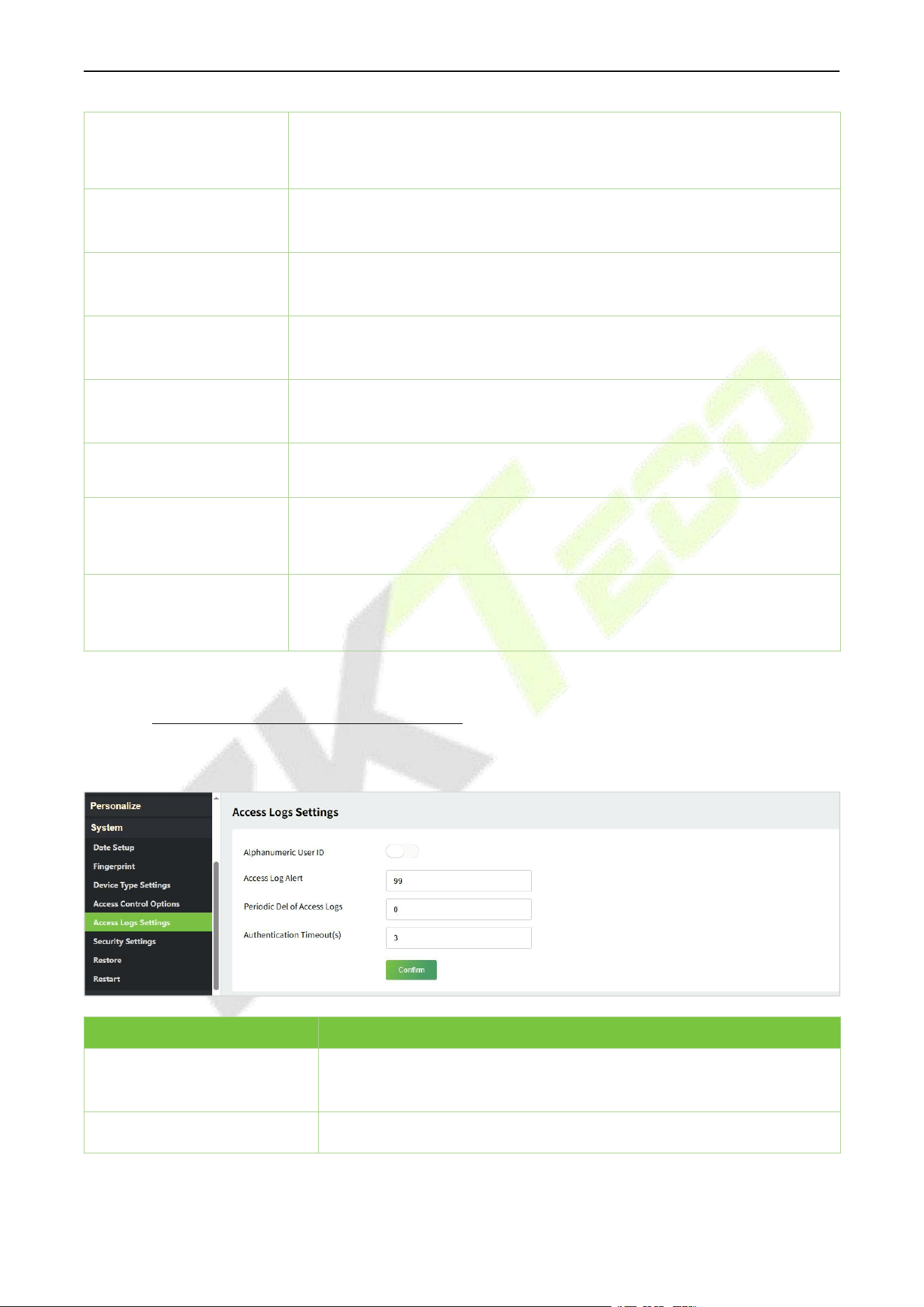
F34 User Manual
P a g e | 106 Copyright © 2026 ZKTECO CO., LTD. All rights reserved.
Retry Times to Alarm
When the number of failed verifications reach the set value (value ranges
from 1 to 9 times), the alarm will be triggered. If the set value is None, the
alarm will not be triggered after failed verification.
Normal Close Time
Period
It is the scheduled time-period for "Normal Close" mode so that the door is
always closed during this period.
Normal Open Time
Period
It is the scheduled time-period for "Normal Open" mode so that the door is
always open during this period.
Aux Output/Lock Open
Time(s)
Sets the door unlock time period of the auxiliary terminal device.
Aux Output Type
Settings
Auxiliary output types include None, Trigger door open, Trigger Alarm,
Trigger door open and Alarm.
Verify Mode by RS485
When the RS485 reader function is turned on, the verification method is
used when the device is used as a primary or a secondary.
Valid Holidays
To set if Normal Close Time Period or Normal Open Time Period settings
are valid in set holiday time period. Choose [ON] to enable the set NC or
NO time period in holiday.
Embedded Alarm
If enabled, it transmits a sound alarm or disassembly alarm from the local.
When the door is closed or the verification is successful, the system cancels
the alarm from the local.
19.8.5 Access Logs Settings/Attendance
Click Access Logs Settings/Attendance onthe WebServer.
Function Name
Description
Duplicate Punch Period(m)
Within a set time period (unit: minutes), the duplicated attendance
record will not be reserved (value ranges from 1 to 999999 minutes).
Alphanumeric User ID
Enable/Disable the alphanumeric as User ID.
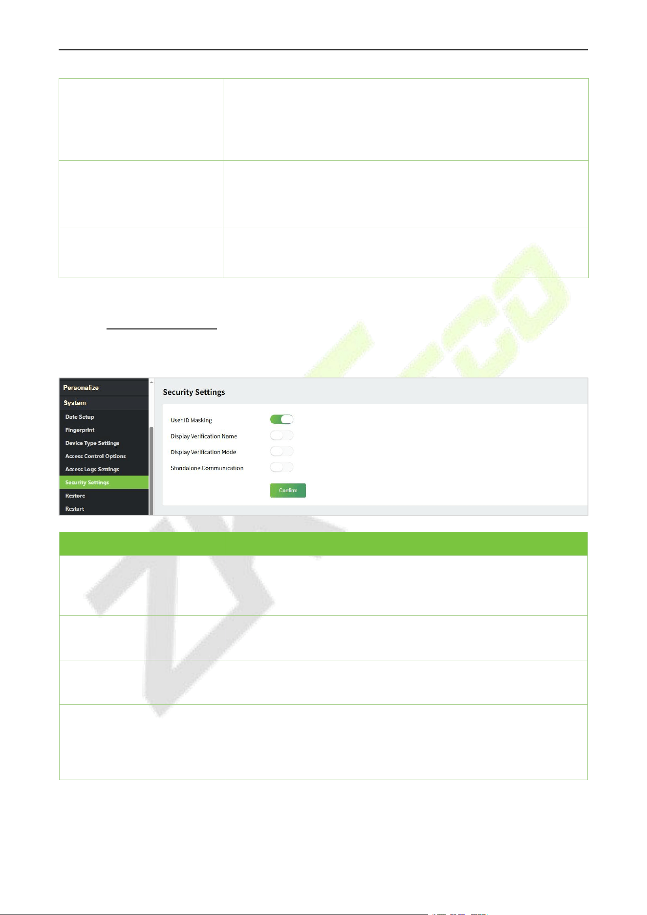
F34 User Manual
P a g e | 107 Copyright © 2026 ZKTECO CO., LTD. All rights reserved.
Access/Attendance Log Alert
When the record space of the attendance/access reaches the
maximum threshold value, the device automatically displays the
memory space warning.
Users may disable the function or set a valid value between 1 and 9999.
Periodic Del of Access
Logs/T&A Data
When access/attendance logs reach its maximum capacity, the device
automatically deletes a set of old access/attendance logs.
Users may disable the function or set a valid value between 1 and 999.
Authentication Timeout(s)
The amount of time taken to display a successful verification message.
Valid value: 1 to 9 seconds.
19.8.6 Security Settings
Click Security Settings on the WebServer.
Function Name
Description
User ID Masking
When enabled, and then the user is successfully compared and
verified, the User ID in the displayed verification result will be replaced
with an * to achieve secure protection of sensitive private data.
Display Verification Name
Set whether to display the username in the verification result
interface.
Display Verification Mode
Set whether to display the verification mode in the verification result
interface.
Standalone Communication
By default, this function is disabled. It is used to connect the C/S
software (like ZKTime.Net, etc.). When it is switched on, a security
prompt appears, and you need to set the Comm Key, the device will
restart after you confirm.
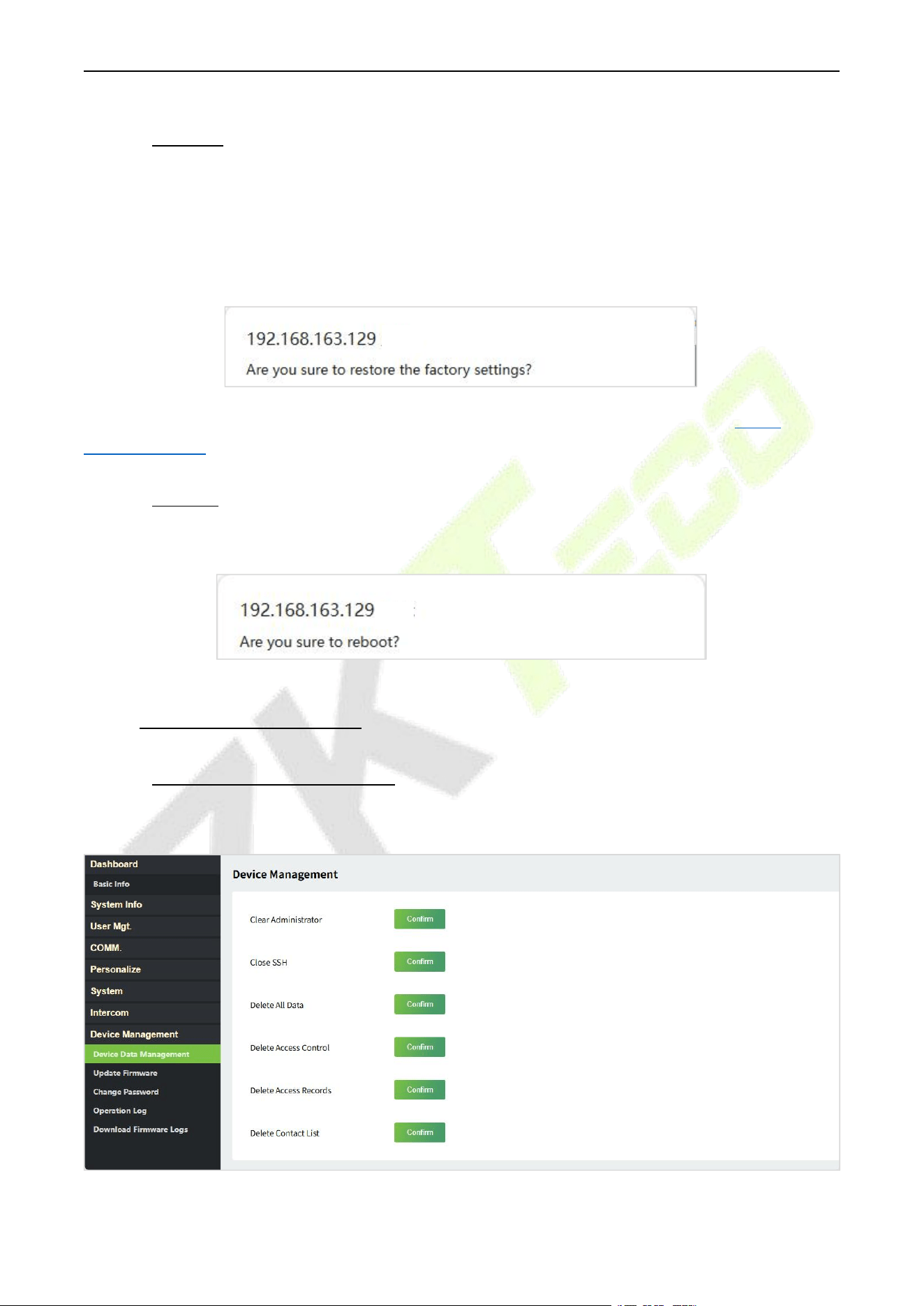
F34 User Manual
P a g e | 108 Copyright © 2026 ZKTECO CO., LTD. All rights reserved.
19.8.7 Restore
Click Restoreon the WebServer, and it will pop up the following prompt box. Click Yes to restore the
factory settings.
The Restore function restores the device settings such as communication and system settings to the
default factory settings (this function does not clear registered user data).
Note: After reset, the IP of the device is restored to the original 192.168.1.201, please refer to 18.6.1
Network Settings to modify the IP.
19.8.8 Restart
Click Restart on the WebServer, and it will pop up the following prompt box. Click Yes to reboot.
19.9 Device Management
19.9.1 Device Data Management
Click DeviceDataManagement on the WebServer.
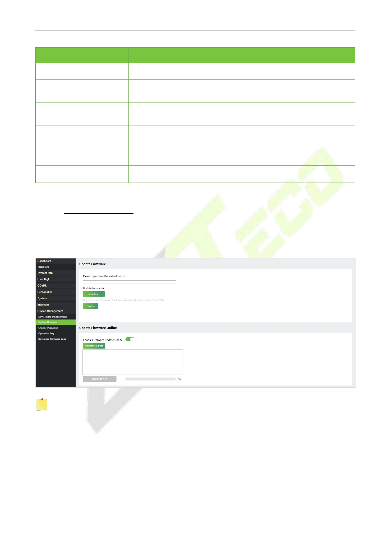
F34 User Manual
P a g e | 109 Copyright © 2026 ZKTECO CO., LTD. All rights reserved.
Function Name
Description
Clear Administrator
Choose whether to change the super administrator into a normal user.
Close SSH
SSH is used to enter the background of the device for maintenance,
choose whether to close the SSH.
Delete All Data
To delete the information and attendance logs/access records of all
registered users.
Delete Access Control
To delete all the access data.
Delete Access/Attendance
Records
To delete all the access/attendance records.
Delete Contact List
To delete all the contact list in the device.
19.9.2 Update Firmware
Click UpdateFirmware on theWebServer.
Select an upgrade file and click Confirm to complete firmware upgrade operation.
Note: If the upgrade file is needed, please contact our technical support. Firmware upgrade is not
recommenced under normal circumstances.
You can also choose to update firmware online. Click Detection upgrade it may have the following 3
scenarios:
If the query fails, the interface will prompt "Query Failed".
If the firmware version of the device is latest, it will prompt that the current firmware version is
already the latest.
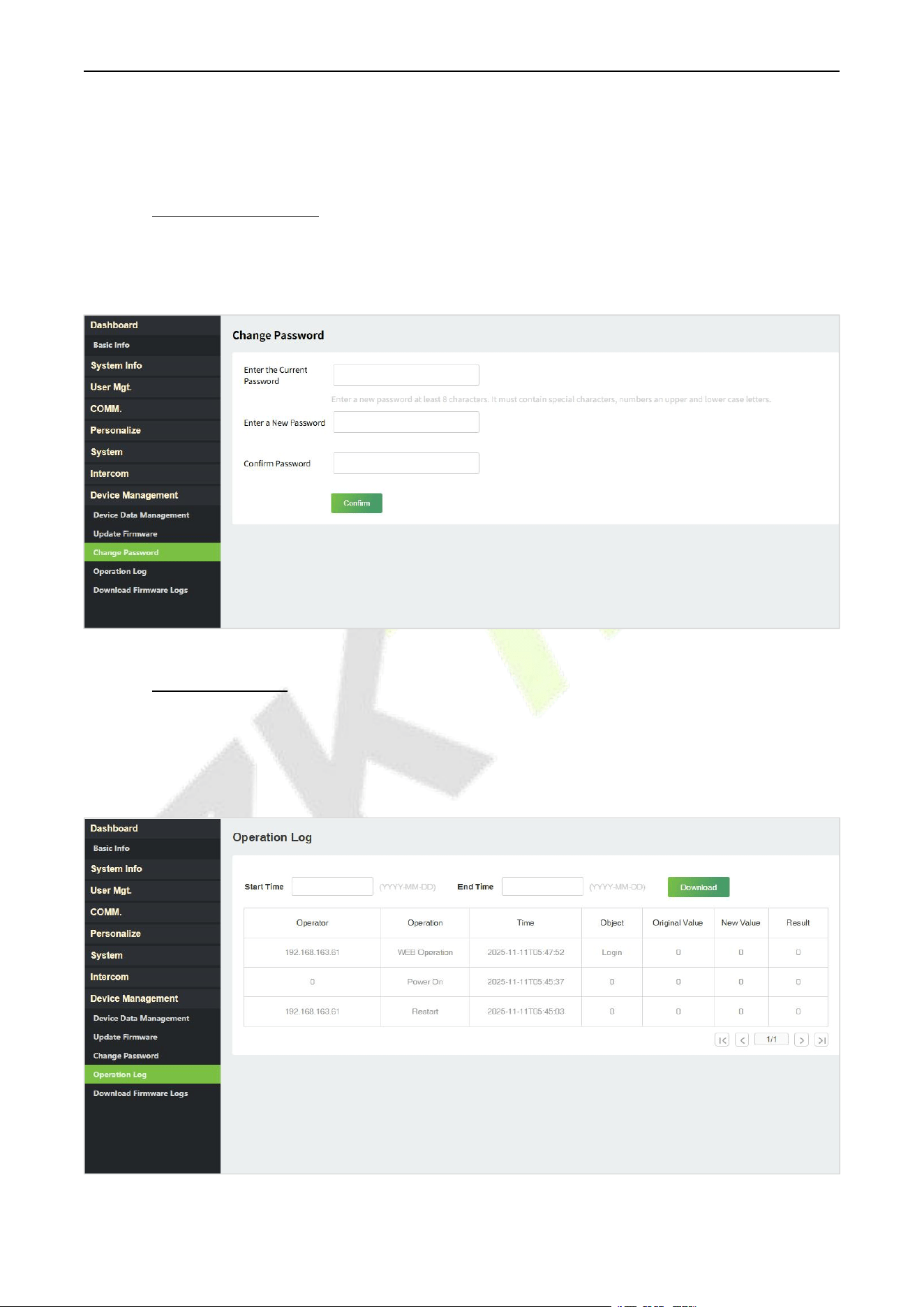
F34 User Manual
P a g e | 110 Copyright © 2026 ZKTECO CO., LTD. All rights reserved.
If the firmware version of the device is not the latest, the version number and change log of the latest
version will be displayed. Users can choose whether to update to the latest firmware version.
19.9.3 Change Password
Click Change Password onthe WebServer.
In this interface, youcan change the password of WebServer.
19.9.4 Operation Log
Click Operation Log on the WebServer.
All the user’s operation records on thedevice orWebServer are saved.Users can search and download these logs
bytime.
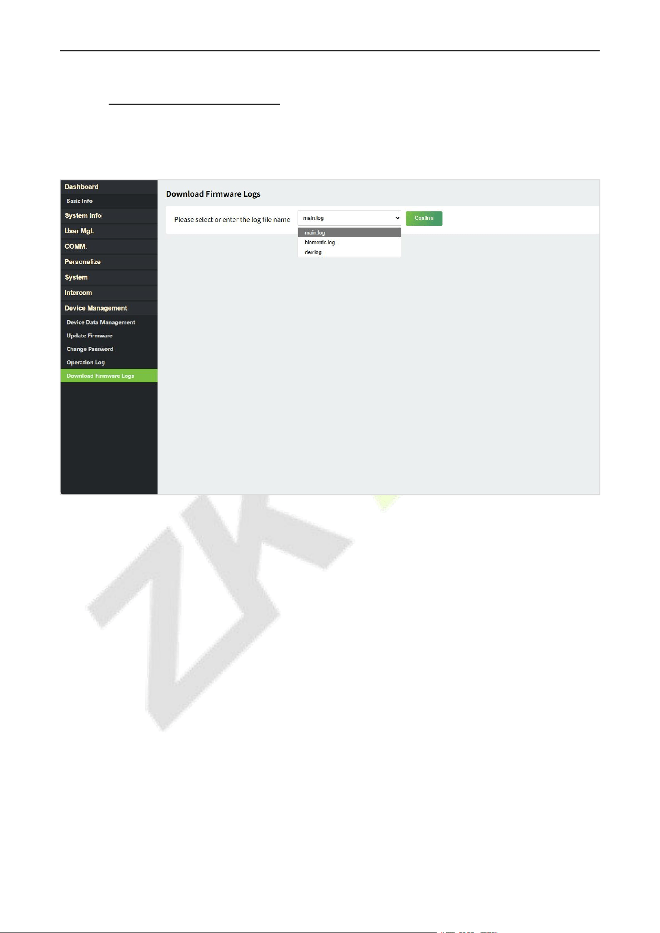
F34 User Manual
P a g e | 111 Copyright © 2026 ZKTECO CO., LTD. All rights reserved.
19.9.5 Download Firmware Logs
Click Download Firmware Logs onthe WebServer.
In this interface, youcan selectdownload themain, biometric, or dev.log.
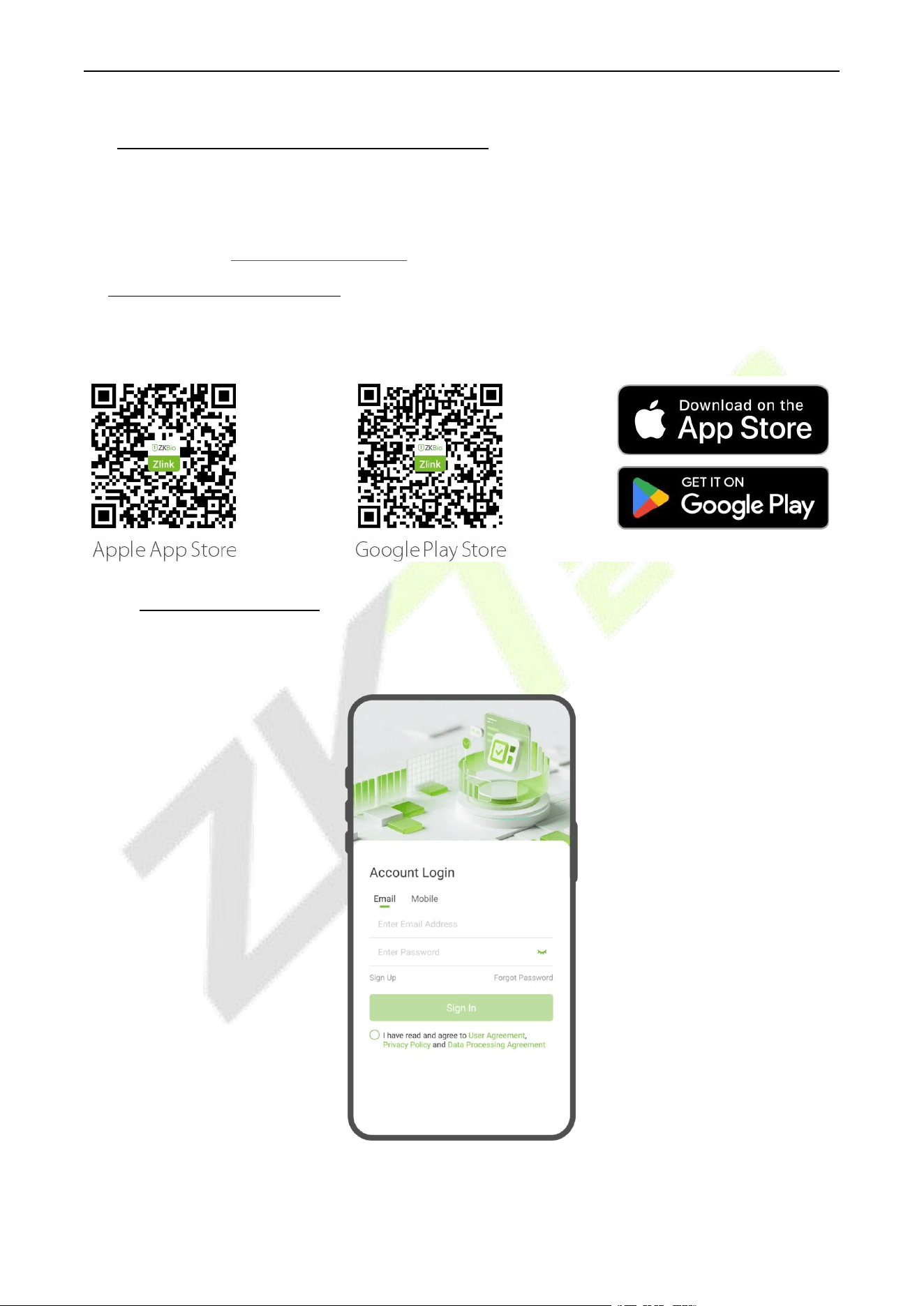
F34 User Manual
P a g e | 112 Copyright © 2026 ZKTECO CO., LTD. All rights reserved.
20 Connecting to ZKBio Zlink App
The App pages may vary depending on the version, and the document is for reference only.
Change the device communication protocol to BEST protocol, then the device can be managed by ZKBio
Zlink, please refer to 9.4 Device Type Settings.
Download the ZKBio Zlink App
Search for the "ZKBio Zlink" App in the iOS App Store or Google Play Store. Or scan the QR code below to
install the app.
20.1 Login to the App
Enter your registered account and password, check “I have read and agree to User Agreement, Privacy
Policy and Data Processing Agreement” and click Sign In to log in to the App.
Note: For more operations, refer to the ZKBio Zlink App's user manual.
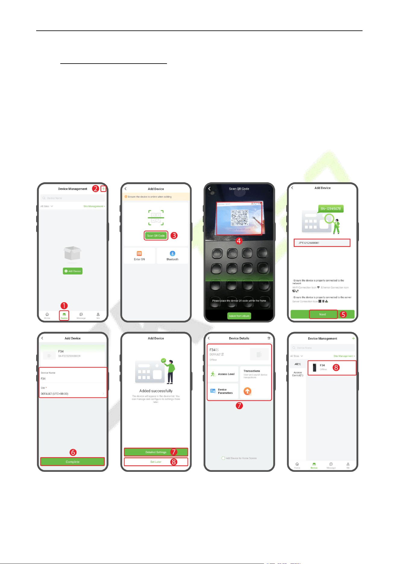
F34 User Manual
P a g e | 113 Copyright © 2026 ZKTECO CO., LTD. All rights reserved.
20.2 Add Device on the App
Access the ZKBio Zlink App and click on [Device] > the + icon in the top-right corner to access the
“Add Device” screen. (See diagram step 1,2)
Then click [Scan QR Code] to scan the QR code on the device. After scanning the QR code to find the
device, click [Next]. (See diagram step 3,4,5)
Enter the device name and specify the device to a site. Click [Complete] to complete the addition.
(See diagram step 6)
Once successfully added, the device is displayed in the list of the device interface. Click [Detailed
Settings]/[Set Later] to enter the corresponding interface. (See diagram step 7,8)
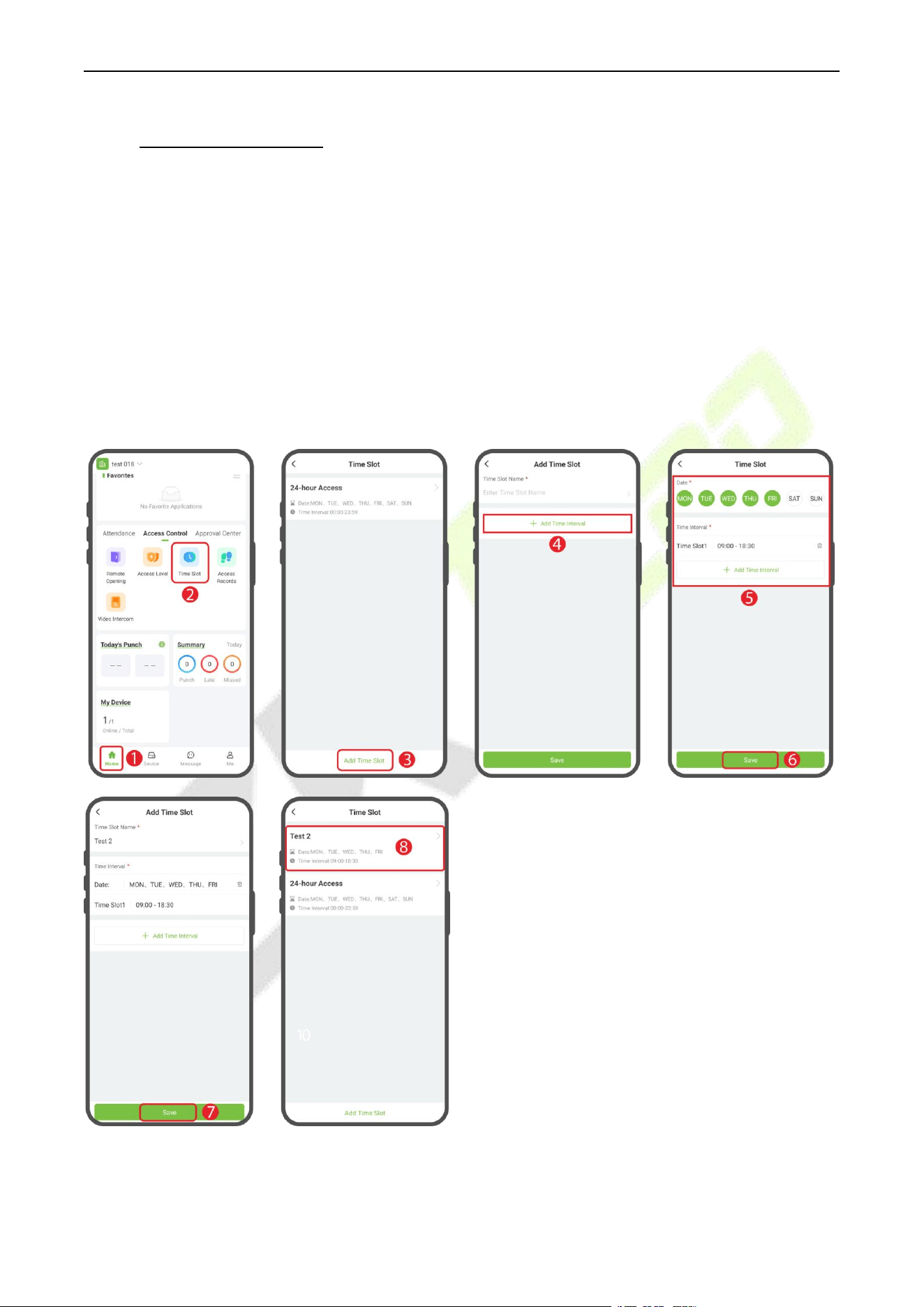
F34 User Manual
P a g e | 114 Copyright © 2026 ZKTECO CO., LTD. All rights reserved.
20.3 Set Access Levels
Click [Home] > [Access Control] > [Time Slot] > [Add Time Slot] to add a time slot. (See diagram
step 1,2,3)
Set the time slot name and click [Add Time Interval] to add the time intervals, then click [Save]. The
time slot will then appear in the list. (See diagram step 4,5,6,7,8)
Note: There is a default timeslot named 24-hour Access in the system.
Click [Home] > [Access Level] > the + icon in the top-right corner to add an access level. (See diagram
step 9,10)
Set the name, select the time slot, device, and persons, and click [Save] to synchronize the access
level to the device. The access level will then appear in the list. (See diagram step 11,12)
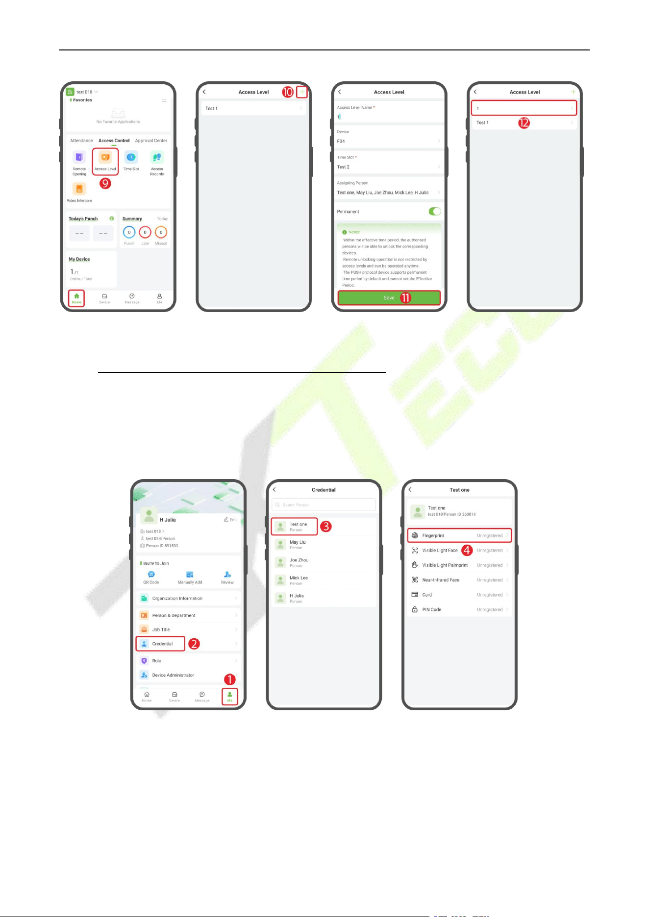
F34 User Manual
P a g e | 115 Copyright © 2026 ZKTECO CO., LTD. All rights reserved.
20.4 Register Verification Mode on the App
Once you have added persons to the device, you can register verification modes to them.
Note: It must be based on the functions actually supported by the device.
Click [Me] > [Credential] to enter theCredential screen, select the person who needs to register verification mode.
(See diagram step 1,2,3,4)
Register Password
In the Details interface, click [PIN Code] and enter the password in the setting screen, then click [Complete]. (See
diagram step 1,2)
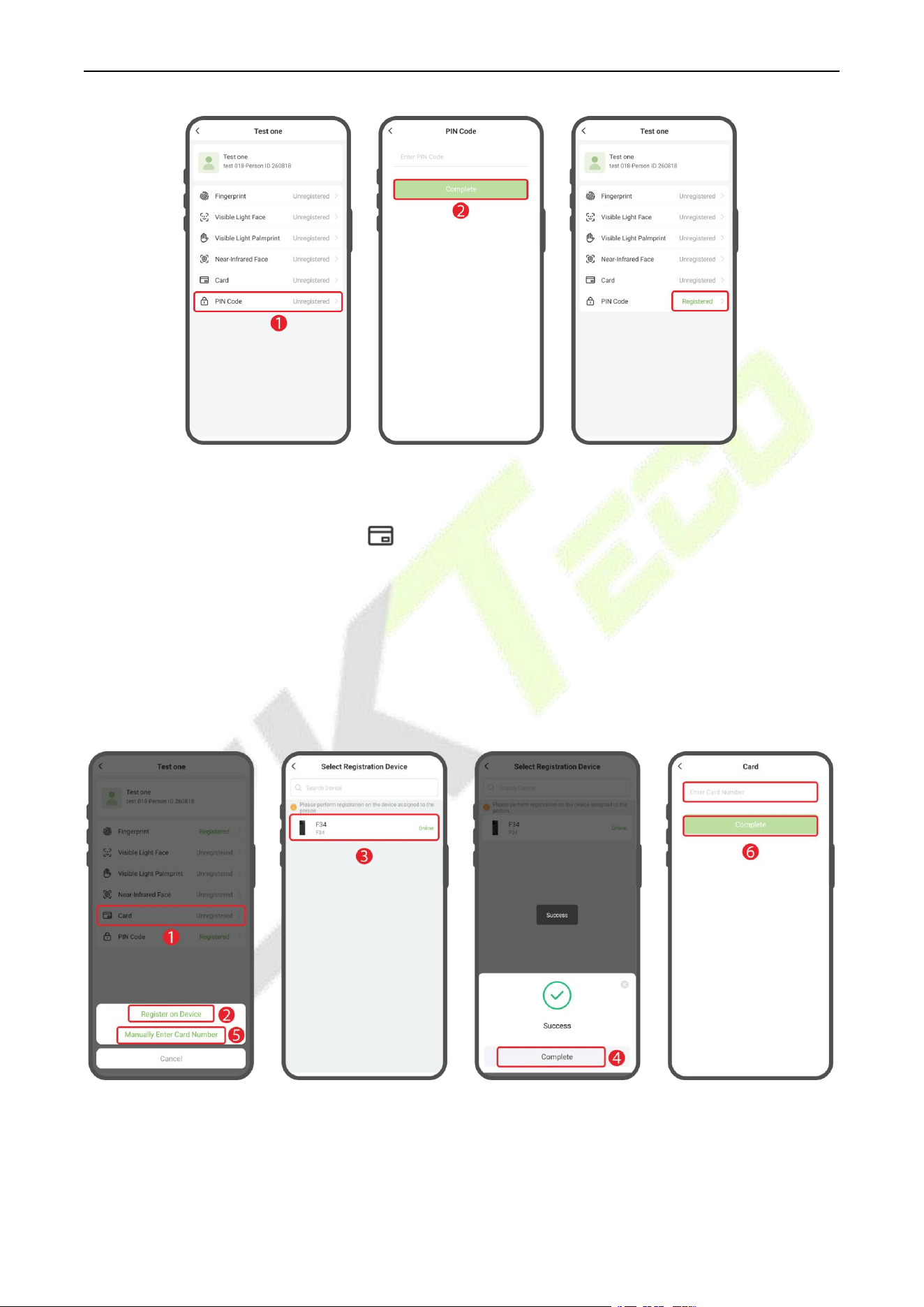
F34 User Manual
P a g e | 116 Copyright © 2026 ZKTECO CO., LTD. All rights reserved.
Register Card
In the Details interface, click on the icon. You can select Register on Device or Manually Enter Card
Number. If you want to register on device, then click Register on Device. (See diagram step 1,2)
Select the registration device, at the same time, the device displays the Enroll Card Number interface.
Place the card in the swipe area, when the app displays “Success”, it means the card is successfully
registered. (See diagram step 3,4)
When you click [Manually Enter Card Number], simply enter the card number directly in the pop-up
window. (See diagram step 5,6)
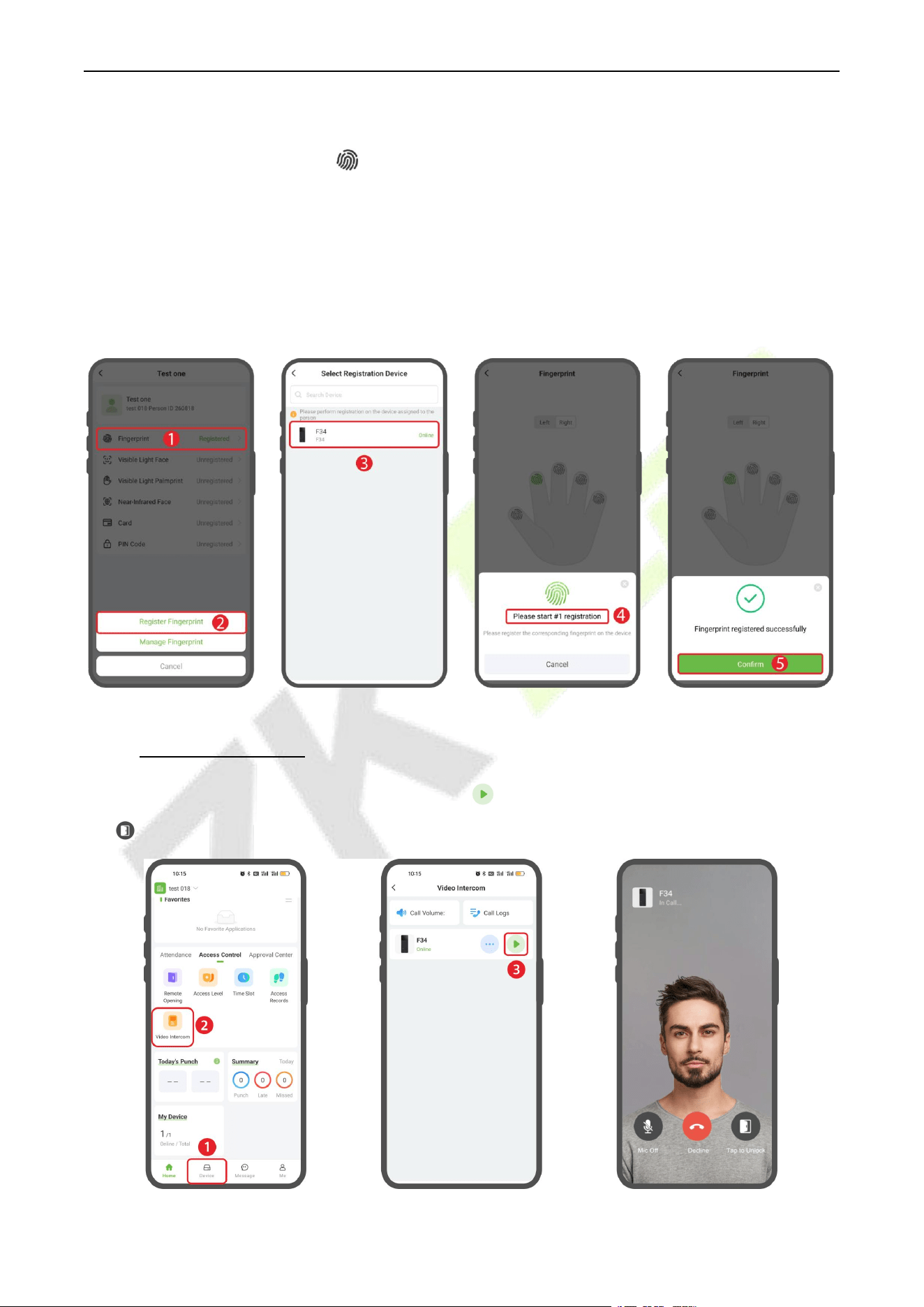
F34 User Manual
P a g e | 117 Copyright © 2026 ZKTECO CO., LTD. All rights reserved.
Register Fingerprint
In the Details interface, click the icon > [Register Fingerprint], select the device and the fingerprint to
register. When selecting a device for registration, the device will prompt “Please press your finger”
and press 3 times on the collector after hearing the prompt. (See diagram step 1,2,3,4)
Click [Confirm] to return. (See diagram step 5)
When you hear the message “Registration is successful”, the registration is successful. And you can
repeat the above operation to register other fingers.
20.5 Video Intercom
Click [Device] > [Video Intercom], then click the icon to call this device. Tap the “Tap to Unlock”
icon to remotely unlock the door.
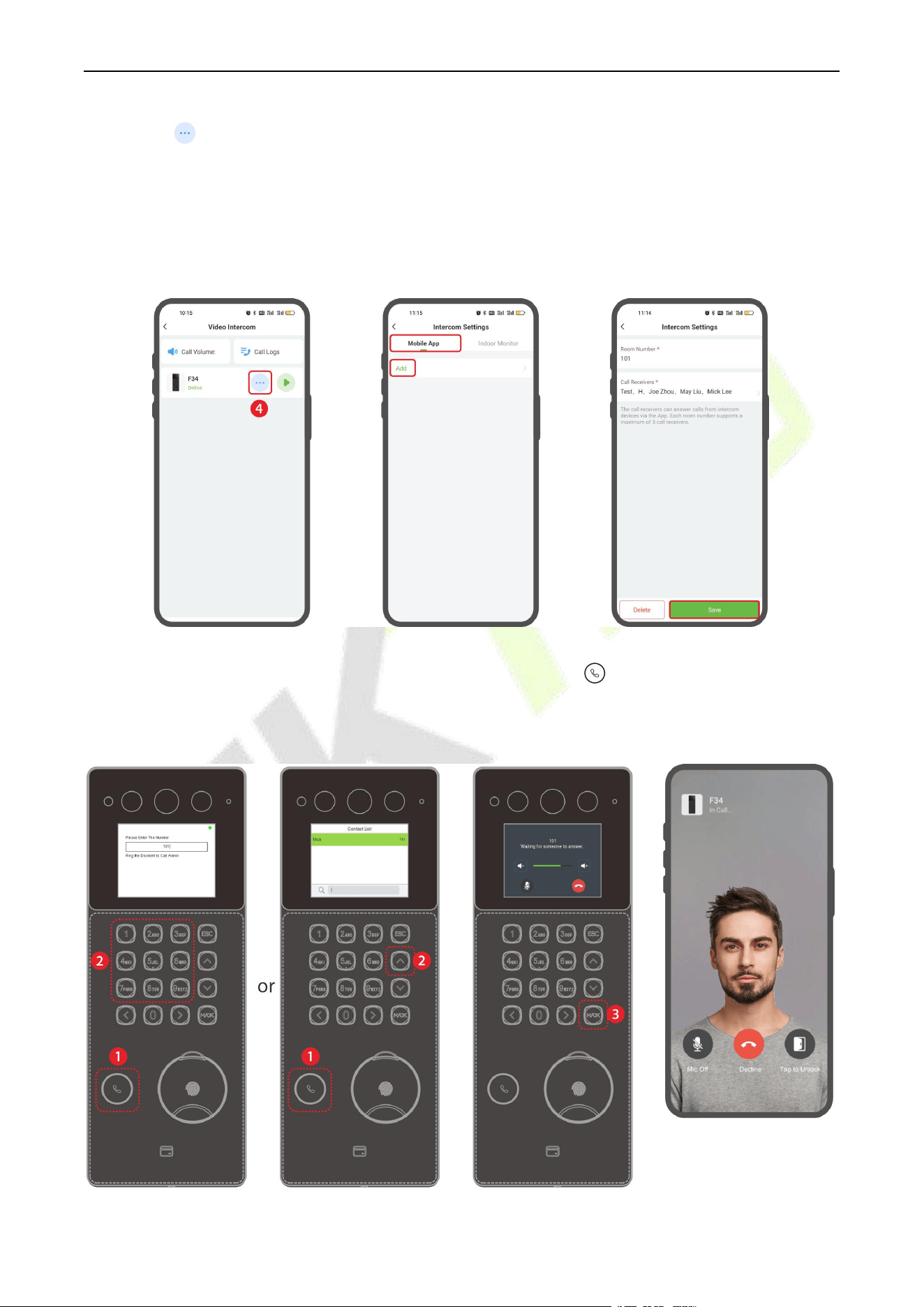
F34 User Manual
P a g e | 118 Copyright © 2026 ZKTECO CO., LTD. All rights reserved.
Tap the icon to enter the intercom settings interface. Click [Mobile App] > [Add] to link personnel
who can answer incoming calls via the app.
Room Number: Customize the number of the person.
Person: One or multiple persons can be selected. If multiple persons are selected, all the persons will
receive the call when the device calls the number.
After completing the setup, press the video intercom button on the device. In the pop-up
interface, enter the call number or press the UP key to open the contact list and search for the person
you wish to call. Then press the M/OK button to initiate the call.
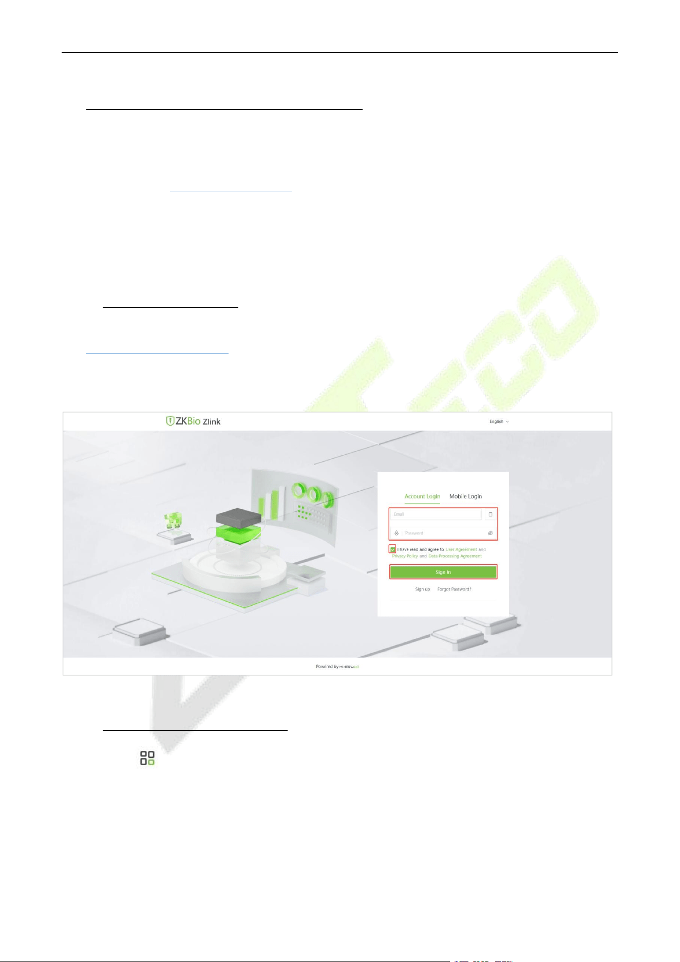
F34 User Manual
P a g e | 119 Copyright © 2026 ZKTECO CO., LTD. All rights reserved.
21 Connecting to ZKBio Zlink Web
The web pages may vary depending on the version, and the document is for reference only.
Change the device communication protocol to BEST protocol, then the device can be managed by ZKBio
Zlink, please refer to 9.4 Device Type Setting.
Users can use the created account to access ZKBio Zlink Web to connect devices, add new personnel,
register the verification method of registered personnel, synchronize personnel to devices and query
records.
21.1 Login to the Web
1. Please open the recommended browser and enter the IP address to access the ZKBio Zlink Web:
http://zlink.minervaiot.com.
2. Enter your Email ID and password on the login screen, check “I have read and agree to User
Agreement and Privacy Policy and Data Processing Agreement” and click [Sign In] to login.
21.2 Add Device on the Web
1. Click the icon on the top left corner, and click [Device Center] > [Device] to enter the device
setting interface.
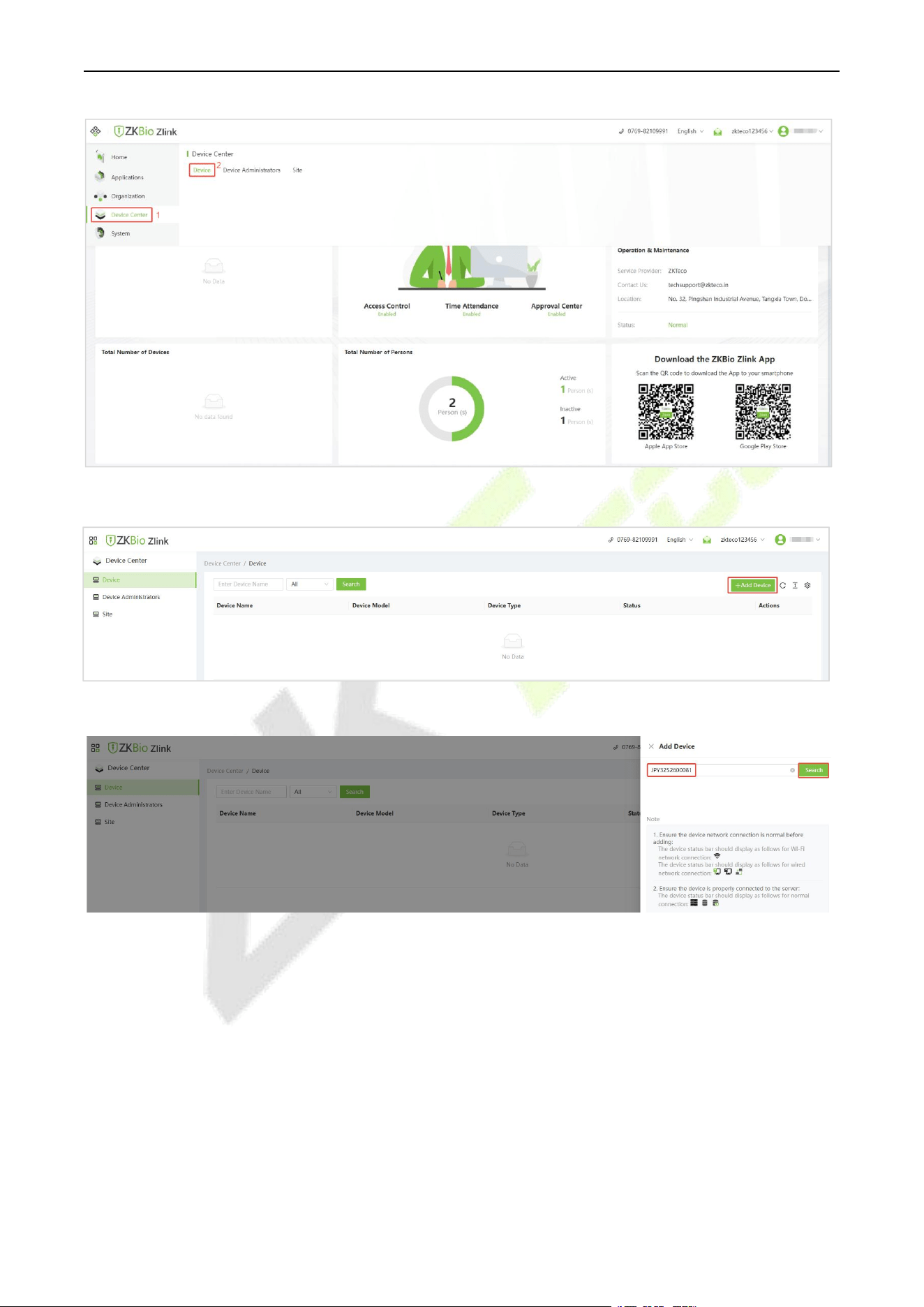
F34 User Manual
P a g e | 120 Copyright © 2026 ZKTECO CO., LTD. All rights reserved.
2. Then click [Add Device] to enter the Add Device interface.
3. Enter the Serial Number and click [Search].
4. Then enter the device name and specify the device to a site. Select Site from the drop- down menu.
Click [Save] to complete the addition.
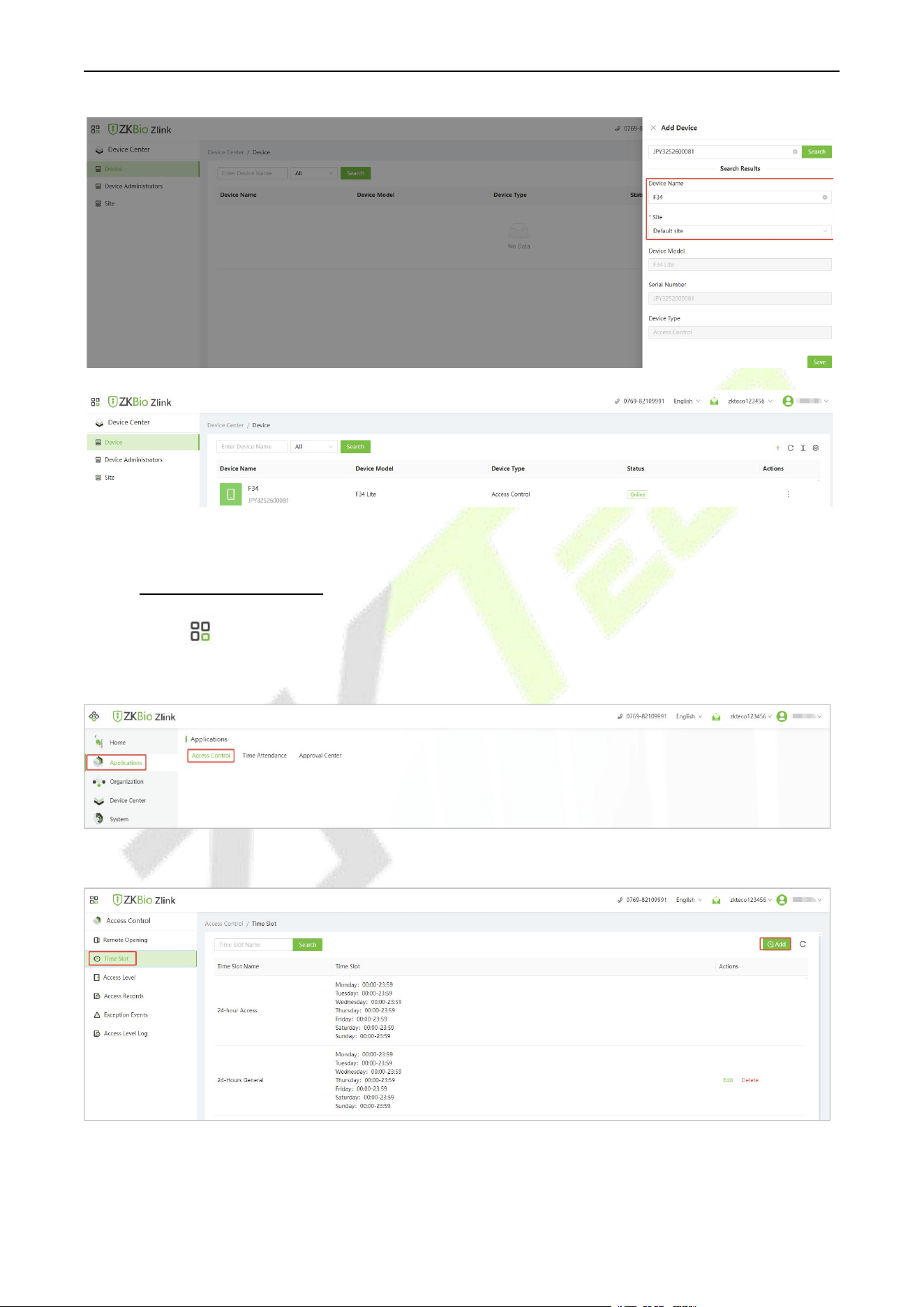
F34 User Manual
P a g e | 121 Copyright © 2026 ZKTECO CO., LTD. All rights reserved.
Note: Wait a moment for the device status to change from “Offline” to “Online”.
21.3 Set Access Levels
1. Click the icon on the top left corner, and click [Applications] > [Access Control] to enter the
access control settings interface.
2. Click [Time Slot] > [Add] to add a time slot.
3. Set the name and time slot, and click [Save]. Then the time lot will be displayed in the list. (Note:
There is a default timeslot named 24-hour Access in the system.)
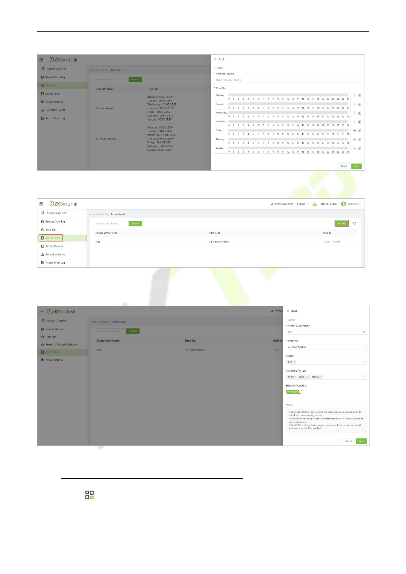
F34 User Manual
P a g e | 122 Copyright © 2026 ZKTECO CO., LTD. All rights reserved.
4. Click [Access Level] > [Add] to add an access level.
5. Set the access level name, select the time slot, device, and persons, then click Save to synchronize the
access level to the device.
21.4 Register Verification Mode on the Web
1. Click the icon on the top left corner, and click [Organization] > [Credential] to enter the
credentials setting interface.
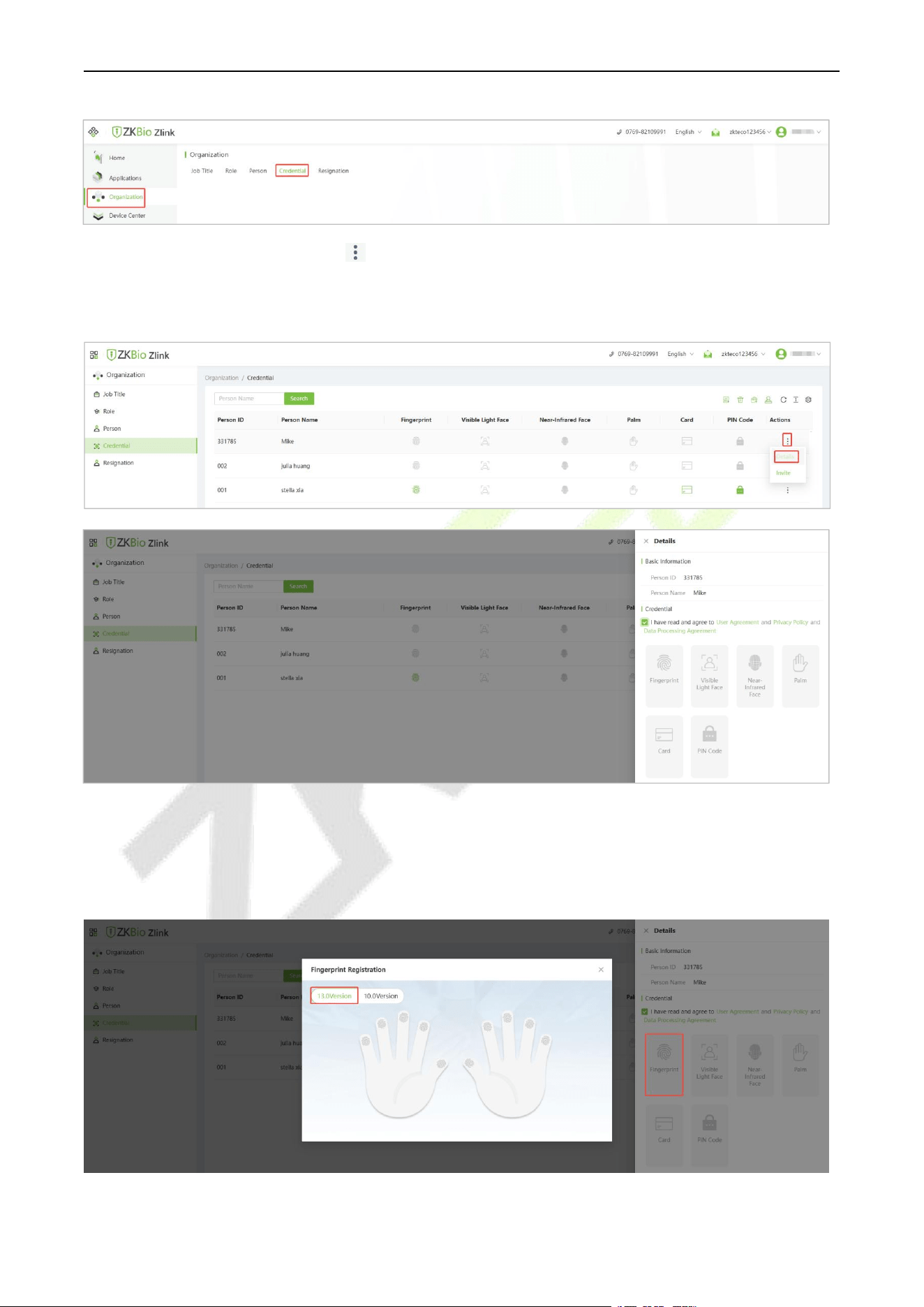
F34 User Manual
P a g e | 123 Copyright © 2026 ZKTECO CO., LTD. All rights reserved.
2. Select the person and click the icon > Details, check “I have read and agree to User Agreement
and Privacy Policy and Data Processing Agreement” and click Fingerprint/Card/PIN Code to
remotely register the personnel biometric verification mode.
Register Fingerprint
1. Click Fingerprint in the Details page. Click 13.0Version or 10.0Version (it depends on the fingerprint
algorithm that set in System > Fingerprint). Choose the hand and finger to be enrolled in the pop-up
prompt window.

F34 User Manual
P a g e | 124 Copyright © 2026 ZKTECO CO., LTD. All rights reserved.
2. Select the registration device, the device will display the fingerprint registration screen. According to
the prompts, place your finger on the fingerprint sensor and press 3 times. When the interface
prompts “Enrolled Successfully”, it means the fingerprint registration is successful.
3. And you can repeat the above operation to register other fingers.
Register Card
1. Click Card in the Details page. You can select Register on Device or Manually Enter Card Number. If
you want to register on device, then click Register on Device.
2. Select the registration device, the device will display the Enroll Card Number interface. Place the card
in the swipe area, when the display shows green √, it means the card is successfully registered.
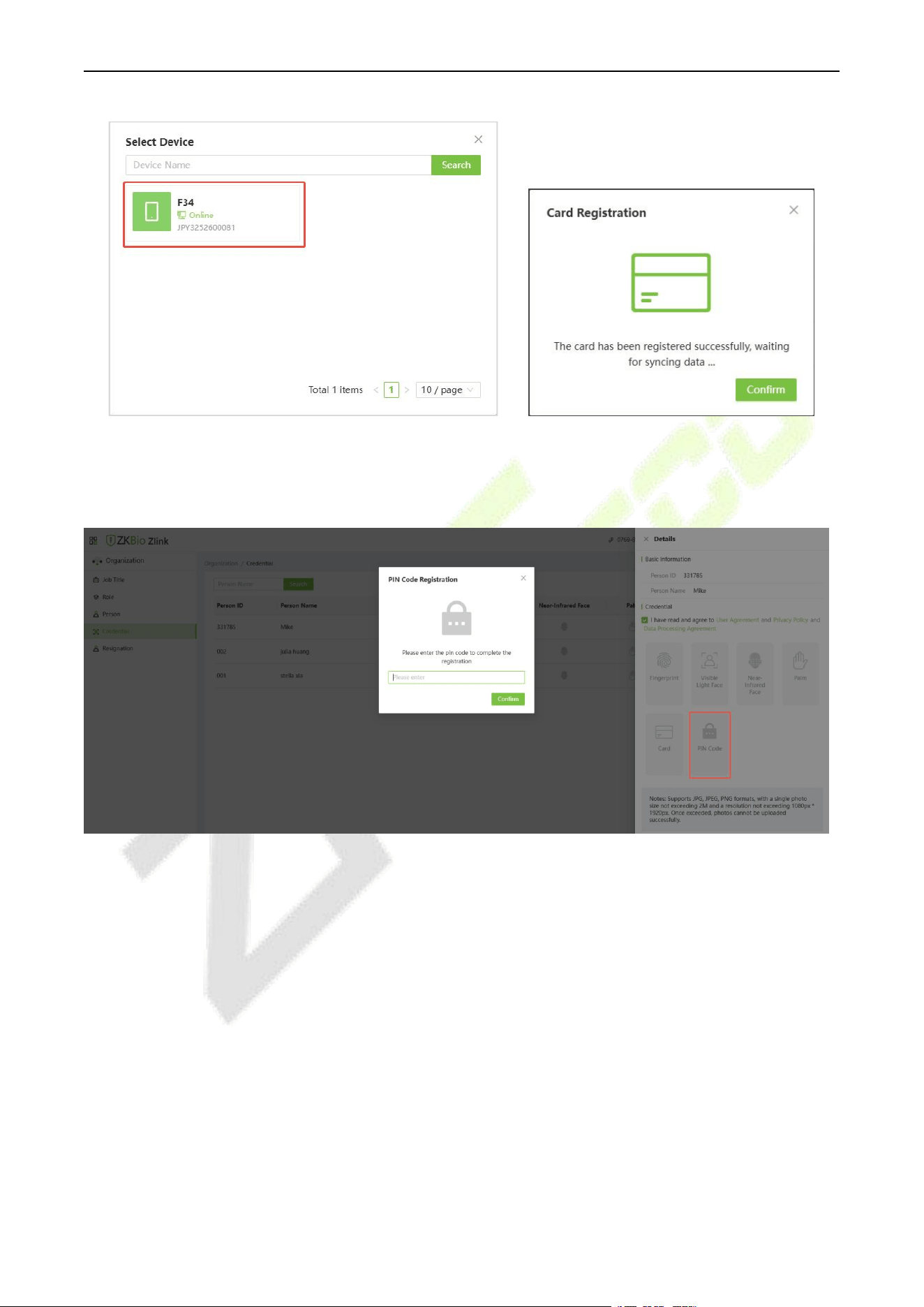
F34 User Manual
P a g e | 125 Copyright © 2026 ZKTECO CO., LTD. All rights reserved.
Register Password
Click PIN Code in the Details page. Set the password in the pop-up prompt window, and then click
[Confirm].
For more details, please refer to the ZKBio Zlink User Manual.
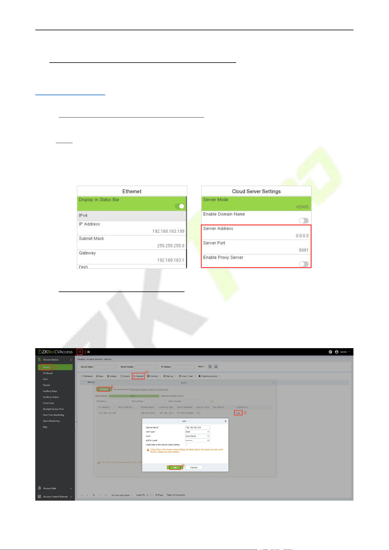
F34 User Manual
P a g e | 126 Copyright © 2026 ZKTECO CO., LTD. All rights reserved.
22 Connect to ZKBio CVAccess Software
Change the device type as A&C PUSH, then the device can be connected to ZKBio CVAccess, please refer to
9.4 Device Type Setting.
22.1 Set the Communication Address
1. Press M/OK and enter COMM. > Ethernet to set the IP address and gateway of the device.
(Note: The IP address should be able to communicate with the ZKBio CVAccess server)
2. Press M/OK and enter COMM. > Cloud Server Setting to set the server address and server port.
Server address: Set the IP address as of ZKBio CVAccess server.
Server port: Set the server port as of ZKBio CVAccess.
22.2 Add Device on the Software
Add the device by searching. The process is as follows:
1. Click Access > Device > Search > Search, to open the Search interface in the software.
2. Click Search, and it will prompt [Searching……].
3. After searching, the list and total number of access controllers will be displayed.
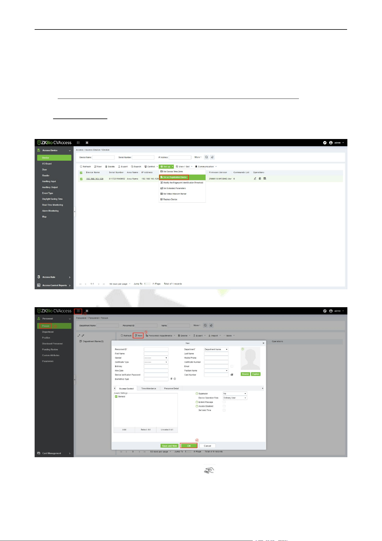
F34 User Manual
P a g e | 127 Copyright © 2026 ZKTECO CO., LTD. All rights reserved.
4. Click [Add] in operation column, a new window will pop-up. Select Icon type, Area, and Add to Level
from each dropdown and click [OK] to add the device.
5. After the addition is successful, the device will be displayed in the device list.
22.3 Add Personnel on the Software and Online Fingerprint
Registration
1. In the device list, select the device and click Set up > Set as Registration Device.
2. Click Personnel > Person > New:
3. Fill in all the required fields of the user and click to enter the online fingerprint registration
interface.
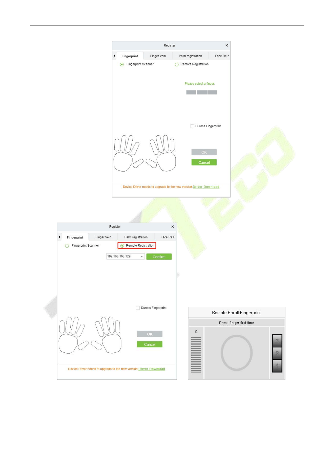
F34 User Manual
P a g e | 128 Copyright © 2026 ZKTECO CO., LTD. All rights reserved.
4. Click Driver Download to install the driver first.
5. Select Remote Registration, then select the IP address of the device and click Confirm.
6. Select the finger you want to register and press your finger on the fingerprint sensor of the device
three times. If the fingerprint is successfully registered, the device will prompt "Enrolled successfully".
7. If you want to register a duress fingerprint, you can click Duress Fingerprint before registering the
fingerprint.
Duress fingerprint: In any case, a duress alarm is generated when a fingerprint matches a

F34 User Manual
P a g e | 129 Copyright © 2026 ZKTECO CO., LTD. All rights reserved.
duress fingerprint.
8. Click OK to save the user.
9. Click Access > Device > Control > Synchronize All Data to Devices to synchronize all the data to
the device including the new users.
22.4 Mobile Credential★
After downloading and installing the ZKBio Zexus Mobile App, the user needs to set the Server before
login. The steps are given below:
1. In ZKBio CVAccess, click System > System Management > Parameters, set Enable QR Code to
‘’Yes’’, and select the Qrcode Type as Dynamic, the valid time of the QR code can be set.
2. Click Personnel > Personnel > Person, select the personnel and click More > Enable APP Login.
3. Open the App on the Smartphone. On the login screen, select the role-Personnel, enter the account
information, and click Login.
Organization Name: Scan the organization code you get before. (Enter System > System
Management >Cloud Setting >APP enterprise QR Code)
Account & Password: The personnel ID & password (default: 123456).
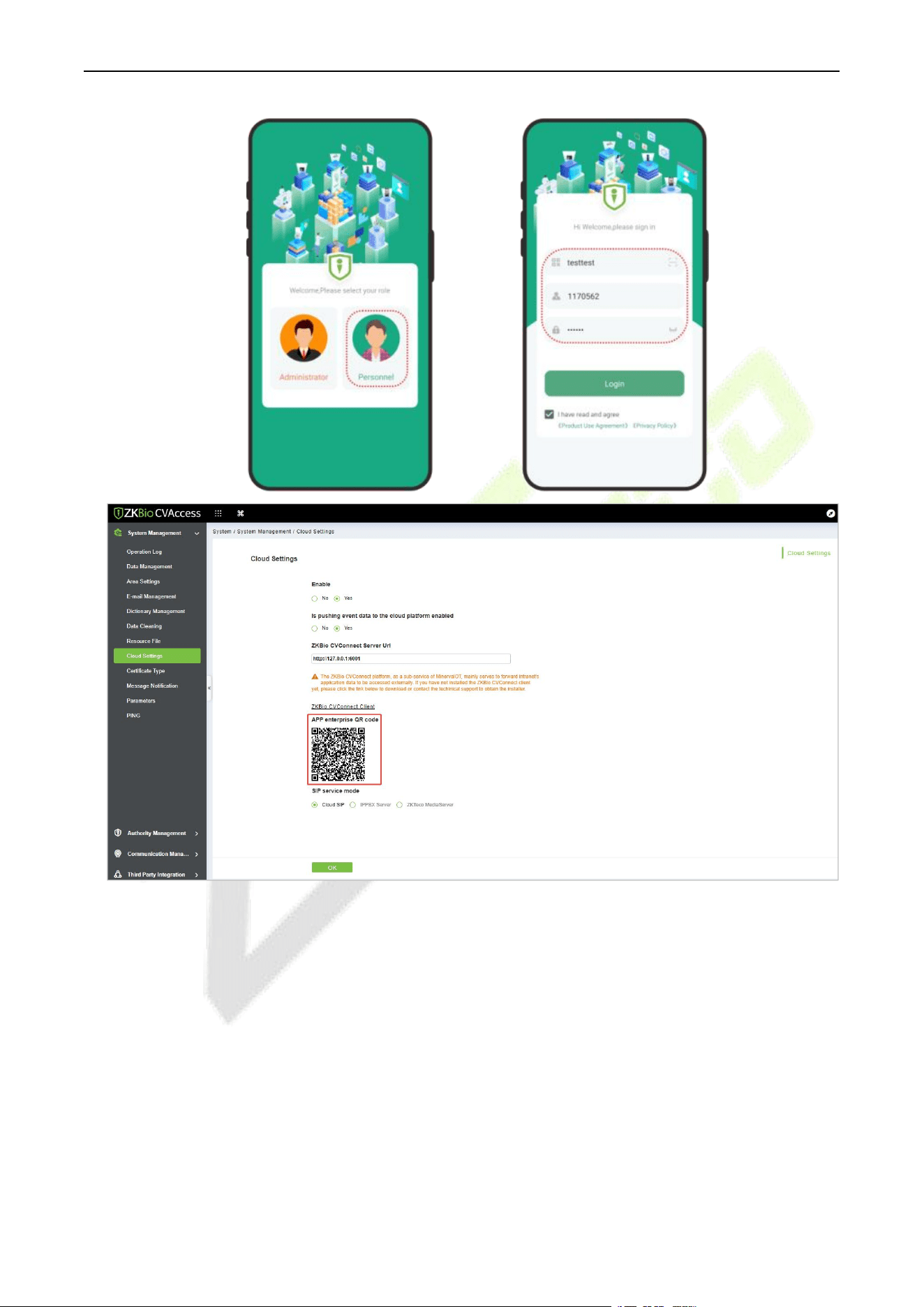
F34 User Manual
P a g e | 130 Copyright © 2026 ZKTECO CO., LTD. All rights reserved.
4. Click Application Center > Mobile Credential on the App, and a QR code will appear, which
includes employee ID and card number information.
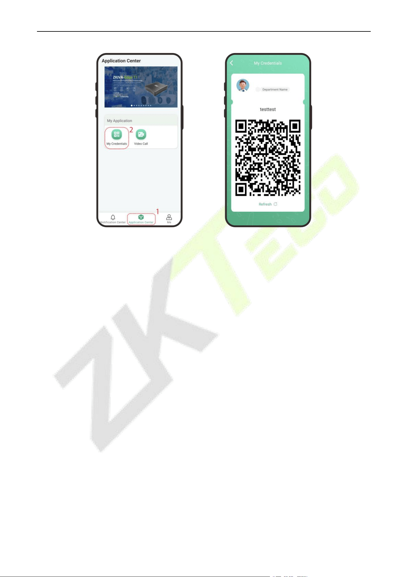
F34 User Manual
P a g e | 131 Copyright © 2026 ZKTECO CO., LTD. All rights reserved.
5. The QR code can replace a physical card on a specific device to achieve contactless authentication to
open the door.
6. The QR code refreshes automatically for every 30s and supports manual refresh.
Note: For other specific operations, please refer to ZKBio CVAccess User Manual.
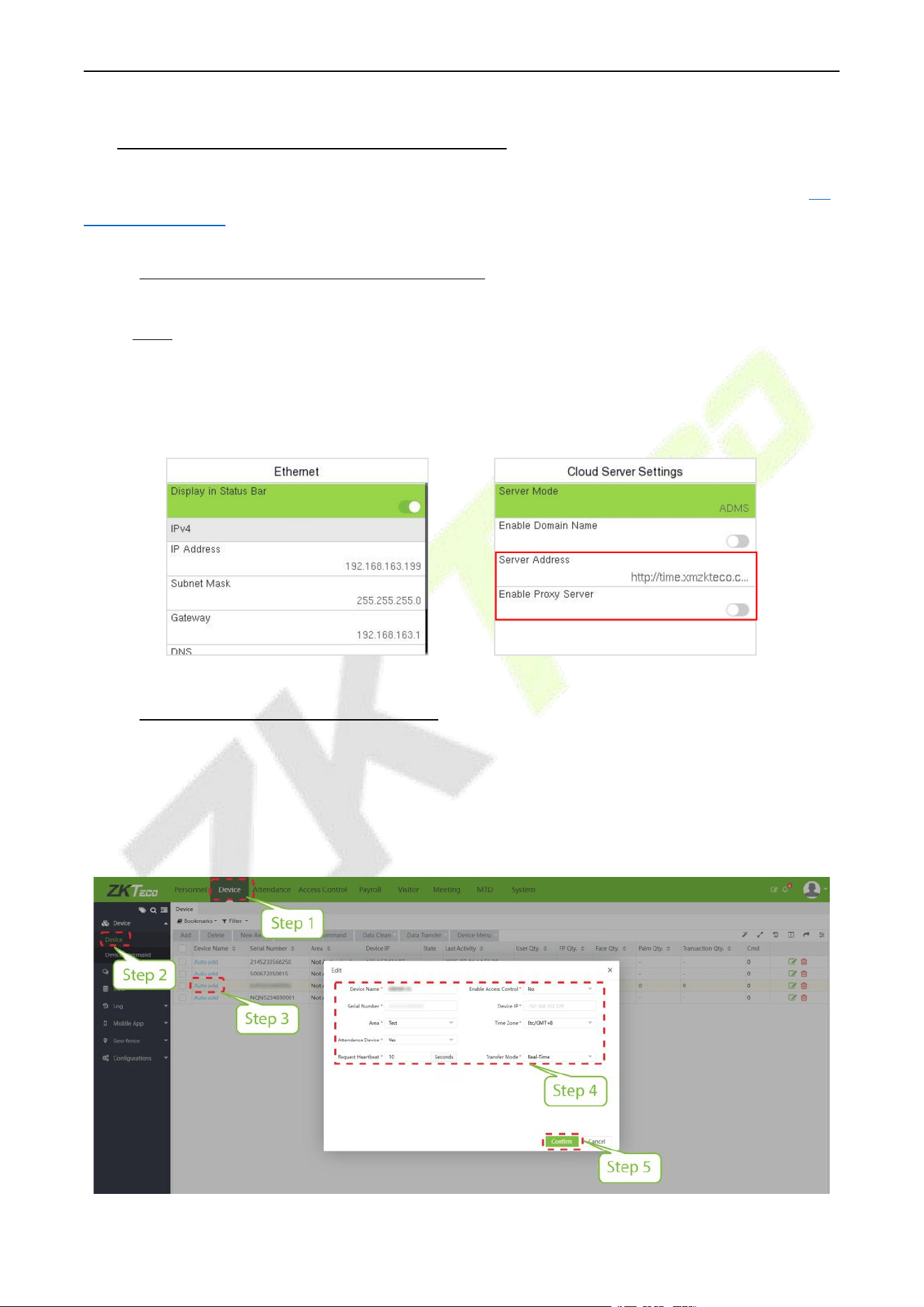
F34 User Manual
P a g e | 132 Copyright © 2026 ZKTECO CO., LTD. All rights reserved.
23 Connect to ZKBio Time Software
Change the device type as T&A PUSH, then the device can be connected to ZKBio Time, please refer to 9.4
Device Type Setting.
23.1 Set the Communication Address
1. Press M/OK and enter COMM. > Ethernet to set the IP address and gateway of the device.
(Note: The IP address should be able to communicate with the ZKBio Time server)
2. Press M/OK and enter COMM. > Cloud Server Setting to set the server address and server port.
Server address: Set the IP address as of ZKBio Time server.
Server port: Set the server port as of ZKBio Time server.
Or you can choose to enable Domain Name and set the server address.
23.2 Add Device on the Software
After setting on the device, the device will be automatically added to the software. Open the ZKBio Time
software then select [Device Module] > [Device] > [Device], click the device in the list, change the Device
Name and Area.
Note: The devices added automatically must be assigned to custom areas to communicate with the
software.
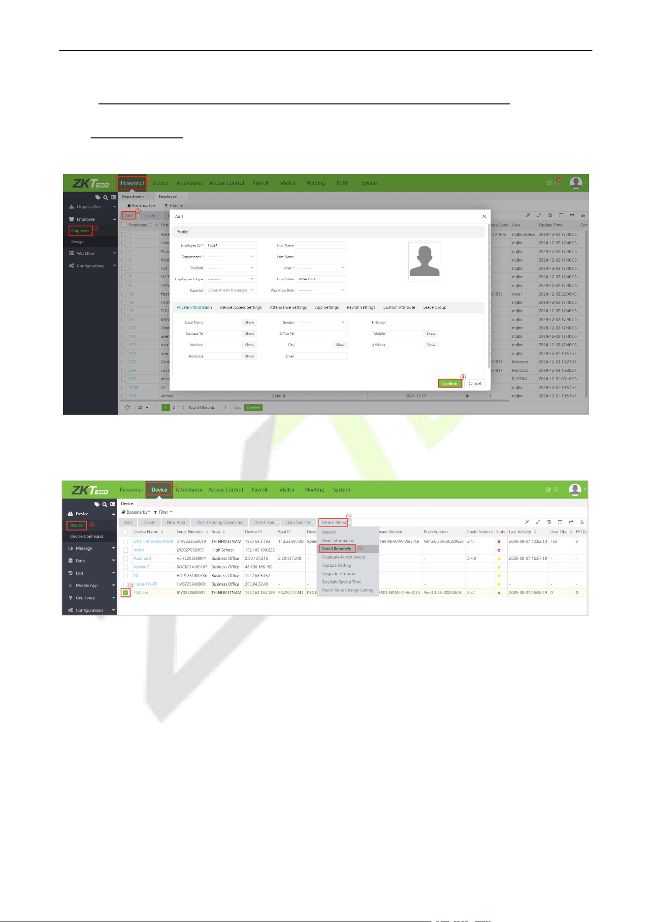
F34 User Manual
P a g e | 133 Copyright © 2026 ZKTECO CO., LTD. All rights reserved.
23.3 Add Personnel on the Software and Online Fingerprint
Registration
1. Click Personnel > Employee > Add:
2. Fill in all the required fields and click [Confirm] to register a new user.
3. Click Device > Device, select the device and click Device Menu > Enroll Remotely.
4. Enter the Employee ID and select the finger you want to register and press your finger on the
fingerprint sensor of the device three times. If the fingerprint is successfully registered, the device
will prompt "Enrolled successfully".
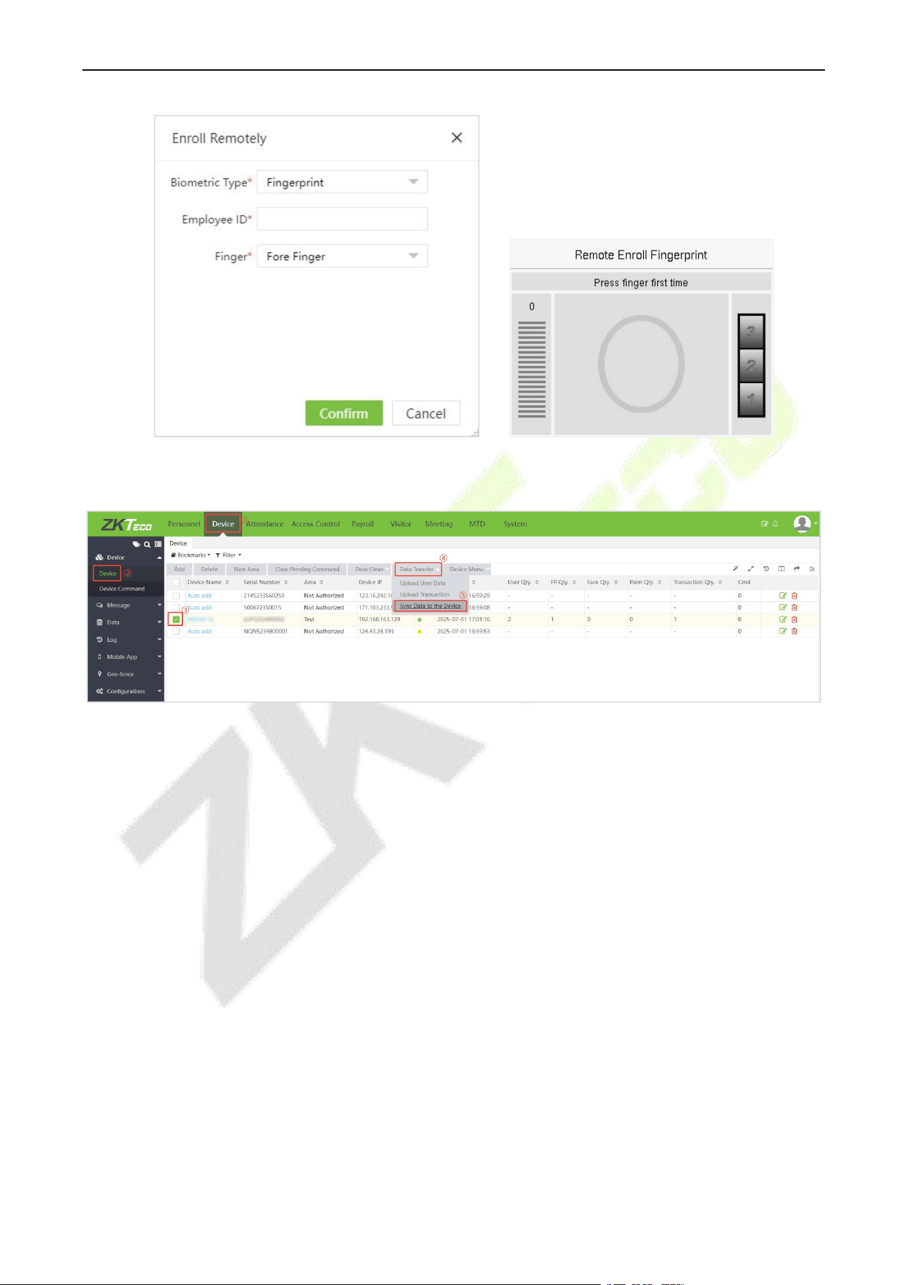
F34 User Manual
P a g e | 134 Copyright © 2026 ZKTECO CO., LTD. All rights reserved.
5. Select the device in the list, click Data Transfer > Sync Data to the Device to synchronize all the
data to the device including the new users.
Note: For other specific operations, please refer the ZKBio Time User Manual.
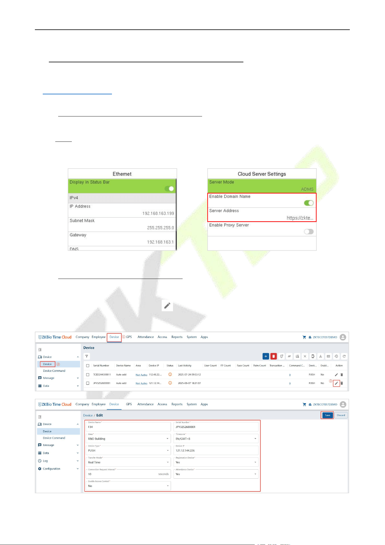
F34 User Manual
P a g e | 135 Copyright © 2026 ZKTECO CO., LTD. All rights reserved.
24 Connect to ZKBio Time Cloud Software
Change the device type as T&A PUSH, then the device can be connected to ZKBio Time Cloud, please refer
to 9.4 Device Type Setting.
24.1 Set the Communication Address
1. Press M/OK and enter COMM. > Ethernet to set the IP address and gateway of the device.
(Note: The IP address should be able to communicate with the ZKBio Time Cloud)
2. Press M/OK and enter COMM. > Cloud Server Setting to enable Domain Name and enter the
correct domain name.
24.2 Add Device on the Software
After setting on the device, the device will be automatically added to the software. Open ZKBio Time
Cloud software, click Device > Device > Edit icon to enter the Device Edit interface. Change the
Device Name and Area, then it can communicate with the software.
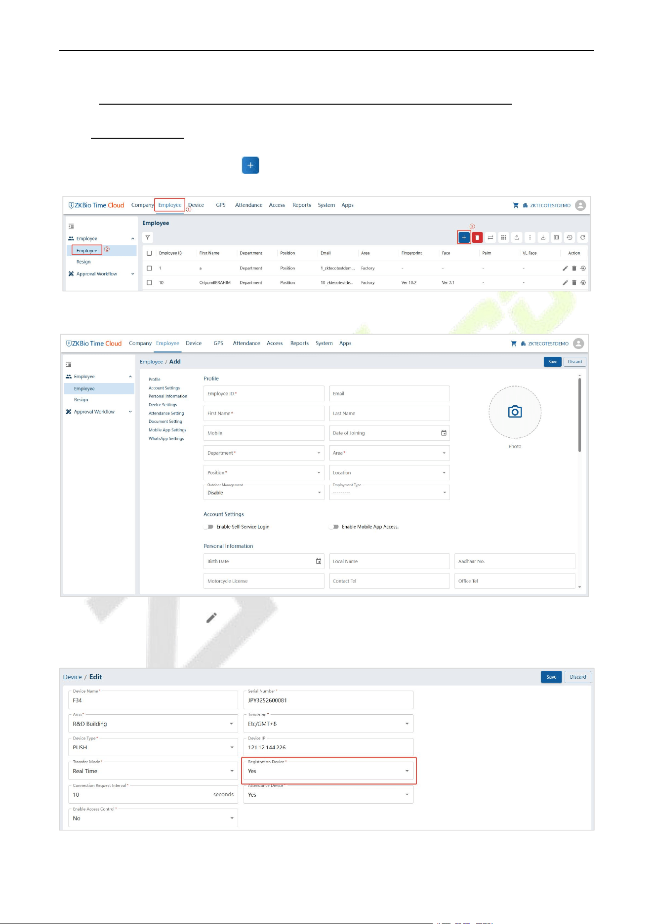
F34 User Manual
P a g e | 136 Copyright © 2026 ZKTECO CO., LTD. All rights reserved.
24.3 Add Personnel on the Software and Online Fingerprint
Registration
1. Click Employee > Employee > Add icon to enter the Employee Add interface.
2. Fill in all the required fields and click Save to register a new user.
3. Click Device > Device > Edit icon to enter the Device Edit interface, set the Registration Device as
Yes and click Save.
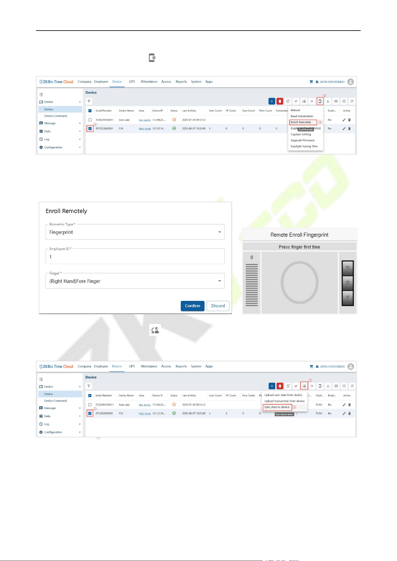
F34 User Manual
P a g e | 137 Copyright © 2026 ZKTECO CO., LTD. All rights reserved.
4. Select the device in the list, click icon > Enroll Remotely.
5. Enter the Employee ID and select the finger you want to register and press your finger on the
fingerprint sensor of the device three times. If the fingerprint is successfully registered, the device will
display "Enrolled successfully".
6. Select the device in the list, click icon > Sync Data to Device to synchronize all the data into the
device including the new users.
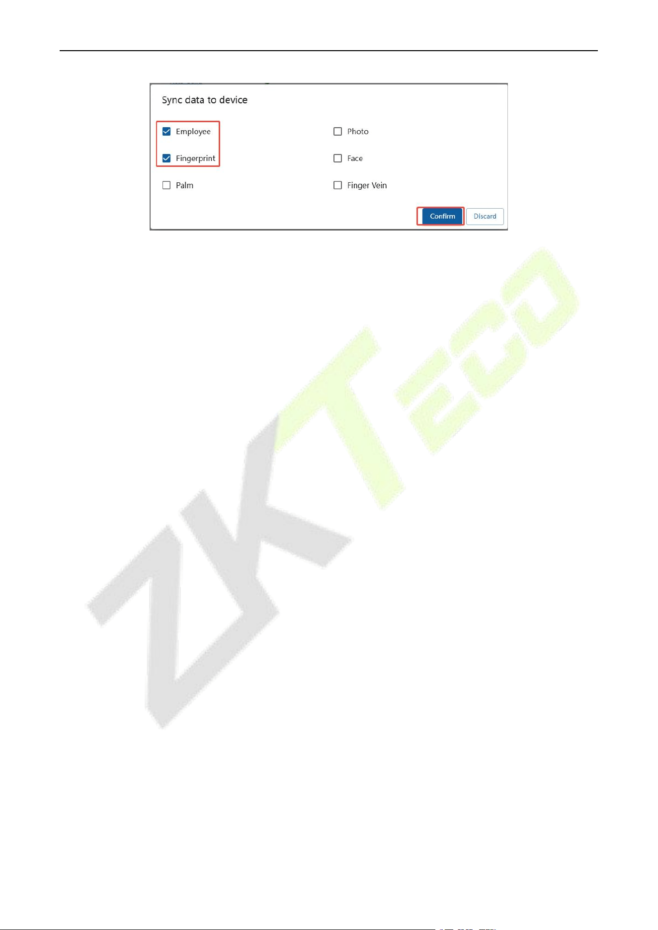
F34 User Manual
P a g e | 138 Copyright © 2026 ZKTECO CO., LTD. All rights reserved.
Note: For other specific operations, please refer the ZKBio Time Cloud User Manual.
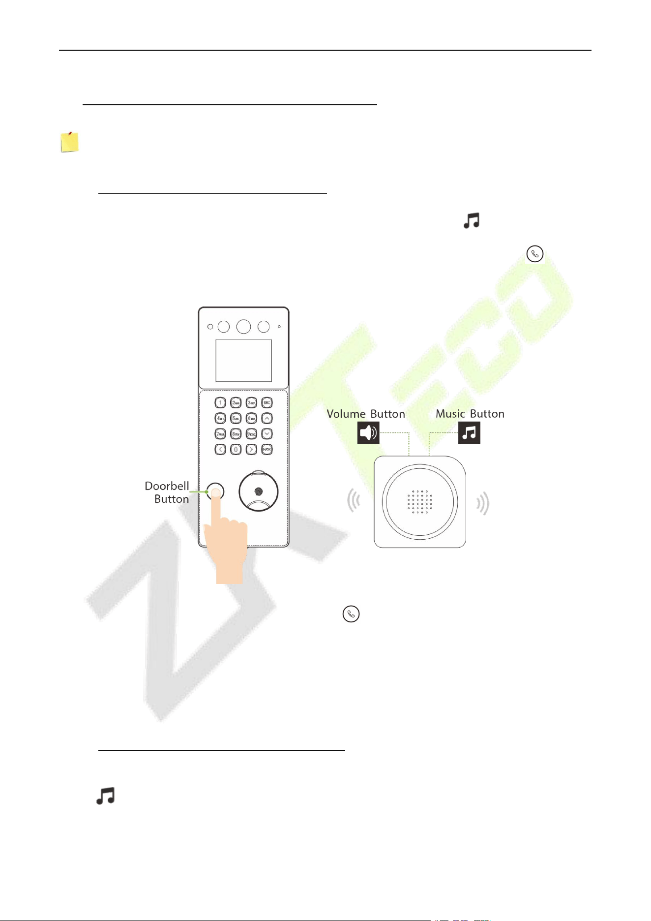
F34 User Manual
P a g e | 139 Copyright © 2026 ZKTECO CO., LTD. All rights reserved.
25 Connecting to Wireless Doorbell★
Note: This function needs to be used with the wireless doorbell.
25.1 Connect the Wireless Doorbell
1. First, power on the wireless doorbell. Then, press and hold the music button for 1.5 seconds until
the indicator flashes to indicate it's in pairing mode. After that, press the doorbell button on the
device, if the wireless doorbell rings and the indicator flashes, it means the pairing was successful.
2. After a successful pairing, press the doorbell button on the device will ring the wireless doorbell.
Note:
1) Each device only supports one wireless doorbell.
2) Wireless doorbell needs to be purchased by the customers themselves.
25.2 Unbinding the Wireless Doorbell
Power off the wireless doorbell first, then re-installing the batteries while pressing and holding the music
button until the indicator is on, indicating that the unbinding is successful.
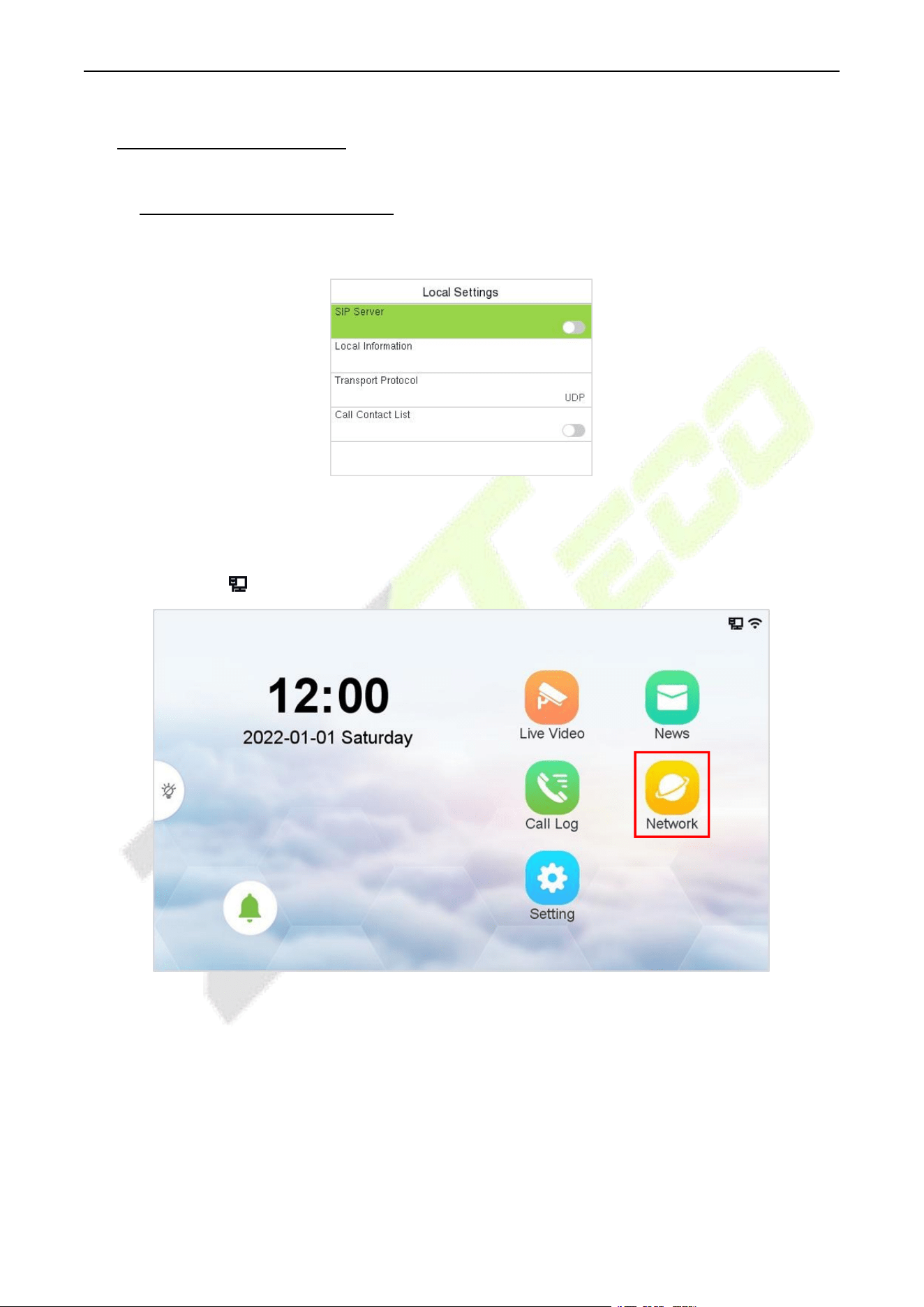
F34 User Manual
P a g e | 140 Copyright © 2026 ZKTECO CO., LTD. All rights reserved.
26 SIP Video Intercom
26.1 Local Area Network Use
In this mode, please make sure that the SIP Server of the device is disabled.
This function needs to be used with the indoor monitor VT07-B01.
On the Indoor Monitor:
1. Tap Network > to enter the wired network setting interface. (Default password: 123456)
2. Set the IP Address and Gateway of the indoor monitor. (Note: The IP address should be in the same
network segment as the device.)
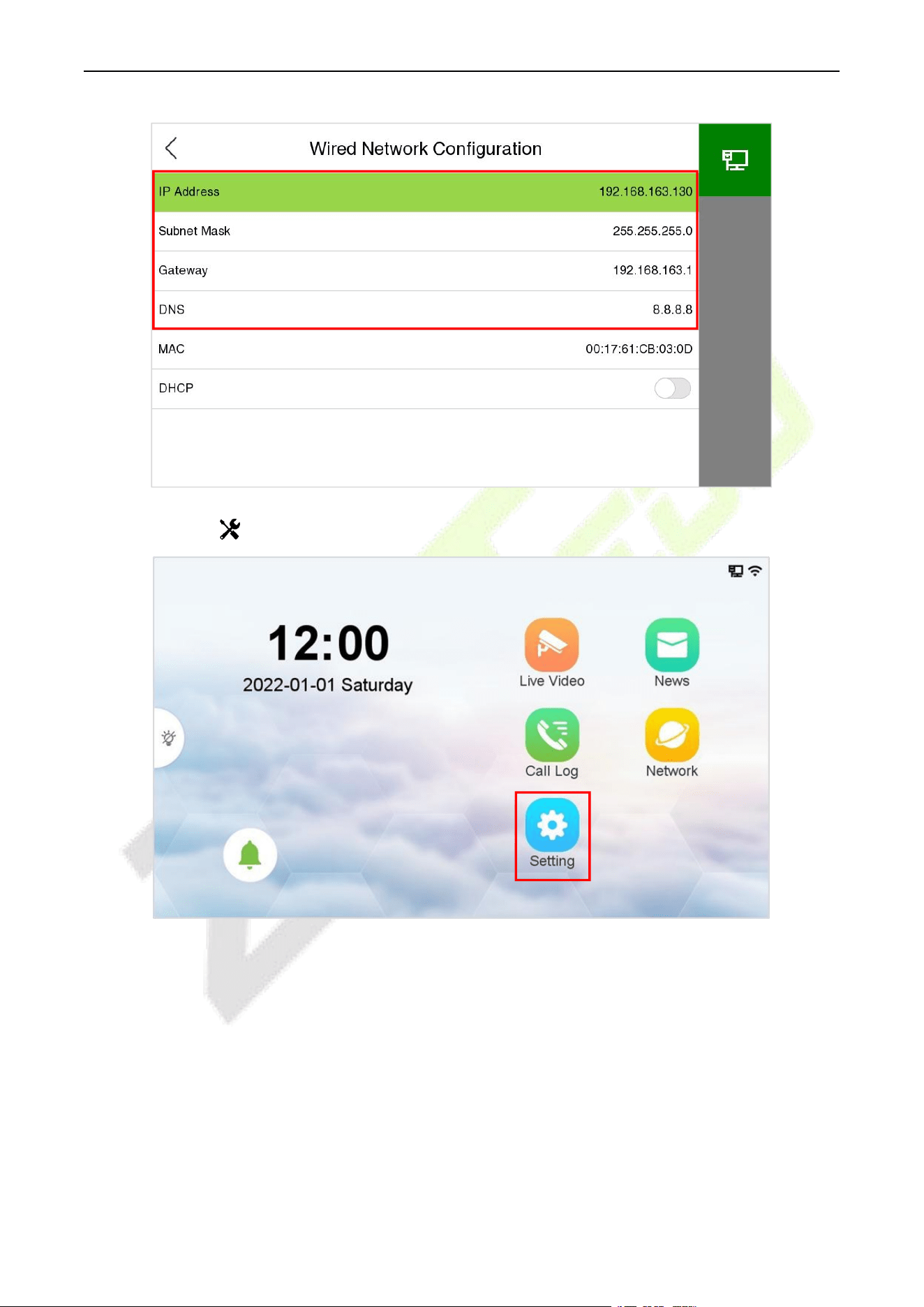
F34 User Manual
P a g e | 141 Copyright © 2026 ZKTECO CO., LTD. All rights reserved.
3. Tap Setting > Advance Setting > Device Manage > Add to add the device.
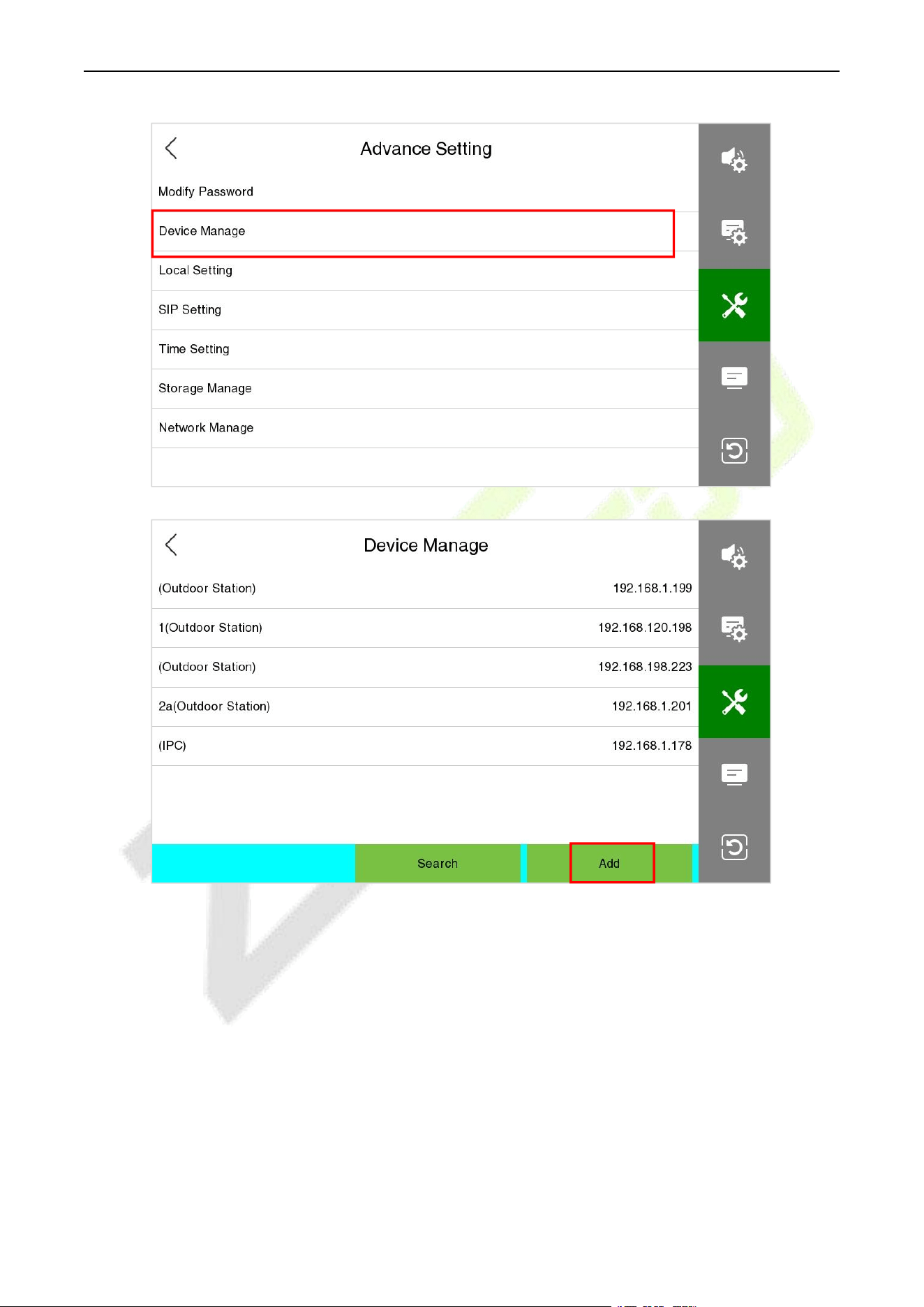
F34 User Manual
P a g e | 142 Copyright © 2026 ZKTECO CO., LTD. All rights reserved.
4. Set the related information of the device, then click Save.
Device Type: Set as Outdoor Station.
Device IP: Enter the IP address of the device.
Device Port: 8000.
User Name: admin.
Password: 123456.
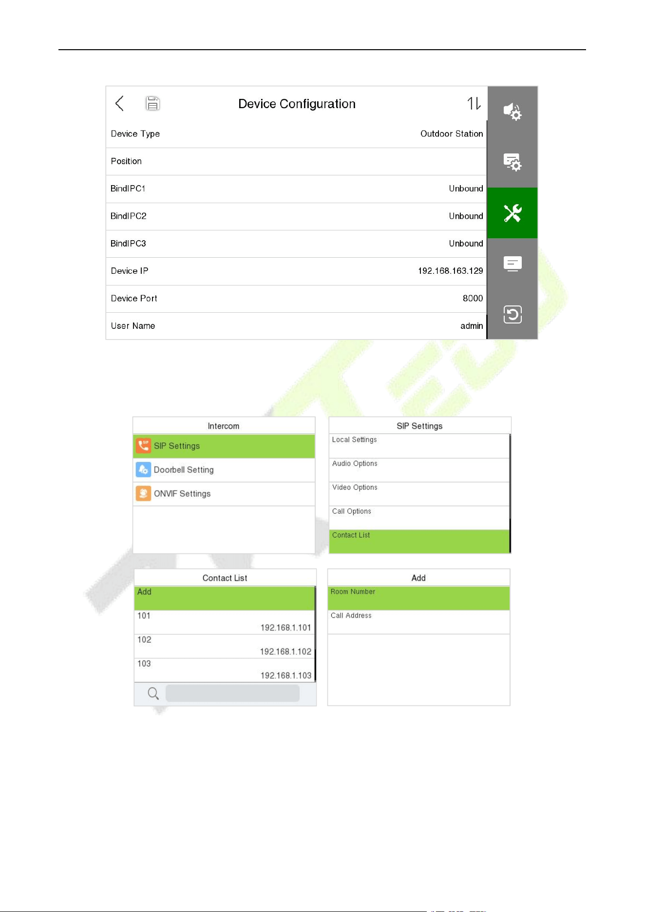
F34 User Manual
P a g e | 143 Copyright © 2026 ZKTECO CO., LTD. All rights reserved.
On the Device:
1. Press M/OK key and enter [Intercom] > [SIP Settings] > [Contact List] > [Add] to add the connected
indoor monitors.
Room Number: Customize the number of the indoor monitor.
When the device type is set as Entrance Station, the room number can be 1~ 4 digits. When the device
type is set as Fence Terminal, you need to input the block, unit and room number. For example, if the
indoor monitor is in Block 3, Unit 2, Room 2601, then input “03.02.2601”.
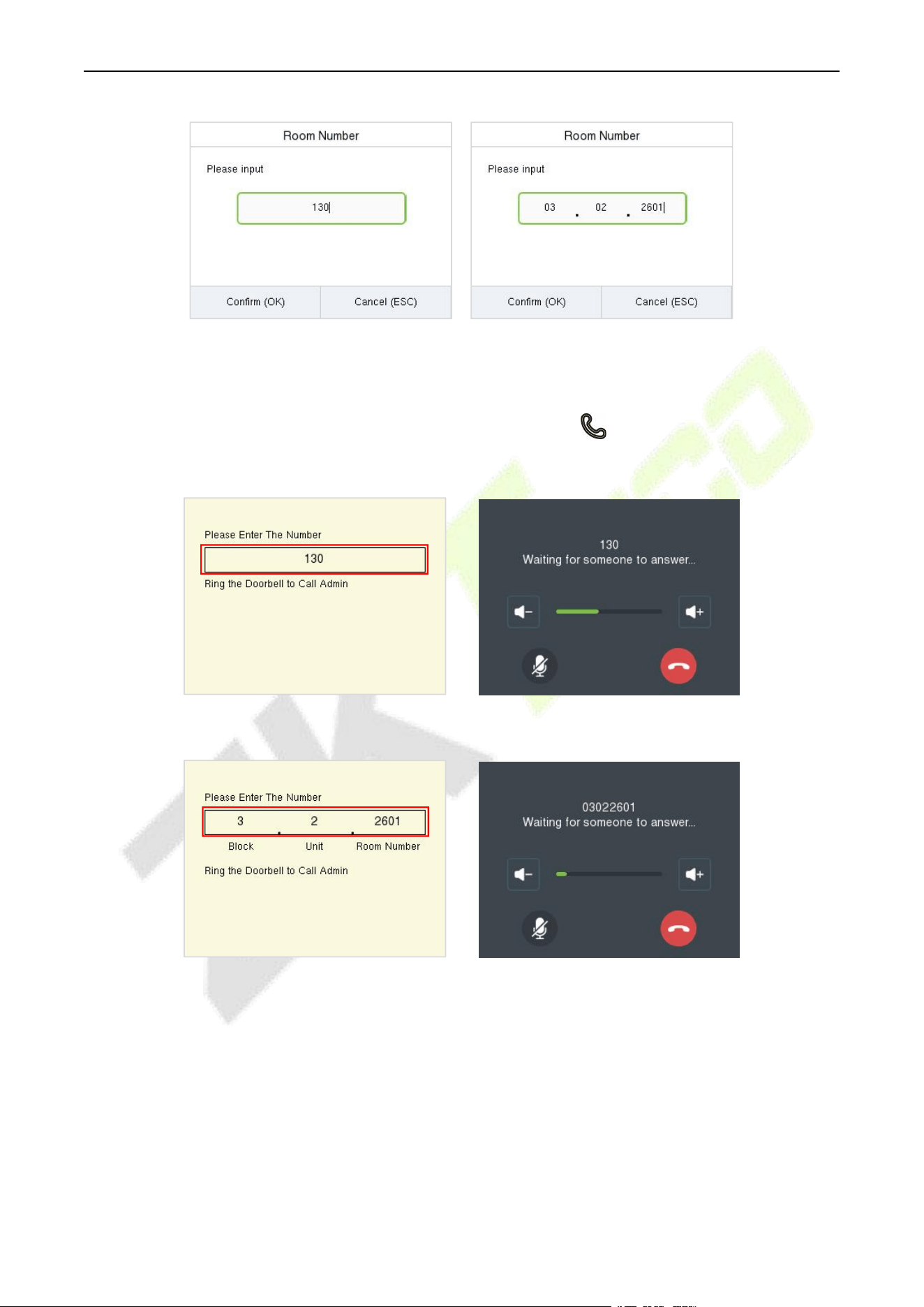
F34 User Manual
P a g e | 144 Copyright © 2026 ZKTECO CO., LTD. All rights reserved.
Entrance Station Fence Terminal
Call Address: It is the IP Address of the indoor monitor.
2. To enable the video intercom function, press the doorbell button on the device and enter the
number or IP address of the indoor monitor in the provided interface.
Entrance Station
Fence Terminal
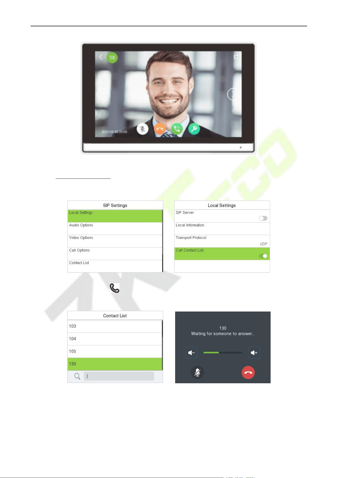
F34 User Manual
P a g e | 145 Copyright © 2026 ZKTECO CO., LTD. All rights reserved.
26.1.1 Call Contact List
1. On the SIP Settings interface, tap Local Settings > Call Contact List to enable the call contact list.
2. Press the doorbell button on the device to enter the call page, then you can press the Up key to
open the contact list, select the number of the indoor monitor you want to call.
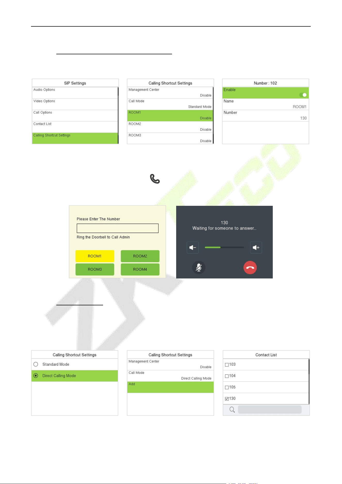
F34 User Manual
P a g e | 146 Copyright © 2026 ZKTECO CO., LTD. All rights reserved.
26.1.2 Custom the Calling Shortcut Keys
1. On the SIP Settings interface, tap Calling Shortcut Settings to enable and define the shortcut keys.
Name: Customize the name of the shortcut keys.
Number: It is the room number that set in the Contact List Menu.
2. Then you can press the doorbell button on the device and select the calling shortcut keys to call
the indoor monitor.
26.1.3 Direct Calling
1. On the SIP Settings interface, enter [Calling Shortcut Settings] > [Call Mode] > [Direct Calling
Mode] > [Add]. Select the IP address of the indoor monitors that you want to call, then the indoor
monitors will be displayed in the list.
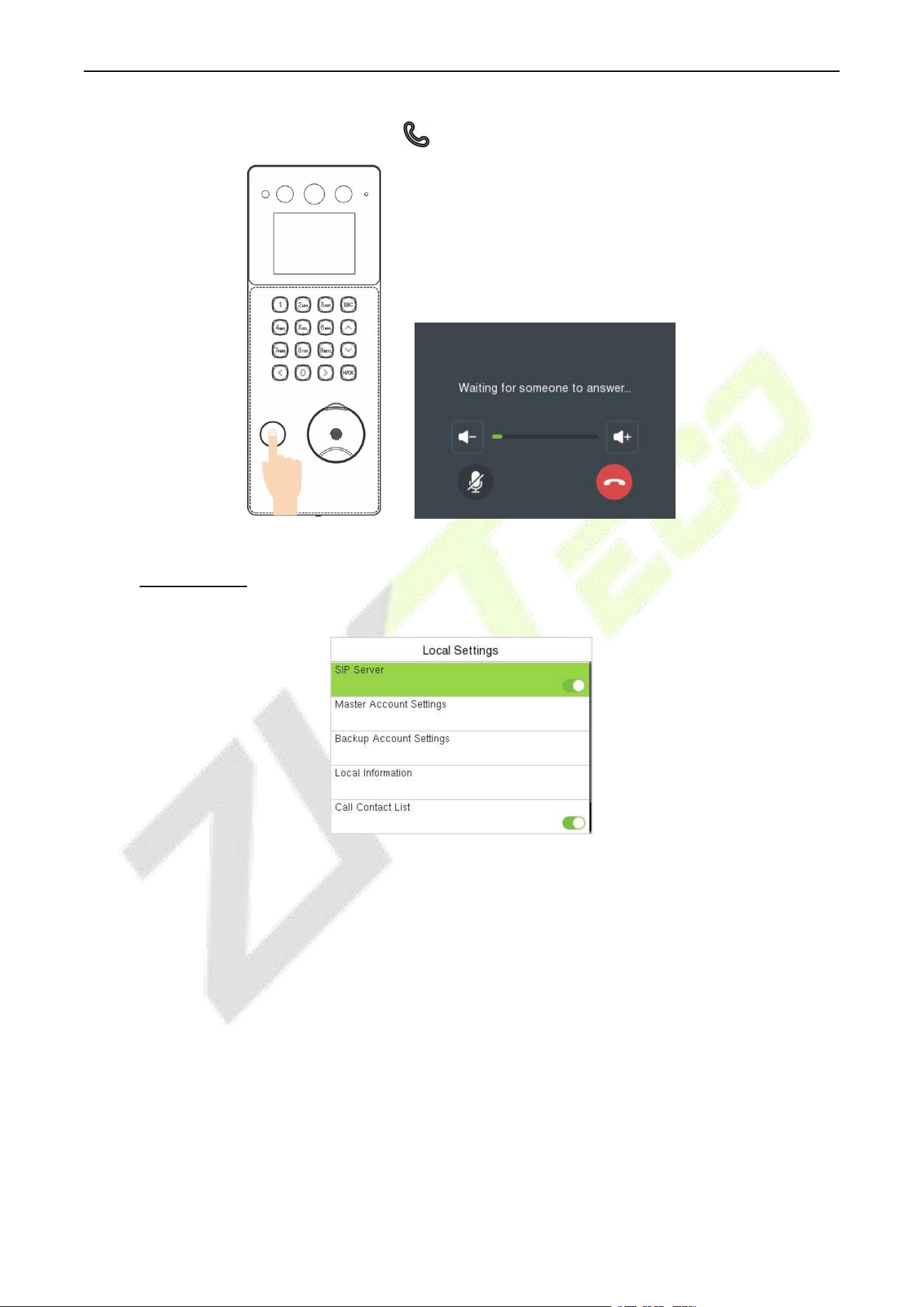
F34 User Manual
P a g e | 147 Copyright © 2026 ZKTECO CO., LTD. All rights reserved.
2. Then you can press the doorbell button on the device to call the indoor monitors directly.
26.2 SIP Server
In this mode, please make sure that the SIP Server of the device is enabled.
This function needs to be used with the ZKBio CVAccess server, ZKBio Zexus Mobile App, indoor monitor
VT07-B26L-W / VT07-B22L and PC Client BioTalk Pro.
ZKBio CVAccess supports 2 kinds of SIP server: cloud SIP and PBX server, users can choose one according
to the actual situation.
Cloud SIP mode: Users do not need to purchase additional SIP server, only need to purchase SIP
account permission.
PBX server: You need to purchase a PBX server for local deployment. You do not need to purchase an
additional SIP account.
The following text mainly introduces the Cloud SIP mode.
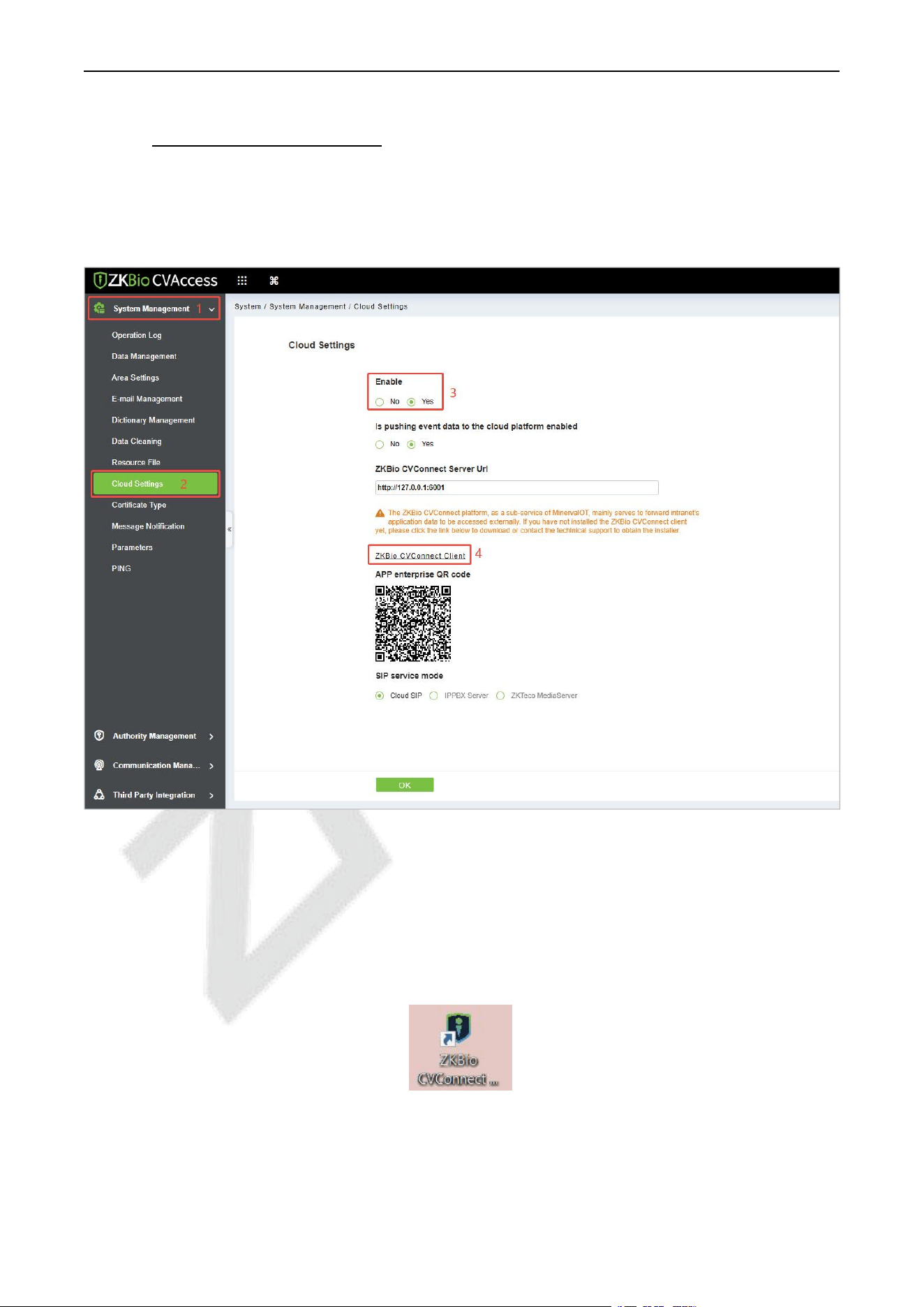
F34 User Manual
P a g e | 148 Copyright © 2026 ZKTECO CO., LTD. All rights reserved.
26.2.1 SIP Server Configuration
1. On the ZKBio CVAccess software, click System > System Management > Cloud Settings to enable
the Cloud SIP service.
2. Click ZKBio CVConnect Client to download and install it.
Note:
1) Ensure the ZKBio CVConnect client is installed if Cloud SIP is activated.
2) After cloud SIP is enabled, the device network needs to be able to connect to the external network
before it can be used.
ZKBio CVConnect Client Activation Steps
Step 1: Double-click the desktop shortcut key. Jump to browser page.
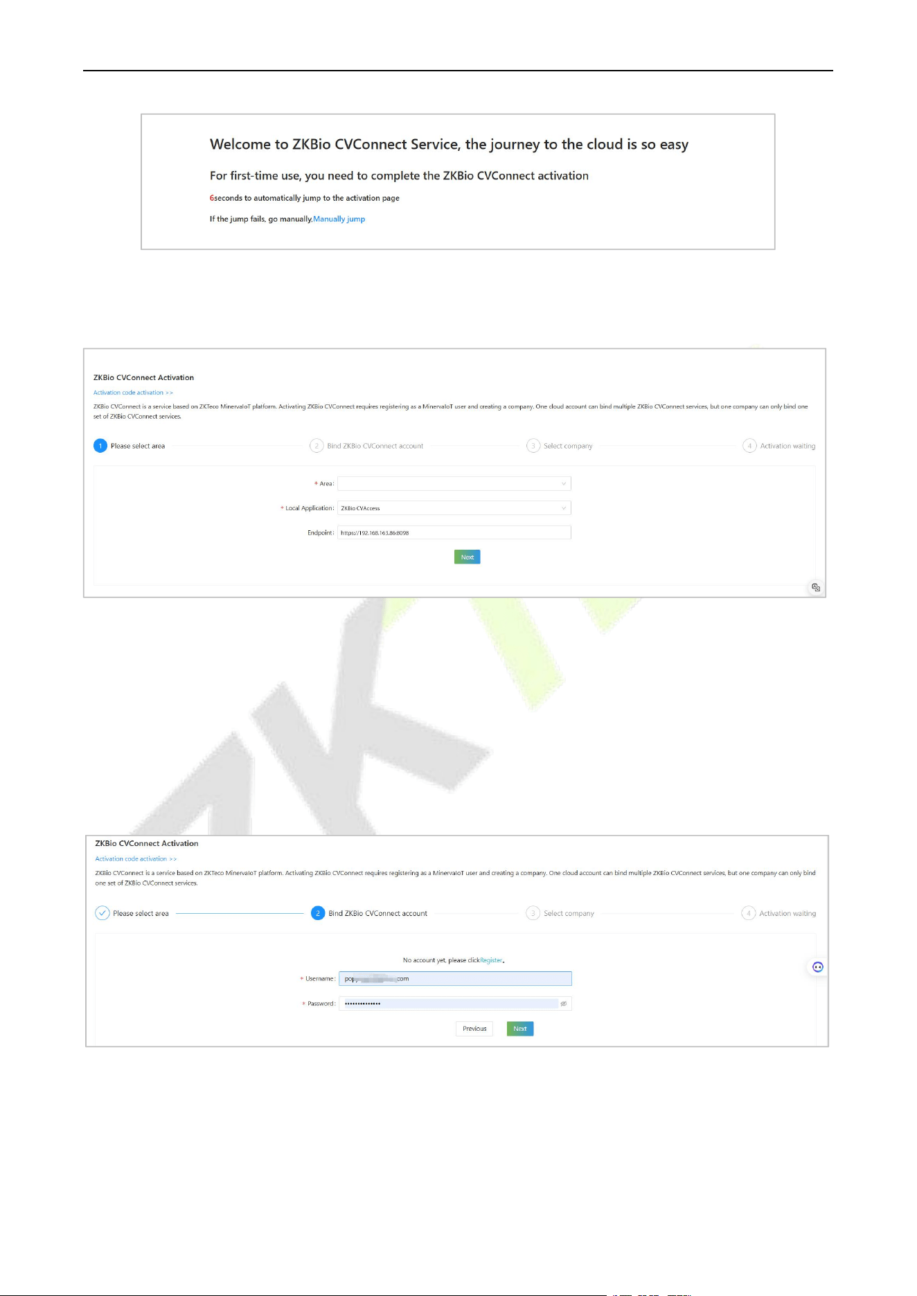
F34 User Manual
P a g e | 149 Copyright © 2026 ZKTECO CO., LTD. All rights reserved.
Step 2: Follow the steps on the page to complete activation.
1. Select Area
Area: Select the area of the cloud server, currently only China, Singapore and America are available,
other areas will be added later.
Local Application: Set as ZKBio CVAccess.
EndPoint: The server address of your local application. For example, if your local application is ZKBio
CVAccess with a server address of https://192.168.163.86:8098, enter this server address here so that
ZKBio CVConnect can correctly forward the data from your local server for access by the Mobile APP.
2. Bind ZKBio CVConnect Account
If you already have a Minerva IoT account, you can use it and log in; otherwise click on Register, then jump
to Minerva IoT registration page and register your account.
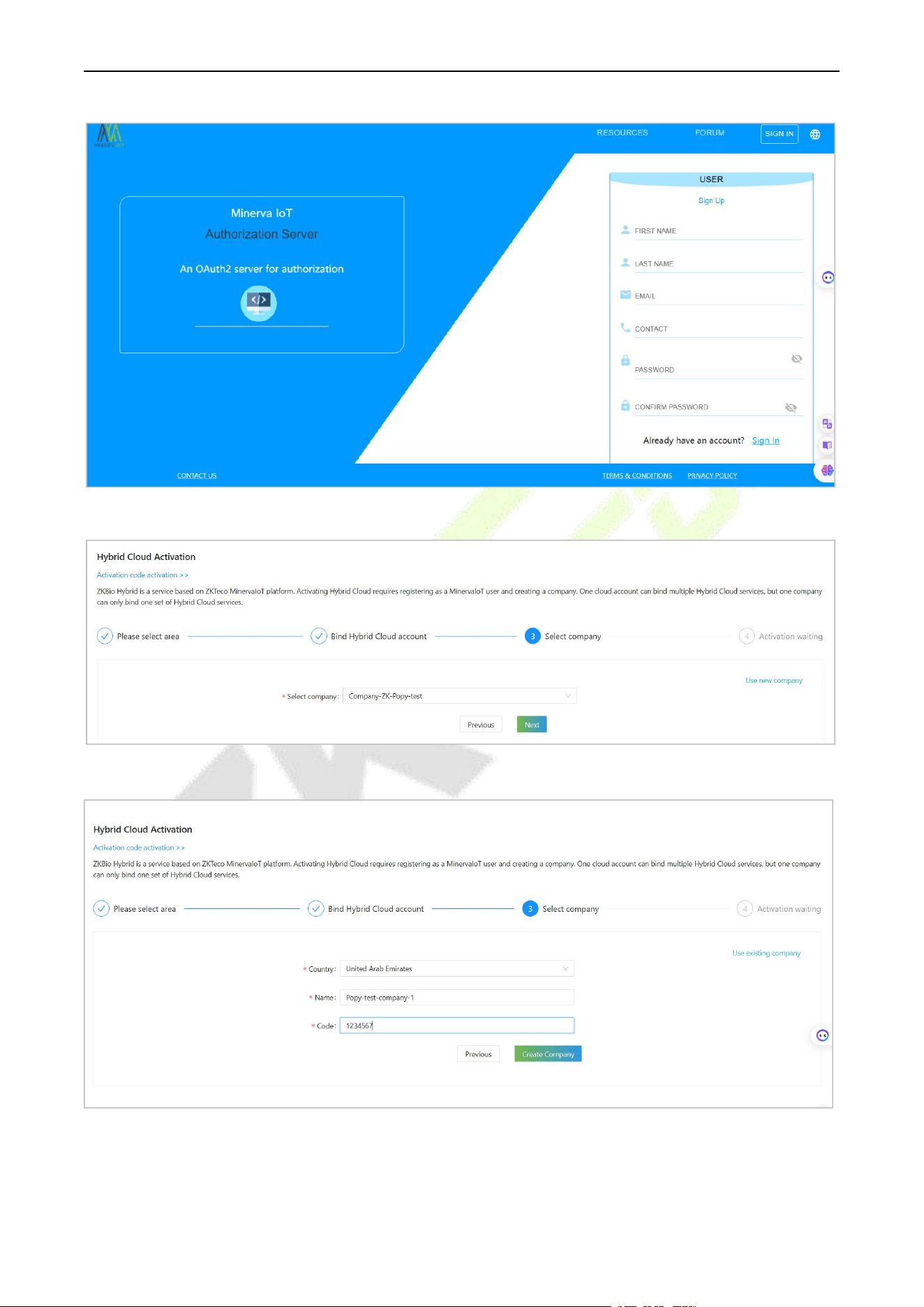
F34 User Manual
P a g e | 150 Copyright © 2026 ZKTECO CO., LTD. All rights reserved.
3. Select Company
If you don't currently have a company, you can choose to create one by clicking Use New Company.
Start Activating and wait for 1-2 minutes until the Activation completely.
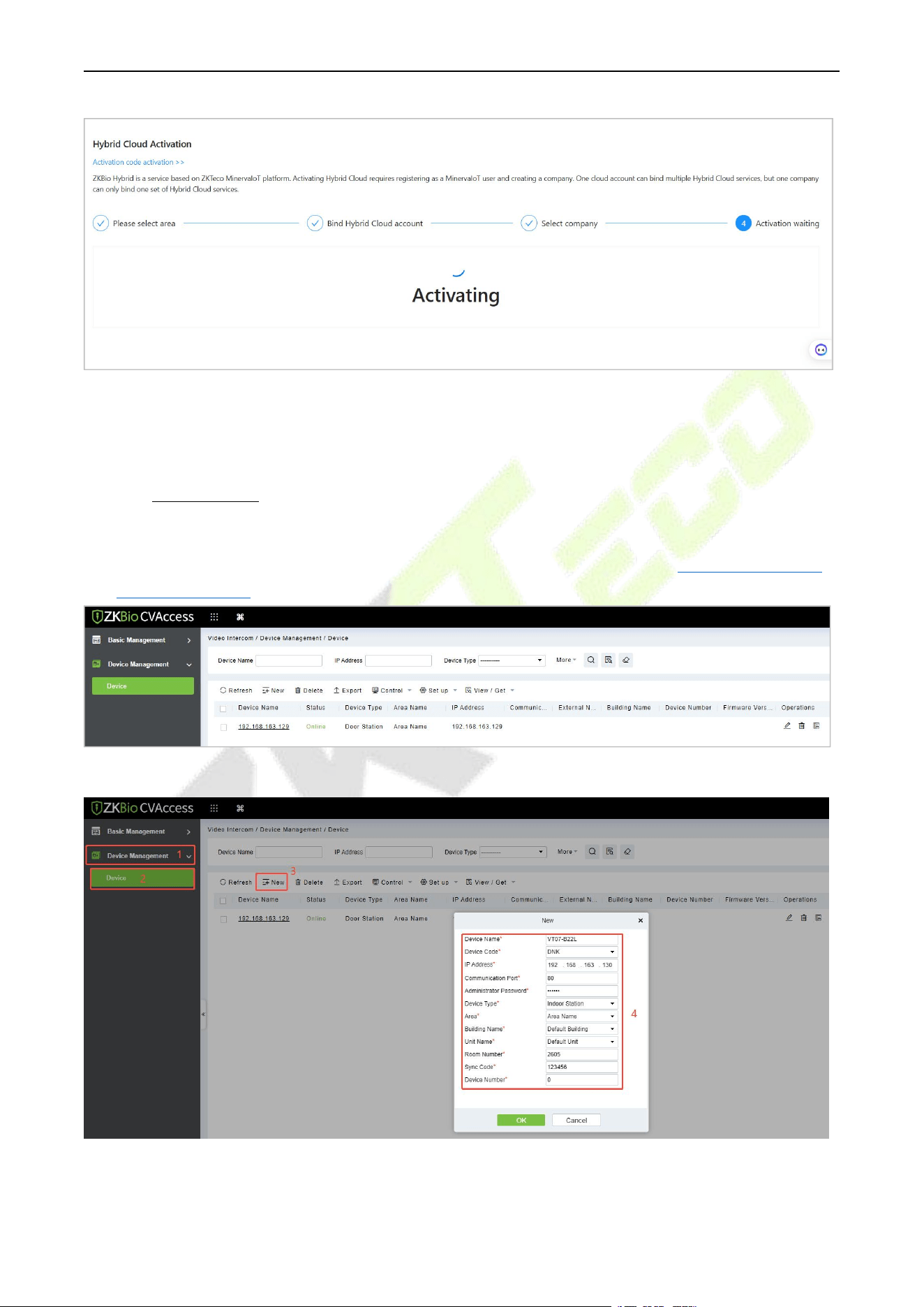
F34 User Manual
P a g e | 151 Copyright © 2026 ZKTECO CO., LTD. All rights reserved.
The specific installation and activation steps of the ZKBio CVConnect client can refer to ZKBio Zexus Mobile App
User Manual.
26.2.2 Add Device
1. Add the device to the Access Module of the software. Then the device will be automatically
synchronized to the Video Intercom module. (The adding method can refer to 22 Connect to ZKBio
CVAccess Software)
2. Click Video Intercom > Device Management > Device > New to add the indoor monitor.
Device Name: Enter the name of the indoor monitor.
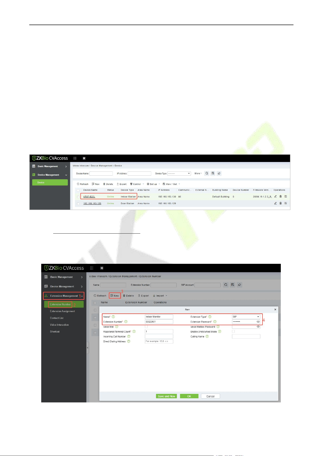
F34 User Manual
P a g e | 152 Copyright © 2026 ZKTECO CO., LTD. All rights reserved.
Device Code: Set as DNK.
IP Address: Enter the IP address of the indoor monitor.
Communication Port: 80 by default.
Administrator Password: 123456 by default.
Device Type: Set as Indoor Station.
Area/ Building Name/Unit Name: Select from the drop-down list.
Room Number: Customize the number of the indoor monitor.
Sync Code: Can be customized by the user. (It is used when a resident has multiple indoor monitors.
The indoor monitors which have the same Sync Code will be called at the same time.)
Device Number: The setting range is 0-9. For example, if there is only one indoor monitor in the room,
the device number will be 0. If there are two units, one will be 0 and the other will be 1, and so on.
After the addition is successful, the indoor monitor will be displayed in the device list.
26.2.3 Create Extension Numbers
Click Video Intercom > Extension Management > Extension Number > New to create extension
numbers.
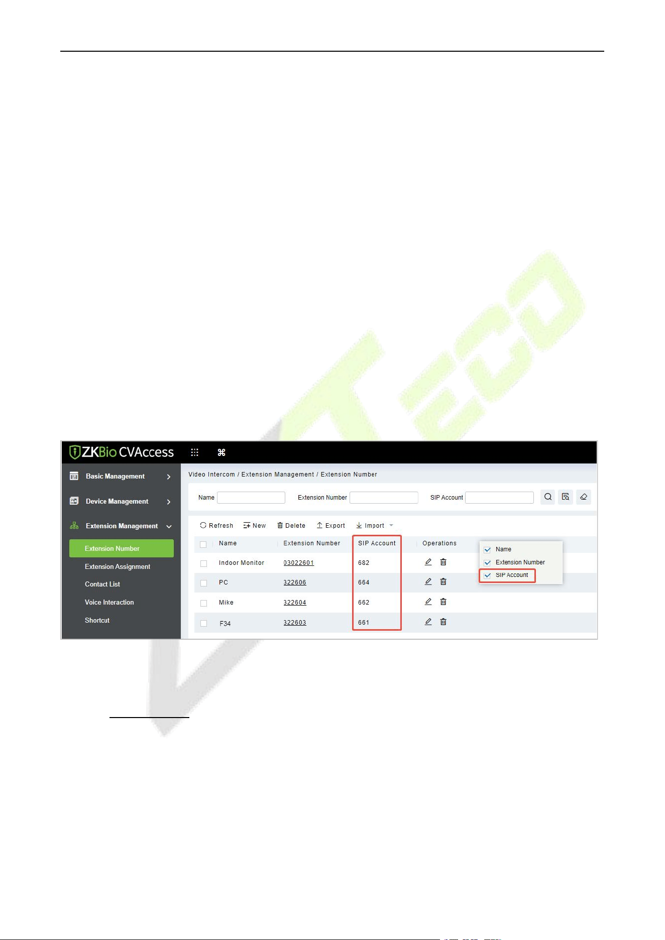
F34 User Manual
P a g e | 153 Copyright © 2026 ZKTECO CO., LTD. All rights reserved.
Name: Customize the extension name. If it is a residential scene, the name can be set to the room
number; if it is an office scene, the name can be set to the work number and name information.
Extension Type: SIP by default.
Extension number: Customize the extension number, it can be up to 8-digit; for example, the
number of Room 401, Unit 2, Building 1 can be defined as 01020401 for quick internal identification.
Extension Password: User's SIP account password, which can be used to request account registration
from the SIP service.
Registered Terminal Count: The maximum number of terminals that a user can register to the same
number. When the number of concurrent registrations is 1, it means that new registrations are
allowed to preempt the registration address. When the number of concurrent registrations is 2 or
more, new registrations will be automatically blocked once the number of registrations reaches the
limit.
After the user creates the extension number, the system will automatically generate a SIP account. For
example, assuming the user has created the extension number 322603, the system automatically
generates the SIP account as 661, so the SIP User Name used on the terminal is 661.
Note:
1) The SIP Account column is hidden by default. You can right-click the row which Operations is in and
check the SIP Account to display it.
2) If you use a PBX, the extension number will be directly used, and the SIP account list will be empty.
26.2.4 Contact List
If you need to enable different devices or personnel to view a limited number of contacts, you can
configure the contact list.
1. Click Extension Management > Contact List > New to create a contact list.
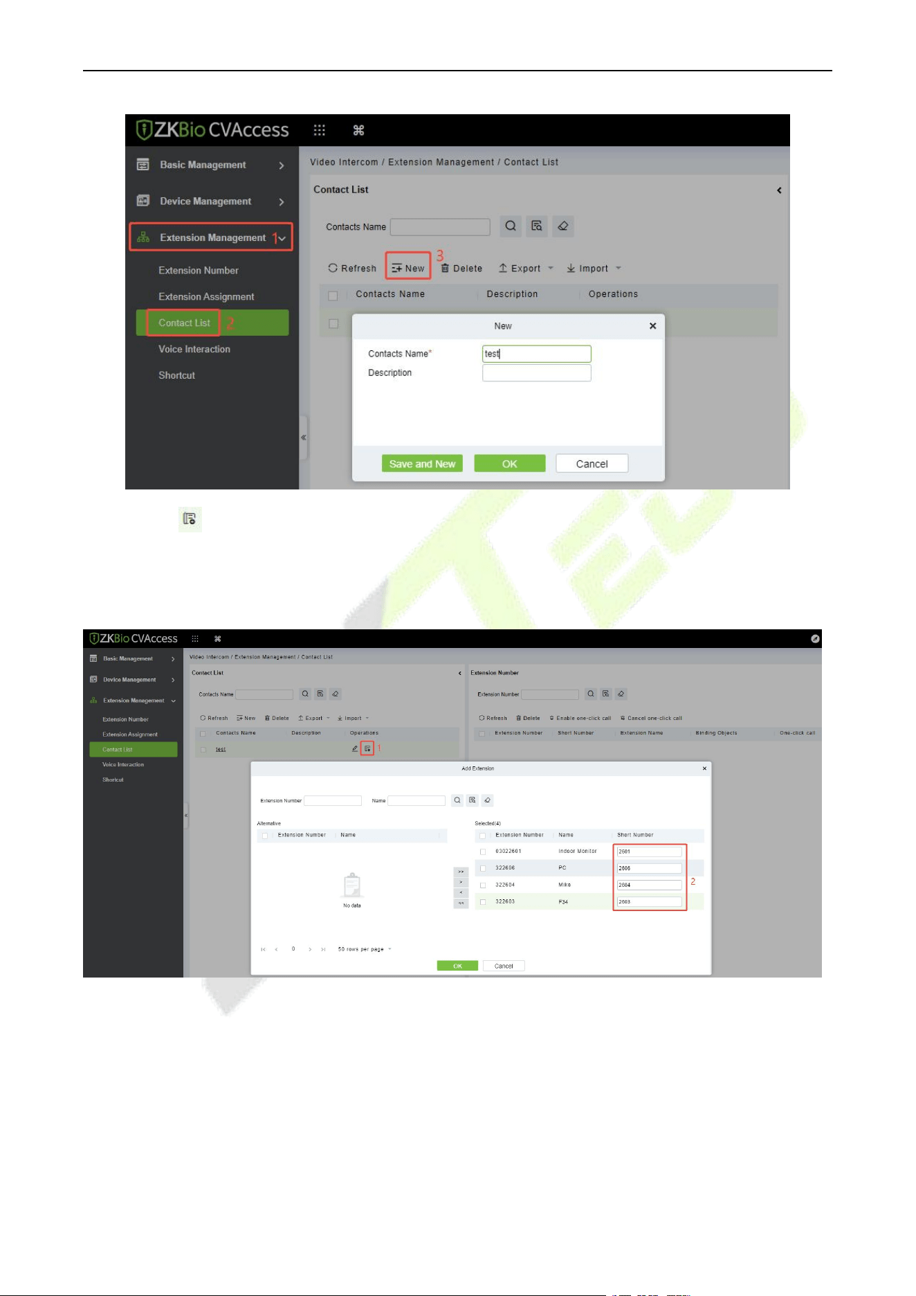
F34 User Manual
P a g e | 154 Copyright © 2026 ZKTECO CO., LTD. All rights reserved.
2. Click the icon to add extension numbers to the contact list. During the process of adding
extension numbers, you can define a short number for the extension on the right, for example, if the
number for Room 1101 is defined as 101. After defining and synchronizing the short number to the
device, the device can then dial the short number 101 to call that room.
Note:
1) If you add an extension number to the contact list without editing the short number, and you wish to
edit it later, you will need to delete the extension number from that contacts and then edit it when re-
adding, or delete it and use the import function afterward.
2) If the device is set to be a fence terminal, please do not define the short number of the indoor
monitors. You just need to input the block, unit and room number to call the indoor monitor.
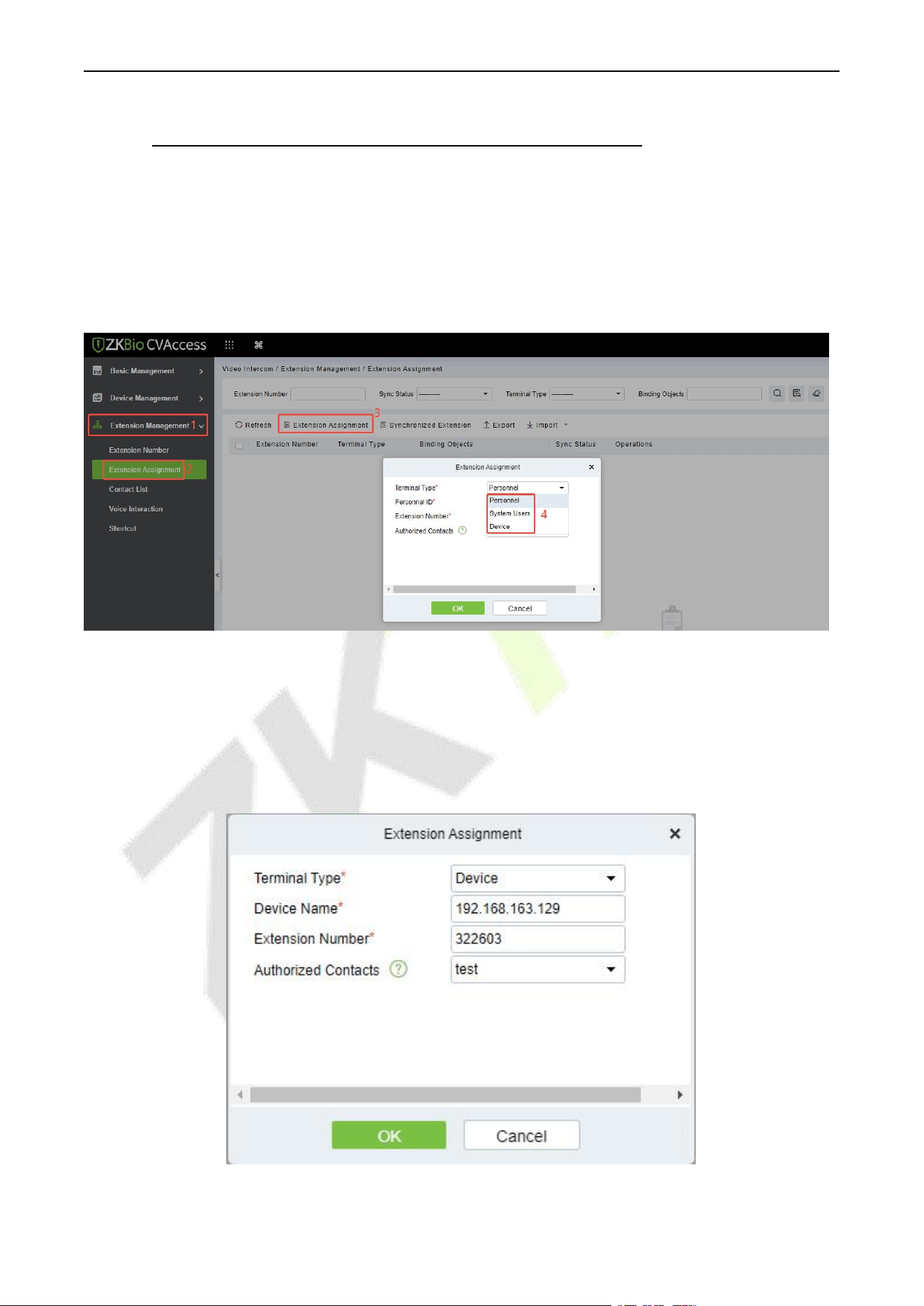
F34 User Manual
P a g e | 155 Copyright © 2026 ZKTECO CO., LTD. All rights reserved.
26.2.5 Assignment of Extension Numbers and SIP Accounts
The extension number or SIP account can be assigned to personnel, devices or system users. After
allocation, personnel and users' APP will be able to directly use video intercom for communication. The
device can also be used directly without manual additional configuration.
Click Extension Management > Extension Assignment > Extension Assignment, select the Terminal
Type.
Device Account Assignment
1. Select the Terminal Type as Device.
2. Select the device need to be bound (device or indoor monitor) and the extension number. The
account information will be automatically synchronized to the device. Select the Authorized Contacts
to assign the contact list to the device; only after the assignment can the device call room
numbers/short numbers or make calls through the contact list search.
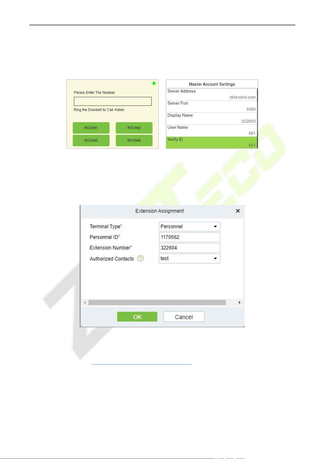
F34 User Manual
P a g e | 156 Copyright © 2026 ZKTECO CO., LTD. All rights reserved.
3. After successful assignment, a green dot will appear in the upper right corner of the call page,
indicates that the device is connected to the server. You can also enter [Intercom] > [SIP Settings] >
[Local Settings] > [Primary Account Settings] to see that SIP server and account information have
been automatically written, as shown in the following figure.
Personnel Account Assignment (ZKBio Zexus App)
1. Select the Terminal Type as Personnel.
2. Select the person to be assigned an account and the extension number. Select the Authorized
Contacts to assign the contact list to the individual, and after the assignment, the individual can view
the contacts in the contact list upon logging into the ZKBio Zexus App.
Note:
1) Before assign account to the personnel, you need first add personnel in ZKBio CVAccess. The adding
method can refer to 20 Connect to ZKBio CVAccess Software.
2) The personnel need to enable APP Login. (Click Personnel > Personnel > Person > More > Enable
APP Login.) Once a person has enabled APP login, they can directly access the Video Intercom feature
upon logging into the App.
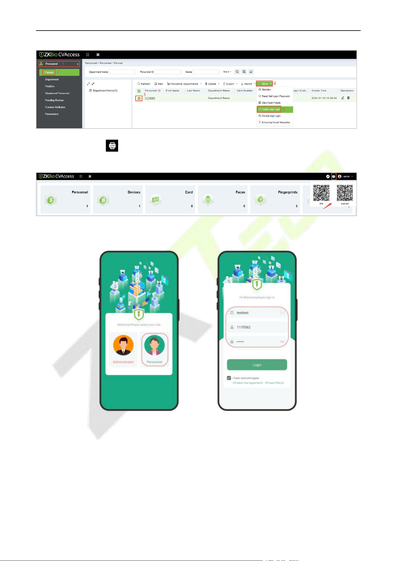
F34 User Manual
P a g e | 157 Copyright © 2026 ZKTECO CO., LTD. All rights reserved.
3) You can click the icon at the right top corner of the ZKBio CVAccess interface to scan the QR
code to install the ZKBio Zexus App.
3. After successful assignment, the personnel can login to the App. Select the role-Personnel , enter the
account information, and click Login.
Organization Name: Scan the organization code you get before. (Go to ZKBio CVAccess web, enter
System > System Management >Cloud Setting >APP enterprise QR Code, or go to ZKBio
CVConnect client, scan the ZKBio CVConnect Client Information QR Code.)
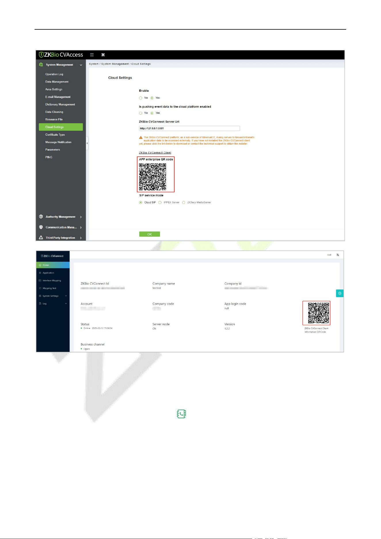
F34 User Manual
P a g e | 158 Copyright © 2026 ZKTECO CO., LTD. All rights reserved.
Account & Password: The personnel ID & password (default: 123456).
4. Click Application Center > Video Call to enter the video call application, and the status will be displayed as
Connected. If the person has not assigned an extension number, entering the application will prompt "you
have not assigned anextension number, please contact the administrator". Then you can directly enter the
extension number of the device or click the icon to search for the device and call it.
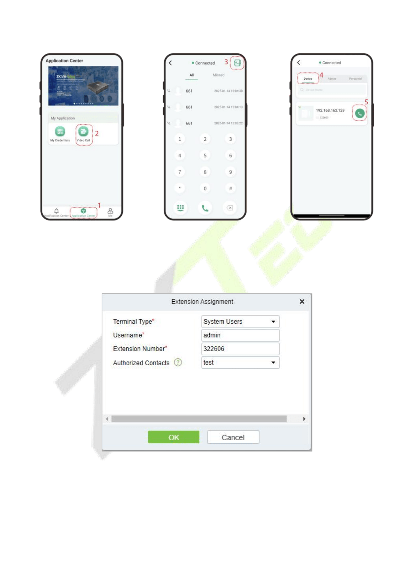
F34 User Manual
P a g e | 159 Copyright © 2026 ZKTECO CO., LTD. All rights reserved.
System User Account Assignment (ZKBio Zexus App)
1. Select the Terminal Type as System Users.
2. Select the system user to be assigned an account and the extension number. Select the Authorized
Contacts to assign the contact list to the admin, and after the assignment, the admin can view the
contacts in the contact list upon logging into the ZKBio Zexus App.
3. After successful assignment, the admin can login to the App. Select the role-Administrator, enter the
account information, and click Login.
Organization Name: Scan the organization code you get before.
Account & Password: The administrator account; Same account & password as ZKBio CVAccess.
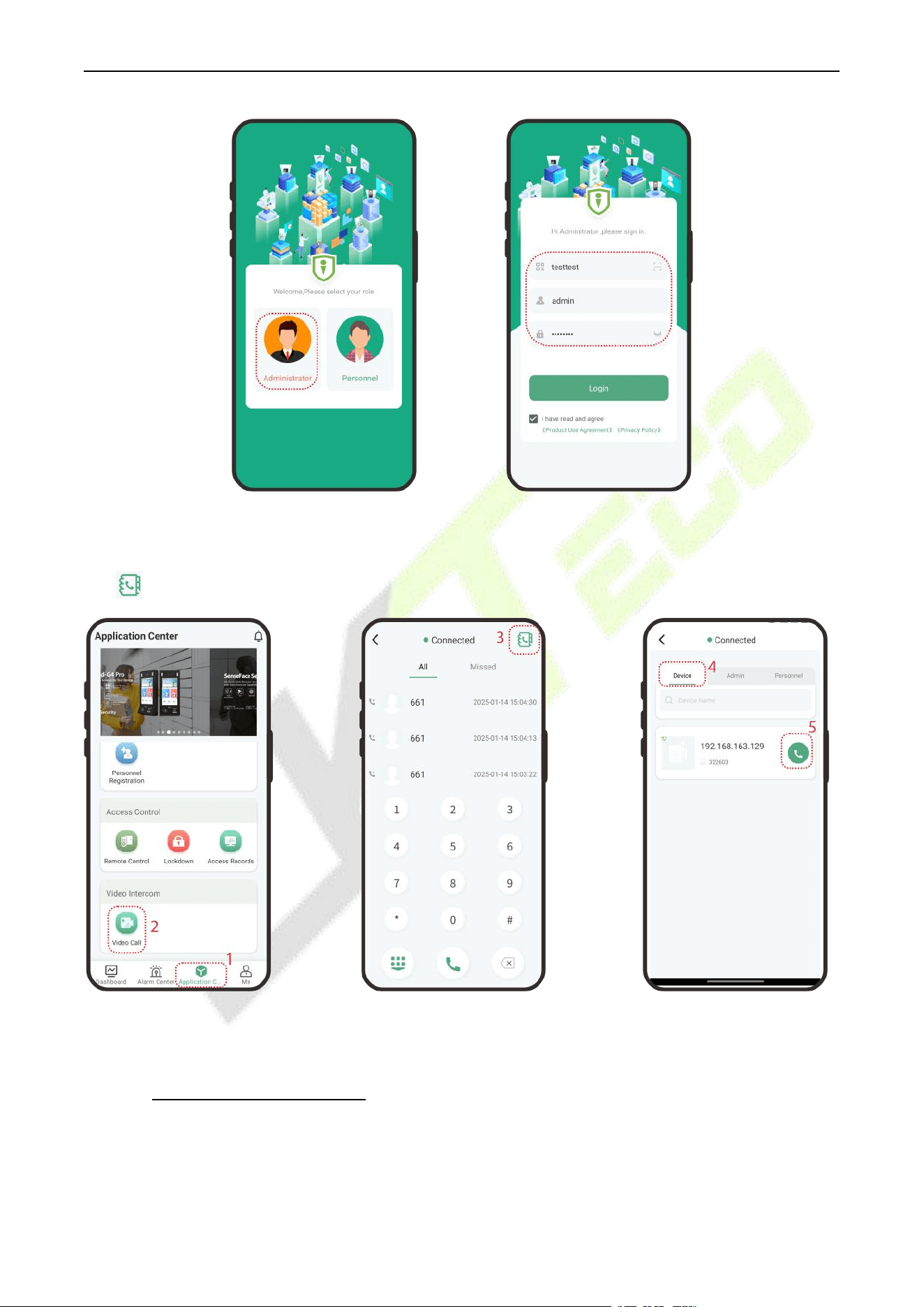
F34 User Manual
P a g e | 160 Copyright © 2026 ZKTECO CO., LTD. All rights reserved.
4. Click Application Center > Video Call to enter the video call application, and the status will be
displayed as Connected. Then you can directly enter the extension number of the device or click the
icon to search for the device and call it.
The App complete operation steps please refer to the ZKBio Zexus Mobile App User Manual.
26.2.6 PC Client Functionality
To use the BioTalk Pro PC client, please contact the appropriate person for an installation package.
Operation Guide
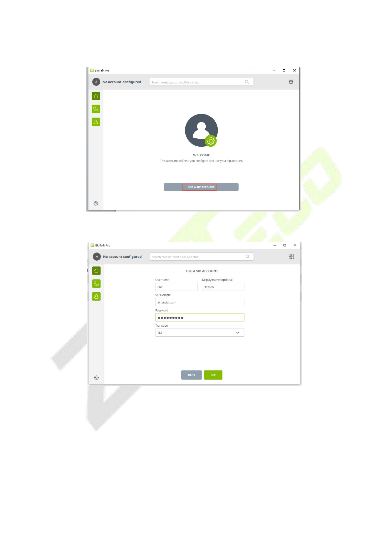
F34 User Manual
P a g e | 161 Copyright © 2026 ZKTECO CO., LTD. All rights reserved.
Step 1: Configure the SIP account: Click USE A SIP ACCOUNT button.
Step 2: Fill in the SIP account information in order and click USE.
Username: Enter the SIP account. (Note: You need to create a new SIP account for the PC client in
ZKBio CVAccess, then you can use the account to login to the PC client.)
Display Name: It is the extension number.
SIP Domain: The SIP Server Domain. (Go to ZKBio CVConnect client, click Application > Innosip >
Enter, the EndPoint address is “https://innosip.zktecoiot.com”. Then 'zktecoiot.com' is the actual SIP
server domian you need to enter on the PC Client.)
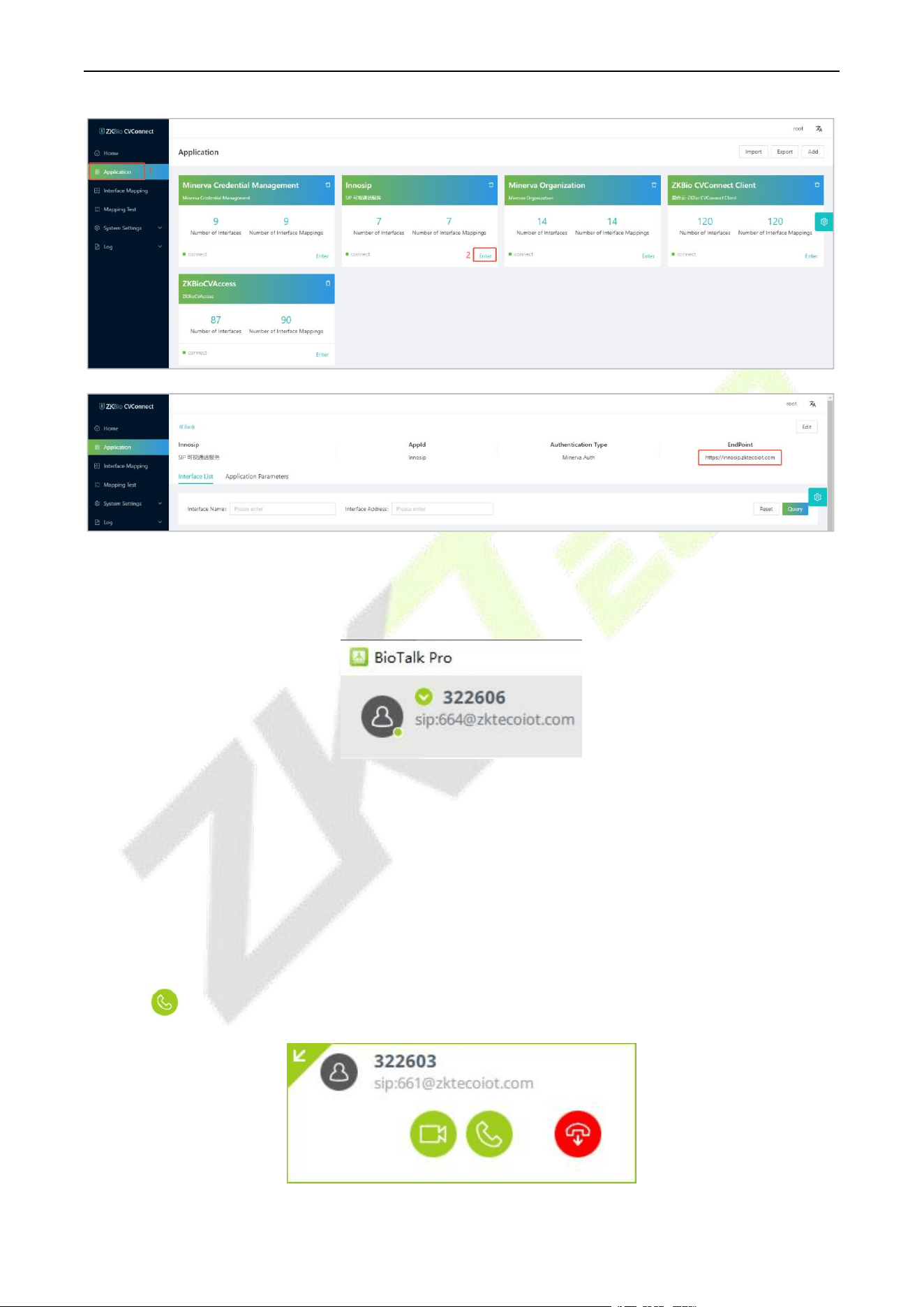
F34 User Manual
P a g e | 162 Copyright © 2026 ZKTECO CO., LTD. All rights reserved.
Password: The extension password of the SIP account for PC client.
Transport: Transportation Protocol, TLS by default.
Wait 1 minute until the status shows Connected, as shown below:
Note: In the Cloud SIP mode, if dialing is required, the PC Client should dial directly to the target SIP
account. For example, if the extension number created on ZKBio CVAccess is 322603, the corresponding
generated SIP account is 661, then the PC Client should dial 661 when making a call. Therefore, it is
recommended to directly create a contact in the address book with the number 661.
At this point you can start to use it normally, the PC client, the device and the App can call and answer
each other.
When the PC Client receives a call, a window alert will pop up in the lower right corner of the desktop.
Click the icon to accept it.
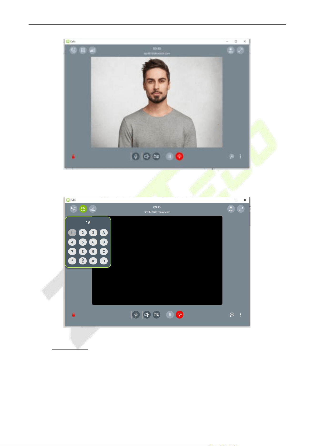
F34 User Manual
P a g e | 163 Copyright © 2026 ZKTECO CO., LTD. All rights reserved.
You can open the door by clicking on the keypad and entering the DTMF value of the device, e.g. the
default value of ZKTeco device is 1, so you can click on 1 at the keypad.
26.2.7 Make a Call
Two-way calls can be made between the device, indoor monitor, ZKBio Zexus App, and PC client (BioTalk
Pro).
Device Call the Indoor Monitor (VT07-B26L-W / VT07-B22L)
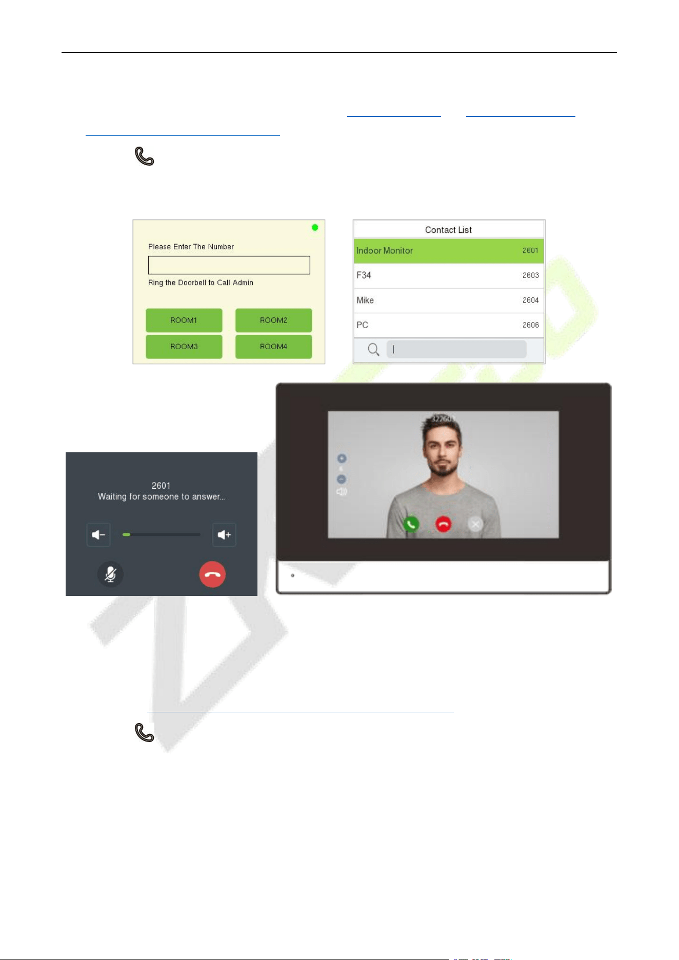
F34 User Manual
P a g e | 164 Copyright © 2026 ZKTECO CO., LTD. All rights reserved.
1. Add the indoor monitor on the ZKBio CVAccess software, then assign an extension number to the
indoor monitor. (The operations steps can refer to 26.2.2 Add Device and 26.2.5 Assignment of
Extension Numbers and SIP Accounts)
2. Press the key on the device and enter the Short Number of the indoor monitor in the pop-up
interface of the device. Or press the Up key on the call page to open the contact list and search for the
indoor monitor to call it.
or
Device Call the Phone (ZKBio Zexus App)
1. On the ZKBio CVAccess software, assign an extension number to the personnel. (The operations steps
can refer to 23.2.5 Assignment of Extension Numbers and SIP Accounts)
2. Press the key on the device and enter the Short Number of the personnel in the pop-up interface
of the device. Or press the Up key on the call page to open the contact list and search for the
personnel to call him/her.
2601
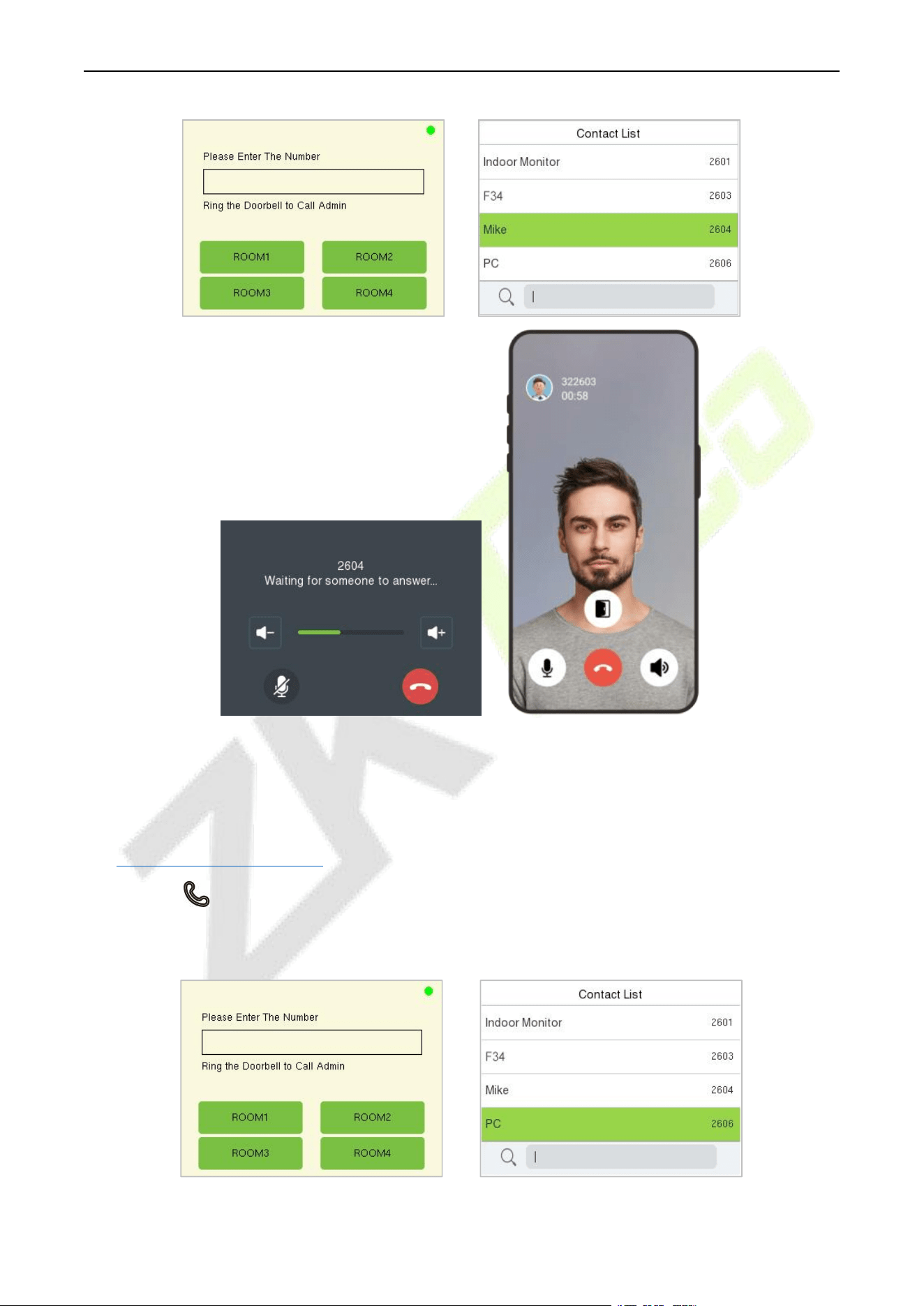
F34 User Manual
P a g e | 165 Copyright © 2026 ZKTECO CO., LTD. All rights reserved.
or
Device Call the PC Client (BioTalk Pro)
1. Install the BioTalk Pro software and configure the SIP account. (The operations steps can refer to
26.2.6 PC Client Functionality)
2. Press the key on the device and enter the Short Number of the PC client in the pop-up interface of
the device. Or press the Up key on the call page to open the contact list and search for the PC client to
call it.
or
2604
2606
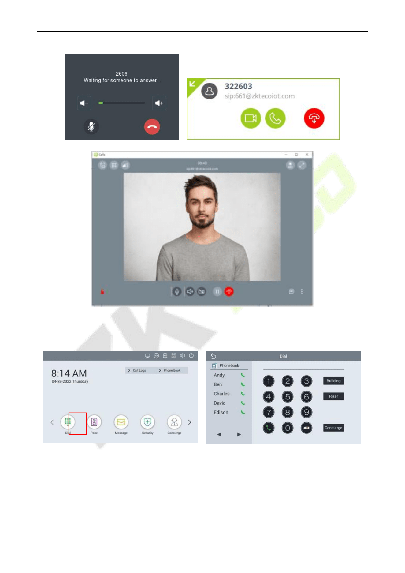
F34 User Manual
P a g e | 166 Copyright © 2026 ZKTECO CO., LTD. All rights reserved.
Indoor Monitor Call
Click the Dial icon, then enter the SIP Account to make a call.
Note: The indoor monitor is not supported the assignment of the contact list in ZKBio CVAccess.
Phone Call
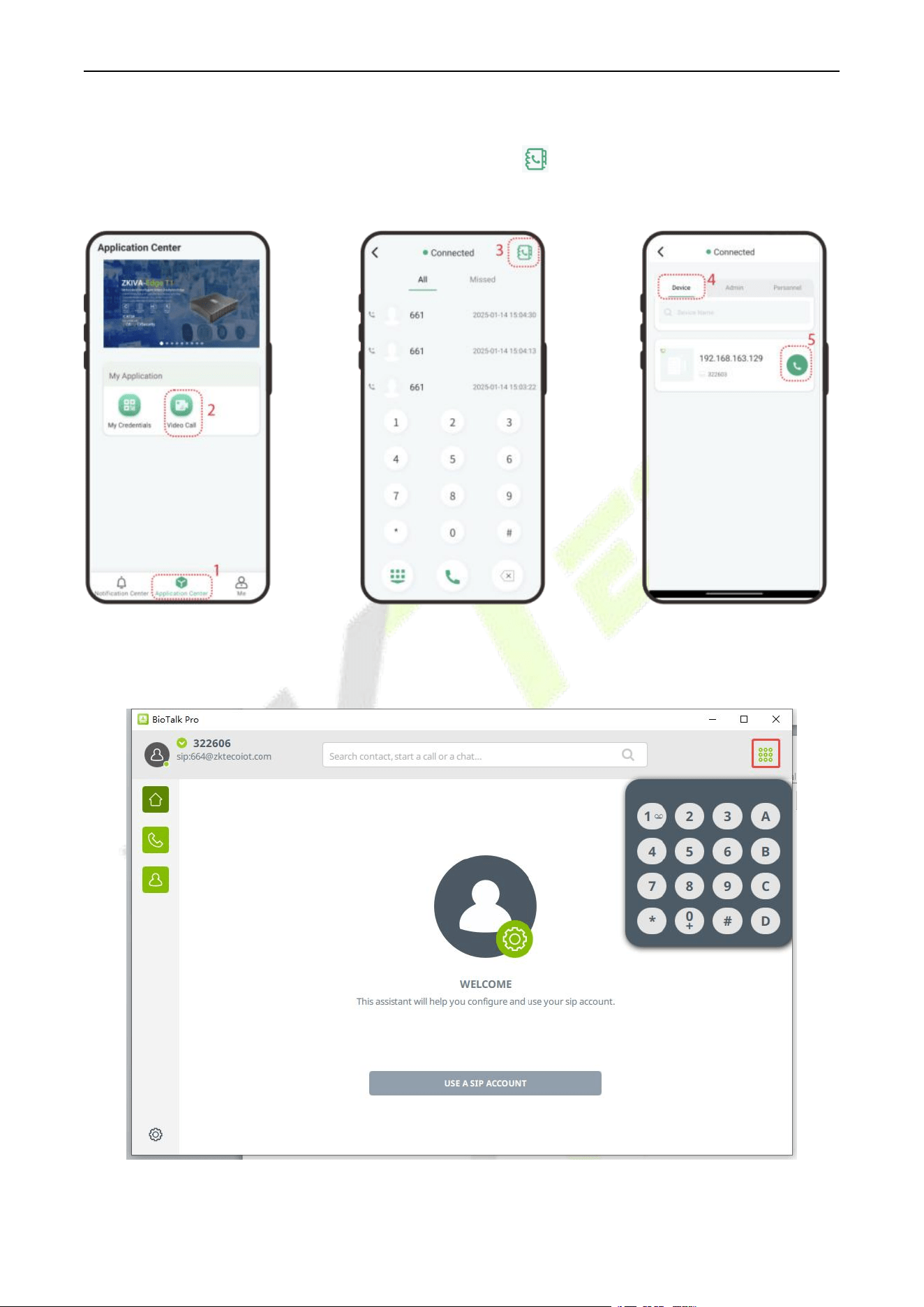
F34 User Manual
P a g e | 167 Copyright © 2026 ZKTECO CO., LTD. All rights reserved.
Login to the ZKBio Zexus App, click Application Center > Video Call to enter the video call application,
Then you can directly enter the extension number or click the icon to search for the one you want to
call.
PC Client (BioTalk Pro) Call
Open the BioTalk Pro client, click the keypad and enter the the SIP Account to make a call.
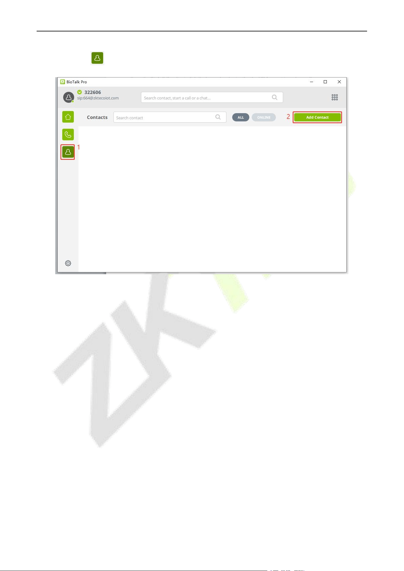
F34 User Manual
P a g e | 168 Copyright © 2026 ZKTECO CO., LTD. All rights reserved.
You can click the icon > Add Contact to add the contact list manually.

F34 User Manual
P a g e | 169 Copyright © 2026 ZKTECO CO., LTD. All rights reserved.
Appendix 1
Privacy Policy
Notice:
To help you better use the products and services of ZKTeco and its affiliates, hereinafter referred as "we",
"our", or "us", the smart service provider, we consistently collect your personal information. Since we
understand the importance of your personal information, we took your privacy sincerely and we have
formulated this privacy policy to protect your personal information. We have listed the privacy policies
below to precisely understand the data and privacy protection measures related to our smart products
and services.
Before using our products and services, please read carefully and understand all the rules and
provisions of this Privacy Policy. If you do not agree to the relevant agreement or any of its terms,
you must stop using our products and services.
I. Collected Information
To ensure the normal product operation and help the service improvement, we will collect the
information voluntarily provided by you or provided as authorized by you during registration and use
or generated as a result of your use of services.
1. User Registration Information: At your first registration, the feature template (Fingerprint
template/Face template/Palm template) will be saved on the device according to the device
type you have selected to verify the unique similarity between you and the User ID you have
registered. You can optionally enter your Name and Code. The above information is necessary for
you to use our products. If you do not provide such information, you cannot use some features of
the product regularly.
2. Product information: According to the product model and your granted permission when you
install and use our services, the related information of the product on which our services are used
will be collected when the product is connected to the software, including the Product Model,
Firmware Version Number, Product Serial Number, and Product Capacity Information. When you
connect your product to the software, please carefully read the privacy policy for the
specific software.
II. Product Security and Management
1. When you use our products for the first time, you shall set the Administrator privilege before
performing specific operations. Otherwise, you will be frequently reminded to set the

F34 User Manual
P a g e | 170 Copyright © 2026 ZKTECO CO., LTD. All rights reserved.
Administrator privilege when you enter the main menu interface. If you still do not set the
Administrator privilege after receiving the system prompt, you should be aware of the
possible security risk (for example, the data may be manually modified).
2. All the functions of displaying the biometric information are disabled in our products by default.
You can choose Menu > System Settings to set whether to display the biometric information. If
you enable these functions, we assume that you are aware of the personal privacy security risks
specified in the privacy policy.
3. Only your user ID is displayed by default. You can set whether to display other user verification
information (such as Name, Department, Photo, etc.) under the Administrator privilege. If you
choose to display such information, we assume that you are aware of the potential security
risks (for example, your photo will be displayed on the device interface).
4. The camera function is disabled in our products by default. If you want to enable this function to
take pictures of yourself for attendance recording or take pictures of strangers for access control,
the product will enable the prompt tone of the camera. Once you enable this function, we
assume that you are aware of the potential security risks.
5. All the data collected by our products is encrypted using the AES 256 algorithm. All the data
uploaded by the Administrator to our products are automatically encrypted using the AES 256
algorithm and stored securely. If the Administrator downloads data from our products, we
assume that you need to process the data and you have known the potential security risk. In such
a case, you shall take the responsibility for storing the data. You shall know that some data
cannot be downloaded for sake of data security.
6. All the personal information in our products can be queried, modified, or deleted. If you no
longer use our products, please clear your personal data.
III. How we handle personal information of minors
Our products, website and services are mainly designed for adults. Without consent of parents or
guardians, minors shall not create their own account. If you are a minor, it is recommended that you
ask your parents or guardian to read this Policy carefully, and only use our services or information
provided by us with consent of your parents or guardian.
We will only use or disclose personal information of minors collected with their parents' or guardians'
consent if and to the extent that such use or disclosure is permitted by law or we have obtained their
parents' or guardians' explicit consent, and such use or disclosure is for the purpose of protecting
minors.
Upon noticing that we have collected personal information of minors without the prior consent from
verifiable parents, we will delete such information as soon as possible.

F34 User Manual
P a g e | 171 Copyright © 2026 ZKTECO CO., LTD. All rights reserved.
IV. Others
You can visit https://www.zkteco.com/cn/index/Index/privacy_protection.html to learn more about
how we collect, use, and securely store your personal information. To keep pace with the rapid
development of technology, adjustment of business operations, and to cope with customer needs, we
will constantly deliberate and optimize our privacy protection measures and policies. Welcome to visit
our official website at any time to learn our latest privacy policy.

F34 User Manual
P a g e | 172 Copyright © 2026 ZKTECO CO., LTD. All rights reserved.
Eco-friendly Operation
The product's "eco-friendly operational period" refers to the time during which this
product will not discharge any toxic or hazardous substances when used in accordance
with the prerequisites in this manual.
The eco-friendly operational period specified for this product does not include batteries
or other components that are easily worn down and must be periodically replaced. The
battery's eco-friendly operational period is 5 years.
Hazardous or Toxic substances and their quantities
Component
Name
Hazardous/Toxic Substance/Element
Lead
(Pb)
Mercury
(Hg)
Cadmium
(Cd)
Hexavalent
Chromium
(Cr6+)
Polybrominated
Biphenyls
(PBB)
Polybrominated
Diphenyl Ethers
(PBDE)
Chip
Resistor
×
○
○
○
○
○
Chip
Capacitor
×
○
○
○
○
○
Chip
Inductor
×
○
○
○
○
○
Diode
×
○
○
○
○
○
ESD
component
×
○
○
○
○
○
Buzzer
×
○
○
○
○
○
Adapter
×
○
○
○
○
○
Screws
○
○
○
×
○
○
This table is prepared in accordance with the provisions of SJ/T 11364.
○ indicates that the total amount of toxic content in all the homogeneous materials is below the limit as
specified in GB/T 26572.
× indicates that the total amount of toxic content in all the homogeneous materials exceeds the limit as
specified in GB/T 26572.
Note: 80% of this product’s components are manufactured using non-toxic and eco-friendly materials.
The components which contain toxins or harmful elements are included due to the current economic or
technical limitations which prevent their replacement with non-toxic materials or elements.

ZKTeco Industrial Park, No. 32, Industrial Road,
Tangxia Town, Dongguan, China.
Phone : +86 769 - 82109991
Fax : +86 755 - 89602394
www.zkteco.com
Copyright © 2026 ZKTECO CO., LTD. All Rights Reserved.