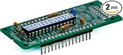

Serial Wombat 18AB Chip User Guide
Version 2.1.0_A (Corresponds to Serial Wombat 18AB firmware version 2.1.0)
An Open Source Project
Created by
Broadwell Consulting Inc.

Table of contents:
Table of contents: ........................................................................................................................ 2
Overview ....................................................................................................................................... 5
Serial Wombat Trademark ........................................................................................................... 9
Arduino Library .......................................................................................................................... 10
Python / MicroPython Library ................................................................................................... 12
C# library .................................................................................................................................... 13
Circuit Construction .................................................................................................................. 14
Serial Wombat 18AB PCB Board .............................................................................................. 16
Basic Assembly ..................................................................................................................... 16
Address Resistor (optional) ................................................................................................... 17
UART Mode (optional) ........................................................................................................... 18
I2C Pull up resistors
(optional) ............................................................................................... 18
5V pins and traces ................................................................................................................. 18
5V to 3.3V LDO Regulator circuit (optional) ........................................................................... 19
FTDI cable connector ............................................................................................................ 19
ESP-01 Module connector ..................................................................................................... 20
Qwiic/Stemma Connector Pads ............................................................................................. 21
OLED / I2C port ..................................................................................................................... 21
Surface mount Resistor / Capacitor alternate pads ............................................................... 21
Header Pin Connectors ......................................................................................................... 22
RST Pin ................................................................................................................................. 22
Pin
Modes ................................................................................................................................... 22
Digital GPIO Input Pin Mode (0) .......................................................................................... 24
Digital Output Pin Mode ...................................................................................................... 24
Analog Input Pin Mode ........................................................................................................ 26
Servo Output Pin Mode ....................................................................................................... 29
Throughput Consumer Pin Mode ....................................................................................... 32
Quadrature Encoder Input Pin Mode ..................................................................................... 33
Watchdog Pin Mode ............................................................................................................... 35
Protected Output Pin Mode ................................................................................................... 37
Debounced Input Pin Mode
................................................................................................... 41
TM1637 Seven Segment Display Pin Mode .......................................................................... 44
WS2812 RGB LED Pin Mode ................................................................................................ 45
Hardware UART Receive and Transmit Pin Mode ............................................................ 50
Software UART Receive and Transmit Mode ........................................................................ 52
Processed Input Testing Pin Mode ........................................................................................ 54
Matrix Keypad Pin mode ........................................................................................................ 55
PWM Pin Mode ...................................................................................................................... 59
Serial Wombat 18AB Chip User Guide Page 2 of 119
V2.1.0_A

Pulse Timer Pin Mode ......................................................................................................... 60
Frame Timer Pin Mode .......................................................................................................... 63
Capacitive Touch (CapTouch) Pin Mode ................................................................................ 64
Resistance Input Pin Mode .................................................................................................... 68
Pulse on Change Pin Mode ................................................................................................... 70
High Frequency Servo ........................................................................................................... 72
Ultrasonic Distance Sensor Driver ......................................................................................... 74
Liquid Crystal Character LCD Display Driver ......................................................................... 75
High Speed Clock .................................................................................................................. 77
High
Speed Counter .............................................................................................................. 78
VGA Output Pin Mode ........................................................................................................... 80
PS2 Keyboard Input Mode ..................................................................................................... 82
Serial Wombat 18AB Pin to Pin interactions ........................................................................... 84
Serial Wombat 18AB Public Data Sources .............................................................................. 84
Public Data Sources: ............................................................................................................. 86
SW_DATA_SOURCE_INCREMENTING_NUMBER(65) ................................................. 86
SW_DATA_SOURCE_1024mvCounts(66) ...................................................................... 86
SW_DATA_SOURCE_FRAMES_RUN_LSW(67) ............................................................ 86
SW_DATA_SOURCE_FRAMES_RUN_MSW(68) ........................................................... 86
SW_DATA_SOURCE_OVERRUN_FRAMES(69) ........................................................... 86
SW_DATA_SOURCE_TEMPERATURE(70) ................................................................... 86
SW_DATA_SOURCE_PACKETS_RECEIVED(71) .........................................................
86
SW_DATA_SOURCE_ERRORS(72) ............................................................................... 87
SW_DATA_SOURCE_FRAMES_DROPPED(73) ........................................................... 87
SW_DATA_SOURCE_SYSTEM_UTILIZATION(74) ........................................................ 87
SW_DATA_SOURCE_VCC_mVOLTS(75) ...................................................................... 87
SW_DATA_SOURCE_VBG_COUNTS_VS_VREF(76) ................................................... 87
SW_DATA_SOURCE_RESET_REGISTER(77) .............................................................. 87
SW_DATA_SOURCE_LFSR(78) ..................................................................................... 87
SW_DATA_SOURCE_PIN_0_MV(100) ........................................................................... 87
SW_DATA_SOURCE_2HZ_SQUARE(164) .................................................................... 87
SW_DATA_SOURCE_2HZ_SAW(165) ........................................................................... 87
SW_DATA_SOURCE_1HZ_SQUARE(167) .................................................................... 88
SW_DATA_SOURCE_1HZ_SAW(168) ........................................................................... 88
SW_DATA_SOURCE_2SEC_SQUARE(170) .................................................................. 88
SW_DATA_SOURCE_2SEC_SAW(171) ......................................................................... 88
SW_DATA_SOURCE_8SEC_SQUARE(173) .................................................................. 88
SW_DATA_SOURCE_8SEC_SAW(174) ......................................................................... 88
SW_DATA_SOURCE_65SEC_SQUARE(176) ................................................................ 88
SW_DATA_SOURCE_65SEC_SAW(177) ....................................................................... 88
Processed Input
Pin Modes ...................................................................................................... 89
Serial Wombat 18AB Chip User Guide Page 3 of 119
V2.1.0_A

Scaled Output Pin Modes ......................................................................................................... 91
Timing Resource Manager ........................................................................................................ 93
Error Handling ............................................................................................................................ 94
Serial Wombat Error Codes ................................................................................................... 94
Powerup Self-Configuration ..................................................................................................... 98
Simultaneous UART and I2C interfacing from 2 Hosts .......................................................... 99
Sleep Mode ............................................................................................................................... 100
Unique Identifier ...................................................................................................................... 101
Serial Wombat 18AB Temperature Sensor ............................................................................ 102
Serial Wombat 18AB User RAM Buffer ..................................................................................
103
Serial Wombat 18AB User RAM Buffer Queues .................................................................... 103
Serial Wombat 18AB Firmware Structure .............................................................................. 104
Executive Structure .............................................................................................................. 105
Pin State Machines .............................................................................................................. 105
Serial Wombat 18AB Throughput Management ................................................................... 107
Firmware Updates (Bootloader) ............................................................................................. 109
Serial Wombat Panel Application ........................................................................................... 110
Protocol Analyzer .................................................................................................................... 114
Troubleshooting ....................................................................................................................... 115
Step 1: Check the basics .................................................................................................... 115
Step 2: Check the YouTube video and comments .............................................................. 117
Additional Resources: ............................................................................................................. 118
YouTube ............................................................................................................................... 118
Arduino Library ..................................................................................................................... 118
Serial Wombat 18AB firmware ............................................................................................. 118
Support and Technical Assistance ........................................................................................ 118
Revision History ...................................................................................................................... 119
Serial Wombat 18AB Chip User Guide Page 4 of 119
V2.1.0_A

Overview
The Serial Wombat 18 chip family is designed to add smart I/O capability to Arduino, Raspberry
Pi, PCs, MicroPython boards or other systems capable of communicating over I2C or UART.
Each Serial Wombat 18AB chip adds up to 18 I/O pins. Each pin runs its own state machine
1000 times per second, allowing the chip to offload many common hardware interfacing tasks
from the host.
The Serial Wombat 18AB firmware is open source under MIT license available here:
https://github.com/BroadwellConsultingInc/SerialWombat
The Serial Wombat 18AB chip is a peripheral chip that is commanded by a host device. It is not
a device that runs downloaded user code directly. An Arduino C++ library is available to control
the Serial Wombat 18AB chip from an Arduino host over I2C or UART through the Arduino
Library Manager. Libraries are also available for C# and MicroPython which abstract the
functionality of the Serial Wombat 18AB chip into easy to use interfaces. As much as
technically possible, the Arduino, MicroPython and C# libraries implement the same interfaces,
so example code and videos are typically applicable to all platforms.
The Serial Wombat communication protocol is available for users that wish to interface to the
Serial Wombat 4B chip from other platforms.
The Serial Wombat 18AB firmware is heavily commented using Doxygen compatible
commenting. The compiled Doxygen documentation is available here:
https://broadwellconsultinginc.github.io/SerialWombat/sw18AB/index.html
The documentation embedded in the firmware exposes the internal workings of the Serial
Wombat chip and its protocol. This documentation is typically not needed in order to use the
Serial Wombat 18AB chip from Arduino, C# or MicroPython due to the availability of a wrapper
library.
Each Serial Wombat pin runs an individual state machine every 1mS allowing that pin to solve
common embedded systems problems. Pin modes can be mixed and matched (for example,
two debounced inputs, an analog input, and a servo output).
The Serial Wombat 18AB chip supports the following pin modes:
SW18AB pin modes (All pins)
● GPIO Input or Output
● Button Debouncing (
SerialWombatDebouncedInput class )
Serial Wombat 18AB Chip User Guide Page 5 of 119
V2.1.0_A

● Pulse Timing ( SerialWombatPulseTimer or extended SerialWombatPulseTimer_18AB class
)
● Digital Input ( SerialWombatChip.digitalRead()
) with optional Weak Pull Up or Pull Down
● Digital Output ( SerialWombatChip.digitalWrite()
) with optional Open Drain Mode
● Matrix Keypad (
SerialWombatMatrixKeypad class)
● Protected Output (
SerialWombatProtectedOutput class)
● PWM ( SerialWombatPWM
class, or extended SerialWombatPWM_18AB class)
● Pulse on Change ( SerialWombatPulseOnChange
class)
● Quadrature Encoder (
SerialWombatQuadEnc class)
● Servo (
SerialWombatServo class or extended SerialWombatServo_18AB class)
● Software UART TX/RX (
SerialWombatSWUART class)
● TM1637 Display Driver (
SerialWombatTM1637 class)
● Ultrasonic distance sensing (
SerialWombatUltrasonicDistanceSensor class)
● Watchdog ( SerialWombatWatchdog class)
SW18AB Analog pin modes ( pins 0,1,2,3,4,16,17,18,19)
● Analog Input ( SerialWombatAnalogInput
class or extended
SerialWombatAnalogInput_18AB
)
● Capacitive Touch (
SerialWombat18CapTouch class)
● Resistance Input ( SerialWombatResistanceInput
class)
SW18AB Enhanced Digital pin modes (All pins except 5,6,8)
● High Frequency Servo (
SerialWombatHighFrequencyServo class)
● Hardware UART (
SerialWombatUART class)
● WS2812 Driver (
SerialWombatWS2812 class)
● PWM with enhanced frequency/resolution (
SerialWombatPWM_18AB class)
● Servo with enhanced resolution (
SerialWombatServo_18AB class)
● IBM PS2 Keyboard input
● VGA monitor output
● High Speed Clock Output
● High Speed Counter Input
The Serial Wombat 18AB chip is custom firmware running on the Microchip PIC24FJ256GA702
microcontroller. The capabilities of this microcontroller determine the capabilities and limitations
of the Serial Wombat project.
Serial Wombat 18AB Chip User Guide Page 6 of 119
V2.1.0_A
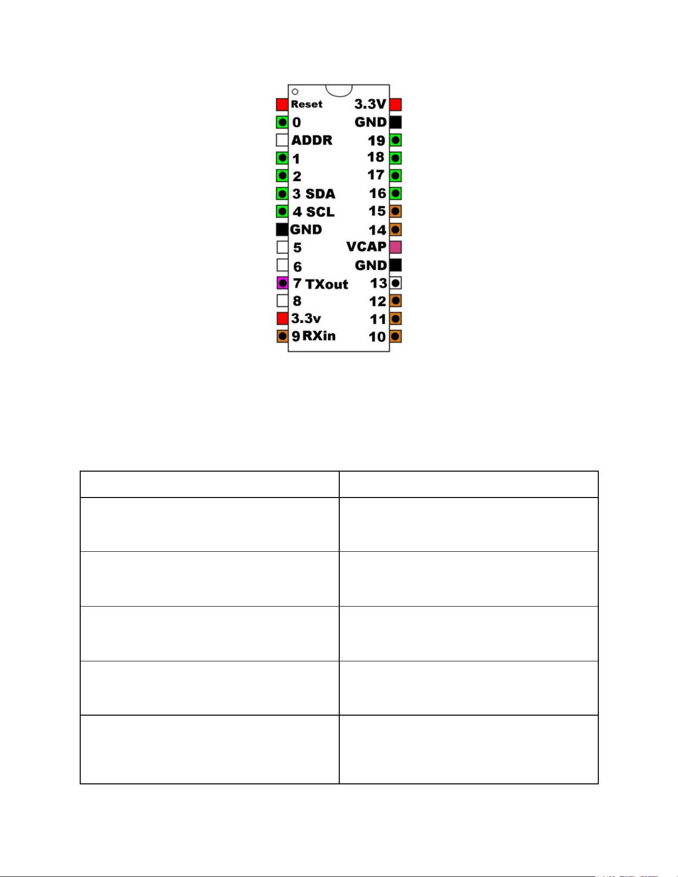
Shown above is the pinout of the Serial Wombat 18AB chip. Pins marked in Green are capable
of Analog input functions in addition to digital functions. Pins marked in brown can tolerate 5
volt digital inputs (input voltage to other pins should not exceed the chip supply voltage, typically
3.3V). Pins with circles are capable of enhanced digital functions.
The ADDR pin is used to set the I2C address or select UART operation:
ADDR Pin
Communication Interface
Open
I2C Address 0x6B. Pins 3 and 4 are used
for I2C. Pins 7 and 9 are available for
general use.
10k to GND
I2C Address 0x68. Pins 3 and 4 are used for
I2C. Pins 7 and 9 are available for general
use.
20k to GND
I2C Address 0x69. Pins 3 and 4 are used for
I2C. Pins 7 and 9 are available for general
use.
30k to GND
I2C Address 0x6A. Pins 3 and 4 are used
for I2C. Pins 7 and 9 are available for
general use.
Short to GND
UART communication at 115,200 bps, 8-N-1.
Pins 7 and 9 are used for UART
communication. Pins 3 and 4 are available
for general use. Pin 9 is a 5V tolerant pin, so
Serial Wombat 18AB Chip User Guide Page 7 of 119
V2.1.0_A

it is acceptable to receive data from a 5V host
or UART connection
The Serial Wombat 18AB chip can be powered from 3.0 to 3.3v. Lower voltages are possible,
but are not officially supported.
The I2C bus can run at any voltage between 3.0v and the Serial Wombat chip supply voltage.
External pull-up resistors are required. 2200 ohm resistors are suggested. I2C clock
frequencies up to 100kHz are supported. Preprogrammed chips are available that respond to
I2C addresses 0x6C, 0x6D, 0x6E, and 0x6F. The Serial Wombat 18AB chip utilizes I2C clock
stretching as defined in the I2C specification. Host systems controlling the Serial Wombat chip
must support clock stretching (note that the Raspberry Pi built in I2C does not support clock
stretching. The Raspberry Pi Pico Microcontroller does support clock stretching).
The Serial Wombat 18AB chip is open-source firmware running on a Microchip
PIC24FJ256GA702. See the datasheet of that part for additional electrical specifications.
The Serial Wombat 18AB utilizes an internal phase-locked-loop RC oscillator to generate its
internal clock. The nominal value of this clock is 32MHz, but may vary up to 2% based on
manufacturing variation (variation may increase beyond 2% below 0 deg. C or above 60 deg.
C). Since all timing done on the chip is based on this clock, absolute timing values such as
PWM frequency, servo pulse, pulse measurement, UART bits, etc may vary by up to 2%.
Serial Wombat 18AB Chip User Guide Page 8 of 119
V2.1.0_A

Arduino Library
An Arduino library is available that abstracts the communication protocol used by the Serial
Wombat family of chips. The examples shown in this document assume that the Arduino library
is used. The source code for the Serial Wombat Arduino library is available here:
https://github.com/BroadwellConsultingInc/SerialWombatArdLib
The library is heavily documented using Doxygen in-line comment documentation. A
compilation of this documentation is available here:
https://broadwellconsultinginc.github.io/SerialWombatArdLib/
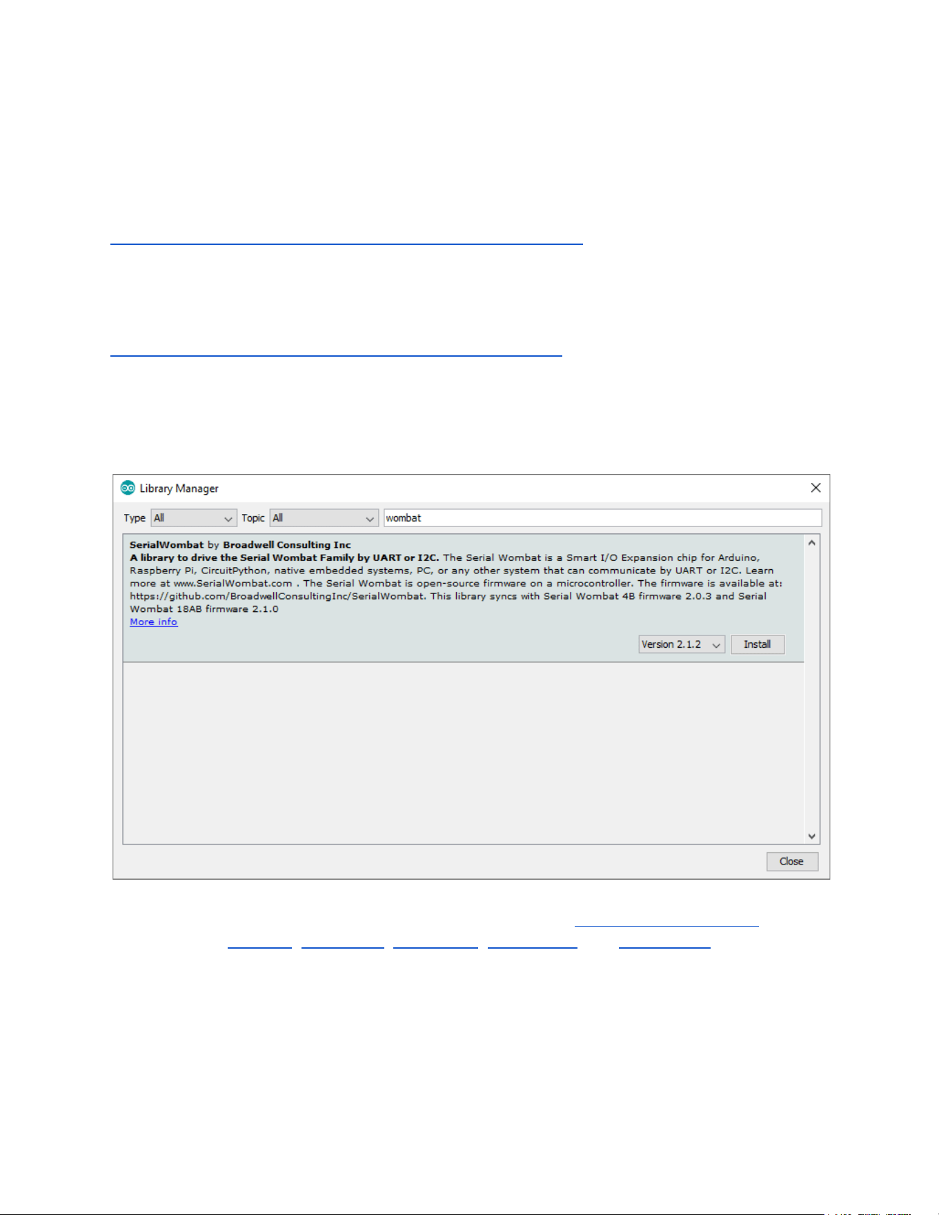
The Arduino library can be installed using the Arduino library manager:
Some Arduino based interfaces are available directly from the SerialWombatChip class in the
library, such as pinMode , digitalWrite , digitalRead , analogWrite , and analogRead . These
provide a convenient way for Arduino programmers to get started quickly with the Serial
Wombat 18AB chip. Over time, it is recommended that programmers transition to using the
native Serial Wombat interfaces shown in the examples and videos.
A getting started video which includes the library installation procedure is available on YouTube:
Serial Wombat 18AB Chip User Guide Page 10 of 119
V2.1.0_A


Python / MicroPython Library
A Python and MicroPython library is available which provides equivalent interfaces to the ones
in the Arduino library. Most videos and examples shown are in C++ for Arduino, but are easily
ported to Python.
The library is available here:
https://github.com/BroadwellConsultingInc/SerialWombatMicroPython
An introductory video is available here:
https://youtu.be/bbBO5n_Ef-I
Serial Wombat 18AB Chip User Guide Page 12 of 119
V2.1.0_A
C# library
A C# .Net llibrary is available which provides equivalent interfaces to the ones in the Arduino
library. Most videos and examples shown are in C++ for Arduino, but are easily ported to C#.
The library is available here:
https://github.com/BroadwellConsultingInc/SerialWombatCsharpLib
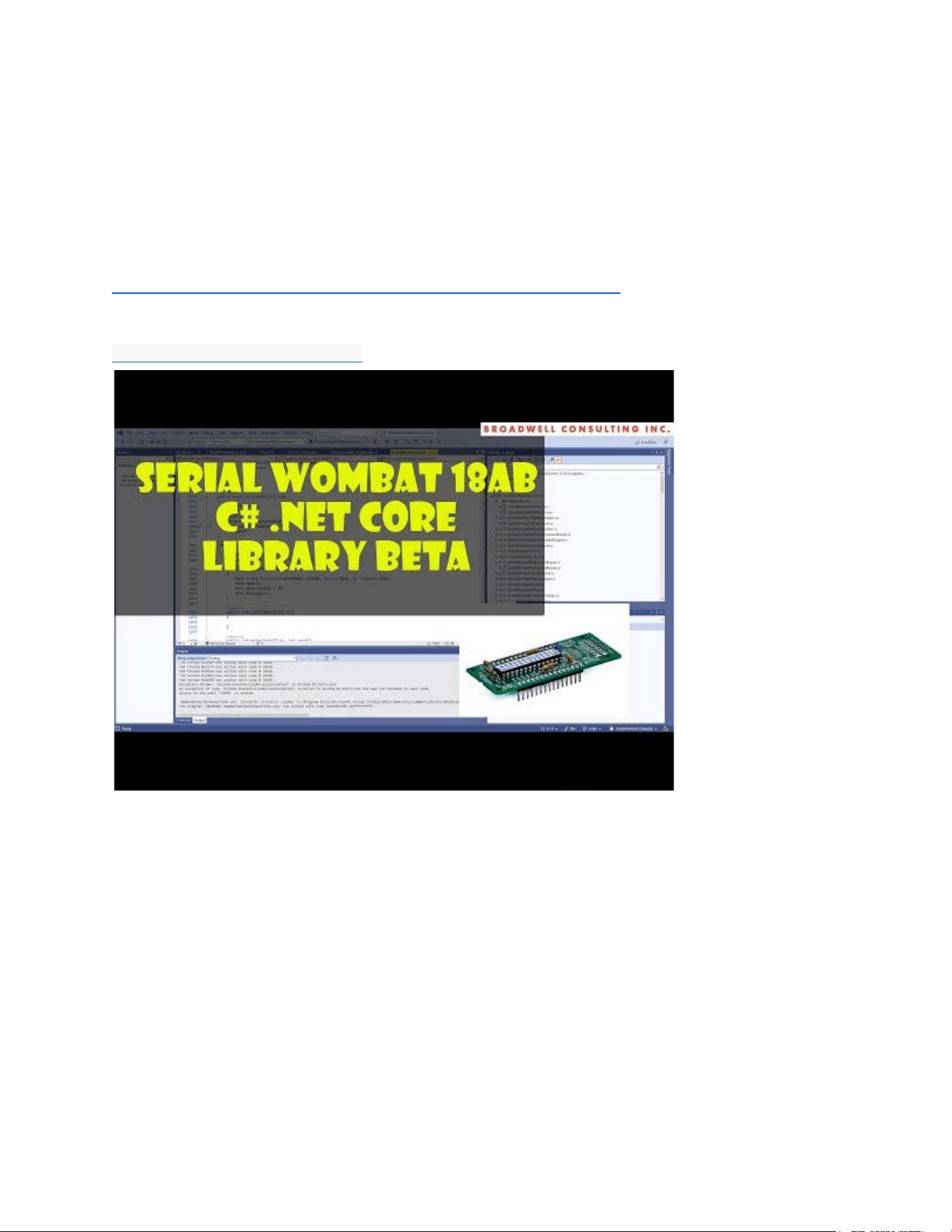
An introductory video is available here:
https://youtu.be/RgrjuJcJMmM
Serial Wombat 18AB Chip User Guide Page 13 of 119
V2.1.0_A
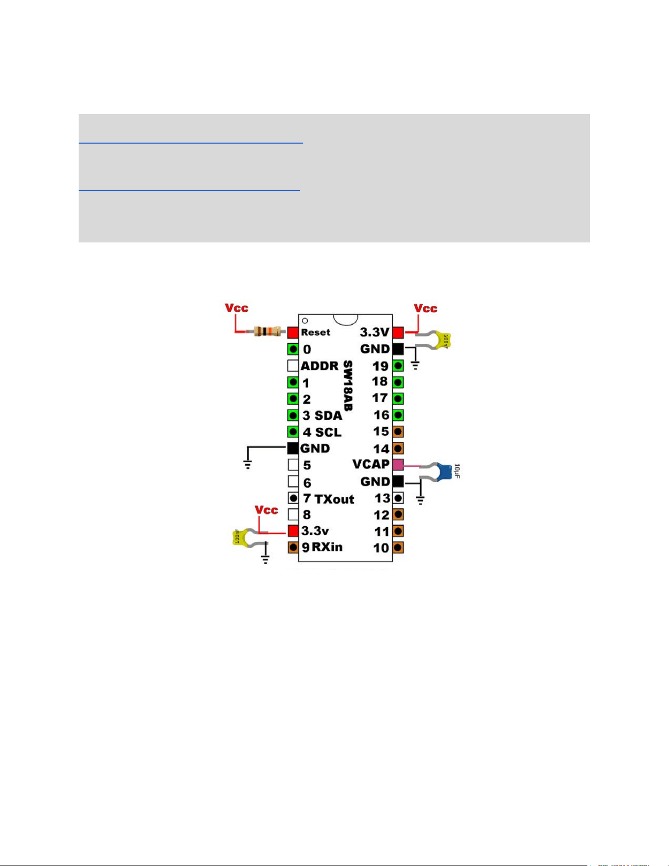
Circuit Construction
Before starting, consider subscribing to the Serial Wombat YouTube Channel:
https://www.youtube.com/@SerialWombat
and Instagram:
https://www.instagram.com/serialwombat/
When bugs are discovered or fixed or new firmware or library updates are made available a
post will be made on these platforms.
The Serial Wombat 18AB chip requires power and ground to be attached to the pins as shown
in the figure above. Additionally, 100nF ceramic decoupling capacitors must be connected
between each Vcc line and ground. A 10uF capacitor must be connected between VCAP and
ground, and a 10k resistor must be connected between the reset pin and Vcc. Appropriate
capacitors and resistors are included with the Serial Wombat 18AB kits created by Broadwell
Consulting Inc. sold on Amazon. All resistors and capacitors shown must be installed and all
connections to Vcc and Ground must be connected or the microcontroller may function
erratically
An optional connection to the ADDR pin can be used to change the address or interface to the
Serial Wombat chip as described prior in this document.
Serial Wombat 18AB Chip User Guide Page 14 of 119
V2.1.0_A
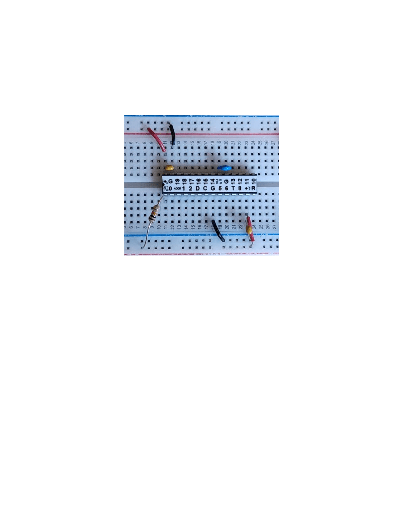
Serial Wombat 18AB kits created by Broadwell Consulting Inc. include user-applyable labels
which indicate pin functions and provide a mini-schematic of the minimal resistor and capacitor
connections. The labels are provided in a multiple-label strip. Using a rotary cutter or precision
hobby knife to cut them apart is recommended, as scissors may not provide the precision
needed to position the cuts perfectly.
I2C lines should be pulled up with appropriate resistors. Appropriate values vary with
application and clock speed. 2200 ohm pull up resistors are suggested as a starting point.
Reliance on internal Arduino or other micros’ pull ups instead of discrete resistors may cause
communication errors.
Multiple Serial Wombat Chips can be used in the same circuit as long as they (and all other I2C
devices) have unique addresses. The Serial Wombat 2-chip kit sold on Amazon includes a total
of three 10k resistors so that one may be used to set the address pin if using both chips in the
same circuit is desired.
The Serial Wombat 18AB chip requires a stable power supply to function properly. It is
suggested that loads which may cause supply instability (such as relays, servos, motors, or
other loads with large inductive or capacitive values) be powered from a separate power supply
from that used for the Serial Wombat 18AB chip, as power fluctuations caused by these loads
may trip the Serial Wombat 18AB chip’s internal low-voltage reset circuit.
Serial Wombat 18AB Chip User Guide Page 15 of 119
V2.1.0_A
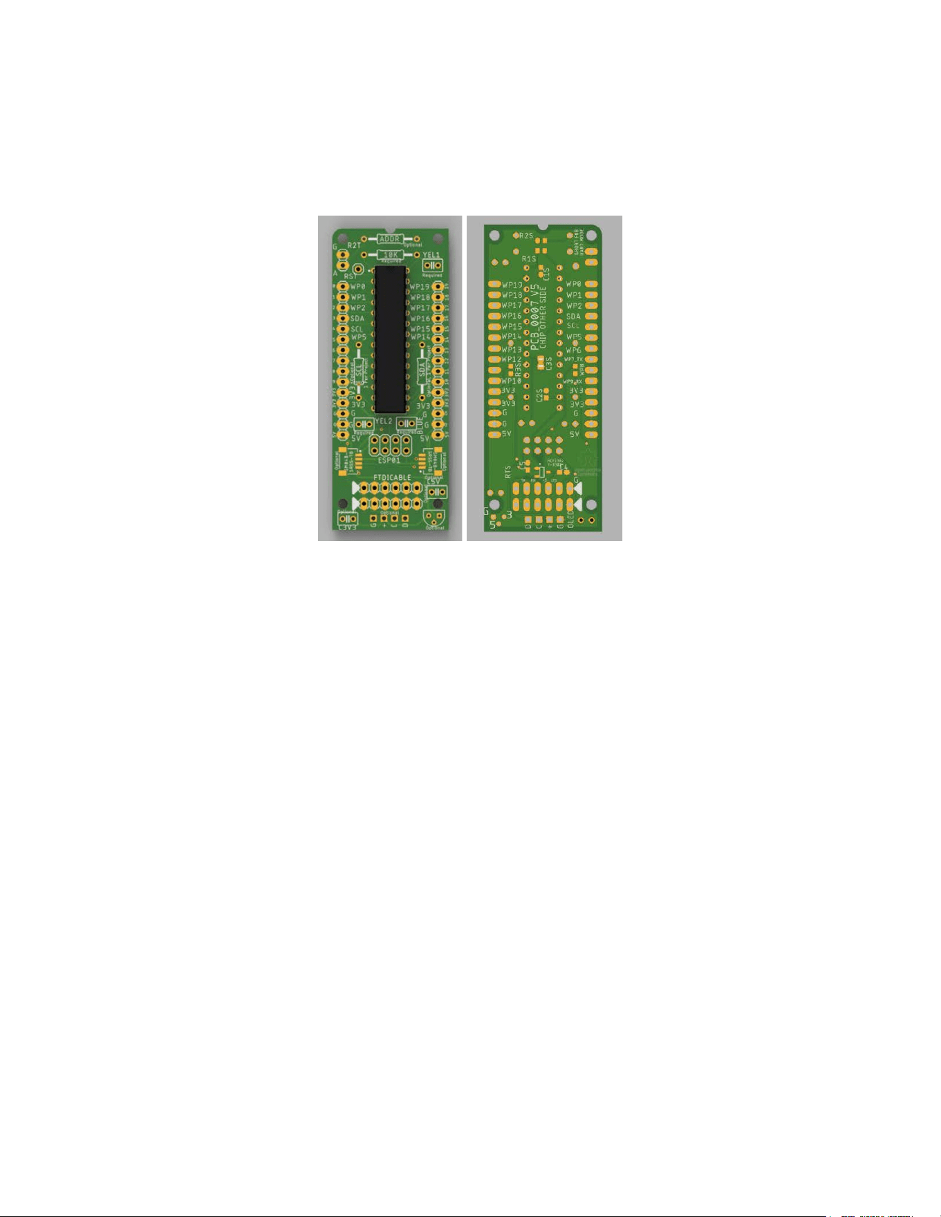
Serial Wombat 18AB PCB Board
The Serial Wombat 18AB PCB Board is designed to make the Serial Wombat 18AB chip
convenient to use alongside other hobby electronics boards. It is designed to support a number
of different use cases, including I2C connection, UART connection through an FTDI or similar
USB to UART cable and standalone IOT board when combined with an ESP-01 ESP8266
module.
Basic Assembly
The Serial Wombat 18AB PCB board is designed to be used with the components included in
the Serial Wombat 18AB kit sold on Amazon. This kit consists of:
2x Serial Wombat 18AB chips
2x Serial Wombat 18AB PCB Board
3x 10k through-hole resistors
2x 10uF through-hole capacitors (blue)
4x 100nF through-hole capacitors (yellow)
2x 2.2k through-hole resistors
Decal strip
Reference cards
The Serial Wombat 18AB PCB board is designed to be self-documenting. Components are
marked with functions on the top silkscreen. Assembly in the following order is suggested:
Serial Wombat 18AB Chip User Guide Page 16 of 119
V2.1.0_A
1. Solder the Serial Wombat 18AB chip into the PCB. Make sure that the chip is
on the right side of the board, and that the chip is in the proper orientation.
The Serial Wombat 18AB PCB board has a rounded corner which corresponds to
the #1 pin of the microcontroller (often embossed with a dot), and a notch at the
top of the board which mimics the notch in the microcontroller. When properly
assembled the chip is inserted with the notched end matching the notch in the
top of the board and the chip visible when the rounded corner of the board is in
the upper left. Do not insert the chip on the side of the board that says “CHIP
OTHER SIDE”.
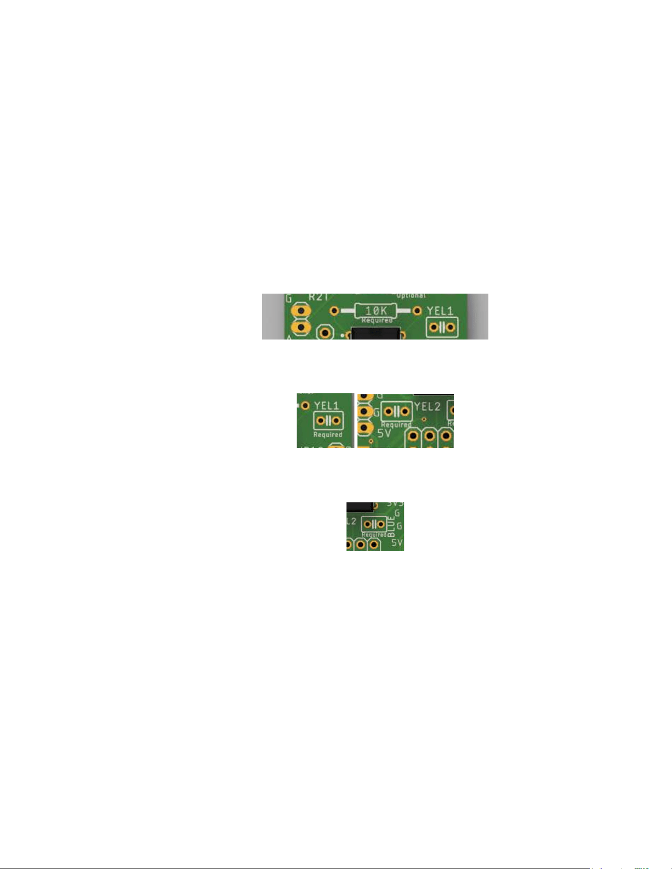
2. Solder a 10k resistor over the image of a resistor that includes the marking “10K”.
This resistor connects the reset pin to Vcc
3. Solder two yellow 100nF capacitors into the boxes marked “YEL1” and “YEL2”
4. Solder a blue 10uF capacitor into the box marked “BLUE”
5. Trim leads as necessary to make the board nice and neat
6. Apply the chip decal if desired
In this configuration the ADDR line is left floating, and will result in the chip responding to I2C
address 0x6B
Address Resistor (optional)
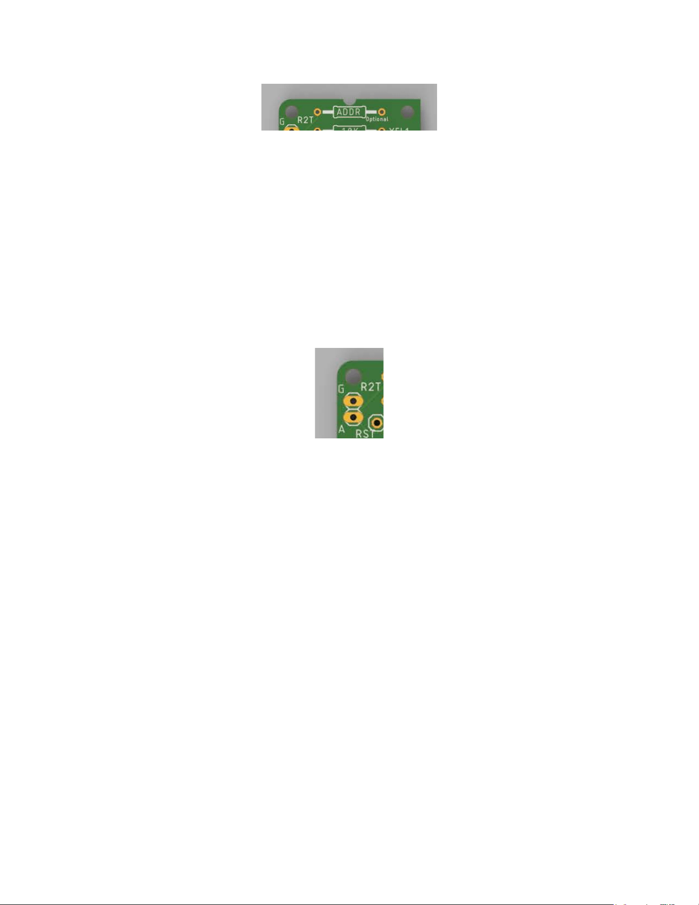
If an I2C address other than 0x6B is desired, a resistor can be soldered into the holes with the
marking “ADDR” . This set of holes connects the ADDR pin and ground.
Serial Wombat 18AB Chip User Guide Page 17 of 119
V2.1.0_A
UART Mode (optional)
The Serial Wombat 18AB will respond to UART commands rather than I2C if ADDR is
grounded. This can be achieved by using a wire in place of the ADDR resistor, or by using the
UART jumper pins
The “G” and “A” pins in the upper left corner of the board are designed to allow addition of a
2-pin 0.1” header which can be optionally closed with a jumper. In this manner it’s possible to
easily switch the Serial Wombat 18AB chip between I2C and UART mode. (A power cycle is
necessary to re-evaluate the state of the ADDR pin).
I2C Pull up resistors (optional)
The I2C bus requires pull-up resistors on SCL and SDA to function properly. If desired, these
resistors can be soldered into the Serial Wombat 18AB PCB board in the “SCL” and “SDA”
positions. The Serial Wombat 18AB kit includes two 2200 ohm resistors for this purpose. The
user should evaluate their circuit to determine the best pull up resistance for their application.
The pull up resistors typically only appear in one place across an entire application circuit
(hence the inclusion of only one set of two resistors for two boards).
5V pins and traces
The Serial Wombat 18AB PCB board includes pins marked 5V for 5 volt power. This set of
traces goes to the 5V pins on each side of the board, the FTDI connector holes, and the 3.3V
regulator locations. Operation on 5V power requires addition of an additional regulator (not
included).
Serial Wombat 18AB Chip User Guide Page 18 of 119
V2.1.0_A
5V to 3.3V LDO Regulator circuit (optional)
The Serial Wombat 18AB chip power supply should never exceed 3.6V (3.3V recommended).
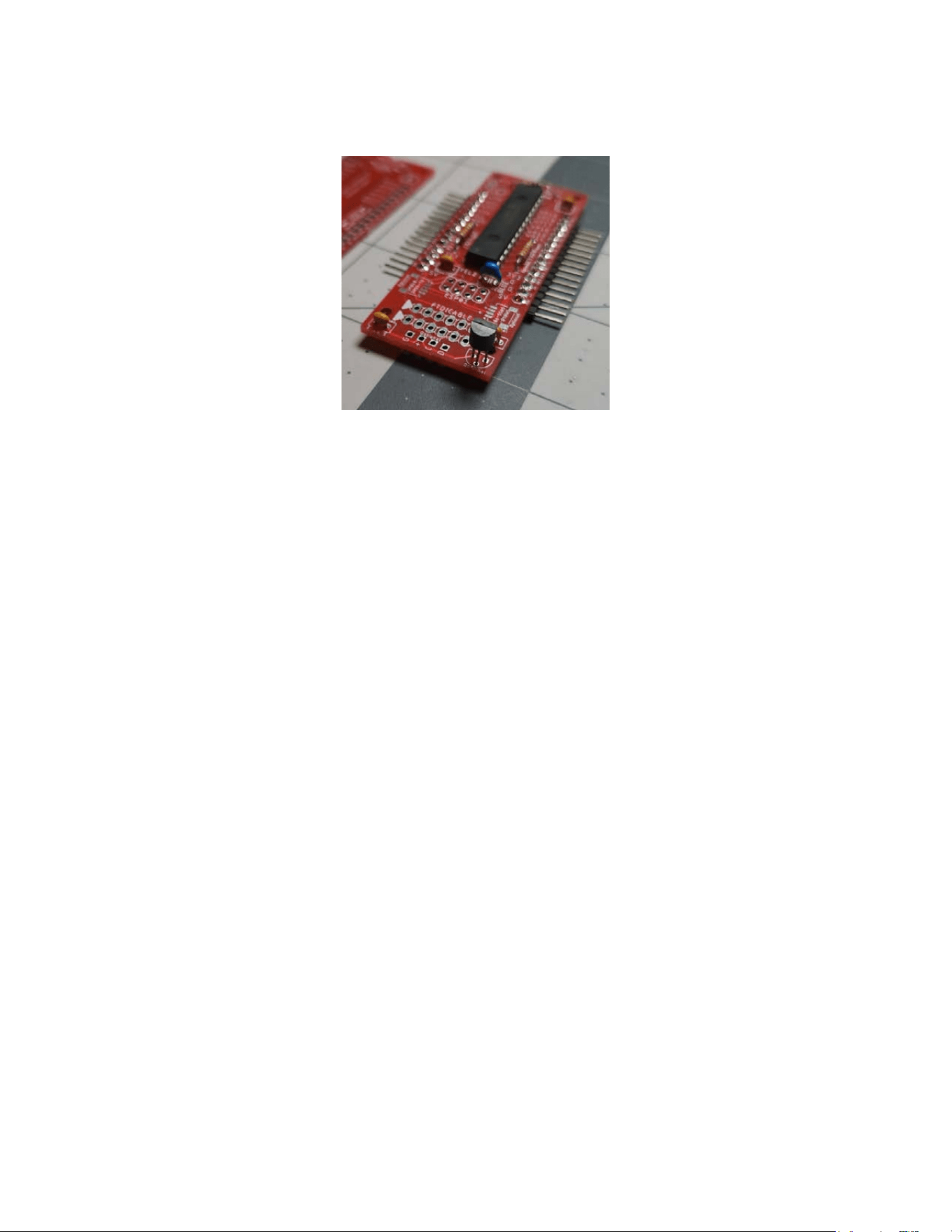
Therefore, it cannot be directly powered by a 5V supply. For convenience, the Serial Wombat
18AB PCB board incorporates options for adding a 3.3v regulator (not included). Mounting
locations are available for either a TO-92 through hole part and input and output capacitors
(C5V and C3V3, 0.1” pin spacing) or a SOT23-3 surface mount part and 0603 sized input (C4)
and output (C5) capacitors.
The surface mount layout is designed with Microchip part MCP1702-3302 in mind. Note that
the pinout for SOT23-3 regulators is not uniform across manufacturers. When using a surface
mount regulator other than the MCP1702-3302 make sure it has an identical pinout.
The throughhole option allows flexibility to use just about any TO-92 package regulator as it can
be rotated and the pins flexed to attach to the Ground, 3.3V and 5V holes in the breadboard.
Capacitor recommendations for stable operation can vary depending on regulator selected and
expected current draw. See your regulator’s datasheet for more information.
FTDI cable connector
The Serial Wombat 18AB PCB board supports connection of an FTDI or equivalent pinout USB
to UART converter. This allows the Serial Wombat 18AB chip to be easily connected to a PC or
other USB based device to allow direct data acquisition and control without the need for an
Arduino or other board.
The RX pin of the Serial Wombat 18AB chip is 5V tolerant, so both 3.3v and 5v versions of FTDI
cables can be used.
Serial Wombat 18AB Chip User Guide Page 19 of 119
V2.1.0_A
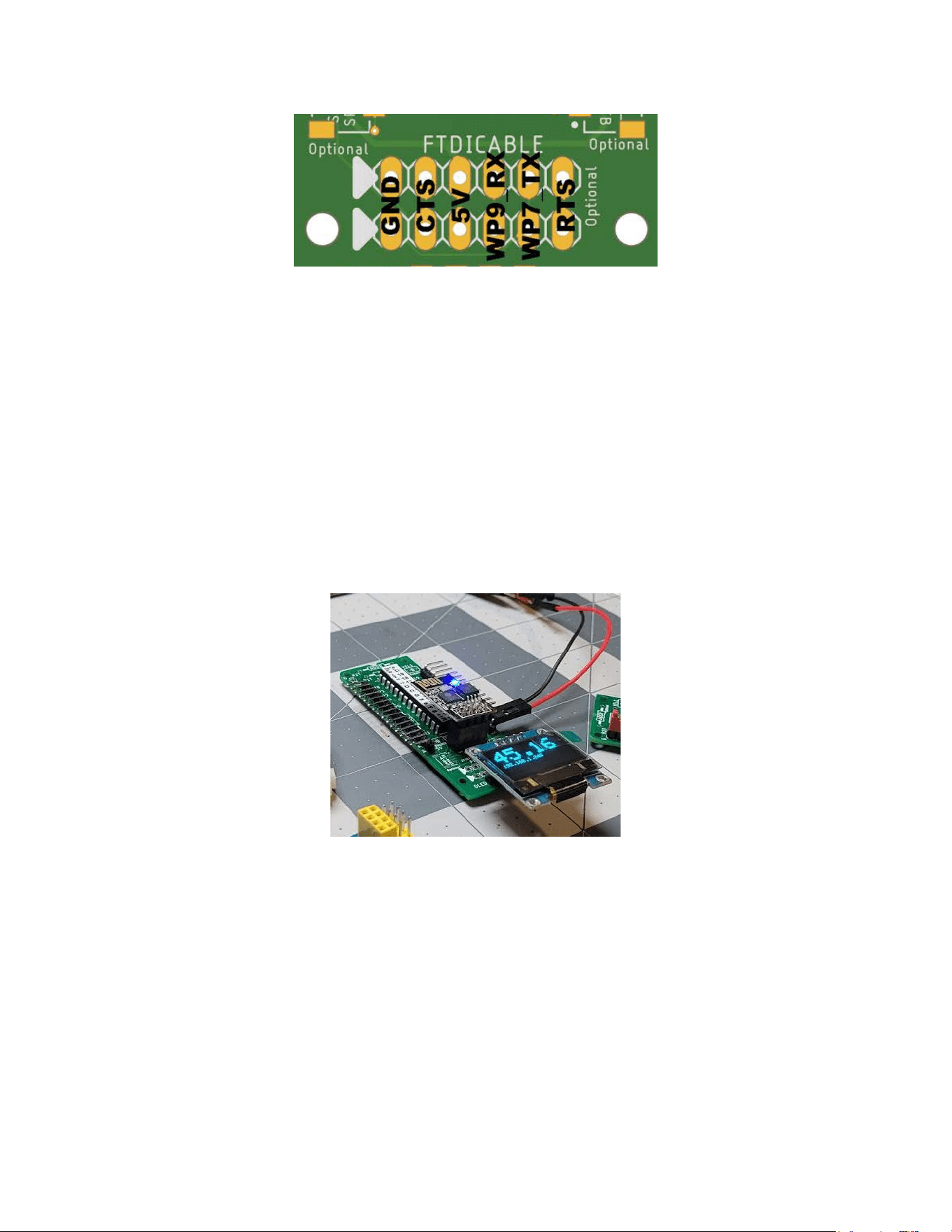
The pinout of the FTDI connector is shown above. The CTS and RTS lines are not used by the
Serial Wombat 18AB PCB board. The dual row of headers is designed to make these lines
accessible should the user want I/O lines that are controlled directly by the host rather than the
Serial Wombat 18AB chip.
The User must verify that the pinout of a cable matches the PCB footprint before connecting the
cable. Note that the WP9_RX pin is an input from the point of view of the Serial Wombat 18AB
chip. This pin may be marked TX or similar on the FTDI pinout.
ESP-01 Module connector
ESP-01 modules with their onboard ESP8266 WiFi enabled SOC provide an exceptional value
in terms of wireless connectivity and processing power for the price. However, they are lacking
with regard to I/O capability. When combined with a Serial Wombat 18AB chip, the ESP-01
becomes a very reasonably priced IOT powerhouse.
The Serial Wombat 18AB PCB board includes holes in which a 4x2 socket can be mounted
which connects an ESP-01 board to the 3.3V, ground, and I2C lines of the PCB, allowing it to
control the Serial Wombat chip.
The Serial Wombat 18AB PCB board is not designed to allow in-circuit programming of the
ESP-01 chip through the FTDI interface. The chip must be externally programmed, then placed
in the Serial Wombat 18AB PCB board.
Serial Wombat 18AB Chip User Guide Page 20 of 119
V2.1.0_A
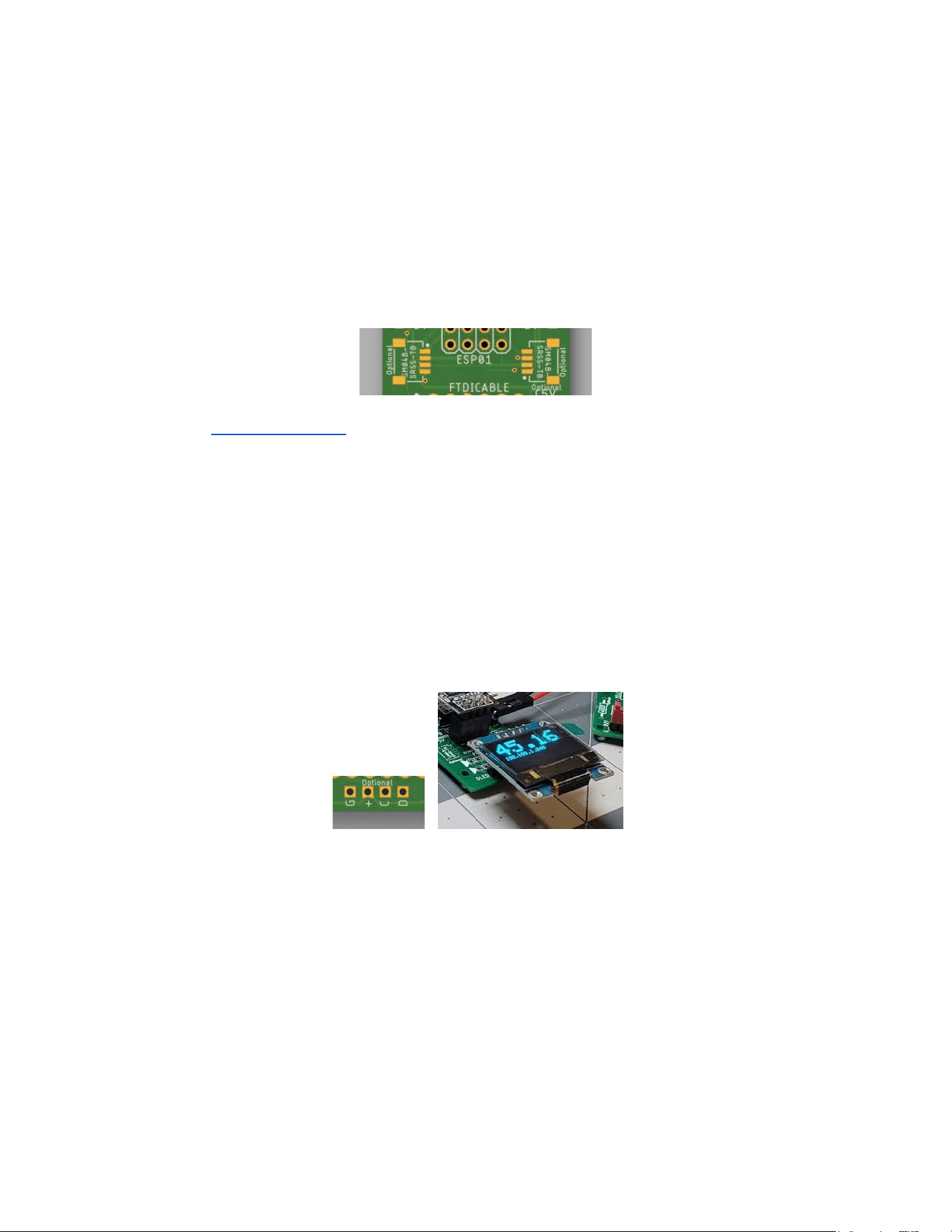
Addition of an LDO regulator (see above) allows the system to run on 5V if desired.
Qwiic/Stemma Connector Pads
Pads are available to add Qwiic/Stemma connectors (not included) to the Serial Wombat 18AB
PCB board. These connectors connect to the PCB’s I2C, 3.3V and Gnd networks.
Part number SM04B-SRSS-TB is compatible with this footprint. Generic similar parts bought
from online flea markets have also been compatible based on the author’s experience.
OLED / I2C port
A 4 pin connector is available which connects to the PCB’s I2C, 3.3V and Gnd networks. The
pinout for this connector is designed to facilitate direct connection of the most common pinout of
ubiquitous SSD1306 0.96” OLED displays to the 3.3V power and I2C bus. The Serial Wombat
firmware does not drive SSD1306 displays. The port provides a convenient way to add an
SSD1306 to the same I2C bus controlling the Serial Wombat Chip.
Surface mount Resistor / Capacitor alternate pads
Many experienced electronics practitioners prefer surface mount components to through-hole
due to the speed with which they can be manually placed. The Serial Wombat 18AB PCB board
includes alternative 0603 surface mount pads for all throughhole resistors and 100nF capacitors
on the back side of the PCB. An 0806 pad is available for the 10uF capacitor. Surface mount
components are not included with the Serial Wombat 18AB kit.
Serial Wombat 18AB Chip User Guide Page 21 of 119
V2.1.0_A
Header Pin Connectors
The Serial Wombat 18AB PCB board includes standard 0.1” holes to mount typical headers.
Straight header pins are included in the Serial Wombat 18AB kit, but other parts can be used.
For instance, the author often uses boards with right angle pins due to the ease with which
connections can be seen when shooting overhead video of a project.
RST Pin
A hole is available for adding a pin which connects to the reset line of the Serial Wombat 18AB
chip. This hole is primarily intended for use during firmware development to allow an ICD4 or
similar debugger to connect to the reset line.
Pin Modes
There are multiple pin modes which can be selected for each pin. Many pin modes can run on
any pin. Some pin modes require enhanced digital performance pins. Others require analog
capable pins. A few pin modes require specific pin numbers to be used.
Serial Wombat 18AB Chip User Guide Page 22 of 119
V2.1.0_A
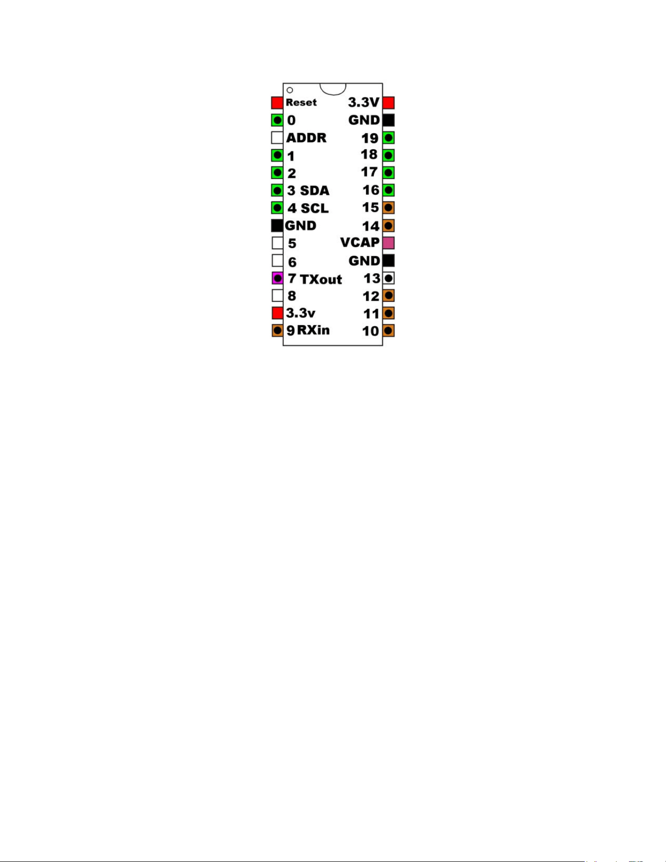
Shown above is the pinout of the Serial Wombat 18AB chip. Pins marked in Green are capable
of Analog input functions in addition to digital functions. Pins marked in brown can tolerate 5
volt digital inputs (input voltage to other pins should not exceed the chip supply voltage, typically
3.3V). Pins with circles are capable of enhanced digital performance pin modes.
Many Serial Wombat pin modes (such as Analog Input pin mode or Pulse Measurement pin
mode) provide an measurement value that varies depending upon the input. Many of these pin
modes implement the Processed Input Pin Mode set of standardized signal measurement
features for filtering, averaging, queuing, scaling, min/max tracking and outlier exclusion. See
the Processed Input Pin Mode section for more information.
Many Serial Wombat pin modes (such as PWM output pin mode or Servo output pin mode )
provide an output signal that varies depending on a value either written to that pin’s public data
value, or read from another pin’s public data value. These pins implement the Scaled Output
Pin Mode extension set of standardized output processing functions. The Scaled Output Pin
Mode extension can scale the input value, invert the input, limit the rate of change of the output,
filter the output, control the output via hysteresis, control the output via PID control, and scale
the final output. See the Scaled Output Pin Mode section for more information.
Serial Wombat 18AB Chip User Guide Page 23 of 119
V2.1.0_A
Digital GPIO Input Pin Mode (0)
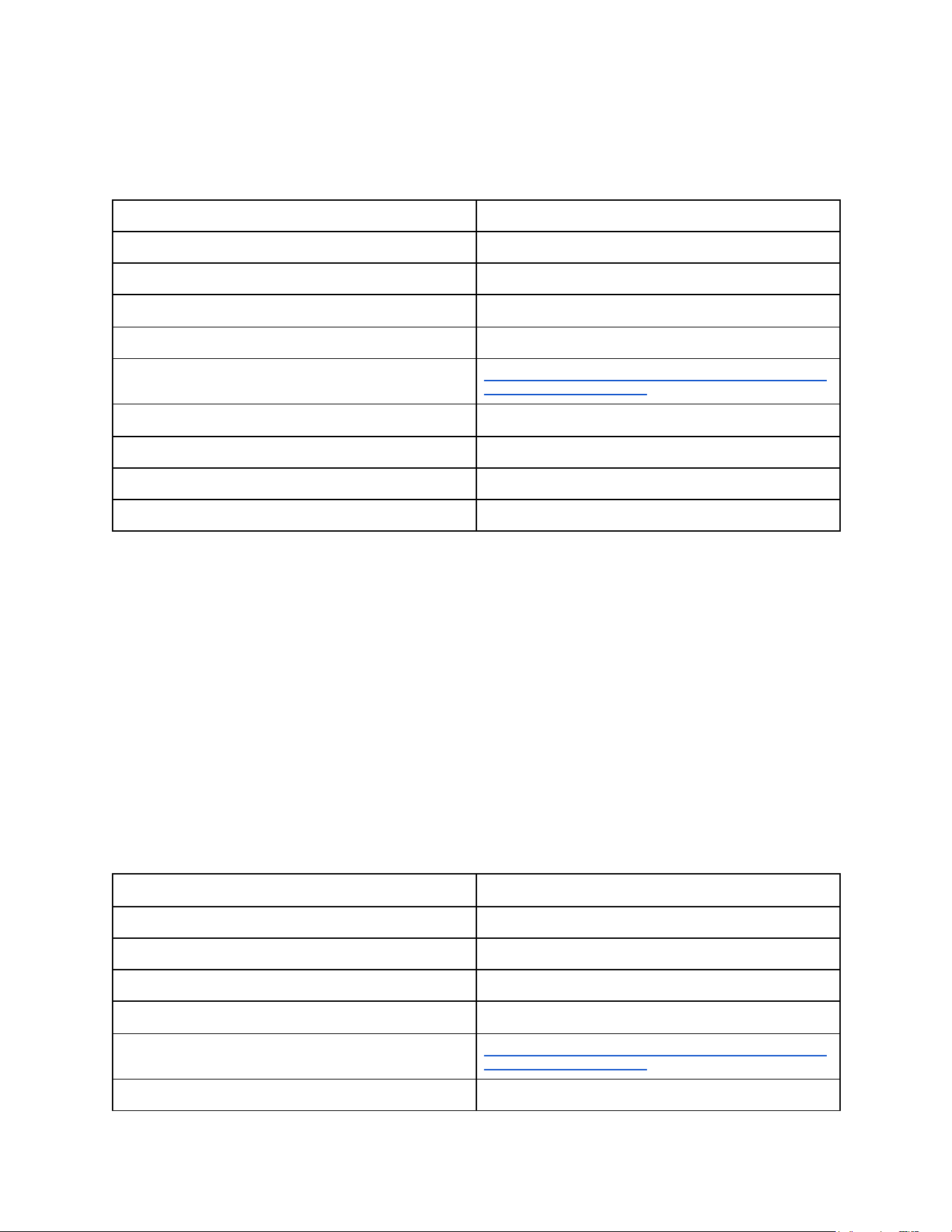
Pin Mode Name
GPIO (Input)
Pin Mode Firmware ID
0
Pin Type Required
Any
Available on Serial Wombat 4B chips
Yes
Serial Wombat 18AB Throughput consumed
Negligible
Arduino Class Documentation
https://broadwellconsultinginc.github.io/SerialWombatArdLib/cl
ass_serial_wombat_chip.html
Tutorial Video
Not Available
Implements Processed Input Functions
No
Implements Scaled Output Functions
No
Uses Timing Resource Manager resources
No
The Digital Input Pin mode allows the host to determine if the pin is logic high or logic low.
Inputs are Schmitt Trigger inputs with a low value of 0.2 x System Voltage and high value of 0.8
x System Voltage. See the PIC24FJ256GA702 datasheet for more information on logic levels.
Digital inputs can be configured to use internal pull up resistors within the chip.
When public data is accessed for a Digital Input Mode pin, the result that comes back is either 0
for low or 0xFFFF (65535) for high. This is consistent with other Serial Wombat pin modes that
scale their public data between 0 and 65535.
Digital Output Pin Mode
Pin Mode Name
GPIO (Output)
Pin Mode Firmware ID
0
Pin Type Required
Any
Available on Serial Wombat 4B chips
Yes
Serial Wombat 18AB Throughput consumed
Negligible
Arduino Class Documentation
https://broadwellconsultinginc.github.io/SerialWombatArdLib/cl
ass_serial_wombat_chip.html
Tutorial Video
Not Available
Serial Wombat 18AB Chip User Guide Page 24 of 119
V2.1.0_A
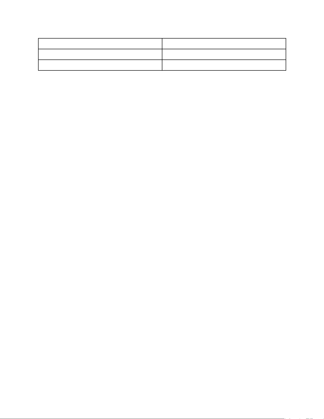
Implements Processed Input Functions
No
Implements Scaled Output Functions
No
Uses Timing Resource Manager resources
No
The Digital Output pin mode allows the host to set the pin high or low. The maximum current
sunk or sourced per pin should not exceed 25mA. The maximum current sourced by the chip
should not exceed 250mA. The maximum current sunk by the chip should not exceed 300mA.
See the PIC24FJ256GA702 datasheet for detailed electrical specifications
Serial Wombat 18AB Chip User Guide Page 25 of 119
V2.1.0_A
Analog Input Pin Mode
Pin Mode Name
Analog Input
Pin Mode Firmware ID
2
Pin Type Required
Analog Capable
Available on Serial Wombat 4B chips
Yes
Serial Wombat 18AB Throughput consumed
TBD
Arduino Class Documentation
https://broadwellconsultinginc.github.io/SerialWombatArdLib/cl
ass_serial_wombat_analog_input__18_a_b.html
Tutorial Video
https://www.youtube.com/watch?v=_EKlrEVaEhg (Serial
Wombat 4B chip equivalent pin mode)
Implements Processed Input Functions
Yes
Implements Scaled Output Functions
No
Requires Timing Resource Manager resources
No
Functions if Timing Resource Manager resources are
unavailable
N/A
The Serial Wombat 18AB chip can measure up to 9 separate analog inputs in UART mode or 7
separate analog inputs in I2C mode, plus its own source voltage.
The Serial Wombat 18AB firmware makes a new 12-bit measurement every 1mS. The pin state
machine implements the Processed Input Pin Mode set of standardized signal measurement
features for filtering, averaging, queuing, scaling, min/max tracking and outlier exclusion. See
the Processed Input Pin Mode section for more information.
Serial Wombat analog measurements are ratiometric, ranging from 0 to 65535 where 0 means
that the incoming voltage was equal (within the 12-bit resolution) to ground, and 65535 means
that the incoming voltage was equal (within the 12-bit resolution) to the Serial Wombat chip’s
source voltage. Because 0-65535 represents a 16 bits of resolution but the Serial Wombat
18AB chip’s A/D unit is only 12 bits, values will exhibit quantization in 16 count increments (e.g.
the raw results can be 0, 16, 32, 48, 64, 32768, 51216 … but not 15, 45, 68, 32784, 51213,
etc). In the case that the A/D reports a maximum value of 65520, this value is reported as
65535 (to be consistent with using that value to represent positive maximum scale).
An Arduino equivalent function .readAnalog() can be called directly from a Serial Wombat Chip
instance. This function initializes a pin as an analog input, takes a reading, and scales it to a
value between 0 and 1023 to correspond with the behavior of the Arduino Uno.
Serial Wombat 18AB Chip User Guide Page 26 of 119
V2.1.0_A
The Serial Wombat 18AB chip is capable of measuring an internal reference voltage which in
turn can be used to infer the system voltage. The Arduino library has functions to retrieve the
system voltage, as well as output A/D conversions in mV rather than counts using the measured
system voltage as the high value for the ratiometric conversion.
Input impedance for A/D inputs should be 5 kOhm or less. See the PIC24FJ256GA702
datasheet for additional performance and electrical characteristics of the A/D converter circuit.
A video tutorial of the Serial Wombat 4B chip’s analog capabilities, which are similar but less
capable than the Serial Wombat 18AB’s is available here:
https://www.youtube.com/watch?v=_EKlrEVaEhg
The Arduino class is documented here:
https://broadwellconsultinginc.github.io/SerialWombatArdLib/class_serial_wombat_analog_input
.html
Here’s an Arduino example of the using 3 pins to monitor two potentiometers and a TMP32
temperature sensor using the Analog Input pin mode:
#include < SerialWombat . h >
SerialWombatChip sw6B; //Declare a Serial Wombat
SerialWombatAnalogInput leftPot(sw6B); //5k linear Pot
SerialWombatAnalogInput rightPot(sw6B); //5k linear Pot
SerialWombatAnalogInput temperatureSensor(sw6B);
Serial Wombat 18AB Chip User Guide Page 27 of 119
V2.1.0_A

// This example is explained in a video tutorial at: https://youtu.be/_EKlrEVaEhg
void setup () {
// put your setup code here, to run once:
{ //I2C Initialization
Wire . begin ();
sw6B . begin ( Wire , 0x6B); //Initialize the Serial Wombat library to use the primary I2C port,
SerialWombat is address 6C
}
leftPot . begin (0);
rightPot . begin (1);
temperatureSensor . begin (2 , 64 , 65417); // Wombat pin 2, average 64 samples, .5 Hz Low Pass filter
Serial . begin (115200);
}
void loop () {
Serial . print ( "Source V: " );
uint16_t supplyVoltage
= sw6C . readSupplyVoltage_mV ();
Serial . print (supplyVoltage );
Serial . print ( "mV Left Pot: " );
Serial . print (leftPot . readCounts ());
Serial . print ( " " );
uint16_t leftVoltage = leftPot . readVoltage_mV ();
Serial . print (leftVoltage);
Serial . print ( "mV Right Pot:" );
Serial . print (rightPot . readCounts ());
Serial . print ( " " );
uint16_t rightVoltage = rightPot . readVoltage_mV ();
Serial . print (rightVoltage);
Serial . print ( "mV T:" );
Serial . print (temperatureSensor . readCounts ());
Serial . print ( " " );
Serial . print (temperatureSensor . readVoltage_mV ());
Serial . print ( "mV " );
float tempSensor_mV = temperatureSensor . readAveraged_mV ();
//See datasheet for TMP36 Temperature sensor for conversion
float temperature = (tempSensor_mV -
750) / 10.0 + 25;
Serial . print (temperature);
Serial . print ( " deg C " );
Serial . println ();
delay (200);
}
Serial Wombat 18AB Chip User Guide Page 28 of 119
V2.1.0_A
Servo Output Pin Mode
Pin Mode Name
Servo Output
Pin Mode Firmware ID
3
Pin Type Required
Any (degraded resolution on pins that are not enhanced digital
performance)
Available on Serial Wombat 4B chips
Yes
Serial Wombat 18AB Throughput consumed
TBD
Arduino Class Documentation
https://broadwellconsultinginc.github.io/SerialWombatArdLib/class_serial
_wombat_servo__18_a_b.html
Tutorial Video
https://www.youtube.com/watch?v=WiciAtS1ng0 (Serial Wombat 4B
chip equivalent pin mode)
Implements Processed Input Functions
No
Implements Scaled Output Functions
Yes
Requires Timing Resource Manager resources
Yes
Functions if Timing Resource Manager resources are
unavailable
Resolution of pulses degrades from sub-microsecond to 17uS.
The Serial Wombat 18AB chip can drive up to 18 standard RC servos simultaneously. Up to 6
servos can be driven with sub-microsecond precision, and the remaining 12 with 17uS
precision. What pins are what precision depends on the order in which they are initialized. See
the Timing Resource Manager section for more information.
The Servo pin mode outputs a pulse every 20mS. The minimum and maximum pulse lengths
are specified when the pin mode is initialized (544uS and 2400uS maximum by default).
The host then provides a 16 bit value between 0 and 65535 which scales the pulse between
minimum and maximum length.
A reverse option can be specified at initialization which causes 0 to generate a maximum length
pulse, and 65535 to generate a minimum length pulse. This is useful to make operation intuitive
in cases where the servo moves opposite of what “feels” like the natural direction for an
increasing value.
The Serial Wombat 18AB can position a servo based either on a position commanded by the
host, or by constantly adjusting the servo input based on another Serial Wombat 18AB pin’s 16
bit Public Data.
The Serial Wombat 18AB Servo pin mode implements the Scaled Output Pin Mode extension
set of standardized output processing functions. This is useful when adjusting the Servo’s
Serial Wombat 18AB Chip User Guide Page 29 of 119
V2.1.0_A
position based on another pin’s Public Data value. The Scaled Output Pin Mode extension can
scale the input value, invert the input, limit the rate of change of the output, filter the output,
control the output via hysteresis, control the output via PID control, and scale the final output.
See the Scaled Output Pin Mode section for more information.
The Arduino class which wraps this functionality also provides an Arduino compatible interface
which takes a value of 0 to 180 rather than 0 to 65535 to scale between minimum and maximum
pulses.
A video demonstrating the Servo pin mode on the Serial Wombat 4B is available here:
https://www.youtube.com/watch?v=WiciAtS1ng0
Here’s an Arduino example of the Servo pin mode from the Arduino library examples which
declares two servos and controls one using the 16 bit interface, and the other using the Arduino
compatible interface.
#include < SerialWombat . h >
SerialWombatChip sw; //Declare a Serial Wombat chip
SerialWombatServo ContinuousServo(sw); // Declare a Servo on pin 2 of Serial Wombat sw
Serial Wombat 18AB Chip User Guide Page 30 of 119
V2.1.0_A

SerialWombatServo StandardServo(sw); // Declare a Servo on pin 3 of Serial Wombat sw
// A video tutorial is available which explains this example in detail at:
https://youtu.be/WiciAtS1ng0
void setup () {
{ //I2C Initialization
Wire . begin ();
sw . begin ( Wire , 0x6B); //Initialize the Serial Wombat library to use the primary I2C port,
This SerialWombat's address is 6B.
}
ContinuousServo . attach (2 , 500 , 2500 , true ); // Initialize a servo on pin 2, 500uS minimum pulse,
2500 us Maximum pulse, reversed
StandardServo . attach (0); // Initialize a servo on pin 0 using Arduino equivalent default
values
}
void loop () {
// put your main code here, to run repeatedly:
ContinuousServo . write (30); // Takes a number from 0 to 180
StandardServo . write16bit (5500); // Takes a number from 0 to 65535: Higher resolution
delay (5000);
ContinuousServo . write (140);
StandardServo . write16bit (50000);
delay (5000);
}
Serial Wombat 18AB Chip User Guide Page 31 of 119
V2.1.0_A
Throughput Consumer Pin Mode
Pin Mode Name
Throughput Consumer
Pin Mode Firmware ID
4
Pin Type Required
Any
Available on Serial Wombat 4B chips
No
Serial Wombat 18AB Throughput consumed
Varies with configuration
Arduino Class Documentation
https://broadwellconsultinginc.github.io/SerialWombatArdLib/class_serial
_wombat_throughput_consumer.html
Tutorial Video
N/A
Implements Processed Input Functions
No
Implements Scaled Output Functions
No
Requires Timing Resource Manager resources
No
Functions if Timing Resource Manager resources are
unavailable
N/A
The Throughput Consumer Pin mode exists primarily for firmware testing. It can be configured
to waste a specified amount of time out of each 1mS frame (see the section on Serial Wombat
18AB Firmware Architecture). This allows simulation of scenarios where the various selected
pin modes consume CPU time. The pin mode allows up to 16 different times to be configured
in successive frames. The pin is low except when the pin mode is consuming CPU time, during
which it is high. This allows viewing on a logic analyzer of when and how much CPU time is
being wasted by the pin mode in each frame. See the section on Serial Wombat 18AB
Throughput Management for more information.
Serial Wombat 18AB Chip User Guide Page 32 of 119
V2.1.0_A
Quadrature Encoder Input Pin Mode
Pin Mode Name
Quadrature Encoder
Pin Mode Firmware ID
5
Pin Type Required
Any
Available on Serial Wombat 4B chips
Yes
Serial Wombat 18AB Throughput consumed
TBD
Arduino Class Documentation
https://broadwellconsultinginc.github.io/SerialWombatArdLib/class_serial
_wombat_quad_enc.html
Tutorial Video
https://youtu.be/_wO8cOada3w (Serial Wombat 4B chip Equivalent Pin
Mode)
Implements Processed Input Functions
No
Implements Scaled Output Functions
No
Requires Timing Resource Manager resources
No
Functions if Timing Resource Manager resources are
unavailable
N/A
The Serial Wombat Quadrature Encoder Pin Mode configures two pins on the Serial Wombat
chip to work together to read quadrature encoder inputs.
By offloading the reading of an encoder to the Serial Wombat chip, it makes it easy for the host
to track multiple encoders at once. The host need only periodically retrieve the net change in
rotary encoder position from the Serial Wombat chip rather than monitoring for every signal
change.
The Serial Wombat Quadrature Encoder Pin Mode is capable of running in either polled or DMA
driven modes.
Polled mode is recommended for manual inputs such as rotary encoder knobs. It polls at 1 kHz
which is fast enough for most applications.
DMA driven mode on the Serial Wombat 18AB samples at 57600 Hz rather than 1 kHz and can
decode pulse inputs from rapidly spinning encoders, but using DMA mode consumes much
more CPU throughput on the Serial Wombat 18AB chip. When using DMA mode both pins
must be on the same microcontroller port.
The Serial Wombat Quadrature Encoder Pin Mode can make use of the Serial Wombat chip's
built in pull-up resistors to make connecting a rotary encoder knob very simple. Debouncing is
available which prevents additional transitions from being measured for a specified number of
mS after a transition.
Serial Wombat 18AB Chip User Guide Page 33 of 119
V2.1.0_A
Rotational direction measurement can be changed by switching the "pin" and "second pin"
parameters in the begin call.
The reported position can be changed on low to high transitions of "pin", high to low transitions,
or both transitions. This allows knobs that make and break connection on each click/detent and
knobs that either make or break connection on each detent to report one change per detent to
the host.
The default mode for simple initialization is to measure both, which will result in 2 increments
per detent for encoders that make and break connection on each detent.
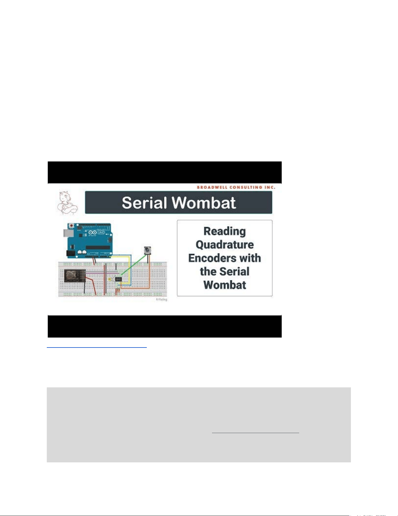
A video tutorial of the Serial Wombat 4B chip’s Quadrature Encoder capabilities (Serial Wombat
18AB chips work similarly) is available here:
https://youtu.be/_wO8cOada3w
The following code shows Initializing two Quadrature/Rotary encoders on a Serial Wombat chip
and reading them periodically.
#include < SerialWombat . h >
SerialWombatChip sw6C; //Declare a Serial Wombat chip
SerialWombatQuadEnc qeBasic(sw6C);
SerialWombatQuadEnc qeWithPullUps(sw6C);
// This example is explained in a video tutorial at: https://youtu.be/_wO8cOada3w
void setup () {
// put your setup code here, to run once:
Serial Wombat 18AB Chip User Guide Page 34 of 119
V2.1.0_A
{ //I2C Initialization
Wire . begin ();
sw6C . begin ( Wire , 0x6C); //Initialize the Serial Wombat library to use the primary I2C port,
SerialWombat is address 6C
}
qeBasic . begin (0 , 1); // Initialize a QE on pins 0 and 1
qeWithPullUps . begin (2 , 3); // Initialize a QE on pins 2 and 3
Serial . begin (115200);
}
void loop () {
Serial . print (qeBasic . read ());
Serial . print ( " " );
Serial . print
(qeWithPullUps . read ());
Serial . println ();
delay (50);
}
Watchdog Pin Mode
Pin Mode Name
Watchdog
Pin Mode Firmware ID
7
Pin Type Required
Any
Available on Serial Wombat 4B chips
Yes
Serial Wombat 18AB Throughput consumed
TBD
Arduino Class Documentation
https://broadwellconsultinginc.github.io/SerialWombatArdLib/class_serial
_wombat_watchdog.html
Tutorial Video
https://youtu.be/fIObjmHmprY (Serial Wombat 4B chip Equivalent Pin
Mode)
Implements Processed Input Functions
No
Implements Scaled Output Functions
No
Requires Timing Resource Manager resources
No
Functions if Timing Resource Manager resources are
unavailable
N/A
The Serial Wombat Watchdog Pin Mode is designed to improve system reliability in case of
communications loss with the host device. This may be because the communications lines are
no longer functional (e.g. I2C bus locked up) or the host ceases to communicate (Such as when
an Arduino malfunctions due to issues allocating string memory).
Once enabled, the Serial Wombat Watchdog will change its output and optionally other Serial
Wombat outputs to predefined states and optionally reset the Serial Wombat itself if a new
Watchdog feeding message isn't received within a period of time specified in the initialization.
Serial Wombat 18AB Chip User Guide Page 35 of 119
V2.1.0_A
The output can be used to reset the host, for instance when connected to an Arduino reset pin,
or used to shut off an output. For instance, a motor controlled by a SerialWombatWatchdog pin
could be configured to turn off if the host doesn't periodically feed the watchdog.
A video tutorial for the Serial Wombat 4B chip (Serial Wombat 18AB chips work similarly) is
available:
https://youtu.be/fIObjmHmprY
Here’s an example where pin 2 of a Serial Wombat 18AB chip is tied to the reset pin of an
Arduino. The Arduino chip is designed to malfunction, leaving it stuck in a loop. Eventually, the
Serial Wombat 18AB pin will pull the Arduino’s reset pin due to not being serviced.
#include < SerialWombat . h >
SerialWombatChip sw; //Declare a Serial Wombat chip
SerialWombatWatchdog Watchdog(sw); // Declare a Watchdog pin
// A video tutorial for this example is available at: https://youtu.be/fIObjmHmprY
void setup () {
{ //I2C Initialization
Wire . begin ();
sw . begin ( Wire , 0x6B); //Initialize the Serial Wombat library to use the primary I2C port,
This SerialWombat's address is 6B.
}
Watchdog . begin (2 , // Start the watchdog on pin 2.
SW_INPUT , // Make the pin Input for normal operation
SW_LOW , // Make the pin go low on timeout
10000 , // Timeout is 10 seconds
Serial Wombat 18AB Chip User Guide Page 36 of 119
V2.1.0_A

false ); // The Serial Wombat won't self-reset on
timeout
Serial . begin (115200);
Serial . println ();
Serial . println ( "Setup Complete." );
}
// This flawed routine works well if A is a multiple of B, but
// acts badly otherwise because quotient is unsigned and rolls
// back to a big number if the subtraction goes negative.
// Some values, such as 60 / 7 eventually end up returning a
// (wrong) result as the rollover(s) end up eventually
// giving a number that is a multiple of B.
// others such as 60 / 8 stay trapped in the loop forever.
uint8_t DivideAByB( uint8_t A , uint8_t B)
{
uint8_t C = 0;
while (A > 0)
{
A = A - B;
++ C;
}
return C;
}
int x =
1;
void loop () {
// put your main code here, to run repeatedly:
Serial . println ();
Serial . print ( "60 / " );
Serial . print (x) ;
Serial . print ( " = " );
Serial . println (DivideAByB(60 , x));
++ x;
Watchdog . updateResetCountdown (10000); // Reset the watchdog clock to 10 seconds
delay (1000);
}
Serial Wombat 18AB Chip User Guide Page 37 of 119
V2.1.0_A
Protected Output Pin Mode
Pin Mode Name
Protected Output
Pin Mode Firmware ID
8
Pin Type Required
Any
Available on Serial Wombat 4B chips
Yes
Serial Wombat 18AB Throughput consumed
TBD
Arduino Class Documentation
https://broadwellconsultinginc.github.io/SerialWombatArdLib/class_serial
_wombat_protected_output.html
Tutorial Video
https://youtu.be/p8CO04C1q_Y (Serial Wombat 4B chip Equivalent Pin
Mode)
Implements Processed Input Functions
No
Implements Scaled Output Functions
No
Requires Timing Resource Manager resources
No
Functions if Timing Resource Manager resources are
unavailable
N/A
The Serial Wombat Protected Output pin mode is assigned to a Serial Wombat output pin. It
monitors another previously configured pin's public data, such as a digital I/O value or an
Analog input. If the monitored value does not meet expectations, then the protected pin
changes values to a configured state. This allows the Serial Wombat chip to constantly
verify a condition without the need for constant polling from the host device.
Warning: The Serial Wombat 18AB chip’s Protected Output Pin Mode is intended to help
prevent accidental damage to hobby circuitry. The Serial Wombat chip and its associated
libraries are not designed for use in Safety Critical applications. The Serial Wombat chip should
not be used in situations where a malfunction or design defect could result in damage to
property, economic loss, or harm to living people or creatures.
The period of time that a mismatch must occur before going to the safe state
is configurable.
A video tutorial of the Serial Wombat 18AB chip’s protected output capabilities is available here:
https://youtu.be/p8CO04C1q_Y
Serial Wombat 18AB Chip User Guide Page 38 of 119
V2.1.0_A
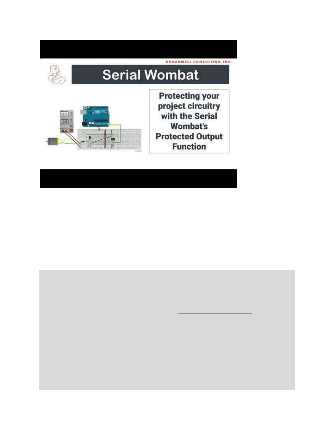
The Arduino class is documented here:
https://broadwellconsultinginc.github.io/SerialWombatArdLib/class_serial_wombat_protected_ou
tput.html
Here’s an Arduino example where pin 0 is configured to monitor pin 1, which is configured as an
analog input. The protected output pin is configured to be high unless pin one is higher than
8000 for 10 mS, in which case it latches low until reset by the host.
#include < SerialWombat . h >
SerialWombatChip sw; //Declare a Serial Wombat chip
SerialWombatProtectedOutput swpo(sw);
SerialWombatAnalogInput Feedback(sw);
// This example is explained in a video tutorial at: https://youtu.be/p8CO04C1q_Y
void setup () {
// put your setup code here, to run once:
Serial . begin (115200); //Initialize Arduino Serial Port for terminal use
{ //I2C Initialization
Wire . begin ();
sw . begin ( Wire , 0x6C); //Initialize the Serial Wombat library to use the primary I2C port,
SerialWombat is address 6C.
}
swpo . begin (0 , 1); // Controlling pin 0. Feedback from pin 1.
Serial Wombat 18AB Chip User Guide Page 39 of 119
V2.1.0_A

Feedback . begin (1); // Begin analog reading on pin 1
}
int i;
void loop () {
if (swpo . isInSafeState ())
{
Serial . println ( "Protected Output Fault Detected, Output set to Safe State!" );
}
if (i & 0x01)
{
swpo . configure ( PO_FAULT_IF_FEEDBACK_GREATER_THAN_EXPECTED , 8000 , 10 , SW_HIGH , SW_LOW );
Serial . println ( "On" );
}
else
{
swpo . digitalWrite (
LOW );
Serial . println ( "Off" );
}
delay (100);
Serial . print ( "counts at drain: " );
Serial . println (Feedback . readCounts ());
Serial . print (Feedback . readVoltage_mV ());
Serial . println ( " mV" );
Serial . println ();
delay (3000);
++ i;
}
Serial Wombat 18AB Chip User Guide Page 40 of 119
V2.1.0_A
Debounced Input Pin Mode
Pin Mode Name
Debounced Input
Pin Mode Firmware ID
10
Pin Type Required
Any
Available on Serial Wombat 4B chips
Yes
Serial Wombat 18AB Throughput consumed
TBD
Arduino Class Documentation
https://broadwellconsultinginc.github.io/SerialWombatArdLib/class_serial
_wombat_debounced_input.html
Tutorial Video
https://www.youtube.com/watch?v=R1KM0J2Ug-M (Serial Wombat 4B
chip Equivalent Pin Mode)
Implements Processed Input Functions
No
Implements Scaled Output Functions
No
Requires Timing Resource Manager resources
No
Functions if Timing Resource Manager resources are
unavailable
N/A
Debounced Input pin mode is designed to facilitate button and other switch style inputs which
may oscillate before settling to a constant value.
The Debounced Input pin mode monitors an input pin 1000 times per second and reports back a
value only after it has stabilized for a specified period of time.
The Debounced Input pin mode also counts debounced transitions and records how long in
milliseconds the pin has been in the present state. This allows easy creation of user interfaces
or pulse counters without the need to constantly query the Serial Wombat chip.
Serial Wombat 18AB Chip User Guide Page 41 of 119
V2.1.0_A
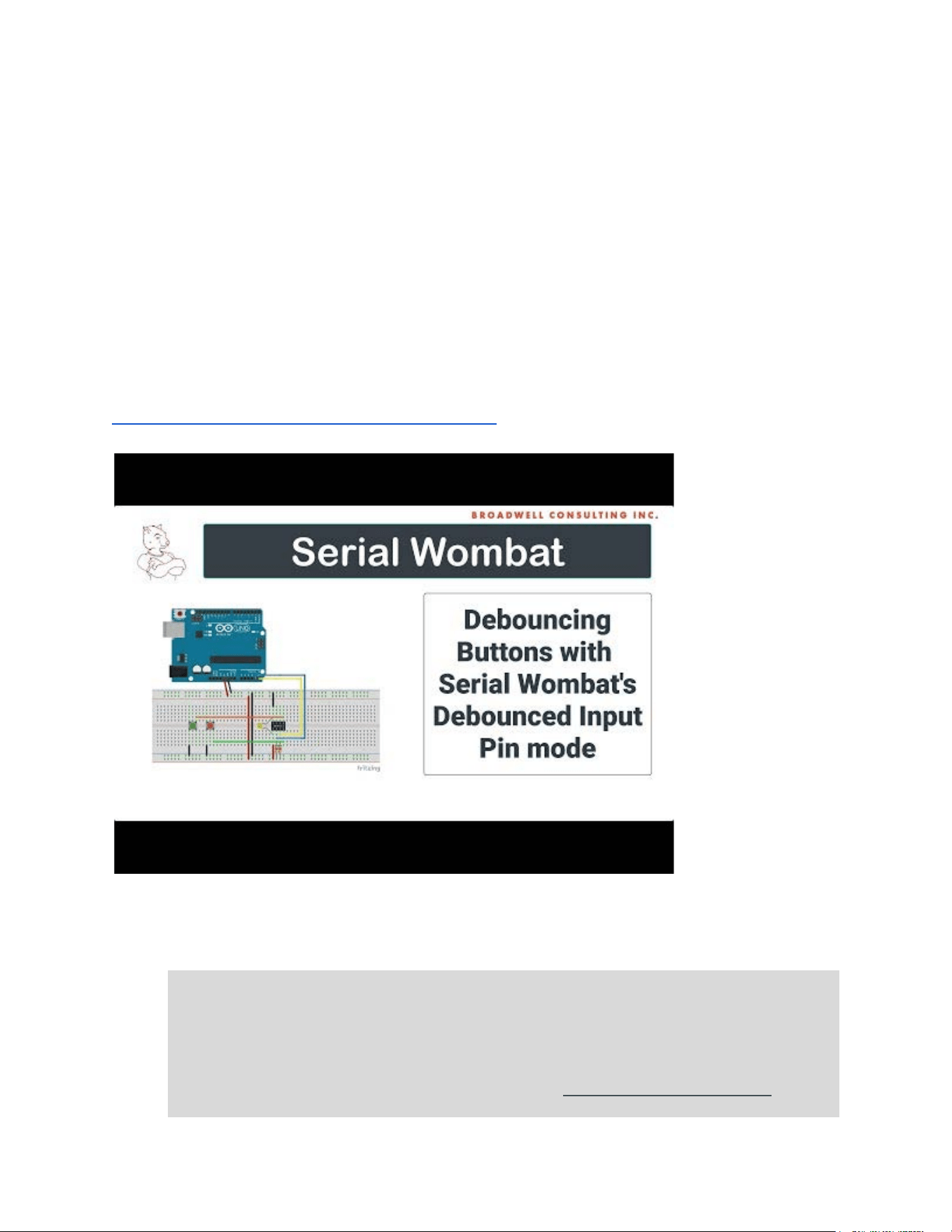
The Debounced Input pin mode allows inversion of the signal so that inputs can report “true”
when the input is low, such as when the pin is connected to ground through a button. This can
make interfaces that produce a low input when active more intuitive to process.
The Debounced Input pin mode can enable an internal pull up resistor in the Serial Wombat chip
which allows a typical button or switch to be used with no additional components when
connected to ground.
A wrapper class is available on Arduino which can increment or decrement a variable at
increasing speeds based on how long a button is held down.
A video tutorial on this pin mode is available here for the Serial Wombat 4B chip (the Serial
Wombat 18AB chip implements equivalent functionality):
https://www.youtube.com/watch?v=R1KM0J2Ug-M
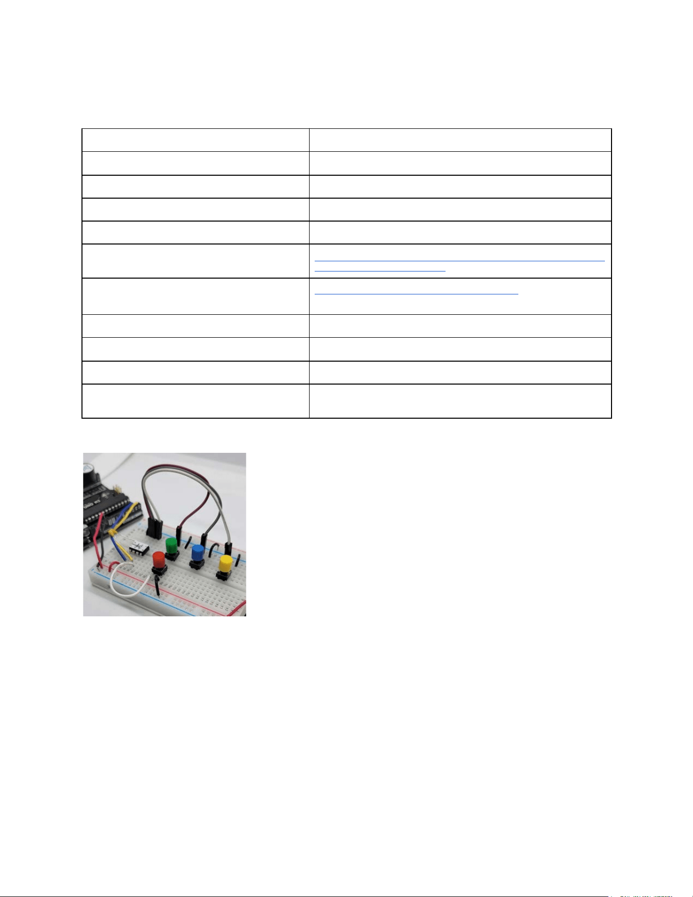
Here’s an Arduino example of the Debounced Input pin mode from the Arduino library
examples:
#include < SerialWombat . h >
SerialWombatChip sw; //Declare a Serial Wombat
SerialWombatDebouncedInput redButton(sw);
SerialWombatDebouncedInput greenButton(sw);
// This example is explained in a video tutorial at: https://youtu.be/R1KM0J2Ug-M
Serial Wombat 18AB Chip User Guide Page 42 of 119
V2.1.0_A

void setup () {
// put your setup code here, to run once:
{ //I2C Initialization
Wire . begin ();
sw . begin ( Wire , 0x6B); //Initialize the Serial Wombat library to use the primary I2C
port, SerialWombat is address 6B.
}
redButton . begin (0);
greenButton . begin (1);
Serial . begin (115200);
}
void clearTerminal()
{
Serial . write (27); // ESC command
Serial . print ( "[2J" ); // clear screen command
Serial . write (27);
Serial . print (
"[H" ); // cursor to home command
}
int greenTransitions = 0;
int redTransitions = 0;
void loop () {
clearTerminal();
redButton . readTransitionsState ();
redTransitions += redButton . transitions ;
greenButton . readTransitionsState ();
greenTransitions += greenButton . transitions ;
Serial . print (greenTransitions);
Serial . print ( " " );
Serial . println (greenButton . readDurationInTrueState_mS());
Serial . print (redTransitions);
Serial .
print ( " " );
Serial . println (redButton . readDurationInTrueState_mS());
delay (50);
}
Serial Wombat 18AB Chip User Guide Page 43 of 119
V2.1.0_A
TM1637 Seven Segment Display Pin Mode
Pin Mode Name
TM1637
Pin Mode Firmware ID
11
Pin Type Required
Any
Available on Serial Wombat 4B chips
No
Serial Wombat 18AB Throughput consumed
5% (varies by configuration)
Arduino Class Documentation
https://broadwellconsultinginc.github.io/SerialWombatArdLib/class_serial
_wombat_t_m1637.html
Tutorial Video
https://youtu.be/AwW12n6o_T0
Implements Processed Input Functions
No
Implements Scaled Output Functions
No
Requires Timing Resource Manager resources
No
Functions if Timing Resource Manager resources are
unavailable
N/A
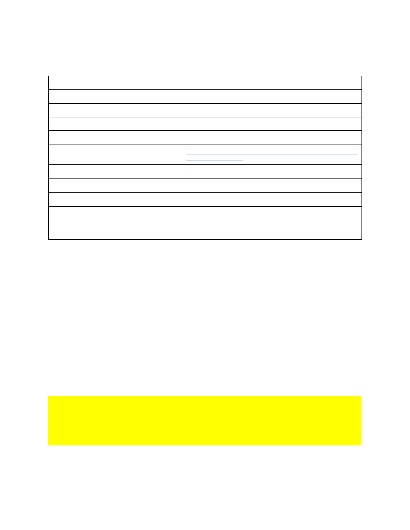
The TM1637 Pin Mode connects a TM1637 Seven-Segment Display to two Serial Wombat
pins.
The pin mode is State Machine driven in firmware for a TM1637 Seven Segment LED Display.
The Serial Wombat TM1637 driver can be configured in a number of ways:
● The Display shows the current value in Hex or decimal of a Pin's public data (including
values written to the pin used to control the display)
● The Display shows an array of characters (as best they can be shown on a seven
segment display) commanded by the host
● The Display shows raw 7-segment bitmaps commanded by the host
● The Display shows an animation downloaded to the Serial Wombat chip by the host.
See the available examples in the Arduino Library for usage.
Note: Different TM1637 displays behave differently based on how the manufacturer routed the
LED matrix pins to the TM1637 outputs on the PCB. This can cause digits to be displayed in
the wrong order, or cause decimal points or clock colons to malfunction. This is a display issue,
not an issue with this library or the Serial Wombat firmware. Display order issues can be
corrected with the orderDigits() command in the Arduino / Python / C# libraries.
A tutorial is available here:
Serial Wombat 18AB Chip User Guide Page 44 of 119
V2.1.0_A
https://youtu.be/AwW12n6o_T0
WS2812 RGB LED Pin Mode
Pin Mode Name
WS2812
Pin Mode Firmware ID
12
Pin Type Required
Enhanced Digital Performance
Available on Serial Wombat 4B chips
No
Serial Wombat 18AB Throughput consumed
5% (varies by configuration)
Arduino Class Documentation
https://broadwellconsultinginc.github.io/SerialWombatArdLib/class_serial
_wombat_w_s2812.html
Tutorial Video
https://youtu.be/WoXvLBJFpXk
Implements Processed Input Functions
No
Implements Scaled Output Functions
No
Requires Timing Resource Manager resources
No
Functions if Timing Resource Manager resources are
N/A
Serial Wombat 18AB Chip User Guide Page 45 of 119
V2.1.0_A
Pin Mode Name
WS2812
Pin Mode Firmware ID
12
unavailable
A pin mode for controlling a WS2812 or compatible RGB LED array from a Serial Wombat pin
This class is only supported on the Serial Wombat SW18AB chip.
This class controls a State Machine driven driver for a WS2812 compatible RGB LED string.
The Serial Wombat WS2812 driver can be configured in a number of ways:
● The driver lights up the LEDs one at a time in sequence (intended for initial testing and
led sequence verification)
● The driver shows colors as commanded by the host
● The driver cycles through arrays of colors at a specified rate
● The driver shows a two-color bar graph based on a pin’s 16 bit public data.
See the available examples in the Arduino/Python/C# Libraries for usage.
Note! Different WS2812 pcbs behave differently based on how the manufacturer routed the
LEDs on the PCB Board. For instance a square 4x4 matrix may not light in the order expected.
This is not an issue with the Serial Wombat pin mode.
Warning: An array of WS2812 LEDs can pull lots of current. Lighting multiple LEDs at full
brightness may consume more power than your supply can provide, causing the system voltage
to become unstable. An unstable system voltage can cause unreliable operation of the Serial
Wombat chip.
The Serial Wombat WS2812 driver is extremely efficient in terms of processor time since it uses
the PIC24FJ256GA702's DMA and SPI hardware to generate the WS2812 signal. This allows
the Serial Wombat firmware to easily clock out WS2812 signals while doing other things.
However, this method is very RAM intensive, requiring about 50 bytes of ram for each LED.
The RAM used for buffering this signal is stored in the User RAM Buffer , an array available for
the user to allocate to various PIN modes' uses (see User RAM Buffer for more information). In
Version 2.1.0 of the Serial Wombat 18AB firmware there is 8k of RAM allocated to User RAM
Buffer, allowing about 160 LEDs to be used if all RAM is allocated to the WS2812 pin.
A number of frames to be shown in rotation with configurable delays in between can also be
stored in the User Buffer. This is in addition to the rendering buffer. Each animation frame
requires
Serial Wombat 18AB Chip User Guide Page 46 of 119
V2.1.0_A
2+3*NumberOfLEDs bytes.
The Update rate is variable with the number of LEDs so that rendering of colors into the User
Buffer is spread across multiple Serial Wombat 1mS execution frames. The LEDs will be
updated approximately every X mS, where X is the number of LEDs plus 20.
This pin mode requires access to the Serial Wombat 18AB’s DMA Channel 5 and SPI internal
peripherals. LED clock-out will be delayed if these resources are not available.
A tutorial is available here:
https://youtu.be/WoXvLBJFpXk
The following is an example of a Serial Wombat 18AB chip creating a “Stop Light” style
animation on a 3 LED WS2812 LED strip. The Serial Wombat chip updates the LEDs
automatically in a pattern without additional instructions from the host.
#include "SerialWombat.h"
/*
This example shows how to initialize an animation on a strip/board of WS2812b or equivalent LEDs.
This sketch uses
the SerialWombat18AB's SerialWombatWS2812 class to configure a pin to drive the LEDs. The
selected pin must be an enhanced performance pin.
When executed this sketch will download 3 frames of 3 leds each to the Serial Wombat chip's user
buffer area. It will cycle the frames
out to the WS2812 LED array and delay between each frame based on a specified per-frame delay.
In this example a Green/Yellow/Red
Serial Wombat 18AB Chip User Guide Page 47 of 119
V2.1.0_A

traffic light will be simulated, with red and green on for 5 seconds each, and yellow on for 1
second.
Change the WS2812_PIN below to fit your circuit.
A video demonstrating the use of the WS2812b pin mode on the Serial Wombat 18AB chip is available
at:
//TODO
Documentation for the SerialWombatTM1637 Arduino class is available at:
https://broadwellconsultinginc.github.io/SerialWombatArdLib/class_serial_wombat_w_s2812.html#deta
ils
*/
SerialWombat sw;
SerialWombatWS2812 ws2812(sw);
#define WS2812_PIN 15 // Must be an enhanced performance pin: 0,1,2,3,4,7,9,10-19
#define NUMBER_OF_LEDS 3
#define WS2812_USER_BUFFER_INDEX 0x0000 // Set this to an index into the on-chip user buffer.
Can't overlap with area used by other pins.
// Define colors. prefix them with SW_ so we don't conflict with any other libraries, such as a
graphic display library.
#define SW_RED 0x000F0000 // Red, changed from 0x00FF0000 to reduce power
#define SW_GREEN 0x0000F00
#define SW_WHITE 0x000F0F0F
#define SW_YELLOW 0x000F0F00
#define SW_BLUE 0x0000000F
#define SW_OFF 0x00000000
#define SW_PURPLE 0x000F000F
#define NUMBER_OF_FRAMES 3
uint32_t Frames[NUMBER_OF_LEDS][NUMBER_OF_FRAMES] =
{
{SW_OFF , SW_OFF , SW_GREEN} ,
{SW_OFF , SW_YELLOW
, SW_OFF} ,
{SW_RED , SW_OFF , SW_OFF} ,
};
void setup () {
// put your setup code here, to run once:
Wire . begin ();
Serial . begin (115200);
delay (500);
uint8_t i2cAddress = sw . find ();
if (i2cAddress == 0) { showNotFoundError(); while (1){ delay (100);}}
sw . begin ( Wire , i2cAddress);
ws2812 . begin (WS2812_PIN , // The Pin connected to WS2812 array
NUMBER_OF_LEDS , // The number of LEDs being used
WS2812_USER_BUFFER_INDEX);
// A location in the Serial Wombat chip's user RAM area where LED
output signals will be buffered
int16_t offset = ws2812 . readBufferSize (); // We have a second location in the Serial Wombat
chip's user buffer. This is where
Serial Wombat 18AB Chip User Guide Page 48 of 119
V2.1.0_A

// The animation frames are stored. The
readBufferSize() method gets the length of
// buffer used by the configured number of LEDs.
ws2812 . writeAnimationUserBufferIndex (WS2812_USER_BUFFER_INDEX + offset , // Location in
memory to store the animation frames, after the main WS2812 buffer
NUMBER_OF_FRAMES // Number of frames
);
for ( int i = 0; i < NUMBER_OF_FRAMES; ++ i)
{
ws2812 . writeAnimationFrame (i , Frames[i]); // Transfer the frame to the animation buffer
on the Serial Wombat chip
ws2812 . writeAnimationFrameDelay (i , 5000); // Initalize All Frames 5000 mS delay
}
ws2812 . writeAnimationFrameDelay (1 , 1000); //Make the yellow frame (index 1 ) only 1000 mS
instead of 5000.
ws2812 . writeMode (
ws2812ModeAnimation );
}
void loop () {
// No code in here. The Serial Wombat chip handles generating the LED sequence with no
additional
// help from the Arduino. In fact, you could unplug the I2C lines and it would continue
working until
// powered down.
}
Serial Wombat 18AB Chip User Guide Page 49 of 119
V2.1.0_A
Hardware UART Receive and Transmit Pin Mode
Pin Mode Name
Hardware UART
Pin Mode Firmware ID
17 and 23
Pin Type Required
Enhanced Digital Performance
Available on Serial Wombat 4B chips
Yes
Serial Wombat 18AB Throughput consumed
Negligible
Arduino Class Documentation
https://broadwellconsultinginc.github.io/SerialWombatArdLib/class_serial
_wombat_u_a_r_t.html
Tutorial Video
https://youtu.be/C1FjcaiBYZs (Serial Wombat 4B chip Equivalent Pin
Mode)
Implements Processed Input Functions
No
Implements Scaled Output Functions
No
Requires Timing Resource Manager resources
No
Functions if Timing Resource Manager resources are
unavailable
N/A
This pin mode allows use of the Serial Wombat 18AB chips's internal two UART hardware
modules to send and receive data at standard baud rates in 8-N-1 format.
The Serial Wombat 18AB chip has a 64 byte transmit buffer and 128 byte receive buffer.
Therefore, up to 64 bytes can be sent to the SerialWombatUART at a time.
Attempts to send more than that will result in the write, print, etc command
blocking until space is available on the SerialWombatUART to buffer the data.
Received data is buffered on the Serial Wombat chip until it is retrieved from the
host.
Note: Due to the overhead of querying and retrieving data from the SerialWombatUART,
data loss is likely when receiving streams of data greater than the buffer size at higher
baud rates.
To minimize this possibility, read data frequently from the Serial Wombat chip.
This pin mode can Send, Receive, or both. Two instances of this pin mode can be used on the
Serial Wombat 18AB chip by using the interface begin() call which takes a hardware indicator of
0 or 1.
On Arduino the wrapper class for this pin mode inherits from the Arduino Stream class, so
functions such as println() can be used once the UART is initialized.
Serial Wombat 18AB Chip User Guide Page 50 of 119
V2.1.0_A
A full Serial Wombat packet send / receive sequence (8 bytes in each direction) over I2C is
necessary to query the status of the queues or to read or receive a byte of data. Therefore, the
protocol becomes more efficient if multiple bytes are read or written using the readBytes or
write(const uint8_t* buffer, size_t size) interfaces rather than read() or write(uint8_t data).
The class must be assigned to a pin. This may be either the receive or transmit pin.
Serial Wombat 18AB pins must be enhanced digital performance pins.
Available baud rates are:
- 300
- 1200
- 2400
- 4800
- 9600
- 19200
- 38400
- 57600
- 115200
https://youtu.be/C1FjcaiBYZs
Serial Wombat 18AB Chip User Guide Page 51 of 119
V2.1.0_A
Software UART Receive and Transmit Mode
Pin Mode Name
Software UART
Pin Mode Firmware ID
13
Pin Type Required
Any
Available on Serial Wombat 4B chips
no
Serial Wombat 18AB Throughput consumed
High - Varies with baud rate and send/receive frequency
Arduino Class Documentation
https://broadwellconsultinginc.github.io/SerialWombatArdLib/class_serial
_wombat_u_a_r_t.html
Tutorial Video
N/A
Implements Processed Input Functions
No
Implements Scaled Output Functions
No
Requires Timing Resource Manager resources
No
Functions if Timing Resource Manager resources are
unavailable
N/A
This pin mode allows pins to send or receive UART data via signal processing implemented in
the Serial Wombat 18AB’s firmware. This mode can be used when insufficient hardware based
UARTs are available to meet user needs.
A queue in the User Buffer area is allocated for RX and one for TX prior to as part of begin for
this mode. Size of these queues should be determined based on system needs. The User
needs to ensure that the created queues do not overlap with other structures created in the
User Buffer. See the section on User RAM Buffer Queues for more information
Warning: The Serial Wombat Software UART pin mode requires significant CPU utilization on
the Serial Wombat microcontroller. This utilization increases as baud rates and bytes processed
increase. The Serial Wombat chip is not capable of running the Software UART pin mode on
all pins simultaneously due to processing power constraints. Exceeding more than the available
CPU power may cause the Serial Wombat chip to malfunction. See the section on Serial
Wombat 18AB Throughput management for more information.
Note: Due to the overhead of querying and retrieving data from the SerialWombat Software
UART, data loss is likely when receiving streams of data greater than the buffer size at higher
baud rates.
On Arduino the wrapper class for this pin mode inherits from the Arduino Stream class, so
functions such as println() can be used once the UART is initialized.
Serial Wombat 18AB Chip User Guide Page 52 of 119
V2.1.0_A

A full Serial Wombat packet send / receive sequence (8 bytes in each direction) over I2C or the
main UART is necessary to query the status of the queues or to read or receive a byte of data.
The protocol becomes more efficient if multiple bytes are read or written using the readBytes or
write(const uint8_t* buffer, size_t size) interfaces rather than read() or write(uint8_t data).
The class must be assigned to a pin. This may be either the receive or transmit pin.
Available baud rates are:
- 300
- 1200
- 2400
- 4800
- 9600
- 19200
- 38400 (Transmit only, receive may be unreliable )
- 57600 (Transmit only, receive may be unreliable )
Serial Wombat 18AB Chip User Guide Page 53 of 119
V2.1.0_A
Processed Input Testing Pin Mode
Pin Mode Name
Processed Input Testing
Pin Mode Firmware ID
14
Pin Type Required
Any
Available on Serial Wombat 4B chips
no
Serial Wombat 18AB Throughput consumed
negligible
Arduino Class Documentation
https://broadwellconsultinginc.github.io/SerialWombatArdLib/class_serial
_wombat_processed_input_pin.html
Tutorial Video
N/A
Implements Processed Input Functions
No
Implements Scaled Output Functions
No
Requires Timing Resource Manager resources
No
Functions if Timing Resource Manager resources are
unavailable
N/A
The Serial Wombat 18AB Processed Input Testing pin mode implements the Processed Input
Pin Mode set of standardized signal measurement features for filtering, averaging, queuing,
scaling, min/max tracking and outlier exclusion. It does not output any signal on the pin. It is
primarily designed to facilitate unit testing of the Processed Input functions. See the Processed
Input Pin Modes section for more information.
Serial Wombat 18AB Chip User Guide Page 54 of 119
V2.1.0_A
Matrix Keypad Pin mode
Pin Mode Name
Matrix Keypad
Pin Mode Firmware ID
15
Pin Type Required
Any
Available on Serial Wombat 4B chips
no
Serial Wombat 18AB Throughput consumed
TBD
Arduino Class Documentation
https://broadwellconsultinginc.github.io/SerialWombatArdLib/class_serial
_wombat_matrix_keypad.html
And
https://broadwellconsultinginc.github.io/SerialWombatArdLib/class_serial
_wombat_matrix_button.html
Tutorial Video
https://youtu.be/hxLda6lBWNg
Implements Processed Input Functions
No
Implements Scaled Output Functions
No
Requires Timing Resource Manager resources
No
Functions if Timing Resource Manager resources are
unavailable
N/A
The Serial Wombat SW18AB Matrix Keypad mode implements a state machine that uses
multiple pins to scan matrix keypads up to 4x4
This class allows the user to declare up to 4 row and 4 column pins which are strobed
continuously to read up to 16 buttons. The Serial Wombat chip's internal pull-up resistors are
used so no additional hardware is necessary. Standard matrix keypads can be attached directly
to the Serial Wombat chip pins.
All Serial Wombat 18AB chip pins can be used in any combination or order.
Results can be returned to the host as a binary 16 bit number indicating the state of 16 buttons,
as an index indicating which button is currently pressed (0 for Col 0 Row 0, 3 for Col 3 Row 3
and 12 for Col 0 Row 3), or as ASCII values which assume a standard keypad layout.
Index mode:
|0 1 2 3 |
|4 5 6 7 |
|8 9 10 11|
|12 13 14 15|
With 16 being used for no current press, depending on mode setting
Serial Wombat 18AB Chip User Guide Page 55 of 119
V2.1.0_A

Ascii Mode:
|1 2 3 A|
|4 5 6 B|
|7 8 9 C|
|* 0 # D|
Note that the key indexes remain the same regardless of how many rows and columns are
enabled.
The wrapper class under Arduino inherits from the Arduino Stream class, so queued keypad
presses can be read like a Serial port.
The Serial Wombat 18AB firmware also keeps track of button transition counts and time since
last transition for all 16 buttons. In this way each key of the keypad can be treated equivalently
to a SerialWombatDebouncedInput class when encapsulated in a SerialWombatMatrixInput
class. See the documentation on this class and Arduino examples for details.
The 16 Bit public data presented internally to other Serial Wombat pins and through the
SerialWombatChip.readPublicData method can be configured to present the binary state of 16
buttons, the last button index pressed, the last button index pressed or 16 if no button is
pressed, or ASCII of last button pressed. The Pulse On Change pin mode can be combined
with the Matrix Keypad class to beep or blink an LED when a key is pressed.
A Tutorial video is available:
Serial Wombat 18AB Chip User Guide Page 56 of 119
V2.1.0_A
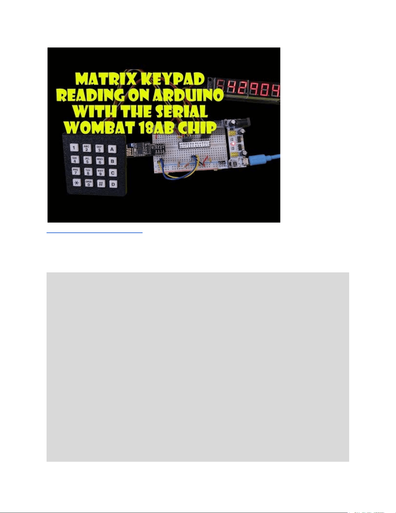
https://youtu.be/hxLda6lBWNg
The following is an example of a 16 key matrix keypad begin read in ASCII mode under
Arduino:
#include < SerialWombat . h >
/*
This example shows how to initialize a 16 key, 8 pin 4x4 matrix keypad using the
Serial Wombat 18AB chip'sSerialWombatMatrixKeypad class.
This example shows how to treat the matrix keypad as a stream input
so that it can be treated as if keypresses are Serial Input
Note that firmware versions prior to 2.0.7 have a bug that may cause slow recognition of
button presses.
This example assumes a 4x4 keypad attached with rows connected to pins 10,11,12,13
and columns attached to pins 16,17,18,19 . This can be changed in the keypad.begin
statement to fit your circuit.
This example uses default modes for the SerialWombatMatrixKeypad. The default values
send ASCII to the queue assuming a standard
123A
456B
789C
*0#D
keypad format. See the pin mode documentation (link below) for more information on the
possible buffer and queue modes It is assumed that the Serial Wombat chip is at I2C
address 0x6B.
Serial Wombat 18AB Chip User Guide Page 57 of 119
V2.1.0_A

A video demonstrating the use of the SerialWombatMatrixKeypad class on the Serial Wombat 18AB
chip is available at:
https://youtu.be/hxLda6lBWNg
*/
SerialWombatChip sw;
SerialWombatMatrixKeypad keypad(SW6B);
void setup () {
Serial . begin (115200);
Wire . begin ();
delay (100);
sw . begin ( Wire , 0x6B);
keypad . begin (10 , // Command pin, typically the same as the row0 pin
10 , //row 0
11 , // row 1
12 , // row 2
13 , // row 3
16 , // column 0
17 , // column 1
18 , // column 2
19);
// column 3
}
void loop () {
int i = keypad . read (); // returns a byte, or -1 if no value is avaialble
if (i > 0)
{
Serial . write (( char )i); // We got a keypress. Dump it to the Serial Terminal
}
}
Serial Wombat 18AB Chip User Guide Page 58 of 119
V2.1.0_A
PWM Pin Mode
Pin Mode Name
PWM
Pin Mode Firmware ID
16
Pin Type Required
Any (Enhanced Resolution on Enhanced Digital Capability pins)
Available on Serial Wombat 4B chips
yes
Serial Wombat 18AB Throughput consumed
TBD
Arduino Class Documentation
https://broadwellconsultinginc.github.io/SerialWombatArdLib/class_serial
_wombat_p_w_m__18_a_b.html
Tutorial Videos
https://youtu.be/u4WihhoZnHA , https://youtu.be/Ab-H2pE9ZZk ,
https://youtu.be/Oqdvk5SoaU
Implements Processed Input Functions
No
Implements Scaled Output Functions
Yes
Requires Timing Resource Manager resources
Yes
Functions if Timing Resource Manager resources are
unavailable
Degrades to 17uS resolution
The Serial Wombat PWM pin mode outputs a configurable duty cycle, configurable frequency
PWM signal on a Serial Wombat 18AB pin. Unlike the Serial Wombat 4B chip, all PWM outputs
can run at different frequencies.
Serial Wombat 18AB PWM outputs are driven either by hardware peripherals allocated by the
Timing Resource Manager or by a DMA based software PWM scheme. Up to 6 hardware PWM
outputs are available from the Timing Resource Manager on Enhanced Digital Performance
pins. Simultaneously using other pin modes that use Timing Resource Manager resources may
reduce the number of available hardware driven PWMs. Hardware capable pins can generate
high resolution signals up to about 100kHz, at resolutions up to 16 bits depending on frequency.
DMA based output is limited to transitions every 17uS, so a 1kHz output will have about 6 bits of
resolution and a 100 Hz output will have about 9 bit resolution.
The Serial Wombat 18AB PWM pin mode implements the Scaled Output Pin Mode extension
set of standardized output processing functions. This is useful when adjusting the PWM’s duty
cycle based on another pin’s Public Data value. The Scaled Output Pin Mode extension can
scale the input value, invert the input, limit the rate of change of the output, filter the output,
control the output via hysteresis, control the output via PID control, and scale the final output.
See the Scaled Output Pin Mode section for more information.
Serial Wombat 18AB Chip User Guide Page 59 of 119
V2.1.0_A
Pulse Timer Pin Mode
Pin Mode Name
Pulse Timer
Pin Mode Firmware ID
18
Pin Type Required
Any (future firmware versions will perform better on enhanced digital
performance pins)
Available on Serial Wombat 4B chips
Yes
Serial Wombat 18AB Throughput consumed
TBD
Arduino Class Documentation
https://broadwellconsultinginc.github.io/SerialWombatArdLib/class_serial
_wombat_pulse_timer__18_a_b.html
Tutorial Video
https://www.youtube.com/watch?v=YtQWUub9gYw (Serial Wombat 4B
chip Equivalent Pin Mode)
Implements Processed Input Functions
Yes
Implements Scaled Output Functions
No
Requires Timing Resource Manager resources
No (future improvements will use TRM resources to increase resolution)
Functions if Timing Resource Manager resources are
unavailable
N/A (future versions will degrade to 17uS resolution)
The Serial Wombat Pulse Timer pin mode is useful for timing pulses such as RC Servo pulses,
or reading PWM frequency and duty cycle.
The pin state machine implements the Processed Input Pin Mode set of standardized signal
measurement features for filtering, averaging, queuing, scaling, min/max tracking and outlier
exclusion. See the Processed Input Pin Mode section for more information.
The Serial Wombat chip can measure pulses in either millisecond or microsecond units. The
user should select the correct units based upon pulse length. Measurements with a maximum
value of less than 65535uS should use microsecond mode. Measurements with a maximum
value longer than 65535 uS should use millisecond mode.
This pin mode has a 17uS precision and 2% accuracy (due to internal FRC variation from part
to part).
A future improvement is intended that will microsecond precision when Timing Resource
Manager resources are used.
The Serial Wombat Protocol and Arduino library supports requesting both high and low times in
a single transaction. This allows the most recent high and low times to be read together, which
is important when calculating a PWM duty cycle. However, either the high time or low time may
Serial Wombat 18AB Chip User Guide Page 60 of 119
V2.1.0_A
be the most recently measured value depending on when the request is made which may cause
variation in duty cycle or frequency calculation for quickly changing PWM values.
The number of measured pulses increments for each high/low combination. By reading this
value twice over a given period of time, the host can calculate an approximate frequency of a
signal. The measured pulses value overflows from 65535 to 0 without notice.
A video tutorial on this pin mode is available here (written for the Serial Wombat 4B, but similar
for Serial Wombat 18AB):
https://www.youtube.com/watch?v=YtQWUub9gYw
Here’s an Arduino example of the Pulse Timer pin mode from the Arduino library examples
which reads the high time of 4 channels of an R/C servo receiver:
#include < SerialWombat . h >
SerialWombatChip sw; //Declare a Serial Wombat chip
SerialWombatPulseTimer steering(sw);
SerialWombatPulseTimer throttle(sw);
SerialWombatPulseTimer button(sw);
SerialWombatPulseTimer thumbSwitch(sw);
// This example is explained in a video tutorial at: https://youtu.be/YtQWUub9gYw
void setup () {
// put your setup code here, to run once:
{ //I2C Initialization
Wire . begin ();
sw . begin ( Wire , 0x6B); //Initialize the Serial Wombat library to use the primary I2C port,
SerialWombat is address 6B.
}
steering . begin (0);
Serial Wombat 18AB Chip User Guide Page 61 of 119
V2.1.0_A

throttle . begin (1);
button . begin (2);
thumbSwitch . begin (19);
Serial . begin (115200);
}
void clearTerminal()
{
Serial . write (27); // ESC command
Serial . print ( "[2J" ); // clear screen command
Serial . write (27);
Serial . print ( "[H" ); // cursor to home command
}
int i;
void loop () {
clearTerminal();
Serial . println (steering . readHighCounts ());
Serial . println (throttle . readHighCounts ());
Serial . println (button . readHighCounts ());
Serial . println (thumbSwitch . readHighCounts ());
delay (50);
}
Serial Wombat 18AB Chip User Guide Page 62 of 119
V2.1.0_A
Frame Timer Pin Mode
Pin Mode Name
Frame Timer
Pin Mode Firmware ID
21
Pin Type Required
Any (one pin per chip can be allocated to this mode)
Available on Serial Wombat 4B chips
No
Serial Wombat 18AB Throughput consumed
Negligible
Arduino Class Documentation
N/A (pin mode is enabled from SerialWombatChip class method
setThroughputPin )
Tutorial Video
N/A
Implements Processed Input Functions
No
Implements Scaled Output Functions
No
Requires Timing Resource Manager resources
No
Functions if Timing Resource Manager resources are
unavailable
N/A
The Frame Timer Pin mode on the Serial Wombat 18AB chip is used to make individual 1mS
frame utilization times visible externally. A pin in Frame Timer Pin Mode will go high while the
Serial Wombat firmware is processing pin state machines and low when it is not. This allows
the user to see how much of each 1mS frame is being utilized by pin mode processing. High
time does not include processing time for any received communication packets. See the
section on Serial Wombat 18AB Throughput management for more information. Only one pin
per chip may be configured to this mode. A chip reset is required to disable this function once
enabled.
Serial Wombat 18AB Chip User Guide Page 63 of 119
V2.1.0_A
Capacitive Touch (CapTouch) Pin Mode
Pin Mode Name
Capacitive Touch or CapTouch
Pin Mode Firmware ID
22
Pin Type Required
Analog
Available on Serial Wombat 4B chips
No
Serial Wombat 18AB Throughput consumed
TBD
Arduino Class Documentation
https://broadwellconsultinginc.github.io/SerialWombatArdLib/class_serial
_wombat18_cap_touch.html
Tutorial Video
https://youtu.be/c4B0_DRVHs0
Implements Processed Input Functions
No
Implements Scaled Output Functions
No
Requires Timing Resource Manager resources
Yes
Functions if Timing Resource Manager resources are
unavailable
No
This pin mode allows a metallic object with a thin insulating layer to be used as a capacitive
touch surface. Items like a coin, PCB board, metal plate, etc can be connected directly to the pin
and covered by a thin insulating layer. A finger touch can be detected by the change in
capacitance caused by its presence.
The mode can output either analog or digital values back to the host and as public data to other
pins. In analog mode the A/D reading at the end of a charge cycle is presented. This value gets
smaller when a finger or item causes the capacitance of the sensor to increase. (Smaller A/D
values when finger present, higher values when absent).
In digital mode the class is configured with a high and low limit which cause a digital change in
hysteresis manner. This is useful when treating the touch sensor like a button. In digital mode
the class implements the same interfaces as the SerialWombatDebouncedInput class so that
physical buttons and cap touch inputs can be treated equivalently. Setting the high and low
limits further apart will decrease the chance of false transitions but will also typically decrease
the responsiveness of the sensor.
Output public data values for touched and not touched are configurable. This allows other pin
modes to react based on touch. For instance, the touch and not touched values might be set to
0x4000 and 0xC000 so that a servo set to monitor that public data would move back and forth
between 25% and 75% of its range depending on whether or not a touch is present.
The final touch value is the result of 8 averaged samples in firmware remove noise.
Serial Wombat 18AB Chip User Guide Page 64 of 119
V2.1.0_A
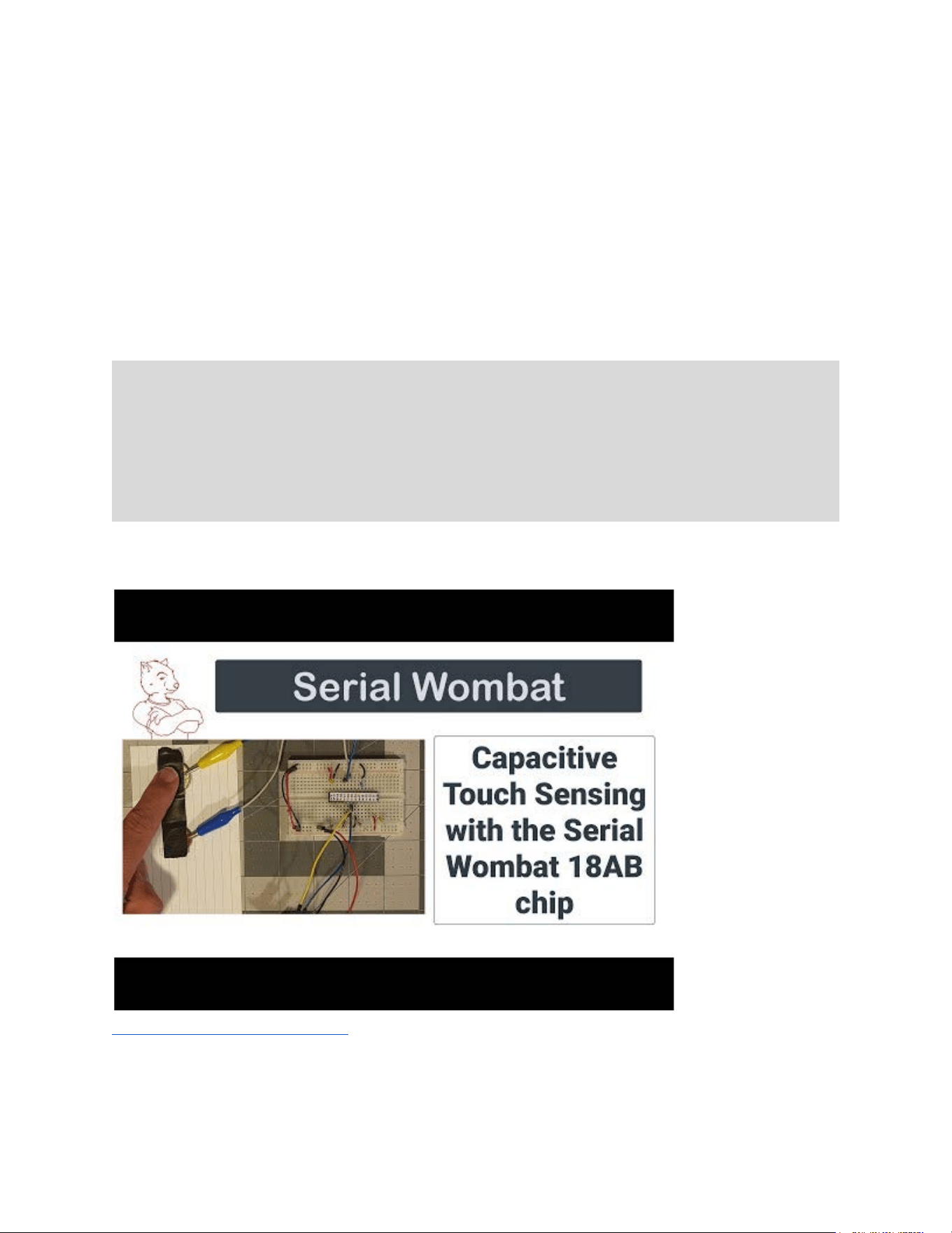
For particularly noisy signals a debounce option is also available. This requires the specified
number of samples to match before a transition is detected. This can help eliminate false
transitions but makes the system less responsive in terms of time to transition after a touch is
made or removed.
For good performance a CapTouch sensor needs to be calibrated. The response of the system
is dependent on the capacitance of the plate, and the dielectric properties of the insulator. An
example sketch is included in Arduino, Python, and C# that will calibrate a sensor. See the
tutorial video for this procedure.
NOTE: The Cap touch pin mode in the firmware takes exclusive access to the Microcontroller's
A/D hardware for a few milliseconds at a time. This isn't an issue for most users if the default
5ms delay between samples is used. However, it should be considered if multiple Cap Touch
pins are being used simultaneously or if the delay is decreased as they may combine to starve
other analog channels and make conversions sporadic, affecting filtering and averaging. This
may also impact performance of real-time control pin modes run on the Serial Wombat chip
such as PID control.
A Tutorial video is available:
https://youtu.be/c4B0_DRVHs0
The following example shows using two pins in CapTouch mode along with a wrapper class that
allows a button, captouch, or matrix button input to increment a variable with increasing speed
Serial Wombat 18AB Chip User Guide Page 65 of 119
V2.1.0_A

the longer it is held. The calibration values in begin and makeDigital calls are based on a prior
calibration using the calibration sketch in the library examples collection.
#include "SerialWombat.h"
/*
This example shows how to configure two Serial Wombat 18AB pins to Touch input and use the
SerialWombat18CapTouchCounter class to implement a two touch sensor interface to increment
a counter at various speeds by two different increments.
The example was created using a Serial Wombat 18AB chip in I2C mode with a Node MCU clone Arduino
and a penny and quarter both covered with electrial tape wired to pins WP16 and WP17.
When the penny is touched briefly the total will increment by 1 cent. When the quarter is
touched
the total will increment by 25 cents. If a finger is held on them then they will increment
slowly, then
more quickly, then very quickly. This type of interface could be easily integrated into a
complete solution
for user configuration of parameters.
SerialWombat18CapTouch class documentation can be found here:
https://broadwellconsultinginc.github.io/SerialWombatArdLib/class_serial_wombat18_cap_touch.html#
details
A demonstration video of this class can be found here:
https://youtu.be/c4B0_DRVHs0
*/
#define I2C_ADDRESS 0x6B
#define PENNY_PIN 16 //Must be an Analog capable pin: 0,1,2,3,4,16,17,18,19
#define QUARTER_PIN 17 //Must be an Analog capable pin: 0,1,2,3,4,16,17,18,19
SerialWombat sw;
SerialWombat18CapTouch penny(sw);
SerialWombat18CapTouch quarter(sw);
SerialWombatButtonCounter quarterCounter(quarter) , pennyCounter(penny);
long int moneyCount = 0; //Place to keep track of total money count in pennies
void setup () {
Wire . begin (); // Initialize I2C
sw . begin ( Wire , I2C_ADDRESS , false ); //Initialize the Serial Wombat Chip
Serial . begin (115200); //Initialize the UART
delay (1000);
VersionCheck(); //Check to ensure the Serial Wombat chip is responding (see other tab)
// Initialize the Penny sensor
//9000 based on previous calibration of this penny on this pin with this wire using the
Calibration example
penny . begin (PENNY_PIN , 9000 , 0);
Serial Wombat 18AB Chip User Guide Page 66 of 119
V2.1.0_A

// Initialize the Penny sensor
//9250 based on previous calibration of this quarter on this pin with this wire using the
Calibration example
quarter . begin (QUARTER_PIN , 9250 , 0);
delay (500);
penny . makeDigital (53985 , 57620 , 1 , 0 , 0 , 0); //Low and High limits based on previous calibration of
this penny on this pin with this wire
quarter . makeDigital (54349 , 57792 , 1 , 0 , 0 , 0); //Low and High limits based on previous calibration of
this quarter on this pin with this wire
delay (250);
pennyCounter . begin ( & moneyCount ,
//moneyCount is the variable we want to increment.
1 , //Increment by 1
500 ,//Every 500 ms
2000 , // for 2000ms, then...
1 , // by 1
250 , // every 250ms
5000 , // for 5000 ms, then
1 , // by 1
100); // every 100ms
//Initialization of the quarter Counter is the same, but incrments by 25.
quarterCounter . begin ( & moneyCount , 25 , 500 , 2000 , 25 , 250 , 5000 , 25 , 100);
Serial . println ( "Touch or hold the penny or the quarter:" );
}
long int
lastCount = - 1; // A copy of moneyCount so we can send a Serial update on changes.
void loop () {
quarterCounter . update (); //Service the counter periodically
pennyCounter . update (); //Serivce the counter periodically
if (lastCount != moneyCount) // Did the counter change the moneyCount variable?
{
//Yes, the counter changed
lastCount = moneyCount; //Make a copy for comparison
//Then build a string and send it.
char moneyCountStr[20];
sprintf (moneyCountStr , "$%ld.%02ld" , moneyCount / 100 , moneyCount % 100);
Serial . println (moneyCountStr);
}
}
Serial Wombat 18AB Chip User Guide Page 67 of 119
V2.1.0_A
Resistance Input Pin Mode
Pin Mode Name
Resistance Input
Pin Mode Firmware ID
24
Pin Type Required
Analog
Available on Serial Wombat 4B chips
No
Serial Wombat 18AB Throughput consumed
TBD
Arduino Class Documentation
https://broadwellconsultinginc.github.io/SerialWombatArdLib/class_serial
_wombat_resistance_input.html
Tutorial Video
https://youtu.be/c4B0_DRVHs0
Implements Processed Input Functions
Yes
Implements Scaled Output Functions
No
Requires Timing Resource Manager resources
No
Functions if Timing Resource Manager resources are
unavailable
N/A
A Pin mode to make resistance measurements with the Serial Wombat 18AB chip.
The SerialWombatResistanceInput
class is used to make resistance measurements on a given pin
up to about 60 kOhm. The measurement must be between the pin and ground.
The pin state machine implements the Processed Input Pin Mode set of standardized signal
measurement features for filtering, averaging, queuing, scaling, min/max tracking and outlier
exclusion. See the Processed Input Pin Mode section for more information. The Serial Wombat
Resistance Input mode makes 20 measurements per second per pin.
Declare and initialize a
SerialWombatResistanceInput instance for each pin being used as a
resistance input.
NOTE: The Resistance Input pin mode in the firmware takes exclusive access to the
Microcontroller's A/D hardware for a few milliseconds at a time. This isn't an issue for most
users if the default 5ms delay between samples is used. However, it should be considered if
multiple Cap Touch pins are being used simultaneously or if the delay is decreased as they may
combine to starve other analog channels and make conversions sporadic, affecting filtering and
averaging. This may also impact performance of real-time control pin modes run on the Serial
Wombat chip such as PID control.
A Tutorial video is available:
Serial Wombat 18AB Chip User Guide Page 68 of 119
V2.1.0_A

Pulse on Change Pin Mode
Pin Mode Name
Pulse on Change
Pin Mode Firmware ID
25
Pin Type Required
Any
Available on Serial Wombat 4B chips
No
Serial Wombat 18AB Throughput consumed
TBD
Arduino Class Documentation
https://broadwellconsultinginc.github.io/SerialWombatArdLib/class_serial
_wombat_pulse_on_change.html
Tutorial Video
N/A
Implements Processed Input Functions
No
Implements Scaled Output Functions
No
Requires Timing Resource Manager resources
No
Functions if Timing Resource Manager resources are
unavailable
N/A
The Pulse on Change Pin Mode monitors other pins’ or public data in the Serial Wombat chip
and generates a pin pulse on change. See the Section on Public Data for more information
about public data.
Pulse on Change is useful to generate a pulse that can drive an interrupt on the host Arduino, or
for creating user alerts such as LED pulses or buzzer tones that acknowledge data reception or
human input.
For instance, a pulse could be generated when the output value of a rotary encoder state
machine on other pins changes value. Or an LED could be pulsed to command traffic on the
Serial Wombat chip by making it pulse when SW_DATA_SOURCE_PACKETS_RECEIVED
changes.
Each Pulse On Change pin can monitor up to 8 other pins or data sources for changes. A pulse
will be generated when any of the criteria (orNotAnd == 1) or all (simultaneously) of the criteria
(orNotAnd == 0) are met. Criteria can be any of the following:
● Pin data or public data changed
● Pin data or public data increased
● Pin data or public data decreased
● Pin data or public data equals a fixed value
● Pin data or public data below a fixed value
● Pin data or public data above a
fixed value
● Pin data or public data not equal to a
fixed value
Serial Wombat 18AB Chip User Guide Page 70 of 119
V2.1.0_A

● Pin data or public data crosses a fixed value
● Pin data or public data crosses (ascending) a
fixed value
● Pin data or public data crosses (descending) a
fixed value
● Pin data or public data equals another pin
● Pin data or public data below another pin
● Pin data or public data above another pin
● Pin data or public data not equal to another pin
● Pin data or public data is within a range
● Pin data or public data is outside a range
The pin mode can be configured with regard to the length and polarity of the pulse produced.
In addition, an active pulse condition can cause a PWM output. This is useful to drive a passive
buzzer or speaker circuit.
Serial Wombat 18AB Chip User Guide Page 71 of 119
V2.1.0_A
High Frequency Servo
Pin Mode Name
High Frequency Servo
Pin Mode Firmware ID
26
Pin Type Required
Enhanced Digital Performance
Available on Serial Wombat 4B chips
No
Serial Wombat 18AB Throughput consumed
TBD
Arduino Class Documentation
https://broadwellconsultinginc.github.io/SerialWombatArdLib/class_serial
_wombat_high_frequency_servo.html
Tutorial Video
https://youtu.be/sCQGRyau40g
Implements Processed Input Functions
No
Implements Scaled Output Functions
Yes
Requires Timing Resource Manager resources
Yes
Functions if Timing Resource Manager resources are
unavailable
No
This pin mode adds support for a frequency/period setting and by changing the on-chip pin
mode to one optimized for high speed servos.
Up to six High Frequency Servo pins may be assigned per Serial Wombat 18AB Chip. This pin
mode claims and holds one of the 6 timing resources also used by PWM output, standard servo
output, etc.
This mode creates rapid pulse outputs by using a PWM rather than pulse generation mode. This
makes it well suited for fast updates, (200 Hz or better) but a poor choice for driving standard
50Hz servos as it will have worse resolution at low speeds than the standard mode.
The Arduino / C# / Python class wrapping this pin mode inherits from the
SerialWombatServo_18AB class, but the interface
void attach(uint8_t pin, bool reverse)
is not available in this mode, as it must be explicitly configured for minimum and maximum pulse
width.
The pulse update rate can be set with writeFrequency() or writePeriod().
This class uses "attach" rather than "begin" to initialize servos to be consistent with the Arduino
Servo native API.
This pin mode implements the Scaled Output Pin Mode extension set of standardized output
processing functions. This is useful when positioning the servo based on another pin’s Public
Serial Wombat 18AB Chip User Guide Page 72 of 119
V2.1.0_A

Data value. The Scaled Output Pin Mode extension can scale the input value, invert the input,
limit the rate of change of the output, filter the output, control the output via hysteresis, control
the output via PID control, and scale the final output. See the Scaled Output Pin Mode section
for more information.
A video tutorial is available:
https://youtu.be/sCQGRyau40g
Serial Wombat 18AB Chip User Guide Page 73 of 119
V2.1.0_A
Ultrasonic Distance Sensor Driver
Pin Mode Name
Ultrasonic Distance Sensor
Pin Mode Firmware ID
27
Pin Type Required
Any (future versions will benefit from Enhanced Digital Performance)
Available on Serial Wombat 4B chips
No
Serial Wombat 18AB Throughput consumed
TBD
Arduino Class Documentation
https://broadwellconsultinginc.github.io/SerialWombatArdLib/class_serial
_wombat_high_frequency_servo.html
Tutorial Video
N/A
Implements Processed Input Functions
Yes
Implements Scaled Output Functions
No
Requires Timing Resource Manager resources
No (future versions Yes )
Functions if Timing Resource Manager resources are
unavailable
N/A (future versions reduced resolution)
The Serial Wombat Ultrasonic Distance Sensor pin mode combines 2 pins to drive an HC-04 or
compatible Ultrasonic distance sensor, and provides the measured distance in millimeters as
the pin mode’s public data based on an assumption that the speed of sound is 343 m/S.
The pin mode can be set up to trigger a sensor reading pulse on command, or to trigger a new
pulse immediately after the prior pulse completes. The number of pulses taken can be retrieved
as a 16 bit number.
The pin state machine implements the Processed Input Pin Mode set of standardized signal
measurement features for filtering, averaging, queuing, scaling, min/max tracking and outlier
exclusion. See the Processed Input Pin Mode section for more information.
Serial Wombat 18AB Chip User Guide Page 74 of 119
V2.1.0_A
Liquid Crystal Character LCD Display Driver
Pin Mode Name
Liquid Crystal
Pin Mode Firmware ID
28
Pin Type Required
Any
Available on Serial Wombat 4B chips
No
Serial Wombat 18AB Throughput consumed
TBD
Arduino Class Documentation
https://broadwellconsultinginc.github.io/SerialWombatArdLib/class_serial
_wombat_liquid_crystal.html
Tutorial Video
N/A
Implements Processed Input Functions
Yes
Implements Scaled Output Functions
No
Requires Timing Resource Manager resources
No
Functions if Timing Resource Manager resources are
unavailable
N/A
This pin mode uses 6 Serial Wombat 18AB pins to connect to HD44780 / 1602 / 4002 / 2004 or
similar interface Character LCDs. This pin mode is only used for connecting in parallel to a
Character LCD. It is not applicable for LCDs that have an I2C interface
This pin mode has nearly identical interfaces to the classic Arduino LiquidCrystal library and can
be used with similar parallel character LCDs. This pin mode is only intended for use with
character LCDs that are connected in 4 bit parallel (E, RS, D4, D5, D6, D7) with the Serial
Wombat chip. RW pin on the LCD must be grounded.
In addition to the classic LiquidCrystal interfaces, this pin mode has a more advanced mode
available through the initializeBufferCopy() interface which allows displays to be updated from
data stored in the Serial Wombat Chip's User Buffer. The Serial Wombat chip will handle getting
the right data to the right location on the display. This is convenient for displays such as 20x4
displays which alternate lines when addressing. When combined with a shifting queue initialized
with SerialWombatQueueType::QUEUE_TYPE_RAM_BYTE_SHIFT, the display can be treated
like any other Stream Class under Arduino. See the Arduino examples directory for an example
of this.
This class also supports buffer copying to large 40x4 character LCDs that have two E lines.
These displays are essentially two 44780 controllers connected to a single piece of glass. See
the example in the Arduino examples directory.
Serial Wombat 18AB Chip User Guide Page 75 of 119
V2.1.0_A

Multiple Liquid Crystal LCD displays may be attached to the Serial Wombat 18AB chip. E (and
optional E2) lines must be exclusive to a single LCD display. If multiple LCDs are attached to a
single Serial Wombat Chip then RS, D4, D5, D6, and D7 can be shared by multiple displays.
When in buffer mode the class updates one character per mS.
Serial Wombat 18AB Chip User Guide Page 76 of 119
V2.1.0_A
High Speed Clock
Pin Mode Name
High Speed Clock
Pin Mode Firmware ID
29
Pin Type Required
Enhanced Digital Performance
Available on Serial Wombat 4B chips
No
Serial Wombat 18AB Throughput consumed
None
Arduino Class Documentation
https://broadwellconsultinginc.github.io/SerialWombatArdLib/class_serial
_wombat_h_s_clock.html
Tutorial Video
N/A
Implements Processed Input Functions
No
Implements Scaled Output Functions
No
Requires Timing Resource Manager resources
No
Functions if Timing Resource Manager resources are
unavailable
N/A
A pin mode which outputs a high speed clock signal suitable for clocking other devices.
This pin mode provides a high speed clock (in the case of the SW18AB Chip up to 32 MHZ).
The number of pins that support this mode and the resolution and frequency options will vary by
base microcontroller.
In the case of the SW18AB chip only one pin may be configured to this pin mode, as the mode
uses the hardware Reference Clock Output, and there is only one reference clock available on
the PIC24FJ256GA702. The selected pin must be an enhanced digital capability pin.
The pin mode takes a 32 bit unsigned integer and outputs that frequency (or the chip's best
approximation of it).
In the case of the SW18AB chip, the output frequency is determined by a hardware clock divider
that either outputs 32MHZ or 32Mhz / 2 * an integer. So 32MHz and 16MHz are possible, but
24MHz (for example) is not. The divisor can range from 1 *2 to 32767 * 2, so the minimum
output frequency is 32000000 / 32767 / 2 = 488 Hz
Note: The SW18AB uses an internal oscillator which has an accuracy of +/- 2 percent. So the
accuracy of the output frequency can vary with the accuracy of the internal oscillator.
If assigning a new pin mode to a pin in HS Clock mode, call the disable method first.
Serial Wombat 18AB Chip User Guide Page 77 of 119
V2.1.0_A
High Speed Counter
Pin Mode Name
High Speed Counter
Pin Mode Firmware ID
30
Pin Type Required
Enhanced Digital Performance
Available on Serial Wombat 4B chips
No
Serial Wombat 18AB Throughput consumed
TBD
Arduino Class Documentation
https://broadwellconsultinginc.github.io/SerialWombatArdLib/class_serial
_wombat_h_s_counter.html
Tutorial Video
N/A
Implements Processed Input Functions
Yes
Implements Scaled Output Functions
No
Requires Timing Resource Manager resources
No
Functions if Timing Resource Manager resources are
unavailable
N/A
This class is used to measure the frequency or cycles of a high speed input. On the Serial
Wombat 18AB chip this class can be used two times, as two clock inputs are available. An
enhanced digital capability pin must be used.
This pin mode has been tested on inputs up to 4MHz on the 18AB.
For frequency measurements a number of counts is divided by a time. The time in mS can be
specified. The frequency is updated every X ms. In order to get a good value, X should be an
even divisor of 1000 (e.g. 1, 2, 4, 25, or 500, but not 3 or 15 or 300).
The counter can be retrieved and optionally be reset on reading.
The public data buffer for this pin mode can be based either on the count of cycles or the
frequency.
Since the public data buffer is limited to 16 bits a divisor is available that's applied to the counter
or frequency before it's copied to the public data buffer. That way a varying high speed
frequency can still create a varying public data buffer rather than saturating at 65535.
When in frequency mode the pin state machine implements the Processed Input Pin Mode set
of standardized signal measurement features for filtering, averaging, queuing, scaling, min/max
tracking and outlier exclusion. See the Processed Input Pin Mode section for more information.
The Processed Input Pin Mode functionality is only updated at the end of each frequency
Serial Wombat 18AB Chip User Guide Page 78 of 119
V2.1.0_A

measurement period, so the time required to average and the effect of filtering will vary
depending on this period.
Serial Wombat 18AB Chip User Guide Page 79 of 119
V2.1.0_A
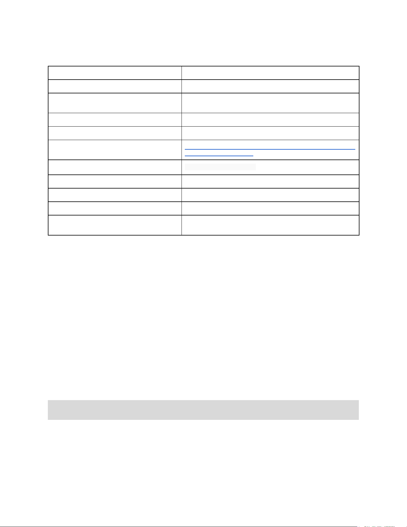
VGA Output Pin Mode
Pin Mode Name
VGA OUTPUT
Pin Mode Firmware ID
31
Pin Type Required
Enhanced Digital Performance, fixed pins 14, 15, 16, 17, and 18 must
be used
Available on Serial Wombat 4B chips
No
Serial Wombat 18AB Throughput consumed
TBD
Arduino Class Documentation
https://broadwellconsultinginc.github.io/SerialWombatArdLib/class_serial
_wombat18_a_b_v_g_a.html
Tutorial Video
https://youtu.be/AymDj_xVlV8 (Preview Video)
Implements Processed Input Functions
No
Implements Scaled Output Functions
No
Requires Timing Resource Manager resources
Yes
Functions if Timing Resource Manager resources are
unavailable
No
This pin mode is designed to drive a VGA monitor RGB and H and V Sync lines. The output is
essentially 1 bit, with the ability to change the color between 8 colors (including black) by
horizontal line.
This pin mode is unusual among SW18AB pin modes because it requires specific pins to be
used for certain things. Pins must be:
VGA VSYNC (VGA Pin 14) -> 100 ohm Resistor -> SW Pin 18
VGA HSYNC (VGA Pin 13) -> 100 ohm Resistor ->SW Pin 17
VGA Red (VGA Pin 1) -> 280 ohm Resistor -> SW Pin 16
VGA Blue (VGA Pin 2) -> 280 ohm Resistor -> SW Pin 15
VGA Green (VGA Pin 3) -> 280 ohm Resistor -> SW Pin 14
Thank you to Nick Gammon who published a very informative article on driving a VGA monitor
here: http://www.gammon.com.au/forum/?id=11608
Note: This pin mode stretches the limits of what the SW18AB chip can do while still being able
to do other things - some flicker / jitter is to be expected
The rate at which the display can be updated is slower than with a hardware connected LCD or
OLED. The Serial Wombat protocol's 8 byte in / 8 byte out packet structure is not ideal for
moving large blocks of data such as screen pixel data. This mode is better suited to data
displays than real-time games, for example.
Serial Wombat 18AB Chip User Guide Page 80 of 119
V2.1.0_A

The pin mode is capable of limited color generation with the restriction that an entire horizontal
line must be the same color. Colors are achieved by turning Red, Green, and Blue lines totally
on or off in combinations.
This pin mode implements a 160x120 pixel output to a monitor in 640x480 mode with black bars
around part of the screen. This was the best I could do using the chip's SPI in DMA mode.
The SerialWombat18ABVGADriver class (A separate Arduino Library) is designed to act as a
wrapper between this pin mode and the AdafruitGFX library. See the Arduino examples for this
pin mode for an example.
This pin mode uses a significant amount of SW18AB time that is not measured using typical
methods due to the high number of interrupts it produces. These interrupts happen both during
and outside of the main loop executive processing, so actual system utilization is higher than
normal metrics indicate.
This pin mode should be considered experimental at this time, and may interact in unexpected
ways with other pin modes. Users using the pin mode should ensure that the system works
properly in their application.
Serial Wombat 18AB Chip User Guide Page 81 of 119
V2.1.0_A
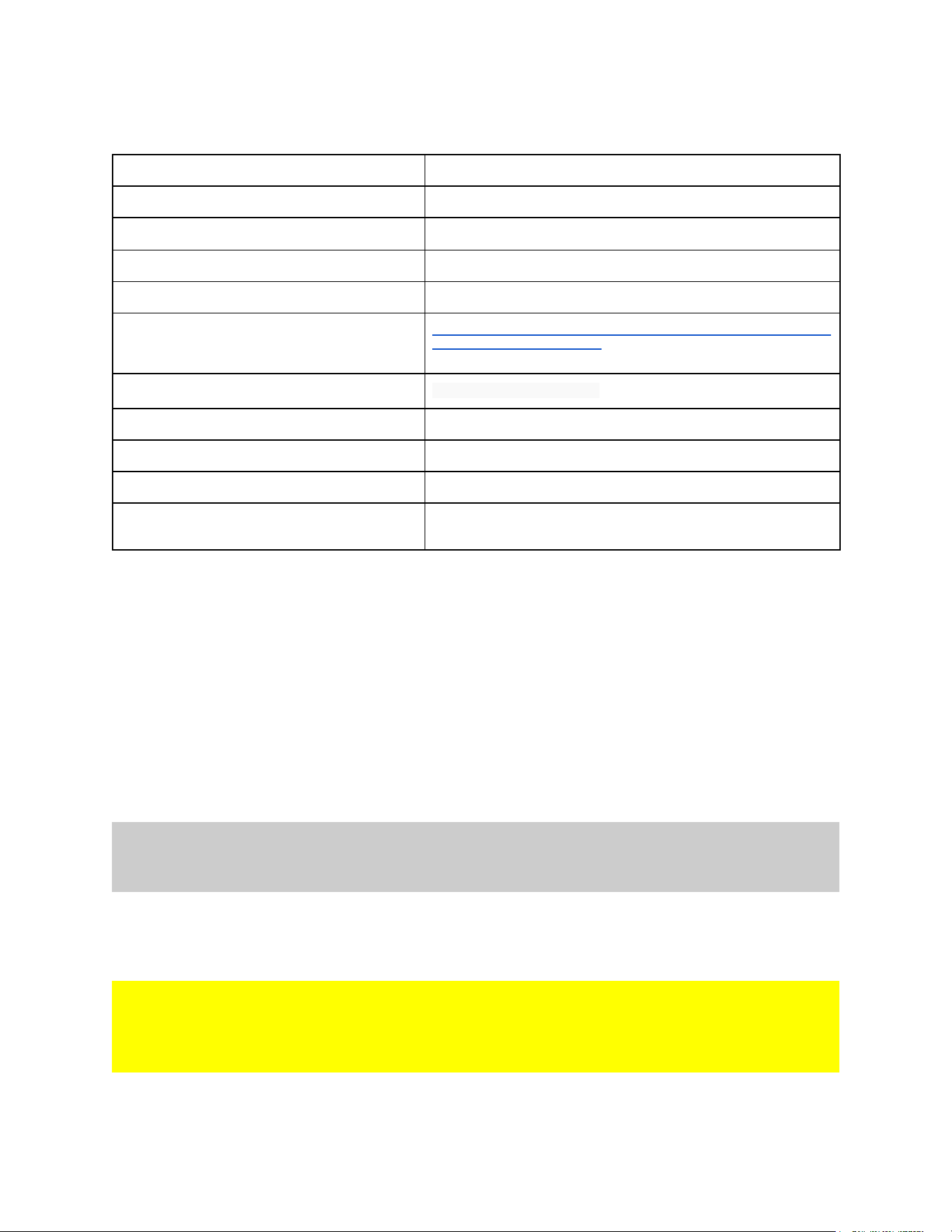
PS2 Keyboard Input Mode
Pin Mode Name
PS2 Keyboard
Pin Mode Firmware ID
32
Pin Type Required
Any, 5V tolerant lines recommended
Available on Serial Wombat 4B chips
No
Serial Wombat 18AB Throughput consumed
TBD
Arduino Class Documentation
https://broadwellconsultinginc.github.io/SerialWombatArdLib/class_serial
_wombat_p_s2_keyboard.html
Tutorial Video
https://youtu.be/YV00GfyxFJU
Implements Processed Input Functions
No
Implements Scaled Output Functions
No
Requires Timing Resource Manager resources
No
Functions if Timing Resource Manager resources are
unavailable
N/A
A pin mode which receives input from IBM PS2 Keyboards.
The class inherits from the Arduino Stream class, so queued ps2 keyboard presses can be read
like a Serial port.
Keys can also be read as PS2 key codes, or as a bitmap of currently pressed keys
This class allows the user to declare a PS2 Keyboard. The PS2 Keyboard class is currently only
supported on the Serial Wombat 18AB chip.
Note: The PS2 Keyboard pin mode requires 20 to 25% of the Serial Wombat 18AB chip's
processor capacity. Assigning pin modes which together exceed available processing capacity
causes malfunctions within the Serial Wombat chip.
The PS2 Keyboard pin mode requires a clock pin (to which this pin mode is assigned) and an
additional data pin. Both should be tied high to 5v with a pull up resistor. I use a 5.1k.
Warning
The PS2 Keyboard inputs are 5V inputs. It is suggested that pins 9,10,11,12,14, or 15 on the
Serial Wombat 18AB chip be used for PS2 Keyboard because they are 5V tolerant. Using other
pins may damage the Serial Wombat chip.
A video Tutorial on this pin mode is available:
Serial Wombat 18AB Chip User Guide Page 82 of 119
V2.1.0_A


Serial Wombat 18AB Pin to Pin interactions
The Serial Wombat 18AB chip is much more capable than other I/O expansion solutions due to
its ability to do real time control. Each pin on the Serial Wombat 18AB chip does not exist in
isolation. The pins are capable of interacting with each other.
For example, it is possible to control a servo from a potentiometer by allocating one pin as an
analog input, and other pin as a servo output, and tying the pins together through the Scaled
Output function of the servo output pin mode. This interaction is configured once by the host
over I2C. Once this happens, the host need not interact any more with the Serial Wombat chip,
and the servo will continue to respond to changes in the potentiometer. The host can query the
Serial Wombat chip when desired to monitor the state of the analog input or servo, or to
reconfigure the pin modes or take direct control of the servo output.
For another example, a rotary encoder can be configured to provide an input value. This value
can be output to a TM1637 display without intervention by the host.
The Processed Input and Scaled Output functions available to some input and output pin modes
provide much more flexibility, allowing values to be scaled, filtered, averaged, and more
between pins. This allows, for example, a digital input such as a button to drive a servo
between two predefined positions without real time assistance from the host.
The Scaled Output functions include PID and Hysteresis feedback control. A PWM pin
configured to do PID control based on a frequency input can provide speed control to a motor
with an encoder without real time interaction from the host. A temperature sensor on an analog
input could control a heater attached to a digital output in hysteresis mode with configured on
and off values to provide a thermostat system.
The pulse on change pin mode is very powerful with respect to monitoring changes in other
pins’ public data. It can provide a pulse or constant digital output when the data of another pin
changes, increases, decreases, etc. It can also be configured to look for any of or a
combination of conditions on other pins. This can be used to provide a digital interrupt or status
signal back to the host, or to blink an LED or sound an acknowledgement tone. It is useful as
an audio feedback to human interface inputs such as buttons, captouch inputs, rotary encoders,
or matrix keypads.
In addition to public data provided by pin modes, the Serial Wombat chip has a number of public
data variables that can be read as if they were pin outputs. Square waves, counts of received
data packets, counts of errors, system source voltage, temperature, and other values are
available. These variables are useful for diagnostic displays such as communication leds,
system voltage, or error beepers. Outputs such as square waves are useful for offloading LED
blinking from the host to the Serial Wombat chip.
Serial Wombat 18AB Chip User Guide Page 84 of 119
V2.1.0_A

Serial Wombat 18AB Public Data Sources
The Serial Wombat 18AB chip provides pin reading and writing and pin-to-pin interaction
through unsigned 16-bit numbers (0 to 65535, or 0 to 0xFFFF in hexadecimal).
The concept of 0 to 65535 representing the full range of available variation is central to the
philosophy and architecture of the Serial Wombat 18AB chip. By expressing all inputs and
outputs in these terms (where possible) the Serial Wombat Chip abstracts inputs and outputs to
all mean the same thing. Some values are represented in absolute units (such as temperature,
resistance, time and voltage), but most others are proportional.
For instance, the position of a servo is represented by a range of 0 to 65535. 0 means the
furthest possible location in one direction, and 65535 means the furthest possible location in the
other. Different servos may require different pulse widths to reach their furthest operation in
each direction, but that is abstracted at the lowest level when the pin mode is initialized. That
way a standard 50Hz signal servo can be controlled in the same way as a high frequency servo
that requires a 333Hz update rate, despite the fact that the pulse width for each is much
different.
The ability to scale inputs and outputs through the Processed input and Scaled Output pin mode
capabilities provides higher abstraction capabilities. For instance, a given servo may move 185
degrees when provided with a pulses that range from 500uS to 2500uS. However, the available
range of motion may be reduced if this servo is installed as a “wrist” in a robot arm, in which
case, the range of motion might be reduced to 110 degrees between 30 and 140 degrees. In
this case, the servo’s Scaled Output scaling function could be used to scale a value of 0-65535
to 30-140 degrees, which would then be converted to appropriate pulse outputs. This would
allow an analog potentiometer (which outputs from 0 to 65535) to control the robot arm’s wrist
directly, using the full range of the potentiometer to control the robot wrist in only its range of
motion.
In another example, a pin configured for pulse measurement mode and connected to an R/C
receiver might read input pulses that range from 750uS to 2250uS. Using the input processing
This concept is why the Serial Wombat 4B and 18AB chips provide A/D conversion results in 0
to 65535 ranges rather than 0-1023 or 0-4095 for 10- and 12-bit conversions. This method has
a number of interesting side effects:
1. A PWM output (with a duty cycle of 0-65535) will produce an analog input reading equal
to the PWM setting if filtered and fed back to an analog input pin.
2. Serial Wombat 18AB a/d conversion and Serial Wombat 4B a/d conversion results are
directly comparable. The SW18AB version is more precise, but scaled the same
(assuming equal Vdd values).
Serial Wombat 18AB Chip User Guide Page 85 of 119
V2.1.0_A

Each pin outputs one 16-bit unsigned value as its public data. This value is updated by the pin
mode’s state machine. In some cases updates are as frequent as every 1mS, and in others
updates come when new measurements are complete.
Some pin modes allow a choice of what measurement becomes that pin’s public data. For
instance, the pulse measurement mode can output the latest high time, low time, period, or
frequency as its public data. Duty cycle would be relevant when reading a PWM signal, period
would be relevant when reading the speed of a motor feedback, and high-time would be
relevant when reading pulses from a servo controller or Radio Control radio receiver.
Other system wide pieces of public data are available in addition to public data provided by
each pin state machine.
Public Data Sources:
SW_DATA_SOURCE_INCREMENTING_NUMBER(65)
An number that increments each time it is accessed.
SW_DATA_SOURCE_1024mvCounts(66)
The number of ADC counts that result from a 1.024V reading
SW_DATA_SOURCE_FRAMES_RUN_LSW(67)
The number of frames run since reset, least significant 16 bits
SW_DATA_SOURCE_FRAMES_RUN_MSW(68)
The number of frames run since reset, most significant 16 bits
SW_DATA_SOURCE_OVERRUN_FRAMES(69)
The number of frames that ran more than 1mS
SW_DATA_SOURCE_TEMPERATURE(70)
The internal core temperature expressed in 100ths deg C
SW_DATA_SOURCE_PACKETS_RECEIVED(71)
The number of incoming command packets that have been processed since reset (rolls over at
65535)
Serial Wombat 18AB Chip User Guide Page 86 of 119
V2.1.0_A

SW_DATA_SOURCE_ERRORS(72)
The number of incoming packets that have caused errors since reset (rolls over at 65535)
SW_DATA_SOURCE_FRAMES_DROPPED(73)
The number of times since reset that a frame ran so far behind that it crossed two subsequent
1ms boundaries, causing a permanent lost frame
SW_DATA_SOURCE_SYSTEM_UTILIZATION(74)
A number between 0 and 65535 that scales to the average length of pin processing frames
between 0 and 1000mS
SW_DATA_SOURCE_VCC_mVOLTS(75)
The system source voltage in mV
SW_DATA_SOURCE_VBG_COUNTS_VS_VREF(76)
A/D conversion of VBG against VRef . Used for mfg calibration
SW_DATA_SOURCE_RESET_REGISTER(77)
Hardware dependent reset reason register contents
SW_DATA_SOURCE_LFSR(78)
A Linear FeedBack Shift register (32,7,5,3,2,1) based pseudo-random number generator
SW_DATA_SOURCE_PIN_0_MV(100)
The public data of Pin 0 expressed as mV. Only applicable to Analog Input mode
mode
SW_DATA_SOURCE_2HZ_SQUARE(164)
Square wave that alternates between 0 and 65535 every 256 frames
SW_DATA_SOURCE_2HZ_SAW(165)
Sawtooth wave that goes from 0 to 65535 to 0 every 512 frames
Serial Wombat 18AB Chip User Guide Page 87 of 119
V2.1.0_A

SW_DATA_SOURCE_1HZ_SQUARE(167)
Square wave that alternates between 0 and 65535 every 512 frames
SW_DATA_SOURCE_1HZ_SAW(168)
Sawtooth wave that goes from 0 to 65535 to 0 every 1024 frames
SW_DATA_SOURCE_2SEC_SQUARE(170)
Square wave that alternates between 0 and 65535 every 1024 frames
SW_DATA_SOURCE_2SEC_SAW(171)
Sawtooth wave that goes from 0 to 65535 to 0 every 2048 frames
SW_DATA_SOURCE_8SEC_SQUARE(173)
Square wave that alternates between 0 and 65535 every 4096 frames
SW_DATA_SOURCE_8SEC_SAW(174)
Sawtooth wave that goes from 0 to 65535 to 0 every 8192 frames
SW_DATA_SOURCE_65SEC_SQUARE(176)
Square wave that alternates between 0 and 65535 every 32768 frames
SW_DATA_SOURCE_65SEC_SAW(177)
Sawtooth wave that goes from 0 to 65535 to 0 every 65536 frames
Serial Wombat 18AB Chip User Guide Page 88 of 119
V2.1.0_A

Processed Input Pin Modes
The Processed Input Pin Mode system allows services to be applied to Serial Wombat inputs
which inherit from it. These include Analog Input, Pulse Timer, Resistance Input, and
UltraSonic Distance Sensor and will include others in the future. The result of the Processed
Input system becomes a pin’s 16 bit public data, available for use by other pins.
This system allows various transformations and filters to be performed on incoming
measurements within the Serial Wombat firmware using the Serial Wombat chip's cpu cycles.
Since this class is processed every 1mS for each pin configured to an input class, it can do
tasks like filtering or averaging much more quickly and consistently than could be achieved by
sampling the value over I2C or UART and doing the computation on the host device. Minimum
and Maximum measured values are also tracked for retrieval by the host
Additionally, this class is capable of limiting input (for example any value below 10000 is
processed as 10000, and any value above 62331 is processed as 62331), scaling input (e.g. an
expected input range of 3000 to 7000 is scaled linearly to the full Serial Wombat Range of 0 to
65535), mx+b linear transformations, exclusion of outlier data (e.g. any value over 50000 is
ignored, and the previous valid measurement is substituted in its place).
Inputs can be inverted (scaled from 0-65535 to 65535-0 by substracting the raw value from
65535). This is useful for reversing the direction of things like analog measured potentiometers.
The final output of the SerialWombatAbstractProcessedInput operations can be queued in a
User Memory Area queue on a periodic basis. This allows synchronous sampling and storage of
input data for retrieval and processing by the host. This allows waveforms to be stored and
processed. Sampling period is an enumerated type ranging from 1mS to 1024mS in power of 2
intervals. When multiple pins use the queue system with the same sampling period, all pins
queue their data in the same frame, allowing further processing of channel differences on the
host.
Data processing happens in the following order each 1mS for any enabled feature:
1. The pin mode measures the physical input
2. Any outlier values are excluded. if a value is excluded the last valid measured raw input
is substituted in its place
3. Inversion of input (subtraction of value from 65535)
4. Transformation of output value (Scale of smaller input range (e.g. 8000-12000 to
0-65535) or mx+b linear transformation
5. Averaging and filtering of the result of prior steps and storage of averaged / filtered
values for access by the host.
6. Selection of the result to be passed to the next steps. The unfiltered value, the averaged
value, or the filtered value can be selected to be the pin's public data output
7. Updating the minimum and maximum recorded value for retreival by the host
Serial Wombat 18AB Chip User Guide Page 89 of 119
V2.1.0_A

8. Sampling the data into a queue in the user buffer
9. Placement of the value into the pin's 16-bit public data buffer for access by the host or
other pin modes that react to a pin's public data buffer.
To use this class first configure the pin to its mode using the normal begin() call for that pin
mode. Then call any configuration commands ( writeInverted, writeTransformLinearMXB, etc)
then call writeProcessedInputEnable(true) to enable processing.
Serial Wombat 18AB Chip User Guide Page 90 of 119
V2.1.0_A
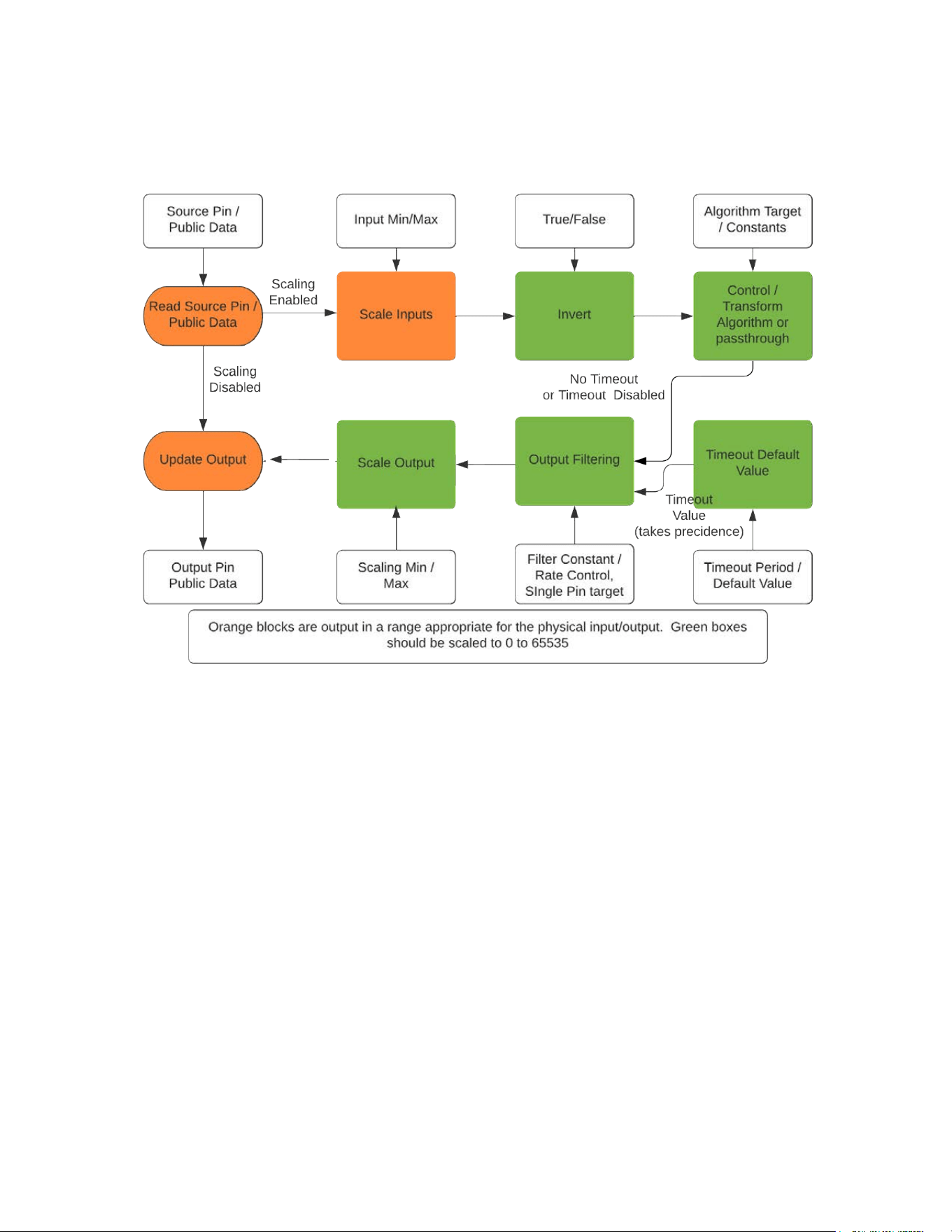
Scaled Output Pin Modes
Servo output, PWM output, and other proportional output classes implement the Scaled Output
set of services. Scaled Output provides control blocks for manipulating output based on input.
Each pin's output block is separate from the others.
Scaled output system is designed to facilitate real time control of outputs based on configuration
from the host without the need to issue additional commands after the initial configuration. The
block also includes a timeout function which is capable of setting an output to predetermined
value if the host does not reset a countdown timer within a specified number of mS. This allows
a controlled shutdown if the host crashes, the data bus becomes inoperable, etc. Because the
output block is serviced every 1mS, real time control can be achieved with higher performance
than if control was performed over the data bus. This functionality also frees the host of the
need to maintain timing sensitive communication with the Serial Wombat chip.
This block can limit output rate of change either by a limited amount of change per time, or by
first-order filtering output changes. Rate limiting is useful to implement smooth motion over time
(controlled within the Serial Wombat chip) such as a model railroad crossing gate attached to a
servo. It also can prevent a current spike caused by requesting large changes in position at one
Serial Wombat 18AB Chip User Guide Page 91 of 119
V2.1.0_A

time. First order filtering is useful to change position rapidly at the beginning, but slow near the
end to reduce impact speed.
The target output value can be provided by the host, or the Scaled Output block can be
configured to get its target value from another pin or a public data source such as the Serial
Wombat 18AB chip's internal temperature sensor or source voltage measurement. This
capability to act on another pin's data would be useful for example if one wanted to control a 6
DOF / 6 servo robotic arm with 6 potentiometer outputs. The Serial Wombat chip could filter
user inputs to provide smooth movement as well as scale the outputs so that the full range of
potentiometer travel can be mapped to each joint's range of servo motion in degrees. The
Arduino or other host could monitor the controls and potentially intervene if higher level logic
deemed it necessary, but would be freed of the need to constantly poll the pots and update
servo pulse values.
The Scaled Output block can also do simple real-time control of an output based on an input.
For instance, a heater could be set to pwm at some duty cycle if an analog input dropped below
a threshold, then shut off when it rose above some other higher threshold. This is hysteresis
mode.
Another control method is Proportional/Integral/Derivative (PID) control. In this mode the host
provides P I and D calibrations for the system, and specifies an input pin and target value. The
output of the Scaled Output block is then controlled via PID to try and reach the target value. As
an example, a motor's encoder output could be attached to a SerialWombatPulseInput pin
configured to output the frequency of incoming pulses. The PID controller in the Scaled Output
block could then vary the PWM driving a FET controlling the motor to keep the motor running at
constant speed that adapts to changing motor load or source voltage. The PID controller
requires that a positive output cause a positive input from the feedback system. If they are
opposite then the invert function of the block can be used.
Scaling operations happen in the following sequence:
1. Read the source pin's or data source's public data (Note that the Host can also provide
the input value by setting the source pin to the output pin and writing that pin's public
data. In this case the output value of the pin will not be written to the pin's public data)
2. Scale the inputs from a specified Min/Max range to 0 to 65535
3. Invert if configured by subtracting the scaled value from 65535
4. Pass the input value to the specified control algorithm (PID, Hysteresis or PassThrough)
to determine the output value
5. Check to see if a communication timeout has occurred if configured. If so, substitute the
default output value
6. Perform output filtering if configured to smooth transitions in the output value
7. Scale the output value from 0-65535 to some other range if configured. This is useful for
example if a servo is physically limited to a portion of its normal rotation.
Serial Wombat 18AB Chip User Guide Page 92 of 119
V2.1.0_A

8. Write the output data to the output pin's public data (unless the pin is configured to use
its own public data as an input source)
9. Write the output data to the underlying pin mode (Servo, PWM, etc) so that the physical
output is updated
Timing Resource Manager
The Serial Wombat 18AB chip is based on the PIC24FJ256GA702 microcontroller. This
microcontroller has a limited number of internal resources which are useful for time related
embedded systems functions such as PWM generation, pulse output, pulse input, and other
similar tasks. There are 3 resources which are good for input or output, 3 which are good only
for output, and 3 which are good only for input.
The Serial Wombat Firmware implements a “Timing Resource Manager”. This is firmware code
that keeps track of which resources are being used, and which are free. When a pin mode
(such as servo or pwm) wishes to use a hardware timing resource, a resource is requested from
the Timing Resource Manager. If an appropriate resource is available, it is allocated to that pin
for use. If no resource is available, the pin mode either fails to operate, or operation is
degraded to using DMA based input / output, which samples at 57,600 Hz (17 uS resolution).
Behavior for each pin mode is documented.
Some pin modes, such as Servo, request a resource, use it briefly, then release it. This is
possible because typical servo output consists of a 500uS to 2500uS pulse which occurs about
every 20mS. The precision of the pulse is important. The delay in between pulses typically is
not. Therefore, the Servo pin mode can request a resource when it needs to generate a pulse,
then release it when the pulse is complete. 8 pins can share the same resource if a 2500uS
pulse is being generated on each.
Other pin modes, such as PWM, High Frequency Servo, and VGA output claim and hold a
resource without releasing it unless told to by the host.
Users should call begin() (or attach() for servos) in an order which corresponds to the timing
accuracy needed by that pin. For instance, a PWM driving a motor or generating an audible
tone may require a high precision in duty cycle and/or frequency, and should be initialized first to
ensure they get access to hardware timing resources. A PWM used to brighten or dim an LED
as part of a user interface would have low precision requirements, and should be initialized later.
SImilarly, servos in an aircraft which control flight surfaces would have high precision
requirements. Servos which control accessories such as landing gear or bomb drop would have
low precision requirements.
Hardware based timing typically requires less CPU time on the Serial Wombat chip than DMA
based timing.
Serial Wombat 18AB Chip User Guide Page 93 of 119
V2.1.0_A

Error Handling
The Serial Wombat 18AB chip includes significant error checking on protocol requests from the
host. Invalid configurations or other requests generate error codes for many scenarios. If the
Serial Wombat chip determines a command is invalid it will return a packet that starts with ASCII
‘E’ followed by an error code. Many but not all of the Arduino/Python/C# interfaces will return
this error code as a negative number. Defined error codes are listed at the end of this section.
The Arduino/Python/C# interfaces allow an error handler to be registered with a
SerialWombatChip instance. This error handler can be used to help debug issues by dumping
error codes to a debug output.
The public data SW_DATA_SOURCE_ERRORS increments each time a communication error is
detected. A Serial Wombat pin can be made to pulse when a communication error occurs. This
is useful when debugging.
The error codes listed below are decoded by the Serial Wombat Protocol Analyzer .
Serial Wombat Error Codes
SW_ERROR_UNNUMBERED_ERROR
(#32767)
SW_ERROR_PINS_MUST_BE_ON_SAME_PORT
(#1) Pins must be on the same microcontroller part (e.g. PORTA, PORTB, etc.). See datasheet
of micro for port assignments.
SW_ERROR_ASCII_NUMBER_TOO_BIG_16
(#2) A number bigger than 65535 was provided to convert to a 16 bit value
SW_ERROR_UNKNOWN_PIN_MODE
(#3) A Pin mode was indicated that is not avaialble on this model or version of Serial Wombat
chip
SW_ERROR_RESET_STRING_INCORRECT
(#4) A Packet starting with 'R' was received but didn't have the correct following bytes to cause
a reset
SW_ERROR_INVALID_COMMAND
(#5) The first byte of a received packet does not correspond with a command supported by this
model of Serial Wombat chip
SW_ERROR_INSUFFICIENT_SPACE
Serial Wombat 18AB Chip User Guide Page 94 of 119
V2.1.0_A

(#6) There was not sufficient space in the queue or user area to complete the command.
SW_ERROR_WUB_COUNT_GT_4
(#7) A count greater than 4 was provided as a number of bytes to write to count user buffer
SW_ERROR_WUB_INVALID_ADDRESS
(#8) An attempt to write to a user buffer address outside the user buffer was attempted.
SW_ERROR_WUB_CONTINUE_OUTOFBOUNDS
(#9) A call to Write User Buffer Continue would have written out of bounds.
SW_ERROR_RF_ODD_ADDRESS
(#10) Addresses Read From Flash must be even.
SW_ERROR_FLASH_WRITE_INVALID_ADDRESS
(#11) An attempt to write or erase flash was made to a protected or non-existant area
SW_ERROR_INVALID_PIN_COMMAND
(#12) The pin command 0xC1, 0xC2, etc is not suported by this pin mode (May vary by model)
SW_ERROR_PIN_CONFIG_WRONG_ORDER
(#13) The called pin command 0xC1, 0xC2 was called before other required prior commands
(e.g. 0xC0)
SW_ERROR_WS2812_INDEX_GT_LEDS
(#14) The command references an index that is greater or equal to the number of leds
SW_ERROR_PIN_NOT_CAPABLE
(#15) The commanded pin does not have the hardware support to perform the commanded pin
mode
SW_ERROR_HW_RESOURCE_IN_USE
(#16) The requested hardware or software resource in use has already been exclusively
claimed by another pin
SW_ERROR_INVALID_PARAMETER_3
(#17) The pin configuration parameter in Byte 3 was invalid
SW_ERROR_INVALID_PARAMETER_4
(#18) The pin configuration parameter in Byte 4 was invalid
SW_ERROR_INVALID_PARAMETER_5
(#19) The pin configuration parameter in Byte 5 was invalid
Serial Wombat 18AB Chip User Guide Page 95 of 119
V2.1.0_A

SW_ERROR_INVALID_PARAMETER_6
(#20) The pin configuration parameter in Byte 6 was invalid
SW_ERROR_INVALID_PARAMETER_7
(#21) The pin configuration parameter in Byte 7 was invalid
SW_ERROR_PIN_NUMBER_TOO_HIGH
(#22) The pin number indicated was greater than the greatest available pin
SW_ERROR_PIN_IS_COMM_INTERFACE
(#23) The pin number indicated is currently being used for Serial Wombat protocol
communications
SW_ERROR_ANALOG_CAL_WRONG_UNLOCK
(#24) The unlock value provided to write analog calibration was incorrect.
SW_ERROR_2ND_INF_WRONG_UNLOCK
(#25) The unlock value provided to enable the 2nd interface was incorrect.
SW_ERROR_2ND_INF_UNAVAILABLE
(#26) The 2nd interface hardware was not available to claim
SW_ERROR_UART_NOT_INITIALIZED
(#27) A UART operation was requested but the UART was not initialized
SW_ERROR_CMD_BYTE_1
(#28) Byte 1 of the command was invalid
SW_ERROR_CMD_BYTE_2
(#29) Byte 2 of the command was invalid
SW_ERROR_CMD_BYTE_3
(#30) Byte 3 of the command was invalid
SW_ERROR_CMD_BYTE_4
(#31) Byte 4 of the command was invalid
SW_ERROR_CMD_BYTE_5
(#32) Byte 5 of the command was invalid
SW_ERROR_CMD_BYTE_6
(#33) Byte 6 of the command was invalid
SW_ERROR_CMD_BYTE_7
Serial Wombat 18AB Chip User Guide Page 96 of 119
V2.1.0_A

(#34) Byte 7 of the command was invalid
SW_ERROR_CMD_UNSUPPORTED_BAUD_RATE
(#35) invalid baud rate enumeration
SW_ERROR_QUEUE_RESULT_INSUFFICIENT_USER_SPACE
(#36)
SW_ERROR_QUEUE_RESULT_UNALIGNED_ADDRESS
(#37)
SW_ERROR_QUEUE_RESULT_INVALID_QUEUE
(#38)
SW_ERROR_QUEUE_RESULT_FULL
(#39)
SW_ERROR_QUEUE_RESULT_EMPTY
(#40)
SW_ERROR_DATA_NOT_AVAILABLE
(#41)
SW_ERROR_TM1637_WRONG_MODE
(#42) The TM1637 pin is configured for the wrong TM1637 mode to process the command
SW_ERROR_RUB_INVALID_ADDRESS
(#43) An attempt to read user buffer address outside the user buffer was attempted.
SW_ERROR_UNKNOWN_OUTPUTSCALE_COMMAND
(#44) The command index for an output scaling command is not supported on this firmware
SW_ERROR_UNKNOWN_INPUT_PROCESS_COMMAND
(#45) The command index for an inputProcess command is not supported on this firmware
SW_ERROR_PULSE_ON_CHANGE_ENTRY_OUT_OF_RANGE
(#46) The pulse on change entry number exceeded the number of entries
SW_ERROR_PULSE_ON_CHANGE_UNKNOWN_MODE
(#47) The pulse on change Mode requested is unknown
SW_ERROR_LESS_THAN_8_BYTES_RETURNED
(#48) The Serial Wombat Chip returned less than 8 bytes (Used at host level, not firmware)
Serial Wombat 18AB Chip User Guide Page 97 of 119
V2.1.0_A

SW_ERROR_REENTRANCY_NOT_SUPPORTED
(#49) The library was used in an unsupported manner, such as calling a communication
command from an interrupt when communication was in progress (Used at host level, not
firmware)
Powerup Self-Configuration
The Serial Wombat 18AB chip is capable of capturing a sequence of commands and playing it
back at powerup prior to any communication. This is useful for putting the Serial Wombat chip
into a state with known outputs immediately after powerup or an unexpected reset. It also
allows the Serial Wombat 18AB chip to be used in a stand-alone fashion for signal conversion
tasks (e.g. analog signal to servo, RC receiver pulse to PWM, UART baud rate conversion, etc).
Up to 256 configuration packets can be stored. The number of packets generated from various
library calls will vary. Assuming 2 packets per library call is a good estimate. Exact numbers for
a given configuration can be measured using the Serial Wombat Protocol Analyzer .
Three library functions are used to store commands. startStartupCommandCapture() begins
the capture process. stopStartupCommandCapture() stops the process, and
writeStartupCommandCapture() initiates a write of the captured commands to flash memory.
The write command may take 10s or 100s of milliseconds to complete.
Packets are stored to the Serial Wombat User Ram area during capture prior to writing. The top
3072 bytes of Serial Wombat User Ram (index 5120 and up) are used for capturing. This area
should not be written to by the host or by pin mode state machines during this time. Doing so
will result in a corrupt startup sequence being written, with unpredictable results at the next
powerup.
It is acceptable for a program to call these three commands every time it runs. When
writeStartupCommandCapture() is called the existing stored commands are examined against
the captured commands. No flash write occurs if they are identical.
Warning: There may be ways that the Powerup Self-Configuration function could cause the
Serial Wombat chip to be unusable if an unacceptable sequence of commands was replayed at
powerup. The user should consider the results of a startup sequence before programming it.
Use of a socket for the Serial Wombat chip when developing applications using Power
Self-Configuration is recommended
The following video shows an example of using Powerup Self-Configuration to allow the Serial
Wombat 18AB chip to use an Ammeter as a room-temperature indicator.
Serial Wombat 18AB Chip User Guide Page 98 of 119
V2.1.0_A

Simultaneous UART and I2C interfacing from 2
Hosts
The Serial Wombat 18AB chip can be controlled via UART or I2C. When controlling the Serial
Wombat chip over I2C it is possible to enable the UART interface on pins 7 and 9 to process
commands over both UART and I2C. A command sent to one interface will be responded to on
that interface. Commands can be sent to both interfaces simultaneously, and the correct
response will be sent to each.
This functionality allows easy monitoring and modification of the Serial Wombat operation from a
PC using the Serial Wombat Panel application over UART while the chip is interacting with an
Arduino or Micropython embedded host over I2C.
In order to enable this functionality the host communicating with the Serial Wombat chip over
I2C calls the enable2ndCommandInterface method of the SerialWombatChip class
Serial Wombat 18AB Chip User Guide Page 99 of 119
V2.1.0_A

Sleep Mode
Sleep mode is not currently implemented in the Serial Wombat 18AB firmware.
Serial Wombat 18AB Chip User Guide Page 100 of 119
V2.1.0_A
Unique Identifier
Each Serial Wombat 18AB chip has a unique, unchangeable identifier programmed into the
microcontroller when it is manufactured by Microchip. A demonstration of this capability is
shown in this video:
https://youtu.be/IHTcKyXT_2Q
Serial Wombat 18AB Chip User Guide Page 101 of 119
V2.1.0_A

Serial Wombat 18AB Temperature Sensor
The Serial Wombat’s base PIC24FJ256GA702 microcontroller includes a low accuracy
temperature sensor based on 3 internal diodes. This sensor can be accessed by reading the
Public Data Source associated with the temperature sensor.
The temperature sensor has good linearity over 0 to 55 degrees C or more. Therefore it is
possible for the user to greatly improve the accuracy by measuring it’s output at two known
temperatures and creating an mX+b correction on the host side.
Serial Wombat Red Label chips are much more accurate around room temperature, as the
internal voltage reference, current source and temperature are compared against high accuracy
references during programming. The Serial Wombat Red Label chips use a single temperature
point calibration as an offset. Users wishing to measure wide temperature ranges may still wish
to do a two point calibration.
See this video for a tutorial:
https://youtu.be/Ab-H2pE9ZZk
Serial Wombat 18AB Chip User Guide Page 102 of 119
V2.1.0_A

Serial Wombat 18AB User RAM Buffer
Each pin in the Serial Wombat 18AB firmware is allocated a static set of bytes to use for its pin
mode state machine. However, some pin modes require more RAM than is allocated by default.
Examples include WS2812, VGA, and software UART pin modes.
The Serial Wombat 18AB firmware V2.1.0 allocates 8192 bytes of RAM to an array called the
User RAM Buffer. This area is used to provide additional RAM to pin modes as needed. The
User is responsible for allocating this RAM in a way that doesn’t result in multiple pins using the
same RAM.
This RAM can also be used as volatile storage for the host.
Serial Wombat 18AB User RAM Buffer Queues
Some pin modes that use the User Ram Buffer store data in queues. In most cases it is up to
the User to initialize those queues before calling the begin() function for a pin mode that uses
that queue. A Serial Wombat Queue is a class defined in the libraries . On Arduino this class
inherits from Stream so it can be used with any code which expects a stream interface.
It is possible for two pins to utilize the same queue. For instance, one could set up a software
UART which received data into the queue at one baud rate, then a second software UART that
transmitted any data in that queue at a different baud rate.
At present two queue types are available. One is a traditional queue with moving head and tail
pointers. It uses 8 bytes of RAM, plus however many bytes are allocated to the queue.
A second type of queue fills its data area with data, then shifts out the oldest data to make room
for new data. In this way, the data remains stored in indexed order based on First In First Out.
This can be useful for making a queue which is easily transferred internally to an LCD or other
similar output.
Serial Wombat 18AB Chip User Guide Page 103 of 119
V2.1.0_A
Serial Wombat 18AB Firmware Structure
This section is background information. Knowledge of the firmware structure may be helpfu, but
is not necessary for use.
The Serial Wombat 18AB firmware runs on the PIC24FJ256GA702 microcontroller. It is
designed for the free version of the XC16 compiler, and the MPLAB X development
environment.
A video that goes over the Serial Wombat Firmware design and how to modify it is available
here:
https://youtu.be/PNPlAaIrR1o
You can compile the firmware yourself and program chips using a PICKIT4 or similar
programming device, or you can buy preprogrammed kits from Broadwell Consulting Inc at
https://www.SerialWombat.com .
The Serial Wombat binary image / Hex File is made up of two separate projects: A bootloader
project and a Serial Wombat firmware project.
Serial Wombat 18AB Chip User Guide Page 104 of 119
V2.1.0_A

Executive Structure
The Serial Wombat firmware is a foreground / background loop system. Important hardware
based events and communications Receive and Transmit to/from queues is done using
interrupts.
The main loop runs a loop with a foreground subroutine that is run every 1 mS based on a flag
which is set in a 1mS hardware timer. In Between runs of the foreground subroutine the
communication receive queue is checked to see if a new command from the host is ready to be
processed. If so, it is processed in its entirety and a response is generated and put into the
transmit queue. It is possible for the start of the foreground subroutine to be delayed by some
microseconds by the communication processing routine.
The main job of the foreground subroutine is to service state machines for the Serial Wombat
pins. Each pin has its own state machine and memory area. Each pin's state machine is
serviced every 1 mS by the executive. Actual time between servicings will vary due to execution
time variation. For instance, one call may be 1100 uS after the previous, then the next call 800
uS after that. But over time it will average out to 1 mS.
The Serial Wombat 18AB firmware relies heavily on 4 DMA channels, one for reading PORTA,
one for writing PORTA, one for Reading PORTB and one for writing PORTB. These DMAs are
triggered by a 57600 Hz timer interrupt, and copy to or from four 128-entry, 16 bit wide circular
buffers. Many 18AB pin modes read or write to these buffers every 1ms. Each 1 ms the pin
mode reads new data read into the buffer since the prior 1ms call, or writes data to the outgoing
circular buffer until it is full. In this way a 1mS call can generate or process wave forms that
happen at 57600 Hz. It is vital that the SW18AB executive process the 1mS state machines on
time to prevent overflow or underflow of the DMA channels.
The Serial Wombat 4A/4B firmwares can run in any combination of pin modes without concern
for processor throughput.
The Serial Wombat 18AB chip can in some cases have pin modes assigned to it in ways that
overload the processor, causing unreliable pin mode operation. This is not a concern for most
users, but can be an issue when many pins are assigned to pin modes that require generation
or inspection of DMA data, for example Software UART modes, or Quadrature encoder mode in
high performance (DMA) mode. Multiple different diagnostics are available for monitoring
processor loading.
Pin State Machines
Each pin has a limited, pre-allocated amount of memory allocated to it. This memory is used to
store the current pin mode choice, 16 bits of public data, and some private data used to
configure or operate the state machine.
Serial Wombat 18AB Chip User Guide Page 105 of 119
V2.1.0_A

A pin is configured to a state machine by CONFIGURE_CHANNEL_MODE command. This
command includes the pin number to be configured, the mode that the pin is being commanded
to, and an index indicating the meaning of bytes in the configuration packet. Many pin modes
can be configured with a single CONFIGURE_CHANNEL_MODE packet. More complicated
modes may require multiple packets, sent in a specific order.
For pin modes that take data from the host (Such as I2C -> UART TX on the SW4B) the
CONFIGURE_CHANNEL_MODE commands are also used to load this data during operation.
For pin modes that generate data for the host (Such as the Pulse Width timer mode) the
CONFIGURE_CHANNEL_MODE commands can be used to retrieve the various different data
made available by that mode.
Each Pin State machine has an init function, a process function, and a structure type which
defines the state machine's data organization. The init function is called whenever a
CONFIGURE_CHANNEL_MODE command is sent by the host. The init function processes the
command, configures the state machine or Serial Wombat hardware as required, and generates
a response as required. Some init responses simply leave the echo default response
unchanged.
Once a pin has been set to a mode, the process function is called every 1mS by the executive.
This is where real-time processing of the pin's state machine happens.
Each pin has a fixed amount of memory allocated to it. There is an array of pin_register_t
unions declared with at least as many elements as there are available state machine pins on the
Serial Wombat chip.
The size of pin_register_t varies by model to allow more powerful chips to allocate more ram to
each state machine. The pin_register_t.generic member is a structure that contains some
number of general-purpose bytes that is consistent for all pin modes on that family of models,
followed by the 16-bit public data for that statemachine, followed by an 8-bit mode byte.
On models with strong indexed addressing capability such as the PIC24FJ256GA702 based
Serial Wombat 18AB chip, iteration through the pins is achieved by a single pointer,
CurrentPinRegister, which is incremented prior to each process call to point to the pin currently
being serviced. The variable CurrentPin is updated to be the pin number currently being
serviced. Similarly, the pointer and index are updated prior to init calls.
On models with weak indexed addressing capability such as the PIC16F15214 based Serial
Wombat 4 series, the array element is copied to a buffer of type pin_register_t prior to pin
process execution. The pin mode then executes against the fixed addresses of the buffered
values. After processing is complete, the buffer is copied back to the array. This has processing
time cost to do the copies, but greatly reduces the code space required for each pin mode,
Serial Wombat 18AB Chip User Guide Page 106 of 119
V2.1.0_A

allowing much more functionality within the limited flash space of the chip. For these chips,
CurrentPinRegister becomes a #define which defines CurrentPinRegister as the address of the
buffer.
When a pin state machine needs to access data which is defined the same way across all state
machines such as the 16-bit public data or pin mode value it accesses it using the pin_register_t
definition:
switch( CurrentPinRegister->generic.mode )
When accessing the pin-mode specific area of the pin_register_t element the
CurrentPinRegister is recast as a pointer to the structure type defined in the pin mode. It is
important that the structure not define variables that take up more space than is allocated for
pin-mode specific data.
Serial Wombat 18AB Throughput Management
The Serial Wombat 18AB chip is firmware running on a 32MHz 16-bit microcontroller. As such,
it has a finite amount of processing power. Some use cases may be limited by the amount of
processing power (throughput) available when running many processor-intensive pin modes.
The Serial Wombat executive runs the state machine for all 20 pins every 1mS. This is called a
1mS Frame. It is essential that each frame complete in 1mS or less. For some pin modes,
such as digital I/O or Analog input, very little processing is required. Some other pin modes
such as PWM depend on whether the PWM signal is being generated in hardware or in
software via DMA. A hardware based PWM takes up very little processing power, but a
software based PWM takes up significantly more. Eventually this guide will have an estimate of
how much processing power each pin mode takes up.
The Serial Wombat chip has internal tracking metrics to allow verification that the current
configuration is not overloading the chip. The public data
SW_DATA_SOURCE_OVERRUN_FRAMES increments any time the processing of a frame
takes more than 1mS and delays the beginning of the next frame. This value should always be
0. If this value is incrementing, then real-time deadlines for pin-mode operation may be missed,
causing malfunctions.
The SW_DATA_SOURCE_SYSTEM_UTILIZATION provides a constantly updating value of
proportion of the frame being used, scaled from 0 to 65535 . This value can be read by the
host, or output as a PWM to be measured by a volt meter or other means.
The Frame Timer Pin Mode can be used to view the Serial Wombat 18AB throughput level
externally. It goes high at the beginning of each frame, and low after all pin state machines
have been serviced in that 1mS frame
Serial Wombat 18AB Chip User Guide Page 107 of 119
V2.1.0_A


Firmware Updates (Bootloader)
The Serial Wombat 18AB chip is programmed with a bootloader program which allows loading
of new firmware versions over I2C or UART. Bootloading of the latest firmware can be done
through an Arduino sketch included in the arduino examples (a relatively high memory part such
as an ESP8266 is required - an Uno doesn’t have enough flash to hold the image).
Bootloading can also be done using the WombatPanel application for windows. Hex images are
available here:
https://github.com/BroadwellConsultingInc/SerialWombat/tree/main/SerialWombat18A_18B/rele
ases
A python/micropython script will be available in the future.
Video Tutorials are available for updating over UART:
https://youtu.be/7UIp910sPS4
And I2C:
https://youtu.be/q7ls-lMaL80
Serial Wombat 18AB Chip User Guide Page 109 of 119
V2.1.0_A
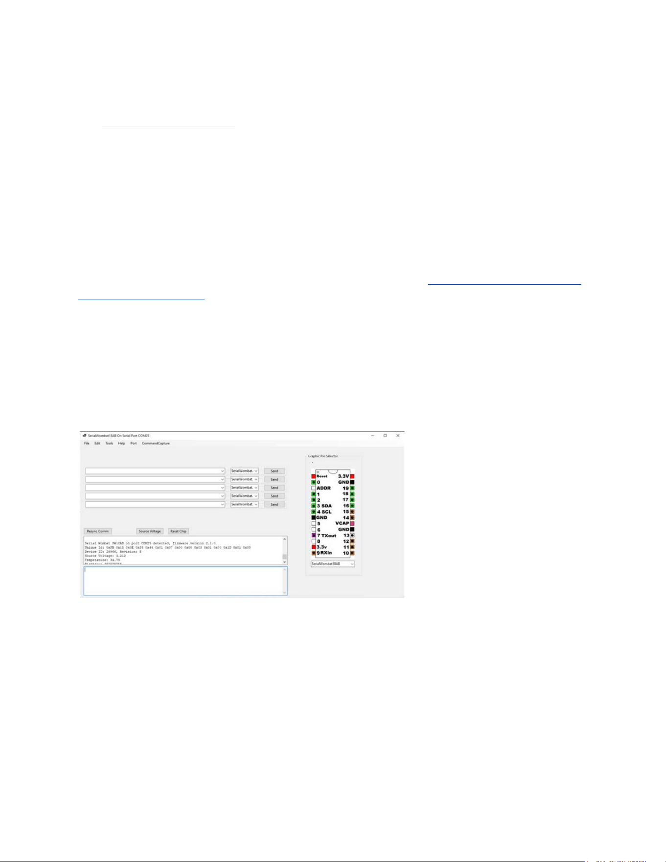
Serial Wombat Panel Application
The Serial Wombat C# library includes a sample application called Serial Wombat Panel
Application. This application uses .Net Windows Forms for its GUI and therefore is only
compatible with Windows.
The Serial Wombat Panel Application provides an easy way to experiment with Serial Wombat
18AB features. The Serial Wombat Panel application is designed to interface to a Serial
Wombat Chip over UART. It is also possible to interface to a Serial Wombat Chip over I2C if a
UART to I2C bridge program is used on an Arduino or Micropython board.
The Serial Wombat Panel Application can be used to help debug Serial Wombat applications
running over I2C by simultaneously connecting to the UART. See Simultaneous UART and I2C
interfacing from 2 Hosts .
Launch the application either through Visual Studio or by double clicking the .exe file in the
SerialWombatCsharpLib\WombatPanelWindowsForms\bin\Debug\net6.0-windows\WombatPan
elWindowsForms.exe
Location.
Use the Port…Open Serial menu item to connect to the Serial Wombat chip.
A successful connection will result in a reading of the Serial Wombat chip’s firmware version
and other information.
Pins can be configured by right clicking them and selecting the desired pin mode:
Serial Wombat 18AB Chip User Guide Page 110 of 119
V2.1.0_A
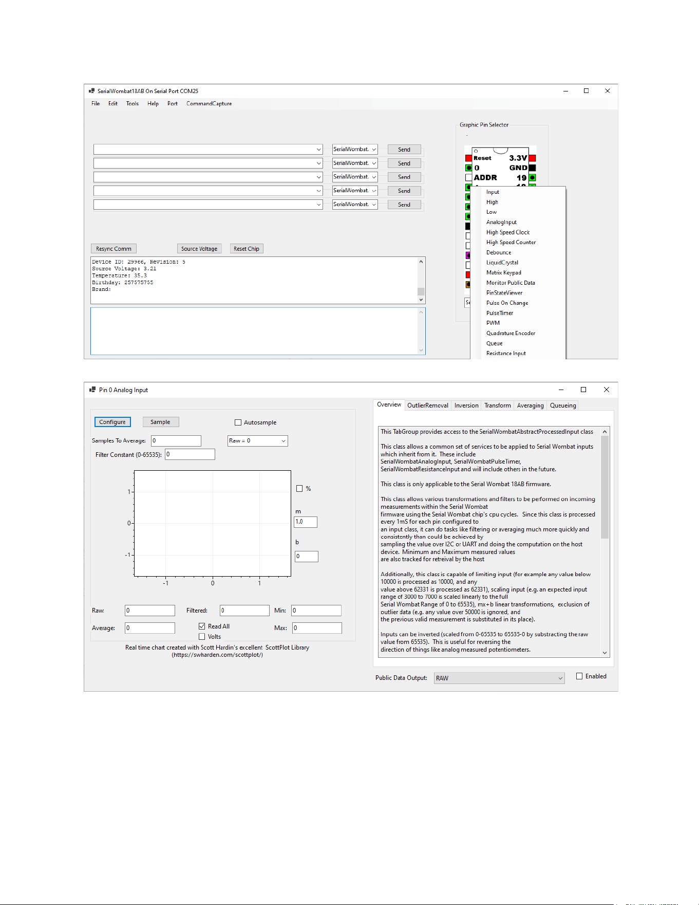
The public data of a pin or public data source can be monitored by right clicking a pin and
selecting Monitor Public Data. Clicking the Autosample box will cause continuous requests to
be sent for that piece of data.
Serial Wombat 18AB Chip User Guide Page 111 of 119
V2.1.0_A
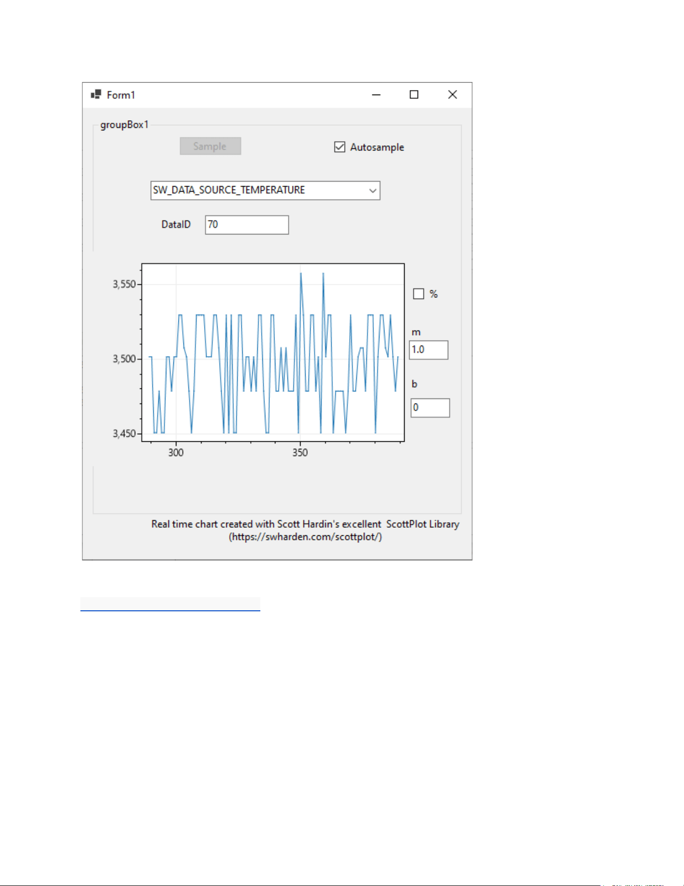
Protocol Analyzer
A protocol analyzer is available to monitor and decode Serial Wombat commands sent over an
I2C or UART bus. This analyzer runs on top of the Saleae Logic software package and is
available for download through that application. This tool can be useful in debugging projects
that include the Serial Wombat 18AB chip.
A video is available here:
https://youtu.be/cL7kUm9qjvU
Serial Wombat 18AB Chip User Guide Page 114 of 119
V2.1.0_A
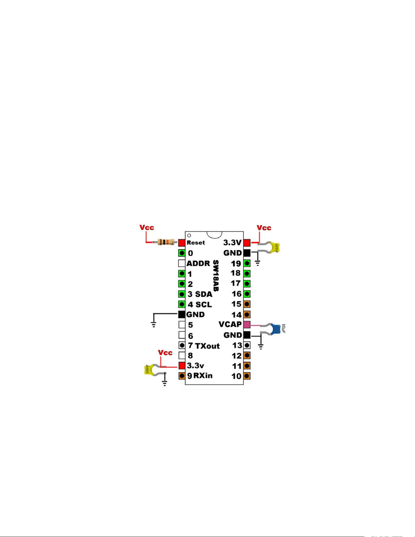
Troubleshooting
Step 1: Check the basics
General Stuff:
● Make sure your chip has a stable, in-range power supply and that the included
capacitors are attached across the power and ground pins. If you can, verify power
voltage using a multimeter
● Make sure your chip is connected properly. Ensure that the chip is in the proper
orientation (power pins are near the notch) and that both100uF capacitors are
connected across Vdd and GND.
● Make sure the 10k reset resistor is providing voltage to the reset pin (measure it with a
multimeter)
● Make sure the 10uF capacitor is connecting the Vcap pin to ground.
● Disconnect any loads (such as motors, servos, or relays) from your circuit. Frequently
these devices can sufficiently disrupt the power supply such that the Serial Wombat 4B
chip’s internal low-voltage-reset circuit triggers. It is suggested that inductive loads not
be driven directly from the same supply driving logic portions of the circuit.
● If you’re using a decal on the Serial Wombat chip, is it oriented in the correct direction?
Make sure the black notch at one end of the decal matches up with the black dot on the
chip
Serial Wombat 18AB Chip User Guide Page 115 of 119
V2.1.0_A

● Make sure you’re using the latest Arduino / C# / Python library. It’s possible your issue is
fixed in a newer version than you have
● In Arduino, consider registering the default error handler. This provides helpful
information (particularly on the 18AB) about configuration errors.
I2C related Stuff
● Make sure you’re talking to the correct address. The address the Serial Wombat 18AB
chip responds to depends on the configuration of the address pin (see Circuit
Construction )
● If connected using I2C, make sure you have pull up resistors on SCL and SDA (don’t
rely on internal pull ups on your chip, they’re typically out of spec for I2C).
● Make sure your SDA line from the Arduino or other host is attached to the SDA line on
the Serial Wombat Chip. Same for SCL. Did you accidentally cross them?
● Make sure you have the correct pins assigned on your Arduino or MicroPython board.
The begin or initialization call for I2C communications allows you to specify which pins
are being used on many platforms. The examples included with the library may assume
different I2C pins on the host than what you are using due to variation between boards.
● Does the Serial Wombat chip finder sketch in the Arduino Examples / Serial Wombat
directory find the Serial Wombat chip? This should always work if your hardware is
setup correctly
● In your sketch, do you call begin on Wire then on the Serial Wombat chip?
● Can you verify proper I2C traffic operation using a Logic analyzer? See this video for a
cheap way to do this. https://youtu.be/cL7kUm9qjvU
UART Related Stuff
● Make sure you are connected to the correct UART port.
● Make sure that the ADDR pin of the Serial Wombat 18AB chip is grounded. It needs to
be grounded at powerup. Grounding it after power is applied will result in the chip
operating in I2C mode
● Make sure you are opening the port using 115200 / 8 / N / 1 / No Flow Control settings
● Double check that your RX and TX connections are correct. Try swapping them
● If connecting from an Arduino or MicroPython board ensure that you’re connecting the
proper pins from the board to the Serial Wombat Chip. Some boards require the UART
pins to be declared in the initialization or begin of the UART.
Serial Wombat 18AB Chip User Guide Page 116 of 119
V2.1.0_A

Step 2: Check the YouTube video and comments
Go to the Broadwell Consulting Inc. YouTube channel and take a look at the Serial Wombat
playlist. Watch the video for the task you’re trying to achieve, and check the comments to see if
any other users have asked a question about your issue.
If not, then leave a comment with your question on the video that best matches what you’re
trying to do.
Serial Wombat 18AB Chip User Guide Page 117 of 119
V2.1.0_A

Additional Resources:
YouTube
The Broadwell Consulting Inc. YouTube Channel has many helpful tutorial Videos which walk
through how to use the various Serial Wombat chip pin modes and features.
Arduino Library
The Serial Wombat Arduino Library supports the Serial Wombat 4B and Serial Wombat
18AB chips.
The library documentation is available on github.io . Click on the classes tab to see
documentation and interfaces for individual pin modes.
The Serial Wombat Arduino Library is available on GitHub . This is a good place to log
an issue if you find a bug in the Arduino library or want to request new features. Please
don’t use the issue system for support requests.
Serial Wombat 18AB firmware
The Serial Wombat 18AB firmware documentation and protocol documentation are
available on github.io .
The Serial Wombat 18AB firmware source code is available on GitHub .
Support and Technical Assistance
If the above troubleshooting and guides don’t solve your problem, contact Broadwell Consulting
at [email protected] for support. Support requests sent in over email may take a couple
of days to respond. Priority is given to questions asked in public forums such as on the
YouTube channel so that others can benefit from the answers. Please include the results of the
troubleshooting steps above in your support request. Otherwise, the first response may be a
request for the results of those steps, slowing down the process.
Serial Wombat 18AB Chip User Guide Page 118 of 119
V2.1.0_A

Revision History
Version
Changes
V2.1.0_A
Initial Version
Serial Wombat 18AB Chip User Guide Page 119 of 119
V2.1.0_A