1
Outdoor Lifestyles by Hearth & Home Technologies • Lanai 48/60 Installation Manual • 4111-901 Rev. I • 06/23
Installation Manual
Installation and appliance setup
INSTALLER: Leave this manual with the appliance.
CONSUMER: Retain this manual for future reference.
NOTICE: DO NOT discard this manual!
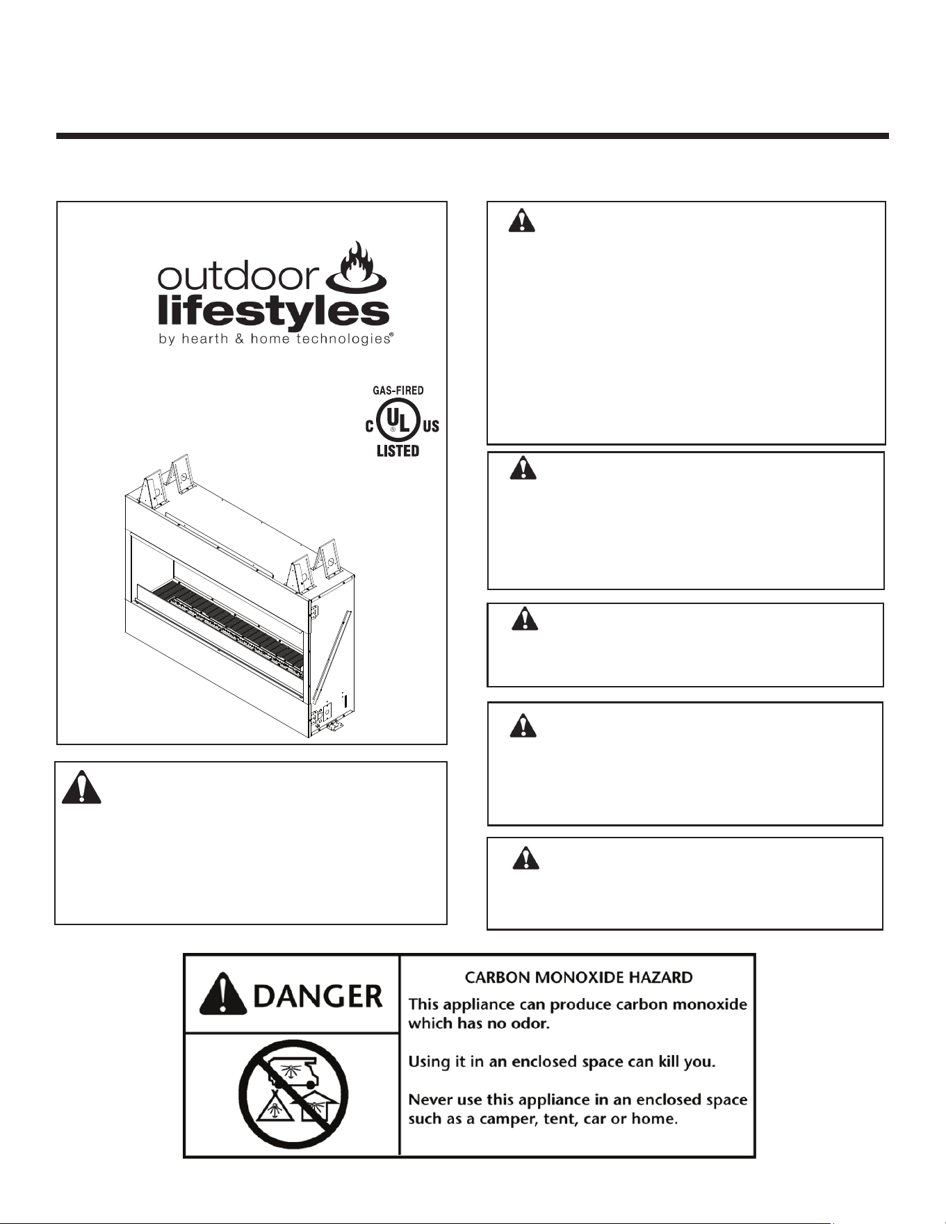
Model:
WARNING! Risk Of Fire!
Do not install glass doors
on this appliance.
Glass doors could cause overheating
of adjacent structures.
DANGER
FIRE OR EXPLOSION HAZARD
If you smell gas:
• Shut off gas to the appliance.
• Extinguish any open ame.
• If odor continues, leave the area immediately.
• After leaving the area, call your gas supplier or re
department.
• Failure to follow these instructions could result in re
or explosion, which could cause property damage,
personal injury, or death.
WARNING
Do not store or use gasoline or other ammable va-
pors and liquids in the vicinity of this or any other
appliance
An LP-cylinder not connected for use shall not be
stored in the vicinity of this or any other appliance.
WARNING: For outdoor use only.
Installation and service must be performed by a qual-
ied installer, service agency, or the gas supplier.
WARNING: Improper installation, adjust-
ment, alteration, service or maintenance can cause
injury or property damage. Read the installation,
operating and maintenance instructions thoroughly
before installing or servicing this equipment.
WARNING: If the information in this manual
is not followed exactly, a re or explosion may
result causing property damage, personal injury, or
loss of life.
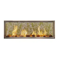
ODLANAIG-48
ODLANAIG-60
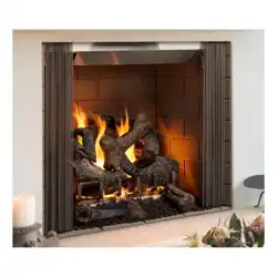
MH61458

2
Outdoor Lifestyles by Hearth & Home Technologies • Lanai 48/60 Installation Manual • 4111-901 Rev. I • 06/23
Safety Alert Key:
• DANGER! Indicates a hazardous situation which, if not avoided will result in death or serious injury.
• WARNING! Indicates a hazardous situation which, if not avoided could result in death or serious injury.
• CAUTION! Indicates a hazardous situation which, if not avoided, could result in minor or moderate injury.
• NOTICE: Used to address practices not related to personal injury.
Table of Contents
Standard Work Checklist .................................3
1 Product Specic Information
A. Appliance Certication ................................4
B. BTU Specications .....................................4
C. High Altitude Installations ...........................4
D. Non-combustible Materials Specication ...4
E. Combustible Materials Specication ..........4
F. Electrical Codes .........................................4
G. Fuel ............................................................4
2 Getting Started
A. Design and Installation Considerations ......5
B. Tools and Supplies Needed ........................5
C. Inspect Appliance and Components ........... 6
3 Framing and Clearances
A. Appliance Dimension/Weights Diagrams ...7
B. Clearances to Combustibles ......................8
C. Vent Minimum Clearances ....................... 11
D. Hearth Extension/Floor Protection ...........12
E. Stand-Alone Installation ...........................12
F. Moisture Resistance ................................. 13
4 Appliance Preparation
A. Securing and Leveling Appliance .............14
B. Flashing .................................................... 14
5 Electrical Information
A. Wiring Requirements ................................ 15
B. IntelliFire Pilot Ignition System Wiring ......15
C. Installing the Electrical ..............................15
D. Wall Switch Control Assembly ..................18
6 Gas Information
A. Valve Access ............................................19
B. Gas Pressure ...........................................19
C. Gas Connection ........................................20
D. Fuel Conversion .......................................20
E. High Altitude Installations .........................20
7 Finishing
A. Facing Material ......................................... 21
8 Appliance setup
A. Remove the Shipping Materials ...............23
B. Clean the Appliance .................................23
C. Optional Accessories ................................ 23
D. Verify Pilot Shield .....................................23
E. Install Deection Glass ............................. 23
F. Install Clear Crystal Media .......................23
G. Remove Media Placement Template ........ 23
9 Reference Materials
A. Accessories ..............................................24
B. Addendum ................................................25
►
3
Outdoor Lifestyles by Hearth & Home Technologies • Lanai 48/60 Installation Manual • 4111-901 Rev. I • 06/23
Standard Work Checklist
Attention Installer:
Follow this Standard Work Checklist
This standard work checklist is to be used by the installer in conjunction with, not instead of, the instructions contained in this installation
manual
Customer: Date Installed: _________________________
Lot/Address Location of
_________________________
Installer _________________________
Dealer/Distributor Phone # _________________________
Model
________________________
______________________ __
________________________
________________________
ODLANAIG-48
ODLANAIG-60
Serial # _________________________
Appliance Install Section 3 & 4
YES IF NO, WHY?
Required non-combustible board is installed. ________________________________________
clearances to combustibles. ________________________________________
Fireplace is leveled and secured. ________________________________________
Electrical Section 5
Unswitched power (110-120Vac.) provided to the
appliance. ________________________________________
Switch wires properly installed. ________________________________________
Gas Section 6
Proper appliance for fuel type. ________________________________________
Was a conversion performed? ________________________________________
Leak check performed and inlet pressure
________________________________________
Finishing Section 7
Combustible materials not installed in
non-combustible areas. ________________________________________
all clearances meet installation manual
requirements. ________________________________________
Mantels and wall projections comply with installation
manual requirements. ________________________________________
________________________________________
________________________________________
________________________________________
Appliance Setup Section 8
All packaging and protective materials removed
(inside and outside of appliance)
Media installed correctly.
Optional screen or trim kit properly installed.
Manual bag and all of its contents are removed from
inside/under the appliance and given to party
responsible for use and operation. ________________________________________
Started appliance and
no gas leak exists. ________________________________________
Hearth & Home Technologies recommends the following:
• Photographing the installation and copying this checklist for your .
• That this checklist remain visible at all times on the appliance until the installation is complete.
Comments: Further description of the issues, who is responsible (Installer/Builder/Other trades, etc.) and corrective action
needed___________________________________________________________________________________________
_________________________________________________________________________________________________
_________________________________________________________________________________________________
Comments Communicated to party responsible __________________ by ________________ on __________________
(Builder/Gen. Contractor) (Installer) (Date)
WARNING! Risk of Fire or Explosion! Failure to install appliance according to these
4111-982A 2/20
4
Outdoor Lifestyles by Hearth & Home Technologies • Lanai 48/60 Installation Manual • 4111-901 Rev. I • 06/23
1
Product Specic Information
A. Appliance Certication
This product is listed to ANSI standards for
“Outdoor Decorative Gas Appliances” and “Gas
Fired Appliances for Use at High Altitudes”.
Notice: This installation must conform with local
codes. In the absence of local codes you must
comply with the National Fuel Gas Code, ANSI
Z223.1- latest edition in the U.S.A. and the CAN/
CGA B149 Installation codes in Canada.
When an appliance is connected to a xed piping
system, the installation must conform with local
codes, or in the absence of local codes with the
National Fuel Gas Code, ANSI Z223.1/NFPA
54, or International Fuel Gas Code.
B. BTU Specications
C. High Altitude Installations
Notice: If the heating value of the gas has been
reduced, these rules do not apply. Check with your
local gas utility or authorities having jurisdiction.
When installing above 2000 feet elevation:
• In the USA: reduce input rate 4% for each
1000 feet above 2000 feet.
• In CANADA: Input ratings are certied without
a reduction of input rate for elevations up to
4500 feet (1350m) above sea level. Please
consult provincial and/or local authorities
having jurisdiction for installations at elevations
above 4500 feet (1370m.)
Check with your local gas utility to determine
proper orice size.
D. Non-combustible Materials
Specication
Material which will not ignite and burn. Such
materials are those consisting entirely of steel,
iron, brick, tile, concrete, slate, glass, plasters or
any combination thereof.
Materials that are reported as passing ASTM E
136, Standard Test Method for Behavior of
Materials in a Vertical Tube Furnace at 750 °C
shall be considered non-combustible materials.
E. Combustible Materials Specication
Materials made of or surfaced with wood,
compressed paper, plant bers, plastics, or other
material that can ignite and burn, whether ame
proofed or not, or plastered or unplastered shall
be considered combustible materials.
F. Electrical Codes
Notice: This appliance must be electrically wired
and grounded in accordance with local codes
or, in the absence of local codes, with National
Electric Code ANSI/NFPA 70-latest edition or
the Canadian Electrical Code CSA C22.1.
• A 110-120Vac. circuit for this product must be
protected with ground-fault circuit-interrupter
protection, in compliance with the applicable
electrical codes.
G. Fuel
This appliance must not be used to burn solid fuel.
When an appliance is connected to a xed piping
system, the installation must conform with local
codes, or in the absence of local codes with the
National Fuel Gas Code, ANSI Z223.1/NFPA
54, or International Fuel Gas Code.
Model: ODLANAIG-48/ODLANAIG-60
Laboratory: Underwriters Laboratories (UL)
Type: Outdoor Decorative Gas Appliances
Standard: ANSI Z21.97-2017, CSA 2.41-2017
WARNING: This product and the
fuels used to operate this product (liquid
propane or natural gas), and the products of
combustion of such fuels, can expose you to
chemicals including benzene, which is known
to the State of California to cause cancer and
reproductive harm. For more information go
to: www.P65Warnings.ca.gov.
Model Gas Type
Max Input
BTU Orice Size
ODLANAIG-48
Natural 55,000 #26 (.147)
Propane 55,000 # 42 (.093)
ODLANAIG-60
Natural 65,000 #23 (.154)
Propane 65,000 #39 (.099)
5
Outdoor Lifestyles by Hearth & Home Technologies • Lanai 48/60 Installation Manual • 4111-901 Rev. I • 06/23
2
Getting Started
A. Design and Installation Considerations
The Lanai series gas appliance is designed for
outdoor use and may be installed as a stand alone
appliance or built into a wall.
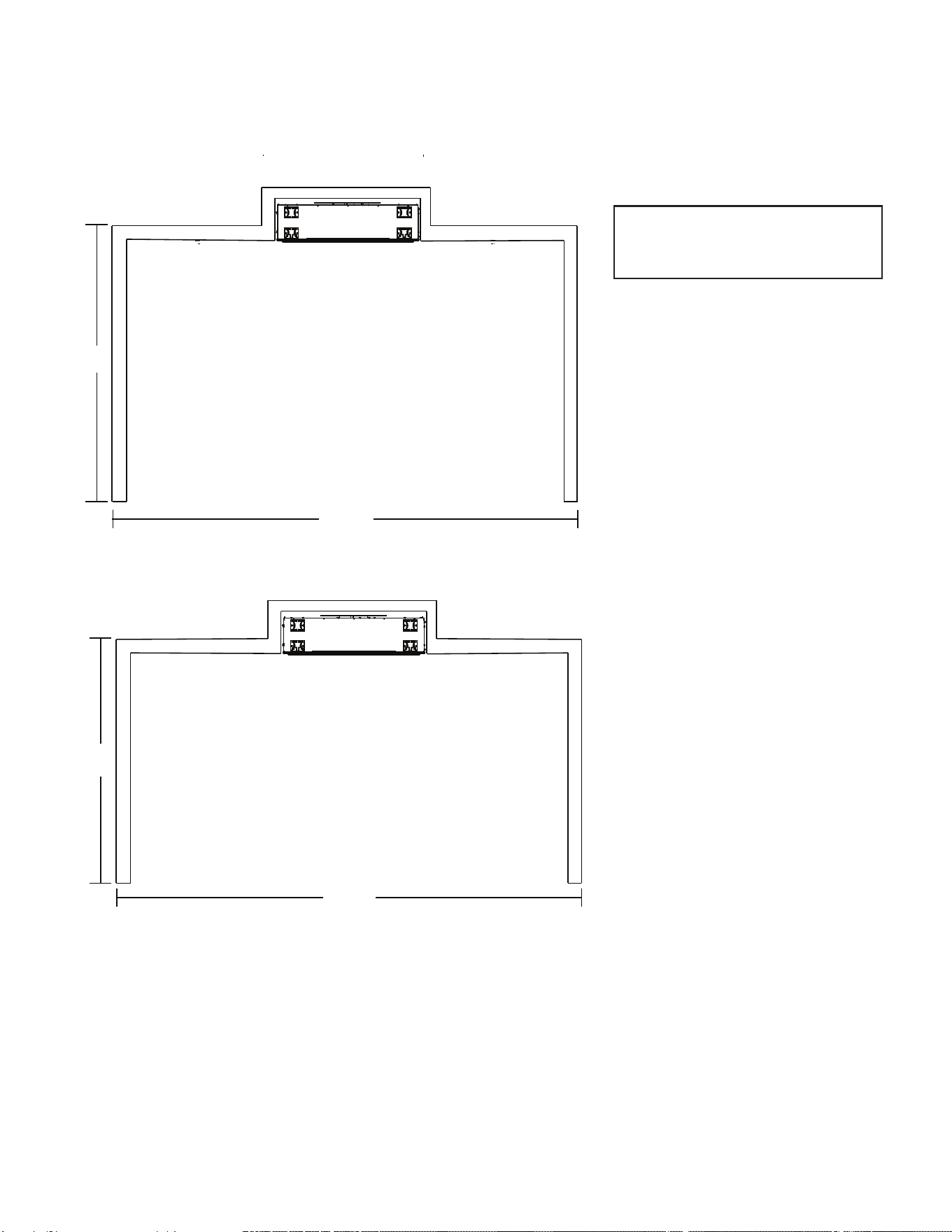
Outdoor spaces - For the purpose of these
instructions, an appliance is considered to be
outdoors if installed with shelter no more inclusive
than:
1. With walls on all sides, but no overhead cover
2. Within a partial enclosure which includes an
overhead cover and no more than two side
walls. These side walls may be parallel, as in
a breezeway, or at right angles to each other;
or
3. Within a partial enclosure which includes an
overhead cover and three sidewalls, as long
as 30 % or more of the horizontal periphery
of the enclosure is permanently open. See
Addendum on page 25.
NOTE: Screen may be used on the open sides
of the shelter. 14x18 and 16x18 screen mesh is
approved for use. DO NOT use solar screen or
no-see-um screen.
Install on wood, composite or non-combustible
continuous at surface, extending full width and
depth of the appliance to prevent damage.
Refer to section three for clearances.
Installation MUST comply with local, regional,
state and national codes and regulations. Consult
the authorities having jurisdiction over restrictions,
installation inspection and permits.
Before installing, determine the following:
• Where the appliance is to be installed.
– Clearances to side walls.
– Location of indoor appliance terminations,
air inlets, gas meters, etc.
– Location of the appliance to a door that
swings open to ensure it doesn’t interfere
with the appliance when opened
– Location of Windows.
– Location of Walkways.
– Possibility of ooding or running water.
• Gas supply piping requirements.
• Electrical wiring requirements.
• Framing and nishing details.
B. Tools and Supplies Needed
Before beginning the installation be sure that the
following tools and building supplies are available.
Tape Measure Framing material
Pliers Hammer
Phillips screwdriver Manometer
Gloves Framing square
Voltmeter Electric drill and bits (1/4in)
Plumb line Safety glasses
Level Reciprocating saw
3/4 inch wrench Crescent wrench
7/8 inch wrench 1/4 inch nut driver
7/16 inch wrench pipe sealant
Flat head screwdriver
Non-corrosive leak check solution
1/2 - 3/4 inch length, #6 or #8 Self-drilling screws
Caulking material (300°F Minimum continuous
exposure rating.)
Installation and service of this
appliance should be performed
by qualied personnel. Hearth &
Home Technologies recommends
HHT Factory Trained or NFI
certied professionals
Improper installation, adjustment, alteration,
service or maintenance can cause injury or
property damage. For assistance or additional
information, consult a qualied service
technician, service agency or your dealer.
NOTE: Installation and repair should be done by
a qualied service person. The appliance should
be inspected before use and at least annually by a
qualied service person. More frequent cleaning
may be required as necessary. It is imperative that
the control compartment, burners, and circulating
air passageways of the appliance are kept clean.

6
Outdoor Lifestyles by Hearth & Home Technologies • Lanai 48/60 Installation Manual • 4111-901 Rev. I • 06/23
C. Inspect Appliance and Components
• Carefully remove the appliance and
components from the packaging.
• Remove deection glass and packaging from
inside of appliance.
• Remove crystal media which is packaged
separately and located inside of the appliance.
• Remove wall control which is packaged
separately and located inside of the appliance.
• Remove protective coating.
• Report any components damaged in shipping
to your dealer.
• Read all of the instructions before starting the
installation. Follow these instructions carefully
during the installation to ensure maximum
safety and benet.
WARNING! Risk of Fire or Explosion! Damaged
parts could impair safe operation. DO NOT install
damaged, incomplete or substitute components.
Hearth & Home Technologies disclaims any
responsibility for, and the warranty will be
voided by, the following actions:
• Installation and use of any damaged
appliance.
• Modication of the appliance.
• Installation other than as instructed by
Hearth & Home Technologies.
• Improper positioning of the media.
• Installation and/or use of any component
part not approved by Hearth & Home
Technologies.
Any such action may cause a re hazard.
WARNING! Risk of Fire, Explosion or Electric
Shock!
DO NOT use this appliance if any part has been
under water. Call a qualied service technician to
inspect the appliance and to replace any part of
the control system and/or gas control which has
been under water. DO NOT use this appliance if
any of the media area is contaminated with snow
or debris.
7
Outdoor Lifestyles by Hearth & Home Technologies • Lanai 48/60 Installation Manual • 4111-901 Rev. I • 06/23
3
Framing and Clearances
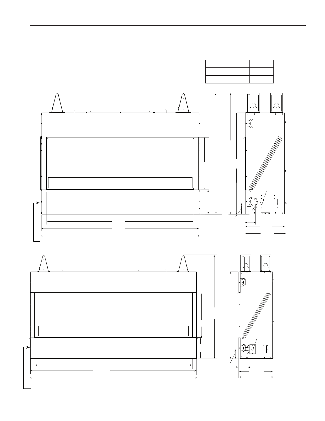
A. Appliance Dimension/Weights Diagrams
Dimensions are actual appliance dimensions. Use for reference only. For framing dimensions and
clearances refer to Figure 3.2 and Figure 3.3.
Figure 3.1. Appliance Dimensions – ODLANAIG-48/60
39-1/2 in.
(1003 mm)
17 in.
(432 mm)
8-1/8 in.
(206 mm)
47-7/8 in.
(1216 mm)
51-1/4 in.
(1302 mm)
52-1/8 in.
(1324 mm)
39-1/2 in.
(1003 mm)
33-1/8 in.
(841 mm)
13-3/8 in.
(340 mm)
13 in.
(330 mm)
3-1/2 in.
(89 mm)
3-5/8 in.
(92 mm)
120VAC Access
Gas Access Left Side
64-1/8 in.
(1629 mm)
63-1/4 in.
(1607 mm)
60 in.
(1524 mm)
39-1/2 in.
(1003 mm)
17 in.
(432 mm)
8-1/8 in.
(206 mm)
33-1/8 in.
(841 mm)
3-5/8 in.
(92 mm)
3-1/2 in.
(89 mm)
13-3/8 in.
(340 mm)
13 in.
(330 mm)
120VAC
Access
Gas Access Left Side
Model Pounds
ODLANAIG-48 215
ODLANAIG-60 245
ODLANAIG-48
ODLANAIG-60
Appliance Weights

8
Outdoor Lifestyles by Hearth & Home Technologies • Lanai 48/60 Installation Manual • 4111-901 Rev. I • 06/23
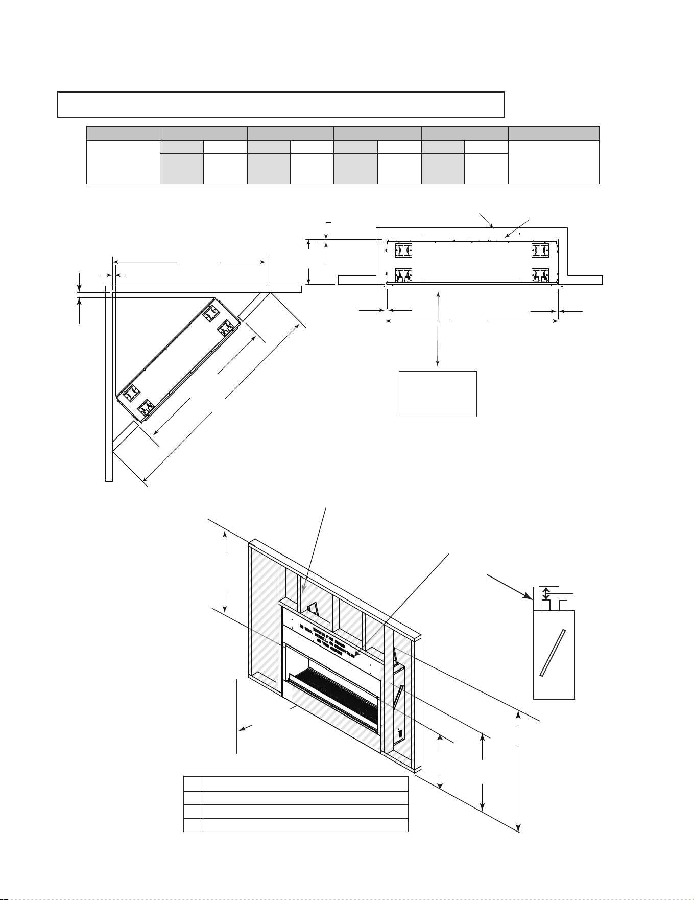
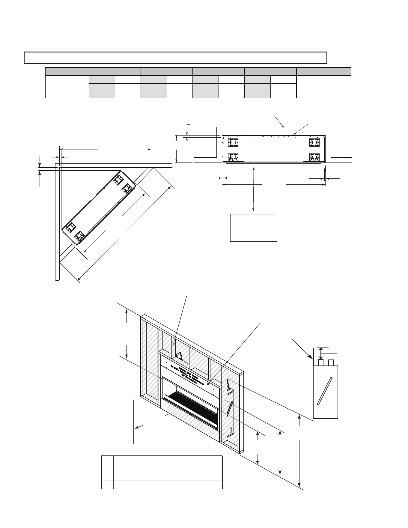
B. Clearances to Combustibles
When selecting a location for the appliance, it is
important to consider the required clearances to
walls (see Figures 3.2, 3.3, and 3.4.)
WARNING! Risk of Fire or Burns! Provide
adequate clearance around air openings and for
service access. Due to high temperatures, the
appliance should be located out of trafc and
away from furniture and draperies.
WARNING! Risk of Fire or Burns! The appliance
is hot and wind may cause ames to reach out
in front.
• Be sure to install eyebrow in the top of the
opening before using appliance.
• Keep furniture, draperies and other
combustibles away.
• Locate the appliance away from trafc areas.
• Clean up fallen leaves, branches and other
combustible materials before using the
appliance.
• See Figure 3.2, 3.3 and 3.4 for required
clearances.
• Install on wood, composite or non-combustible
continuous at surface, extending full width
and depth of the appliance to prevent damage.
WARNING! Risk of Fire! Maintain specied air
space clearances to appliance:
• Insulation and other materials must be secured
to prevent accidental contact.
• The chase/enclosure must be properly
blocked to prevent blown insulation or other
combustibles from entering and making
contact with the appliance.
• Failure to maintain air space may cause
overheating and a re.
9
Outdoor Lifestyles by Hearth & Home Technologies • Lanai 48/60 Installation Manual • 4111-901 Rev. I • 06/23
Note: If this surface is
inside the building’s
warm air envelope...
...then this surface
must be an exterior
wall system.
1/2 in.
(13 mm)
1/2 in.
(13 mm)
52-3/4 in.
(1340 mm)
1/2 in.
(13 mm)
13-3/8 in.
(340 mm)
1/2 in.
(13 mm)
Combustible materials
allowed in shaded areas
78-1/4 in.
(1988 mm)
*39 in. min.
(990 mm)
to ceiling
Combustible Object
36 in.
(914 mm)
8” Cement Board (supplied for
minimum height installations)
Extends above minimum
framing dimensions.
33-1/4 in.
(844 mm)
*Measured from top
of firebox opening
25 in.
(635 mm)
55-3/8 in.
(1407 mm)
39-3/4 in.
(1009 mm)
52-3/4 in.
(1340 mm)
1-1/2 in.
(38 mm)
D
A
B
C
A
Bottom of appliance to top of opening
B Bottom of appliance to bottom of cement board
C
D
Bottom of appliance to top of standoff
Top of standoff to top of cement board
MODEL FRONT WIDTH BACK WIDTH HEIGHT DEPTH VIEWING AREA
ODLANAIG-48
Actual Framing Actual Framing Actual Framing Actual Framing
47-7/8" x 17"
[1216 x 432]
52-1/8"
[1324]
52-3/4"
[1340]
52-1/8"
[1324]
52-3/4"
[1340]
39-1/2"
[1003]
39-3/4"
[1009]
13-3/8"
[340]
13-3/8"
[340]
36 in. minimum
(914 mm)
to combustible
object
1/2 in.
(13 mm)
Notice: Flash the perimeter of the appliance, corners
and the appliance face in a manner consistent with
regional practices as required to prevent water
penetration around the appliance. See Section 3.F.
for more information regarding wall and enclosure
construction.
Notice: Vinyl siding must
not be placed between the
appliance opening and the
ceiling/overhang.
Note: For actual appliance dimensions refer to Section 3.A.
Figure 3.2. Appliance Locations and Framing Dimensions - ODLANAIG-48
ODLANAIG-48
NOTICE: Illustrations reect typical installations and are FOR DESIGN PURPOSES ONLY. Illustrations/
diagrams are not drawn to scale. Actual installation may vary due to individual design preference.
10
Outdoor Lifestyles by Hearth & Home Technologies • Lanai 48/60 Installation Manual • 4111-901 Rev. I • 06/23
ODLANAIG-60
NOTICE: Illustrations reect typical installations and are FOR DESIGN PURPOSES ONLY. Illustrations/
diagrams are not drawn to scale. Actual installation may vary due to individual design preference.
Note: For actual appliance dimensions refer to Section 3.A.
Figure 3.3. Appliance Locations and Framing Dimensions - ODLANAIG-60
Note: If this surface is
inside the building’s
warm air envelope...
...then this surface
must be an exterior
wall system.
1/2 in.
(13 mm)
1/2 in.
(13 mm)
64-3/4 in.
(1645 mm)
1/2 in.
(13 mm)
13-3/8 in.
(340 mm)
1/2 in.
(13 mm)
Combustible materials
allowed in shaded areas
64-3/4 in.
(1645 mm)
90-3/8 in.
(2296 mm)
*39 in. min.
(990 mm)
to ceiling
Combustible Object
36 in.
(914 mm)
12” Cement Board (supplied for
minimum height installations)
Extends above minimum
framing dimensions.
33-1/4 in.
(844 mm)
*Measured from top
of firebox opening
25 in.
(635 mm)
63-7/8 in.
(1622 mm)
39-3/4 in.
(1009 mm)
5-1/2 in.
(140 mm)
A
B
C
A
Bottom of appliance to top of opening
B Bottom of appliance to bottom of cement board
C
D
Bottom of appliance to top of standoff
Top of standoff to top of cement board
MODEL FRONT WIDTH BACK WIDTH HEIGHT DEPTH VIEWING AREA
ODLANAIG-60
Actual Framing Actual Framing Actual Framing Actual Framing
60" x 17"
[1524 x 432]
64-1/8"
[1629]
64-3/4"
[1645]
64-1/8"
[1629]
64-3/4"
[1645]
39-1/2"
[1003]
39-3/4"
[1009]
13-3/8"
[340]
13-3/8"
[340]
36 in. minimum
(914 mm)
to combustible
object
1/2 in.
(13 mm)
Notice: Flash the perimeter of the appliance, corners
and the appliance face in a manner consistent with
regional practices as required to prevent water
penetration around the appliance. See Section 3.F
and 4.B for more information regarding wall and
enclosure construction.
Notice: Vinyl siding must
not be placed between the
appliance opening and the
ceiling/overhang.
D
11
Outdoor Lifestyles by Hearth & Home Technologies • Lanai 48/60 Installation Manual • 4111-901 Rev. I • 06/23
U.S.A. CANADA
A Clearance above grade,veranda, porch, deck, or balcony 0 in. (0 cm) 0 in. (0 cm)
B
Clearance to window or door that may
be opened, or to permanently closed
window
Non-vinyl 12 in. (305 mm) 12 in. (305 mm)
Vinyl 24 in. (610 mm) 24 in. (610 mm)
C
clearance below unventilated soft 39 in. (990 mm) 39 in. (990 mm)
clearance below ventilated soft 39 in. (990 mm) 39 in. (990 mm)
clearance below any vinyl softs and electrical service 60 in. (1524 mm) 60 in. (1524 mm)
D clearance to outside corner 9 in. (229 mm) 9 in. (229 mm)
E clearance to inside corner
Non-vinyl siding (1 side) 4 in. (102 mm) 4 in. (102 mm)
Non-Vinyl siding (Alcove) 8 in. (203 mm) 8 in. (203 mm)
Vinyl siding & windows 48 in. (1219 mm) 48 in. (1219 mm)
F
not to be installed above a gas meter/regulator assembly within 3 feet horizontally from
the center-line of the regulator
3 ft (914 mm) 3 ft (914 mm)
G clearance to gas service regulator vent outlet 3 ft (914 mm) 3 ft (914 mm)
H
clearance to non-mechanical air supply inlet to building or the combustion air inlet to
any other appliance termination (mechanical or non-mechanical)
12 in. (305 mm) 12 in. (305 mm)
I
clearance to a mechanical (powered) air supply inlet
***(All mechanical air intakes within 10 feet of a horizontal termination cap must be
a minimum of 3 feet below termination.)
3 ft (914 mm)*** 6 ft (1829 mm)
J
For appliances installed facing or opening onto public property or property servicing
more than one single family dwelling, such as driveways, sidewalks, etc. refer to local
building codes/regulations for proper clearances.
Refer to local
codes
Refer to local
codes
K
clearance from sides of electrical service 24 in. (610 mm) 24 in. (610 mm)
Location of the vent termination must not interfere with access to the electrical service.
L
clearance above electrical service 12 in. (305 mm) 12 in. (305 mm)
Location of the vent termination must not interfere with access to the electrical service.
M
clearance under veranda, porch, deck, balcony or overhang
(Permitted only if the area meets the requirements of an outdoor space as dened in section
2.A “Design and Installation Considerations”)
39 in. (990 mm) 39 in. (990 mm)
vinyl or composite overhang 72 in. (1829 mm) 72 in. (1829 mm)
C
J
B
D
B
F
B
A
E
FP
M
H or i
G
X
H
A
H
FP
FP
FP
FP
FP
FP
FP FP
FP
X
= AIR SUPPLY INLET
= Appliance OPENING
= AREA WHERE TERMINAL IS NOT PERMITTED
Electrical
Service
K
FP
FP
K
FP
L
C
FP
U.S.A. Installations: In accordance with the current ANSI Z223.1/NFPA 54, National Fuel Gas Code.
Canadian Installations: In accordance with the current CSA B149.1, Natural Gas and Propane Installation Code.
FP
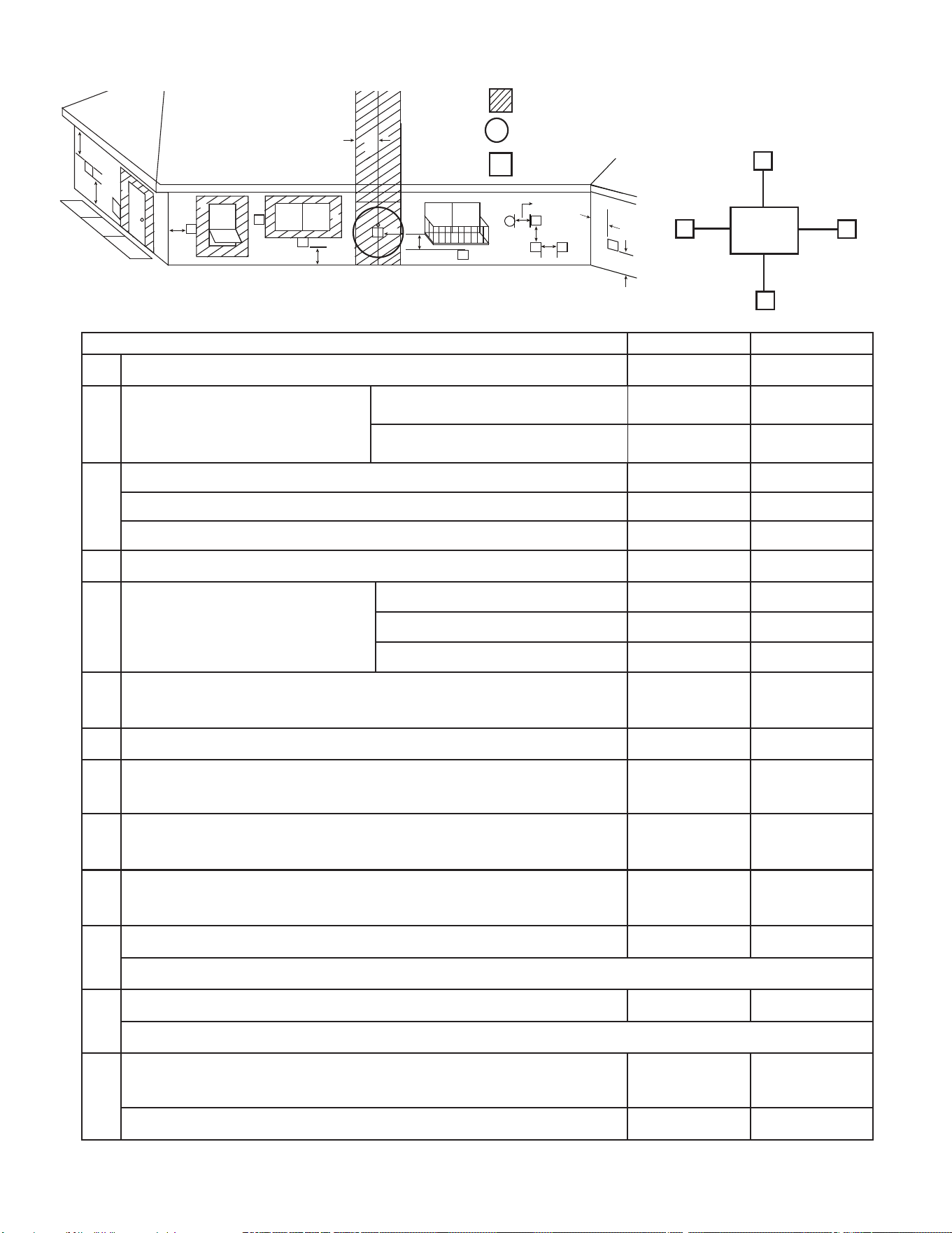
Figure 3.4 Minimum Clearances
C. Vent Minimum Clearances
12
Outdoor Lifestyles by Hearth & Home Technologies • Lanai 48/60 Installation Manual • 4111-901 Rev. I • 06/23
WARNING! Risk of Fire! Comply with all minimum
clearances to combustibles as specied. Framing
or nishing material closer than the minimums
listed must be constructed entirely of non-
combustible materials (i.e., steel studs, concrete
board, etc).
D. Hearth Extension/Floor Protection
This application does not require a hearth
extension.
E. Stand-Alone Installation
This appliance may be installed as a stand-
alone appliance.
• Construct a stand-alone framing of combustible
or noncombustible materials.
• Cement board or other noncombustible
material can be applied directly to the face of
the appliance.
• Tape and seal all joints and corners.
• Provide proper ashing and moisture
management if installed on surfaces that may
rot or otherwise be damaged by water. (See
also Section 4.B.)
• Built-in Installation
When this appliance is installed into a wall, we
recommend that the wall be an exterior wall
system.
• See framing measurements in Figure 3.2 and 3.3.
• You must maintain
11
⁄22 in. air space at the back
and sides.
• The header must not be placed below the top
of the top standoffs.
• Noncombustible wall sheathing material is
required above the appliance. (See Figure 3.4
and 3.5)
• A cement board has been provided for this
installation.
Flash the perimeter of the appliance, corners and
the appliance face in a manner consistent with
regional practices as required to prevent water
penetration around the appliance. See Section
3B and Figure 3.2 and 3.3 for more information
regarding wall and enclosure construction.
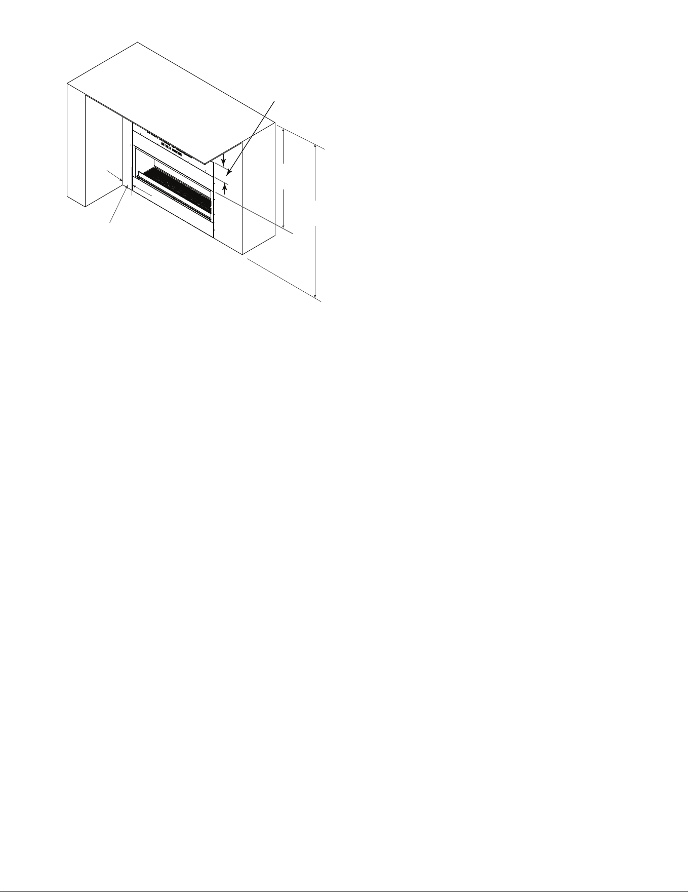
Ceiling or
Overhang
Additional
Structure or
Sidewall
12 in. or 8 in.
non-combustible
depending on
model.
39 in.
(990 mm)
min.
64 in.
(1626 mm)
min.
4 in.
(101 mm)
minimum - one side only.
Figure 3.5 Clearances to Combustibles

13
Outdoor Lifestyles by Hearth & Home Technologies • Lanai 48/60 Installation Manual • 4111-901 Rev. I • 06/23
F. Moisture Resistance
This outdoor appliance will shed moderate
amounts of water, but is not waterproof. This
appliance must be enclosed or covered with
noncombustible nish material and all joints
sealed to prevent water inltration.
The rebox will not perform as an exterior wall.
Moisture penetration must be considered for
construction that places the appliance in structure
walls or on moisture sensitive surfaces.
When installed on exterior walls: Hearth &
Home Technologies recommends that the chase
be constructed outside the structure’s weather
envelope. Where the platform meets the wall, use
a ashing detail similar to that required for attached
decks. Chase platforms, including hearths should
slope away from the structure at 1/8 in. to 1/4 in.
per foot. The appliance can be shimmed level.
Water Drainage: The Lanai is designed to operate
outdoors experiencing rain and other sources of
moisture that will enter the rebox. The appliance
has built-in drain holes in the base which will
allow moisture to pass through the bottom of the
enclosure. When constructing the enclosure, the
builder must provide a means of draining water
from under the appliance and out of the structure.
This can be achieved by properly positioned drain
holes, slots or other means to allow water to exit
at the lowest grade of the structure. Choosing
the location of the appliance is also important
so that an area that may experience excessive
water ow or standing water is avoided. In
some cases a drain pan is needed to ensure
proper drainage. This can be constructed from a
corrosion resistant metal, or suitable material for
outdoor use with a water resistant membrane.
A slope of 1/4” per foot toward the drain ports of
the structure is recommended. A drain pan can
also be purchased (ODLANAIG-48DP) for the 48
inch appliance or the (ODLANAIG-60DP) for the
60 inch appliance.
14
Outdoor Lifestyles by Hearth & Home Technologies • Lanai 48/60 Installation Manual • 4111-901 Rev. I • 06/23
A. Securing and Leveling Appliance
CAUTION! Risk of cuts, abrasions or ying
debris. Wear protective gloves and safety glasses
during installation. Sheet metal edges are sharp.
Position, level and secure the appliance.
• Install on wood, composite or non-combustible
continuous at surface, extending full width
and depth of the appliance to prevent damage.
• Level the appliance from side to side and front
to back.
• Shim the appliance with noncombustible
material, such as sheet metal, as necessary.
• Chase platforms, including hearths, should
slope away from the structure at 1/8 inch to
1/4 inch per foot.
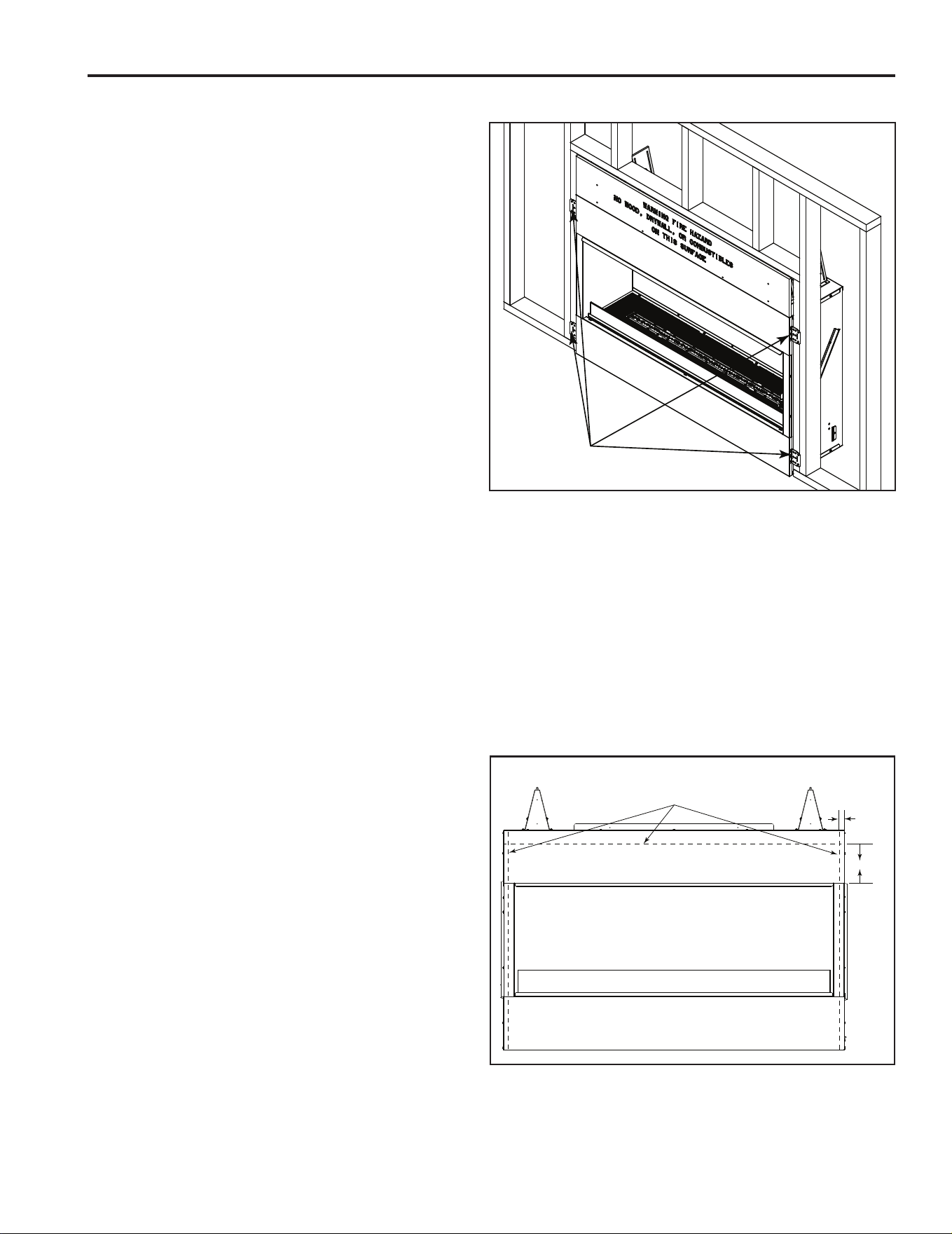
• Nailing tabs must be moved from shipping
position to installation position and secured
to framing. Bend the four nailing tabs out on
each side. See Figure 4.1.
B. Flashing
• Flash the appliance in a manner consistent with
regional practices to prevent water penetration
around the appliance. Due to elevated
temperatures across the top of the appliance,
metal ashing and high temperature sealant
must be used. Adhesive or polymer ashing
materials may melt.
• For brick, stone, stucco and similar
construction, weep screeds should be installed
per regional codes.
• See Section 3.F. and Figures 3.2 and 3.3 for
more information regarding wall and enclosure
construction required to prevent moisture
penetration into the structure. The appliance
will shed moderate amounts of water but is not
waterproof.
NOTE: Use high temp silicone or sealant
recommended by the manufacturer of the house
wrap to seal between combustible sheathing
house wrap and non-combustible sheathing. The
sealant material used within 6 inches of the top
and 1 inch on the sides of the appliance surround
must be approved to withstand a minimum
temperature of 225°F continuous exposure.
House wrap tape with a 225°F minimum
temperature may also be used. See Figure 4.2.
Nailing Flanges
(both sides)
4
Appliance Preparation
Figure 4.1. Positioning and Securing Nailing Flange
Figure 4.2. Membrane Overlap
1 in.
6 in.
Membrane Overlap
Dotted Lines
15
Outdoor Lifestyles by Hearth & Home Technologies • Lanai 48/60 Installation Manual • 4111-901 Rev. I • 06/23
A. Wiring Requirements
WARNING! Risk of Shock or Explosion! DO
NOT wire 110-120 Vac. to the valve or to the
appliance wall switch. Incorrect wiring will damage
controls.
NOTICE: This appliance must be electrically wired
and grounded in accordance with local codes,
or in the absence of local code, with National
Electric Code ANSI/NFPA 70-latest edition or
the Canadian Electric Code CSA C22.1.
Total Electrical Requirements: 110-120Vac.,
60Hz., less than 12 Amperes.
• Wire the appliance junction box to unswitched
110-120Vac. This is required for proper
operation of the appliance.
• A 110-120Vac. circuit for this appliance must be
protected with ground-fault circuit-interrupter
protection in compliance with the applicable
electrical codes.
• Low voltage and 110-120 VAC voltage cannot
be shared within the same wall box.
Electrical Service and Repair
WARNING! Risk of Shock! Label all wires prior
to disconnection when servicing controls. Wiring
errors could cause improper and dangerous
operation. Verify proper operation after servicing.
B. IntelliFire Pilot Ignition System
Wiring
• Wire the appliance junction box to 110-120Vac.
for proper operation of the appliance.
WARNING! Risk of Shock or Explosion! DO
NOT wire IPI controlled appliance junction box to
a switched circuit. Incorrect wiring will override IPI
safety lockout.
THIS APPLIANCE IS SUPPLIED STANDARD
WITH:
• IntelliFire control valve (3V)
• Wall switch Control – Operates appliance On/
Off and LED lights.
• Two (2) LED outdoor rated light strips (12V)
• Conductor wall switch wire
C. Installing the Electrical
The Lanai is supplied with the junction box located
on the right side of the appliance. There is no
option to relocate junction box to the left side of
the appliance.
Wiring Junction Box
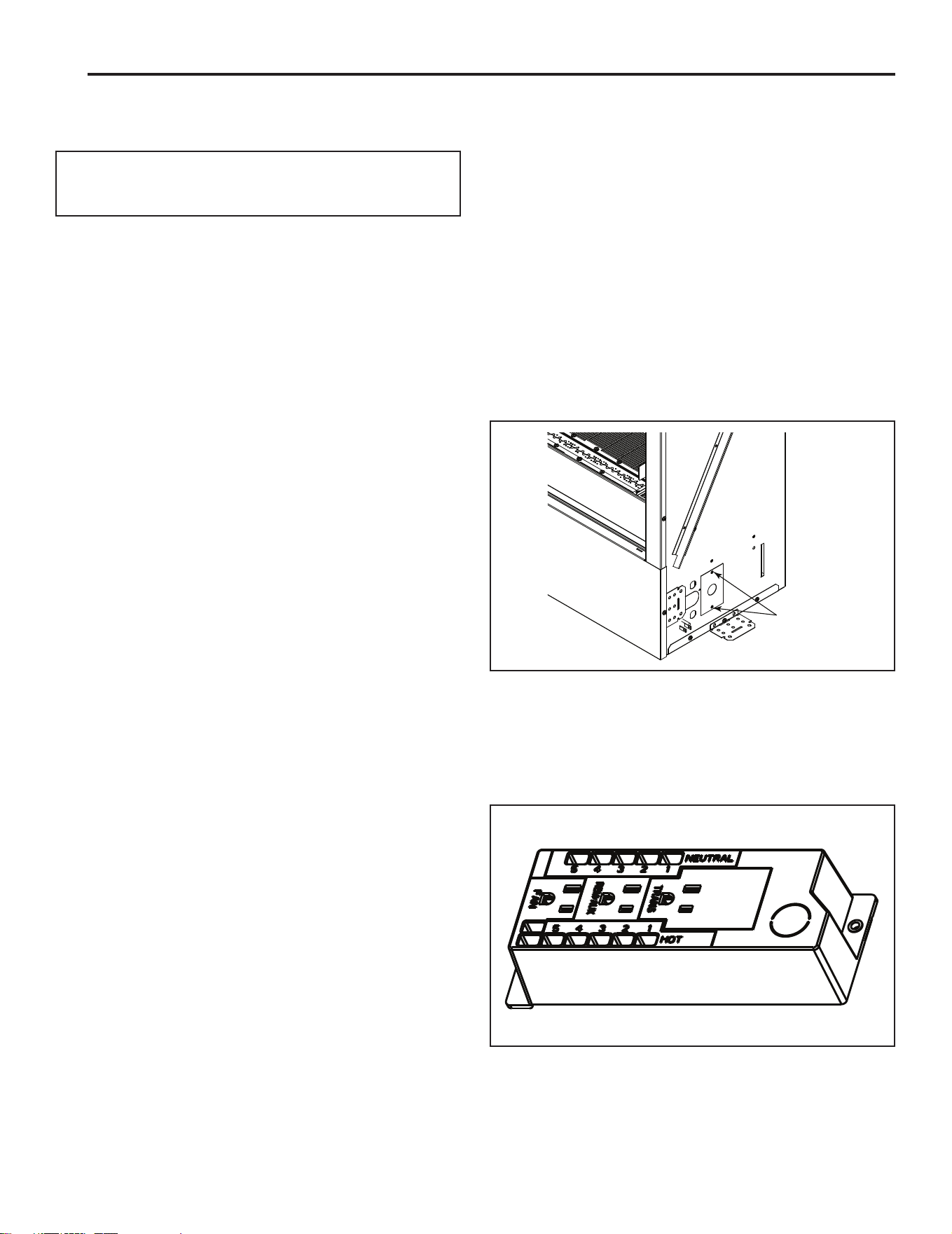
• Remove (2) screws securing junction box
access panel. See Figure 5.1.
• Unplug transformer and power supply.
• Disassemble junction box. See Figure 5.2
5
Electrical Information
Note: The Lanai appliance MUST be connected to a
GFCI (Ground Fault Circuit Interrupt) protected circuit
breaker.
Figure 5.1. Access Panel Removal
Figure 5.2. Junction Box
Screws
16
Outdoor Lifestyles by Hearth & Home Technologies • Lanai 48/60 Installation Manual • 4111-901 Rev. I • 06/23
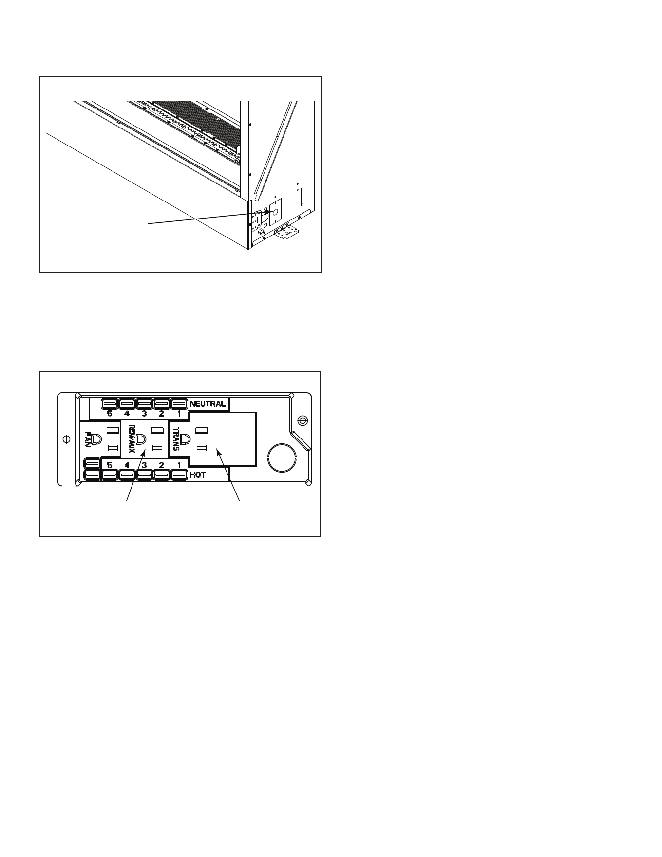
• Wire junction box and reassemble. See Figure
5.3.
• Plug in transformer and power supply to
junction box. See Figure 5.4.
Transformer
Power Supply
Black and white wires must
be wired inside box.
Figure 5.3. Wire Junction Box
Figure 5.4. Power Supply
17
Outdoor Lifestyles by Hearth & Home Technologies • Lanai 48/60 Installation Manual • 4111-901 Rev. I • 06/23
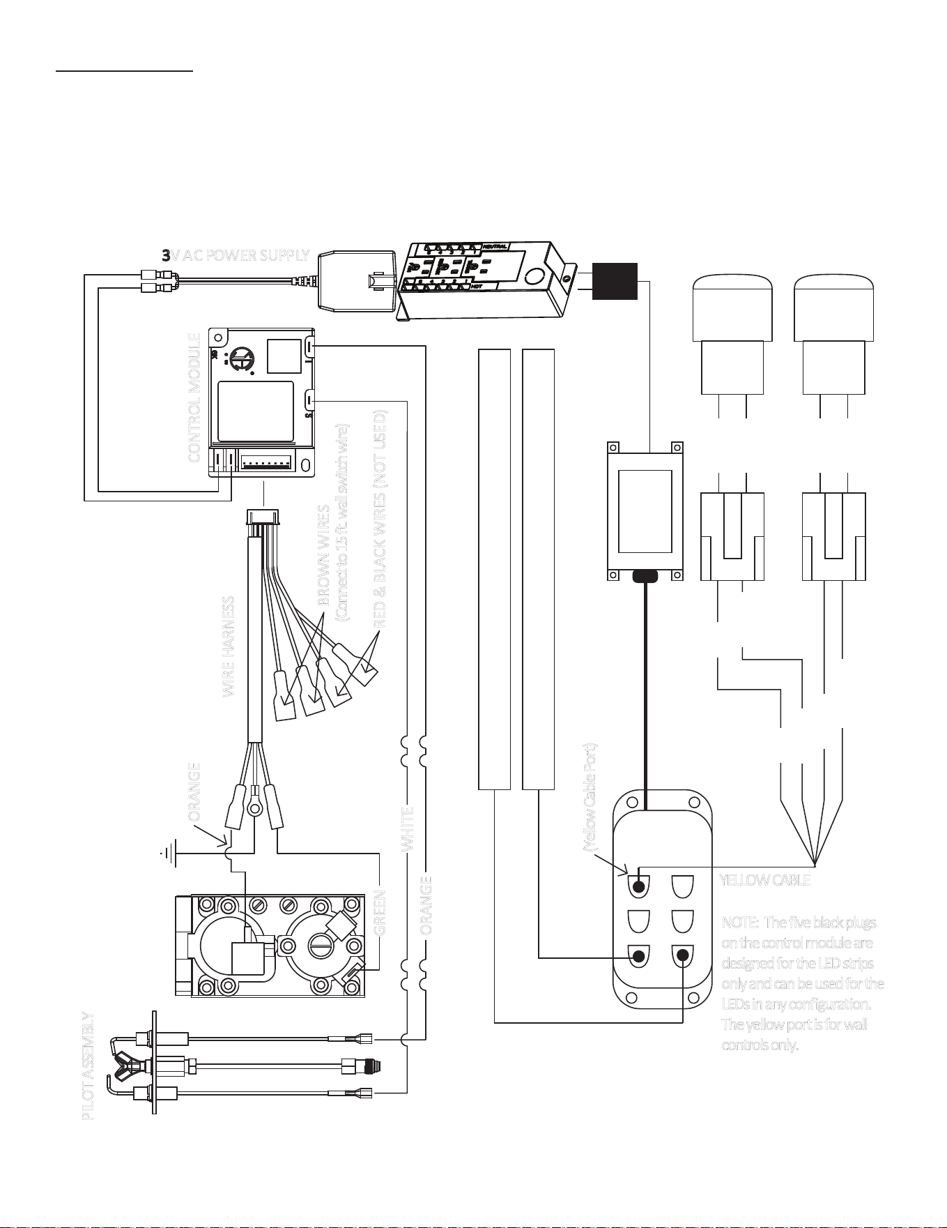
WIRE HARNESS
ORANGE
GREEN
GAS VALVE
CONTROL MODULE
V AC POWER SUPPLY
PILOT ASSEMBLY
O
RANGE
WHITE
BROWN WIRES
RED & BLACK WIRES (NOT USED)
LED STRIP
LED STRIP
TRANSFORMER
LED
CONTROL
MODULE
JUNCTION BOX
TOP BUTTON
ON/HI/MED/LO/OFF
BOTTOM BUTTON
Color Selection
3
RED
BLUE
YELLOW
GREEN
RED
BLACK
BLACK
BLACK
BLACK
GREEN
YELLOW CABLE
(Connect to 15 �. wall switch wire)
(Yellow Cable Port)
NOTE: The five black plugs
on the control module are
designed for the LED strips
only and can be used for the
LEDs in any configura�on.
The yellow port is for wall
controls only.
Wiring Diagram
Figure 5.5. Wiring Diagram
18
Outdoor Lifestyles by Hearth & Home Technologies • Lanai 48/60 Installation Manual • 4111-901 Rev. I • 06/23
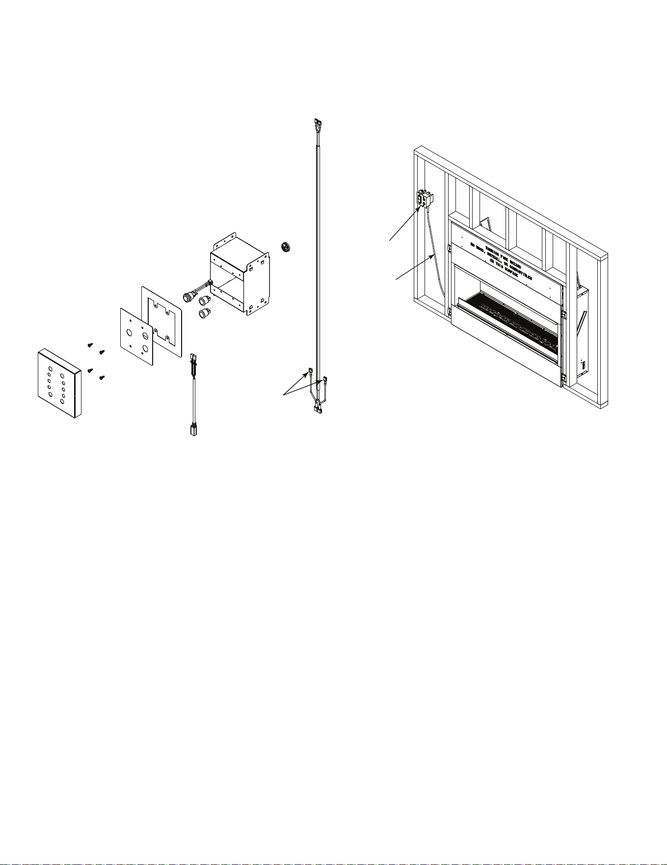
D. Wall Switch Control Assembly
The Lanai series outdoor gas appliance is
supplied with a wall switch control panel, and
control mounting box. See Figure 5.6.
NOTE: Supplied wire allows for the control
assembly to be mounted up to 14 feet from
the appliance. The supplied grommet can
be installed on the left or right side of the
appliance for wall switch control wire routing.
• The control box can be rerouted on the right or
left side of the appliance.
• Locate controls by lifting engine and using
support legs. To access Intellire control
module and LED control module, lift control
box cover off of controls.
• The rocker switch wire (Black/white) must
be plugged into the two brown wires on the
control wiring harness. There is no incorrect
connection for these two wires. Shown in
wiring diagram (Figure 5.5.)
• The yellow cable for the two LED buttons plugs
into the LED module (Yellow control module)
located under the control cover which is under
side of the engine base.
• Make sure the cable is completely engaged
and clip is over top of the plug.
• Using the tabs, mount the wall control switch
assembly to a stud within 14 feet of the
appliance.
Remote
Control
Terminals
Control
Mounting Box
Wall Switch
Wires
Figure 5.6. Wall Control Switch Assembly
Figure 5.7. Wall Switch Mounting
19
Outdoor Lifestyles by Hearth & Home Technologies • Lanai 48/60 Installation Manual • 4111-901 Rev. I • 06/23
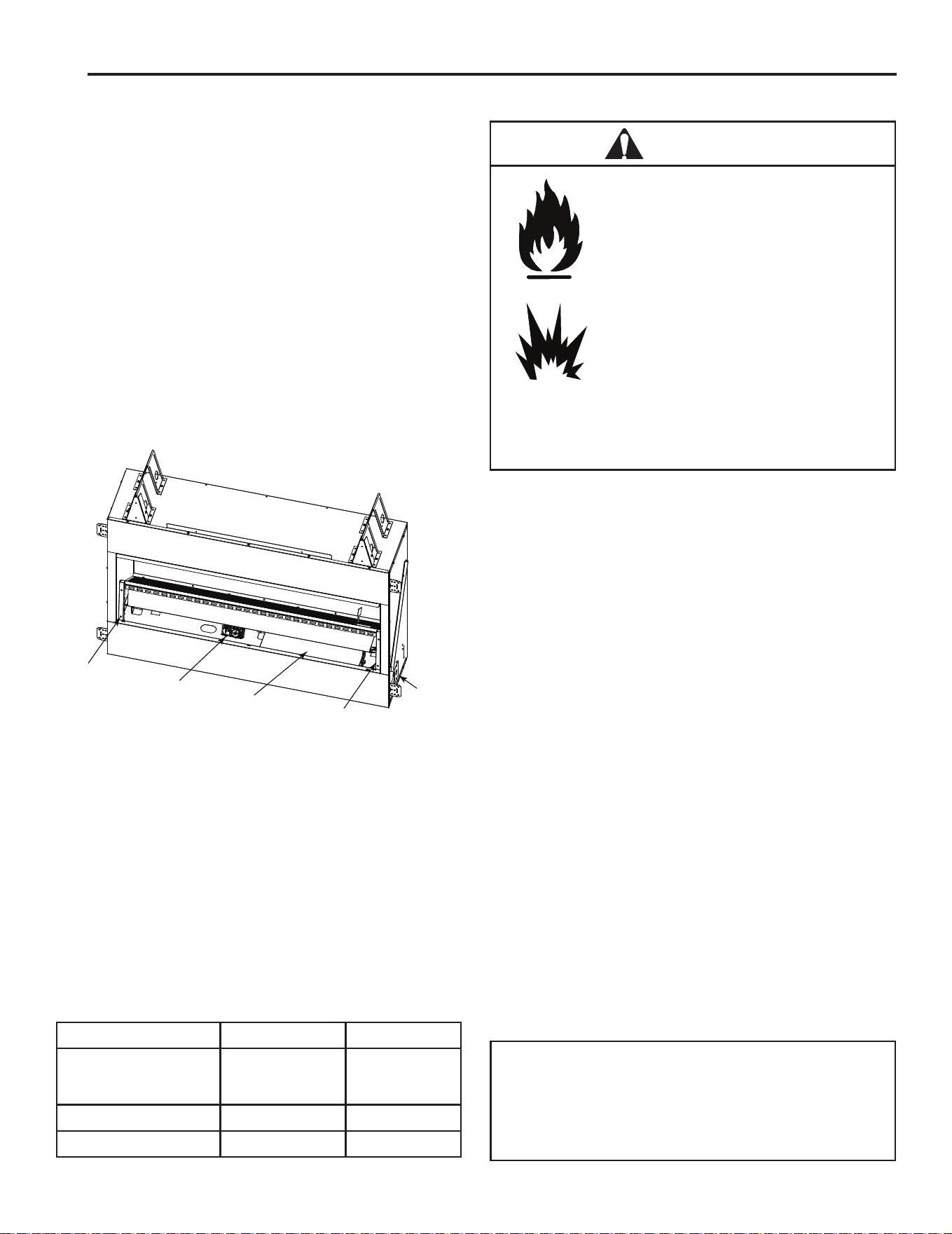
A. Valve Access
The valve and controls are located in the appliance
control box. See Figure 6.1.
The control box and controls can be accessed by
lifting engine assembly as shown in Figure 6.1
• Make sure appliance is off and cool.
• Remove media and deection glass panel
from hearth pan.
• Remove the 3 or 5 screws (depending on the
model) from the back of the hearth pan.
• Lift the front of the burner assembly and place
the two leg supports, provided under the Engine,
against lower front space at the bottom of the face,
and slide into the slots at the bottom of the engine
assembly. See Figure 6.1.
• Remove control box cover panel revealing
control board if access to any controls is
needed.
B. Gas Pressure
• Optimum appliance performance requires
proper input pressures.
• Gas line sizing requirements will be determined
in ANSI Z233.1 National Fuel Gas Code in the
USA and CAN/CGA B149 in Canada.
• Pressure requirements are:
These pressures can be veried by lifting engine
and removing control cover to reveal the valve.
When an appliance is connected to a xed piping
system, the installation must conform with local
codes,or in the absence of local codes with the
National Fuel Gas Code, ANSI Z223.1/NFPA 54
or International Fuel Gas Code.
Note: Have the gas supply line installed in
accordance with local codes, if any. If not, follow
ANSI Z223.1 Installation should be done by a
qualied installer approved and/or licensed as
required by the locality. (In the commonwealth of
Massachusetts, installation must be performed by
a licensed plumber or gas tter.)
6
Gas Information
Note: An individual manual shut-off valve
(not supplied) is required when installing this
appliance. The manual shut-off valve must be
located in an easily accessible area, no more
than six feet from the appliance.
WARNING
Fire Risk.
Explosion Hazard.
High pressure will damage valve. Low
pressure could cause an explosion.
• Disconnect gas supply piping BEFORE
pressure testing gas line at test
pressures above 1/2 psig.
• Close the manual shut-off valve
BEFORE pressure testing gas line at
test pressures equal to or less than 1/2
psig.
• Verify inlet pressures. Verify minimum pressures
when other household gas appliances are operating
• Install regulator upstream of valve if line pressure is
greater than 1/2 psig.
Gas Pressure Natural Gas Propane
Minimum inlet supply
for the purpose of input
adjustment
5.0 in. w.c. 11 in. w.c.
Maximum inlet pressure 10.5 in w.c. 13 in. w.c.
Manifold pressure 3.5 in. w.c. 10 in. w.c.
Leg Support
Bracket
Valve
Appliance
Control Box
Junction Box
Connection
Leg Support
Bracket
Figure 6.1. Appliance With Engine Lifted

20
Outdoor Lifestyles by Hearth & Home Technologies • Lanai 48/60 Installation Manual • 4111-901 Rev. I • 06/23
Note: A listed (and commonwealth of
Massachusetts approved) 1/2 inch (13mm)
T-handle manual shut-off valve and exible gas
connector are connected to the 1/2 inch (13mm)
control valve inlet.
• If substituting for these components,
please consult local codes for compliance.
C. Gas Connection
• Refer to Section 3 for location of gas line
access in appliance.
• The gap between supply piping and gas
access hole may be caulked with a minimum
of 300°F continuous exposure rating or stuffed
with noncombustible, unfaced insulation to
help prevent rodents and insects from getting
into the control area of the appliance.
• Ensure that gas line does not come in contact
with outer wrap of the appliance. Follow local
codes.
• Pipe incoming gas line into lower compartment.
• Connect incoming gas line to the 1/2 inch
(13mm) connection on the manual shut-off
valve.
WARNING! Risk of Fire or Explosion! Support
control when attaching pipe to prevent bending
gas line.
• A small amount of air will be in the gas supply
lines.
Light the appliance. It will take a short time for air
to purge from lines. When purging is complete,
the appliance will light and operate normally.
WARNING! Risk of Fire, Explosion or
Asphyxiation! Check all ttings and connections
with a non-corrosive commercially available leak-
check solution. DO NOT use open ame. Fittings
and connections could have loosened during
shipping and handling.
WARNING! Risk of Fire or Explosion! Gas
build-up during line purge could ignite.
• Purge should be performed by a qualied
service technician.
• Ensure adequate ventilation.
• Ensure there are no ignition sources such as
sparks or open ames.
D. Fuel Conversion
• Make sure the appliance is compatible with
available gas types.
• The Lanai series gas appliance is supplied
from the factory for use with natural gas. If a
Propane(LP) conversion is required, kit LPK-
ODLANAIG48 or LPK-ODLANAIG60 must be
purchased in order to convert the appliance
for use with propane.
• Conversions must be made by a qualied
service technician using Hearth & Home
Technologies specied and approved parts.
E. High Altitude Installations
Notice: If the heating value of the gas has been
reduced, these rules do not apply. Check with your
local gas utility or authorities having jurisdiction.
When installing above 2000 feet elevation:
• In the USA: Reduce input rate 4% for each
1000 feet above 2000 feet.
• In Canada: Input ratings are certied without a
reduction of input rate for elevations up to 4500
feet (1370m) above sea level. Please consult
provincial and/or local authorities having
jurisdiction for installations at elevations above
4500 feet (1370m.)
Check with your local gas utility to determine
proper orice size. See conversion kit (LPK-
ODLANAIG48 or LPK-ODLANAIG60) for
instructions on how to change main burner orice.
21
Outdoor Lifestyles by Hearth & Home Technologies • Lanai 48/60 Installation Manual • 4111-901 Rev. I • 06/23
7
Finishing
A. Facing Material
The appliance structure can be covered with any
noncombustible material. Refer to Section 1.D.
WARNING! Risk of Fire! DO NOT apply
combustible materials beyond the minimum
clearances. Comply with all minimum clearances
to combustibles as specied in this manual.
Overlapping materials could ignite. Any
installation outside the scope as stated in this
manual please contact your authorized Hearth &
Home Technologies dealer prior to installation.
Mantel and Wall Projections
WARNING! Risk of Fire! Comply with all minimum
clearances to combustible as specied. Framing or
nishing material closer than the minimums listed
must be constructed entirely of noncombustible
materials (i.e. steel studs, concrete board, etc.)
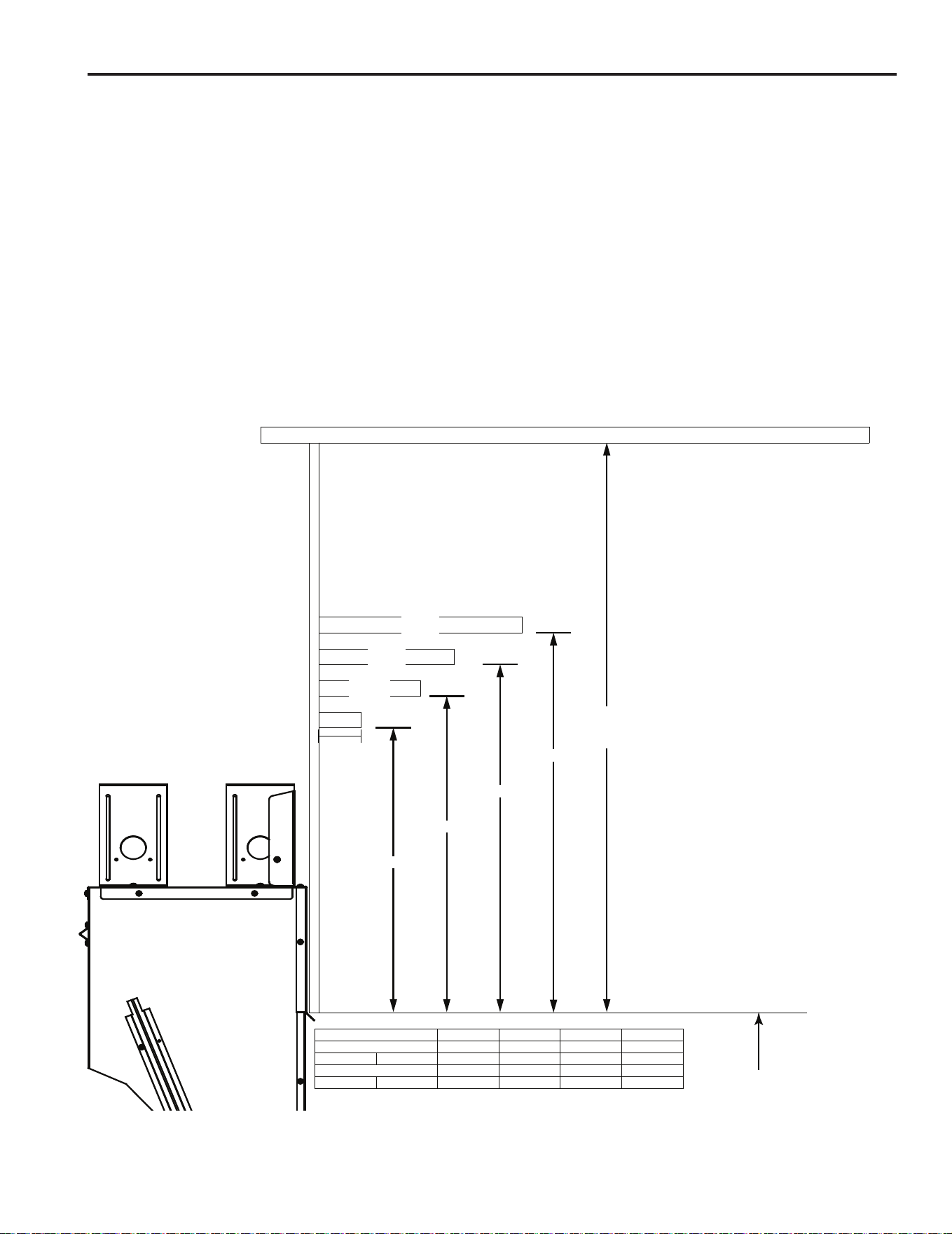
Figures 7.1 and 7.2 show the dimensions for
mantels or other combustible projections above
the appliance opening.
Firebox Opening
A
B
C
D
39 in. (990mm)
minimum to
ceiling
12in.
305mm
2½in
63½mm
6in.
152mm
8in.
203mm
A
B
C
D
COMBUSTIBLE
18 IN
20 IN
22 IN
24 IN
457 mm
508 mm
559 mm
610 mm
NON-COMBUSTIBLE
0 IN
2 IN
4 IN
6 IN
0 mm
51 mm
102 mm
152 mm
Figure 7.1. Minimum vertical and maximum horizontal mantel dimensions for combustible and non-combustible materials.
22
Outdoor Lifestyles by Hearth & Home Technologies • Lanai 48/60 Installation Manual • 4111-901 Rev. I • 06/23
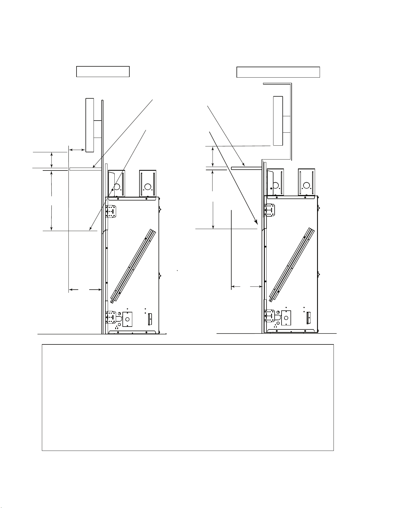
Good Faith Guidelines for TV Installa�ons above a Typical Gas Fireplace
Notes:
1. TV installation as shown requires the mantel be constructed entirely of non-combustible material
as it is below the allowable height for a combustible mantel.
2. These are good faith recommended clearances only and not a guarantee of compliance with all TV
manufacturers’ maximum allowable operating temperatures.
3. Since every home has unique air ow characteristics and maximum allowable operating temperatures
can vary from manufacturer to manufacturer and from model to model, actual TV temperatures should be
validated at the time of each installation. TVs should not be used in situations where the actual TV
temperature exceeds the manufacturers’ maximum allowable operating temperatures identied in the
TV’s technical specications. Contact the TV’s manufacturer directly if you cannot locate this information
or have questions regarding the information.
4. Mantel height and depth must conform to mantel requirements specied in the appliance installation
manual.
TV on the wall
TV recessed into the wall
TV
TV
6” Min.
12”
Min.
14”Min.
6” Min.
14” Min.
12”
Min.
Measured from top
of rebox opening.
Noncombustible
Mantel (required)
6” Min.
Figure 7.2. Good Faith TV Guidelines
23
Outdoor Lifestyles by Hearth & Home Technologies • Lanai 48/60 Installation Manual • 4111-901 Rev. I • 06/23
A. Remove the Shipping Materials
Remove the plastic coating and shipping materials
from the rebox.
WARNING! Risk of Fire! Close the ball valve
before installing the media template to prevent
accidental lighting. Remove the media template
before lighting the appliance.
B. Clean the Appliance
Clean/vacuum any sawdust that may have
accumulated inside the rebox.
C. Optional Accessories
Install approved accessories per instructions
included with accessories. Contact your dealer for
a list of approved accessories.
WARNING! Risk of Fire and Electric Shock! Use
ONLY Hearth & Home Technologies-approved
optional accessories with this appliance. Using
non-listed accessories could result in a safety
hazard and will void the warranty.
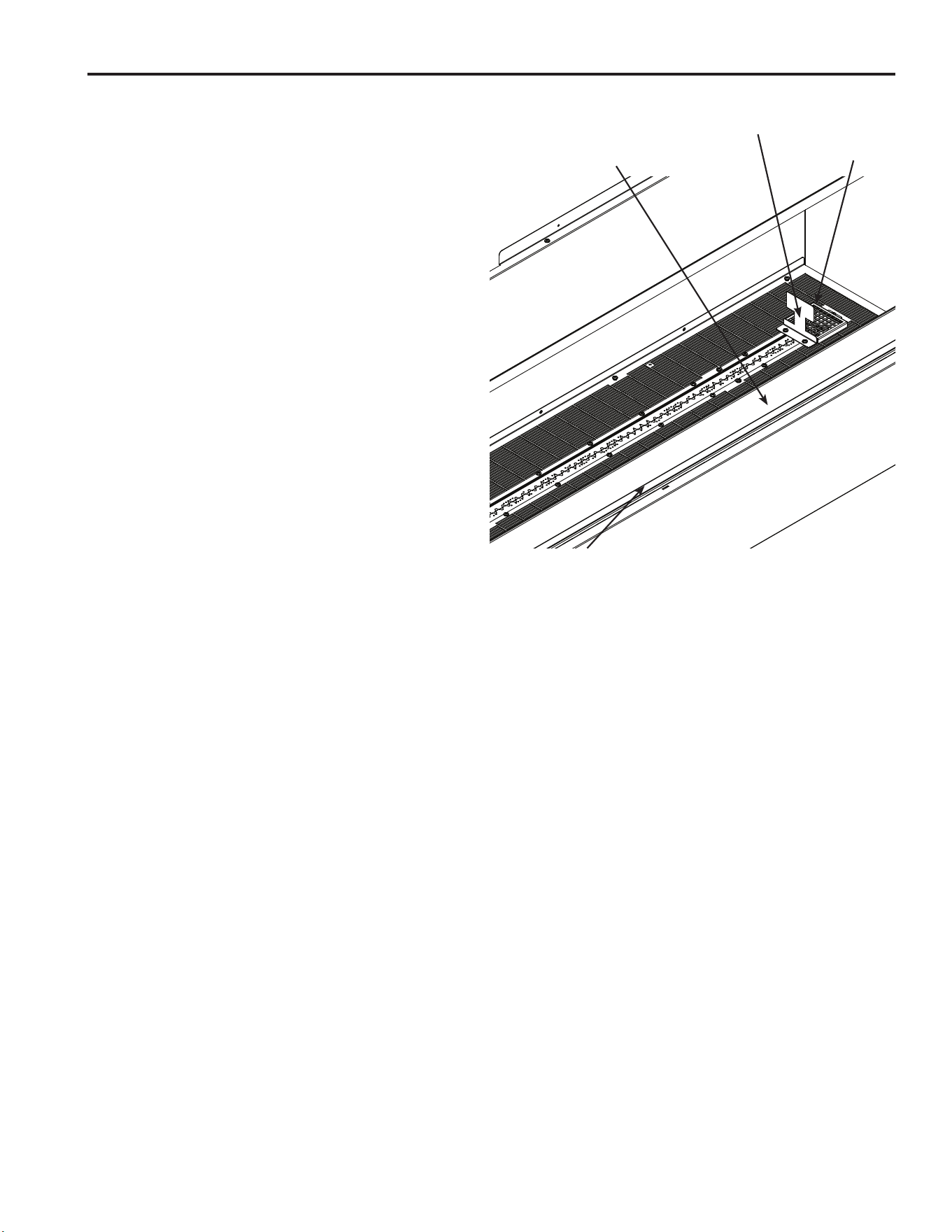
D. Verify Pilot Shield
Ensure proper placement of the pilot shield and
media placement template. See Figure 8.1.
Shipping could cause then to become displaced.
E. Install Deection Glass
Deection glass is stored on top of the media tray.
Remove the two brackets holding the deection
glass. Remove deection glass packaging.
Carefully place deection glass into support
bracket provided. See Figure 8.1.
F. Install Clear Crystal Media
Pour crystal media into the hearth area. Cover the
entire hearth pan area evenly, including burner
area and the pilot cover.
G. Remove Media Placement Template
Remove screws attaching the media placement
template and remove. Do not discard template.
This must be used at any time media is applied to
appliance.
8
Appliance setup
Figure 8.1. Media Placement Template
Media placement
Template
Deection Glass
Glass Support Bracket
Pilot Shield

24
Outdoor Lifestyles by Hearth & Home Technologies • Lanai 48/60 Installation Manual • 4111-901 Rev. I • 06/23
9
Reference Materials
A. Accessories
LP Conversion Kit:
• LPK-ODLANAIG48
• LPK-ODLANAIG60
Media Kits: NOTE: Same media kit for ODLANAIG-48 and ODLANAIG-60
• Media-Ebony-48
• Media-Cobalt-48
• Media-Red-48
• Media-Amber-48
Optional Screen – ODLANAIG-48SCN/ODLANAIG-60SCN
• The Lanai series outdoor gas appliance offers a protection screen that is designed
to protect the inside of the appliance from trash and other debris (sticks, leaves,
etc.) while not in use. This appliance may be operated with the screen installed.
Optional Trim Kit – ODLANAIG-48CFT/ODLANAIG-60CFT
• The Lanai series outdoor gas appliance offers a trim kit that will allow the owner
the option to cover the face of the appliance down to the rebox opening. This
four (4) piece kit comes with an integrated eyebrow and 3/4” stainless steel lip that
frames in the opening for a clean and seamless install.
Optional Drain Pan – ODLANAIG-48DP/ODLANAIG-60DP
• The Lanai series outdoor gas appliance offers a drain pan that is designed to
channel moisture to the front or rear of the enclosure housing the appliance. This
option will help ensure moisture does not become trapped inside the structure
and helps to keep the area under the appliance free of standing water.
Optional Contemporary Driftwood Log Set - CDLS
Optional Stone Kit - STONEKIT
NOTE: CDLS and STONEKIT cannot be used in conjunction with each other.
25
Outdoor Lifestyles by Hearth & Home Technologies • Lanai 48/60 Installation Manual • 4111-901 Rev. I • 06/23
B. Addendum
16’
20’
12’
20’
1. Add lengths of the outside
living space.
16’+20’+16’+20’=72’
2. Divide the open area length
by the total outdoor living
space.
20/72=.28
.28 is less than the .30 required
and therefore this installation
would not be approved.
1. Add lengths of the outside
living space.
12’+20’+12’+20’=64’
2. Divide the open area length
by the total outdoor living
space.
20/64=.31
.31 is greater than the .30
required and therefore this
installation would be approved.
How to Calculate the Minimum Opening Needed In an Outdoor Living Space
30% (or .30) of the outdoor living
space periphery needs to be
open.

26
Outdoor Lifestyles by Hearth & Home Technologies • Lanai 48/60 Installation Manual • 4111-901 Rev. I • 06/23
Outdoor Lifestyles, a brand of Hearth & Home Technologies
2571 215th Street West, Lakeville, MN 55044
www.hearthnhome.com
Please contact your Outdoor Lifestyles dealer with any questions or concerns.
For the location of your nearest Outdoor Lifestyles dealer,
please visit www.hearthnhome.com