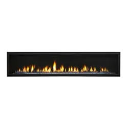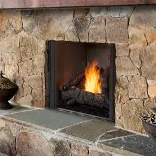
Installation Manual
Installation and Setup
INSTALLER: Leave this manual with party responsible for use and operation.
OWNER: Retain this manual for future reference.
Model(s):
NOTICE: DO NOT discard this manual!
• DO NOT store or use gasoline or other
ammable vapors and liquids in the vicinity
of this or any other appliance.
•
DO NOT overre. Overring will void your
warranty.
• Comply with all minimum clearances to
combustibles as specied. Failure to com-
ply may cause house re.
WARNING: If the information in these
instructions is not followed exactly, a re
or explosion may result causing property
damage, personal injury, or death.
Carefully review the instructions supplied
with the decorative type unvented room
heater for the minimum fireplace size
requirement.
DO NOT INSTALL AN APPLIANCE IN THIS
FIREBOX UNLESS THIS FIREBOX MEETS
THE MINIMUM DIMENSIONS REQUIRED
FOR THE INSTALLATION.
HOT SURFACES!
Firebox surfaces are hot during
operation AND cool down.
Hot surfaces will cause burns.
• DO NOT touch rebox until it is cooled
• NEVER allow children to touch rebox
• Keep children away
• CAREFULLY SUPERVISE children in same room as rebox.
• Alert children and adults to hazards of high temperatures.
High temperatures may ignite clothing or other ammable
materials.
• Keep clothing, furniture, draperies and other ammable
materials away.
DANGER
FOR USE ONLY WITH A LISTED GAS-FIRED UNVENTED DECO-
RATIVE ROOM HEATER NOT TO EXCEED 40,000 BTU/H.
DO NOT BUILD A WOOD FIRE.
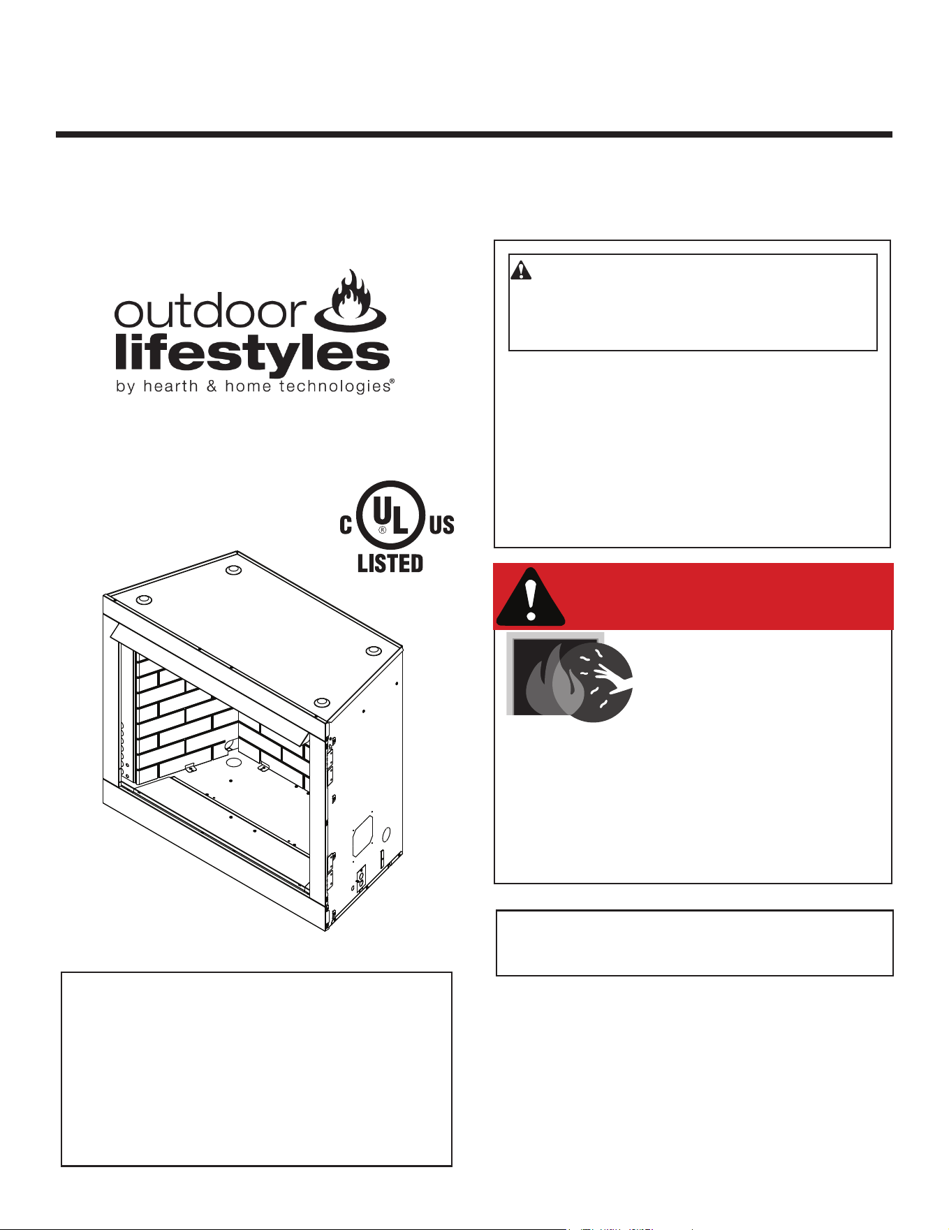
VOFB36-T, VOFB36-H,
VOFB42-T, VOFB42-H
MH62953
GAS-FIRED
1
Outdoor Lifestyles • VOFB36/42 Installation Manual • 4153-901 • Rev B • 04/23

Safety Alert Key:
• DANGER! Indicates a hazardous situation which, if not avoided will result in death or serious injury.
• WARNING! Indicates a hazardous situation which, if not avoided could result in death or serious injury.
• CAUTION! Indicates a hazardous situation which, if not avoided, could result in minor or moderate injury.
• NOTICE: Indicates practices which may cause damage to the replace or to property.
Table of Contents
Installation Standard Work Checklist 3
1 Product Specic Information
A. Firebox Certication 4
B. BTU Specications 4
C. High Altitude Installations 4
D. Non-Combustible Materials Specication 4
E. Combustible Materials Specication 4
F. Electrical Codes 4
2 Getting Started
A. Design and Installation Considerations 5
B. Tools and Supplies Needed 5
C. Inspect Firebox and Components 5
D. Appliance Location Requirments for Outdoor Space 6
3 Firebox Dimensions
A. Firebox Dimensions/Weights 7
B. Hearth Dimensions 8
C. Framing Dimensions 9
D. Clearance to Combustibles 10
E. Constructing the Appliance Chase 11
4 Firebox Preparation
A. Securing and Leveling the Firebox 12
B. Moisture Resistance 12
5 Electrical Information
A. Wiring Requirements 14
B. Wiring the Junction Box 14
C. Electrical Service and Repair 14
6 Gas Information
A. Fuel Type 15
B. Gas Pressure 15
C. Gas Connection 15
7 Finishing
A. Facing Material 16
B. Mantel and Wall Projections 16
C. Decorative Fronts 17
D. TV Good Faith Guidelines 18
8 Firebox Setup
A. Remove the Shipping Materials 19
B. Clean the Firebox 19
C. Hood Installation 19
D. Adjustable Firebox Supports 19
9 Reference Materials
A. Optional Accessories 21
B. Contact Information 22
2
Outdoor Lifestyles • VOFB36/42 Installation Manual • 4153-901 • Rev B • 04/23
►
►
►
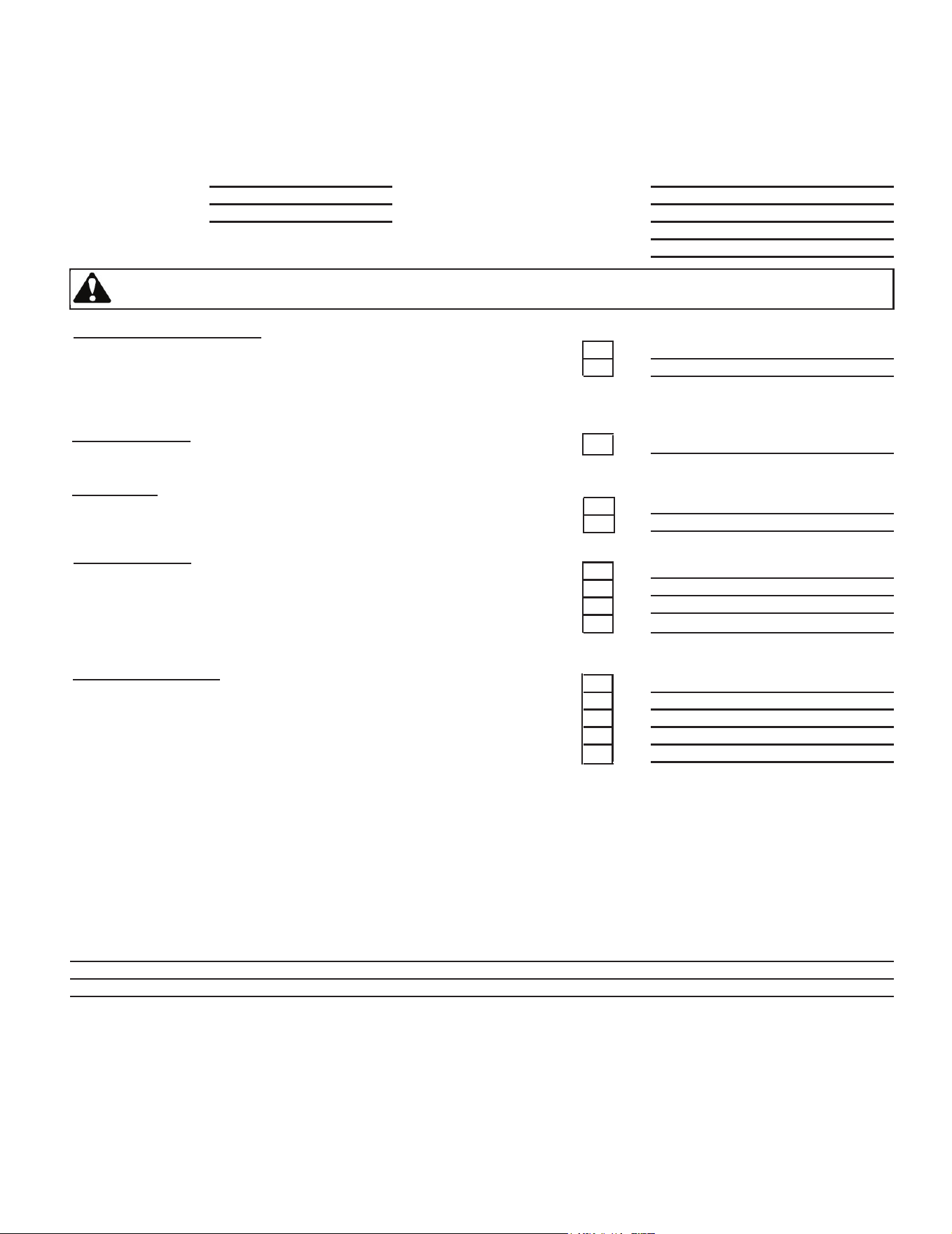
Customer:
Lot/Address
Model (circle one):
VOFB36-T, VOFB36-H
VOFB42-T, VOFB42-H
YES IF NO, WHY?
ATTENTION INSTALLER:
Follow this Standard Work Checklist
This standard work checklist is to be used by the installer in conjuction with, not instead of, the instructions contained in this installation
manual.
Date Installed:
Location of Firebox:
Installer:
Dealer/Distributor Phone #
Serial #:
WARNING! Risk of Fire or Explosion! Failure to install firebox acording to these instructions can lead to a fire or
explosion.
Comments communicated to party responsible
4153-982 • Rev A • 1/22
• Photographing the installation and copying this checklist for your file.
(Builder/Gen. Contractor) (Installer) (Date)
Comments: Further description of the issues, who is responsible (Installer/Builder/Other Trades, etc.) and corrective action needed:
• That this checklist remain visible at all times on the fireplace until the installation is complete.
__________________________ by ______________________on _________
Firebox Install Section(s) 3 & 4
Verified clearances to combustibles.
Firebox is leveled and secured.
Electrical Section 5
Unswitched power (110-120 VAC) provided to the firebox.
Gas Section 6
Proper fuel type
Leak check performed and inlet pressure verified.
Finishing Section 7
Combustible materials not installed in non-combustible areas.
Verified all clearances meet installation manual requirements.
Mantels and wall projections comply with installation manual requirements.
Hearth extension installed per manual requirements.
Firebox Setup Section 8
All packaging and protective materials removed.
Refractory installed correctly.
Firescreen installed properly.
Manual bag and all of its contents are removed from the firebox and given to
the party responsible for use and operation.
Hearth & Home Technologies recommends the following:
3
Outdoor Lifestyles • VOFB36/42 Installation Manual • 4153-901 • Rev B • 04/23
A. Firebox Certication
NOT INTENDED FOR USE AS A PRIMARY HEAT SOURCE.
This appliance is tested and approved as either supplemen-
tal room heat or as a decorative appliance. It should not be
factored as primary heat in residential heating calculations.
NOTICE: This installation must conform with local codes.
In the absence of local codes you must comply with the
National Fuel Gas Code, ANSI Z223.1/NFPA 54.
This product is listed to ANSI standards for “Ventless Gas
Firebox Enclosures for Gas-Fired Unvented Gas Log
Type Room Heaters".
MODELS: VOFB36-T, VOFB36-H
VOFB42-T, VOFB42-H
LABORATORY: Underwriters Laboratories, Inc. (UL)
TYPE: Ventless Firebox Enclosures for Gas-Fired
Unvented Gas Log Type Room Heaters
STANDARD: CSA/ANSI-Z21.91:20
Indoor Use: The installed gas appliance must be listed
in accordance with CSA/ANSI Z21.11.2:19 Gas fired
unvented room heaters not to exceed 40,000 BTU/hr
(11723 W)
Outdoor use: The installed gas appliance must be listed
in accordance with CSA/ANSI Z21.97-2017 Outdoor
decorative appliance and CSA/ANSI Z21.11.2:19 Unvented
room heater not to exceed 40,000 BTU/hr (11,723 W)
B. BTU Specications
WARNING: This product and the
fuels used to operate this product (liquid
propane or natural gas), and the products
of combustion of such fuels, can expose
you to chemicals including benzene, which
is known to the State of California to cause
cancer and reproductive harm. For more
information go to: www.P65Warnings.
ca.gov.
1 1
Product Specic Information
Model(s) Altitude Maximum
Allowable
BTU/hr
VOFB36-T/H (0-2000 FT) 40,000
VOFB42-T/H (0-2000 FT) 40,000
D. Non-Combustible Materials Specication
Material which will not ignite and burn. Such materials are
those consisting entirely of steel, iron, brick, tile, concrete,
slate, glass or plasters, or any combination thereof.
Materials that are reported as passing ASTM E 136,
Standard Test Method for Behavior of Materials in
a Vertical Tube Furnace at 750 ºC shall be considered
non-combustible materials.
E. Combustible Materials Specication
Materials made of or surfaced with wood, compressed pa-
per, plant bers, plastics, or other material that can ignite
and burn, whether ame proofed or not, or plastered or
unplastered shall be considered combustible materials.
F. Electrical Codes
NOTICE: This appliance must be electrically wired
and grounded in accordance with local codes or, in the
absence of local codes, with National Electric Code
ANSI/NFPA 70-latest edition.
C. High Altitude Installations
NOTICE: If the heating value of the gas has been reduced,
these rules do not apply. Check with your local gas utility
or authorities having jurisdiction.
When installing above 2000 feet elevation:
• In the USA: Reduce input rate 4% for each 1000 feet
above 2000 feet.
Check with your local gas utility to determine proper
orice size.
Note: Smoke, carbon monoxide or combination alarms
Alarm manufacturers recommend that alarms be kept at
least 15 ft. to 20 ft. laterally away from fuel-burning sources.
Installing the alarm closer than 15 ft. will not harm the
alarm, but may increase the frequency of nuisance alarms.
Mounting alarms on the wall versus the ceiling will further
reduce nuisance alarms.
4
Outdoor Lifestyles • VOFB36/42 Installation Manual • 4153-901 • Rev B • 04/23

A. Design and Installation Considerations
Installation MUST comply with local, regional, state and
national codes and regulations. Consult insurance carrier,
local building inspector, re ocials or authorities having
jurisdiction over restrictions, installation inspection and
permits.
Before installing, determine the following:
• Where the rebox is to be installed.
• Gas supply piping requirements.
• Electrical wiring requirements.
• Framing and nishing details.
• Whether optional accessories - are desired.
C. Inspect Firebox and Components
• Carefully remove the rebox and components from the
packaging.
• Report to your dealer any parts damaged in shipment.
• Read all of the instructions before starting the instal-
lation. Follow these instructions carefully during the
installation to ensure maximum safety and benet.
WARNING! Risk of Fire or Explosion! Damaged parts
could impair safe operation. DO NOT install damaged,
incomplete or substitute components. Keep rebox dry.
B. Tools and Supplies Needed
Before beginning the installation be sure that the following
tools and building supplies are available.
Tape measure Framing material
Pliers Hammer
Phillips screwdriver Level
Gloves Framing square
Electric drill and bits
Safety glasses
Reciprocating saw
Caulking material (300ºF minimum continuous exposure
rating)
Note: Refer to the installation instructions provided with
the log set for items required for log set installation.
Hearth & Home Technologies disclaims any responsibility
for, and the warranty will be voided by, the following actions:
• Installation and use of any damaged rebox or system
component.
• Modication of the rebox.
• Installation other than as instructed by Hearth & Home
Technologies.
• Improper positioning of the gas logs.
• Installation and/or use of any component part not approved
by Hearth & Home Technologies.
Any such action may cause a re hazard.
WARNING! Risk of Fire, Explosion or Electric Shock!
DO NOT use this rebox if any part has been under water.
Call a qualied service technician to inspect the rebox
and to replace any part of the control system and/or gas
control which has been under water.
Improper installation, adjustment, alteration, service or
maintenance can cause injury or property damage. For
assistance or additional information, consult a qualied
service technician, service agency or your dealer.
Installation and service of this appliance should be performed by
qualied personnel. Hearth & Home Technologies recommends
HHT Factory Trained or NFI certied professionals.
2 2
Getting Started
The Vesper series gas appliance is designed for outdoor
use and may be installed as a stand alone unit or built into
a wall. Install on wood, composite or non-combustible at
surface, extending full width and depth of the appliance to
prevent damage.
Outdoor spaces - For the purpose of these instructions,
an appliance is considered to be outdoors if installed with
shelter no more inclusive than:
1. With walls on all sides, but no overhead cover
2. Within a partial enclosure which includes an overhead
cover and no more than two side walls. These side walls
may be parallel, as in a breezeway, or at right angles to
each other; or
3. Within a partial enclosure which includes an overhead
cover and three sidewalls, as long as 30 % or more of the
horizontal periphery of the enclosure is permanently open.
NOTE: Screen may be used on the open sides of the shel-
ter. 14x18 and 16x18 screen mesh is approved for use. DO
NOT use solar screen or no-see-um screen.
If appliance does not meet the above requirements, it must
have a Z21.11.2 unvented heater installed.
NOTE: See page 6 for additional information on appliance
locations requirements for outdoor living spaces.
5
Outdoor Lifestyles • VOFB36/42 Installation Manual • 4153-901 • Rev B • 04/23
►
16’
20’
12’
20’
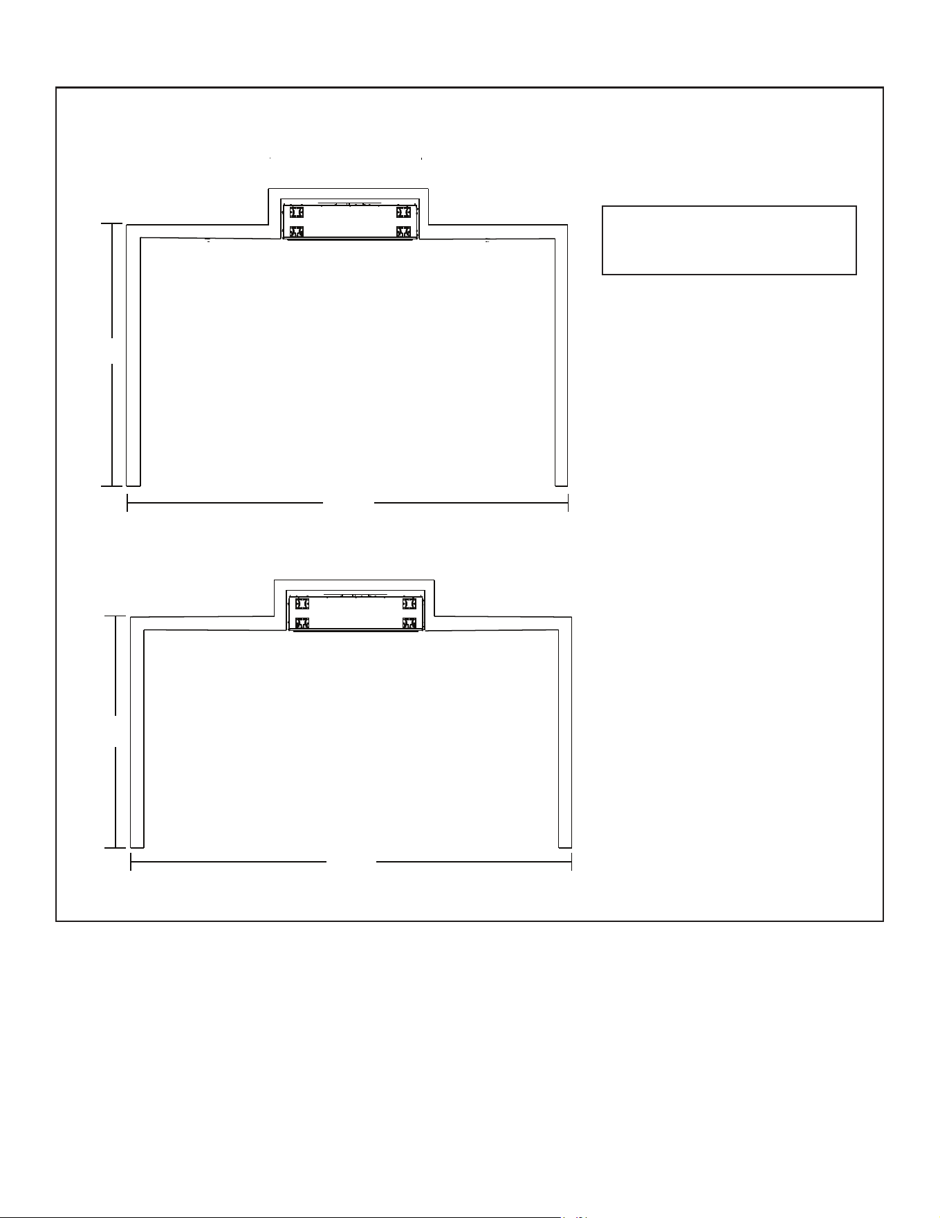
1. Add lengths of the outside
living space.
16’+20’+16’+20’=72’
2. Divide the open area length
by the total outdoor living
space.
20/72=.28
.28 is less than the .30 required
and therefore this installation
would not be approved.
1. Add lengths of the outside
living space.
12’+20’+12’+20’=64’
2. Divide the open area length
by the total outdoor living
space.
20/64=.31
.31 is greater than the .30
required and therefore this
installation would be approved.
How to Calculate the Minimum Opening Needed In an Outdoor Living Space
30% (or .30) of the outdoor living
space periphery needs to be
open.
D. Appliance Location Requirements in Outdoor Living Space
Figure 2.1 Outdoor Living Space
6
Outdoor Lifestyles • VOFB36/42 Installation Manual • 4153-901 • Rev B • 04/23
3 3
Firebox, Hearth, Framing Dimensions and Clearances
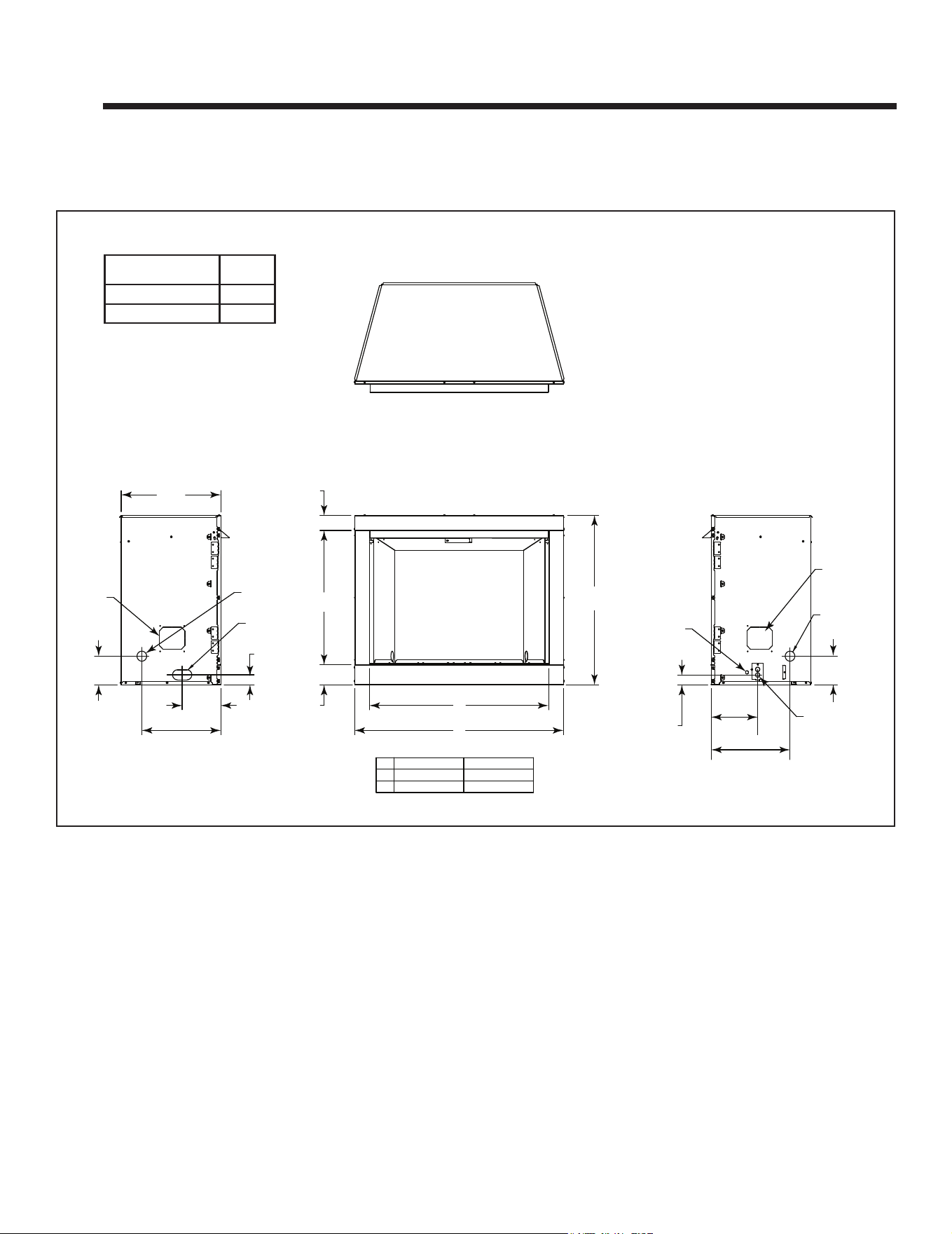
A. Firebox Dimensions/Weights
Dimensions are actual rebox dimensions. Use for reference only. For framing dimensions and clearances refer to page 8.
Figure 3.1 Firebox Dimensions
B
4 in
(102 mm)
27 in
(686 mm)
3 in
(76 mm)
34 in
(864 mm)
A
20 in
(508 mm)
15-7/8 in
(403 mm)
5-3/4 in
(146 mm)
5-3/4 in
(146 mm)
15-7/8 in
(403 mm)
2 in
(51 mm)
7-3/4 in
(197 mm)
2 in
(50 mm)
9-3/8 in
(238 mm)
36" 42"
A 36 in (914 mm) 42 in (1067 mm)
B 42 in (1067 mm) 48 in (1219 mm)
Gas Access
Above Hearth
Outside Air
Electrical Access
Wall Switch
Strain Relief
Outside
Air
Gas Access
Above Hearth
Gas Access
Below Hearth
Model Pounds
VOFB36-T/H 140
VOFB42-T/H 155
Firebox Weights
7
Outdoor Lifestyles • VOFB36/42 Installation Manual • 4153-901 • Rev B • 04/23
A
B
C
D
E
FP2901
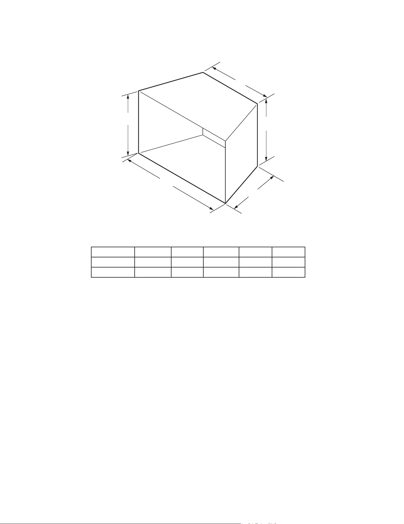
hearth dims
Figure 3.2 Minimum Hearth Dimensions
B. Hearth Dimensions
.
Model A B C D E
VOFB36 32-7/8 in. 15 in. 24-3/8 in. 25-1/2 in. 22-5/8 in.
VOFB42 38-7/8 in. 15 in. 30-3/8 in. 25-1/2 in. 22-5/8 in.
8
Outdoor Lifestyles • VOFB36/42 Installation Manual • 4153-901 • Rev B • 04/23
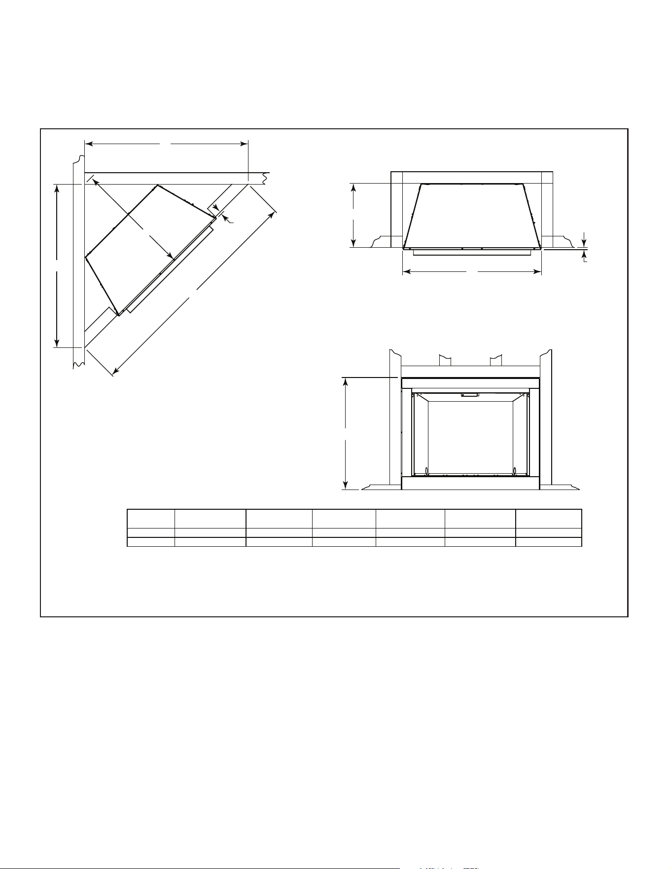
C. Framing Dimensions
WARNING! Risk of Fire or Burns! Provide adequate
clearance around air openings and for service access.
Due to high temperatures, the appliance should be lo-
cated out of trac and away from furniture and draperies.
NOTICE: Illustrations reect typical installations and are
FOR DESIGN PURPOSES ONLY. Illustrations/diagrams
are not drawn to scale. Actual installation may vary due to
individual design preference.
Figure 3.3 Framing Dimensions
A
5/8 in
B
F
E
D
D
5/8 in
C
Note: Add 1/2 inch to width (A) and 1/4 inch to
height (B) dimensions when using optional trim
kit to nish the installation of a custom cabinet,
mantle, or other built-in enclosure.
MODEL A B C D E F
VOFB36 42-1/2 in 50 in 70-3/4 in 36 in
VOFB42 48-1/2 in 54-1/4 in 76-3/4 in 38-1/2 in
34-1/4 in
34-1/4 in
19-3/4 in
19-3/4 in
9
Outdoor Lifestyles • VOFB36/42 Installation Manual • 4153-901 • Rev B • 04/23
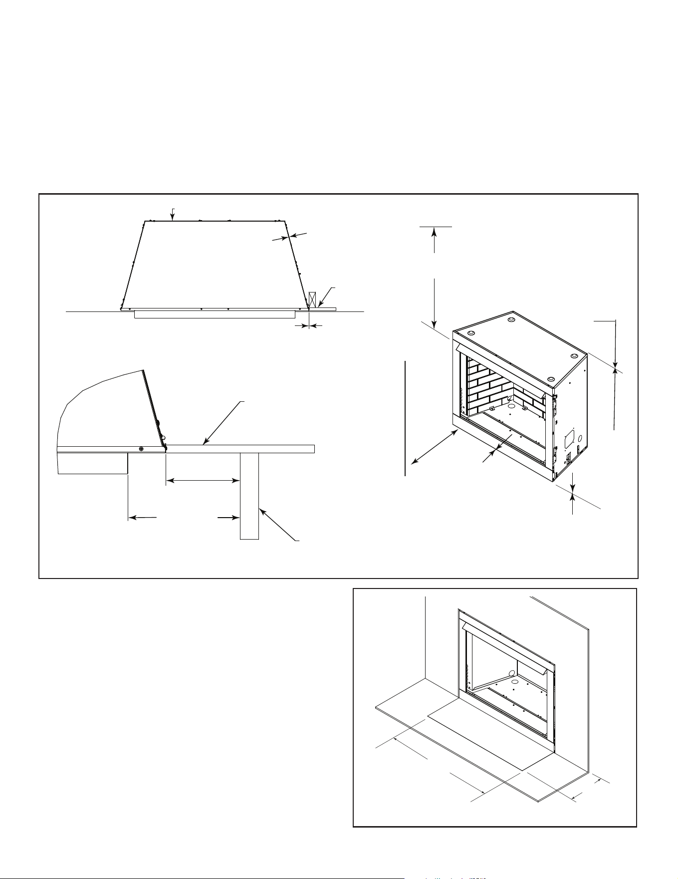
D. Clearances to Combustibles
Carefully select the best location for installation of your
vent-free rebox. The following factors should be taken
into consideration:
• Clearance to side walls and ceiling. Minimum clearances
to combustibles must be maintained.
• Location must not be aected by drafts caused by
kitchen exhaust fans, ceiling fans, return air registers for
forced air furnaces / air conditioners, windows or doors.
Figure 3.4 Clearances to Combustibles
• Installation must provide adequate ventilation and com-
bustion air.
• Location should be out of high trac or windy or drafty
areas.
• DO NOT INSTALL WHERE CURTAINS, FURNITURE,
CLOTHING OR OTHER FLAMMABLE OBJECTS ARE
LESS THAN 36" FROM FRONT OF FIREBOX.
• Never obstruct the front opening of the vent-free rebox
or restrict the ow of combustion and ventilation air.
0" in to back
0" in to side
0 in
Drywall
Combustible flooring may be installed next to the front of the appliance.
(No carpet or vinyl within 14 inches)
6 in. (152 mm) min.
9 in (229 mm) min.
(from firebox opening)
Drywall
Perpendicular
Wall
36 in
(914 mm)
Combustible Object
42 in to ceiling
(1067 mm)
0 in to floor
0 in to standoffs
Minimum Hearth Requirement -
0 in. Note: For installations with
vinyl flooring, special clearance
recommendations apply. See
section 3D Vinyl Flooring.
Vinyl Flooring
Vinyl Flooring is sensitive to heat. A 14 inch minimum depth
hearth extension is recommended when using vinyl ooring
up to the wall. See Figure 3.5.
NOTICE: Clearances that do not meet the minimum guide-
lines could result in damage or buckling to the vinyl ooring
and is done at the installer's risk.
Hearth and Home Technologies does not recommend
adhesive based vinyl ooring due to thermal expansion.
Floating-style ooring can be used, but will reach tempera-
tures up to 110°F in a room with ambient temperature of
70°F. Consult ooring specications to ensure compatibility.
Figure 3.5 Vinyl Flooring Exception
Vinyl Flooring
Firebox width min.
14 in. min.
10
Outdoor Lifestyles • VOFB36/42 Installation Manual • 4153-901 • Rev B • 04/23
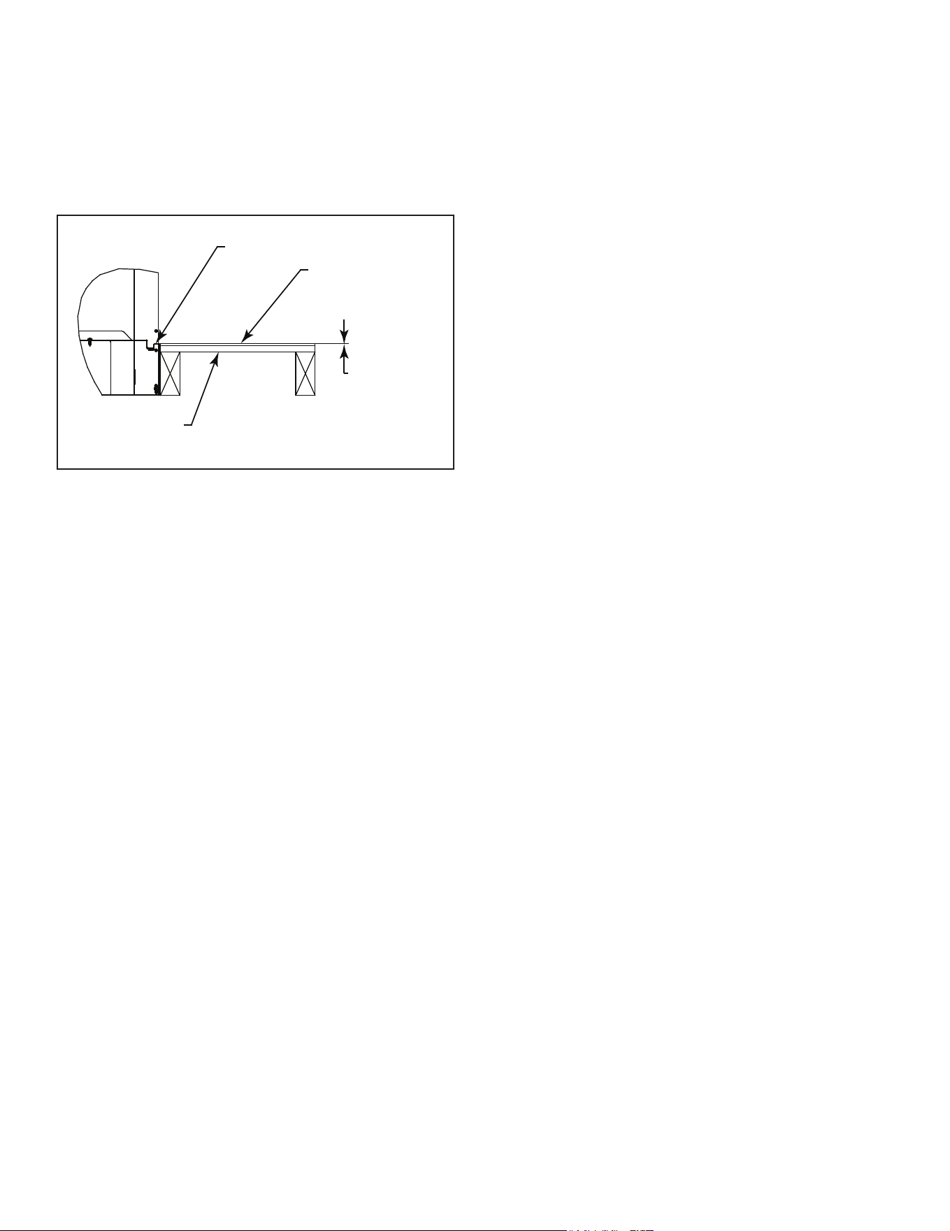
Raised Hearth Extension
A hearth extension may be used, but is not required for
these reboxes.
A combustible hearth extension can be constructed ush
with, but not above the rebox oor. On ush installa-
tions, carpet or vinyl is not allowed within 14 inches of
the rebox opening. See Figure 3.6.
Figure 3.6 Raised Hearth Extension
Firebox framing can be built before or after the appliance is
set in place. Construct rebox framing following Figure 3.3
for your specic installation requirements. Refer to Figure
3.1 on page 6 for rebox dimensions.
The rebox may be installed directly on a combustible
oor or raised on a platform. When the rebox is installed
directly on carpeting, tile, or other combustible material,
other than wood ooring, the rebox shall be installed on a
metal or wood panel extending the full width and depth of
the enclosure.
WARNING! Risk of Fire! DO NOT ll spaces around re-
box with insulation or other materials. This could cause a
re.
WARNING! Risk of Fire! The rebox must be installed
giving full consideration to the clearance and height re-
quirements identied in this manual.
E. Constructing the Appliance Chase
A chase is a vertical box-like structure built to enclose the
rebox.
NOTICE: These instructions are not substitutes for the
requirements of local building codes. Therefore, you MUST
check local building codes to determine the requirements
to these steps.
Chases should be constructed in the manner of all outside
walls of the home to prevent cold air drafting problems. The
chase should not break the outside building envelope in
any manner.
Walls, ceiling, base plate and cantilever oor of the chase
should be insulated. Vapor and air inltration barriers should
be installed in the chase as per regional codes for the rest
of the home. Additionally, in regions where cold air inltra-
tion may be an issue, the inside surfaces may be sheet
rocked and taped (or an equivalent method may be used)
to achieve maximum air tightness.
To further prevent drafts, gas line holes and other open-
ings should be caulked with caulk with a minimum of 300ºF
continuous exposure rating or stued with unfaced insulation.
If the rebox is being installed on a cement surface, a layer of
plywood may be placed underneath to prevent conducting cold
up into the room.
NOTICE: Install rebox on hard metal or wood surfaces
extending full width and depth. DO NOT install directly on
carpeting, vinyl, tile or any combustible material other than
wood.
WARNING! Risk of Fire! Maintain specied air space
clearances to rebox:
• Insulation and other materials must be secured to prevent
accidental contact.
• The chase must be properly blocked to prevent blown
insulation or other combustibles from entering and making
contact with rebox.
• Failure to maintain airspace may cause overheating and
a re.
0" Minimum
Combustible Platform
Raised Hearth Extension
(Combustibles allowed;
No carpet or vinyl within
14 inches)
Firebox Floor
11
Outdoor Lifestyles • VOFB36/42 Installation Manual • 4153-901 • Rev B • 04/23
A. Securing and Leveling the Firebox
WARNING! Risk of Fire! Prevent contact with:
• Sagging or loose insulation
• Insulation backing or plastic
• Framing and other combustible materials
Block openings into the chase to prevent entry of blown-
in insulation. Make sure insulation and other materials
are secured.
DO NOT notch the framing around the rebox standos.
Failure to maintain air space clearance could cause
overheating and re.
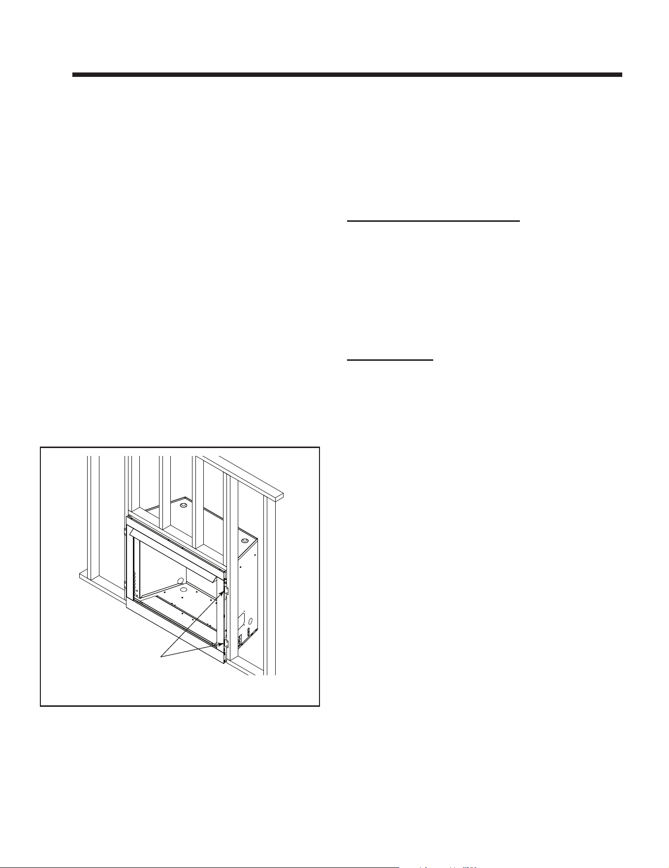
The diagram shows how to properly position and secure the
rebox. See Figure 4.1. Nailing tabs are provided to secure
the rebox to the framing members.
• Bend out nailing tabs on each side.
• Place the rebox into position.
• Keep nailing tabs ush with the framing.
• Level the rebox from side to side and front to back.
• Shim the rebox as necessary. It is acceptable to use
wood shims underneath the rebox.
• Secure the rebox to the framing by using nails or screws
through the nailing tabs.
Figure 4.1 Proper Positioning and Securing
of Firebox
4 4
Firebox Preparation
Nailing Tabs
(both sides)
B. Moisture Resistance
This outdoor appliance will shed moderate amounts of wa-
ter, but is not waterproof. This appliance must be enclosed
or covered with noncombustible nish material and all joints
sealed to prevent water inltration.
The rebox will not perform as an exterior wall. Moisture
penetration must be considered for construction that plac-
es the appliance in structure walls or on moisture sensitive
surfaces.
When installed on exterior walls: Hearth & Home Tech-
nologies recommends that the chase be constructed out-
side the structure’s weather envelope. Where the platform
meets the wall, use a ashing detail similar to that required
for attached decks. Chase platforms, including hearths
should slope away from the structure at 1/8 in. to 1/4 in. per
foot. The appliance can be shimmed level.
Install on wood, composite or non-combustible at surface,
extending full width and depth of the appliance to prevent
damage.
Water Drainage: The appliance is designed to operate
outdoors experiencing rain and other sources of moisture
that will enter the rebox. The appliance has built-in drain
holes in the base which will allow moisture to pass through
the bottom of the enclosure. When constructing the enclo-
sure, the builder must provide a means of draining water
from under the appliance and out of the structure. This can
be achieved by properly positioned drain holes, slots or
other means to allow water to exit at the lowest grade of
the structure. Choosing the location of the appliance is also
important so that an area that may experience excessive
water ow or standing water is avoided. In some cases a
drain pan is needed to ensure proper drainage. This can
be constructed from a corrosion resistant metal, or suitable
material for outdoor use with a water resistant membrane.
A slope of 1/4” per foot toward the drain ports of the struc-
ture is recommended. A drain pan can also be purchased
(ODGSDP-36) for the 36 inch appliance or the (ODGS-
DP-42) for the 42 inch appliance. For a at horizontal in-
stallation where the bottom of the appliance is sitting on the
hearth, use (ODGSDPFLT-36) OR (ODGSDPFLT-42).
Acceptable method for application of moisture membrane
material shown. See gifures 4.2, 4.3 and 4.4.
The appliance will not perform as an exterior wall. Mois-
ture penetration must be considered for construction that
places the appliance in structure walls or on moisture sen-
sitive surfaces.
12
Outdoor Lifestyles • VOFB36/42 Installation Manual • 4153-901 • Rev B • 04/23
►
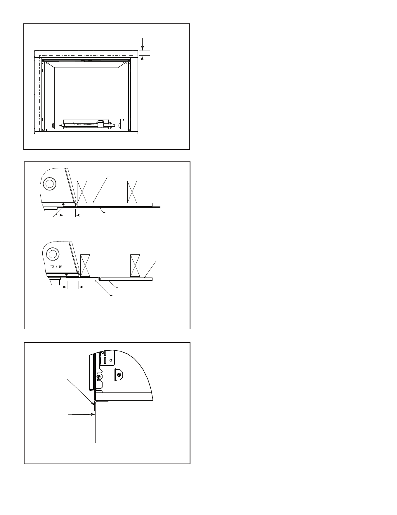
2 in.
(51 mm)
maximum
overlap
Figure 4.2 Membrane Overlap
Top view
House
wrap/water
membrane
No cement board with lathe
Lathe
Combustible sheathing
2 in.
Cement board no lathe
Non-combustible board
House wrap/water membrane
Combustible
sheathing
2 in.
Figure 4.3 Moisture Membrane
Side
View
Water
Membrane
Optional Drain
Pan
Figure 4.4 Side View of Drainage
13
Outdoor Lifestyles • VOFB36/42 Installation Manual • 4153-901 • Rev B • 04/23
A. Wiring Requirements
WARNING! Risk of Shock or Explosion! DO NOT wire
110-120 VAC to the valve. Incorrect wiring will damage
controls.
NOTICE: This firebox must be electrically wired and
grounded in accordance with local codes or, in the absence
of local codes, with National Electric Code ANSI/NFPA
70-latest edition.
• Wire the rebox junction box to unswitched 110-120 VAC.
This is required for proper operation of the rebox ignition.
• A 110-120 VAC circuit for this product must be protected
with ground-fault circuit-interrupter protection, in
compliance with the applicable electrical codes, when it is
installed in locations such as in bathrooms or near sinks.
• Low voltage and 110-120 VAC voltage cannot be shared
within the same wall box.
5 5
Electrical Information
B. Wiring the Junction Box
Junction box wiring on this rebox can be done from ei-
ther inside or outside of the rebox. However, for ease of
installation, it is recommended that the junction box be
wired from outside of the rebox.
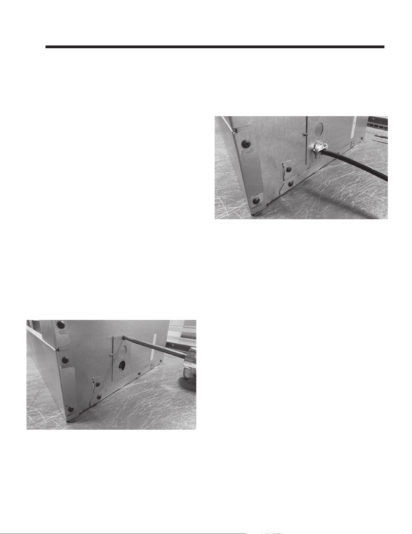
If the junction box is wired from OUTSIDE rebox:
• Remove the screw attaching the junction box cover to the
outer shell. Pull junction box cover out to disengage it
from the outer shell. See Figures 5.1.
Figure 5.1 Junction Box Cover Removal
• Install electrical wires from outside the appliance
through the hole in the cover plate and secure wires
with a Romex connector.
• Make all necessary wire connections to the junction
box and reattach the cover plate to rebox outer shell.
See Figure 5.2.
C. Electrical Service and Repair
WARNING! Risk of Shock! Label all wires prior to dis-
connection when servicing controls. Wiring errors could
cause improper and dangerous operation. Verify proper
operation after servicing.
WARNING! Risk of Shock! Replace damaged wire with
type 105º C rated wire. Wire must have high temperature
insulation.
Figure 5.2 Reattaching Junction Box Cover
14
Outdoor Lifestyles • VOFB36/42 Installation Manual • 4153-901 • Rev B • 04/23
A. Fuel Type
Check gas type: The gas supply must be the same as
stated on the appliance rating plate. If the gas supply is
dierent, DO NOT INSTALL THE APPLIANCE. Contact
your dealer for the correct model.
B. Gas Pressure
• Optimum appliance performance requires proper input
pressures.
• Gas line sizing requirements will be determined in ANSI
Z223.1 National Fuel Gas Code in the USA.
• Pressure requirements are:
C. Gas Connection
• Reference Section 3 for location of gas line access in
appliance.
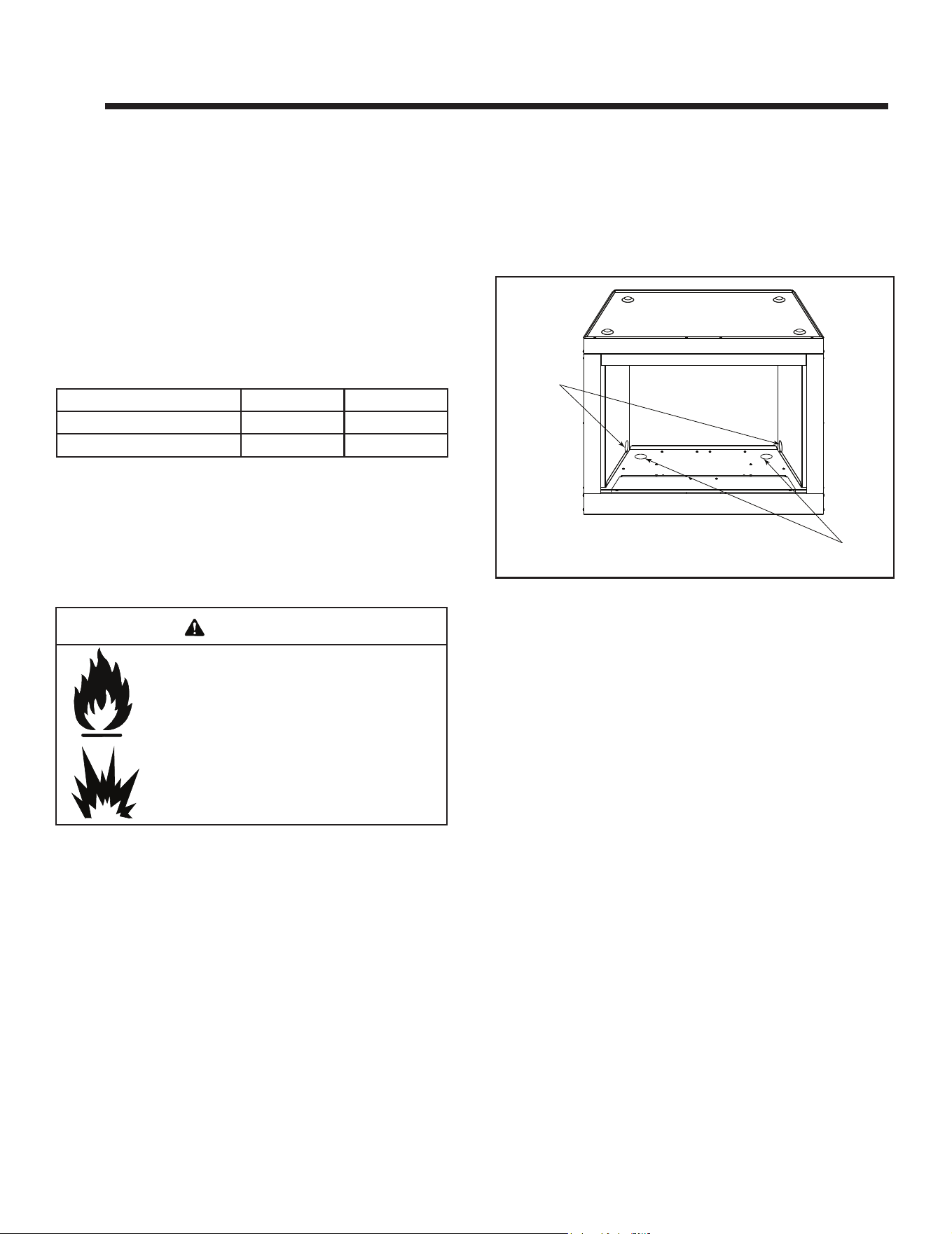
• The gas line may enter from the left side or right side of
the rebox. Gas knockouts are provided on both side of
the rebox, as well as on the rebox bottom. See Figure
6.1.
WARNING! Risk of Fire or Explosion! High pressure
will damage valve. Low pressure could cause explosion.
• Verify inlet pressures. Verify minimum pressures when
other household gas appliances are operating.
• Install regulator upstream of valve if line pressure is
greater than 1/2 psig.
Gas Pressure Natural Gas Propane
Minimum inlet pressure 5.0 in. w.c. 11.0 in. w.c.
Maximum inlet pressure 10.0 in. w.c. 13.0 in. w.c.
Note: Have the gas supply line installed in accordance with
local codes, if any. If not, follow ANSI Z223.1. Installation
should be done by a qualied installer approved and/or
licensed as required by the locality. (In the Commonwealth
of Massachusetts installation must be performed by a
licensed plumber or gas tter).
Note: A listed (and Commonwealth of Massachusetts ap-
proved) 1/2 in. (13 mm) T-handle manual shut-o valve
must be installed upstream of the appliance. A union tee
and plugged 1/8" NPT pressure tapping point should also
be installed upstream of the appliance.
IMPORTANT: Install manual shut-o valve (equipment
shuto valve) in an accessible location. The manual
shut-o valve is for turning on or shutting o the gas to
the rebox.
Fire Risk.
Explosion Hazard.
High pressure will damage valve.
• Disconnect gas supply piping BEFORE
pressure testing gas line at test pressures
above 1/2 psig.
• Close the manual shuto valve BEFORE
pressure testing gas line at test pressures
equal to or less than 1/2 psig.
WARNING
6 6
Gas Information
• The gap between supply piping and gas access hole may
be caulked with caulk with a minimum of 300ºF continuous
exposure rating or stued with non-combustible, unfaced
insulation to prevent cold air inltration.
• Ensure that gas line does not come in contact with outer
wrap of the rebox. Follow local codes.
• Pipe incoming gas line into rebox.
• Refer to vent-free gas appliance installation instructions
for gas connection and lighting instructions.
WARNING! Risk of Fire or Explosion! Support control
when attaching pipe to prevent bending gas line.
• A small amount of air will be in the gas supply lines.
WARNING! Risk of Fire or Explosion! Gas build-up
during line purge could ignite.
• Purge should be performed by qualified service
technician.
• Ensure adequate ventilation.
• Ensure there are no ignition sources such as sparks or
open ames.
Light the appliance. It will take a short time for air to purge
from lines. When purging is complete the appliance will
light and operate normally.
WARNING! Risk of Fire, Explosion or Asphyxiation!
Check all ttings and connections with a non-corrosive
commercially available leak-check solution. DO NOT use
open ame. Fittings and connections could have loosened
during shipping and handling.
Figure 6.1
Gas Access
Holes, Side
Gas Access Holes, Hearth
15
Outdoor Lifestyles • VOFB36/42 Installation Manual • 4153-901 • Rev B • 04/23
7 7
Finishing
A. Facing Material
WARNING! Risk of Fire! Metal front faces may be cov-
ered with non-combustible materials only.
• Firebox metal front faces may be covered with non-
combustible facing and/or nishing materials up to a
maximum thickness of 3 inches.
• Facing and/or nishing materials must not interfere with
air ow through the front of the rebox.
• Facing and/or nishing materials must never overhang
into the rebox opening.
• See Figures 7.1 and 7.2 for combustible and non-
combustible mantle and mantle leg clearance
requirements.
• Maintain all listed clearances when applying combustible
materials.
• Seal joints between the nished wall and rebox top and
sides using a 300º F minimum sealant.
NOTICE: Surface temperatures around the rebox will
become warm while the rebox is in operation. Ensure
nishing materials used for all surfaces (oor, walls, mantels,
etc.) will withstand temperatures up to 190°F.
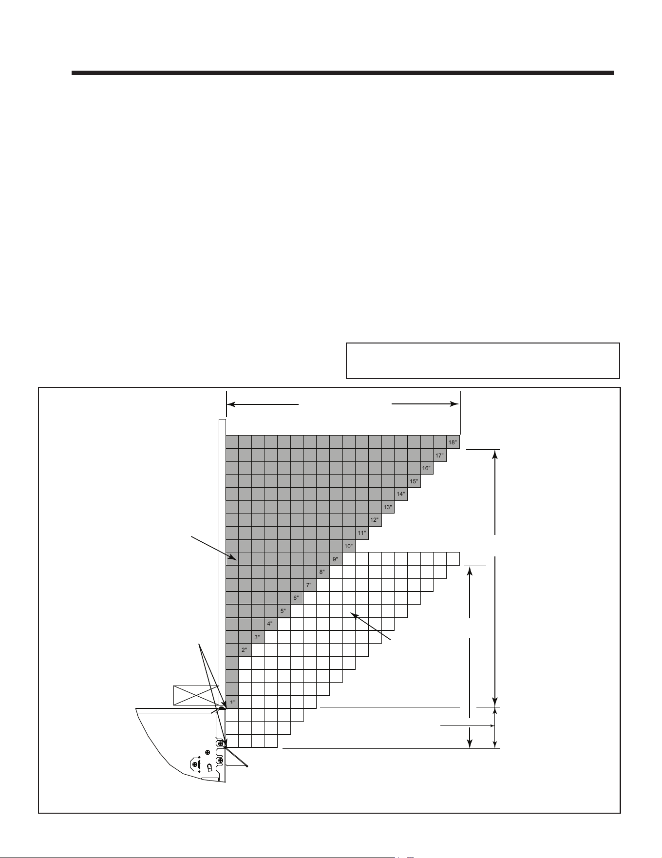
B. Mantel and Wall Projections
WARNING! Risk of Fire! Comply with all minimum clear-
ances as specied.
Combustible/Noncombustible Mantels
Figure 7.1 Minimum Vertical and Maximum Horizontal Dimensions of Combustible and Noncombustible
Note: Mantel Measurement is taken from top of
the rebox opening, NOT the top of the unit.
• Reducing non-combustible mantel and/or mantel leg
clearances closer than those listed in this manual
requires the use of non-combustible construction
materials (eg: steel studs, concrete boards, etc.) to a
minimum height of 12 inches (305 mm) above the listed
framing height.
Note: Reducing clearances further requires non-combustible construction materials (eg: steel studs, durock, etc) to a height of 12 inches above the framing height.
Seal joint with
non-combustible
sealant to
prevent heat
from being
drawn into the
wall cavity.
Gray area is
combustible
material
18 in. Maximum
3 in.
Min.
(Combustible
Mantle)
14 in.
20 in.
White area is
non-combustible
material
Measured from top of appliance opening
1"
2"
3"
4"
5"
6"
7"
8"
9"
10"
11"
12"
13"
14"
15"
16"
17"
18"
1"
2"
3"
4"
5"
6"
7"
8"
9"
10"
11"
12"
13"
14"
15"
16"
17"
18"
WARNING! Risk of Fire! DO NOT apply combustible ma-
terials beyond the minimum clearances. Comply with all
minimum clearances to combustibles as specied in this
manual. Overlapping materials could ignite and may inter-
fere with proper operation.
16
Outdoor Lifestyles • VOFB36/42 Installation Manual • 4153-901 • Rev B • 04/23
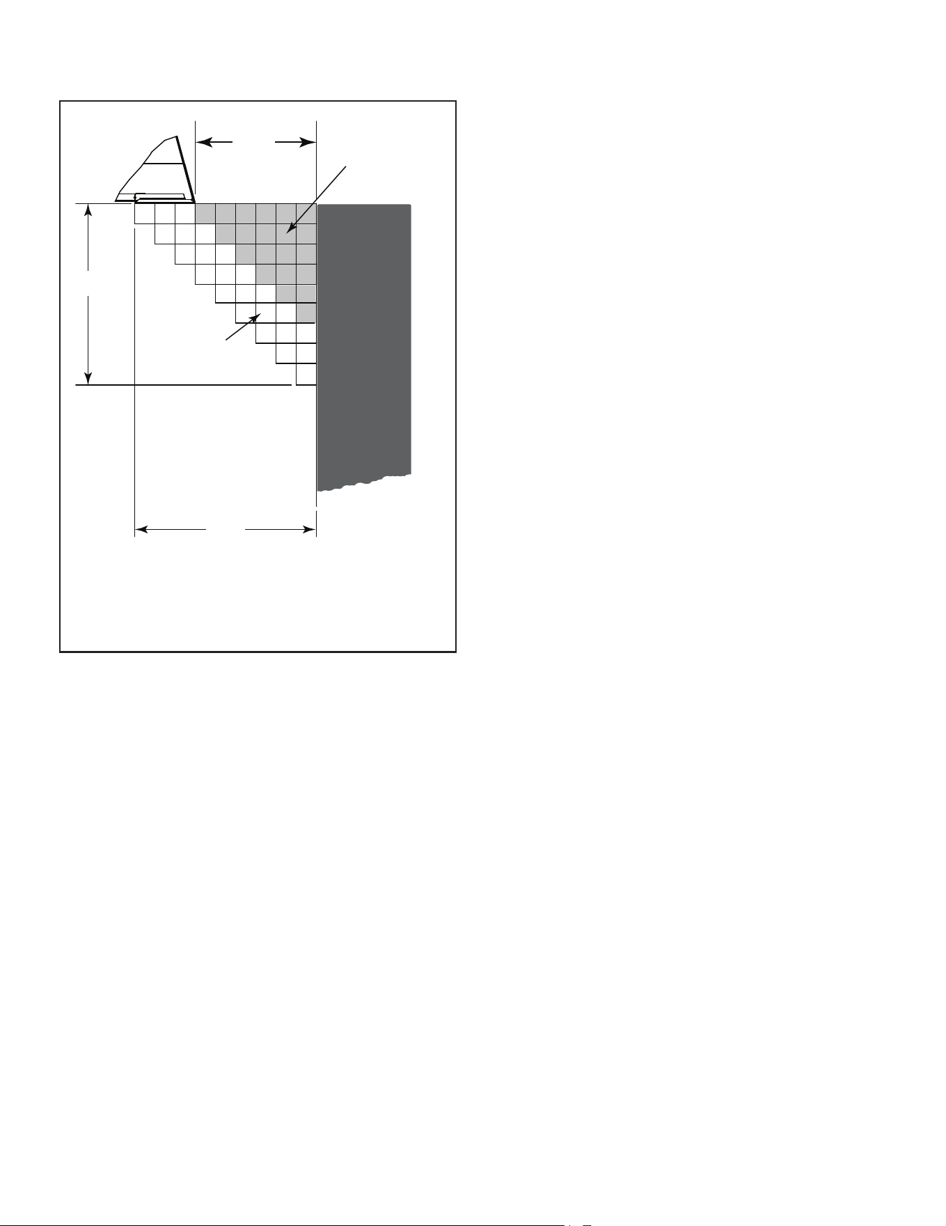
Figure 7.2 Combustible & Non-Combustible Mantel
Leg or Wall Projections
Combustible or Non-Combustible Mantel Legs or
Wall Projections
C. Decorative Fronts
Only decorative fronts certied for use with this rebox
model may be used. Contact your dealer for a list of deco-
rative fronts that may be used.
Minimum Side Wall
Unit
Gray area is
combustible
material
White area is
non-combustible
material only
1"
2"
3"
4"
5"
6"
7"
8"
9"
1"
2"
3"
4"
5"
6"
9.00”
6.00”
9.00”
17
Outdoor Lifestyles • VOFB36/42 Installation Manual • 4153-901 • Rev B • 04/23
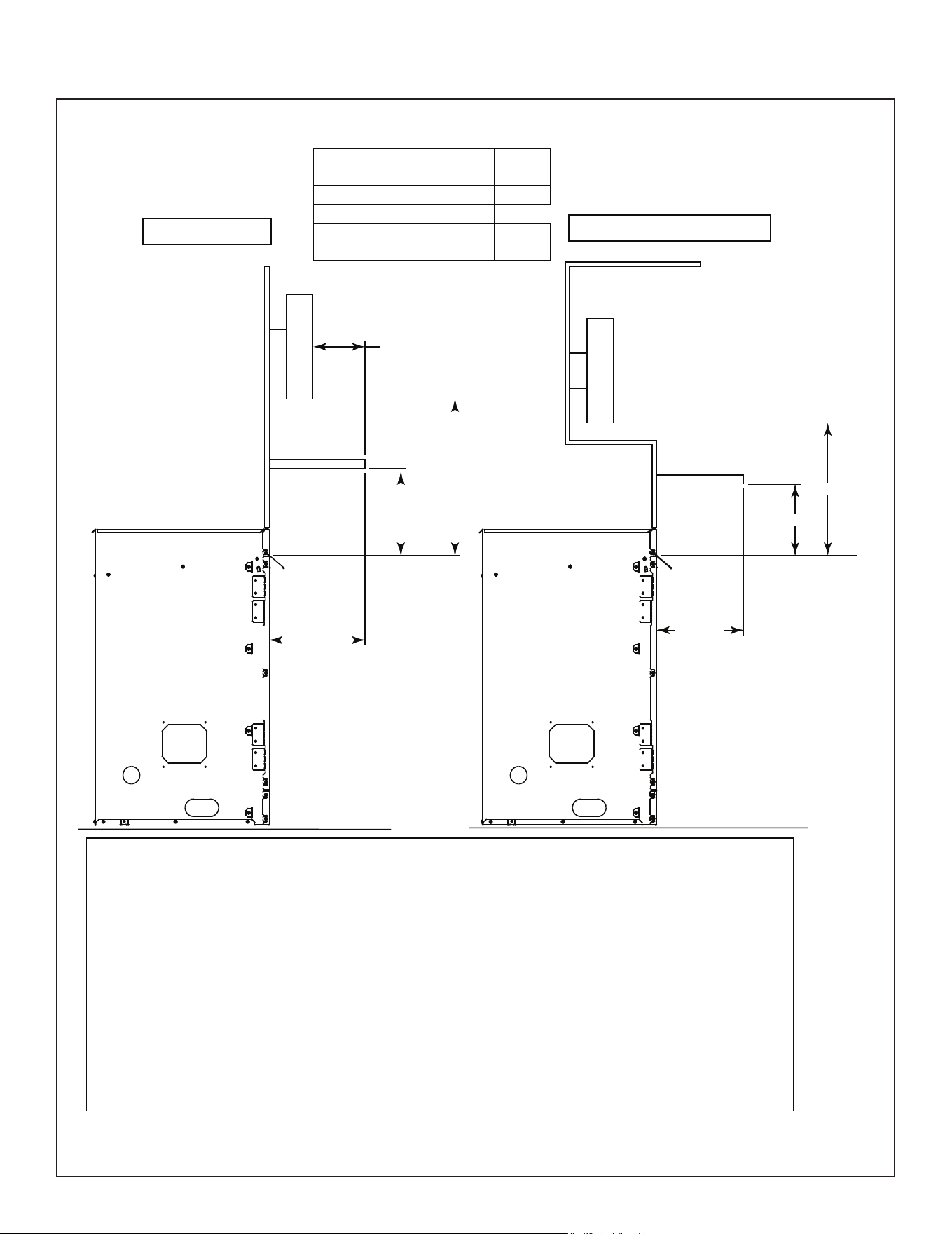
Figure 7.3 Good Faith Clearances
D. TV Good Faith Guidelines.
Combus�ble Mantel
A
inch
17.00
mm
432
Non-Combus�ble Mantel
inch
12.00
mm
305
Good Faith Guidelines for TV Installa�on’s above a Typical Gas Fireplace
TV on the wall
TV recessed into the wall
Notes:
1. These are good faith recommended clearances only and not a guarantee of compliance with all TV
manufacturers’ maximum allowable operating temperatures.
2. Since every home has unique air ow characteristics and maximum allowable operating temperatures
can vary from manufacturer to manufacturer and from model to model, actual TV temperatures should be
validated at the time of each installation. TVs should not be used in situations where the actual TV
temperature exceeds the manufacturers’ maximum allowable operating temperatures identied in the
TV’s technical specications. Contact the TV’s manufacturer directly if you cannot locate this information
or have questions regarding the information.
3. Mantel height and depth must conform to mantel requirements specied in the installation manual.
4. “A” dimension taken from the top of the appliance opening.
5. Suggestions on how to further reduce TV temperatures:
-Increase “A” and/or 24” minimum TV height dimensions.
6" Min.
A Min.
24" Min.
12" Min.
TV
24" Min.
A Min.
12" Min.
TV
18
Outdoor Lifestyles • VOFB36/42 Installation Manual • 4153-901 • Rev B • 04/23
8 8
Firebox Setup
A. Remove the Shipping Materials
Remove the shrink lm, corrugated top cap, bottom cap
and column protectors from the rebox.
Remove shipping materials from inside or underneath the
rebox.
B. Clean the Firebox
• Clean/vacuum any sawdust that may have accumu-
lated inside the rebox.
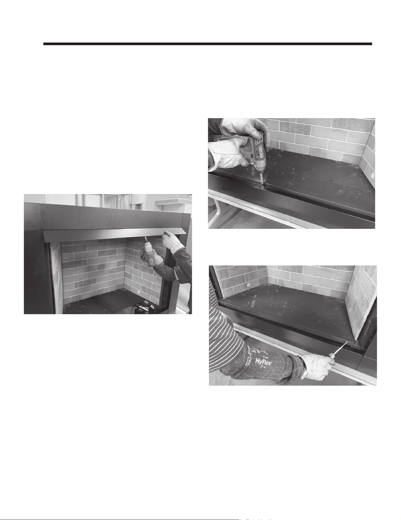
C. Hood Installation
WARNING: A hood is furnished with each rebox and
MUST be installed for safe operation.
Locate the (6) screws, (4 on the top and 1 on each
end),slide hood into position and secure. See Figure 8.1.
Figure 8.1
WARNING! Risk of Fire! The rebox hood must not be
modied or replaced with a hood that may be provided with
the vent free appliance.
D. Adjustable Firebox Supports
This rebox is provided with adjustable supports to allow
for proper support of the rebox bottom and reduced sag-
ging caused by heavy concrete logs.
To adjust rebox supports:
1. Remove (2) screws securing Lower Access Panel.
See Figure 8.2.
Figure 8.2
2. Using a at screwdriver, lift gently on Lower Access
Panel. See Figure 8.3.
Figure 8.3
19
Outdoor Lifestyles • VOFB36/42 Installation Manual • 4153-901 • Rev B • 04/23
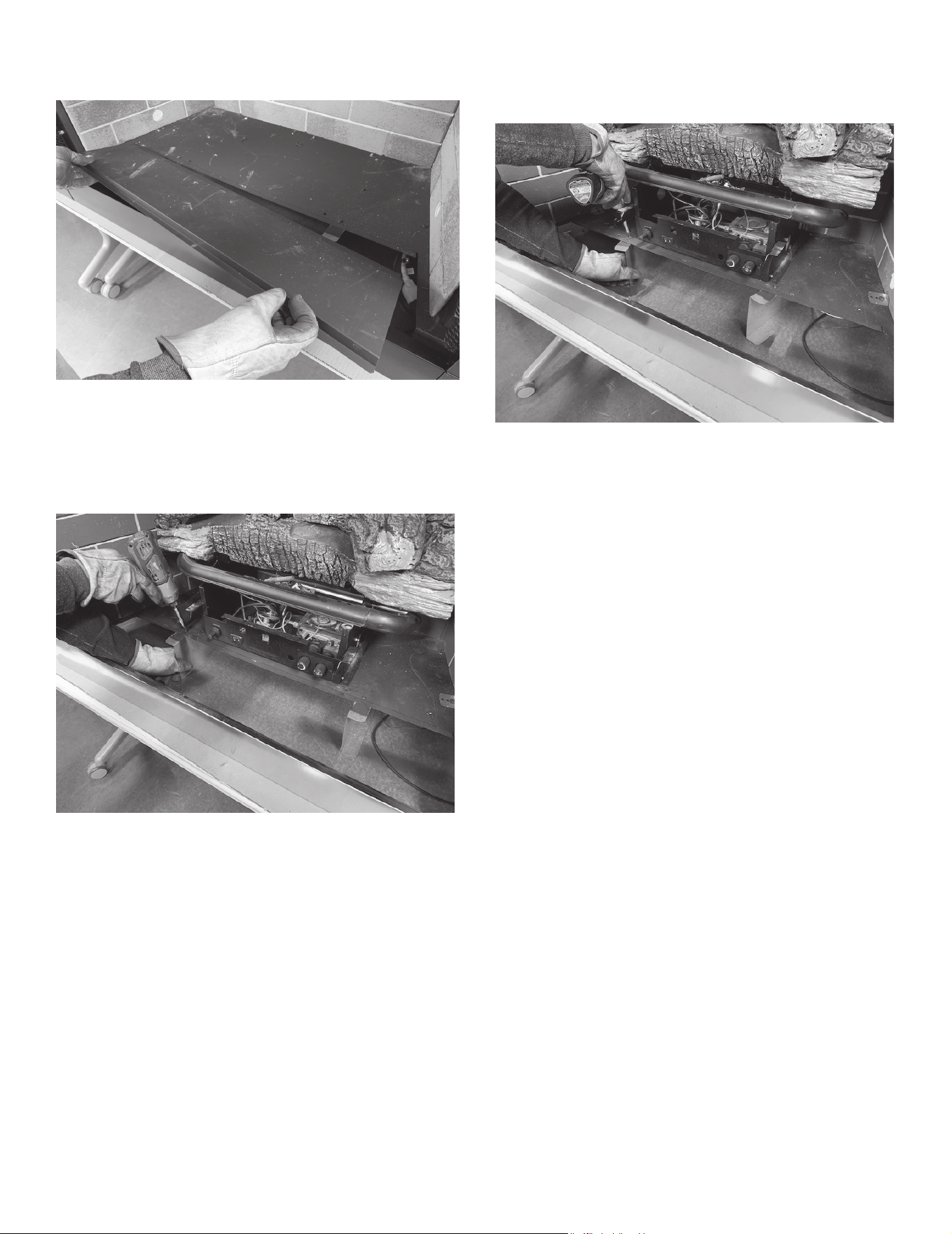
1. Pull Lower Access Panel forward to disengage from
Firebox Bottom, set aside. See Figure 8.4.
2. Remove (2) screws securing the front edge of both the
right and left rebox supports. See Figure 8.5.
3. Rotate the right and left rebox support towards the
center until screw holes align and reinstall (2) screws
previously removed. See Figure 8.6.
Note: The front edge of the rebox supports may be ad-
justed in or out, if needed, to provide the best support for
the selected log set. Once the rebox supports are prop-
erly located, to provide maximum support, the front edge
MUST be secured with a minimum of (1) screw each. The
rear edge of the rebox supports should not be altered
from the factory setting.
Figure 8.4
Figure 8.5
Figure 8.6
20
Outdoor Lifestyles • VOFB36/42 Installation Manual • 4153-901 • Rev B • 04/23

A. Optional Accessories
9 9
Reference Materials
Optional Screen Front: VOFBSD-36, VOFBSD-42
Optional Drain Pan: ODGSDP-36, ODGSDP-42
Optional Flat Drain Pan: ODGSDPFLT-36, ODGSDPFLT-42
Natural Burner Assembly: LUM-OD-NM
Propane Burner Assembly: LUM-OD-PM
21
Outdoor Lifestyles • VOFB36/42 Installation Manual • 4153-901 • Rev B • 04/23
►
B. Contact Information
– NOTES –
Outdoor Lifestyles, a brand of Hearth & Home Technologies
7571 215th Street West, Lakeville, MN 55044
www.hearthnhome.com
22
Outdoor Lifestyles • VOFB36/42 Installation Manual • 4153-901 • Rev B • 04/23