1
Owner’s Manual
Installation and Operation
DO NOT DISCARD THIS MANUAL
NOTICE
• Important operating
and maintenance
instructions included.
• Leave this manual with
party responsible for
use and operation.
• Read, understand
and follow these
instructions for safe
installation and
operation.
DO NOT
DISCARD
Fire Risk
• For use with solid wood fuel or decorative
gas appliance only.
• DO NOT install unvented gas logs.
WARNING
If the information in these instruc-
tions is not followed exactly, a
re may result causing property
damage, personal injury, or death.
• Donotstoreorusegasolineorotheram-
mable vapors and liquids in the vicinity of
this or any other appliance.
• Donotoverre.Overringwillvoidyour
warranty.
• Comply with all minimum clearances to
combustiblesasspecied.Failureto
complymaycausehousere.
WARNING
WARNING
Hot screen/mesh and glass doors will cause burns.
• DO NOT touch screen/mesh or glass doors until
cooled
• NEVER allow children to touch screen/mesh or glass
doors
• Keep children away
• CAREFULLY SUPERVISE children in same room as
replace.
• Alert children and adults to hazards of high
temperatures.
High temperatures may ignite clothing or other
ammable materials.
• Keep clothing, furniture, draperies and other
ammablematerialsaway.
HOT SURFACES!
Screen/mesh, glass doors
and other surfaces are hot
during operation AND cool
down.
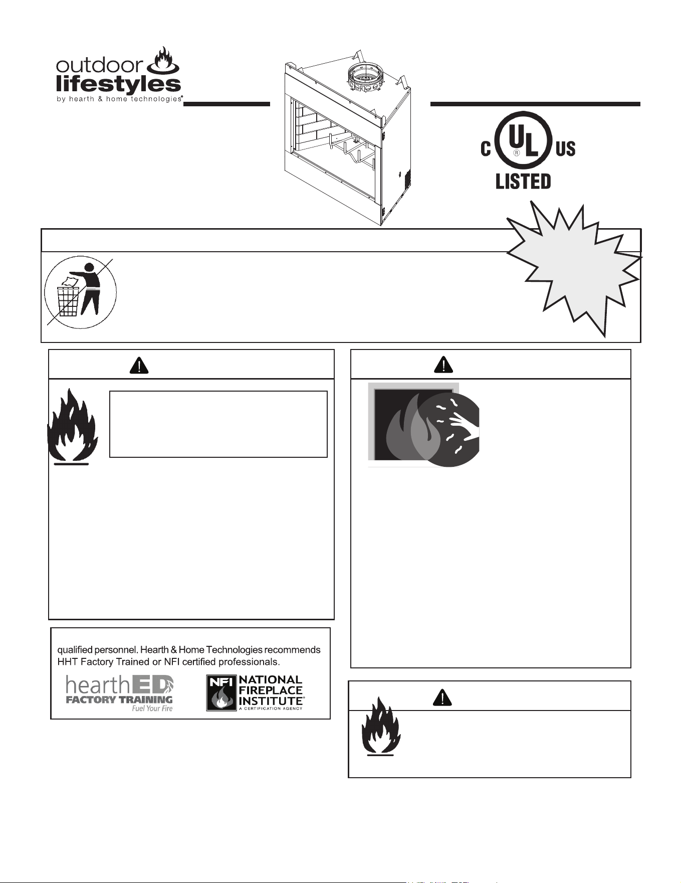
Models:
Outdoor Woodburning Fireplace
ODVILLA-36H-B
ODVILLA-36T-B
ODVILLA-42H-B
ODVILLA-42T-B
Installation and service of this appliance should be performed by
Outdoor Lifestyles by Hearth & Home Technologies • ODVILLA Wood Owners/Install • 4072-345 Rev B • 05/23
2
Read this manual before installing or operating this replace.
Please retain this owner’s manual for future reference.
Homeowner Reference Information
Model Name: Date purchased/installed:
Serial Number: Locationonreplace:
Dealership purchased from: Dealer phone:
Notes:
We recommend that you record the following pertinent
information about your replace:
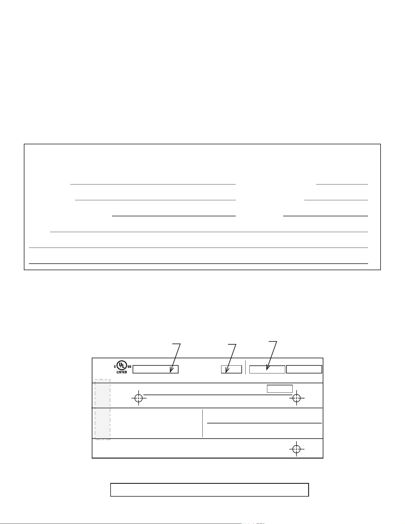
Listing Label Information/Location
Themodelinformationregardingyourspecicreplacecanbefoundontheratingplatelocatedonthesmokeshieldof
thereplace.
Congratulations!
Note: An arrow ( )foundinthetextsignieschangeincontent.
Outdoor Lifestyles by Hearth & Home Technologies • ODVILLA Wood Owners/Install • 4072-345 Rev B • 05/23
Congratulations on selecting a Outdoor Lifestyles wood
burningreplace.TheOutdoor Lifestylesreplaceyouhave
selected is designed to provide the utmost in safety, reliability
andeciency.
Astheownerofanewreplace,you’llwanttoreadandcarefully
followalloftheinstructionscontainedinthisowner’smanual.
Pay special attention to all cautions and warnings.
Thisowner’smanualshouldberetainedforfuturereference.
Wesuggestyoukeepitwithyourotherimportantdocuments
and product manuals.
Theinformationcontainedinthisowner’smanualunless
noted otherwise, applies to all models and gas control
systems.
Your new Outdoor Lifestyles wood burningreplace will
give you years of durable use and trouble-free enjoyment.
Welcome to the Outdoor Lifestyles family of replace
products!
Serial Number
Grate
Fireplace
Model
FIREPLACE NO.
MODEL NO.
MODEL NO.
MFG. DATE
WARNING: RISK OF
FIRE DAMAGE. REPLACE
GRATE WITH HEARTH & HOME
TECHNOLOGIES
OUTDOOR FIREPLACE INTENDED FOR USE WITH HEARTH & HOME TECHNOLOGIES LISTED FIREPLACE PARTS. SEE INSTALLATION AND
OPERATING INSTRUCTIONS FOR THIS MODEL. ONLY HEARTH & HOME TECHNOLOGIES GLASS DOOR KITS CAN BE INSTALLED ON THIS UNIT.
CLEARANCE TO
COMBUSTIBLES:
CHIMNEY
2 IN. MIN.
FIREBOX
IN.
MIN.
DO NOT OVERFIRE. USE ONLY: SOLID WOOD FUEL OR
LISTED DECORATIVE GAS APPLIANCE. DO NOT USE A
FIREPLACE INSERT OR OTHER PRODUCTS NOT
SPECIFIED FOR USE WITH THIS PRODUCT. IF DOORS
ARE USED OPERATE FIREPLACE WITH DOORS FULLY
OPEN OR CLOSED ONLY. WHEN BURNING A
DECORATIVE GAS APPLIANCE IN THE FIREPLACE,
ADJUST DAMPER TO THE FULLY OPEN POSITION.
WARNING! THIS FIREPLACE HAS NOT BEEN TESTED WITH AN UNVENTED
GAS LOG SET. TO REDUCE THE RISK OF FIRE OR INJURY, DO NOT
INSTALL AN UNVENTED GAS LOG SET INTO FIREPLACE.
WARNING! TO AVOID THE RISK OF DAMAGING FIREPLACE MATERIALS
AND INCREASING THE RISK OF SPREADING A FIRE DO NOT USE THE
FIREPLACE TO COOK OR WARM FOOD.
IF INSTALLATION OR OPERATING INSTRUCTIONS ARE MISSING
CONTACT: HEARTH & HOME TECHNOLOGIES
,
7571 215th Street West,Lakeville,MN55044
P.N.4021-723D

3
Safety Alert Key:
• DANGER! Indicates a hazardous situation which, if not avoided will result in death or serious injury.
• WARNING! Indicates a hazardous situation which, if not avoided could result in death or serious injury.
• CAUTION! Indicates a hazardous situation which, if not avoided, could result in minor or moderate injury.
• NOTICE:Indicatespracticeswhichmaycausedamagetothereplaceortoproperty.
!
Table of Contents
Congratulations! 2
Warranty 4
1 Listing and Code Approvals 6
A. ApplianceCertication 6
B. Non-CombustibleMaterials 6
C. CombustibleMaterials 6
User Guide
2 Operating Instructions 7
A. Your Fireplace 7
B. Seasoned Wood 8
C. Starting a Fire 8
D. Grate 8
E. Firescreen 8
F. Refractory 8
G. Glass Doors 9
H. Dual Cooling Air Kit (REQUIRED) 9
I. Vented Gas Log Sets & Gas Log Lighters 9
K. Clear Space 9
L. WoodFuel 10
3 Maintenance and Service 11
A. Disposal of Ashes 11
B. Chimney Inspection/Cleaning 11
C. CheckFireboxRefractory 12
D. Inspect Grate 12
E. Glass Cleaning 12
4 Troubleshooting Guide 13
5 Getting Started 14
Installer Guide
A. TypicalFireplaceSystem 14
B. Design and Installation Considerations 15
C. Moisture Resistance: 15
D. Tools and Supplies Needed 15
E. Fireplace System Requirements 15
F. Inspect Fireplace and Components 15
6 Framing & Clearances 16
A. SelectingFireplaceLocation 16
B. Clearances 17
C. Sidewalls/Surrounds 18
D. Frame the Fireplace 18
E. Chimney Requirements 19
7 Installation of Fireplace 20
A. PositiontheFireplace 20
B. PlaceProtectiveMetalHearthStrips 20
C. LevelFireplace 20
D. Install Cooling Air Hoods (PROVIDED) 21
8 Chimney Assembly 22
A. ChimneyRequirements 23
B. UsingOsets/Returns 24
C. Assemble Chimney Sections 25
D. Install Ceiling Firestops 25
E. InstallingtheAtticInsulationShield26
F. Cut out Hole in Roof 27
G. Complete Installation 27
H. Install Flashing 27
I. Chimney Termination Requirements 28
9 Chase Installations 29
A. Construct the Chase 29
B. InstallFireplace&Chimney 30
C. InstallChaseTop 30
D. InstallTerminationCap 31
10 Shrouds 33
A. RadiationShield 33
B. FieldConstructedShrouds 33
11 Finishing 35
A. Non-CombustibleMaterials 35
B. CombustibleMaterials 35
C. HearthExtension 35
D. FinishingMaterial 37
E. CombustibleMantel 39
F. Sidewalls/Surrounds 40
12 Accessories 41
A. GasLog/LighterProvision 41
13 Reference Materials 42
A. ApplianceDimensions/Weight 42
B. OptionalComponents 43
C. ChimneyComponents 44
D. ServiceParts 47-50
E. Contact Information 51
Outdoor Lifestyles by Hearth & Home Technologies • ODVILLA Wood Owners/Install • 4072-345 Rev B • 05/23
►
►
►

4
Limited Warranty
Outdoor Lifestyles Warranty - 2108-975C – 6/5/2019 - 1
Outdoor Lifestyles by Hearth & Home Technologies™
Limited Lifetime Warranty
Hearth & Home Technologies (“HHT”) extends the following warranty for all Outdoor Lifestyles by HHT™
brand products (“Products”) that are purchased from an HHT authorized dealer.
WARRANTY COVERAGE:
HHT warrants to the original owner of the Product at the site of installation, and to any transferee taking
ownership of the Product at the site of installation within one year following the date of original purchase,
that the Product will be free from defects in materials and workmanship at the time of manufacture. After
installation, if covered components manufactured by HHT are found to be defective in materials or
workmanship during the applicable warranty period, HHT will, at its option, repair or replace the covered
components. This warranty is subject to conditions, exclusions and limitations as described below.
WARRANTY PERIOD:
The warranty period begins on the earlier of: (i) the date of invoice for the Product;
(ii) in the case of new home construction, the date of first occupancy of the residence or six months after
the date of sale of the Product by an HHT authorized dealer, whichever occurs first; or (iii) the date 24
months following the date of Product shipment from HHT, regardless of the invoice or occupancy date.
WARRANTY CONDITIONS:
• The Limited Lifetime Warranty covers Products that are purchased through a HHT authorized
dealer or distributor. A list of HHT authorized dealers is available on the HHT branded websites.
• This warranty is only valid while the Product remains at the site of original installation.
• Contact your installing dealer for warranty service. If the installing dealer is unable to provide
necessary parts, contact the nearest HHT authorized dealer. Additional service fees may apply if
you are seeking warranty service from a dealer other than the dealer from whom you originally
purchased the Product.
• Check with your dealer in advance for any costs to you when arranging a warranty call. Travel
and shipping charges for parts are not covered by this warranty.
• The Product body, metal firebox and heat exchanger carry the Limited Lifetime Warranty from the
date of installation.
• The following components do not carry the Limited Lifetime Warranty but are warranted as follows:
o One Year from Date of Installation:
▪ Gas and Electrical Components or Gaskets
▪ Nickel Plated Materials
• Excludes tarnishing
▪ Glass Breakage, Logs/Refractory/Glass Panels due to thermal breakage
• Surface, hairline cracks, scratches and slight color changes are not covered
▪ Venting, optional accessories, optional glass doors
▪ Labor Associated with Warranty Service Work
WARRANTY EXCLUSIONS:
This warranty does not cover the following:
• Changes in surface finishes as a result of normal use. As a heating appliance, some changes in
color of interior and exterior surface finishes may occur; this is not a flaw and not covered under
warranty.
• Damage to printed, plated, or enameled surfaces caused by fingerprints, accidents, misuse,
scratches, melted items, or other external sources and residues left on surfaces from the use of
abrasive cleaners or polishes.
• Repair or replacement of parts that are subject to normal wear and tear during the warranty
period. These parts include: paint, firebricks, grates, flame guides and the discoloration of glass.
• Minor expansion, contraction, or movement of certain parts causing noise. These conditions are
normal and complaints related to this noise are not covered by this warranty.
Outdoor Lifestyles by Hearth & Home Technologies • ODVILLA Wood Owners/Install • 4072-345 Rev B • 05/23

5
Limited Warranty (continued)
Outdoor Lifestyles Warranty - 2108-975C – 6/5/2019 - 2
• Damages resulting from: (1) failure to install, operate, or maintain the Product in accordance with
the installation instructions, operating instructions, and listing agent identification label furnished
with the Product; (2) failure to install the Product in accordance with local building codes; (3)
shipping or improper handling; (4) improper operation, abuse, misuse, continued operation with
damaged, corroded or failed components, accident, or incorrectly performed repairs; (5) inad-
equate ventilation, negative pressure or environmental conditions, including, without limitation:
hail, snow, ice, fallen branches, flooding, water damage and fading of color; (6) use of fuels other
than those specified in the operating instructions; (7) installation or use of components not
supplied with the Product or any other components not expressly authorized and approved by
HHT; (8) modification of the Product not expressly authorized and approved by HHT in writing;
and/or (9) interruptions or fluctuations of electrical power supply to the Product.
• Non-HHT venting components, hearth components or other accessories used in conjunction with
the Product.
• Any part of a pre-existing fireplace system in which an insert or a decorative gas appliance is
installed.
• The Product’s capability to heat the desired space. Information is provided to assist the consumer
and the dealer in selecting the proper appliance for the application. Consideration must be given
to the Product’s location and configuration and environmental conditions.
This warranty is void if:
• The Product has been over-fired or operated in atmospheres contaminated by chlorine, fluorine,
or other damaging chemicals. Over-firing can be identified by, but not limited to, warped plates or
tubes, rust colored cast iron, bubbling, cracking and discoloration of steel or enamel finishes and
cracking or spalling of refractory or cementitious materials.
• The Product is subjected to prolonged periods of dampness, condensation, ice or snow.
• There is any damage to the Product or other components due to water or weather damage
which is the result of, but not limited to, improper chimney or venting installation.
LIMITATIONS OF LIABILITY:
Repair or replacement in accordance with the provisions of this warranty will be the owner’s exclusive
remedy for and will constitute HHT’s sole obligation under this warranty, under any other warranty
(express or implied), or in contract, tort or otherwise; provided, however, that if HHT is unable to provide
repair or replacement in an expedient and cost effective manner, HHT may discharge all such obligations
by refunding the purchase price of the Product. No employee, agent, dealer, or other person is authorized
to give any warranty on behalf of HHT. TO THE EXTENT ALLOWED BY LAW, HHT MAKES NO OTHER
WARRANTY, EXPRESS OR IMPLIED, INCLUDING ANY WARRANTY OF MERCHANTABILITY OR
FITNESS FOR A PARTICULAR PURPOSE. HHT WILL NOT BE LIABLE FOR ANY CONSEQUENTIAL
OR INCIDENTAL DAMAGES ARISING OUT OF DEFECTS IN OR USE OF THE PRODUCTS. Some
states do not allow exclusions or limitation of incidental or consequential damages, so these limitations
may not apply to you. This warranty gives you specific rights; you also may have other rights, which vary
from state to state. The duration of any implied warranty is limited to the duration of the warranty period
specified herein.
Outdoor Lifestyles by Hearth & Home Technologies • ODVILLA Wood Owners/Install • 4072-345 Rev B • 05/23
6
1 1
Listing and Code Approvals
NOTICE: This fireplace is tested and approved as a
decorative replace. It should not be factored as a primary
heat source in residential heating calculations.
WARNING! Risk of Fire! Hearth & Home Technologies
disclaims any responsibility for, and the warranty and
agency listing will be voided by the following actions.
DO NOT:
• install or operate damaged replace
• modify replace
• install other than as instructed by Hearth & Home
Technologies
• operate the replace without fully assembling all
components
• overre
• install an unvented gas log set
• install any component not approved by Hearth & Home
Technologies
• install parts or components not Listed or approved
Improper installation, adjustment, alteration, service or
maintenance can cause injury or property damage. For
assistance or additional information, consult a qualied
installer, service agency or your dealer.
B. Non-Combustible Materials
• Materials which will not ignite and burn, composed of
any combination of the following:
- Steel - Iron
- Brick - Tile
- Concrete - Slate
- Glass - Plasters
• Materials reported as passing ASTM E 136, Standard
Test Method for Behavior of Metals, in a Vertical Tube
Furnace at 750° C
C. Combustible Materials
• Materials made of or surfaced with any of the following
materials:
- Wood - Compressed paper
- Plantbers - Plastic
• Anymaterialthatcanigniteandburn;ameproofedor
not, plastered or un-plastered
Outdoor Lifestyles by Hearth & Home Technologies • ODVILLA Wood Owners/Install • 4072-345 Rev B • 05/23
A. Appliance Certication
Outdoor Lifestyles is aregistered trademark of Hearth &
Home Technologies Inc.
Thisreplacesystemhasbeentestedandlistedinaccor-
dance with UL 127 and CAN/ULC-S610-M87 standards
by Underwriters Laboratories Inc. for installation and op-
eration in the United States and Canada.
Thisreplacehasbeentestedandlistedforusewiththe
optionalcomponentsspeciedinthismanual.Theseop-
tional components may be purchased separately and in-
stalled at a later date.
Fire Risk
WARNING
WARNING! TO AVOID THE RISK OF DAMAGING FIRE-
PLACE MATERIALS AND INCREASING THE RISK OF
SPREADING A FIRE, DO NOT USE THE FIREPLACE TO
COOK OR WARM FOOD.
WARNING: This product and the fuels
used to operate this product (wood and
wood pellets), and the products of combus-
tion of such fuels, can expose you to chemi-
cals including carbon black, which is known
to the State of California to cause cancer
and carbon monoxide, which is known to
the State of California to cause birth defects
or other reproductive harm. For more infor-
mation go to: www.P65Warnings.ca.gov.
7
2 2
Operating Instructions
WARNING! DO NOT operate replace before reading and understanding operating instructions. Failure to operate replace
according to operating instructions could cause re or injury.
User Guide
WARNING
Hot glass will cause burns.
• DO NOT touch glass until it is cooled
• NEVER allow children to touch glass
• Keep children away
• CAREFULLYSUPERVISEchildreninsameroomasreplace.
• Alert children and adults to hazards of high temperatures.
High temperatures may ignite clothing or other ammable materials.
• Keepclothing,furniture,draperiesandotherammablematerialsaway.
HOT SURFACES!
Glass and other surfaces are hot during operation AND cool down.
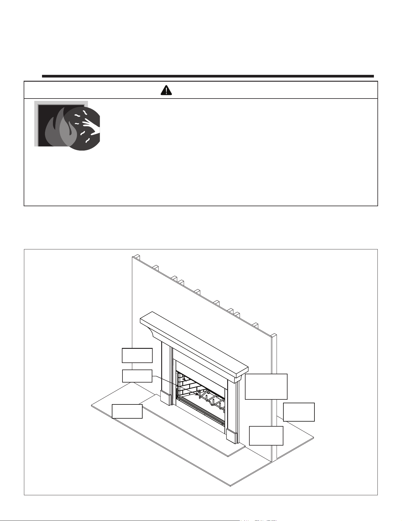
Figure 2.1 General Operating Parts
A. Your Fireplace
Ifyouexpectthatchildrenmaycomeintocontactwiththisreplace,werecommendabarriersuchasadecorativescreen.
See your dealer for suggestions.
Gas Log Set
Gas Log Lighters
(not shown)
Section 2.I.
Firescreen
(not shown)
Section 2.E.
Glass Doors
(not shown)
Section 2.K.
Grate
Section 2.D.
Refractory
Section 2.F..
Hearth
Clear Space
Section 2.K.
Wood Fuel
Section 2.L.
Mantel
Outdoor Lifestyles by Hearth & Home Technologies • ODVILLA Wood Owners/Install • 4072-345 Rev B • 05/23

8
• Therstthreeorfourresshouldbeofmoderatesizeto
allowtheoilsandbinderstobeburnedfromthereplace
and the refractory and paint to cure. You may notice
anindustrialodortherstfewres.Thisisconsidered
normal.
• Use well-seasoned wood.
• Place crumpled or twisted paper under the replace
grate.
• Looselyarrangekindlingorsmallpiecesofwoodtoform
a‘tent’onthereplacegrate.
• Pre-warmthe ue to establish a draft to help reduce
smokespillageduringstart-up.Holdarolleduppieceof
burningnewspaperundertheueforafewmoments.
• Lightthecrumpledpapertoignitethekindling.
• Add small pieces of wood until a hot bed of embers has
been established.
• Add a minimum of three average size pieces of split
rewood, placed to allow combustion air and ames
between them.
C. Starting a Fire
NOTICE: You must establish a good draft to prevent smoke
spillage into the room.
WARNING! Risk of Fire! Keep combustible materials,
gasoline and other ammable vapors and liquids clear of
the replace.
DO NOT:
• store ammable materials close to the replace
• use gasoline, lantern fuel, kerosene, charcoal lighter
uid or similar liquids to start or “freshen up” a re in this
replace.
Keep all ammable liquids well away from the replace while
it is in use. Combustible materials may ignite.
B. Seasoned Wood
Properly seasoned wood is important for successful op-
erationofyourreplace.Mostwoodburningreplaceprob-
lems are caused by burning wet, unseasoned wood.
Seasonedrewoodiswoodthatiscuttosize,splitandair
driedtoamoisturecontentofaround20%.
Imagineawoodenbucketthatweighsabouteightpounds.
Fillitwithagallonofwater,putitinthereplaceandtryto
burn it. This sounds ridiculous but that is exactly what you
are doing if you burn unseasoned wood.
Atreecutdownayearagoandnotsplitislikelytohave
almost as high a moisture content now as it did when it
was cut.
Please refer to Section 2.L for more detail.
CAUTION! Odors and vapors released during initial
operation may be irritating to sensitive individuals.
D. Grate
Thisreplaceisdesignedtobeusedwiththe gratesup-
plied with this unit or one approved by HHT. The grate will
break down over time and will need occasional replace-
ment.
WARNING! Risk of Fire! Use only the factory-supplied
integral grate.
• Keeps logs in place.
• Allows proper air circulation around the re.
E. Firescreen
Therescreenisprovidedtocontrolsparks.Keepit
closedwhenthereplaceisinuse.
WARNING! Risk of Fire or Burns!
• Screen will not prevent burning materials from falling
out.
• Screen pulls or handles may be hot.
F. Refractory
• The refractory is supplied to contain heat and provide
an attractive interior.
• Itwill breakdown over timeand willneed occasional
replacement.Smallhairlinecracksanddiscolorationare
normalanddonotaectitssafety.
• (SeerefractorymaintenanceSection3.C.)
WARNING! Risk of Fire! DO NOT burn replace with-
out refractory. Use only refractory supplied by Hearth &
Home Technologies, Inc.
Outdoor Lifestyles by Hearth & Home Technologies • ODVILLA Wood Owners/Install • 4072-345 Rev B • 05/23
9
FULLY OPEN
CORRECT
PARTLY CLOSED
INCORRECT
PARTLY OPEN
INCORRECT
FULLY CLOSED
CORRECT
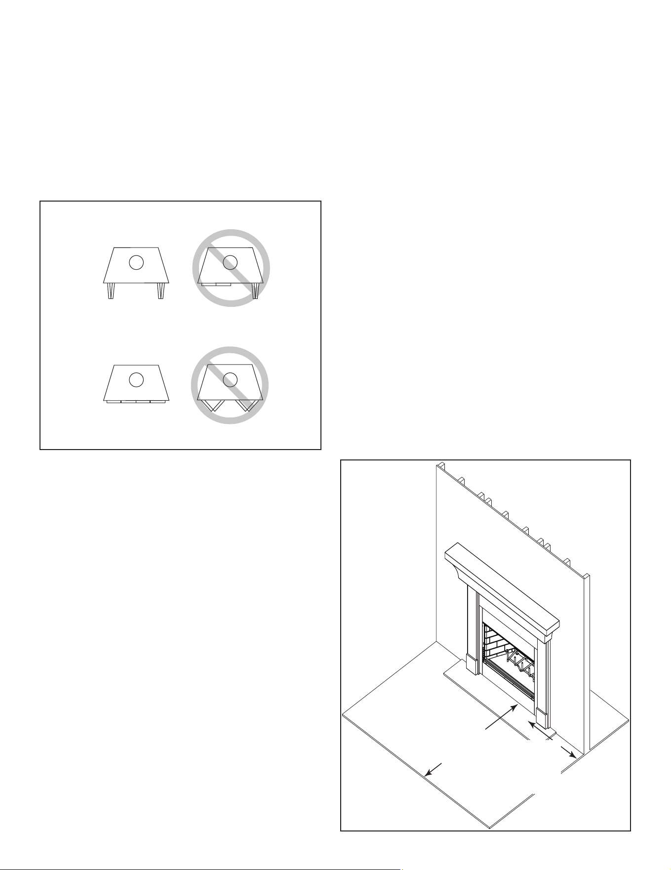
Figure 2.2 Operating Positions of Bi-fold Doors
WARNING! Risk of Fire and Smoke! Fireplaces
equipped with doors should be operated only with
doors fully open or doors fully closed. If doors are left
partly open, gas and ame may be drawn out of the
replace opening.
WARNING! Risk of Fire! Install ONLY doors approved
by Hearth & Home Technologies, Inc.
• Glass doors are optional.
• Refer to Figure 2.2 for how to properly use them.
G. Glass Doors
48 in. (1219 mm)
Clear Space
Front of Fireplace
12 in. (305 mm)
Clear Space
Sides of Fireplace
(from the FP
opening)
Figure 2.3 Clear Space
I. Vented Gas Log Sets & Gas Log Lighters
• Optional
• Vented gas logs or gas log lighters can be installed in
thisreplace.Followtheinstructionsprovidedwiththe
accessory for operation.
J. Optional Components
• Other options may be available
• Consult your dealer/distributor
K. Clear Space
• Do not place combustible objects within areas indicated
inFigure2.3.
WARNING! DO NOT place combustible objects in front
of the replace. High temperatures may ignite clothing,
furniture or draperies.
• Mantel - avoid placing candles and other heat-sensitive
objects on mantel or hearth. Heat may damage these
objects.
WARNING! Risk of Fire or Asphyxiation!
• DO NOT install unvented gas logs.
• Gas ame may generate fumes.
WARNING! Risk of Fire! DO NOT install and or use
any component not approved by Hearth & Home Tech-
nologies Inc.
Thecoolingairkitissuppliedasastandardfeaturewith
thisreplaceandisrequiredforsafeoperation.Installation
must be done at the time of initial construction. The cool-
ingairinlettubesmustbeaminimumof12in..(305mm)
abovethebaseofthereplacetopreventpotentialblock-
agebysnoworyarddebris.Seepage14.
H. Dual Cooling Air Kit (REQUIRED)
Outdoor Lifestyles by Hearth & Home Technologies • ODVILLA Wood Owners/Install • 4072-345 Rev B • 05/23

10
L. Wood Fuel
Hardwood vs Softwood
Yourreplaceperformancedependsonthequalityofthe
rewoodyouuse.
• Seasonedwoodcontainsabout8,000BTUsperpound
.
• Hard woods are more dense than soft woods.
• Hardwoodscontain60%moreBTUsthansoftwoods.
• Hard woods require more time to season, burn slower
and are harder to ignite.
• Soft woods require less time to dry, burn faster and are
easier to ignite.
• Starttherewithsoftwoodtobringthereplaceupto
operating temperature and to establish draft.
• Add hard wood for slow, even heat and longer burn
time.
Themajorityoftheproblemsreplaceownersexperience
are caused by trying to burn wet, unseasoned wood.
• Wet, unseasoned wood requires energy to evaporate
the water instead of heating your home, and
• Evaporating moisture cools your chimney, accelerating
formation of creosote.
WARNING! Risk of Fire!
• DO NOT burn wet or green wood.
• Wet, unseasoned wood can cause accumulation of
creosote.
Moisture
Soft woods Hard woods
• DouglasFir • Oak
• Pine • Maple
• Spruce • Apple
• Cedar • Birch
• Poplar
• Aspen
• Alder
Storing Wood
Steps to ensure properly seasoned wood:
• Stackwoodtoallowairtocirculatefreelyaroundand
through woodpile.
• Elevate wood pile o ground to allow air circulation
underneath.
• Smallerpiecesofwooddryfaster.Anypieceover6in.
(152 mm) in diameter should be split.
• Wood(wholeorsplit)shouldbestackedsobothends
of each peice are exposed to air. More drying occurs
through the cut ends than the sides.
• Store wood under cover to prevent water absorption
from rain or snow. Avoid covering the sides and ends
completely.
Seasoned Wood
• Cut logs to size
• Splitto6in.(152mm)orless
• Airdrytoamoisturecontentofaround20%
- Soft wood - about nine months
- Hard wood - about eighteen months
NOTICE: Seasoning time may vary depending on drying
conditions.
WARNING! Fire Risk! DO NOT store wood:
• In front of the replace.
• In space required for loading or ash removal.
Processed Solid Fuel Firelogs
Manufacturedrelogsmaybeusedwiththisreplace.
Hearth & Home Technologies Inc. recommends the use of
ULClassiedprocessedfuelrelogs.Followthemanufac-
turer’slightingandsafetyinstructions.
Usingrelogsmayrequiremorefrequentchimneyinspec-
tion and cleaning.
Donotpokeorstirthelogswhiletheyareburning.Use
onlyrelogsthathavebeenevaluatedfortheapplication
inmanufacturedreplacesandrefertorelogwarnings
andcautionmarkingsonpackagingpriortouse.
Outdoor Lifestyles by Hearth & Home Technologies • ODVILLA Wood Owners/Install • 4072-345 Rev B • 05/23
11
3 3
Maintenance and Service
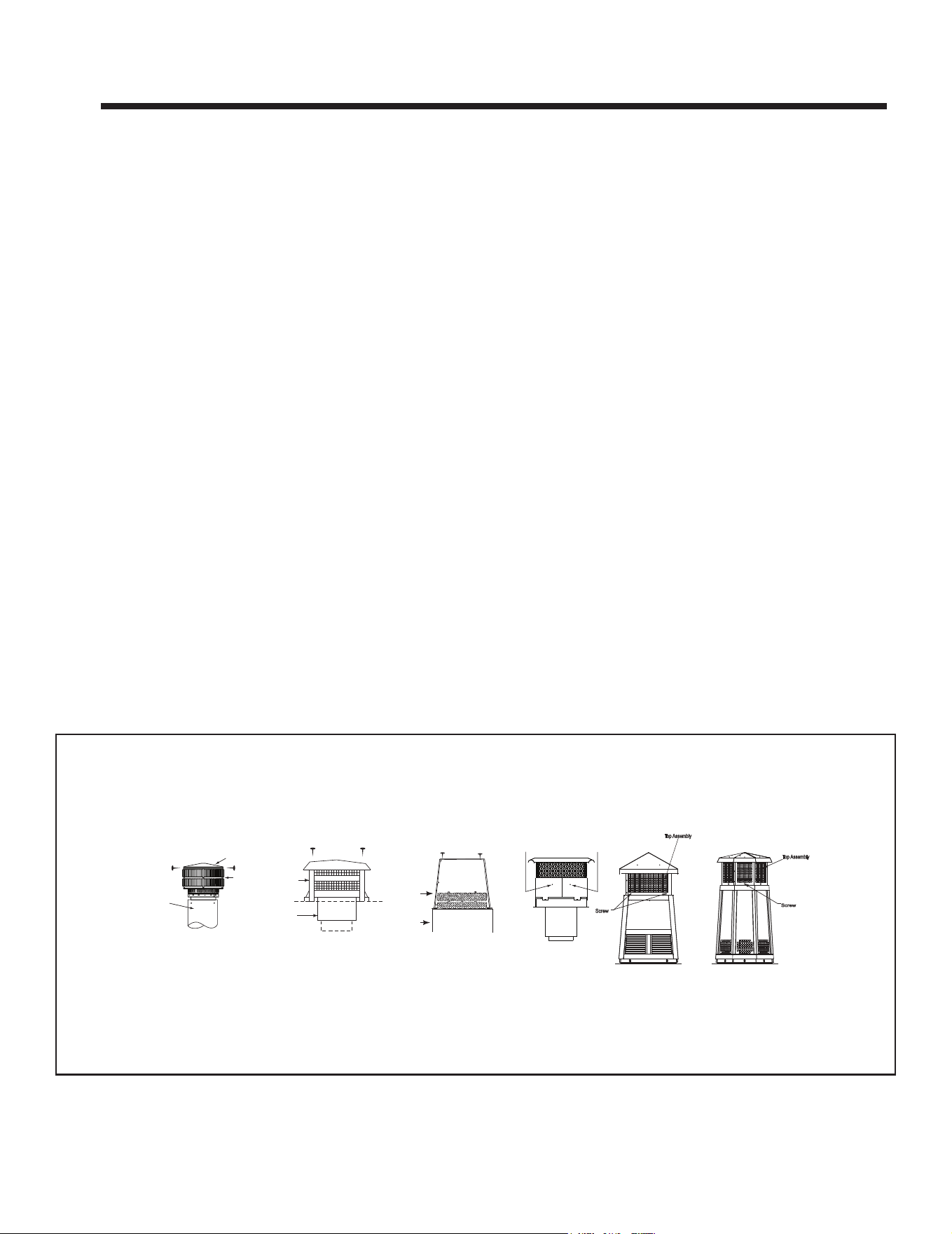
Figure 3.1 Chimney & Termination Cap Cleaning
A. Disposal of Ashes
Frequency: When they reach bottom of grate
By: Homeowner
WARNING! Risk of Fire! Ashes could contain hot em-
bers.
• Placeashesinametalcontainerwithatight-ttinglid.
• The closed container should be placed on a non-
combustibleoororontheground,wellawayfromall
combustiblematerials,pendingnaldisposal.
• If the ashes are disposed of by burial in soil or otherwise
locally dispersed, they should be retained in the closed
container until all cinders have thoroughly cooled.
B. Chimney Inspection/Cleaning
Frequency: At least twice a year during heating season
orasrecommendedbyacertiedchimneysweep
By: Certiedchimneysweep
WARNING! Risk of Fire! Ignited creosote is extremely
HOT. Prevent creosote buildup.
RefertoFigure3.1toremove/reinstallterminationcaps.
Creosote - Formation and Need for Removal
When wood is burned slowly, it produces tar and other
organic vapors, which combine with expelled moisture to
form creosote. The creosote vapors condense in the rela-
tivelycoolchimneyueofaslow-burningre.Asaresult,
creosoteresidueaccumulatesontheuelining.When
ignitedthiscreosotemakesanextremelyhotre.
WARNING! Risk of Fire! A chimney re can permanently
damage your chimney system and nearby structures.
Intheeventofachimneyre,Hearth&HomeTechnolo-
gies Inc. recommends:
• replacement of the chimney, and
• inspection of the adjacent structure to the provisions of
NFPA Level III inspection criteria.
The chimney shall be inspected at least twice a year during
the heating season to determine when a creosote buildup
has occurred.
When creosote has accumulated it shall be removed to re-
ducetheriskofachimneyre.
Outdoor Lifestyles by Hearth & Home Technologies • ODVILLA Wood Owners/Install • 4072-345 Rev B • 05/23
Chimney
Remove 4 screws
and lift top pan off.
Cap
Slip
Section
ST375
Square
Termination Cap
Cap
Remove screws,
lift top cover.
Top Cover
TR344/TR342
Round
Termination Cap
Chase
Cap
1. Remove the 4 screws.
2. Remove the screen.
3. Remove the baffle.
TS345/TS345P
Square
Termination Caps
TCT375
Terra Cotta
Termination Cap
Remove 2 screws from
the front and back and
lift the top off.
DT SERIES
2. Lift Top off
1.
Remove (8) screws

12
C. Check Firebox Refractory
Frequency: After each ash removal
By: Homeowner
D. Inspect Grate
Frequency: After each ash removal
By: Homeowner
Inspect grate for:
• Warpingorsagging1-1/2in.(38mm)ormore
• Brokenwelds
• Burn-through of grate bars
For safe operation, replace only with an approved grate
from Hearth & Homes Technologies Inc.
WARNING! Risk of Fire! Inspect replace refractory.
Crumbling, deteriorated refractory can allow overheating
of surrounding materials.
Expansionandcontractionwillcauseminorcrackingof
the refractory. This is normal. The refractory will require
periodic replacement depending on use.
The panels should be replaced if
• Cracksexceed¼inch(6mm)inwidth,
• Metal is exposed behind the refractory,
• Large pieces of refractory fall out.
E. Glass Cleaning
Frequency: As desired
By: Homeowner
Clean glass with a non-abrasive commercially available
cleaner or ashes:
• Light deposits
- Use household glass cleaner
• Heavy deposits
- Use wood ash on damp cloth or,
- Usecommercialreplaceglasscleaner(consultwith
your dealer)
CAUTION! Handle glass assembly with care. Glass is
breakable.
• Avoid striking, scratching or slamming glass
• Avoid abrasive cleaners
• DO NOT clean glass while it is hot
Outdoor Lifestyles by Hearth & Home Technologies • ODVILLA Wood Owners/Install • 4072-345 Rev B • 05/23
13
4 4
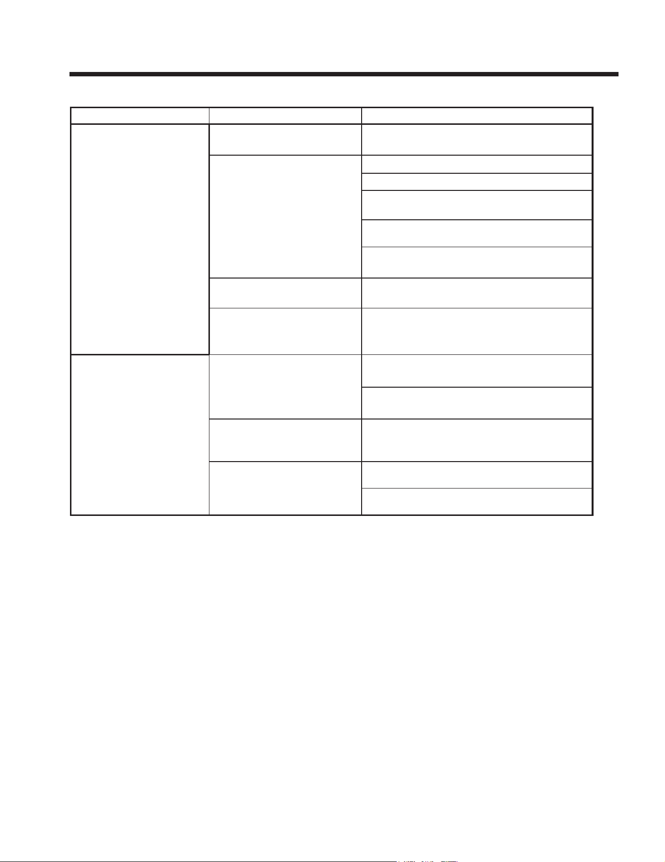
Troubleshooting Guide
Start Fire Problems Possible Cause Solution
Can’tgetrestarted
Excessivesmokeorspillage
Burns too slowly
Smolders, sizzles
Notenoughkindling/paperorno
kindling/paper
Usedrykindling,morepaper.Arrangekindling&
wood for air movement.
Notenoughairforretoignite Checkforrestrictedcap/shroud.
Checkforueblockage.
Pre-warmuebeforestartingre
Checkforadequateventheight(refertochimney
assembly section).
Wood condition is too wet, too
large
Use dry, seasoned wood
Bed of coals not established
before adding wood
Startwithpaper&kindlingtoestablishbedof
coals(refertostartingresection).
Flueblockagesuchasbirds’nests
or leaves in termination cap
Have chimney inspected for creosote and cleaned
byacertiedchimneysweep.
Fire burns too fast Extremely dry or soft wood Mix in hardwood.
Mixinlessseasonedwoodafterreisestablished
(refer to wood fuel section).
No glass doors Addglassdoorstoslowdownairow.
Overdrafting Checkforcorrectventheight;toomuchvertical
height creates overdrafting.
Checklocationofventtermination(referto
chimney assembly section).
Outdoor Lifestyles by Hearth & Home Technologies • ODVILLA Wood Owners/Install • 4072-345 Rev B • 05/23
14
Outdoor Lifestyles by Hearth & Home Technologies • ODVILLA Wood Owners/Install • 4072-345 Rev B • 05/23
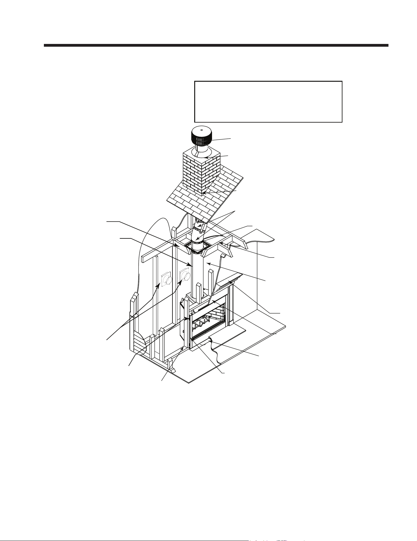
Non-combustible
roof flashing maintains
minimum clearance
around chimney
Additional lateral
support for chimney
above roof (or enclosed
in chase) if needed
(Section 8.A.)
Ceiling firestop
on floor of attic
(Section 8.E.)
Support straps
on rafter support
chimney (not shown)
Termination cap
(Section 8.I. & 9.D.)
Chimney penetrates roof
preferably without affecting
roof rafters (Section 8.F.)
Offset & Return (with hanger straps)
(Section 8.B.)
Framing headed off
in ceiling joists
(Section 8.D.)
Enclosed space above
and around fireplace
(Section 6.B.)
Mantel and surround
(Section 11.E. & 11.F.)
Decorative facing
and trim
(Section 11.D.)
Hearth extension
(Section 11.C.)
Factory-built fireplace
Protective metal
hearth strip(s)
(Section 7.B.)
Combustible framing/header
on top of V-shaped standoffs
(Section 6.D.)
Chimney system
(Section 8)
Attic insulation shield (not shown)
must be used here to keep
insulation away from chimney
if attic is insulated (Section 8.E.)
Storm Collar
(Section 9.D.)
NOTICE:
• Illustrations and photos reflect typical installations
and are for design purposes only.
• Illustrations/diagrams are not drawn to scale.
• Actual product may vary from pictures in manual.
Cooling air kit- Outlet
must be no less than
12 inches off ground
level
Installer Guide
5 5
Getting Started
A. Typical Fireplace System

15
Before beginning the installation be sure the following
tools and building supplies are available:
Reciprocating saw Framing material
Pliers Non-combustible sealant
Hammer Gloves
Phillips screwdriver Framing square
Flat blade screwdriver Electric drill and bits
Plumb line Safety glasses
Level Tape measure
1/2-3/4in.length,#6or#8self-drillingscrews
Misc. screws and nails
D. Tools and Supplies Needed
F. Inspect Fireplace and Components
WARNING! Risk of Fire and/or Explosion! Damaged
parts could impair safe operation. DO NOT install dam-
aged, incomplete or substitute components. Keep re-
place dry.
• Removereplaceandcomponentsfrompackagingand
inspect for damage.
• Vent system components and doors are shipped in
separatepackages.
• Report to your dealer any parts damaged in shipment.
• Read all the instructions before starting the
installation. Follow these instructions carefully
during the installation to ensure maximum safety
and benet.
E. Fireplace System Requirements
Thisreplacesystemrequires:
• Fireplace
• Hearth Refractory
• Grate Assembly
• Hearth Extension (required, sold separately)
• Chimney System (required, sold separately)
• Termination Cap (required, sold separately)
• Drain Pan (recommended on wood surfaces, sold
separately)
Outdoor Lifestyles by Hearth & Home Technologies • ODVILLA Wood Owners/Install • 4072-345 Rev B • 05/23
B. Design and Installation Considerations
NOTICE: Check building codes prior to installation.
• Installation MUST comply with local, regional, state and
national codes and regulations.
• Consultinsurancecarrier,localbuilding inspector,re
ocialsorauthoritieshavingjurisdictionoverrestrictions,
installation inspection and permits.
Before installing, determine the following:
• Wherethereplaceistobeinstalled
• Theventsystemcongurationtobeused
• Gas supply piping
• Framingandnishingdetails
• Whether optional accessories are desired
Thisoutdoorreplacewillshedmoderateamountsofwa-
ter, but is not waterproof. Water and condensing water va-
por may enter the chase under certain conditions.
The replace will not perform as an exterior wall. Mois-
ture penetration must be considered for construction that
placesthereplaceinstructurewallsoronmoisturesensi-
tive surfaces.
When installed on exterior walls: Hearth & Home Tech-
nologies recommends that the replace chase be con-
structedoutsidethestructure’sweatherenvelope.Where
theplatformmeetsthewall,useaashingdetailsimilarto
thatrequiredforattacheddecks.Chaseplatforms,includ-
ing hearths should slope away from the structure at 1/8
in.to1/4in.perfoot.Thereplacecanbeshimmedlevel.
When installed on surfaces where water may collect
or cause damage: Hearth & Home Technologies recom-
mends that a drainage pan (sold separately), be placed
under the unit. This can be constructed of metal, adhe-
sive polymer membrane (such as ice and water shield) or
other suitable materials. A means of drainage out of the
pan such as tubes or weep holes should be provided. A
slopeof1/8in.to1/4in.perfoottowardsthedrainportis
suggested.Thereplacecanbeshimmedlevel.
Hearthsshouldslopeawayfromthefrontofthereplace
andchaseat1/8in.to1/4in.perfoot.Sparkstripsmust
be on top of any combustible hearth materials used for
moisture management.
C. Moisture Resistance:
16
6 6
Framing & Clearances
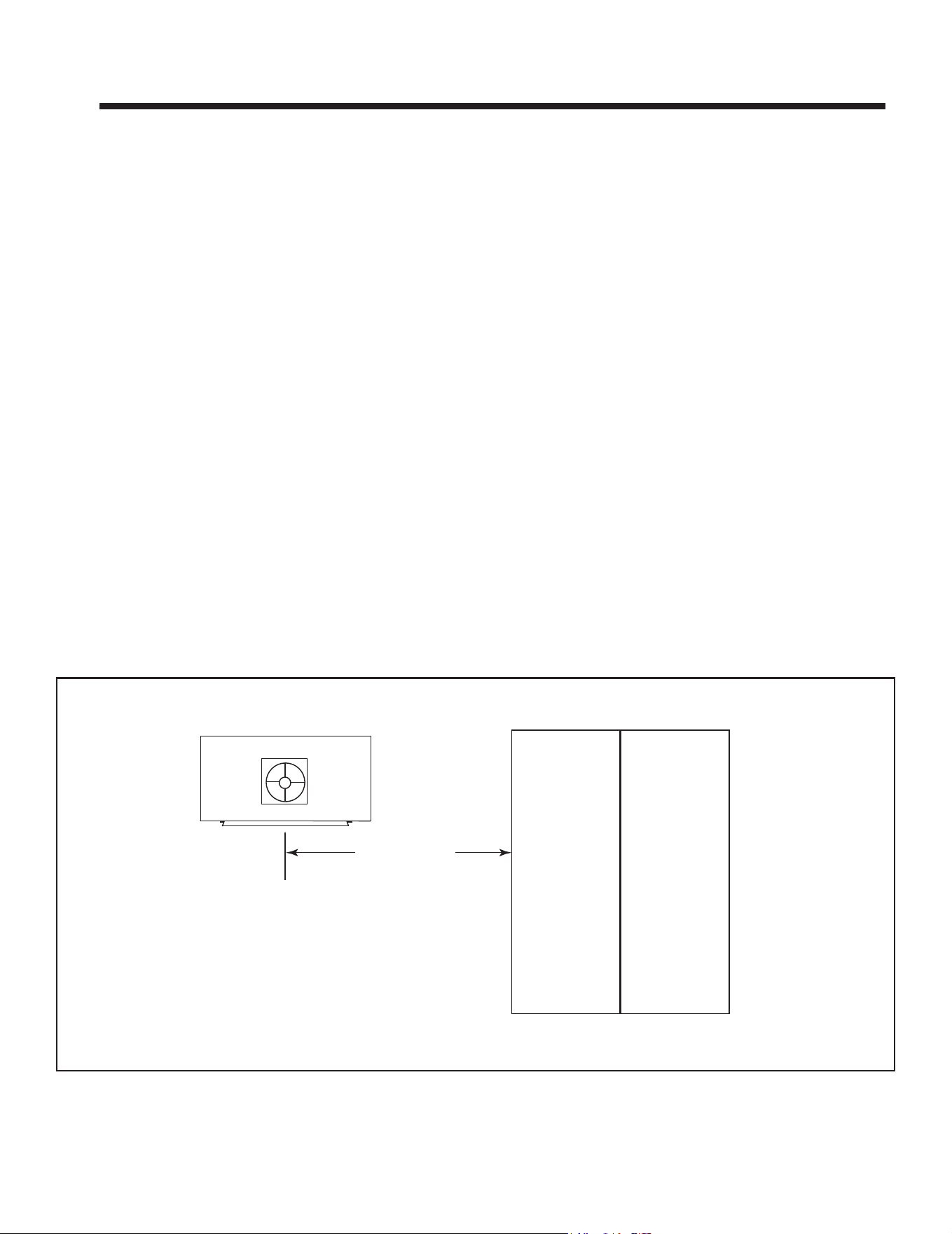
Figure 6.1 Freestanding Installation
A. Selecting Fireplace Location
Thisoutdoorreplacewillshedmoderateamountsof
water, but is not waterproof. Water and condensing water
vapor may enter the chase under certain conditions.
Thereplacewillnotperformasanexteriorwall.Mois-
ture penetration must be considered for construction that
placesthereplaceagainststructurewallsoronmoisture
sensitive surfaces.
• Exterior Walls (see Figure 6.1)
Hearth & Home Technologies recommends that the
replacechase be constructed outside thestructure’s
weather envelope. Where the platform meets the wall,
useaashingdetailsimilartothatrequiredforattached
decks.Chaseplatforms,includinghearths,shouldslope
away from the structure at 1/8 in. to 1/4 in. per foot.
Thereplacecanbeshimmedlevel.Buildtheoutside
enclosure out of standard building materials, being
carefultomaintaintheminimumairclearancesspecied
in these installation instructions.
• Freestanding Installations (see Figure 6.2)
Wheninstallingthisreplaceasafreestandingreplace
on your porch, patio or in your yard, it must be enclosed
topreventimpactdamagetothereplace.
• The cooling air hoods MUST be used if installing in
a combustible enclosure.
• If unit is installed on cement and totally enclosed with non
combustible materials (i.e. metal studs, cement board,
etc.) the cooling air hoods do not need to be installed.
• When Installed on Surfaces Where Water May Collect
or Cause Damage:
Hearth & Home Technologies recommends that a
drainage pan be placed under the unit, (sold separately).
This can be constructed of metal, adhesive polymer
membrane (such as ice and water shield) or other
suitable materials. A means of drainage out of the pan
such as tubes or weep holes should be provided. A slope
of 1/8 in. to 1/4 in. per foot towards the drain port is
suggested.Thereplacecanbeshimmedlevel.Hearths
shouldslopeaway from thefrontofthe replace and
chaseat1/8in.to1/4in.perfoot.Sparkstripsmustbe
used on top of any combustible hearth materials used
for moisture management.
FREESTANDING
INSTALLATION
(Combustible Structure)
(Enclosed Fireplace)
10 ft Min.
From Termination
Outdoor Lifestyles by Hearth & Home Technologies • ODVILLA Wood Owners/Install • 4072-345 Rev B • 05/23
THERE IS NOT A FLUE DAMPER,THEREFORE
UNIT CANNOT BE INSTALLED INDOORS.
►
17
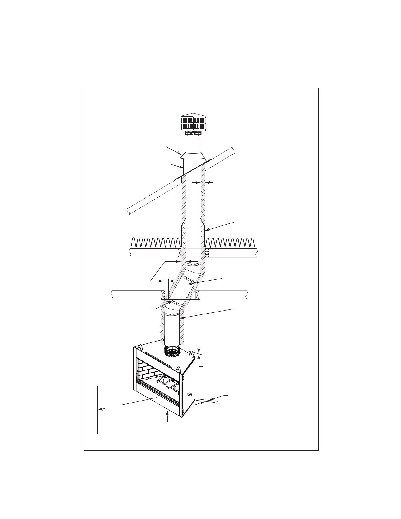
B. Clearances
WARNING! Risk of Fire! You must comply with all minimum air space clearances to combustibles as specied in Fig-
ure 6.2. DO NOT pack required air spaces with insulation or other materials.
Outdoor Lifestyles by Hearth & Home Technologies • ODVILLA Wood Owners/Install • 4072-345 Rev B • 05/23
(roof)
(insulation)
0 in. to level
of standoffs
Attic
Insulation
Shield
(ceiling)
(attic)
(ceiling)
Offset/Return (secured
with hanger straps)
Storm Collar
Roof Flashing
1/2 in. (13 mm) to back &
sides of appliance
Must have 2 in. (51 mm)
minimum clearance
to header
0 in.
to floor
2 in. (51 mm) min.
Shaded areas
represent
2 in. (51 mm) min.
air space clearance
required around pipe
Combustible Object
48 in.
1219 mm
Ceiling Firestop
Figure 6.2 Clearances to Combustible Materials
18
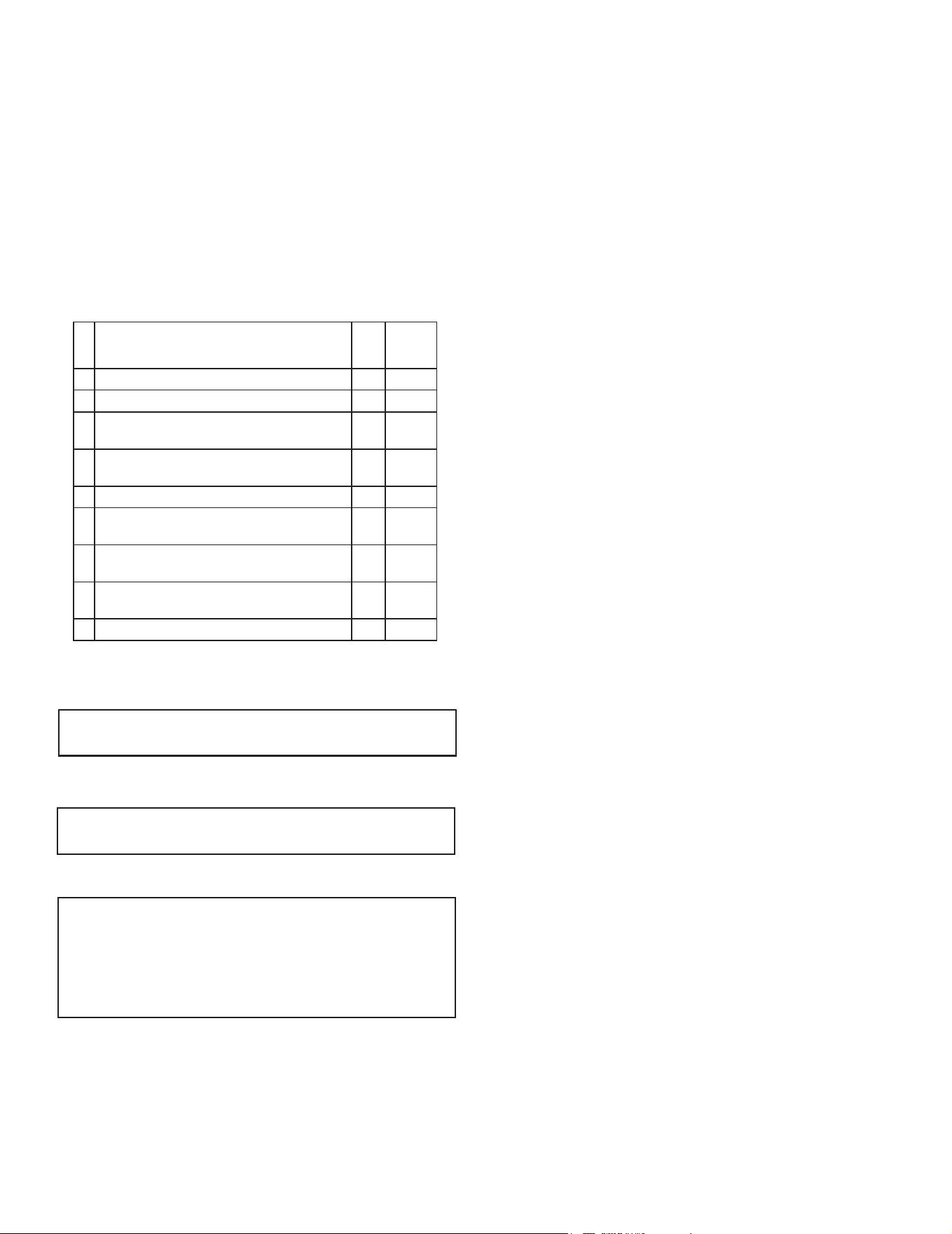
D. Frame the Fireplace
Figure6.4showstypicalframingusingcombustiblematerials(2x4lumbershown).
• ObserveallrequiredairspaceclearancestocombustiblematerialsasshowninFigure6.1&6.2.
• Framingacrossthetopofreplacemustbeabovetopstandos.
Figure 6.4 Framing the Fireplace
C. Sidewalls/Surrounds
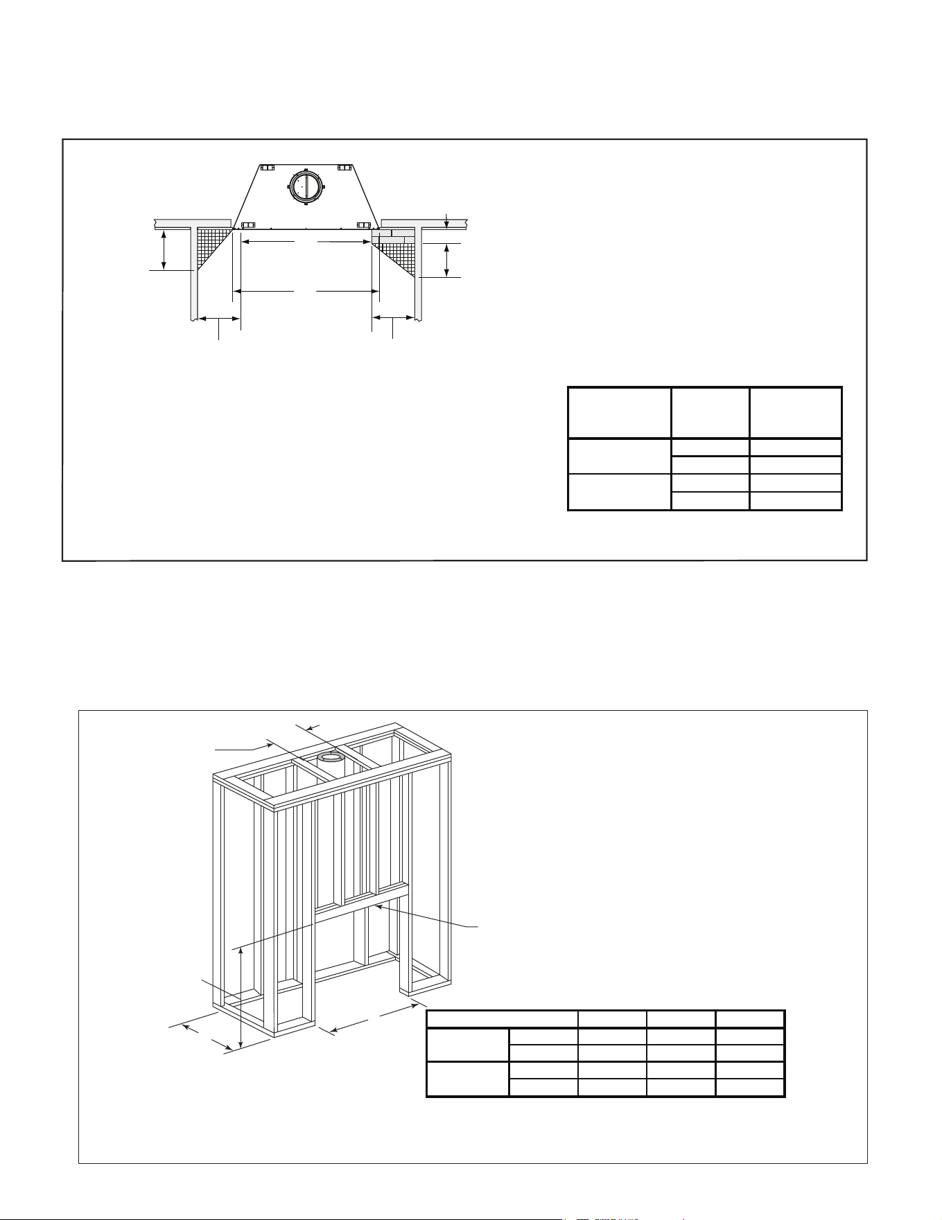
• Adjacentcombustiblesidewallsmustbelocatedaminimumof12in.(305mm)fromthereplaceopening.
• Combustible and non-combustible mantel legs, surrounds and stub walls may be constructed within the gridded area,
Figure6.3.
Figure 6.3 Mantel Leg or Wall Projections (Acceptable on both sides of opening)
B
C
A
Header MUST NOT be notched!
Model A B* C**
in. 42 21 1/2 39 3/4
mm 1067 546 1010
in. 48 21 1/2 39 3/4
mm 1219 546 1010
ODVILLA-36
ODVILLA-42
* If interior of chase will be drywalled, add the thickness to
this measurement.
** Adjust header height for a raised floor under fireplace.
14 1/2 in.
(368 mm)
framing
Model
A
Fireplace
opening
B
Outside
Dimensions
36 in. 41 in.
914 mm 1041 mm
42 in. 47 in.
1067 mm 1194 mm
ODVILLA-42
ODVILLA-36
B
A
9 3/4 in.
[248 mm]
12 in.
[305 mm]
12 in.
[305 mm]
11 1/4 in.
[286 mm]
FLUSH
FRONT
4 in.
[102 mm]
BRICK
FRONT
50° angle
39° angle
Outdoor Lifestyles by Hearth & Home Technologies • ODVILLA Wood Owners/Install • 4072-345 Rev B • 05/23
19
ft m
• Minimumheightwithoset/return 14.5 4.42
•
Maximum height 90 27.43
• Maximumchimneylengthbetweenanoset
and return
20 6.1
• Maximum distance between chimney
stabilizers
35 10.67
• Doubleoset/returnminimumheight 20 6.1
• Maximum unsupported chimney length
betweentheosetandreturn
6 1.83
• Maximum unsupported chimney height above
thereplace
35 10.67
• Minimumoverallstraightheightifreplaceis
freestanding
6.4 1.95
• Minimum Straight Height 14.5 4.42
E. Chimney Requirements
Whenplanningyourreplacelocation,thechimneycon-
struction and necessary clearances must be considered.
Thereplacesystemandchimneycomponentshavebeen
tested to provide exibility in construction. The following
gures are the minimum distances from the base of the
replace.
• Minimum overall straight height is 6 ft 4 in. If the
replaceisfreestandingandaminimumof10ftfroma
combustible structure. SeeFigure6.1
• Chimneymustextend2ft(.6m)aboveanyportionofthe
roofwithin10ft(3m)ofthechimney.RefertoFigure8.7
Note: Amaximumoftwopairsofosetsandreturnsmay
be used.
The CAK4AisrequiredforuseinCanada
NOTE: Before framing up the chase, consider where and
how the chimney will run. If there are obstacles that might
beintheway,itmaybenecessarytomakethechase
largerthanshowntoallowforosetstobeused.Refer
toosetchartabove.
Outdoor Lifestyles by Hearth & Home Technologies • ODVILLA Wood Owners/Install • 4072-345 Rev B • 05/23
►
20
7 7
Installation of Fireplace
CAUTION! Risk of Cuts/Abrasions. Wear protective
gloves and safety glasses during installation. Sheet metal
edges are sharp.
A. Position the Fireplace
• Thisreplacemaybeplacedoneitheracombustibleor
noncombustiblecontinuousatsurface.
• FollowframinginstructionsinSection6.
WARNING! Risk of Fire! Prevent contact with sag-
ging, loose insulation.
• DO NOT install against vapor barriers or exposed
insulation.
• Secure insulation and vapor barriers.
• Provide minimum air space clearances at the sides
and back of the replace assembly as outlined in
Section 6.
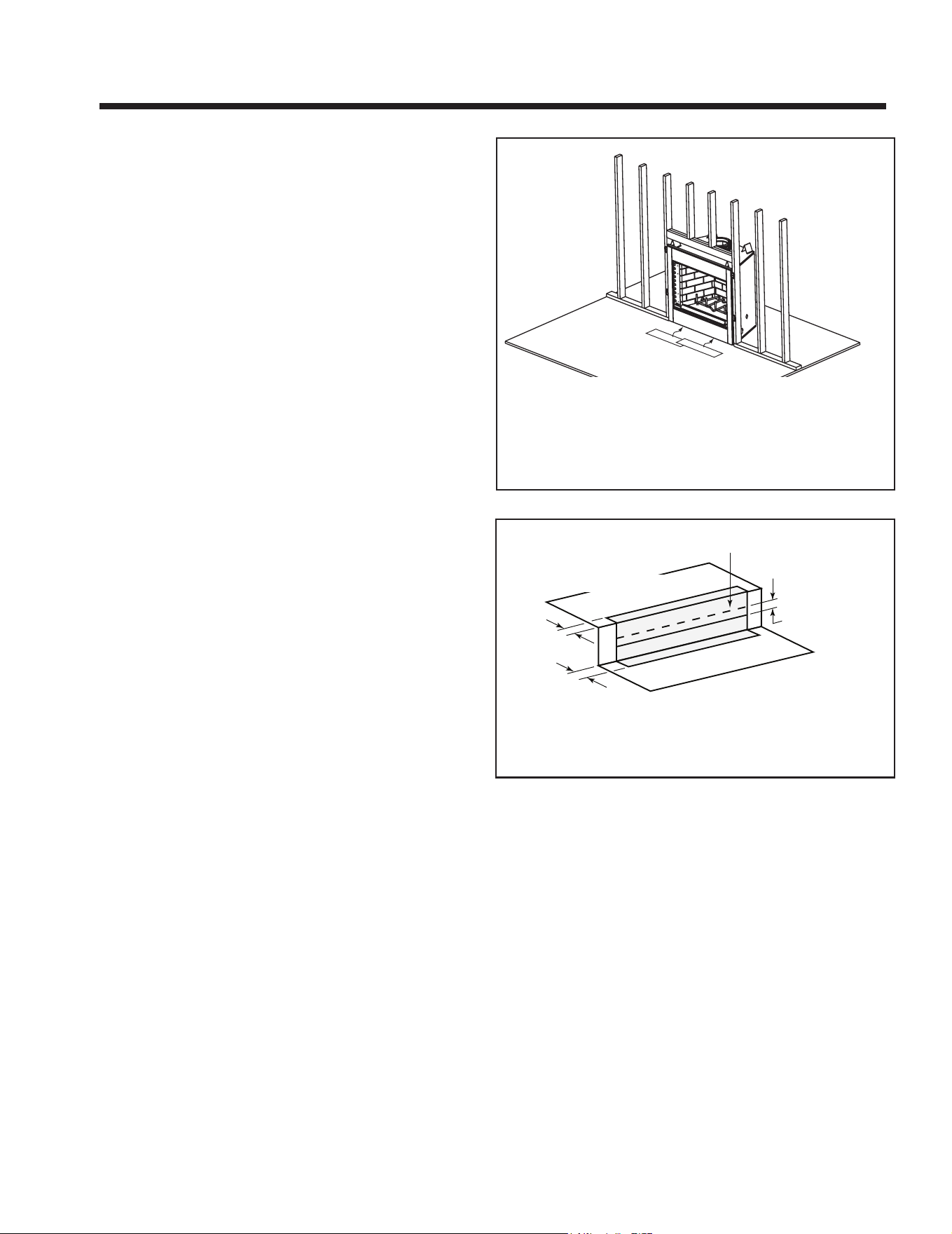
Protective metal strips are placed 2 in. (51 mm) under the
front of the fireplace and must extend beyond the front
and sides of fireplace opening by 2 in. (51 mm)
Figure 7.1 Position the Protective Metal Hearth Strips
B. Place Protective Metal Hearth Strips
WARNING! Risk of Fire! Protective metal hearth strips
MUST be installed. DO NOT cover metal strips with com-
bustible materials. Sparks or embers may ignite ooring.
• Refer to Figures 7.1 and 7.2.
• Locate the two protective metal hearth strips measuring
approximately26in.x4in.(660mmx102mm)included
withthisreplace.
• Slide each metal strip 2 in. (51 mm) under front edge of
replace.
• Overlapstripsinthemiddleofreplaceopeningby1in.
(25 mm) minimum.
• Metal strips must extend beyond the front and sides of
thereplaceopeningbyatleast2in.(51mm).
• Protect the front of a platform elevated above the hearth
extensionwithmetalstrips(notincludedwithreplace)
per Figure 7.2. See Section 11 for hearth extension
instructions.
C. Level Fireplace
• Levelreplaceside-to-sideandfront-to-back.
• Shim with non-combustible material as necessary.
• Securereplacetoframingwithnailingangeswitha
minimumoftwofastenerspernailingange.
• Checkreplaceopeningforsquaretoensurepropert
ofglassdoors.Measurediagonalsofreplaceopening
tomakesuretheyareequal.
Raised Platform
Floor
2 in.
(51 mm)
1 in. (25 mm) min.
overlap
2 in.
(51 mm)
Top piece must overlap
bottom piece
Figure 7.2 Protect the Front of an Elevated Platform
Outdoor Lifestyles by Hearth & Home Technologies • ODVILLA Wood Owners/Install • 4072-345 Rev B • 05/23
21
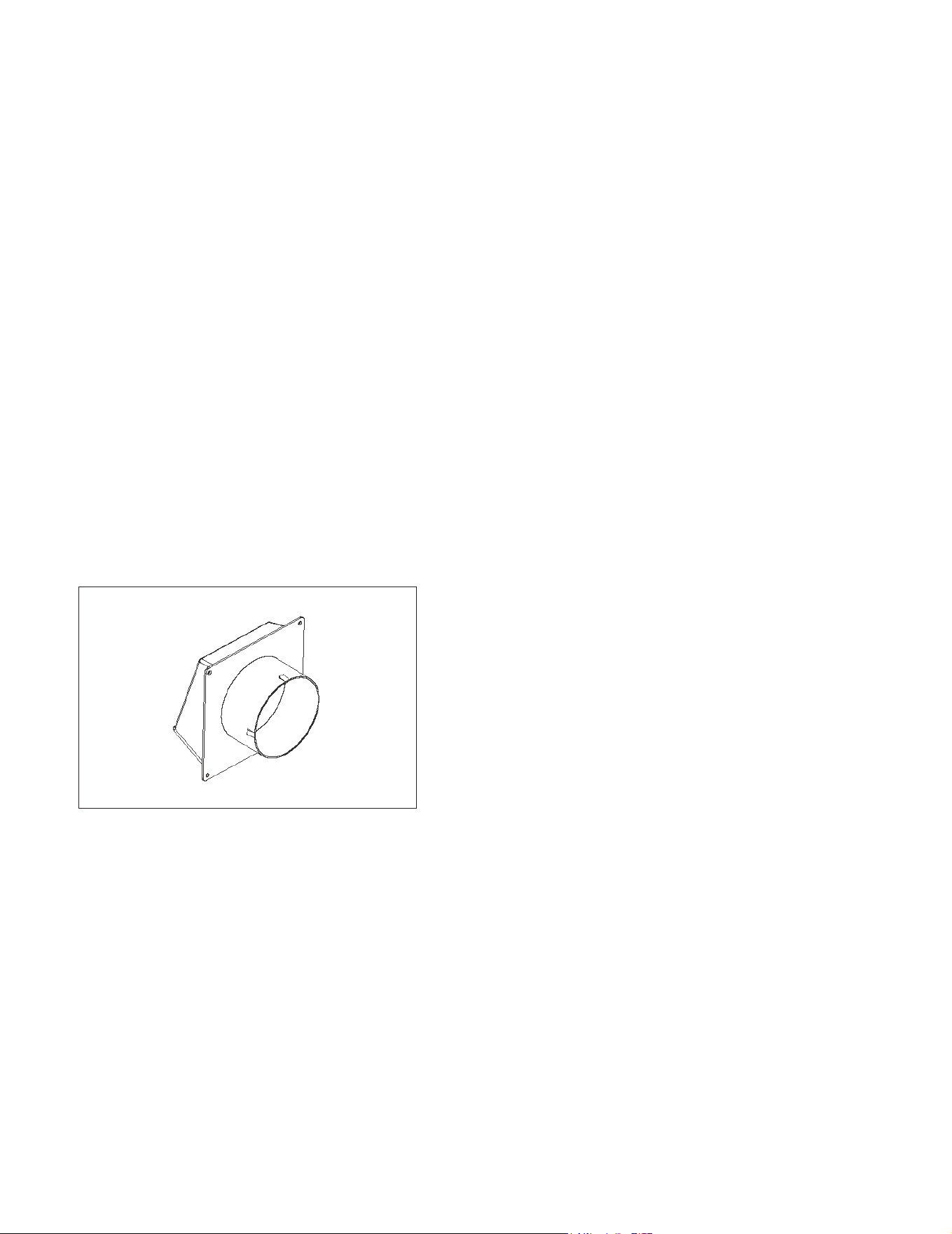
WARNING! Cooling air must be provided when install-
ing in combustible enclosure or on combustible surface.
• Locatecoolingairhoodstopreventblockagefrom
leaves,snow/ice,orotherdebris.Blockagescould
cause the unit to overheat.
• The lowest point of the cooling air hoods to be located
a minimum of 12” above the bottom of unit.
• Do Not place cooling air hood close to exhaust vent.
• Cuta4in.holeintheenclosureforthehood.
• The outside air hood can be painted to match/accent
the color of the structure.
• An air grille can be used in place of the plastic hoods
(Provided); Grill MUST have a minimum of 25 sq/
inopeningtoallowforpropercoolingairowtounit.
Lowest edge of grille to be located a minimum of 12”
above the bottom of the unit
Caution! Risk of Fire or Asphyxiation! Do not draw
outsideairfromwall,oor,orceilingcavity,orenclosed
spaces such as an attic or garage.
D. Install Cooling Air Hoods (PROVIDED)
Outdoor Lifestyles by Hearth & Home Technologies • ODVILLA Wood Owners/Install • 4072-345 Rev B • 05/23
Figure 7.3 Cooling Air Hood
22
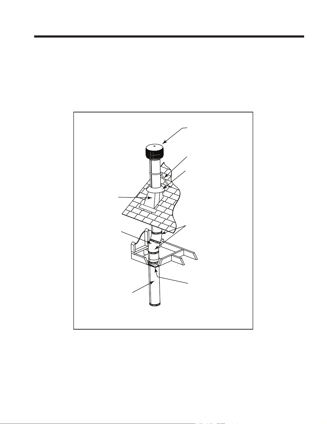
Chimney must extend
beyond combustible
roof structure
Maintain minimum
height of chimney
above roof
Additional
support for
tall chimneys
Install roof flashing
according to minimum
requirements
Maintain minimum
clearances to
combustibles as
specified
Offsets/returns
may not exceed
30° from vertical
Lock chimney
sections together
firmly to resist
movement
Ceiling firestops
are required where
chimney passes
through ceiling or
floor
Support straps for returns
must be secured to
adequate framing
Termination Cap
Storm Collar
Offsets and returns must
be secured with the screws
provided (outer pipe only)
The chimney must be
enclosed from the
fireplace to the attic
maintaining the 2 inch
clearances.
Figure 8.1 Typical Chimney System - Guidelines for Chimney System Installation
8 8
Chimney Assembly
NOTICE: Chimney performance may vary.
• Trees, buildings, roof lines and wind conditions aect
performance.
• Chimney height may need adjustment if smoking or
overdraft occurs.
Outdoor Lifestyles by Hearth & Home Technologies • ODVILLA Wood Owners/Install • 4072-345 Rev B • 05/23
23
20 ft (6.10 m) max.
pipe between an
offset & return
Ceiling Firestop
35 ft (10.67 m)
max. straight
unsupported
chimney height
14.5 ft (4.42 m) min. height/single offset-return
20 ft. (6.1 m) min. height/double offset-return
90 ft (27.43 m) max. height
6 ft (1.83 m) max.
unsupported chimney
above roof
39 1/2 in. (1003 mm)
Effective Height
Figure 8.2 Chimney Requirements
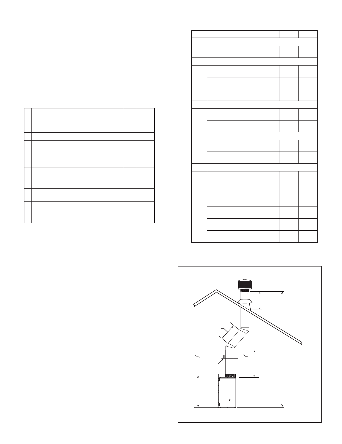
Determine the chimney components needed to complete
your particular installation:
• Measure the total vertical height of the fireplace
installationfromthebaseofthereplaceassemblyto
the approximate location of the bottom of the termination
cap.
• Subtracttheeectiveheightofthereplaceassembly
(see Figure 8.2) from the total vertical height to determine
the overall height of the chimney installation.
• Create a schematic for your application similar to Figure
8.2 showing components required (referring to Table
8.1).Figure8.1identiesthosecomponentsandwhere
used.
• Installaceilingrestopwheneverthechimneypenetrates
aoor/ceiling.
NOTICE: A maximum of two pairs of osets and returns
may be used.
CAUTION! Risk of Fire and/or Asphyxiation! DO
NOT connect this replace to a chimney ue servicing
another appliance. DO NOT connect to any air distribu-
tion duct or system. These actions could cause over-
heating/re in the chimney ue, or release of exhaust
fumes into the living areas.
ft m
• Minimumheightwithoset/return 14.5 4.42
•
Maximum height 90 27.43
• Maximumchimneylengthbetweenanoset
and return
20 6.1
• Maximum distance between chimney
stabilizers
35 10.67
• Doubleoset/returnminimumheight 20 6.1
• Maximum unsupported chimney length
betweentheosetandreturn
6 1.83
• Maximum unsupported chimney height above
thereplace
35 10.67
• Minimumoverallstraightheightifreplaceis
freestanding
6.4 1.95
• Minimum Straight Height 14.5 4.42
A. Chimney Requirements
Whenplanning your replacelocation, thechimneycon-
struction and necessary clearances must be considered.
Thereplacesystemandchimneycomponentshavebeen
tested to provide exibility in construction. The following
gures are the minimum distances from the base of the
replace.
• Minimumoverall straight height is 6 ft 4 in. if the
replaceisfreestandingandaminimumof10ftfroma
combustible structure. SeeFigure3.2.
• Chimneymustextend2ft(.6m)aboveanyportionofthe
roofwithin10ft(3m)ofthechimney.RefertoFigure6.1.
Table 8.1
HEIGHT OF CHIMNEY COMPONENTS in. mm
Chimney Stabilizer
SL3 4-3/4 121
Ceiling Firestops
FS338 0 0
FS339 0 0
FS340 0 0
Osets/Returns
SL315 13-3/8 340
SL330 15-1/2 394
Roof Flashing
RF370 0 0
RF371 0 0
Chimney Sections*
SL306 4-3/4 121
SL312 10-3/4 273
SL318 16-3/4 425
SL324 22-3/4 578
SL336 34-3/4 883
SL348 46-3/4 1187
* Dimensions reect eective height.
Outdoor Lifestyles by Hearth & Home Technologies • ODVILLA Wood Owners/Install • 4072-345 Rev B • 05/23
►
24
Table 8.2
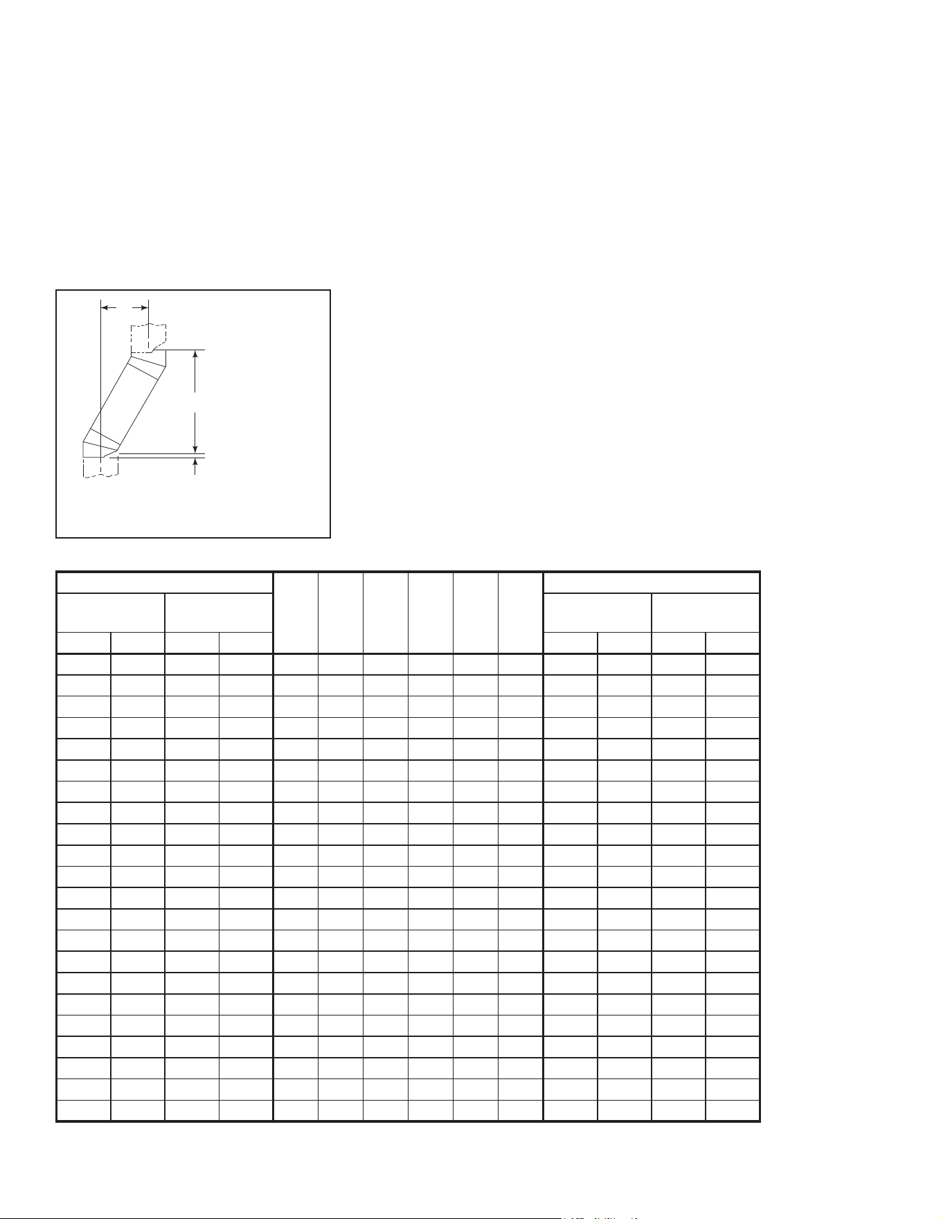
B. Using Osets/Returns
• Useanoset/returntobypassoverheadobstructions.
• Anosetandreturncanbeusedasasingleentityorseparatedbychimneysection(s).
WARNING! Risk of Fire! DO NOT use oset/returns greater than 30°. Chimney draft will be restricted and could cause
overheating and re.
• Measuretheshiftneededtoavoidtheoverheadobstruction.RefertodimensionAinFigure8.3.
• Find the appropriate A dimension listed in Table 8.2.
• The B dimension coinciding with the A dimension measurement in Table 8.2 represents the required vertical clearance
neededtocompletetheoset/return.
• Readacrossthecharttondthenumberofchimneysections/modelnumbersneededbetweentheosetandreturn.
A
B
1-1/4 in. (32 mm)
OVERLAP
Figure 8.3 Chimney Oset/Return
Outdoor Lifestyles by Hearth & Home Technologies • ODVILLA Wood Owners/Install • 4072-345 Rev B • 05/23
15-degree
SL306 SL312 SL318 SL324 SL336 SL348
30-degree
A
Oset
B
Height
A
Oset
B
Height
in. mm in. mm in. mm in. mm
1-5/8 41 13-3/8 340 - - - - - - 3-5/8 92 15-1/2 394
2-7/8 73 17-3/4 451 1 - - - - - 5-1/2 140 18-5/8 473
4-1/8 102 22-3/8 568 2 - - - - - 7-1/4 184 21-3/4 552
4-1/2 114 23-5/8 600 - 1 - - - - 8-1/2 216 23-3/4 603
5-3/4 146 28-1/4 718 1 1 - - - - 10-1/4 260 27 686
6 152 29-3/8 746 - - 1 - - - 11-1/2 292 29 737
7-1/4 184 34 864 - 2 - - - - 13-1/4 337 32-1/8 816
7-3/4 197 36-1/8 918 - - - 1 - - 14-1/2 368 34-1/8 867
8-3/4 222 39-3/4 1010 1 - - 1 - - 16-1/4 413 37-3/8 949
10-3/8 264 45-5/8 1159 - - 2 - - - 19-1/4 489 42-1/2 1080
10-5/8 270 46-3/4 1187 - - - - 1 - 20-1/2 521 44-5/8 1133
11-7/8 302 51-3/8 1305 1 - - - 1 - 22-1/4 565 47-3/4 1213
13-1/2 243 57-1/4 1454 - - - 2 - - 25-1/4 641 52-7/8 1343
13-3/4 349 58-3/8 1483 - - - - - 1 26-1/2 673 55 1397
15 381 63 1600 1 - - - - 1 28-1/4 718 58-1/8 1476
16-1/2 419 68-3/4 1746 - 1 - - - 1 31-1/4 794 63-1/4 1607
18 457 74-5/8 1895 - - 1 - - 1 34-1/4 870 68-1/2 1740
19-5/8 498 80-3/8 2042 - - - 1 - 1 37-1/4 946 73-3/4 1873
20-5/8 524 84-1/8 2137 1 - - 1 - 1 39-1/8 994 76-7/8 1953
22-3/4 578 91-7/8 2334 - - - - 1 1 43-1/4 1099 84-1/8 2137
24 610 96-1/2 2451 1 - - - 1 1 45-1/8 1146 87-1/4 2216
25-7/8 657 103-1/2 2629 - - - - - 2 49-1/4 1251 94-1/2 2400
Properassemblyofair-cooledchimneypartsresultinanoverlapatchimneyjointsof1-1/4in.(32mm).Eectivelengthisbuilt
into this chart.
Example:
Your“A”dimensionfromFigure8.3is141/2in.(368
mm). Using Table 8.2 the dimension closest to, but
notlessthan141/2in.(368mm)is141/2in.(368
mm)usinga30°oset/return.
Youdeterminefromthetablethatyouneed341/8in.
(867mm)(Dimension“B”)betweentheosetand
return.
Thechimneycomponentthatbesttsyourapplica-
tionisoneSL324.
25
Figure 8.4 Assembling Chimney Sections
• Supportthepipeduringconstructionandchecktobe
sure inadvertent loading has not dislodged the chimney
sectionfromthereplaceoratanychimneyjoint.
• Attachastraightchimneysectionoranosettothetop
ofthereplace.
• Placeinneruetotheinsideofthechimneysectionbelow
it. Place the outer casing outside the outer casing of the
chimneysectionbelowit.RefertoFigure8.4.
NOTICE: Chimney sections cannot be disassembled
once locked together. Plan ahead!
• Lockchimneysectionsand/orosets/returnstogetherby
pushing downward until the top section meets the stop
bead on the lower section.
• Pullonthetopsectiontomakesureitisfullyengaged
and will not separate.
• Youmayuse#6or#8sheetmetalscrewsnolongerthan
1/2in.(13mm)tofastenchimneysectionstogether.Do
NOTpenetrateinnerue.
WARNING! Risk of Fire! You MUST use screws (pro-
vided) to fasten oset/returns to chimney sections to
keep the chimney parts from twisting. Failure to do so
could cause re.
• Fasten oset/returns to chimney sections. Insert the
screws (provided) through the predrilled holes. Do NOT
penetrateinnerue.
• Secure chimney returns with hanger straps provided;
fasten to studs or joists.
• Vertical straight runs of chimney must be supported every
35ft(10.7m).
C. Assemble Chimney Sections
WARNING! Risk of Fire! DO NOT install substitute or
damaged chimney components.
• Use only those components described in this manual.
Substitute or damaged chimney components could impair
safe operation and cause overheating and re.
ROOM ABOVE (non-insulated ceiling)
ATTIC ABOVE (insulated ceiling)
B
A
Ceilng firestop from
bottom
Ceiling firestop from
top
Note:
Use same dimensional lumber for framing
ceiling firestop and joists.
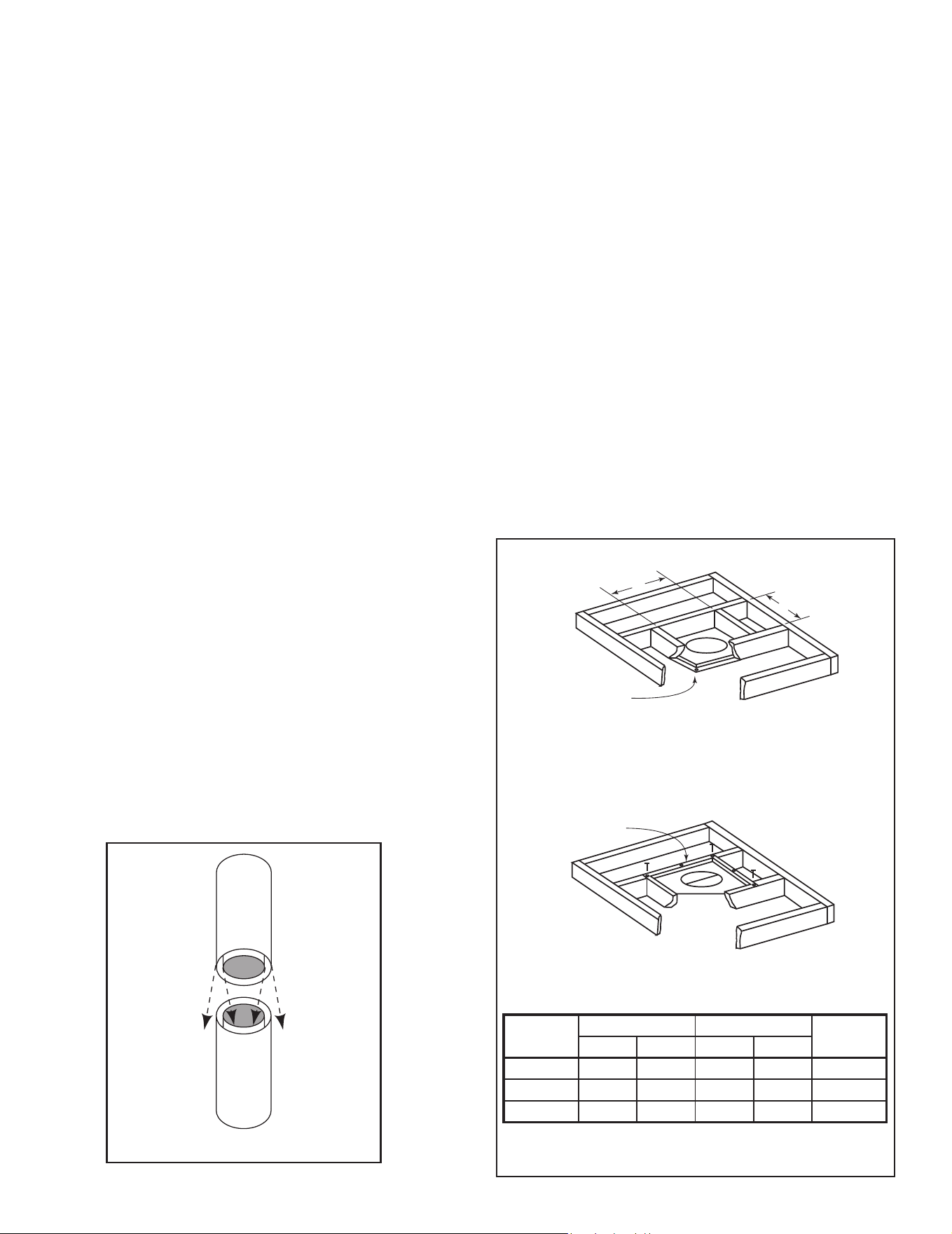
Figure 8.5 Installing the Ceiling Firestop
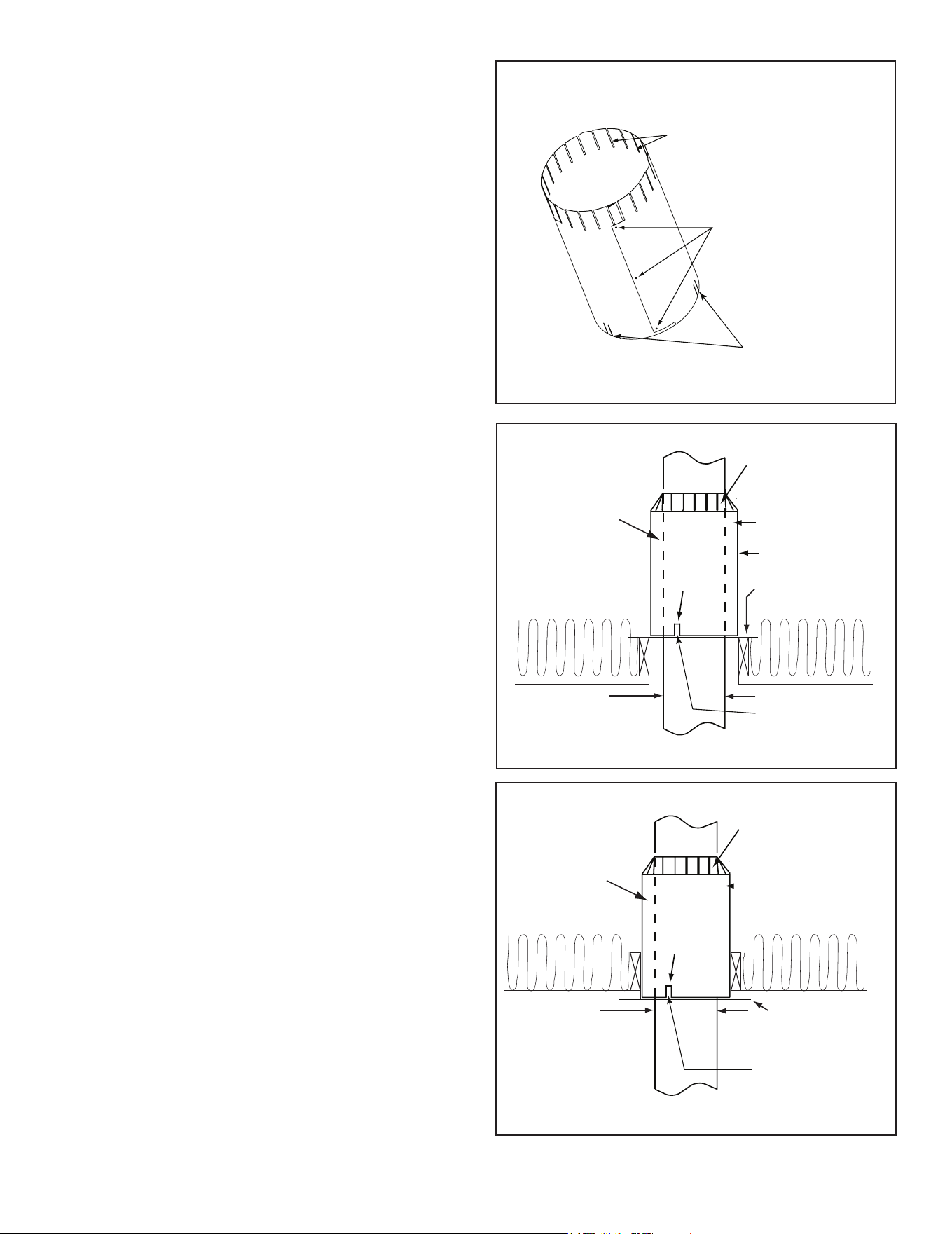
• Installaceilingrestopwheneverchimneypenetrates
ceiling/oor.
• Mark and cut an opening in ceiling as shown in
Figure 8.5.
• Frame the opening with the same size lumber used in
the ceiling joists.
• Nailtheceilingrestoptothebottomoftheceilingjoists
when there is a room above.
• Use an attic insulation shield if the ceiling is insulated.
Theceilingrestopmaythenbeattachedaboveorbelow
the joists.
D. Install Ceiling Firestops
CAUTION! Risk of Fire! Ceiling restops must be used
whenever the chimney penetrates a ceiling/oor.
• Chase construction requires ceiling restops at each
oor or every 10 ft (3.05 m) of clear space.
• The ceiling restop slows spread of re and reduces cold
air inltration.
WARNING! Risk of Fire! DO NOT seal area between
restop opening and chimney pipe except where they
enter the attic or leave the warm air envelope of the
home (use 600° F sealant).
Outdoor Lifestyles by Hearth & Home Technologies • ODVILLA Wood Owners/Install • 4072-345 Rev B • 05/23
Catalog #
A B
Anglein. mm in. mm
FS338 14-1/2 368 14-1/2 368 0°
FS339 14-1/2 368 18-3/8 467 15°
FS340 14-1/2 368 23 584 30°
26
Outdoor Lifestyles by Hearth & Home Technologies • ODVILLA Wood Owners/Install • 4072-345 Rev B • 05/23
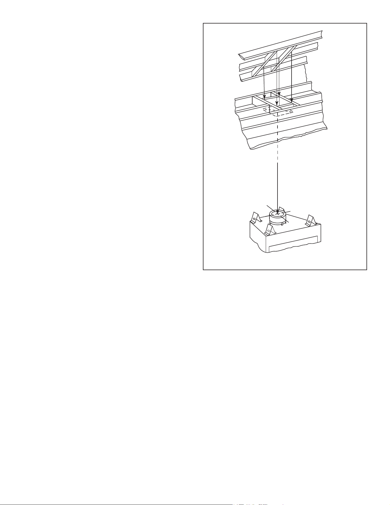
E. Installing the Attic Insulation Shield
WARNING! Risk of Fire! You MUST install an attic
installation shield when there is any possibility of insulation
or other combustible material coming into contact with the
chimney.
• DO NOT packinsulationbetweenthechimneyandthe
attic insulation shield.
• Failure to keep insulation and other materials away
fromthechimneypipecouldcauseare.
• DO NOT osetchimneyinsideinsulationshield.
• Combustible material may come into contact with
the attic insulation shield as long as the required
clearances are maintained to the chimney pipe.
Installationofaceilingrestopisrequired:
Note: In Canada a CAS8 must be installed. See instructions
providedwithkit.
• RefertoFigures8.6,8.7,and8.8.
• Iftheatticshieldispre-rolledcontinue.Ifitisaatpart,
try to roll it up to aid in wrapping it around the chimney.
• Pre-bendallthetabsinatthetopto45degrees.
• Wrap the shield (around the chimney if already
installed) until you have an overlap and the three holes
on each side match up (large holes on top).
• Insert three screws into the matching holes to form a
tube starting at the bottom.
• Bendthetabsonthebottomofthetubeinwardto90
degrees to maintain chimney air space.
• Resttheinsulationshieldontheceilingrestopbelow.
• Tapeoanyopeningsaroundthebottom.
Ifyouwanttomakeacustomshieldorbarrier,followthese
guidelines:
• Metal is preferred, although any material sti
enough to hold back the insulation can be used.
WARNING! Risk of Fire! Use of cardboard or other
materials that can deect under humidity or other
environmental conditions is not recommended.
• The shield or barrier must be tall enough to extend
above the insulation and prevent blown-in insulation
from spilling into the cavity and accommodate the
amount of insulation as required by the National
Building Code.
• Maintainspeciedairspacesaroundchimney.
• Checkinstructionsandlocalcodesforfurtherdetails.
Double-check the Chimney Assembly
Continue assembling the chimney sections up through
theceilingrestopsasneeded.Whiledoingso,beaware
of the height and unsupported chimney length limitations
given under Section C.
Checkeachsectionbypullingupslightlyfromthe top to
ensure proper engagement before installing the succeeding
sections. If they have been connected correctly, they will
not disengage when tested.
Insert three
screws
Pre-bend the tabs to
rest against pipe to
prevent insulation
from falling in.
(5)Tabs bent
in 90°
Figure 8.6 Prepare Attic Insulation Shield
Figure 8.7 Install Attic Insulation Shield (restop above ceiling)
5 Tabs bent
in 90°
Tabs bent in to
rest against pipe
Attic Insulation Shield
Ceiling Firestop
10-1/2 in.
(267 mm)
14-1/2 in. (368 mm)
diameter
InsulationInsulation
Pipe
Pipe
2 in. (51 mm)
air space
Seal with tape
5 Tabs bent
in 90°
Tabs bent in to
rest against pipe
Attic Insulation Shield
Ceiling Firestop
10-1/2 in.
(267 mm)
14-1/2 in. (368 mm)
diameter
InsulationInsulation
Pipe
Pipe
2 in. (51 mm)
air space
Seal with tape
Figure 8.8 Install Attic Insulation Shield (restop below ceiling)
27
Figure 8.9 Ceiling/Attic Construction
G. Complete Installation
WARNING! Risk of Fire! You MUST maintain 2 in.
(51 mm) air space to insulation and other combustible ma-
terials around the chimney system. Failure to do so could
cause overheating and re.
• Keep chimney sections from separating or twisting.
• You may secure straight chimney sections at the joints
withscrewsnolongerthan1/2in.(13mm).
H. Install Flashing
• Assemble chimney so it passes through the framed
opening.
• Sliptheashingoverthechimney.
NOTICE: Roong shingles must be below the ashing
plate on the lower side of a sloped roof and over the
ashing plate on the sides and top.
• Nailthe ashing to the roof. Keep gaps between the
ashingplateandtherooftoaminimum.
• Caulktheashingplateandroofjunctionaswellasthe
vertical seam on the ashing.All nail heads must be
caulkedwitharoongsealant.
•Caulktheoverlapseamofanyexposedpipesections
thatarelocatedabovetherooflinetopreventleaks.
The following steps should be skipped if using a
chase.
• Installroofashingappropriatetoroofpitch.
• Install round termination cap and storm collar.
Outdoor Lifestyles by Hearth & Home Technologies • ODVILLA Wood Owners/Install • 4072-345 Rev B • 05/23
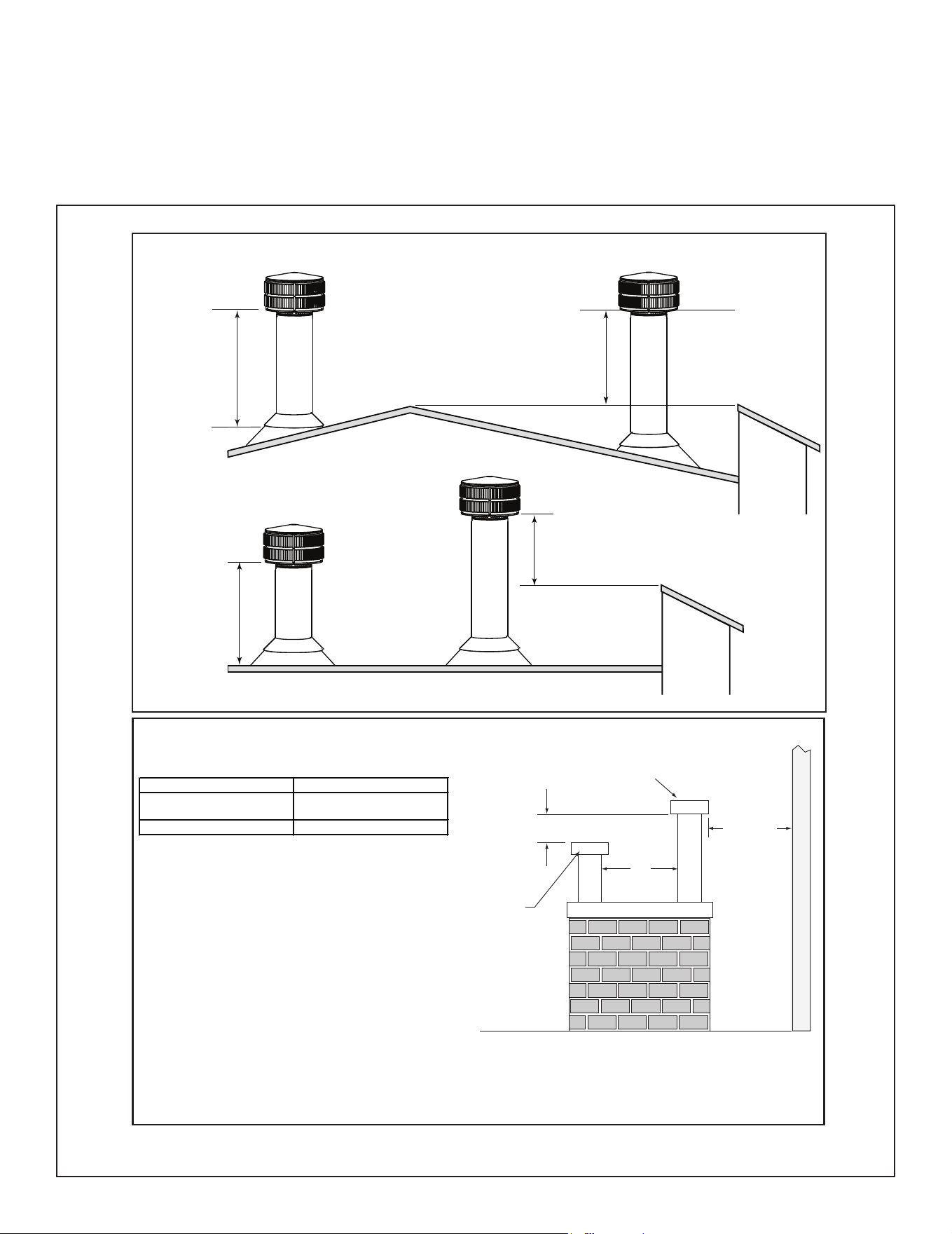
F. Cut out Hole in Roof
• RefertoFigure8.6.
• Plumb from roof to center of chimney.
• Driveanailupthroughrooftomarkcenterofpipe.
• Measuretoeithersideofnailandmarkthe14-1/2in.x
14-1/2in.(368mmx368mm)openingrequired.
• Measure opening on the horizontal; actual length may
be larger depending on roof pitch.
• Cut out and frame opening.
• Refer to Chapter 25 of the Uniform Building Code for
roof framing details.
28
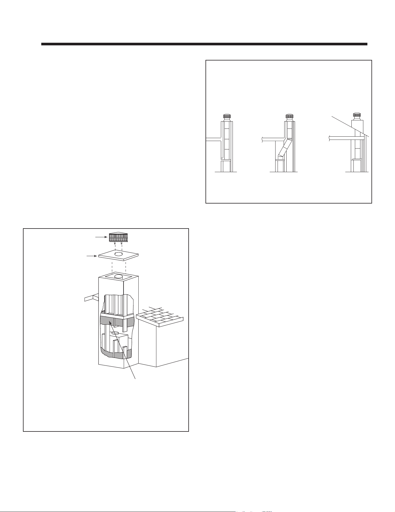
Slanted Roofs
Flat Roofs
Chimney must
extend 3 ft (.9 m)
above the roof
Chimney must extend 2 ft (.6 m)
above any portion of the roof or
adjacent structures within
10 ft (3 m) of the chimney
Chimney must
extend 3 ft (.9 m)
above the roof
Chimney must extend 2 ft (.6 m)
above any portion of the roof or
adjacent structures within
10 ft (3 m) of the chimney
Multiple Chimney Locations
A B
6 in. (minimum) up to 20 in.
152 mm/508 mm
18 in. minimum
457 mm
20 in. and over 0 in. minimum
Gas, Wood or Fuel Oil
Termination Cap
Wood
Minimum
(See
illustration
above)
B
Gas
Termination
Cap **
A *
Perpendicular Wall
*
If using decorative cap cover(s), this distance may need to be
increased. Refer to the installation instructions supplied with the
decorative cap cover.
**
In a staggered installation with both gas and wood terminations, the
wood termination cap must be higher than the gas termination cap.
Figure 8.10 Multiple Chimney Locations
I. Chimney Termination Requirements
• Installacapapprovedandlistedforthisreplacesystem.
• Locate cap where it will not become plugged by snow or other materials.
• Locate cap away from trees or other structures.
• Thebottomoftheterminationcapmustbeatleast3ft(.91m)abovetheroofANDatleast2ft(.61m)aboveanyportion
ofroofwithin10ft(3.05m)asshowninFigure8.10.
• ThedistancerequiredbetweencapsisshowninFigure8.10.
Outdoor Lifestyles by Hearth & Home Technologies • ODVILLA Wood Owners/Install • 4072-345 Rev B • 05/23
29
9 9
Chase Installations
Metal Chase Top
Round Termination Cap
Insulation in the
outside walls
of the chase
Figure 9.1 Chase Assembly
1 2 3
1. Fireplace and chimney enclosed in an exterior chase.
2. Chimney offset through exterior wall and enclosed in chase.
3. Chase constructed on roof.
Figure 9.2 Chase Constructions
A. Construct the Chase
Achaseisaverticalboxlikestructurebuilttoenclosethe
replace and/or its vent system. Vertical chimneys that
run on the outside of a building must be installed inside a
chase.
Construction of the chase may vary with the type of build-
ing. These instructions are not substitutes for the require-
ments of local building codes. Local building codes MUST
bechecked.
For outside chase construction, insulation is not required.
Buildingcodesrequirefalseceilingandceilingrestopsat
each oor of the chase or every 10 ft (3.05 m) of clear
spacetocontrolspreadofre.
Gaslineholesandotheropeningsshouldbecaulkedwith
hightemperaturecaulkorstuedwithunfacedberglass
insulation.
Three examples of chase applications are shown in Fig-
ure 9.2.
WARNING! Risk of Fire! DO NOT seal area between re
stop opening and chimney pipe except where they enter
the attic or leave the warm air envelope of the home (use
600° F sealant).
WARNING! Risk of Fire! You must maintain a minimum
2 in. (51 mm) air space clearance to insulation and other
materials surrounding the chimney system.
• Insulation and other materials must be rmly secured to
prevent accidental contact with chimney system.
• The chase must be properly blocked to prevent blown
insulation or other combustibles from entering and
making contact with replace or chimney.
• Failure to prevent contact between insulation or other
materials and chimney system may cause overheating
and re.
Outdoor Lifestyles by Hearth & Home Technologies • ODVILLA Wood Owners/Install • 4072-345 Rev B • 05/23
30
Slope Downward
(1/4 in. per foot
minimum)
Turn-down
Drip Edge
Chase
2 in. (51 mm) Collar
on Chase Top
.018 (26 ga) min.
Galvanized
Chase Top
Figure 9.3 Chase Top Construction
B. Install Fireplace & Chimney
Install as per Sections 7 and 8.
C. Install Chase Top
• You MUST use a chase top in a chase installation.
Chase tops are available from your Hearth & Home
Technologiesdealerormaybeeldconstructed.
• Include a turndown and drip edge to prevent water from
seeping into the chase.
• Include a 2 in. (51 mm) soldered, welded or spun collar
aroundpipeopeningtokeepwaterout.
• Providea1/8in.(3mm)gaparoundtheuepipe.
• Slope the chase top downward away from the opening.
WARNING! Risk of Fire! DO NOT caulk the pipe to
the chase top collar.
• Caulkallseamstopreventleaks.
• RefertoFigure9.3.
D. Install Termination Cap
Install the chimney sections up through the chase enclo-
sure.
• Caulktheoverlapseamofanyexposedpipesections
thatarelocatedabovetherooflinetopreventleaks.
• Refer to termination cap instructions.
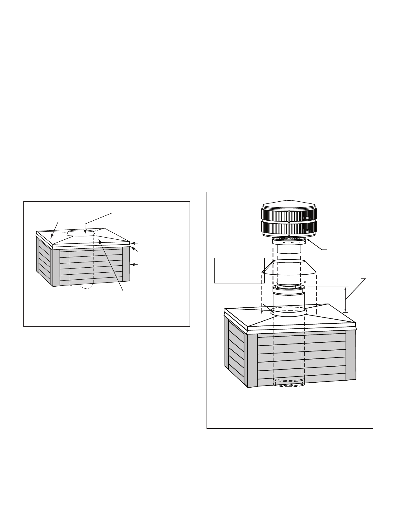
WARNING! Risk of Fire! The minimum overlap of cap
to pipe (as shown in the following illustrations) MUST
be met or chimney may separate from cap. Separation
allows sparks, heat and embers to escape.
NOTICE: Paint the termination cap with a rust-resistant
paint to protect against the eects of corrosion on those
parts exposed to the weather.
Outdoor Lifestyles by Hearth & Home Technologies • ODVILLA Wood Owners/Install • 4072-345 Rev B • 05/23
Storm
Collar
Chimney
Pipe
Chase Top
Termination
Cap
Chase
6 in. (153 mm)
Minimum top of
chase to top of
chimney pipe
Collar
2 in. (51 mm)
Minimum Height
Do NOT
block air holes
Caulk gaps between
storm collar & pipe,
and storm collar
& chase top.
Termination cap pipe and chimney section must be snapped
together to maintain an overlap of 1-1/2 in. (38 mm).
Slip
storm collar
around chimney pipe
before termination
cap pipe is snapped
into the chimney
pipe.
Figure 9.4 Installing a TR344 Round Termination Cap
• TR344RoundTerminationCap
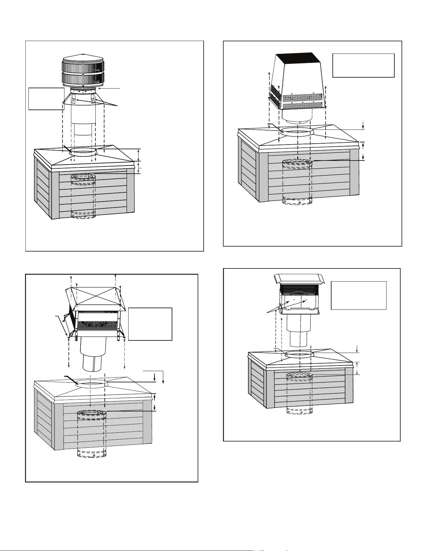
31Outdoor Lifestyles by Hearth & Home Technologies • ODVILLA Wood Owners/Install • 4072-345 Rev B • 05/23
Storm
Collar
Chimney
Pipe
Chase Top
Termination
Cap
Chase
4 3/4 in. (121 mm)
Maximum
Collar
2 in. (51 mm)
Minimum Height
Caulk gaps between
storm collar & pipe,
and storm collar
& chase top.
Do NOT
block air
holes
3 clip brackets.
Slip over chase collar
and attach with screws
provided.
Assemble
storm collar
around extended
termination cap
pipe
once cap is
installed.
The last section of pipe must
stop between 2 in. (51 mm)
above the top of the chase and
4 3/4 in. (121 mm) below the
top of the chase.
2 in. (51 mm)
maximum
Figure 9.5 Installing a TR342-B Round Telescoping Termination
Cap
Figure 9.6 Installing an ST375 Square Termination Cap
• ST375SquareTerminationCap
• TR342RoundTelescopingTerminationCap
Figure 9.7 Installing a TS345/TS345P Square Termination Cap
• TS345/TS345PSquareTerminationCap
Figure 9.8 Installing a TCT375 Terra Cotta Cap
• TCT375TerraCottaCap
Chimney
Pipe
Chase Top
Termination Cap
Chase
Collar
2 in. (51 mm)
Minimum Height
Place waterproof
caulk or sealer under
each flange of the
termination cap and
on top of each screw
to help prevent leaks.
Flange
2 in. (51 mm)
maximum
4 3/4 in. (121 mm)
maximum
The last section of pipe
must stop between 2 in. (51
mm) above the top of the
chase and 4 3/4 in. (121
mm) below the top of the
chase.
Chimney
Pipe
Chase Top
Termination Cap
Chase
Collar
2 in. (51 mm)
Minimum Height
Termination cap pipe and chimney section must overlap 1-1/2 in. (38 mm).
Place waterproof sealer under
each flange of the termination
cap and on top of each screw
to help prevent leaks.
2 in. (51 mm)
maximum
4 3/4 in. (121 mm)
maximum
The last section of pipe must
stop between 2 in. (51 mm)
above the top of the chase and
4 3/4 in. (121 mm) below the
top of the chase.
Chimney
Pipe
Chase Top
Termination Cap
Chase
Collar
2 in. (51 mm)
Minimum Height
Remove 2 screws
from front & back
to lift the top off
Place waterproof sealer
under each flange of the
termination cap and on
top of each screw to
help prevent leaks.
The last section of pipe
must stop between 2 in.
(51 mm) above top of
chase and 4-3/4 in. (121
mm) below top of chase
2 in. (51 mm)
4-3/4 in. (121 mm)
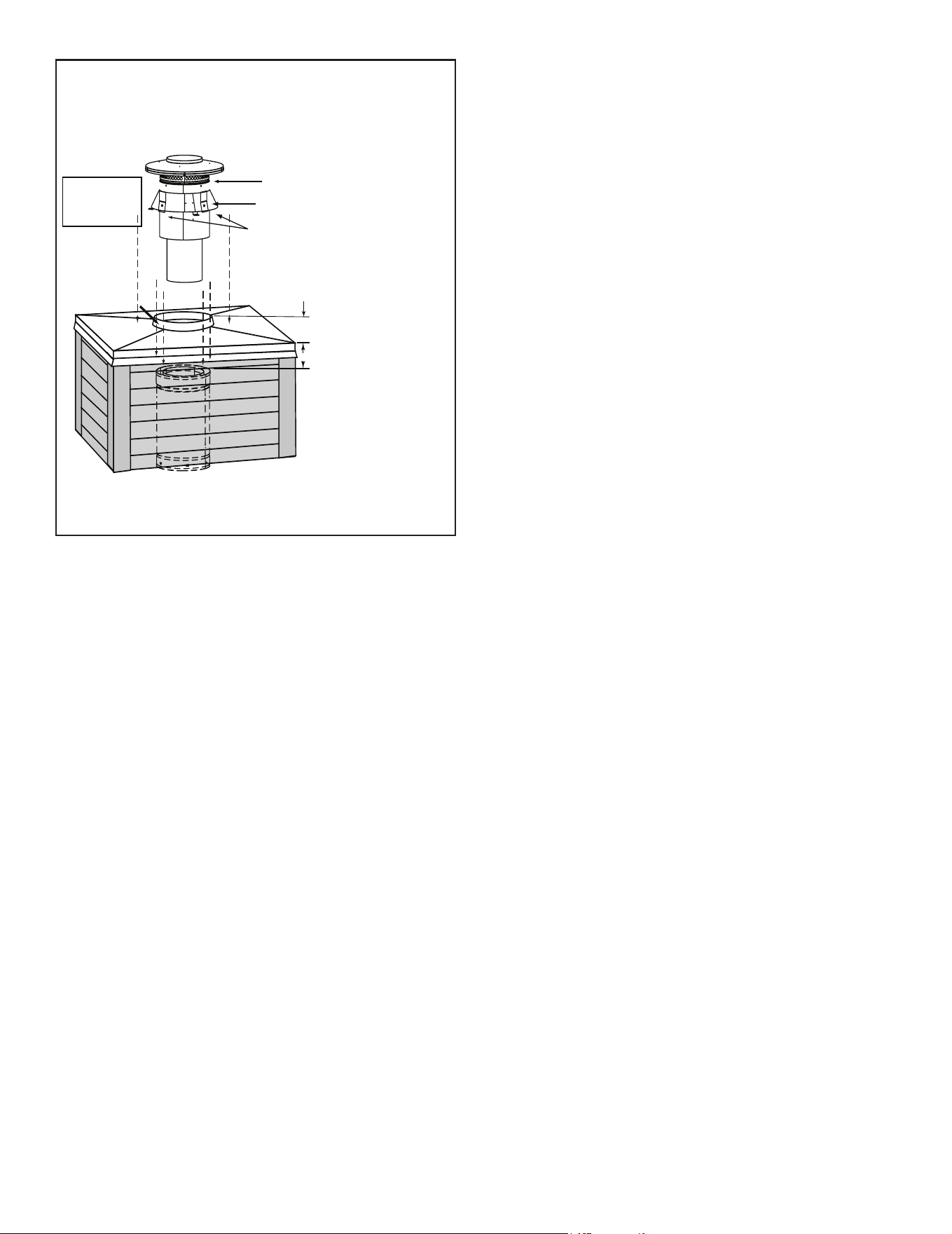
32
Storm Collar
Chimney
Pipe
Chase Top
Termination
Cap (not shown)
Chase
Collar
2 in. (51 mm)
Minimum Height
Caulk gaps between
storm collar & pipe,
and storm collar
& chase top.
Do NOT block
air holes
3 clip brackets.
Slip over chase collar
and attach with screws
provided.
Assemble
storm collar
around extended
termination cap
pipe
once cap is
installed.
CT
4-3/4 in. (121 mm)
2 in. (51 mm)
The last section of pipe must stop
between 2 in. (51 mm) above the
top of the chase and 4 3/4 in. (121
mm) below the top of the chase.
Figure 9.9 Installing a DTO134/DTO146/DTS134/DTS146 Cap
Outdoor Lifestyles by Hearth & Home Technologies • ODVILLA Wood Owners/Install • 4072-345 Rev B • 05/23
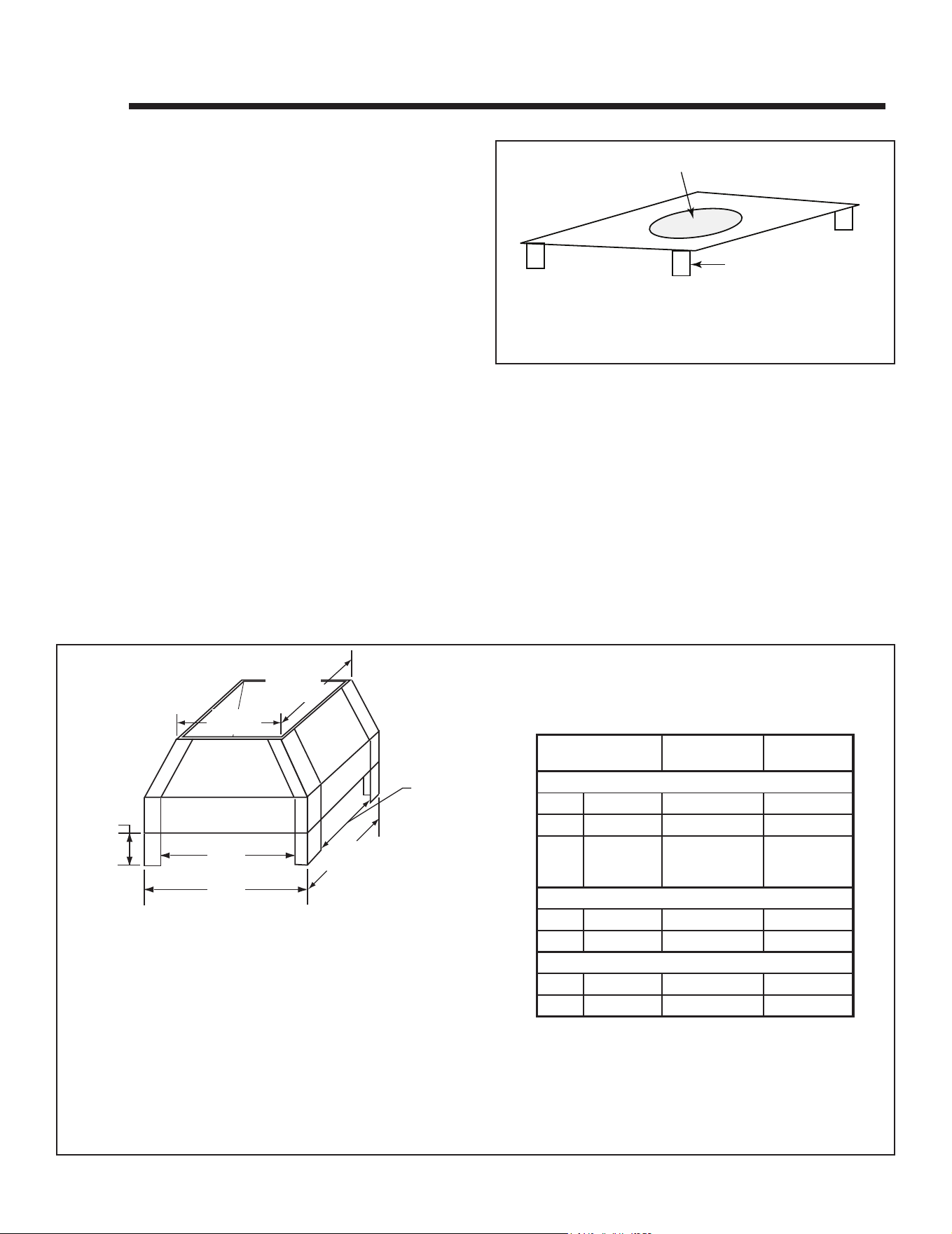
33
3 in. (76 mm) tall legs
Ø 17 1/2 in. (444.5 mm) Round Hole to fit over cap
Length x Width to fit inside shroud
Figure 10.1 Radiation Shield
10 10
Shrouds
• Chase top shrouds may be eld constructed where
permitted by regional building codes.
WARNING! Risk of Fire! Shrouds must be constructed
as specied. Improper construction may overheat chase
top.
NOTICE: Some regional codes require an agency-Listed
shroud. Consult your local building ocials.
• Hearth & Home Technologies Inc. supplies UL listed
shrouds. See your dealer for details.
• The following eld constructed shroud designs have
beentestedforHearthTechnologiesreplacesystems
and termination caps.
• Theshroudsmustbeconstructedfromaminimum.018
in.(26ga)thickaluminizedsteel.
A. Radiation Shield
• Some shrouds require a radiation shield. Use where
specied.
• Radiationshieldmustbeconstructedofminimum26ga
sheet metal.
3 in (76 mm)
minimum
Min.
Base Dim.
Min.
Base Dim.
Min.
Top Dim.
Min.
Top Dim.
Min. Opening
Width
Min. Opening
Width
Figure 10.2 Open Top Shroud Dimensions
B. Field Constructed Shrouds
• The wire mesh is optional but recommended and must
be.018in.thickminimum,1/2in.mesh.
Outdoor Lifestyles by Hearth & Home Technologies • ODVILLA Wood Owners/Install • 4072-345 Rev B • 05/23
Open Top Shroud (TR342 caps require radiation shield)
TS345
TR344
TR342B
TR342B/TR344
with TR-TVK
Min. Base Dims.
in 23x23 28 x 28 26x26
mm 584x584 711 x 711 660x660
Radiation
Shield Not
Required
Radiation Shield
Required
Radiation
Shield Not
Required
Min. Top Dims.
in 20x20 25 x 25 23x23
mm 508x508 635x635 584x584
Min. Opening Width
in 17 x 17 22 x 22 20x20
mm 432x432 559 x 559 508x508
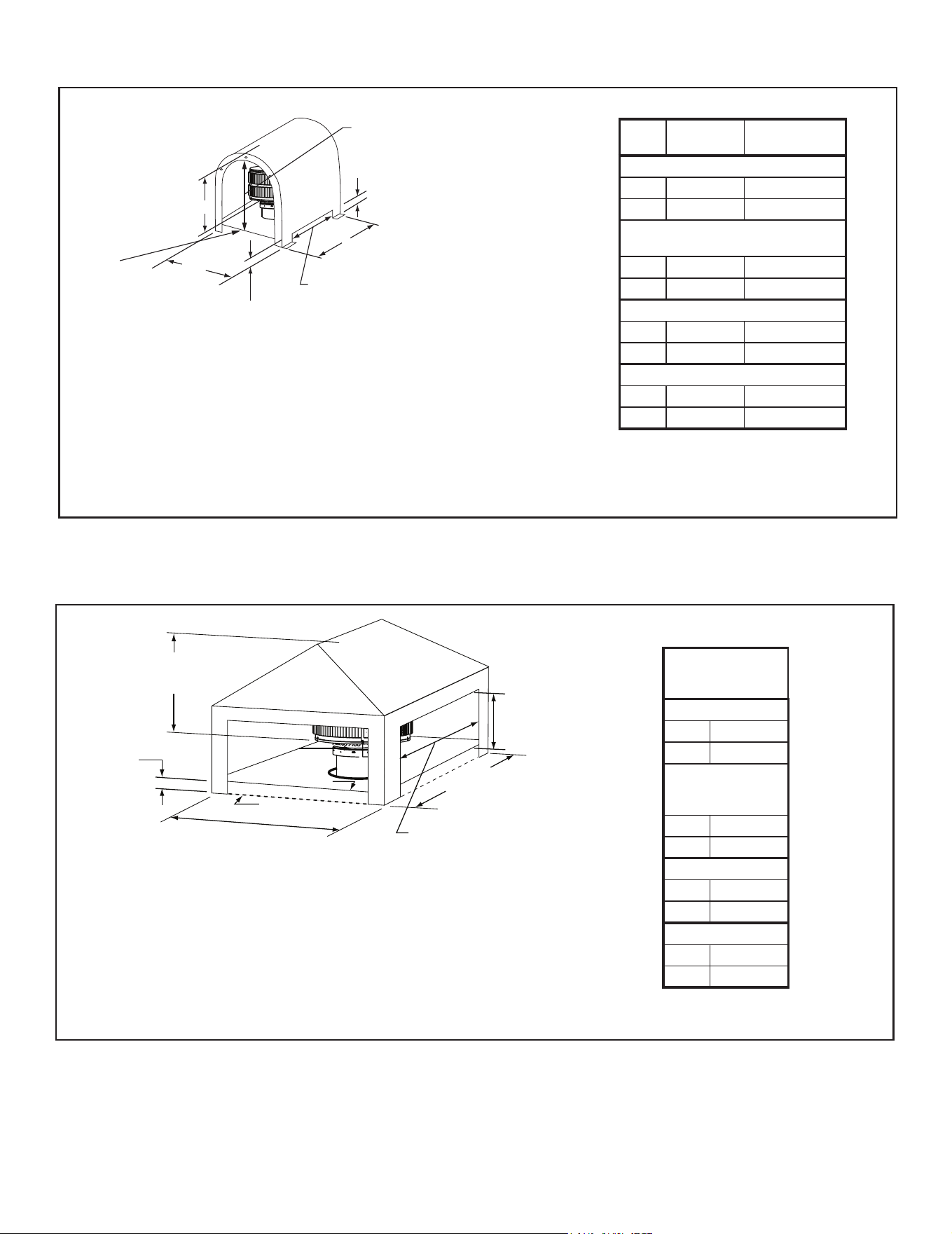
34
Figure 10.3 Mailbox Style Shroud Dimensions
Figure 10.4 Roofed Style Shroud Dimensions
Roofed Style Shroud (radiation shield required)
Mailbox Style Shroud (radiation shield required)
Outdoor Lifestyles by Hearth & Home Technologies • ODVILLA Wood Owners/Install • 4072-345 Rev B • 05/23
3 in. (76 mm)
Min. Opening Height
Min, Base Dim
Min. Height
above bottom of
termination
cap
Min.
Base Dim
3 in. (76 mm) Min.
Radiation Shield Height
from top of Chase
Min, Opening Width
Radiation
Shield
Minimum
Opening Height
TR344
TR342-B
TR342-B TR344/
with TR-TVK
Min. Base Dims.
in 26-1/2x28 28x30
mm 673x711 711x762
Min. Height Above Bottom of
Termination Cap
in 28-1/4 27-1/2
mm 718 698
Min. Opening Width
in 20-1/2 22
mm 521 559
Min. Opening Height
in 18-1/4 17-1/2
mm 464 445
Minimum
Opening
Height
Minimum
Base Dimension
Min. Opening Width
Min. Base Dimension
Minimum
Height above
Bottom of Termination Cap
Chase Top
Radiation Shield
3 in. (76 mm)
Radiation
Shield Height
Termination
Cap
TR342B/344
TR442B/444
or with TR-TVK
Min. Base Dims.
in 27 x 27
mm 686x686
Min. Height
Above Bottom of
Termination Cap
in 23
mm 584
Min. Opening Width
in 21
mm 533
Min. Opening Height
in 12
mm 305

35
11 11
Finishing
A. Non-Combustible Materials
• Materials which will not ignite and burn, composed of
any combination of the following:
- Steel - Iron
- Brick - Tile
- Concrete - Slate
- Glass - Plasters
• Materials reported as passing ASTM E 136, Standard
Test Method for Behavior of Metals, in a Vertical Tube
Furnace at 750° C
B. Combustible Materials
• Materials made of or surfaced with any of the following
materials:
- Wood - Compressed paper
- Plantbers - Plastic
• Anymaterialthatcanigniteandburn;ameproofedor
not, plastered or un-plastered
C. Hearth Extension
WARNING! Risk of re! High temperatures, sparks,
embers or other burning material falling from the replace
may ignite ooring or concealed combustible surfaces.
• Protective metal hearth strips MUST be installed.
• Hearth extensions MUST be installed exactly as
specied.
Table 11.1
Hearth Extension Insulation Alternatives-Total minimum R Value must equal 1.03
Material
k per inch
thick
r per inch
thick
Minimum
thickness
required
Hearth&HomeHX3,HX4(Micore300™) 0.49 2.06 1/2 in.
USGMicore160™ 0.39 2.54 1/2 in.
USGDurock™CementBoard 1.92 0.52 2 in.
Cement Mortor 5.0 0.20 5-1/8 in.
CommonBrick 5.0 0.20 5-1/8 in.
Ceramic Tile 12.50 0.08 12-1/4in.
Armstrong™PrivacyGuardPlus 0.46 2.18 1/2 in.
Marble 14.3-20.0 0.07-0.05 14-5/8in.-20-3/8in.
R = 1/k x inches of thickness
• YouMUSTuseahearthextensionwiththisreplace.
• Refer to Figure 11.1 for minimum dimensions.
• Thisreplacehasbeentestedandapprovedforusewith
a hearth extension insulated to a minimum R value of
1.03.
• The hearth extension material MUST be covered with
tile, stone or other non-combustible material.
• Manufactured hearth materials will usually have a
published R value (resistance to heat) or k value
(conductivity of heat). Refer to the formula in Table 11.1
toconvertakvaluetoanRvalue,
• Refer to Table 11.2 for hearth extension insulation
alternatives.
Table 11.2
Outdoor Lifestyles by Hearth & Home Technologies • ODVILLA Wood Owners/Install • 4072-345 Rev B • 05/23
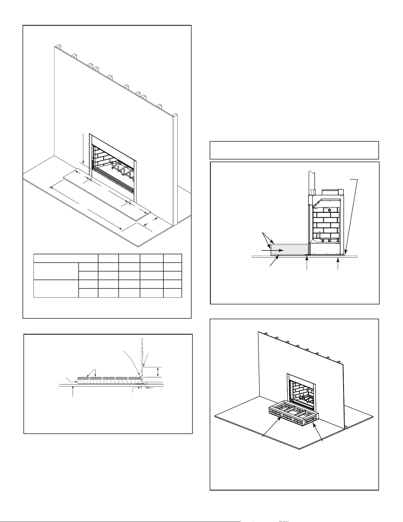
36
IMPORTANT! Hearth extension design must be
determinedbeforeinstallationofreplace.
Floor
Non-combustible
Framing Material
Non-combustible
Finishing Material
Protective Metal
Hearth Strips
1/2 in. Micore
or equivalent
insulation
Non-combustible
Material
Figure 11.3 Raised Platform Hearth Extension Detail
Raised Hearth Extension Framing
WARNING! Risk of Fire. A raised hearth extension built
ush with the replace opening (Figure 11.3) or less than
4 in. (102 mm) below the replace opening requires the
replace be installed on a non-combustible surface.
The hearth framing must be constructed of non-combus-
tible materials (Figure 11.2) and placed on 1/2 in. Micore,
orequivalentmaterial(Figure11.4).Whencreatingthe
platform,allowforthethicknessofthenon-combustible
nishingmaterials(Figure11.5).
Non-combustible
Framing Material
1/2 in. Micore or
equivalent insulation
Figure 11.4 Raised Platform Hearth Extension-Framing Materials
2 in. (51 mm) of the Protective
Metal Hearth Strip is required
under the front of the fireplace
Tile, stone or other
non-combustible material
Floor constructed of wood or
other combustible material
Fireplace
Opening
4 in.
(102 mm) min.
Continuous, non-
combustible sealant
1/2 in. Micore Hearth
Extension (or
equivalent insulation)
See Table 11.2.
Figure 11.2 Hearth Extension Construction
B
A
C
C
D
4 in. (102 mm)
minimum between
bottom of fireplace opening
and finished surface of hearth extension
Figure 11.1 Hearth Extension Dimensions
Model# A B C D
ODVILLA-36 in. 36 52 8 16
mm 914 1321 203 406
ODVILLA-42 in. 42 66 12 20
mm 1067 1676 305 508
Outdoor Lifestyles by Hearth & Home Technologies • ODVILLA Wood Owners/Install • 4072-345 Rev B • 05/23
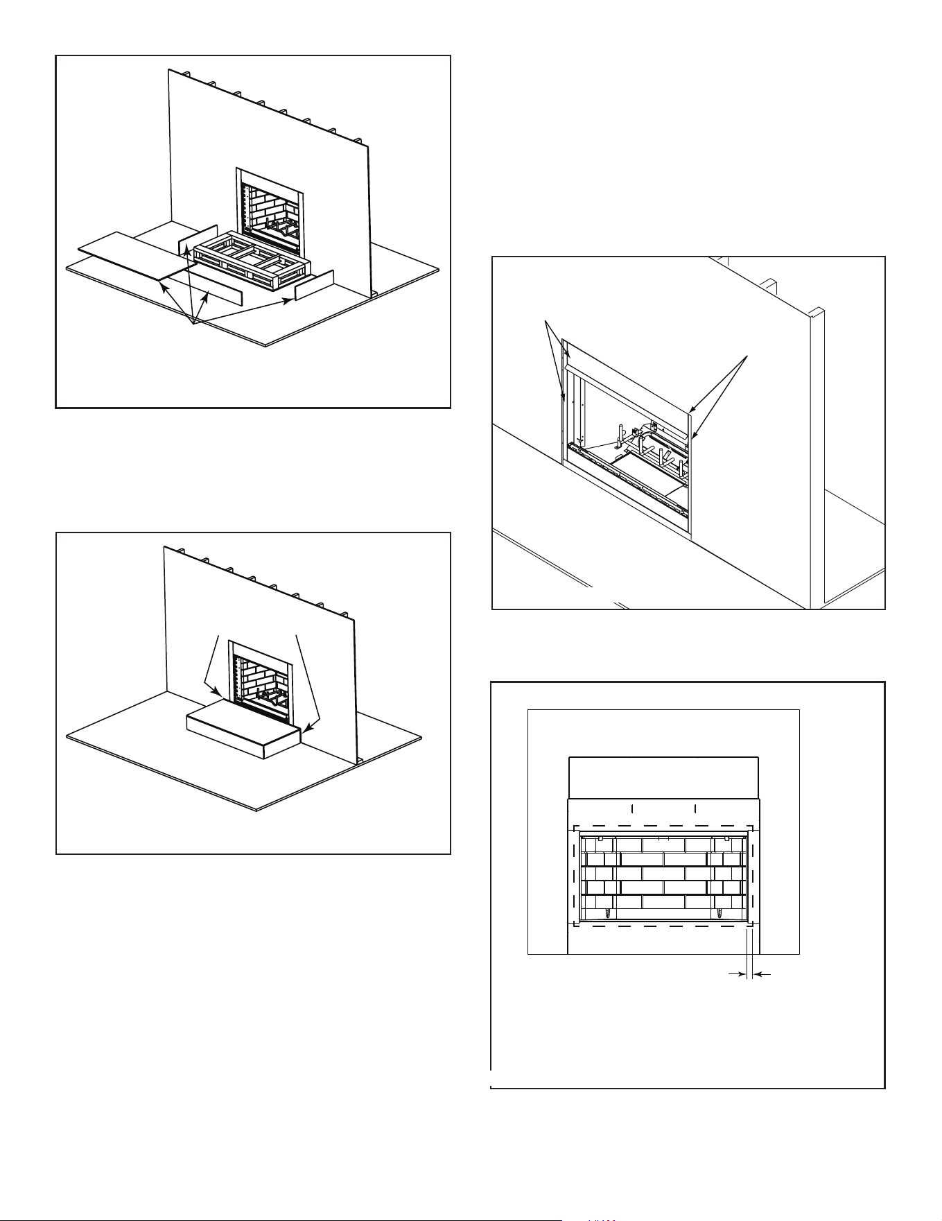
37
Non-combustible
Finishing Materials
Figure 11.5 Raised Platform Hearth Extension-Finishing Materi-
als
Non-combustible Sealant
After completing the framing and applying the facing mate-
rials over the framing, a bead of non-combustible sealant
mustbeusedto close oany gapsat thetop andsides
betweenthereplacehearth.
Non-combustible Sealant
Figure 11.6 Place Non-combustible Sealant
D. Finishing Material
Refer to Sections 11.A. and Sections 11.B. for combus-
tible/non-combustible materials. Refer to Figure 11.7 for
non-combustible zone.
WARNING! Risk of Fire! You must maintain clearances.
• Use only non-combustible framing material below
standos.
• Sheetrock, wood or other combustibles must NOT be
used as sheathing or facing in the non-combustible
zone.
• DO NOT cover metal replace front with combustible
materials.
• Install combustible materials only to specied clearances
on top front and side edges.
• Complete framing and apply drywall over framing.
• A bead of 300° F minimum non-combustible sealant
mustbeusedtocloseoanygapsatthetopandsides
between the fireplace and drywall/non-combustible
materialtopreventcoldairleaks.
• Large gaps can be bridged with fiberglass rope
gasket.
• Only non-combustible materials may be used to cover
themetalreplacefront.SeeFigure11.8.
These metal surfaces
will be covered
with non-combustible
material.
300° silicone
sealant around
edge of fireplace
and drywall.
Figure 11.7 Non-combustible Facing
1 in. Maximum
( All sides)
CAUTION:This fireplace requires the front of the
appliance to be covered with a noncombustible material
(e.g. stone, marble, tile, etc.). A maximum of 1 in. of exposed
metal on all sides is permitted.
Figure 11.8 Non-combustible Material
Outdoor Lifestyles by Hearth & Home Technologies • ODVILLA Wood Owners/Install • 4072-345 Rev B • 05/23
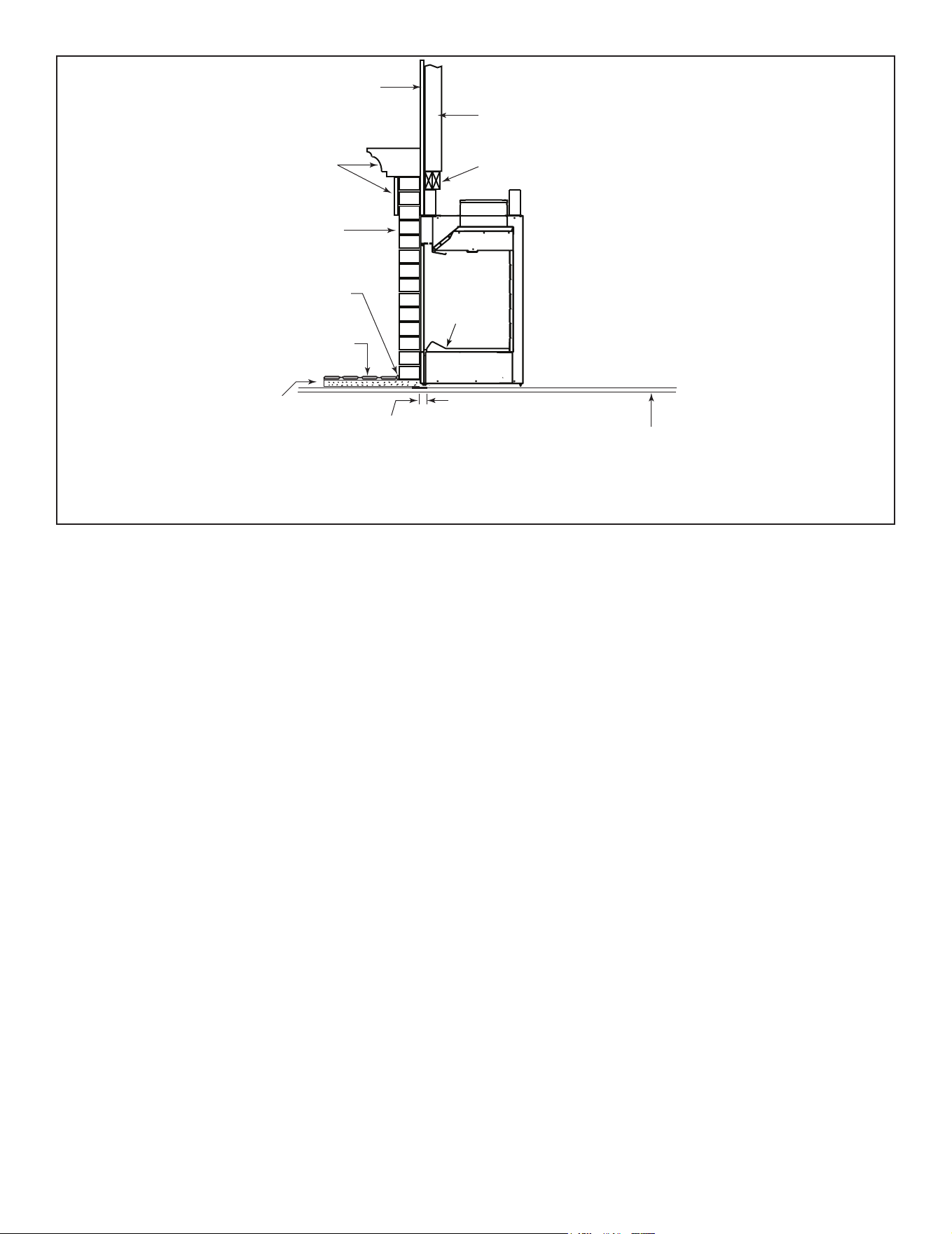
38
Metal strips are placed 2 in. (51 mm)
under the front of the fireplace and must
extend beyond the front and sides of
fireplace opening by 2 in. (51 mm)
Continuous,
non-combustible sealant
Floor constructed of wood or
other combustible material
1/2 in. Micore
or equivilent
insulation
Hearth
Refractory
Finished combustible wall
Combustible material
Non-combustible
decorative facing
(up to full brick depth)
2 x 4 header, flush with
front of stand-offs
Tile, stone or other
non-combustible material
Flat 2 x 4 stud wall
Figure 11.9 Decorative Facing
Note:
IfLintelBarisusedmakesure
it does not cover combustible
material.
Outdoor Lifestyles by Hearth & Home Technologies • ODVILLA Wood Owners/Install • 4072-345 Rev B • 05/23
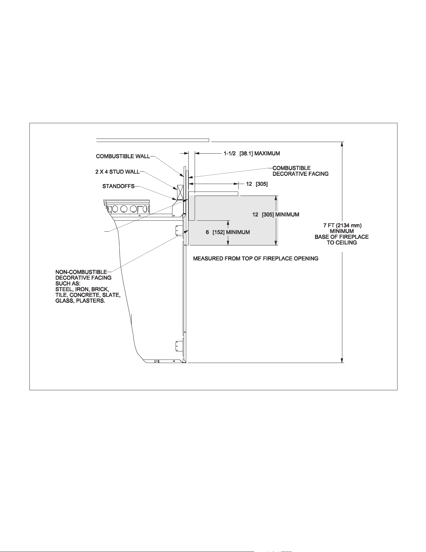
39
E. Combustible Mantel
• RefertoshadedareasofFigure11.10forthelocationanddimensionsofacombustiblemantel.
• Acombustiblemantelmaybepositionednolowerthan12in.(305mm)abovethetopofthereplaceopening.
• Acombustiblemantelmayhaveamaximumdepthof12in.(305mm).
• Combustibletrimandmaterialscannotbeplacedwithin6in.(152mm)ofthereplaceopening(toporsides).
• Combustiblematerialsprojectingmorethan11/2in.(38mm)shallnotbeplacedwithin12in.(305mm)fromthetopof
thereplaceopening.
• Combustibletrimmustnotcoverthemetalsurfacesofthereplace.
• Mantel clearance is in accordance with Section 7-3.3.3 of ANSI/NFPA211.
Figure 11.10 Clearances to Mantels or other Combustibles above Fireplace
WARNING:
SEAL JOINT WITH
NON-COMBUSTIBLE
SEALANT TO
PREVENT HEAT FROM
BEING DRAWN INTO
THE WALL CAVITY.
Outdoor Lifestyles by Hearth & Home Technologies • ODVILLA Wood Owners/Install • 4072-345 Rev B • 05/23
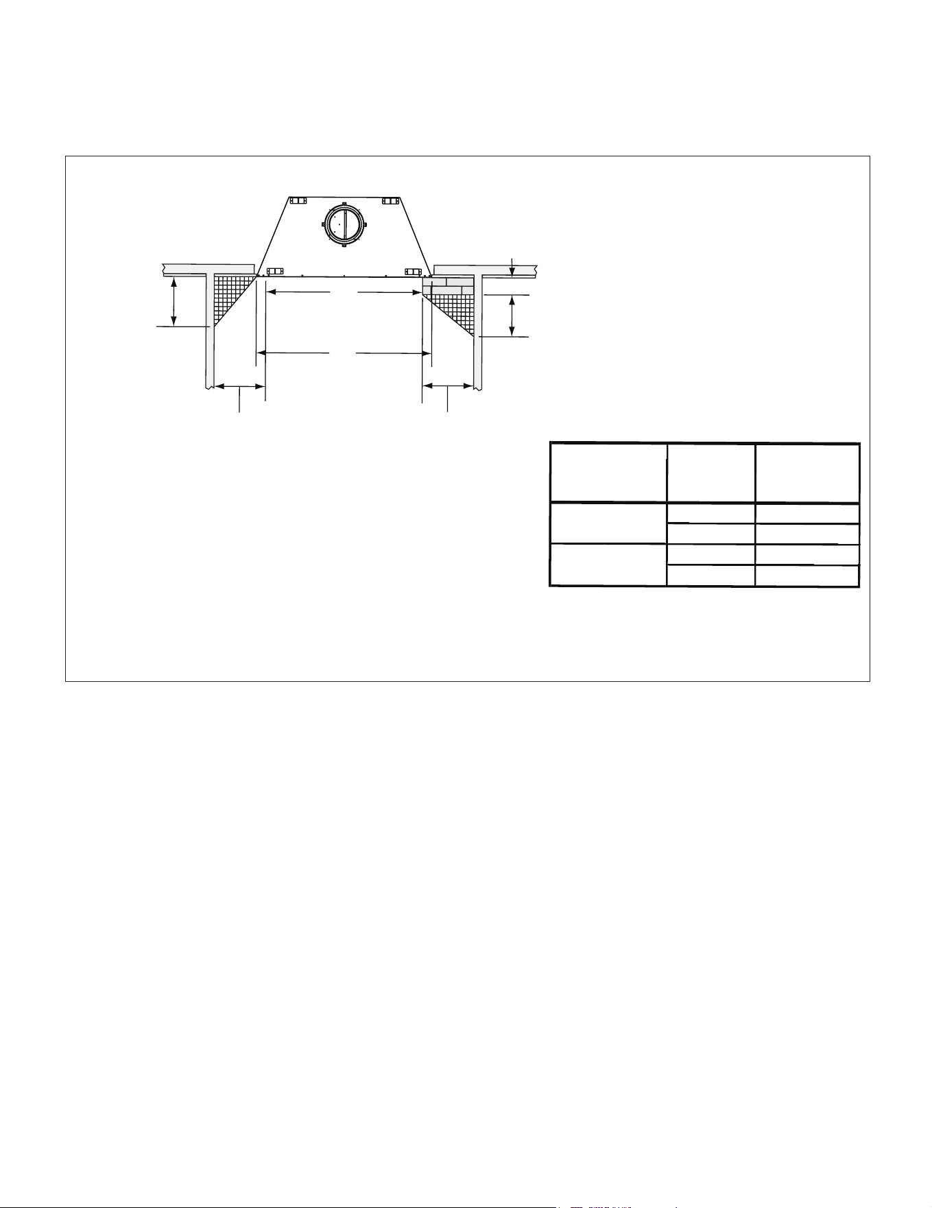
40
F. Sidewalls/Surrounds
• Adjacentcombustiblesidewallsmustbelocatedaminimumof12in.(305mm)fromthereplaceopening.
• Combustible or non-combustible mantel legs, surrounds and stub walls may be constructed per Figure 11.11.
Figure 11.11 Mantel Leg or Wall Projections (acceptable on both sides of opening)
Model
A
Fireplace
opening
B
Outside
Dimensions
36 in. 41 in.
914 mm 1041 mm
42 in. 47 in.
1067 mm 1194 mm
ODVILLA-42
ODVILLA-36
B
A
9 3/4 in.
[248 mm]
12 in.
[305 mm]
12 in.
[305 mm]
11 1/4 in.
[286 mm]
FLUSH
FRONT
4 in.
[102 mm]
BRICK
FRONT
50° angle
39° angle
Outdoor Lifestyles by Hearth & Home Technologies • ODVILLA Wood Owners/Install • 4072-345 Rev B • 05/23
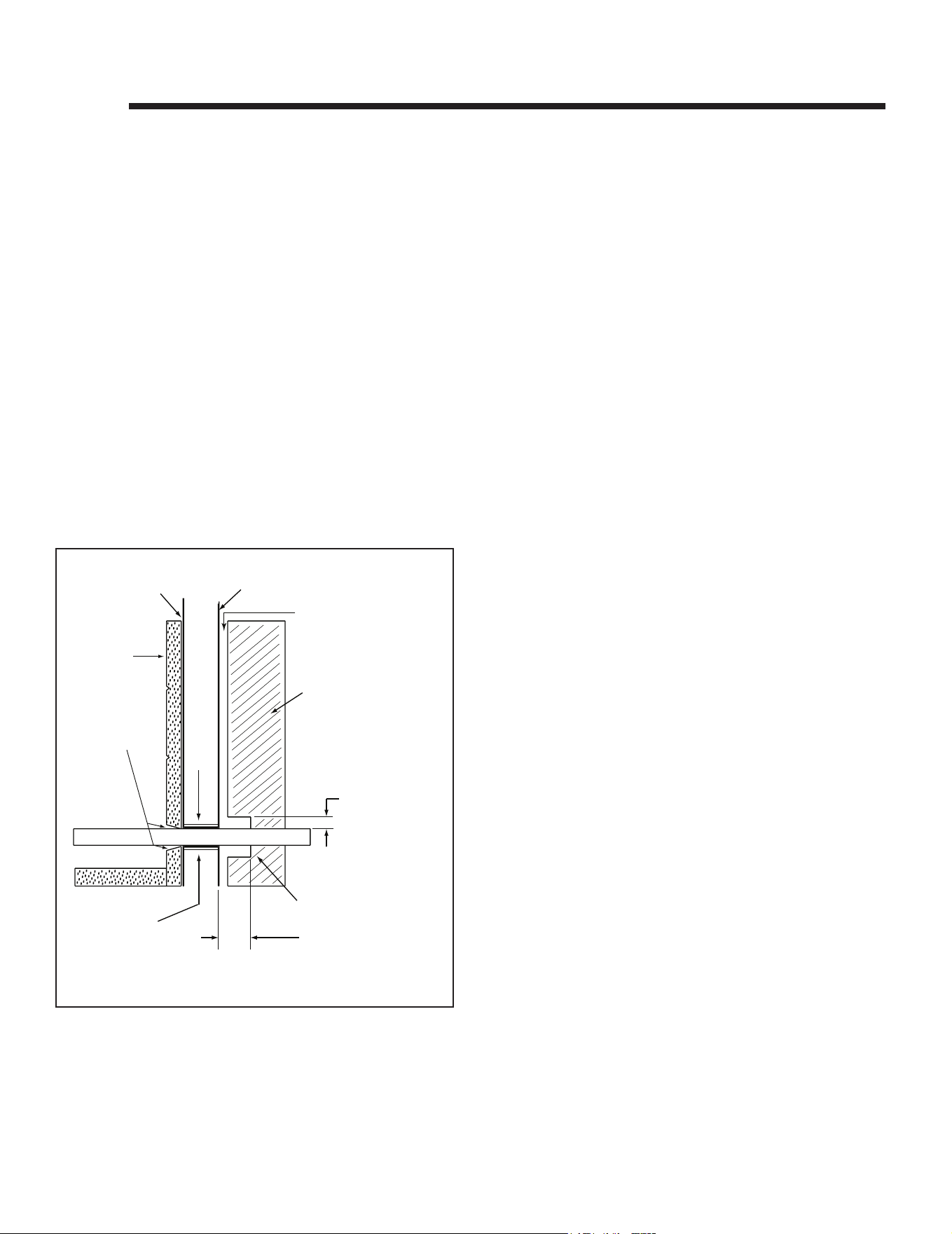
41
Firebox
Repack
insulation
knockout
Combustible
materials
Maintain air clearance
to combustibles.
Gas line
Combustible materials
may be located at zero
clearance to gas line
beyond 4 in. (102 mm)
from fireplace side.
Gas line
1 1/2 in. (38 mm)
air space around
gas line
Refractory
Seal with
fireplace mortar
or non-combust-
ible sealant
4 in.
(102 mm)
Outer shell
of fireplace
Figure 12.1 Gas Line Installation
12 12
Accessories
A. Gas Log/Lighter Provision
WARNING! Fire and/or Asphyxiation Risk! Use with
solid wood fuel or decorative gas appliance only. Gas re
generates fumes.
Acertiedgasloglighterordecorativegaslogset,vented
orunventedcanbeinstalledinthisreplace.
• Maximuminputis100,000BTU/hr.
• Decorative gas appliance must be certied to ANSI
Z21.60 “Standard for Decorative Gas Appliances for
Installation in Vented Fireplaces”.
• Must be installed in accordance with the National Fuel
Gas Code, ANSI Z223.1.
• Agaslogsetmustincorporateagasshuto.
• Knockoutsareprovidedonbothsidesofthereplace
andinrefractoriesfor1/2in.(13mm)gasline.
• Sealrefractoryaroundgaslinewithreplacemortaror
a non-combustible sealant.
Outdoor Lifestyles by Hearth & Home Technologies • ODVILLA Wood Owners/Install • 4072-345 Rev B • 05/23
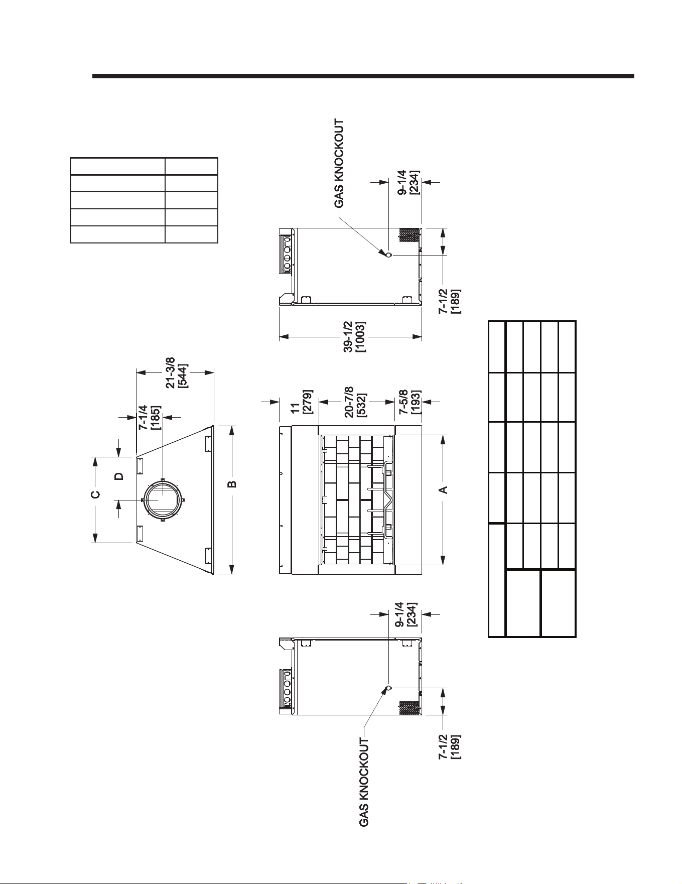
42
13 13
Reference Materials
A. Appliance Dimensions/Weight
A B C D
in. 36 41 23 3/4 11 7/8
mm 914 1041 603 302
in. 42 47 29 3/4 14 7/8
mm 1067 1194 756 378
Model #
ODVILLA-36
ODVILLA-42
Model Pounds
ODVILLA-36H-B 205
ODVILLA-36T-B 190
ODVILLA-42H-B 220
ODVILLA-42T-B 205
Appliance Weight Table
Outdoor Lifestyles by Hearth & Home Technologies • ODVILLA Wood Owners/Install • 4072-345 Rev B • 05/23
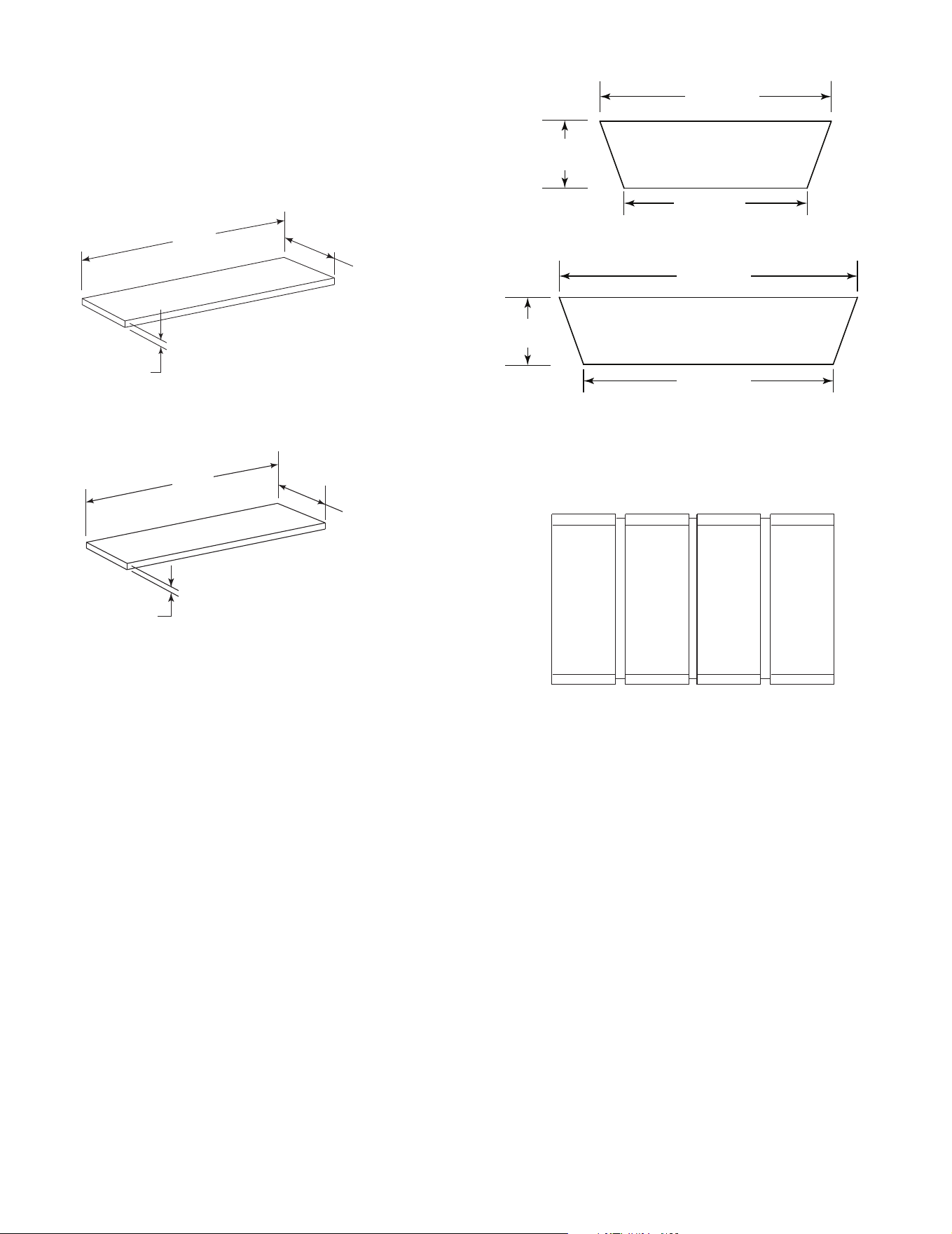
43
B. Optional Components
16 in.
(406 mm)
52 in.
(1321 mm)
1/2 in.
(13 mm)
20 in.
(508 mm)
66 in.
(1676 mm)
1/2 in.
(13 mm)
HX3 Hearth Extension
HX4 Hearth Extension
Bifold Glass Doors
ODVGF-36, ODVGF-42
Drain Pan
ODVILLA-36DP
ODVILLA-42DP
21.61in
(549 mm)
21.61 in
(549 mm)
41.45 in
(1053 mm)
47.45 in
(1205 mm)
ODVILLA-36DP
Outside dimensions
ODVILLA-42DP
Outside dimensions
29.99 in
(762mm)
23.99 in
(609 mm)
Outdoor Lifestyles by Hearth & Home Technologies • ODVILLA Wood Owners/Install • 4072-345 Rev B • 05/23
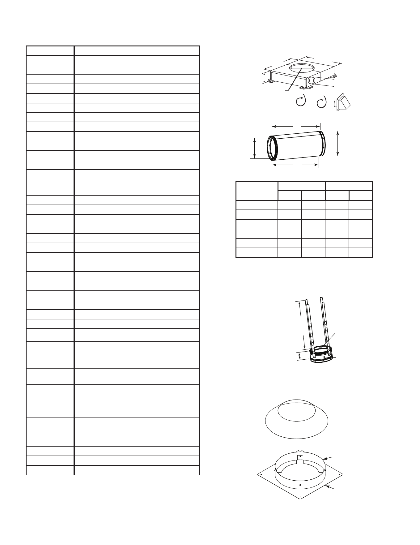
44
C. Chimney Components
Thefollowingpicturesshowonlythosechimneycomponentswhichmaybesafelyusedwiththisreplace.
TR-TVK
TR Top Vent Kit
Outdoor Lifestyles by Hearth & Home Technologies • ODVILLA Wood Owners/Install • 4072-345 Rev B • 05/23
Catalog # Description
CAK4A Chimney Air Kit
SL306 ChimneySection-6in.(152mm)long
SL312 ChimneySection-12in.(305mm)long
SL318 ChimneySection-18in.(457mm)long
SL324 ChimneySection-24in.(610mm)long
SL336 ChimneySection-36in.(914mm)long
SL348 ChimneySection-48in.(1219mm)long
SL3 Chimney Stabilizer
SL315 ChimneyOset/Return-15deg
SL330 ChimneyOset/Return-30deg
FS338 Ceiling Firestop - Straight
FS339 Ceiling Firestop - 15 deg
FS340 CeilingFirestop-30deg
AS8
SL300StraightAtticInsulationShield,24in.
(610mm)
JB877 Chimney Joint Band
CB876 ChimneyBracket
RF370 RoofFlashing-Flatto6/12Pitch
RF371 RoofFlashing-6/12to12/12Pitch
TR344 Round Termination Cap
TR342 Round Telescoping Termination Cap
ST375 Square Termination Cap
TS345 Square Termination Cap
TS345P Square Termination Cap - Painted
TCT375 Terra Cotta Termination Cap
CT35 Chase Top
DTO134 Short Octagon Decorative Cap
DTO146 Tall Octagon Decorative Cap
DTS134 Short Square Decorative Cap
DTS146 Tall Square Decorative Cap
LDS33 DecorativeShroud-3ftx3ft(.91mx.91m)
LDS46 DecorativeShroud-4ftx6ft(1.22mx1.83m)
LDS-BV
DecorativeShroud-26in.x26in.(660mmx
660mm)
Field Constructed Shrouds (See “Woodburning
Termination Cap”)
CT-3A
Adapter - May be used with the following copper
caps
CT-Series
DT-Series
CAS8 Attic Shield Kit
ODVILLA-36DP 36T/36HDrainPan
ODVILLA-42DP 42T/42HDrainPan
SL3 Vent Stabilizer
Chimney Sections
A = Actual Length
B = Eective Length (length of chimney
part after it has been snapped to an-
other)
8 in.
(203 mm)
10-1/2 in.
(267 mm)
A
B
20-3/4 in.
(527 mm)
Inside
Diameter
8 in.
(203 mm)
Outside
Diameter
10-1/2 in.
(267 mm)
4-3/4 in. (121 mm)
Effective Height
CAK4A Chimney Air Kit
10-1/2 in.
(267 mm)
12 in.
(305 mm)
5-1/4 in.
(133 mm)
4 in. (102 mm)
12 in.
(305 mm)
Storm Collar
Attic Collar
Attic Spacer
Attic Shield Kit
Catalog #
A B
in mm in mm
SL306 6 152 4-3/4 121
SL312 12 305 10-3/4 273
SL318 18 457 16-3/4 425
SL324 24 610 22-3/4 578
SL336 36 914 34-3/4 883
SL348 48 1219 46-3/4 1187
CT-3A-B
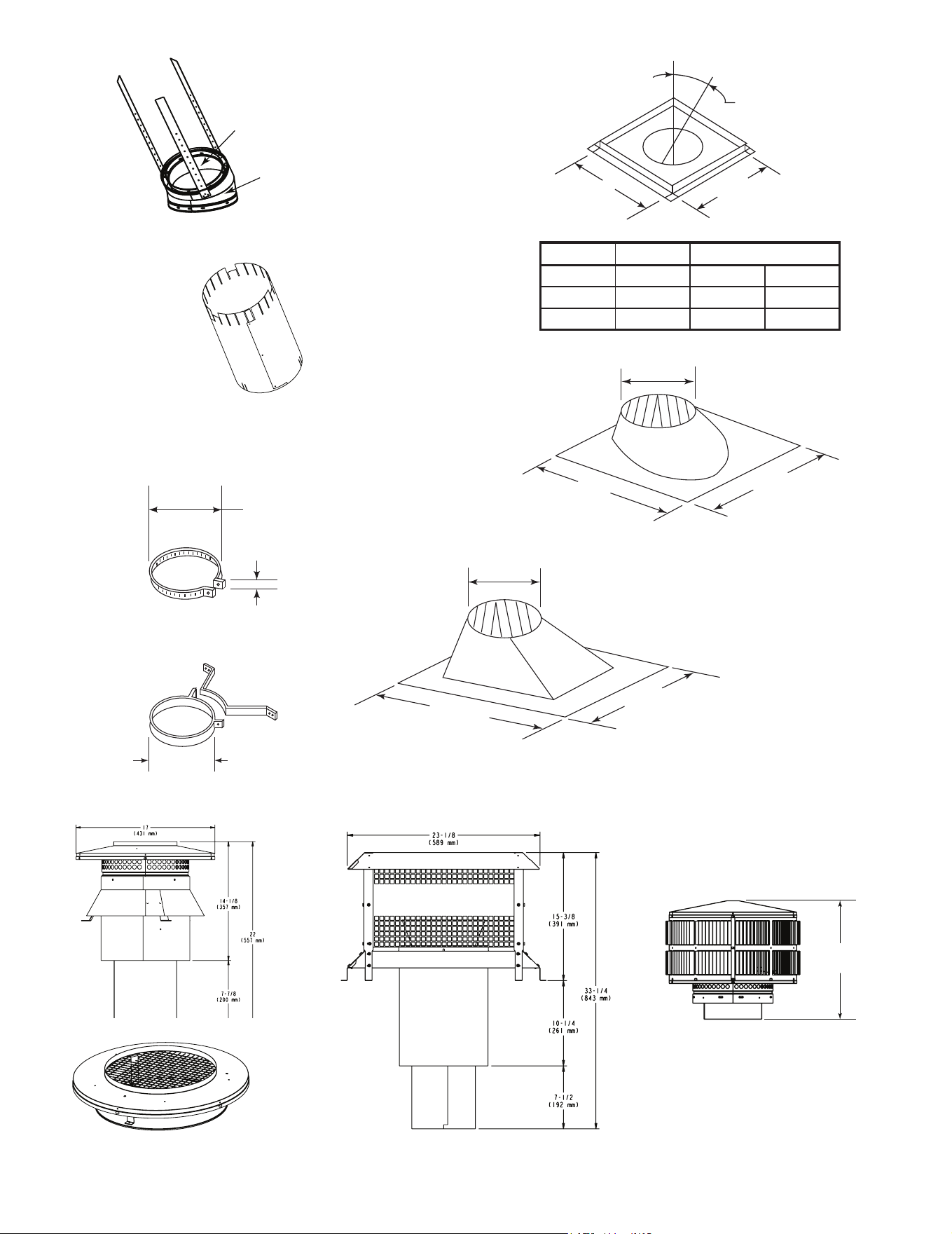
45
TR-TVK
TR Top Vent Kit
Outdoor Lifestyles by Hearth & Home Technologies • ODVILLA Wood Owners/Install • 4072-345 Rev B • 05/23
A
B
14-1/2 in.
(368 mm)
Ceiling Firestop
Assembled
Diameter: 14 1/2 in./368 mm
Height: 24 in./610 mm
AS8 Straight Attic Insulation Shield
10-1/2 in.
(267 mm)
CB876 Chimney Joint Band
RF371 Roof Flashing
RF370 Roof Flashing
Catalog # A B
FS338 0-deg. 14-1/2in. 368mm
FS339 15-deg. 18-3/8in. 467mm
FS340 30-deg. 23in. 584mm
JB877 Chimney Joint Band
2 in. (51 mm)
10-1/2 in.
(267 mm)
24-5/8 in.
(625 mm)
27-3/8 in.
(695 mm)
12 in.
(305 mm)
31 in.
(787 mm)
24-5/8 in.
(625 mm)
12 in.
(305 mm)
15-3/4 in.
(400 mm)
TR344 Round Termination Cap
Inside
Diameter
8 in. (203 mm)
Outside
Diameter
10-1/2 in.
(267 mm)
SL315 Chimney Oset/Return - Eective Height 13-3/8in. (380 mm)
SL330 Chimney Oset/Return - Eective Height 15-1/2in. (394 mm)
CT-3A-B
ST375 Square Termination Cap
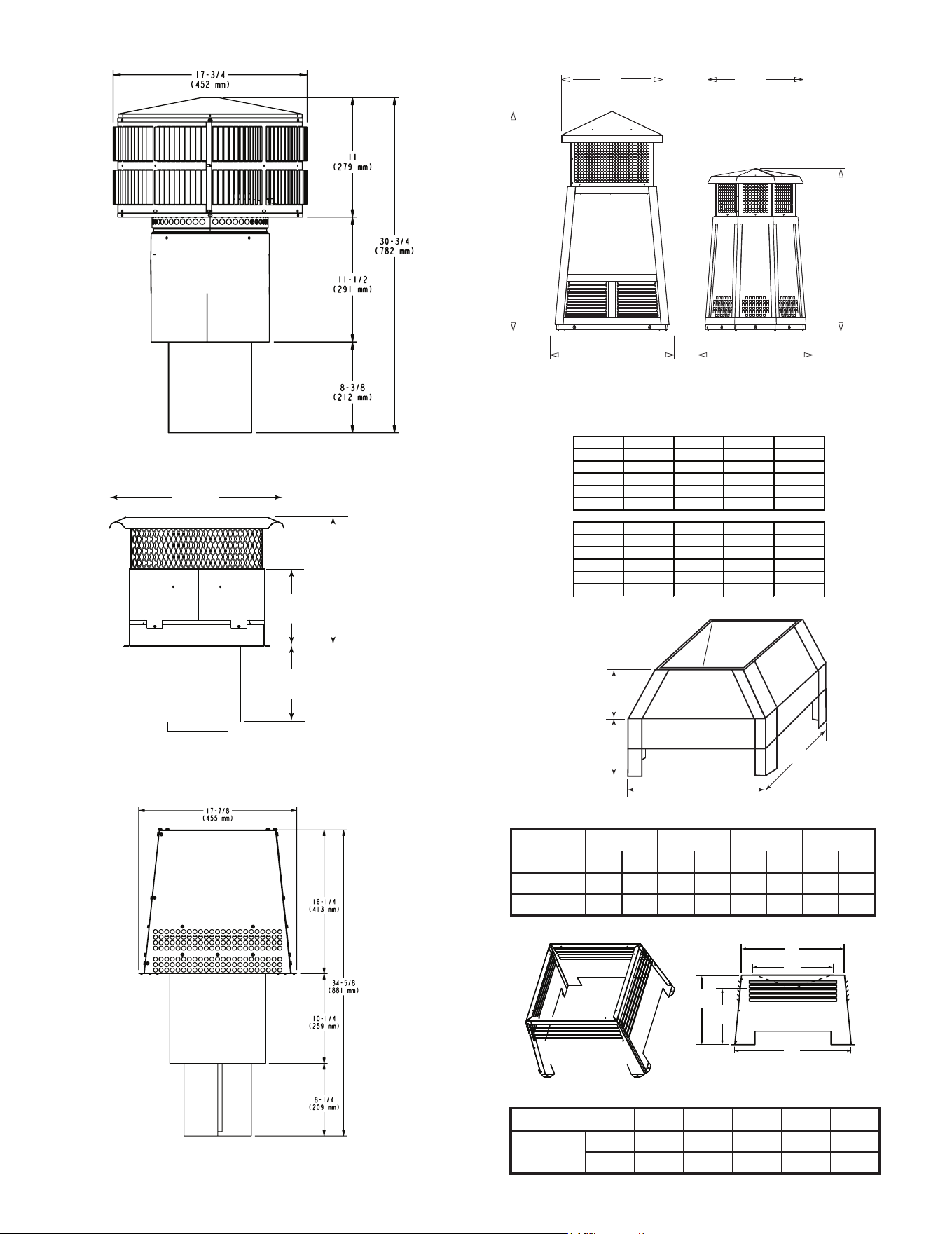
46
A
B
C
D
LDS33/LDS46 Decorative Shroud
E
D
A
C
B
LDS-BV Decorative Shroud
B
C
B
A
C
A
DTS134/DTS146 DTO134/DTO146 Decorative Caps
DTO134
A B C
in
34 20 24
mm
864 508 610
DTO146
in
46 22.7 26
mm
1168 576 660
DTS134
A B C
in
34 21.18 24
mm
864 538 610
DTS146
in
46 21.18 26
mm
1168 538 660
Catalog #
A B C D
in. mm in. mm in. mm in. mm
LDS33 36 914 36 914 8.5 216 11 279
LDS46 48 1219 72 1829 8.5 216 11 279
Catalog # A B C D E
LDS-BV
in. 26 12.5 15.5 22 23
mm 660 318 394 533 584
Outdoor Lifestyles by Hearth & Home Technologies • ODVILLA Wood Owners/Install • 4072-345 Rev B • 05/23
TCT375 Terra Cotta Cap
22 1/2 in.
(572 mm)
9 1/2 in.
(241 mm)
16 1/2 in.
(419 mm)
9 1/2 in.
(241 mm)
TS345/TS345P Square Termination Cap
TR342-B Round Telescoping Termination Cap
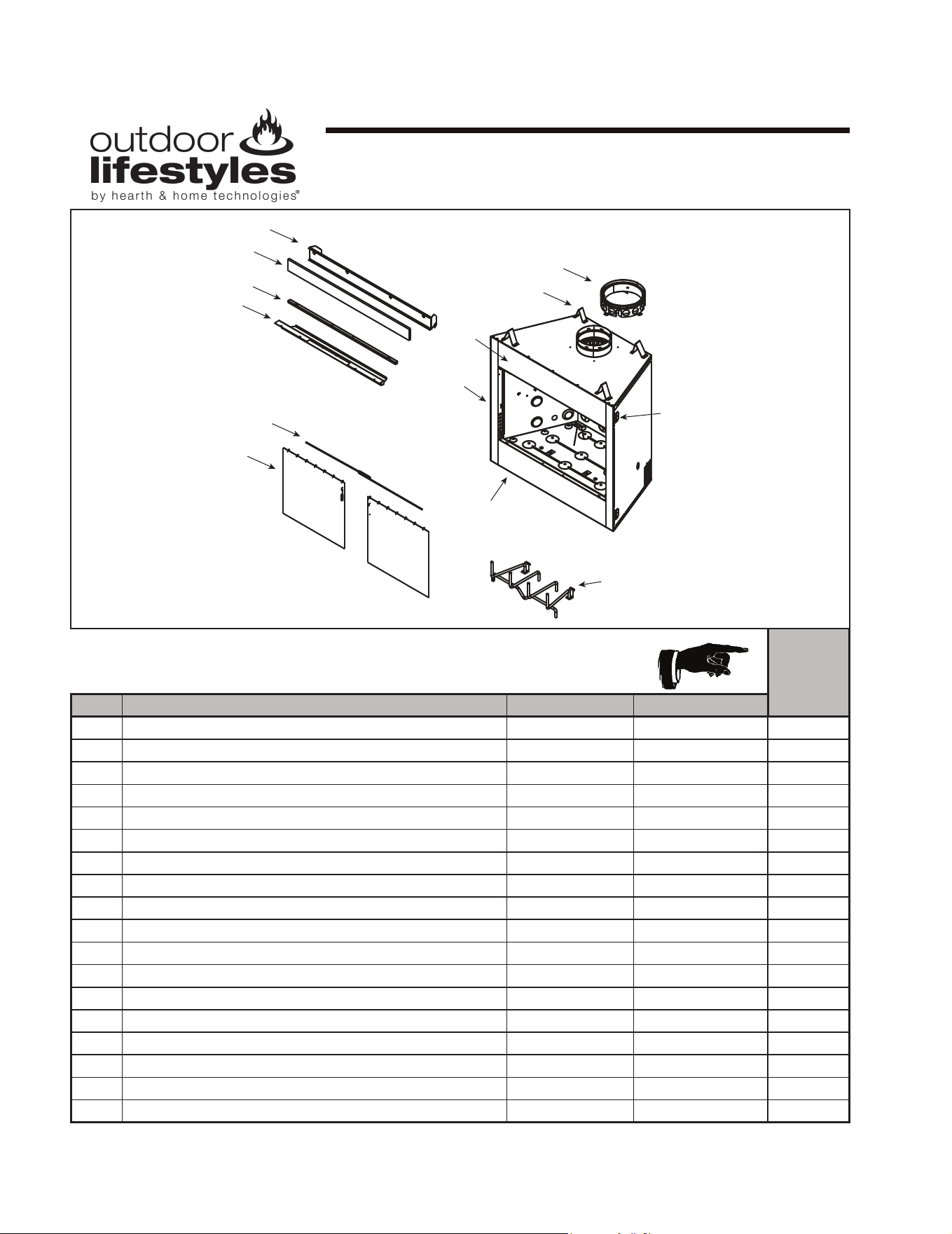
47
D. Service Parts
Outdoor Lifestyles by Hearth & Home Technologies • ODVILLA Wood Owners/Install • 4072-345 Rev B • 05/23
Service Parts
ODVILLA-36T-B, ODVILLA-36H-B
Beginning Manufacturing Date: Sept 2022
Ending Manufacturing Date: Active
IMPORTANT: THIS IS DATED INFORMATION. Parts must be ordered from a dealer or distributor.
Hearth and Home Technologies does not sell directly to consumers. Provide model
number and serial number when requesting service parts from your dealer or distributor.
Stocked
at Depot
ITEM DESCRIPTION COMMENTS PART NUMBER
1 Starter Section Assembly SRV22069 Y
2 Top Stando Qty 4 req SRV4044-111
3 Upper Front Face 4072-143
4 Non Combustible Front 4072-146
5 Door Track (used for upper) SRV4072-117
6 Smoke Shield 4072-135
7 Upper Face
Overlay
SRV4072-188
8 Left & Right Column
Overlay
SRV4072-176
9 Lower Face
Overlay
SRV4072-178
10 Firescreen Rod 1 piece 4072-133
11 Firescreen Assembly Qty 2 req SRV4072-019 Y
12 Grate, 21.50” F x 9.88” D x 14.88” B GR41 Y
13 Nailing Flange Qty 4 req SRV4044-161
Door Pivot Clip Qty 2 req SRV31527
Strip Protector SRV18320
Outside Air Hood Qty 2 req SRV33271
Extended Smoke Shield SRV4072-155
Installation Instructions and Owner’s Manual 4072-345
Additional service parts following page.
5/23
36” Outdoor Woodburning Fireplace
1
2
3
4
5
6
7
8
9
10
11
12
13
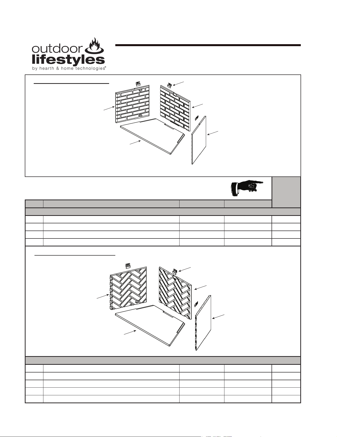
48
Outdoor Lifestyles by Hearth & Home Technologies • ODVILLA Wood Owners/Install • 4072-345 Rev B • 05/23
Service Parts
ODVILLA-36T-B, ODVILLA-36H-B
Beginning Manufacturing Date: Sept 2022
Ending Manufacturing Date: Active
IMPORTANT: THIS IS DATED INFORMATION. Parts must be ordered from a dealer or distributor.
Hearth and Home Technologies does not sell directly to consumers. Provide model
number and serial number when requesting service parts from your dealer or distributor.
Stocked
at Depot
ITEM DESCRIPTION COMMENTS PART NUMBER
Traditional Refractory
14.1
Side Refractory, 19.43” H x 18.21” W Qty 2 req SRV4044-220
14.2
Hearth Refractory, 35.85” F x 17.63” D x 20.91” B SRV4072-340
14.3
Back Refractory, 19.44” H x 20.91” W SRV4044-222
14.4
Retainer Qty 3 req SRV11847
Herringbone Refractory
15.1
Side Refractory, Left 19.43” H x 18.21” W SRV4048-205
15.2
Hearth Refractory, 35.85” F x 17.63” D x 20.91” B SRV4072-340
15.3
Side Refractory, Right 19.43” H x 18.21” W SRV4048-204
15.4
Back Refractory, 19.44” H x 20.91” W SRV4048-202
15.5
Retainer Qty 3 req SRV11847
#14 Traditional Refractory
#15 Herringbone Refractory
14.1
14.2
14.3
14.4
14.1
15.2
15.3
15.1
15.4
15.5
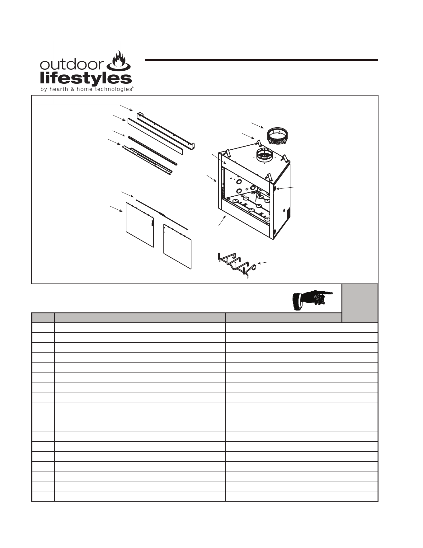
49Outdoor Lifestyles by Hearth & Home Technologies • ODVILLA Wood Owners/Install • 4072-345 Rev B • 05/23
Service Parts
ODVILLA-42T-B, ODVILLA-42H-B
Beginning Manufacturing Date: Sept 2022
Ending Manufacturing Date: Active
IMPORTANT: THIS IS DATED INFORMATION. Parts must be ordered from a dealer or distributor.
Hearth and Home Technologies does not sell directly to consumers. Provide model
number and serial number when requesting service parts from your dealer or distributor.
Stocked
at Depot
ITEM DESCRIPTION COMMENTS
PART NUMBER
1 Starter Section Assembly SRV22069 Y
2 Top Stando Qty 4 req SRV4044-111
3 Upper Front Face 4072-144
4 Non Combustible Front 4072-147
5 Door Track (used for upper) SRV4072-118
6 Smoke Shield 4072-136
7 Upper Face
Overlay
SRV4072-199
8 Left & Right Column
Overlay
SRV4072-176
9 Lower Face
Overlay
SRV4072-169
10 Firescreen Rod 1 piece 4072-134
11 Firescreen Assembly Qty 2 req SRV4072-020 Y
12 Grate, 21.50” F x 9.88” D x 20.88” B GR40 Y
13 Nailing Flange Qty 4 req SRV4044-161
Door Pivot Clip Qty 2 req SRV31527
Strip Protector SRV18320
Outside Air Hood Qty 2 req SRV33271 Y
Extended Smoke Shield SRV4072-156
Installation Instructions and Owner’s Manual 4072-345
Additional service parts following page.
5/23
42” Outdoor Woodburning Fireplace
1
2
3
4
5
6
7
8
9
10
11
12
13
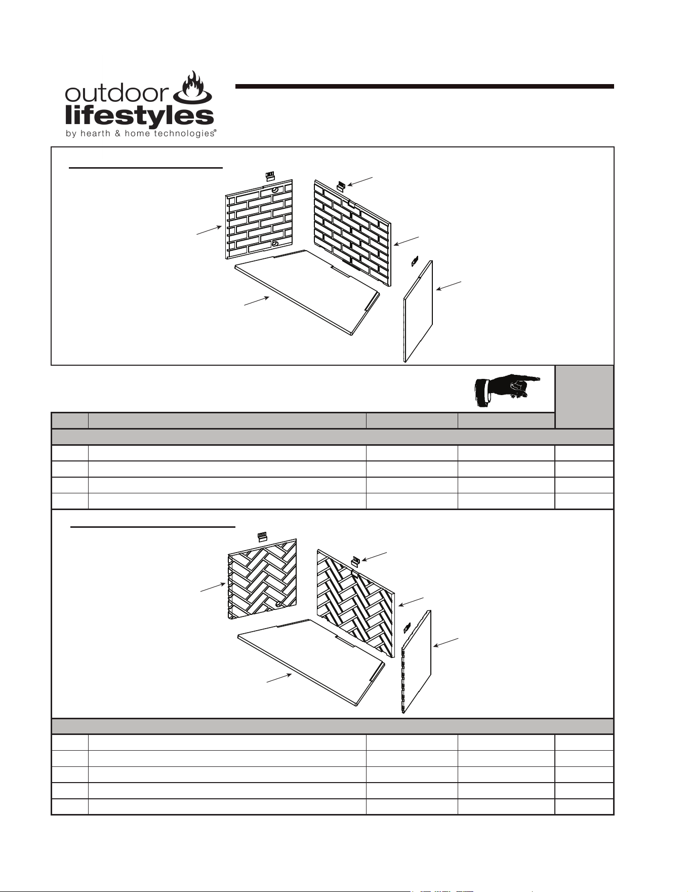
50
Outdoor Lifestyles by Hearth & Home Technologies • ODVILLA Wood Owners/Install • 4072-345 Rev B • 05/23
Service Parts
ODVILLA-42T-B, ODVILLA-42H-B
Beginning Manufacturing Date: Sept 2022
Ending Manufacturing Date: Active
IMPORTANT: THIS IS DATED INFORMATION. Parts must be ordered from a dealer or distributor.
Hearth and Home Technologies does not sell directly to consumers. Provide model
number and serial number when requesting service parts from your dealer or distributor.
Stocked
at Depot
ITEM DESCRIPTION COMMENTS PART NUMBER
Traditional Refractory
14.1 Side Refractory, 19.43” H x 17.86” W Qty 2 req
SRV4044-220
14.2 Hearth Refractory, 41.85” x 17.63” D x 26.91” B
SRV4072-341
14.3 Back Refractory, 19.44” H x 26.91” W
SRV4044-224
14.4 Retainer Qty 3 req SRV11847
Herringbone Refractory
15.1 Side Refractory, Left 19.43” H x 18.21” W SRV4048-205
15.2 Hearth Refractory, 41.85” x 17.63” D x 26.91” B SRV4072-341
15.3 Side Refractory, Right 19.43” H x 18.21” W SRV4048-204
15.4 Back Refractory, 19.44” H x 26.91” W SRV4048-203
15.5 Retainer Qty 3 req SRV11847
#14 Traditional Refractory
#15 Herringbone Refractory
14.1
14.2
14.3
14.4
14.1
15.2
15.3
15.1
15.4
15.5
51
– NOTES –
E. Contact Information
DO NOT DISCARD THIS MANUAL
CAUTION
• Important operating
and maintenance
instructions included.
• Leave this manual with
party responsible for
use and operation.
• Read, understand
and follow these
instructions for safe
installation and
operation.
DO NOT
DISCARD
Outdoor Lifestyles by Hearth & Home Technologies • ODVILLA Wood Owners/Install • 4072-345 Rev B • 05/23
Please contact your Outdoor Lifestyles dealer with any questions or concerns.
For the number of your nearest Outdoor Lifestyles dealer, please visit www.hearthnhome.com.