HI24040901 Rev. B
HUM INDUSTRIAL
STANDARD PROCEDURES
DWG NO: HI24040901 Rev. B
DATE: 04/22/2026
PAGE: 1 of 4
DESCRIPTION: Installation, Operation and Maintenance Manual
1. COMPANY INFORMATION:
1.1. ADDRESS:
1.1.1. 4220 Duncan Ave,
Suite 201
St. Louis, Missouri 63110
1.2. PHONE NUMBER: 314-750-8962
1.3. EMAIL: [email protected]
2. TITLE: Installation instructions of HUM sensor to 4415 series valves.
3. SCOPE: All 4415 series valves.
4. PURPOSE OF UNIT: Monitoring the Pneumatic Valve for Hopper Cars to verify the
valve is closed before the train moves or the hopper is refilled.
5. DISCUSSION:
5.1. TOOLS REQUIRED:
5.1.1. 9/64” Hex Wrench
5.1.2. 5/32” Hex Wrench
5.1.3. 3/16” Hex Wrench
5.1.4. HUM Sensor Kit
5.2. MAGNET INSTALLATION:
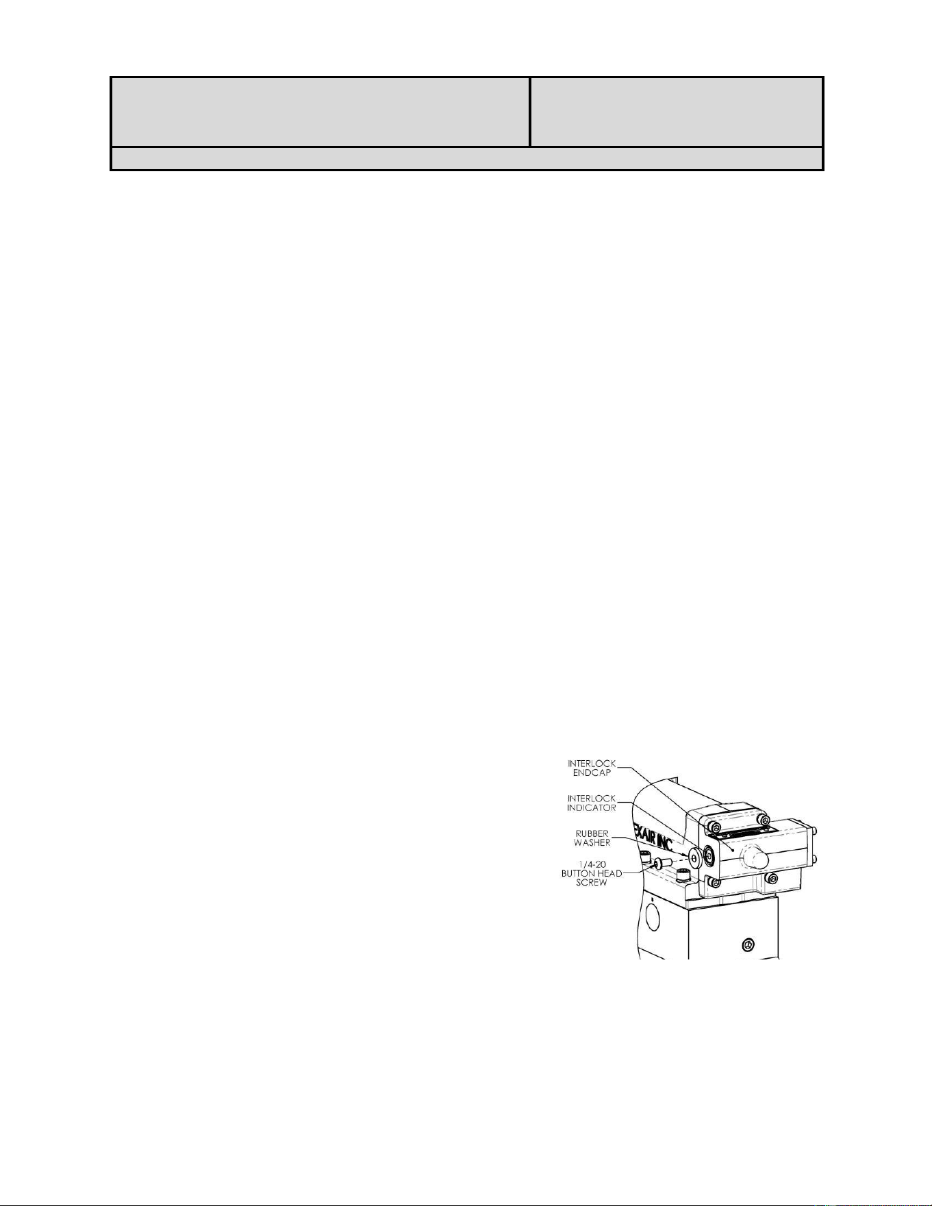
5.2.1. Locate the INTERLOCK ENDCAP.
Shown in Figure 1.
5.2.2. Using 5/32” hex wrench, remove the ¼-20
BUTTON HEAD SCREW and RUBBER
WASHER from the end of the INTERLOCK
INDICATOR.
5.2.3. Discard both.
Figure 1
HI24040901 Rev. B
HUM INDUSTRIAL
STANDARD PROCEDURES
DWG NO: HI24040901 Rev. B
DATE: 04/22/2026
PAGE: 2 of 4
DESCRIPTION: Installation, Operation and Maintenance Manual
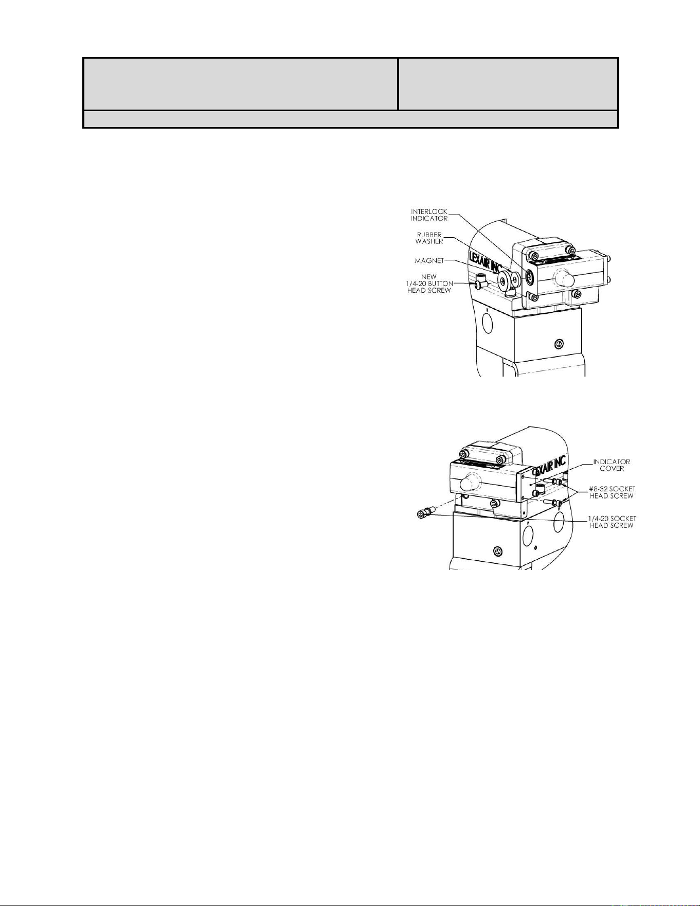
5.2.4. Using the new parts provided in the kit
insert the new BUTTON HEAD SCREW
through the center hole of the MAGNET and the new RUBBER WASHER as
shown in Figure 2.
5.2.5. Thread the assembly onto the end of the
INTERLOCK INDICATOR and tighten.
5.3. SENSOR INSTALLATION
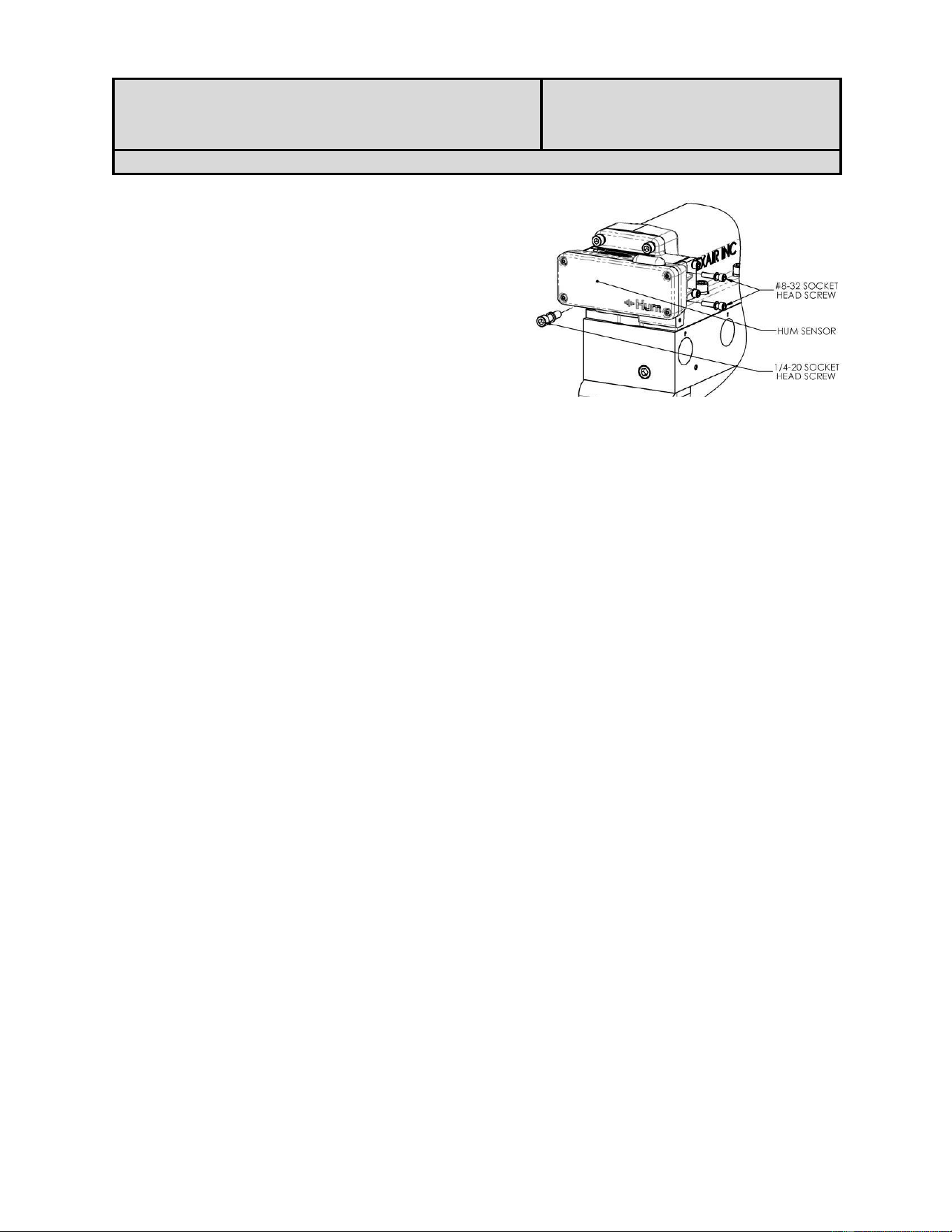
5.3.1. Locate the INDICATOR COVER on
the opposite side from the
INDICATOR. See Figure 3.
5.3.2. Using the 9/64” hex wrench, remove
the two rear most #8-32 SOCKET
HEAD SCREWS with the associated
lock washers and retain for subsequent
assembly.
5.3.3. Using the 3/16” hex wrench, remove
the lower left ¼-20 SOCKET HEAD
SCREW with associated lock washer and retain for subsequent assembly.
FIGURE 2
Figure 3
HI24040901 Rev. B
HUM INDUSTRIAL
STANDARD PROCEDURES
DWG NO: HI24040901 Rev. B
DATE: 04/22/2026
PAGE: 3 of 4
DESCRIPTION: Installation, Operation and Maintenance Manual
5.3.4. Install the HUM SENSOR to the
end of the of the INTERLOCK END
CAP as shown in Figure 4.
5.3.5. Loosely install the previously
removed ¼-20 and #8-32 SOCKET
HEAD SCREWS with lock washers.
5.3.6. Once in place tighten all three
SOCKET HEAD SCREWS.
6. TECHINCAL DETAILS
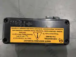
6.1. DEVICE LABEL DETAILS:
Hum Industrial Model # HI24030101
Class I, Div. 2 Groups A,B,C,D
Temperature Code: T6
T
amb
: -20°C to 40°C
Electrical Rating: 100mA @ 3.0v
IP64 Rated
Explosion Hazard: Do Not Open Device. No user replaceable or serviceable parts.
Avertissement: Risque D'explosion. Ne Pas Ouvrir. Aucune pièce remplaçable ou réparable
6.2. BATTERY REPLACEMENT INSTRUCTIONS: This device is not intended for on-site
battery replacement. Any opening or tampering of the device will result in the void of all
warranties. For device service, please contact HUM INDUSTIAL.
6.3. OPERATING INSTRUCTIONS: Once installed the device will start working
automatically.
6.4. MAINTENANCE INSTRUCTIONS: The device does not require any maintenance, if
there are any issues with the device, please contact Hum Industrial for service.
6.5. ENVIORNMENTAL SPECIFICATIONS:
Maximum Humidity: 100%
Maximum Altitude: 12,000 feet
Pollution Degree: 4 (Electrical Equipment for Outdoor Use)
Note: This device is designed to be used in outdoor locations, to withstand normal weather
conditions, including wet locations.
6.6 WARNINGS:
The intended function of this device could be impaired if the equipment is used in a
manner not specified by the manufacturer.
Figure 4
HI24040901 Rev. B
HUM INDUSTRIAL
STANDARD PROCEDURES
DWG NO: HI24040901 Rev. B
DATE: 04/22/2026
PAGE: 4 of 4
DESCRIPTION: Installation, Operation and Maintenance Manual
6.7 WIRELESS REGULATORY INFORMATION
6.7.1 FCC ID
FCC ID: 2BUPV-VS01
IC: 35176-VS01
6.7.2 FCC Compliance Statement
Changes or modifications not expressly approved by Hum Industrial
Technology Inc. could void the user's authority to operate the equipment.
This device complies with Part 15 of FCC Rules. Operation is subject to the
following two conditions: (1) this device may not cause harmful interference, and
(2) this device must accept any interference received, including interference that
may cause undesired operation.
Note: This equipment has been tested and found to comply with the limits for a Class A
digital device, pursuant to part 15 of the FCC Rules. These limits are designed to provide
reasonable protection against harmful interference when the equipment is operated in a
commercial environment. This equipment generates, uses, and can radiate radio frequency
energy and, if not installed and used in accordance with the instruction manual, may cause
harmful interference to radio communications. Operation of this equipment in a residential
area is likely to cause harmful interference in which case the user will be required to
correct the interference at his own expense.
6.7.3 ISED Canada Compliance Statement
This device contains licence-exempt transmitter(s)/receiver(s) that comply with
Innovation, Science and Economic Development Canada’s licence-exempt RSS(s).
Operation is subject to the following two conditions: 1.This device may not cause
interference. 2. This device must accept any interference, including interference
that may cause undesired operation of the device.
L’émetteur/récepteur exempt de licence contenu dans le présent appareil est
conforme aux CNR d’Innovation, Sciences et Développement économique Canada
applicables aux appareils radio exempts de licence. L’exploitation est autorisée aux
deux conditions suivantes : 1. L’appareil ne doit pas produire de brouillage; 2.
L’appareil doit accepter tout brouillage radioélectrique subi, même si le brouillage
est susceptible d’en compromettre le fonctionnement.
7. REVISION HISTORY:
REV DATE DISCRIPTION CHKD APRVD
A 03/15/2025 Document
created DAL LC
B 04/22/2026 ADDED SECTION 6.7 LC