Installation & User Guide
Valve Controller 2
YS5003(S)-UC
KITS:
YS5003(S)-UC & BULLDOG
YS5003(S)-UC & DN##
Revision Mar. 15, 2023

. Welcome!
. Before You Begin
. What's Included
. Required Items
. Get to Know Your Valve Controller 2
. Power Up
. Install the App
. Add Your Valve Controller 2 to the App
. Install the Valve Controller 2
. Get to Know Your Bulldog Valve Robot
. Install the Bulldog Valve Robot
. Final Connections
. Manual Operation
. Testing
. Troubleshooting
. Get to Know Your Motorized Valve
. Install the Motorized Valve
. Final Connections
. Manual Operation
. Testing
. Troubleshooting
. Control-D2D Device-to-Device Pairing
. Using the App & 3rd-Party Services
. Factory Reset
. Firmware Update
. Battery Replacement
. Warnings
. Warranty
. FCC Statement
. IC Statement
. Contact Us
A
B
C
D
E
F
G
H
I
J
K
L
M
N
O
P
Q
R
S
T
U
V
W
X
Y
Z
AA
AB
AC
AD
AE
01
02
03
05
07
08
09
10
12
15
16
22
23
24
25
28
29
33
34
35
36
38
41
41
42
43
45
47
48
50
51
TABLE OF CONTENTS

01
Welcome!
Thank you for purchasing YoLink products! We
appreciate you trusting YoLink for your smart
home & automation needs. Your 100%
satisfaction is our goal. If you experience any
problems with your installation, with our
products or if you have any questions that this
manual does not answer, please contact us right
away. See the Contact Us section for more info.
Thank you!
Eric Vanzo
Customer Experience Manager
A
User Guide Conventions
The following icons are used in this guide to
convey specific types of information:
Very important information
(can save you time!)
Good to know info but may not
apply to you
02
Download the most current version of the user
guide by scanning the QR code:
Your Valve Controller 2 wirelessly connects to
the internet via a YoLink Hub or SpeakerHub, and
it does not directly connect to your WiFi or local
network. In order for remote access to the device
.from the app, and for full-functionality, a YoLink
hub is required. This guide assumes the YoLink
app has been installed on your phone, and a
YoLink Hub or SpeakerHub is installed and
online.
Before You Begin
Visit our Valve Controller 2 support page on our
website, for the latest installation guides,
additional resources, information and videos by
visiting:
www.shop.yosmart.com/pages/valve-
controller-2-product-support
Or by scanning the QR code:
B
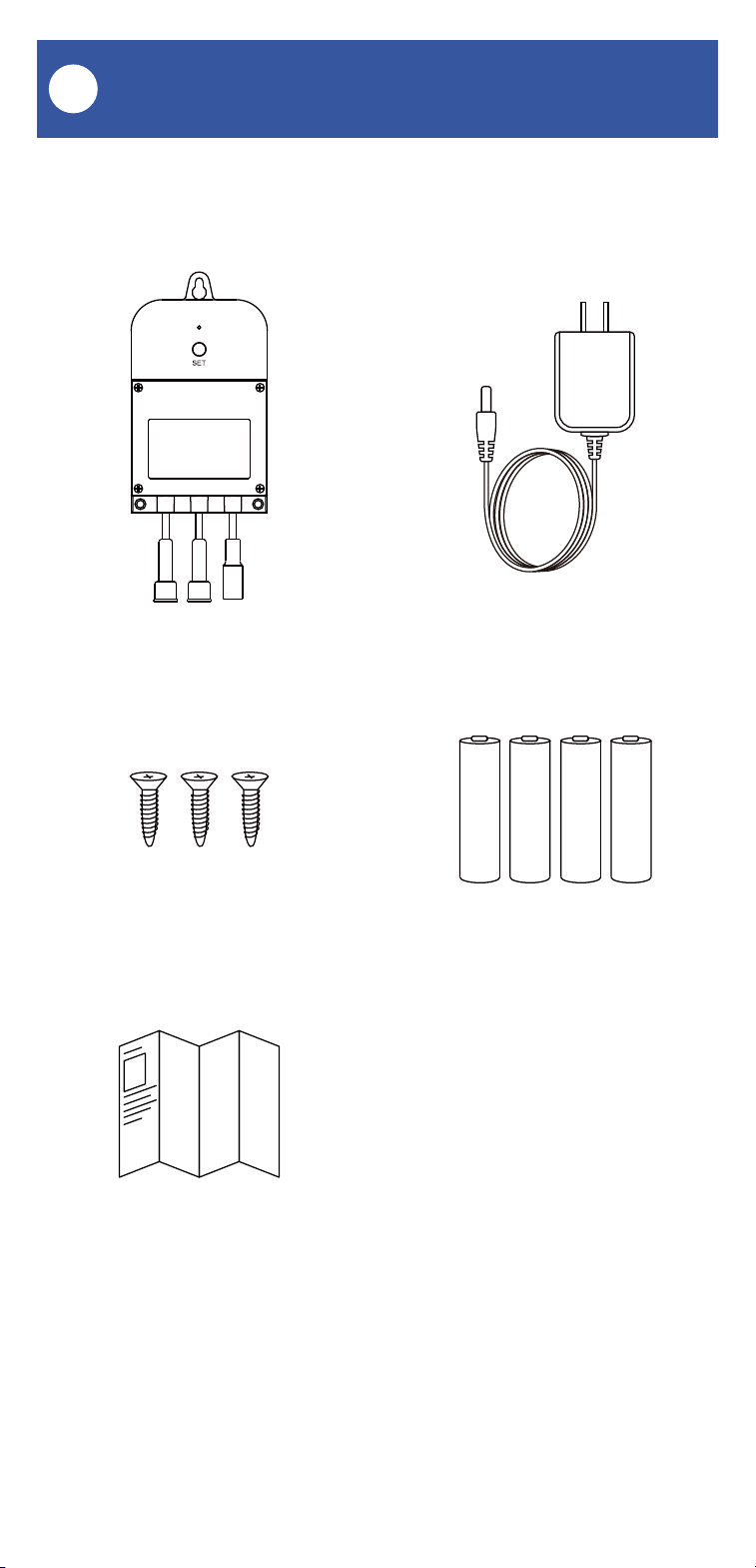
03
What's Included
C
Valve Controller 2 Plug-in Power Supply
4 x AA Batteries (Pre-Installed)Phillips Head Screws(3)
Quick Start Guide
YS5003(S) Items:
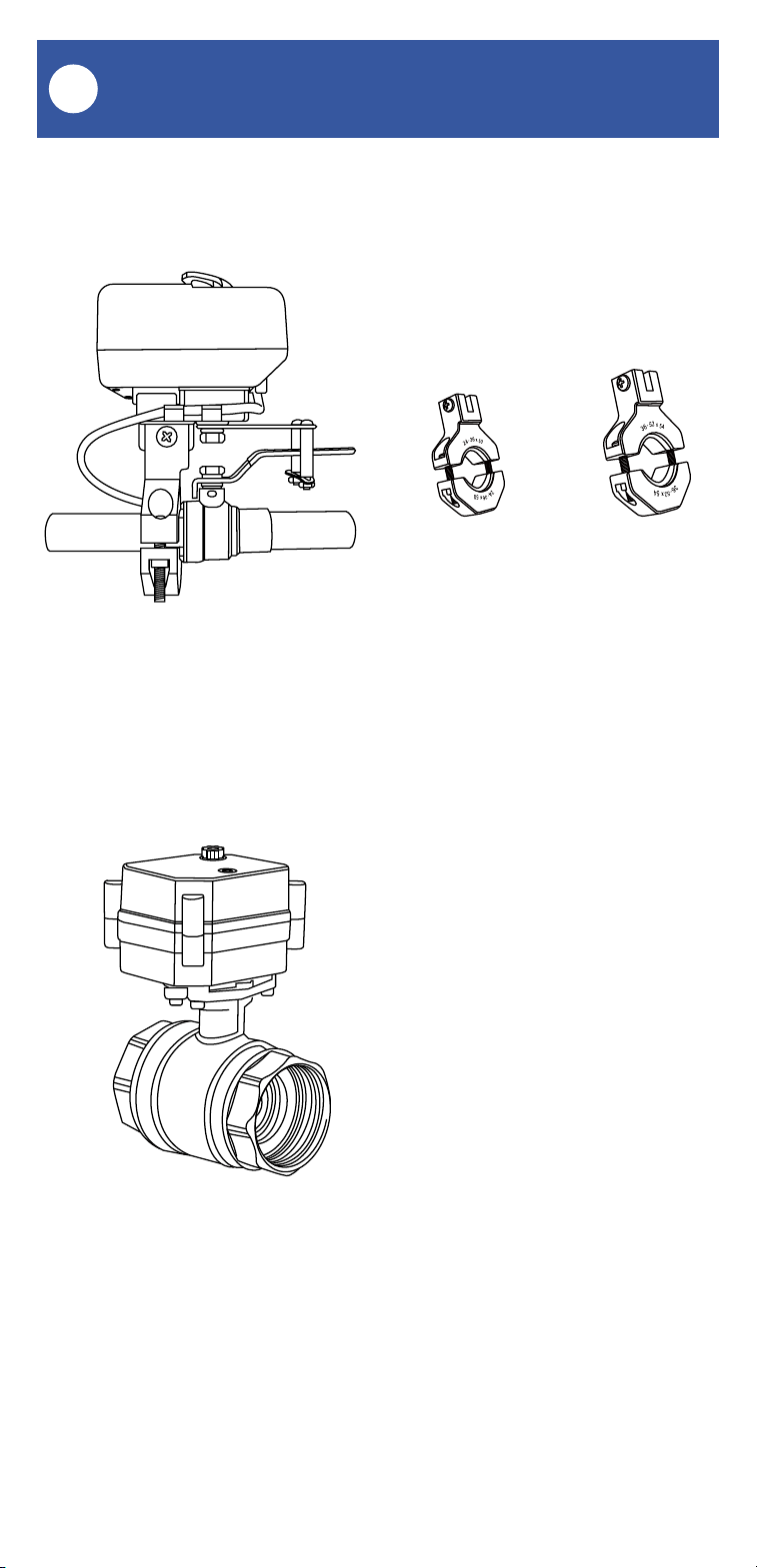
04
Bulldog Valve Robot Large & Small Brackets
24-36x50 36-52x54
Motorized Valve
What's Included, Continued
C
Bulldog Valve Robot Kit Items:
Motorized Valve Kit Items:
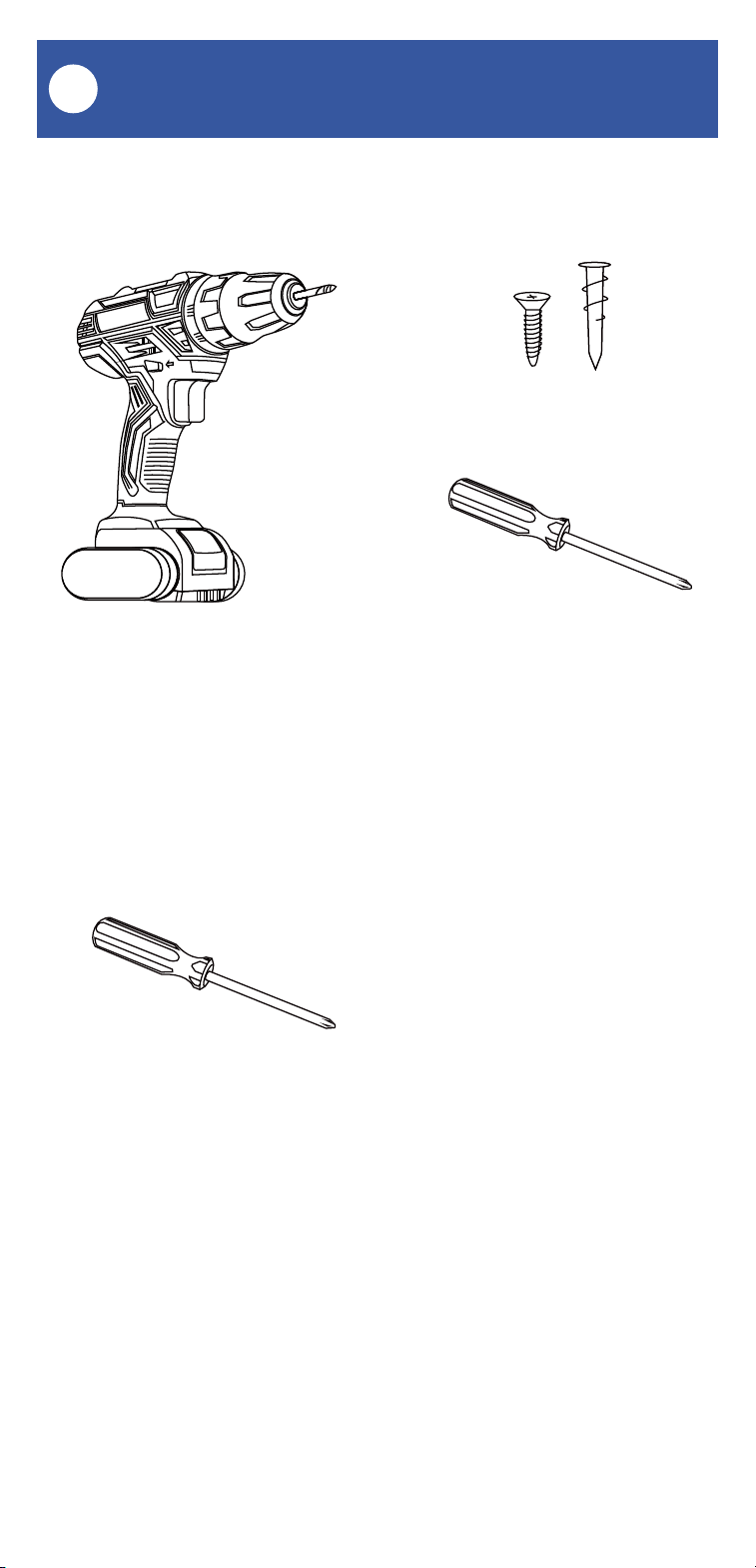
05
These tools or items may be required:
Required Items
D
Wall Anchors
Drill with Drill Bits Medium Phillips Screwdriver
Medium Phillips Screwdriver
These items will be required to install the
Bulldog Valve Robot:
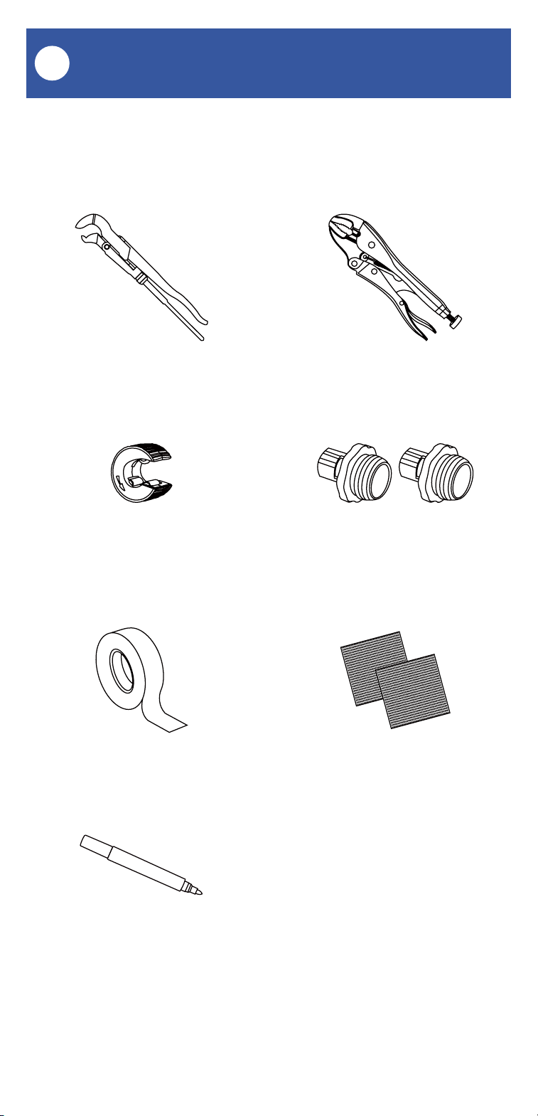
06
Locking PliersPipe Wrench
Copper Pipe Cutting Tool
SandpaperThread Seal Tape
Marker or Pencil
Pipe Fittings/Adapters
These items may be required to install the
motorized valve:
Required Items, Continued
D
07
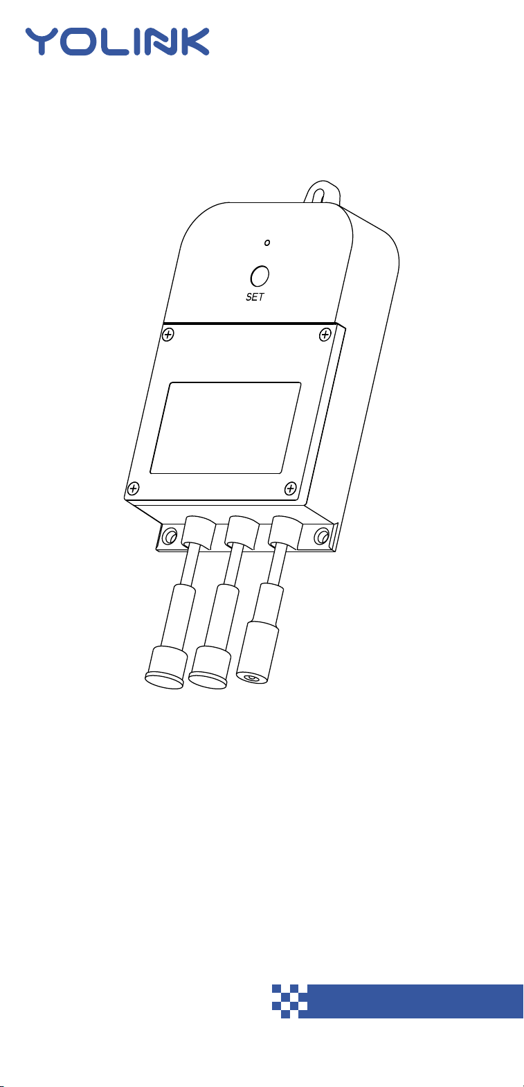
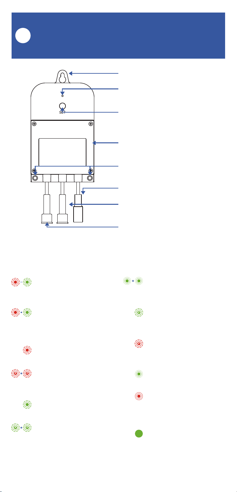
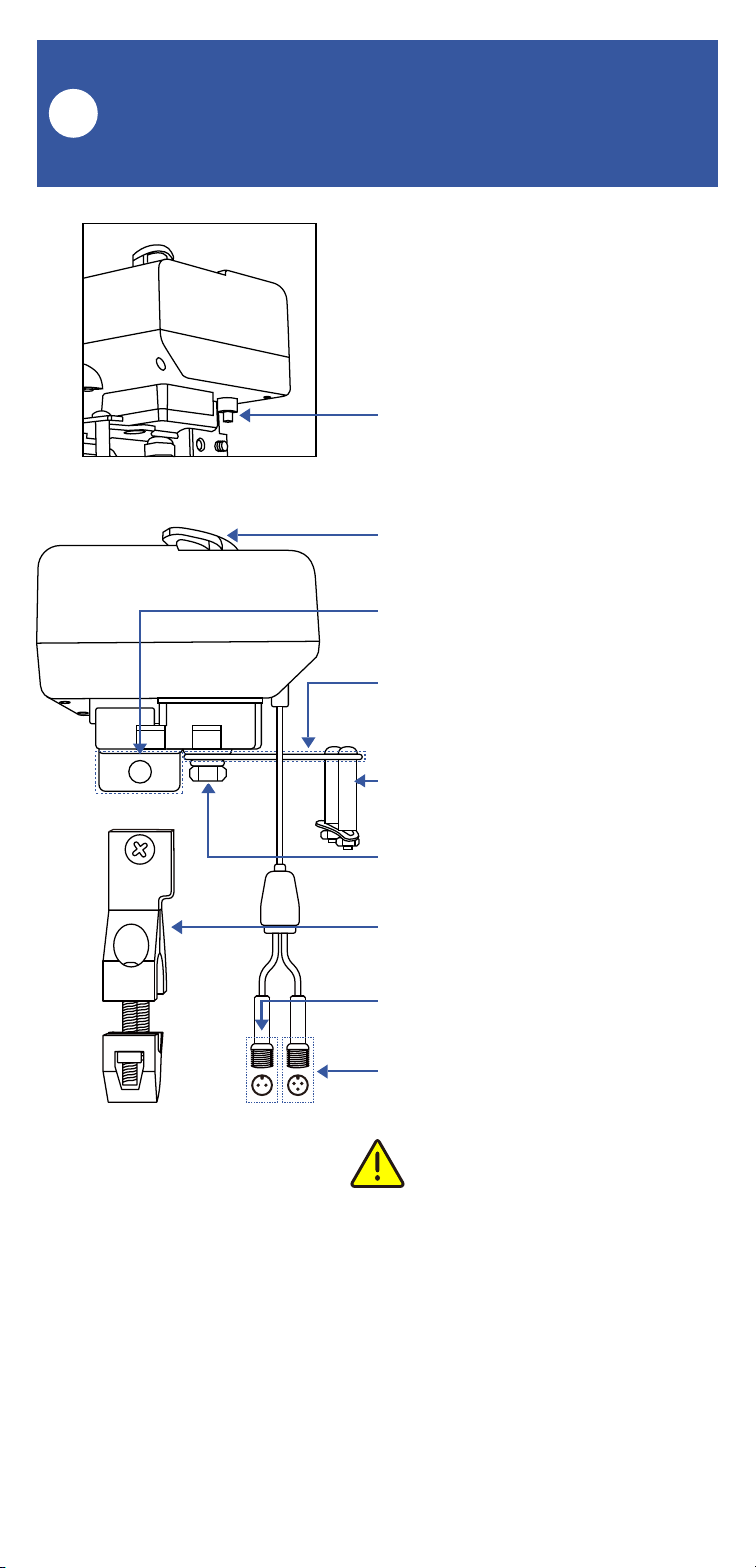
Get to Know Your Valve
Controller 2
E
Keyhole Mounting Slot
Status LED
(See LED Behaviors, Below)
SET Button
Battery Housing Cover
Mounting Hole
12VDC Input Cable
Valve Status Cable
(YS5003S, Only)
Valve Control Cable
LED Behaviors
Blinking Red Once,
Then Green Once
Device Start-Up
Blinking Red And Green
Alternately
Restoring to Factory
Defaults
Blinking Red Once
Valve Closing
Quick Blinking Red
Twice
Valve is Closed
(YS5003S, Only)
Blinking Green Once
Valve Opening
Quick Blinking Green
Twice
Valve is Open
(YS5003S, Only)
Slow Blinking Green
Twice
Connecting to Hub
Quick Blinking Green
Control-D2D Pairing in
Progress
Quick Blinking Red
Control-D2D Unpairing
in Progress
Slow Blinking Green
Updating
Fast Blinking Red Every
30 Seconds
Low Battery, Replace
Batteries Soon
Green LED on Steady�
12VDC Power Input
Connected
08
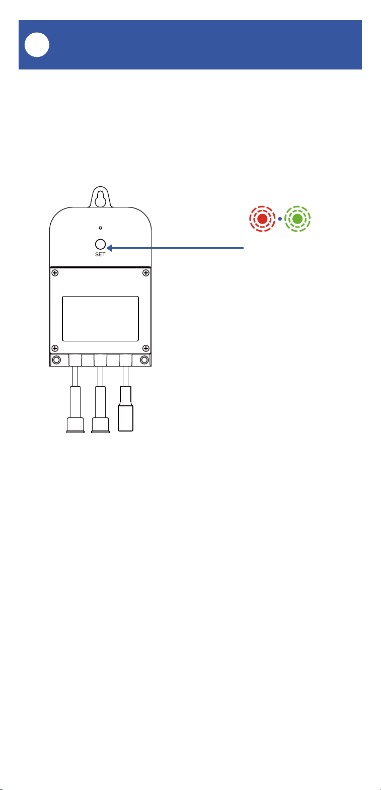
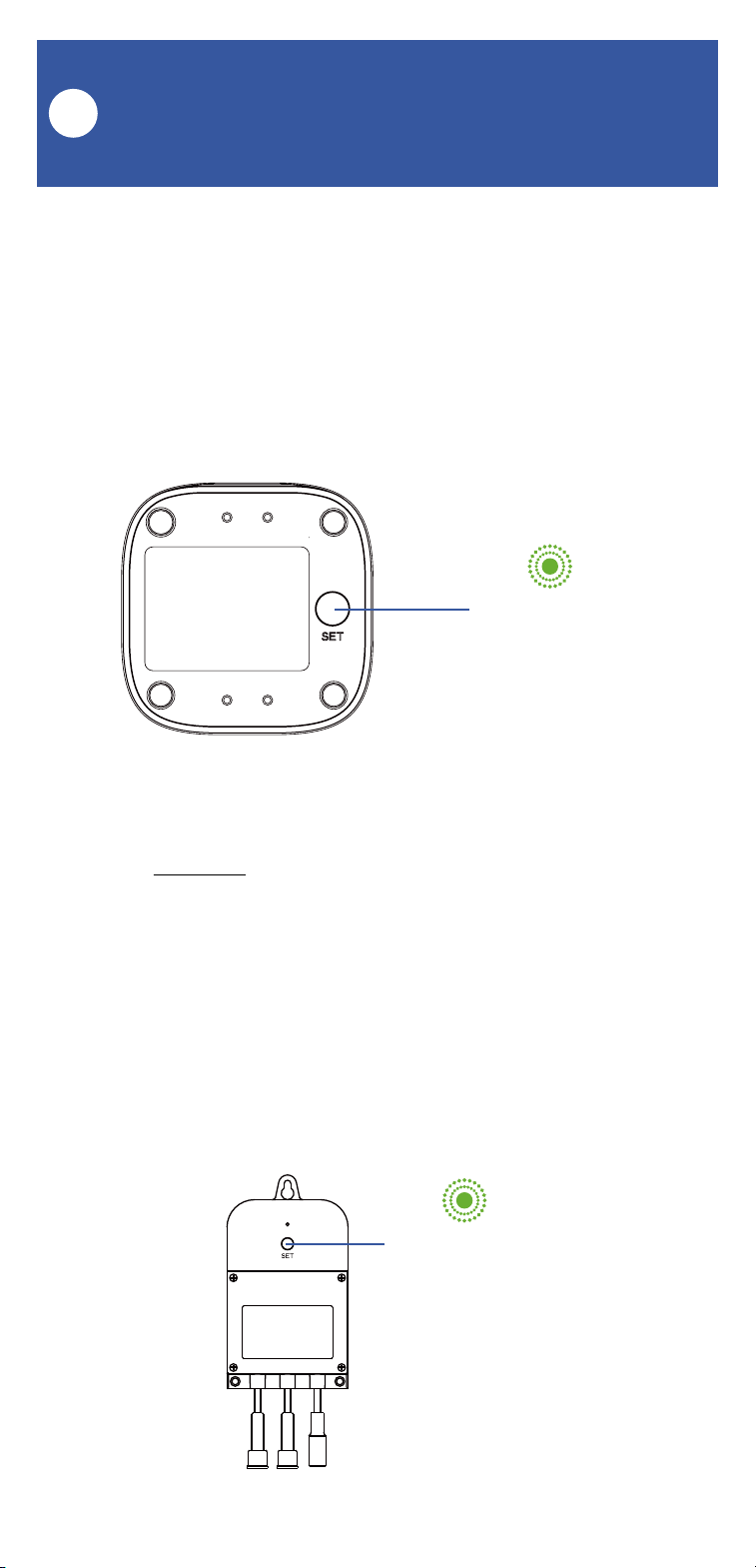
Power Up
F
Power up the Valve Controller 2 by briefly
pressing the SET button, until the LED flashes
(red, then green).
SET button

09
Install the App
G
Open the app and tap Sign up for an account.
You will be required to provide a username and a
password. Follow the instructions, to set up a
new account. Allow notifications, when
prompted.
You will immediately receive a welcome email
from no-r[email protected] with some helpful
information. Please mark the yosmart.com
domain as safe, to ensure you receive important
messages in the future.
Log in to the app using your new username and
password.
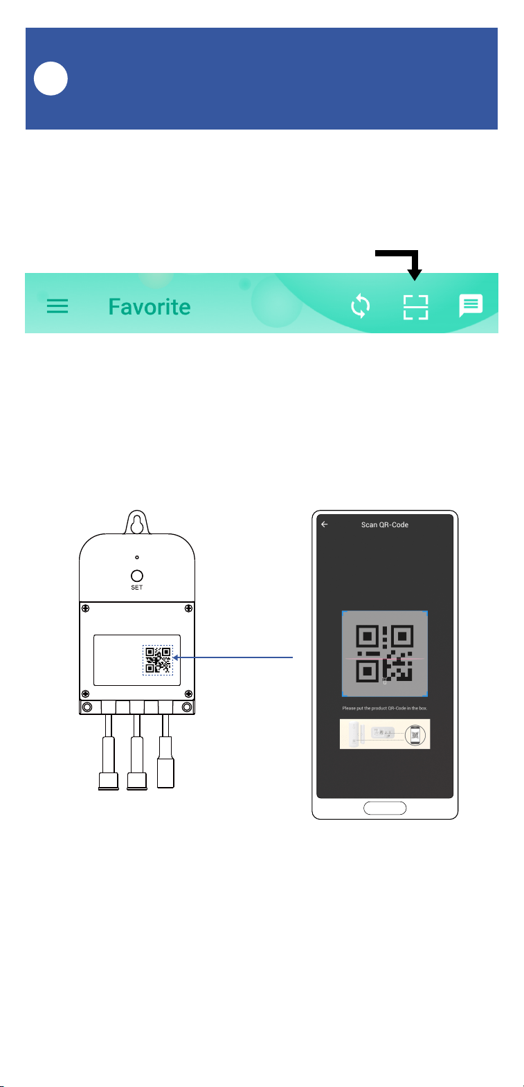
The app opens to the Favorite screen. This is
where your favorite devices and scenes will be
shown. You can organize your devices by room,
in the Rooms screen, later.
If you are new to YoLink, please install the app
on your phone or tablet, if you have not already.
Otherwise, please proceed to the next section.
Scan the appropriate QR code below or find the
“YoLink app” on the appropriate app store.
Apple phone/tablet
iOS 9.0 or higher
Android phone/tablet
4.4 or higher
10
1. Tap Add Device (if shown) or tap the scanner
icon:
Scanner icon
2. Approve access to your phone’s camera, if
requested. A viewfinder will be shown on the
app.
3. Hold the phone over the QR code so that the
code appears in the viewfinder. If successful, the
Add Device screen will be displayed.
Add Your Valve Controller 2
to the App
H
11
Add Your Valve Controller 2 to
the App, Continued
H
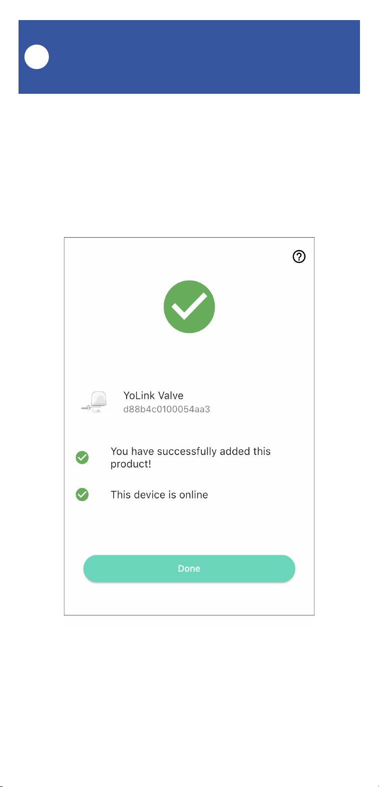
4. You can change the device name and assign it
to a room later. Tap Bind device.
5. If successful, the screen will appear as shown.
Tap Done.

12
Install the Valve Controller 2
I
Preparing for installation:
Determine where you will mount the valve
controller. The Valve Controller 2 was designed
to be wall-mounted, at an indoor or outdoor
location.
If installing your Valve Controller 2 and/or valve
device at an outdoor location, please first refer to
the environmental range specifications, found on
the Valve Controller 2 product support page of
our website. Also, while the Valve Controller 2,
the Bulldog Valve Controller and our motorized
valves are rated for outdoor use, to ensure years
of dependable operation, provide protection from
rain and direct sunlight with overhead cover, in
the form of an enclosure or rain hood.�
Do not install your valve controller or valve
device at a location where it will be submerged
in water.
Use of the 12VDC power supply/adapter is
optional. If you do not use the power
supply/adapter (or provide your own 12VDC
power supply), the valve controller must have
batteries installed. If you do connect a 12VDC
power supply to your valve controller, the use of
batteries is optional.

13
Install the Valve Controller 2,
Continued
I
With the use of optional extension cables, the
valve controller can be installed remotely from
the Bulldog or motorized valve. In some cases
this may allow placing the controller at a more
convenient or more accessible location (for
battery replacement, etc.). The location of the
valve controller must be within the limits of the
cables. If in doubt, connect all applicable cables
between the controller and the valve device and
the AC power outlet (if applicable) and choose
an appropriate location for the controller.
(Extension cables can be purchased on our
website.)
Determine how you will mount the valve
controller to the wall, and ensure you have the
appropriate mounting hardware (screws,
anchors, etc.) for the wall surface.
Install the Valve Controller 2:
1. Holding the valve controller at the desired
location, and using a marker or pencil, transfer
the valve controller’s top mounting hole location
to the wall surface.
2. If using wall anchors, install one at the top
mounting hole location, per the manufacturer’s
instructions (drill a pilot hole first, etc.)

14
3. Insert a screw in the top mounting hole
location, but do not screw it flush with the wall;
leave space on the end of the screw for the valve
controller.
4. Hang the valve controller on this screw, and it
should be level on the wall. Optionally, you can
verify the valve controller is level with a level tool
at this time. Using a marker or pencil, transfer
the valve controller’s two bottom mounting
holes to the wall surface.
5. If using wall anchors, install them at this time.
6. Insert screws in each of the two bottom
mounting hole locations.
7. Tighten all three screws, and confirm the valve
controller is secured to the wall surface.
To install a motorized valve, go to page 28. To
install a Bulldog Valve Robot, proceed to the next
page.
Install the Valve Controller 2,
Continued
I
15
Get to Know Your Bulldog
Valve Robot
J
Clutch Pin
Handle and Position Indicator
Mounting Tab
Rocker Arm
Handle-Supporting Bolt
Output Shaft of Bulldog
Brackets
Valve Control Cable
Valve Status Cable
(YS5003S Only)
Please note: the existing ball valve must be in
good working order. It must open and close
smoothly, with minimal effort, and it must close
fully, shutting off the water completely. The
Bulldog Valve Robot is not able to correct
mechanical issues of the ball valve.
16
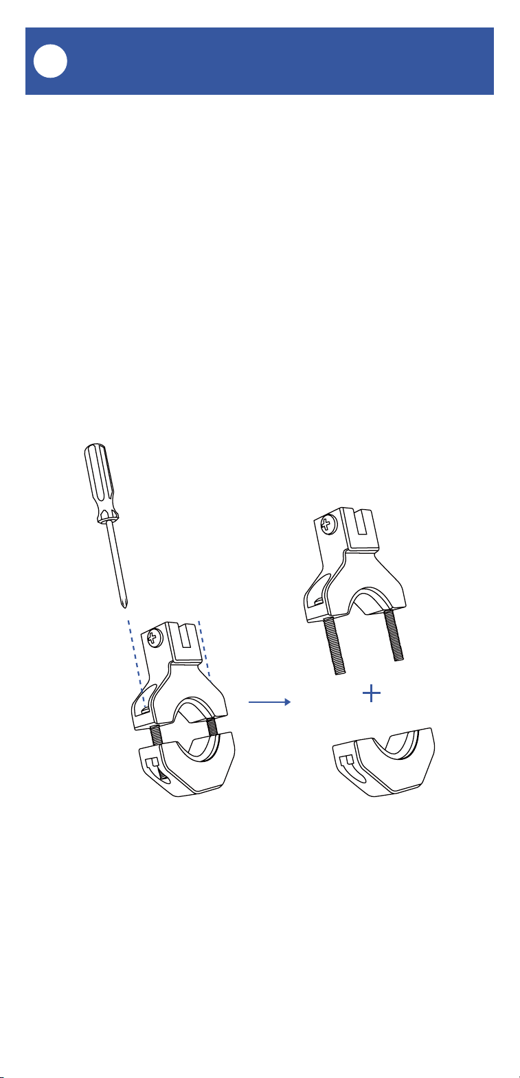
Install the Bulldog Valve Robot
K
1. Select the appropriate bracket for your
application. The appropriate bracket fits over the
ball valve (where it is connected to the pipe) and
can subsequently be tightened securely to the
ball valve. If the bracket does not fit over the ball
valve, or seems to be too loose, try the other
bracket.
2. Loosen the two screws on the bracket, to
allow for separating it into two pieces, as shown.
17
Install the Bulldog Valve Robot,
Continued
K
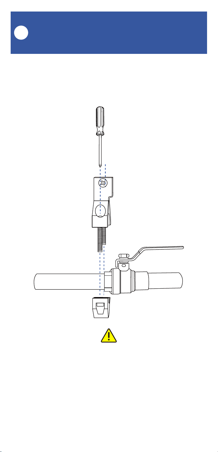
3. Place the upper bracket and lower bracket on
the valve, as shown, and loosely tighten the
screws.
Important! The bracket must be mounted to the
ball valve, not to the pipe. The ball valve should
have at least one side shaped like a nut or bolt
head. The brackets will not tighten to pipe or to a
round portion of the ball valve.
18
Install the Bulldog Valve Robot,
Continued
K
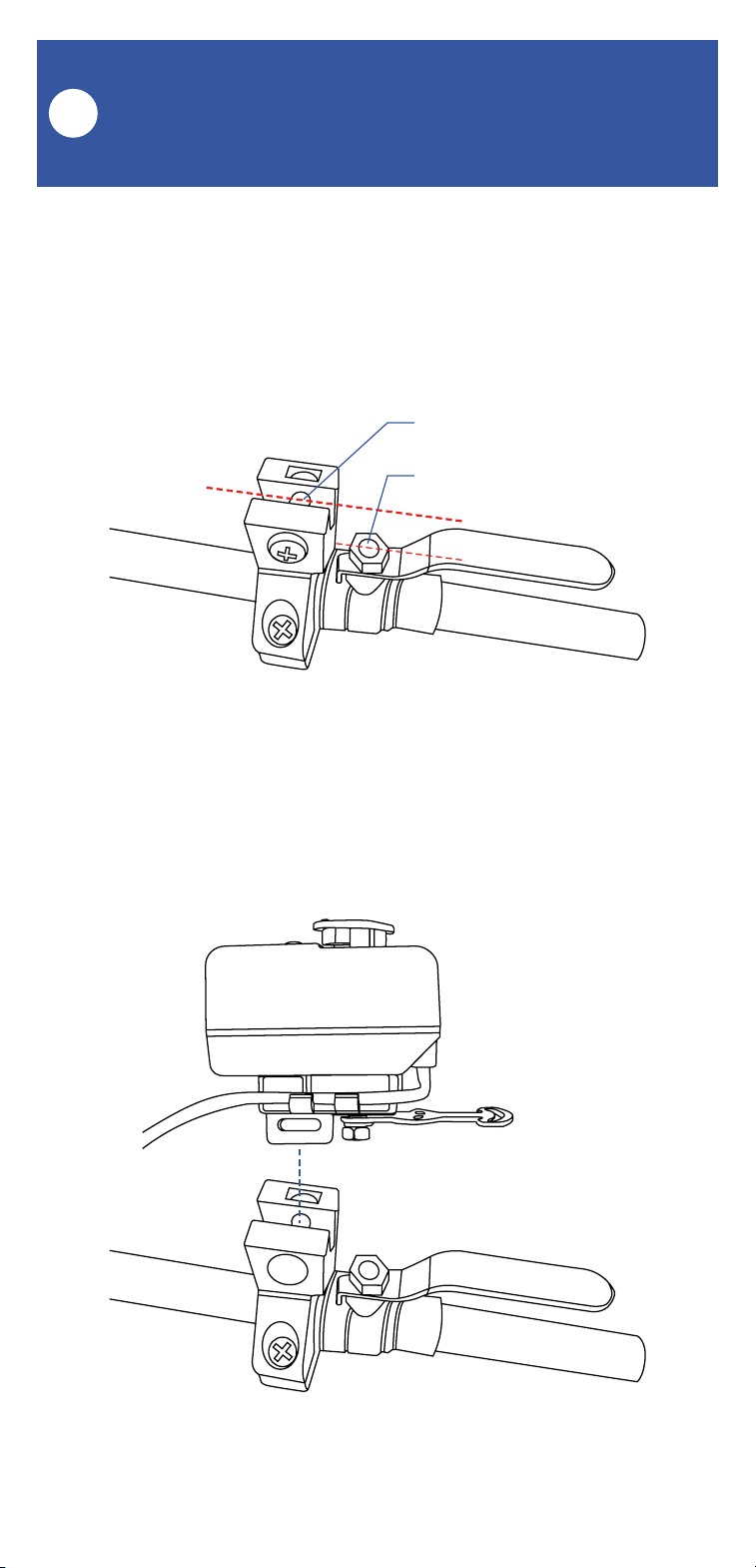
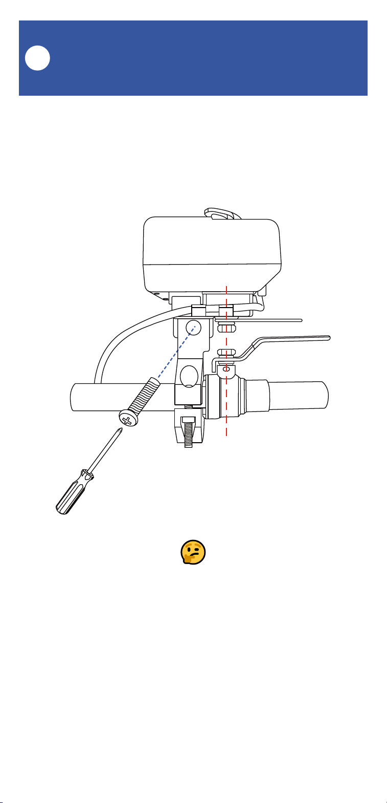
4. Position the bracket so that it is aligned with
the pivot point of the ball valve, by visualizing a
line between the tab slot and the pivot point, as
shown.
5. Remove the screw from the tab slot, then
attach the Valve Robot to the bracket.
Pivot Point
Tab Slot
19
Install the Bulldog Valve Robot,
Continued
K
6. Keeping the center axis of the Valve Robot’s
motor shaft aligned with the ball valve shaft, as
indicated by the red dashed line, reinsert and
tighten the tab slot screw.
If it is not possible to align the parts as shown,
or if the bracket can not be secured to the ball
valve, consider rotating the ball valve handle
180°. After removing the Bulldog, this can be
done by removing the ball valve handle, and then
reinstalling it on the other side. Reinstall the
Bulldog (on the other side of the ball valve) and
check if alignment is better in this position.
20
Install the Bulldog Valve Robot,
Continued
K
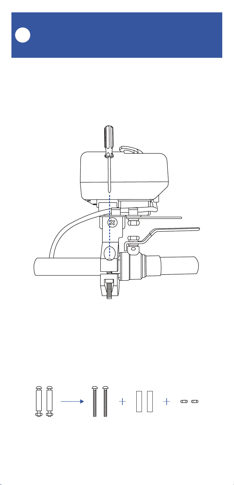
7. Securely tighten the two screws on the brack-
et. Gently tug on the Bulldog, and tighten the
screws until the Bulldog is firmly held in place by
the bracket and tab screw.
8. Remove the nuts and collars from the two
handle supporting bolts, as shown.
21
Install the Bulldog Valve Robot,
Continued
K
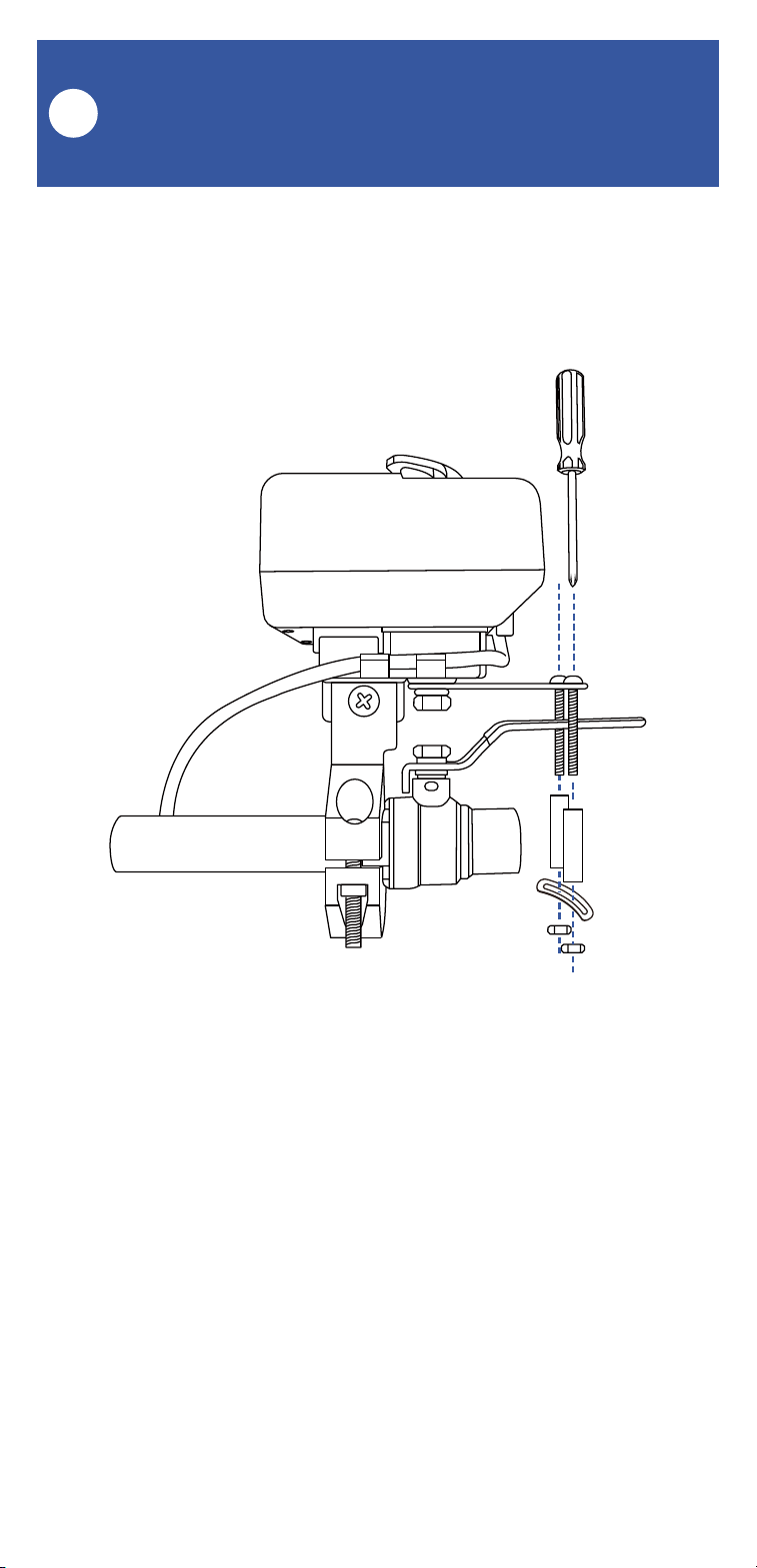
9. Place the bolts in the slot on the rocker arm,
with one on each side of the valve handle, as
shown.
10. Put the collars back on the bolts. Holding
them in place with one hand, insert the bottom
supporting bracket over the end of each bolt, as
shown. Insert and loosely tighten a nut on each
bolt. Now, position each bolt/collar so that it is
snug against the valve lever handle, with one on
each side of the handle. Using a Phillips
screwdriver, tighten the screw on each
bolt/collar assembly, holding the nut in place, as
needed. Confirm that each collar is snug against
the handle.

22
1. Connect the valve controller’s valve control
cable (2-pin) to the control cable of the Bulldog
Valve Robot. Ensure the arrow of the cable
connector aligns with the arrow of the other
cable connector. Twist the collar of the
connector tight.
2. YS5003S, only: Connect the valve controller’s
valve status cable (3-pin) to the valve status
cable of the Bulldog Valve Robot. Ensure the
arrow of the cable connector aligns with the
arrow of the other cable connector. Twist the
collar of the connector tight.
3. If using the 12VDC power input, via the
included plug-in power adapter or via your own
12VDC power supply, prior to plugging-in the
power supply/adapter or energizing the power
supply circuit, connect the valve controller’s
12VDC input cable to the power adapter or
12VDC power supply cable. Plug in the power
supply/adapter or energize the 12VDC power
supply circuit at this time. If you are electing to
power the valve controller only from the 12VDC
power input (not recommended), you can
remove the batteries at this time.
Final Connections
L
Use care to not connect a 2-pin connector to a
3-pin connector or vice versa. Never force two
connectors together – the connectors should
mate-up easily and not require force to tighten.
23
It is recommended to always use the app or the
valve controller SET button to operate the
Bulldog Valve Robot. If you need to manually
operate the Bulldog without using the app, you
can press the SET button on the valve controller.
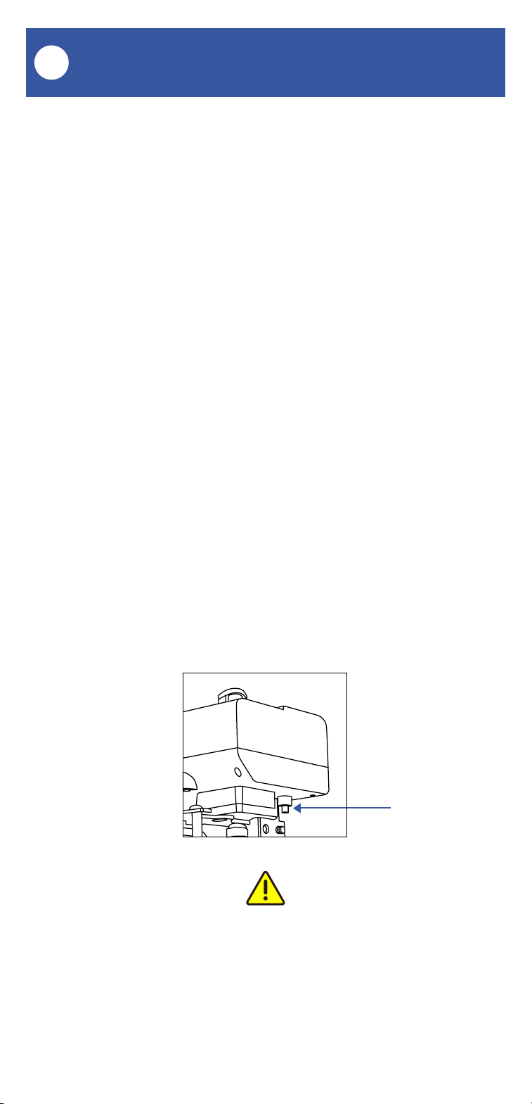
If you need to operate the Bulldog Valve Robot
without using the valve controller, you can do so
by depressing the clutch pin as shown below.
While depressing this pin, the motor and gears
are disengaged from the ball valve, allowing it to
be manually operated.
If you are not using the valve status feature or if
your valve controller does not have the valve
status feature, to avoid the app from indicating
the wrong valve status, if you manually closed
the valve, for example, manually open it again.
Do not open it via the app, after manually closing
it and vice versa, otherwise the app will
incorrectly indicate the valve is closed.
Manual Operation
M
Clutch Pin
Do not attempt to move the ball valve without
first depressing the clutch pin, as damage to the
Bulldog may occur.

24
Testing
N
1. Test the Valve Controller 2 and Bulldog Valve
Robot by pressing the SET button on the
controller, and by watching the closing or
opening action of the Bulldog and the ball valve.
The valve should open and close completely
(verify no water is flowing through the valve
while closed). Also, listen for an even sound of
the motor operating. If the Bulldog sound
increases or appears to be straining, this may
indicate incorrect or suboptimal Bulldog
installation and/or a mechanical issue with the
ball valve (such as too stiff or too much
resistance to turning). Return to the installation
section, if needed.
2. Test the operation of the Valve Controller 2
from the app. From the Rooms or Favorite
screen, locate your Valve Controller 2, tap the
image, then tap Close to turn off the water, and
tap Open to turn it on.
Proceed to the next page for troubleshooting
steps, otherwise go to page 38, Control-D2D
Device-to-Device Pairing

25
Troubleshooting
O
Problem:
The valve controller is offline
Possible Solutions:
Ensure the Valve Controller 2 is on. Repeat
the Power Up section steps, if needed
Replace the batteries
Problem:
The valve controller does not respond to the SET
button being pressed and/or the Bulldog Valve
Robot is unresponsive
Possible Solutions:
Ensure the Valve Controller 2 is on. Repeat
the Power Up section steps, if needed
Double check the cable connectors for
correct and tight connections
Replace the batteries

26
Troubleshooting, Continued
O
Problem:
The Bulldog Valve Robot moves or slides off of
the ball valve while in operation
Possible Solution:
Ensure the Bulldog’s bracket is mounted to
the correct (non-round) part of the ball
valve, and is tightly secured to the ball valve.
Return to the installation section, if needed
Problem:
The Bulldog Valve Robot does not close the
valve completely and/or appears to strain,
shakes, or makes a loud and/or grinding noise
while operating
Possible Solutions:
Ensure the Bulldog’s bracket is properly
installed on the ball valve, and is tight
Ensure the axis of the ball valve is aligned
as much as possible with the axis of the
Bulldog output shaft

27
Troubleshooting, Continued
O
Problem:
The valve is indicated as closed in the app, but it
is actually open (or vice versa)
Possible Solution:
Non-valve-status controllers only:
disconnect the valve controller from the
Bulldog. Manually operate the Bulldog,
moving it to the open position if it was
closed, and to the closed position if it was
open. Reconnect the valve controller to the
Bulldog. Test the Bulldog and valve
controller from the app, and verify it is now
correctly indicated as open or closed
28
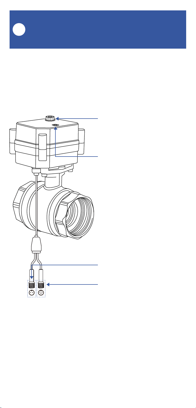
Get to Know Your Motorized
Valve
P
Manual Control Knob
Lift, then turn either clockwise to
shut the valve or
counterclockwise to open the
valve
Valve Position Indicator
Window indicates the current
position of the valve. “O”
indicates open, “S” indicates shut
Valve Control Cable
Valve Status Cable
(Specific models: your valve may
not have this cable)
The valve included in this kit is a 12V DC
non-smart motorized valve. Use only this valve
or YoLink-approved valve control products, such
as the Bulldog Valve Robot. Do not use with
non-YoLink valve products.

29
Install the Motorized Valve
Q
Preparing for installation:
Determine the installed location of your new
motorized valve. Please consider these factors
when choosing the location for the motorized
valve:
This location must be within reach of the
cables of the Valve Controller 2 (see Install
the Valve Controller 2 section, on page 12.
Ensure that there is physical room for the
valve, that other pipes, a wall or other
objects will prevent installing it at the
desired location.
The manual control knob and Open/Shut
indicator window should be visible and
accessible.
Please note, the valve can be installed in
any orientation; sideways, inverted, etc.
Local plumbing or building codes may
require a non-electronic means of water
shut-off. If this is the case, or if in doubt on
the requirements, install the motorized valve
in line (before or after) the existing shut-off
valve (ball valve, etc.)
30
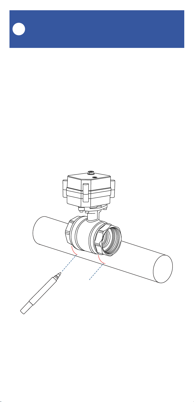
1. Shut-off the water serving the pipe where the
valve is to be installed. Drain the water from the
pipe, by turning on a faucet, or by other method
as required.
2. Depending on the adapter fitting used,
measure the length of pipe that must be cut, and
mark the cut lines on the pipe, as shown below.
Install the Motorized Valve,
Continued
Q
31
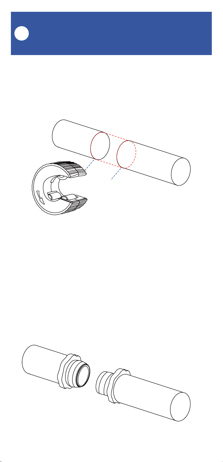
Install the Motorized Valve,
Continued
Q
3. Cut the water pipe through the mark using a
pipe cutting tool, then remove the cut section of
pipe, as shown below.
4. Sand both ends of cut pipe, removing any
burrs or rough edges. Use care handling the cut
edges, which may be sharp! Wipe off the cut
section of pipe with a clean cloth.
5. Install your adapter fittings in the pipe ends,
per the manufacturer instructions.
32
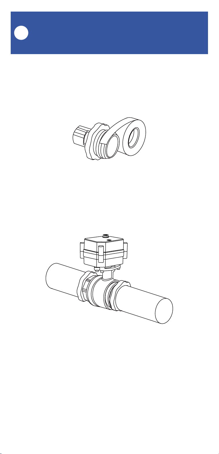
Install the Motorized Valve,
Continued
Q
6. Wrap each adapter’s threaded end with thread
seal tape, per the tape manufacturer’s instruc-
tions, as shown below.
7. Install the Motorized Valve on the adapter
fittings, ensuring a secure connection at each
fitting, as shown below.
8. At the water valve or point of disconnection,
turn the water on again.
9. Verify there are no leaks and no visible water
on the motorized valve.

33
Final Connections
R
1. Connect the valve controller’s valve control
cable (2-pin) to the control cable of the
motorized valve. Ensure the arrow of the cable
connector aligns with the arrow of the other
cable connector. Twist the collar of the
connector tight.
2. YS5003S, only: Connect the valve controller’s
valve status cable (3-pin) to the valve status
cable of the motorized valve, if applicable.
Ensure the arrow of the cable connector aligns
with the arrow of the other cable connector.
Twist the collar of the connector tight.
3. If using the 12VDC power input, via the
included plug-in power adapter or via your own
12VDC power supply, prior to plugging-in the
power supply/adapter or energizing the power
supply circuit, connect the valve controller’s
12VDC input cable to the power adapter or
12VDC power supply cable. Plug in the power
supply/adapter or energize the 12VDC power
supply circuit at this time. If you are electing to
power the valve controller only from the 12VDC
power input (not recommended), you can
remove the batteries at this time.

34
Manual Operation
S
It is recommended to always use the app or the
valve controller’s SET button to operate your
motorized valve.
Lift the knob on the top of the motorized valve
and turn it by hand, until it can not be turned.
Check the valve position indicator.
If you are not using the valve status feature or if
your valve controller does not have the valve
status feature, to avoid the app from indicating
the wrong valve status, if you manually closed
the valve, for example, manually open it again.
Do not open it via the app, after manually closing
it and vice versa, otherwise the app will incor-
rectly indicate the valve is closed.

35
Testing
T
1. Test the Valve Controller 2 and motorized
valve by pressing the SET button on the
controller. Listen for a smooth even sound from
the motorized valve. Once closed, ensure that no
water is flowing through the valve (the water
flowing through the valve may make an audible
sound). Check that no water flows from an open
faucet served by this valve.
2. Test the operation of the Valve Controller 2
from the app. From the Rooms or Favorite
screen, locate your Valve Controller 2, tap the
image, then tap Close to turn off the water, and
tap Open to turn it on.

36
Troubleshooting
U
Problem:
The valve controller is offline
Possible Solutions:
Ensure the Valve Controller 2 is on. Repeat
the Power Up section steps, if needed
Replace the batteries
Problem:
The valve controller does not respond to the SET
button being pressed and/or the Motorized Valve
Robot is unresponsive
Possible Solutions:
Ensure the Valve Controller 2 is on. Repeat
the Power Up section steps, if needed
Double check the cable connectors for
correct and tight connections
Replace the batteries

37
Troubleshooting, Continued
U
Problem:
The valve is indicated as closed in the app, but it
is actually open (or vice versa)
Possible Solution:
Non-valve-status controllers only:
disconnect the valve controller from the
Motorized Valve. Manually operate the
Motorized Valve, moving it to the open
position if it was closed, and to the closed
position if it was open. Reconnect the valve
controller to the Motorized Valve. Test the
Motorized Valve and valve controller from
the app, and verify it is now correctly
indicated as open or closed

38
Control-D2D Device-to-Device
Pairing
V
YoLink Control-D2D is our unique
device-to-device control technology. Using
Control-D2D, compatible YoLink devices can
control or be controlled by other YoLink devices,
without a hub or internet connection. One device
can control another device, directly.
A device that controls or sends out commands is
called the controller. A device that is controlled
or receives the commands is called the
responder. An example of a controller are a
Water Leak Sensor, while examples of a
responder are a Siren Alarm or a Valve Controller
2.
Use of YoLink Control-D2D is optional.
One device can be Control-D2D-paired to up to
128 other devices.
Pairing is separate from the app and any
automation, scenes or alarm strategies you may
have configured in the app. Use care to not
create automations that conflict with
Control-D2D-pairing and vice-versa.
During pairing, the controlled device must be in
the state (open, on, unlocked, etc.) that it should
transfer to when signalled by the controller.
39
Pairing
1. To configure a Water Leak Sensor 1 as a con-
troller, press and hold the leak sensor’s SET
button for 5-10 seconds, until the LED quickly
blinks green, then release the button.
2. To configure the Valve Controller 2 as a
responder, first ensure that the valve or Bulldog
is in the closed position. Press and hold the
controller’s SET button for 5-10 seconds until
the LED quickly blinks green, then release the
button.
Upon pairing, the LED will stop blinking. This
may happen after only blinking two or three
times.
SET Button
(5-10 seconds)
SET Button
(5-10 seconds)
Control-D2D Device-to-Device
Pairing, Continued
V

40
Testing
1. Ensure the valve is in the normal (open)
position.
2. Test the water leak sensor (if needed, refer to
the sensor user guide for testing instructions).
3. Verify that the valve closes immediately when
the leak sensor is activated.
Unpairing
1. At the Water Leak Sensor, press and hold the
SET button for 10-15 seconds, until the LED
quickly blinks green then red, then release the
button.
2. At the Valve Controller 2, press and hold the
SET button for 10-15 seconds, until the LED
quickly blinks green then red, then release the
button.
Upon unpairing, either the Water Leak Sensor
LED or the Valve Controller 2 LED will stop
blinking and turn off.
At this time, you can test the leak sensor to
confirm it no longer activates the valve
controller. If you also have any automations or
alarm strategies that may also control the valve
controller, disable them before testing.
Control-D2D Device-to-Device
Pairing, Continued
V

41
Please visit our website’s Support page for the
YoLink app guide and for product-specific app
settings and instructions:
www.yosmart.com/support-and-service
Using the App & 3rd-Party
Services
W
Factory reset will erase device settings and
restore it to factory default settings. Doing a
factory reset will not remove the device from
your account and it will not harm the device, or
lose any data or require you to redo your auto-
mations, etc.
Instructions:
Hold the SET button down for 20-30 seconds,
until the LED blinks red and green alternately.
Then, release the button. (Holding the button
down longer than 30 seconds will abort the
factory reset operation)
Factory reset will be complete when the LED
stops blinking.
Only deleting a device from the app will remove
it from your account. Factory reset will not
delete the device from the app.
Factory Reset
X

42
Your YoLink products are constantly being
improved, with new features added. It is
periodically necessary to make changes to your
device's firmware. For optimal performance of
your system, and to give you access to all
available features for your devices, these
firmware updates should be installed when they
become available.
In the Detail screen of each device, at the
bottom, you will see the Firmware section, as
shown in the image below. A firmware update is
available for your device if it says "#### ready
now"
Tap in this area to start the update.
The device will update automatically, indicating
progress by percentage-complete. You may use
your device during the update, as the update is
performed "in the background". The LED will
slowly blink green during the update, and the
update may continue for several minutes beyond
the LED turning off.
Firmware Update
Y
43
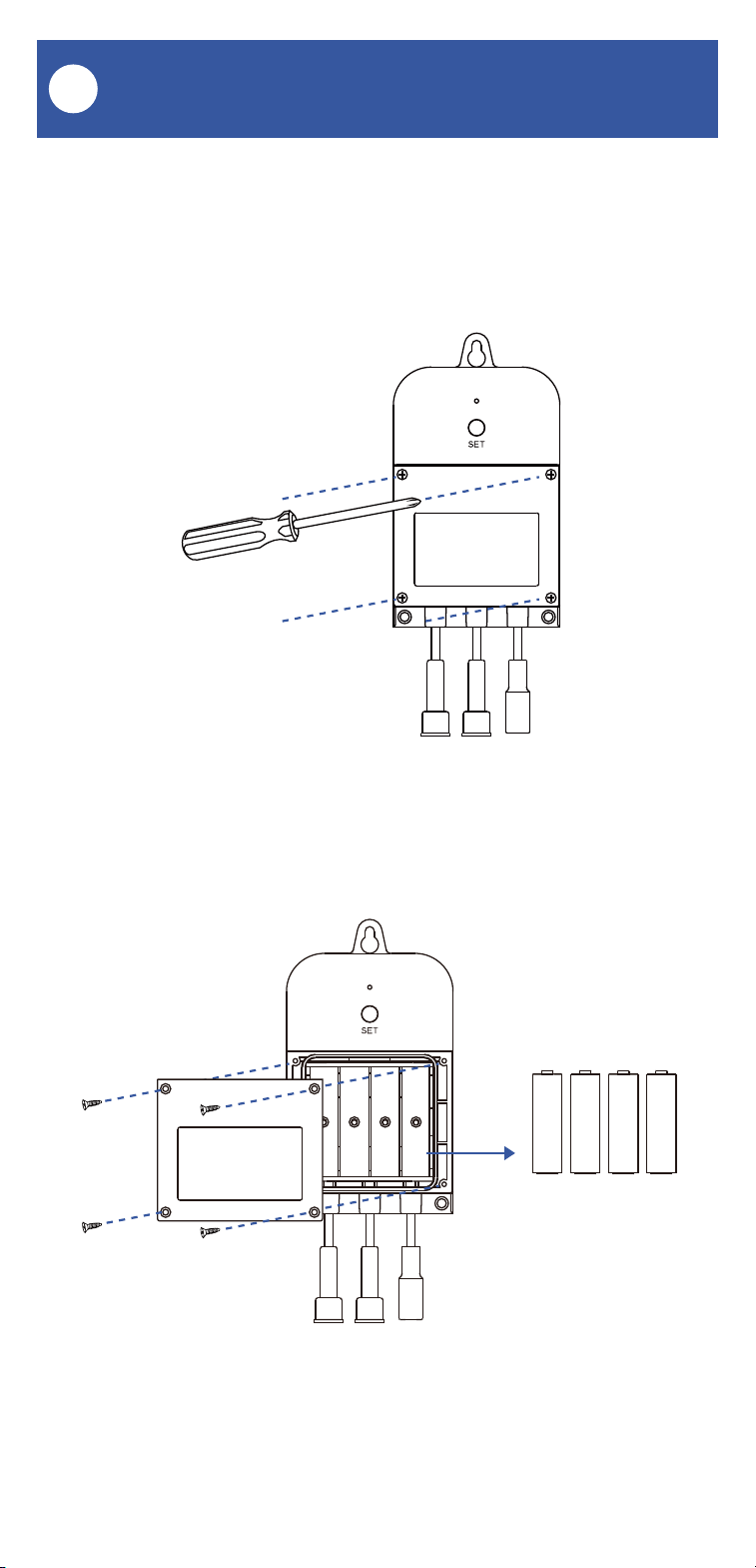
Battery Replacement
Z
1. Using a Phillips screwdriver, loosen the four
battery cover screws, and remove the battery
compartment cover.
2. Remove all four batteries.
44
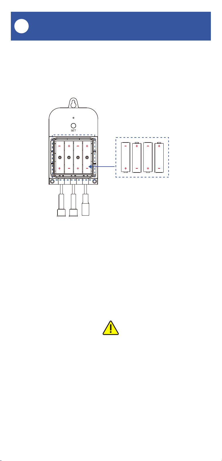
The Valve Controller 2 can be powered by alka-
line or lithium-ion batteries. Do not use
rechargeable or other type batteries.
Battery Replacement, Continued
Z
3. Observing the correct battery position and
polarity, replace them with new AA batteries
4. Replace the battery compartment cover and
tighten the screws.
5. In the app, verify the Valve Controller 2 is
online and the batteries are indicated as good.

45
Please install, operate and maintain the
Valve Controller 2 (and Motorized Valve or
Bulldog Valve Robot) only as outlined in this
manual. Improper installation or use may
damage the unit and/or void the warranty.
Do not install or use the device outside of
the temperature and humidity range listed in
the environmental specifications.
If used outdoors, for the maximum life of the
device, provide overhead cover or a
protective enclosure. This can protect it
from the damaging effects of intense direct
sunlight and/or rain over a period of years.
Do not immerse or allow the devices to be
immersed or submerged in water.
Avoid placing the devices in extremely dirty
or dusty environments.
If the device does get dirty, please clean it
by wiping it down with a clean dry cloth. Do
not use strong chemicals or detergents,
which may damage or discolor the exterior
and/or damage the electronics, voiding the
warranty.
Do not install the device where it may be
subjected to vandalism, abuse, physical
impacts or strong vibrations. Physical
damage is not covered by the warranty.
Warnings
AA

46
Power the controller only with new AA
alkaline or lithium-ion batteries. Do not use
rechargeable batteries, do not use other
type batteries (e.g. zinc blend). Do not mix
old and new batteries.
If storing the controller for extended periods,
remove the batteries.
Please contact Customer Support before
attempting to repair, disassemble or modify
the device, any of which can permanently
damage the device and void the warranty.
Warnings, Continued
AA

47
Warranty
1 Year Limited Mechanical Device Warranty
2 Year Limited Electrical Device Warranty
YoSmart warrants to the original user of this
product that it will be free from defects in
materials and manufacturing workmanship,
under normal use, for 1 year from the date of
purchase for motorized valves and the Bulldog
Valve Robot and for 2 years from the date of
purchase for the Valve Controller 2.
The warranty does not cover abuse or misused
products, nor does this warranty apply to
products that have been improperly installed,
were modified, or put to a use other than
designed. This warranty does not cover products
subjected to acts of God (such as floods,
lightning strike or electrical surge, or
earthquakes, etc.).
This warranty is limited to repair or replacement
of the product only at YoSmart’s sole discretion.
YoSmart will NOT be liable for any costs
associated with removing or reinstalling the
product. YoSmart will NOT be liable for direct or
indirect or consequential damages to persons or
property resulting from the use of this product.
The warranty only covers the cost of
replacement products or parts. It does not cover
shipping and handling charges or fees.
To implement this warranty, please refer to the
Contact Us section of this guide.
AB

48
This equipment has been tested and found to
comply with the limits for a Class B digital device,
pursuant to part 15 of the FCC Rules. These
limits are designed to provide reasonable
protection against harmful interference in a
residential installation. This equipment
generates, uses and can radiate radio frequency
energy and, if not installed and used in
accordance with the instructions, may cause
harmful interference to radio communications.
However, there is no guarantee that interference
will not occur in a particular installation. If this
equipment does cause harmful interference to
radio or television reception, which can be
determined by turning the equipment off and on,
the user is encouraged to try to correct the
interference by one or more of the following
measures: Reorient or relocate the receiving
antenna, connect the equipment into an outlet on
a circuit different from that to which the receiver
is connected, increase the separation between
the equipment and receiver, consult the dealer or
an experienced radio/TV technician for help.
This device complies with part 15 of the FCC
Rules. Operation is subject to the following two
conditions:
1) This device may not cause harmful
interference
2) This device must accept any interference
received, including interference that may cause
undesired operation. Any changes or
modifications not expressly approved by the
party responsible for compliance could void the
user's authority to operate the equipment.
FCC Statement
AC

49
FCC Statement, Continued
PRODUCT NAME:
Valve Controller 2
PARTY:
YOSMART, INC.
TELEPHONE:
831-292-4831
MODEL NUMBER:
YS-5003-UC
ADDRESS:
15375 BARRANCA PKWY SUITE J-107, IRVINE,
CA 92618 USA
EMAIL:
SERVICE@YOSMART.COM
AC

50
IC Caution
-English:
This device complies with Industry Canada
licence-exempt RSS standard(s). Operation is
subject to the following two conditions:
(1) This device may not cause interference, and
(2) This device must accept any interference,
including interference that may cause undesired
operation of the device.
To maintain compliance with RSS-102 RF
Exposure guidelines, This equipment should be
installed and operated with minimum 20cm
distance between the radiator and your body:
Use only the supplied antenna.
-French:
Le présentappareilestconf orme aux CNR d'
Industrie Canada applicables aux appareils radio
exempts de licence. L'exploitationestautorisée
aux deux conditions suivantes:
(1) l'appareil ne doit pas produire de brouillage,
et
(2) I' utilisateur de l'appareildoit accepter tout
brouillageradioélectriquesubi, mêmesi le
brouillageest susceptible d'encompromettre le
fonctionnement.
Pour être conforme aux lignes directrices
d'exposition RF RSS-102, cet équipement doit
être installé et exploité à une distance minimale
de 20cm entre le radiateur et votre corps:
n'utilisez que l'antenne fournie.
AD

51
We are here for you, if you ever need any assis-
tance installing, setting up or using a YoLink app
or product!
Need help? For fastest service, please email us
24/7 at [email protected]
Or call us at 831-292-4831 (US phone support
hours: Monday - Friday, 9AM to 5PM Pacific)
You can also find additional support and ways to
contact us at:
www.yosmart.com/support-and-service
Or scan the QR code:
Finally, if you have any feedback or suggestions
for us, please email us at
Thank you for trusting YoLink!
Eric Vanzo
Customer Experience Manager
Support Home Page
15375 Barranca Parkway Ste. J-107 | Irvine, California 92618
© 2023 YOSMART, INC IRVINE, CALIFORNIA
Contact Us
AE