
AWRT10RF Wireless
Radiant Thermostat
Installation & Operation Instruction Manual
As of February 21, 2019

Table of Contents
1.0 Introduction
1.1 - Box Contents.....................................................................................................4
1.2 - Using this Manual ................................................................................................4
1.3 - Product Safety Information .......................................................................................5
1.4 - SALUS Smart Home Application ..................................................................................5
1.5 - SALUS Wireless System Constraints ...............................................................................5
2.0 AWRT10RF Thermostat Installation Flow Charts
2.0 - Installation with Internet Connection .............................................................................6
2.1 - Installation without Internet Connection..........................................................................7
3.0 AWRT10RF Thermostat Installation
Mounting & Optional External Temperature Sensor Wiring .............................................................8
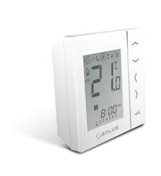
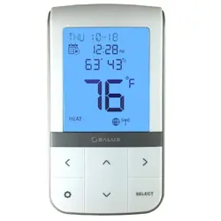
4.0 AWRT10RF Thermostat Display & Keypad
4.1 -Home Screen and Key Functions ................................................................................ 10
4.2 - Display Screen Boot Sequence.................................................................................. 10
5.0 Pairing with Wireless Devices using SG888ZB Gateway
5.1 - Relay Controller (AKL01PRF/AKL04PRF/AK06PRF/AKL08RF) ...................................................... 11
5.2 - Radiator Valves (ARV10RFM/AVA10M30RF) ...................................................................... 15
5.3 - Receiver (AX10RF – RX1)........................................................................................ 19
5.4 - Receiver (AX10RF – RX1)........................................................................................ 22
6.0 SALUS Smart Home Application
6.1 - Parameter Settings ............................................................................................. 26
6.2 - Schedule Setup ................................................................................................ 26
6.3 - Remote Operation ............................................................................................. 27
7.0 Pairing with Wireless Devices using AC10RF Coordinator
7.1 - Relay Controller (AKL01PRF/AKL04PRF/AK06PRF/AKL08RF) ...................................................... 29
7.2 - Radiator Valves (ARV10RFM/AVA10M30RF) ...................................................................... 32
7.3 - Receiver (AX10RF – RX1)........................................................................................ 35
7.4 - Receiver (AX10RF – RX2)........................................................................................ 37
8.0 AWRT10RF Thermostat Settings & Parameters
8.1 - Parameter & Settings Adjustment using Display & Keypad ....................................................... 39
8.2 - Thermostat Settings Table ...................................................................................... 40
8.3 - Thermostat Parameter Table .................................................................................... 41
8.4 - Schedule Setup using Display & Keypad......................................................................... 43

Table of Contents
9.0 AWRT10RF Thermostat Operation – Display/Keypad
9.1 - Setting the HVAC Mode using the Display & Keypad ............................................................. 45
9.2 - Setting the Temperature Setpoint in Non-programmable Mode.................................................. 45
9.3 - Overriding Scheduled Temperature using the Display & Keypad ................................................. 46
10.0 Troubleshooting
10.1 - Error Messages................................................................................................ 47
10.2 - Reading Multiple Error Messages .............................................................................. 48
10.3 - External Sensor Resistance Graph.............................................................................. 48
11.0 Technical Specifications
Thermostat Dimensions............................................................................................. 49
Specications....................................................................................................... 49
12.0 Installer Notes
4
Introduction
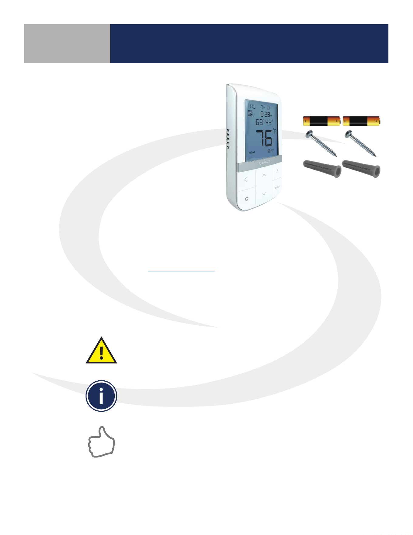
1.1 Box Contents
• AWRT10RF Wireless Radiant Thermostat
with backplate
• (2) AA Alkaline Batteries (installed)
• (2) Mounting Screws
• (2) Plastic Wall Anchors
• Quick Start Guide
1.2 Using this Manual
For the latest instructions go to: www.salusinc.com
Special Attention Boxes
This manual uses special attention icons to alert the reader of important safety concerns,
information important to reliable operation of the controls or helpful installation/setup information
Safety:
Indicates a condition which may cause severe personal
injury, death or major property damage
Important Information:
Indicates information which requires special attention
for correct operation of the control
Your Benet:
Indicates helpful installation or setup information
Section 1.0
5
Introduction
1.3 Product Safety Information
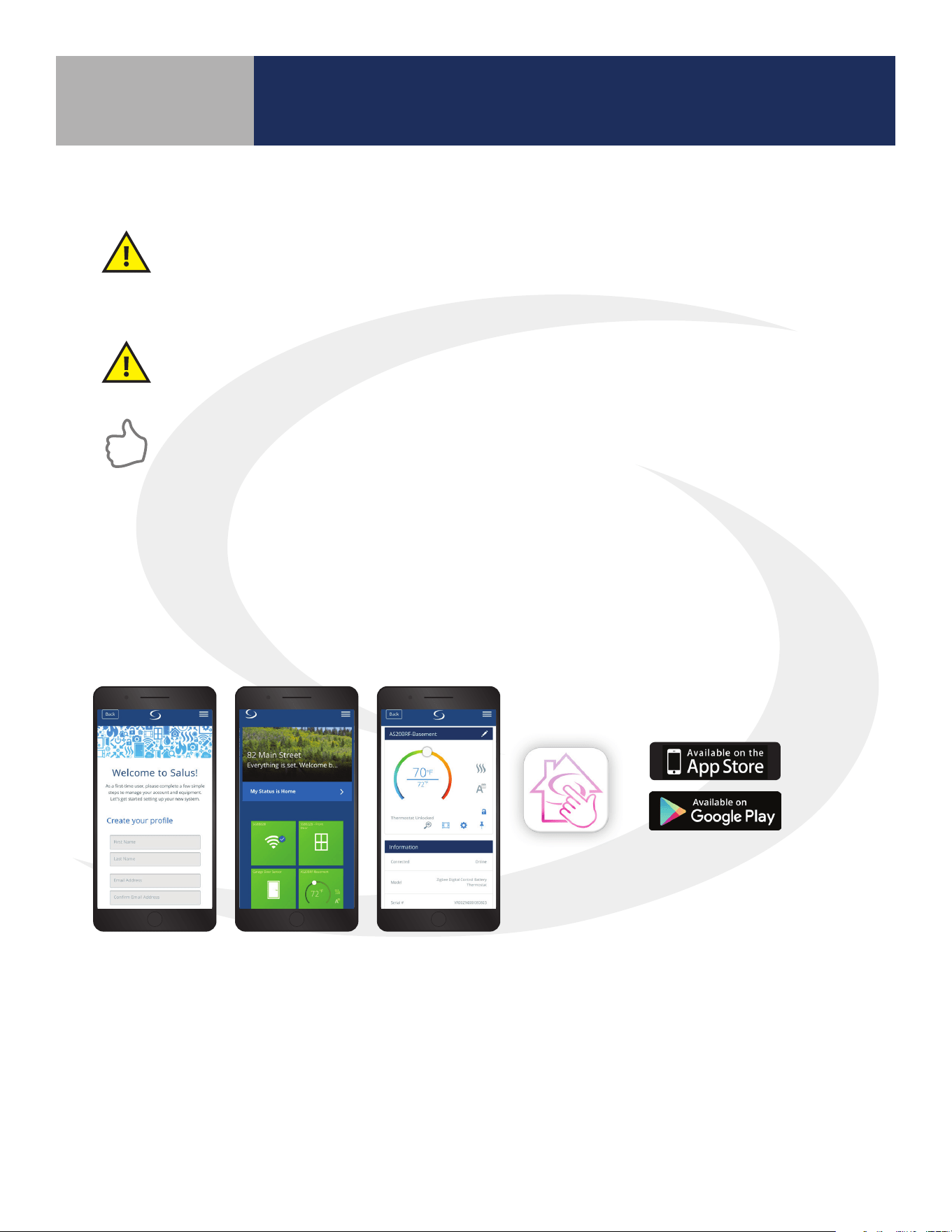
1.4 SALUS Smart Home Application
Use SALUS Smart Home to:
• Quickly view and monitor the status of your home and smart devices
• Set schedules and preferences for your connected thermostats, smart plugs and more
• Receive important real-time alerts and notications of any changes that occur with your system
Codes & Regulations: Installation and setup of this product must be performed in strict
compliance with country, state/province and local regulating agencies and codes that deal with
Class B digital devices. In the absence of local requirements, the FCC rules, listed below, are to be
followed.
Intended Use: The SALUS AWRT10RF Wireless Thermostat is intended for interior room
temperature control in conjunction with hydronic heating systems only. Other uses are not
recommended or supported.
Installer or Contractor: Record any parameter changes in Section 12, Installer Notes.
As a first time user please complete a few
simple steps to manage your account and
equipment. Let’s get started setting up your
new system.
Welcome to HeatLink
®
!
Create your profile
First Name
Last Name
Email Address
Confirm Email Address
Back
HeatLink
As a first time user please complete a few
simple steps to manage your account and
equipment. Let’s get started setting up your
new system.
Welcome to HeatLink
®
!
Create your profile
First Name
Last Name
Email Address
Confirm Email Address
Back
HeatLink
As a first time user please complete a few
simple steps to manage your account and
equipment. Let’s get started setting up your
new system.
Welcome to HeatLink
®
!
Create your profile
First Name
Last Name
Email Address
Confirm Email Address
Back
HeatLink
1.5 SALUS Wireless System Constraints
• A maximum of 9 AKL Series Relay Controllers can be connected to each SALUS Wireless System
• A maximum of 6 ARV10RFM or AVA10M30RF can be connected to each AWRT10RF Thermostat
• Only 1 AX10RF (RX1) and 1 AX10RF (RX2) can be connected to each SALUS Wireless System
Download the SALUS Smart Home application on your IOS or Android device for remote access to your home
comfort system. For security purposes you will be prompted to set up a user prole including username & password.
Apple, the Apple logo, iPhone, and iPod touch are trademarks of
Apple Inc, registered in the U.S. and other countries. App Store is a
service mark of Apple Inc, registered in the U.S. and other countries
Google Play and the Google Play logo are trademarks of Google LLC.
Section 1.0
6
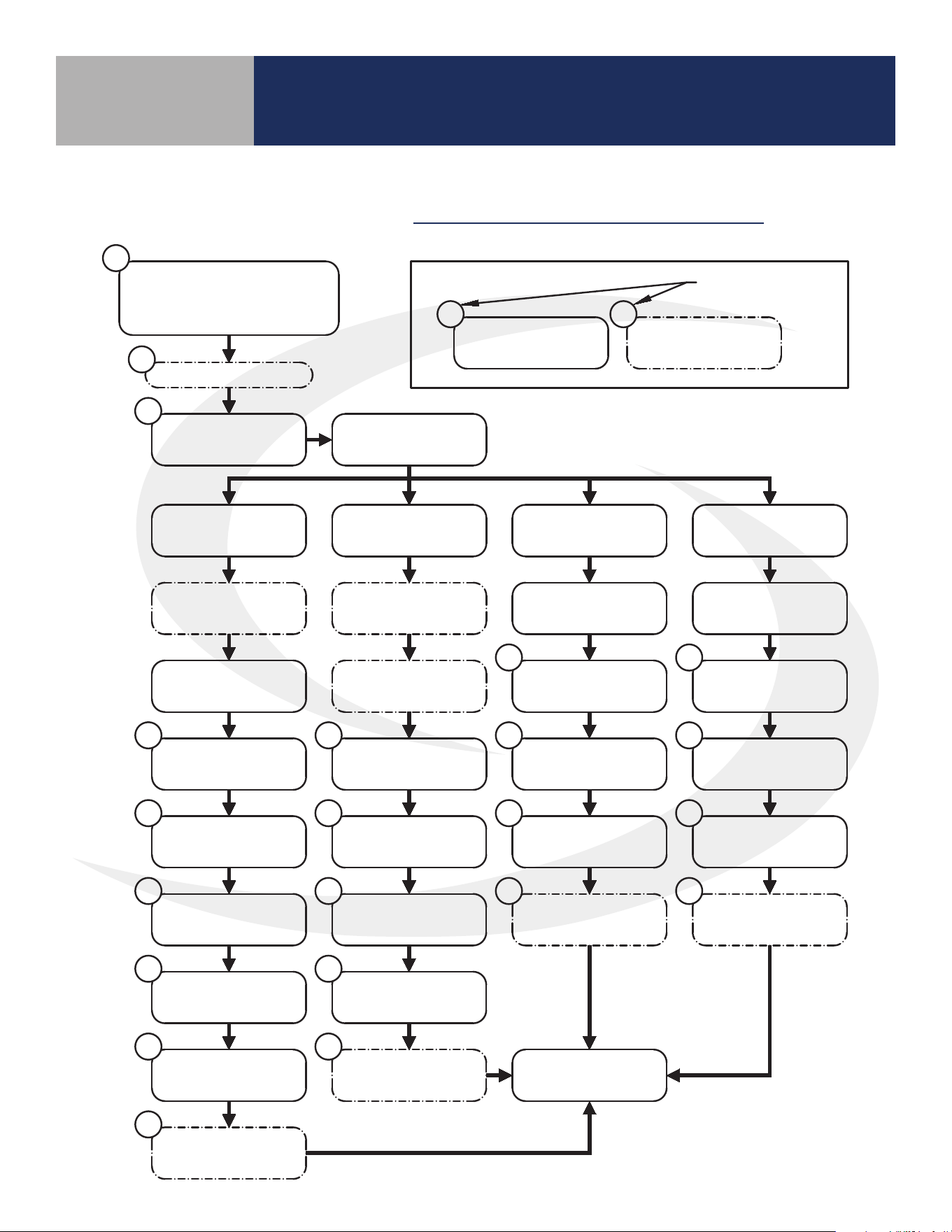
2.1 Installation with Internet Connection
Section 2.0
AWRT10RF Thermostat Installation Flow Charts
Download SALUS Smart Home
Application, Setup Profile &
Associate SG888ZB Gateway
Mount AWRT10RF
Backplate
Decide on
Device to Control
Install AKL Relay
Controller
Install ARV/AVA
Valve Actuator(s)
Install AX10RF
Receiver (RX1)
Install AX10RF
Receiver (RX2)
Install Receiver
(RX1)
Install Receiver
(RX1)
Apply Power to
AX10
Apply Power to
AKL/AX10
Apply Power to
AX10
Apply Power to
AX10
AWRT: Remove
Battery Tab
AWRT: Remove
Battery Tab
AWRT: Remove
Battery Tab
AWRT - Select
PAIR? RLAY CTL
ARV/AVA - Place
in Pairing Mode
App: Scan & Add
AKL/AWRT/AX
AKL: Identify Relay
Controller ID#
AWRT: Set Controller
& Zone #
AWRT: Set
Parameters
AWRT: Select
PAIR? RDTR_VLV
AWRT: Set
Parameters
AWRT - Select
PAIR? RCV1
App: Scan & Add
AX/AWRT
AWRT: Set
Parameters
AWRT - Select
PAIR? RCV2
App: Scan & Add
AX/AWRT
AWRT: Set
Parameters
Attach External Sensor
5
8
9
9
11
12
13
14
41
41
41 41
9 9
16
19
22
16
20
22
Home Screen
App: Scan & Add
ARV/AVA/AWRT/AX
15
AWRT: Remove
Battery Tab
9
Required Step
Optional Step
##
##
Reference Page
Number
KEY:
INSTALLATION with INTERNET CONNECTION
7
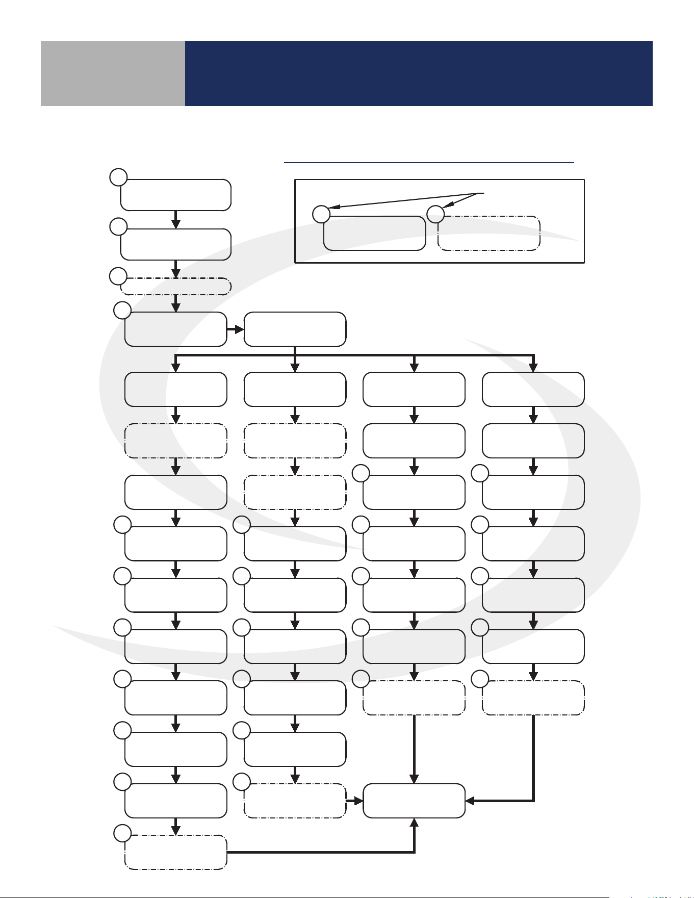
2.2 Installation without Internet Connection
Section 2.0
AWRT10RF Thermostat Installation Flow Charts
Install AC10RF
Coordinator
Mount AWRT10RF
Backplate
Decide on
Device to Control
Install AKL Relay
Controller
Install ARV/AVA
Valve Actuator(s)
Install AX10RF
Receiver (RX1)
Install AX10RF
Receiver (RX2)
Install Receiver
(RX1)
Install Receiver
(RX1)
Apply Power to
AX10
Apply Power to
AKL/AX10
Apply Power to
AX10
Apply Power to
AX10
AWRT: Remove
Battery Tab
AC10RF: Press
Pairing Button
AWRT - Select
PAIR? RDTR_VLV
AWRT: Select
PAIR? RLAY CTL
AWRT: Set Controller
& Zone #
AWRT: Set
Parameters
AWRT: Set
Parameters
AWRT - Select
PAIR? RCV1
AWRT: Set
Parameters
AWRT - Select
PAIR? RCV2
AWRT: Set
Parameters
Attach External Sensor
29
8
9
9
29
30
31
41
41
41 41
9
9 9
33
35 37
Home Screen
AC10RF: Press
Pairing Button
32
ARV/AVA: Press
Pairing Button
32
AKL: Identify Relay
Controller ID#
30
AC10RF: Press
Pairing Button
31
AC10RF: Press
Pairing Button
34
AC10RF: Press
Pairing Button
35
AC10RF: Press
Pairing Button
37
AC10RF: Press
Pairing Button
36
AC10RF: Press
Pairing Button
38
Update AC10RF
Firmware
29
AWRT: Remove
Battery Tab
AWRT: Remove
Battery Tab
AWRT: Remove
Battery Tab
INSTALLATION without INTERNET CONNECTION
Required Step
Optional Step
##
##
Reference Page
Number
KEY:
8
AWRT10RF Thermostat Installation
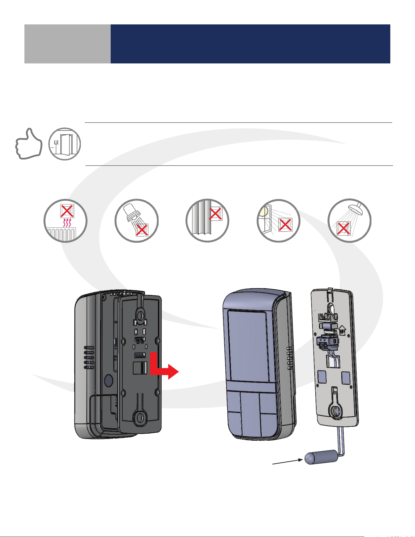
Avoid mounting the AWRT10RF Thermostat on an exterior wall.
Step 1. Ensure that all required parts were included in the package.
DO NOT Mount the AS20 Thermostat near any heat source, behind curtains, in direct sunlight,
in areas of high humidity or area where water is present.
SALUS components must be set up for wireless communication with the SG888ZB Gateway or with
the AC10RF Coordinator. This process, called “pairing”, should be performed with all devices installed
in their intended location. If the intended operating location is unsuitable for the pairing process for
convenience or other factors, the device may be located in a convenient location during pairing.
Step 2. Remove the AWRT10RF Thermostat
from the backplate by lifting the tab in the
top center and sliding the base downward.
Step 3. Connect an external 10 kΩ NTC sensor
(AFTS30M sold separately), if desired, to the
sensor terminals on the backplate.
Section 3.0
Mounting and Optional Temperature Sensor Wiring
Temperature
Sensor
9
AWRT10RF Thermostat Installation
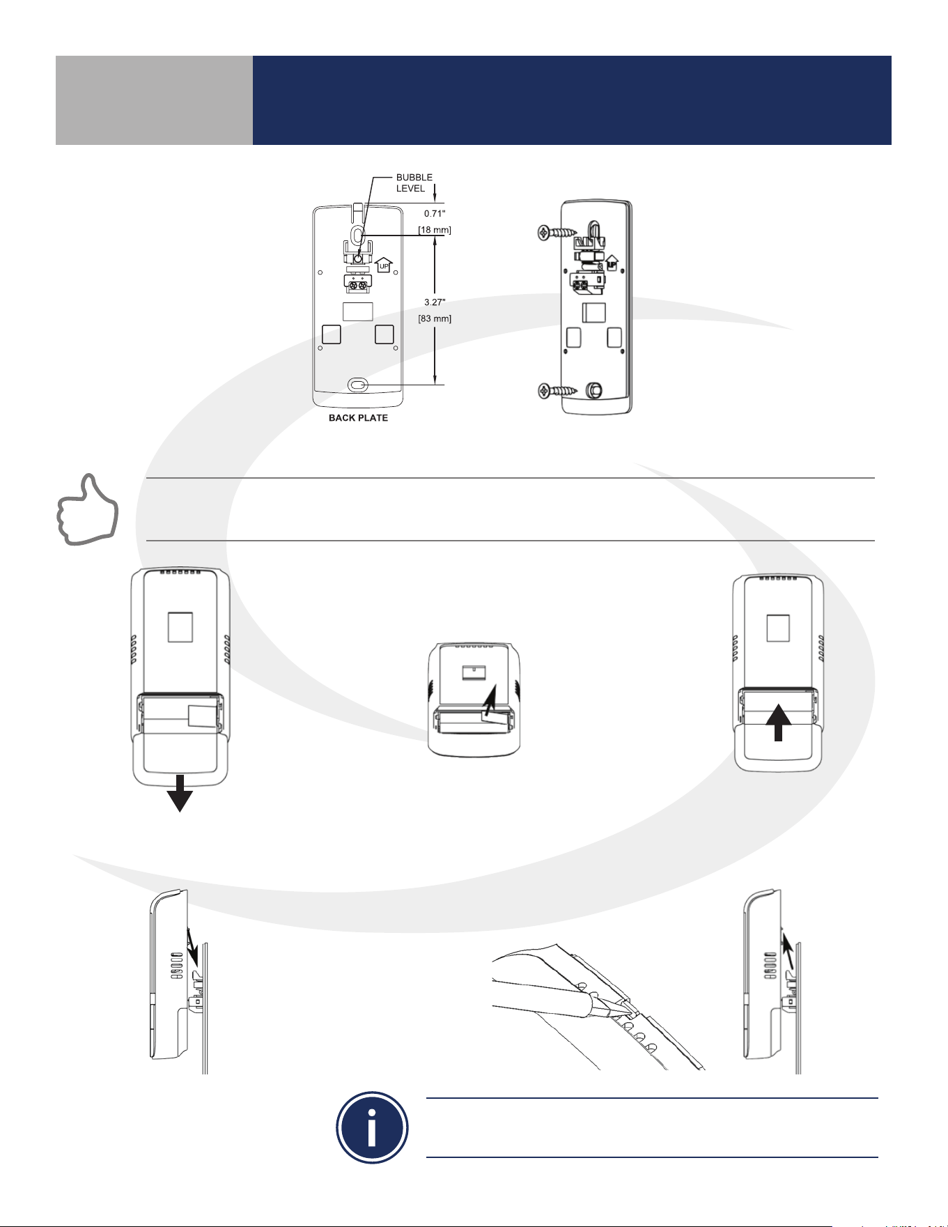
Step 4. Secure the backplate to the wall using the provide screws and wall anchors
FOR BEST RESULTS, ensure that the AWRT10RF Thermostat backplate is level, using the integral bubble level,
when mounting it. NOTE THE ORIENTATION ARROW molded into the backplate indicating correct orientation.
Step 5. Open the
battery compartment
Step 6. Remove the battery tab to
power the AWRT10RF Thermostat
Step 7. Close the
battery compartment
Step 8. Attach the AWRT
Thermostat by positioning
it against the backplate
and sliding downward.
The AWRT Thermostat can be removed by gently pushing the latch
at the top of the thermostat and sliding the thermostat upward.
Section 3.0
10
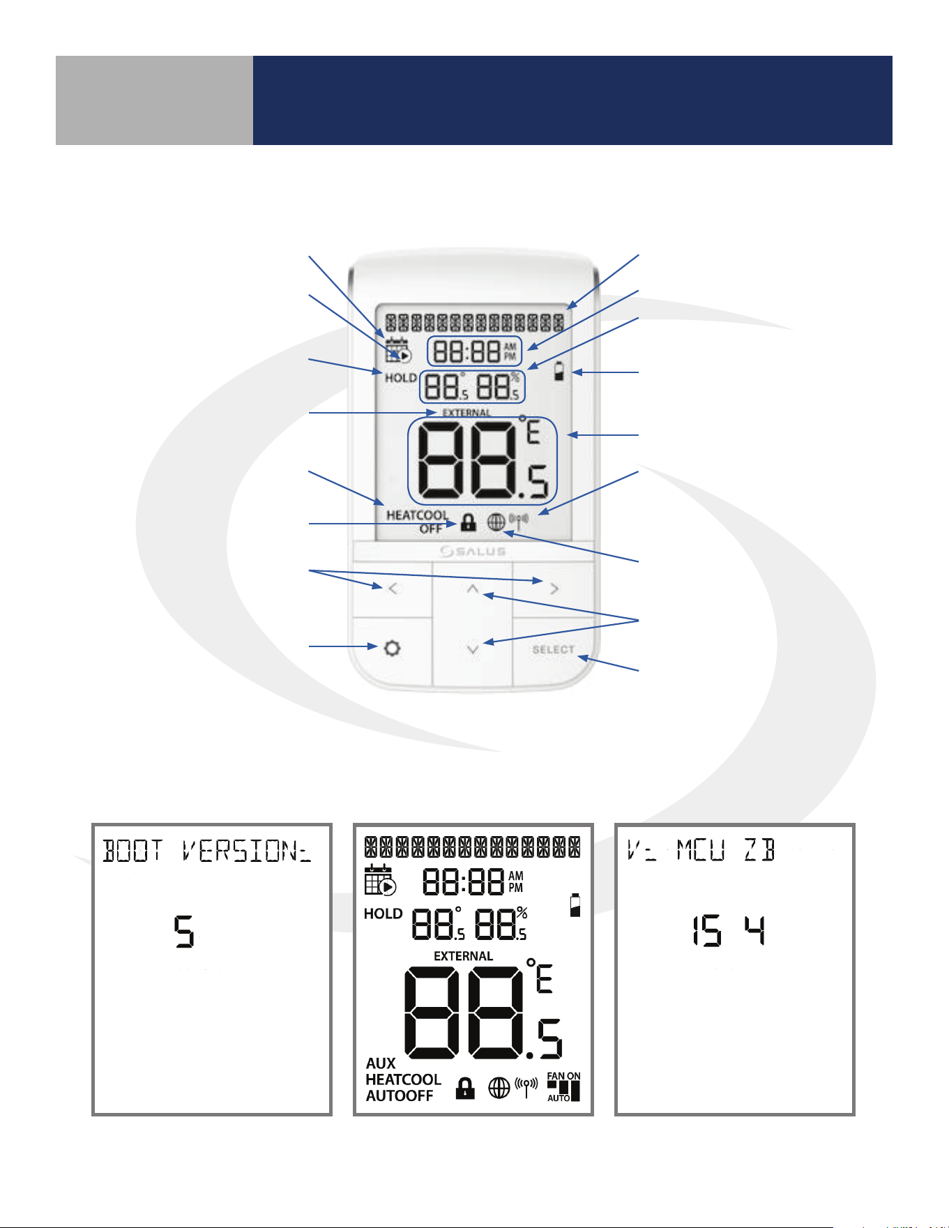
AWRT10RF Thermostat Display & Keypad
4.2 Display Screen Boot Sequence
Alphanumeric Text Display
Time Display
Multifunction Display:
Setpoint and Relative Humidity
Low Battery Indicator
Room Temperature Display
Network Status Indicator
SALUS Smart Home Service
Connection Status Indicator
Increment/Decrement Value
Conrm Selection
Displays boot loader version
number for 3 seconds
Displays all available LCD
segments for 3 seconds
Displays MCU rmware and
Zigbee code for 3 seconds
Schedule Present
Schedule Running
Hold Indicator
(Temporary or Permanent)
External Temperature
Sensor Present
Mode Display
Key Lock Indicator
Mode/Menu Option Scroll
Settings
Section 4.0
4.1 Home Screen and Key Functions
11
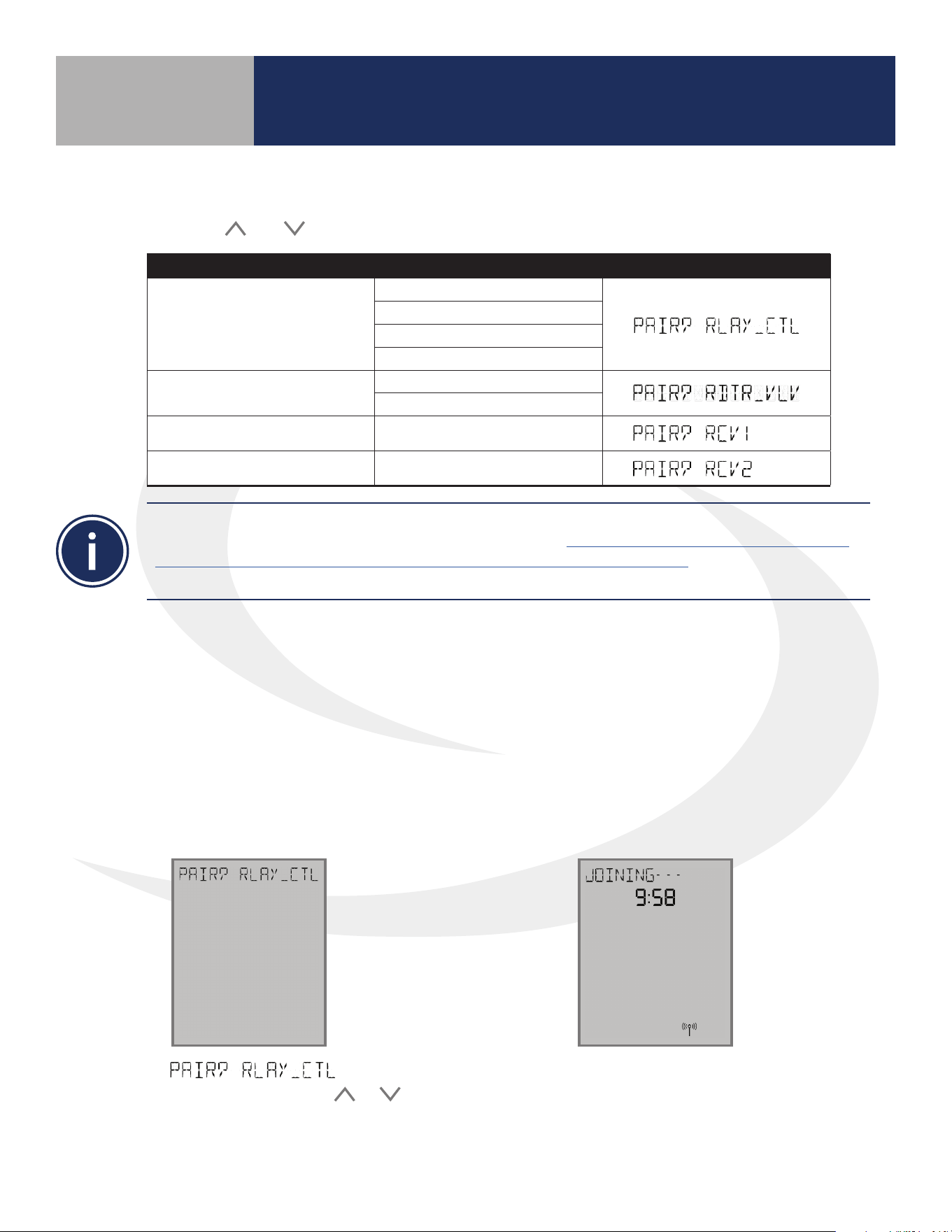
Pairing With Wireless Devices Using
SG888ZB Gateway (w/ Internet Connection)
DEVICE MODEL(S) DISPLAY
Relay Controller
AKL01PRF
AKL04PRF
AKL06PRF
AKL08RF
Radiator Valve
ARV10RFM-3
AVA10M30RF
Receiver (RX1) AX10RF (RX1)
Receiver (RX2) AX10RF (RX2)
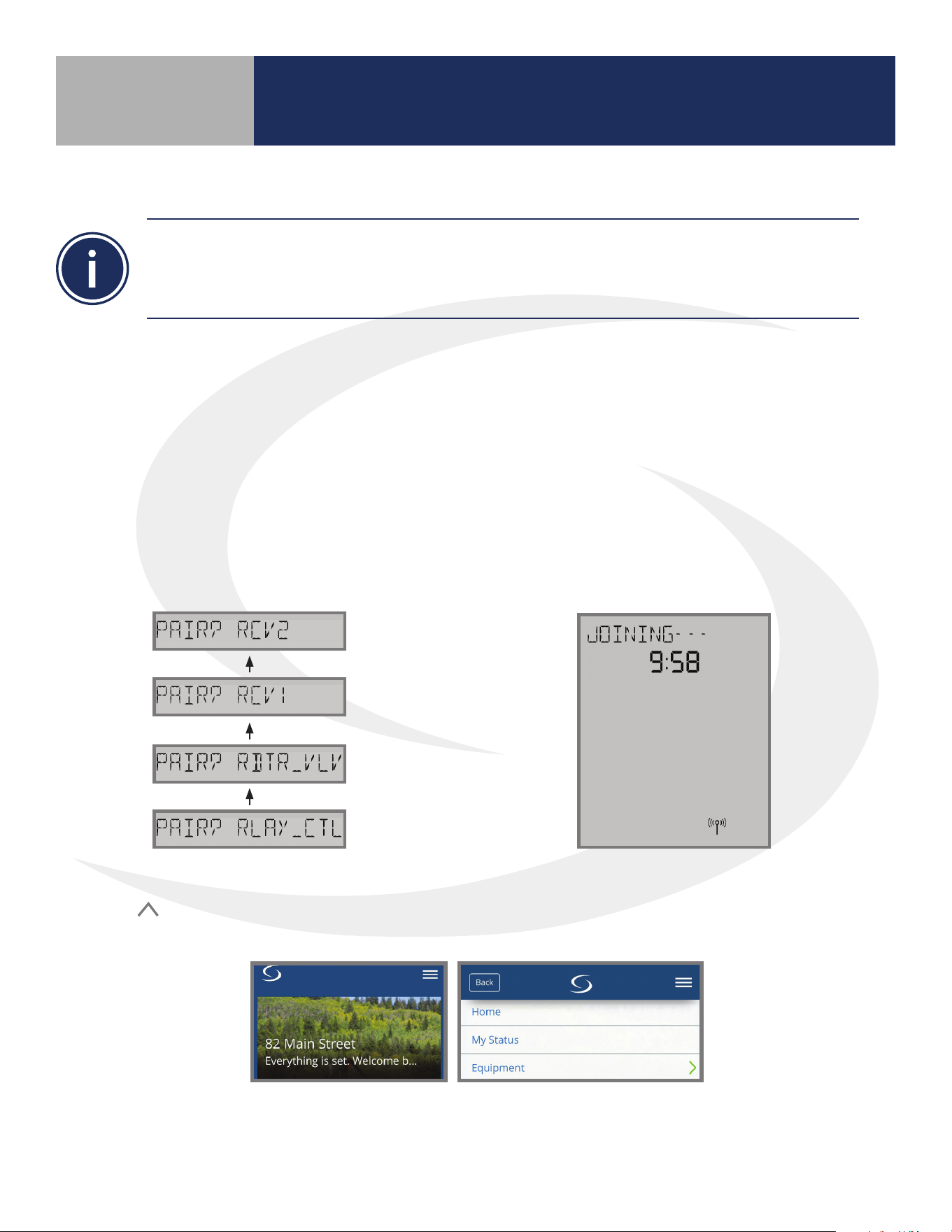
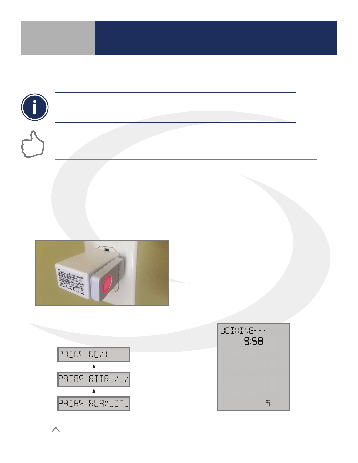
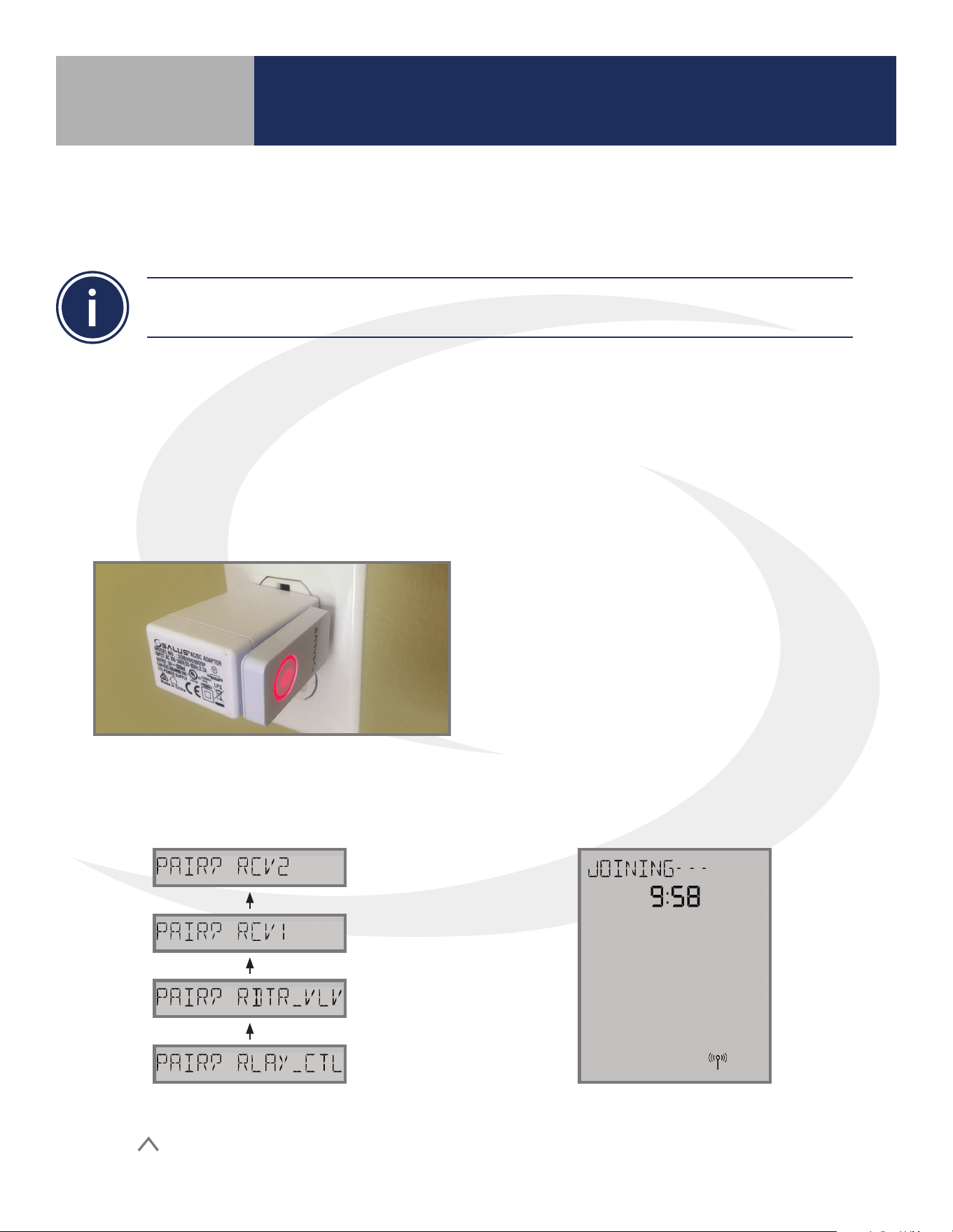
After the boot up sequence on the initial power up, the AWRT10RF immediately enters the pairing
process. Use the
and keys to select between the following devices:
5.1 – Pairing with AKL01/04/06PRF
and AKL08RF Relay Controllers
To connect the AWRT Wireless Radiant Thermostat and other components using an SG888ZB Gateway,
the gateway must be installed and activated. Please see the SALUS SG888ZB Installation Instructions
(https://www.salusinc.com/wp-content/uploads/2017/10/BZG_IUG-ENv4.pdf) for information about
setting up the gateway.
Before pairing, the AKL Series Relay Controller and optional AX10RF Receiver (if desired) must be
installed and powered in accordance with installation instructions included with these devices.
• The LED ring on the SG888ZB Gateway should be solid blue
• The Network Status LED on the AKL Relay Controller should be ashing
• If an AX10RF Receiver is used, the LED backlight on the Auto/Manual switch of this device
should be ashing red and the switch should be in the Auto position
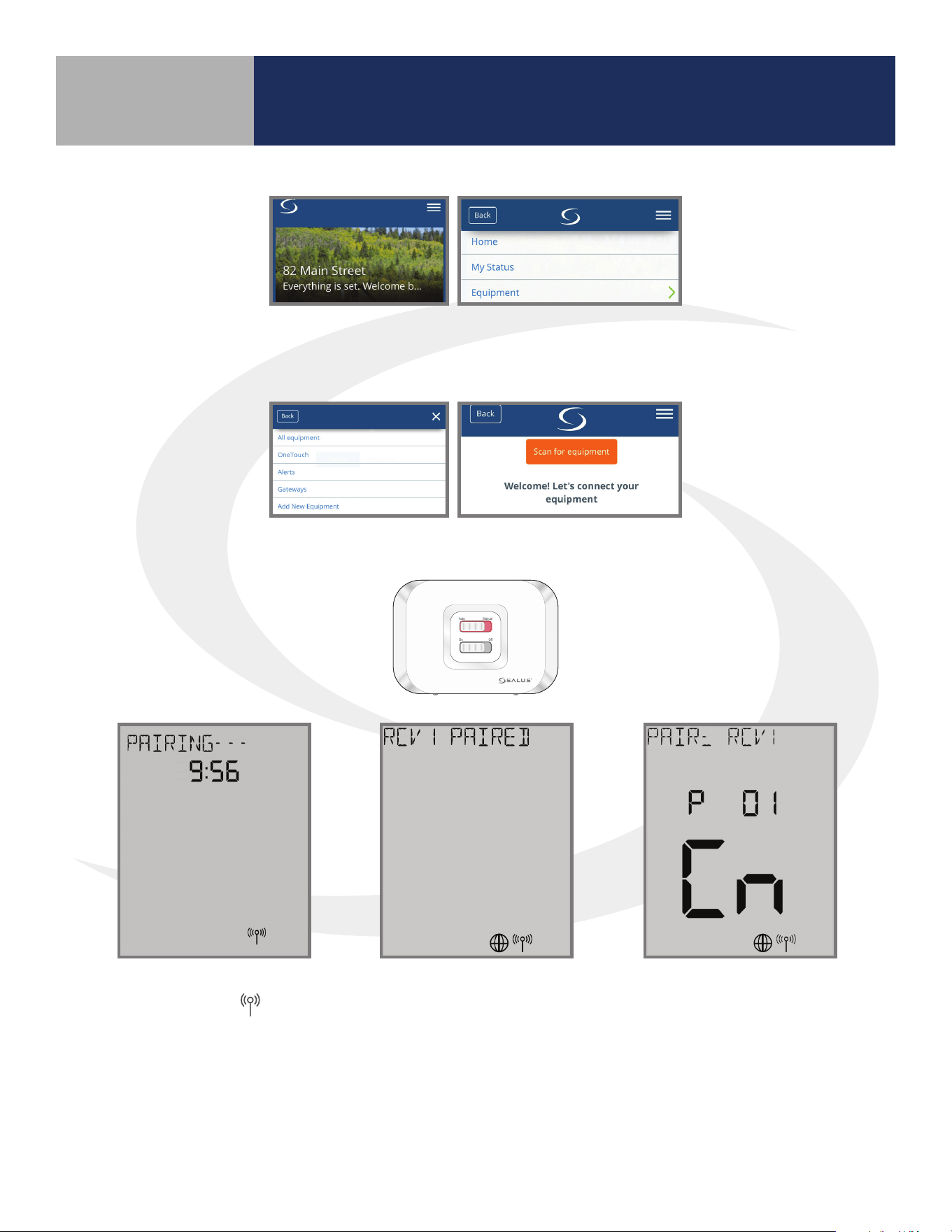
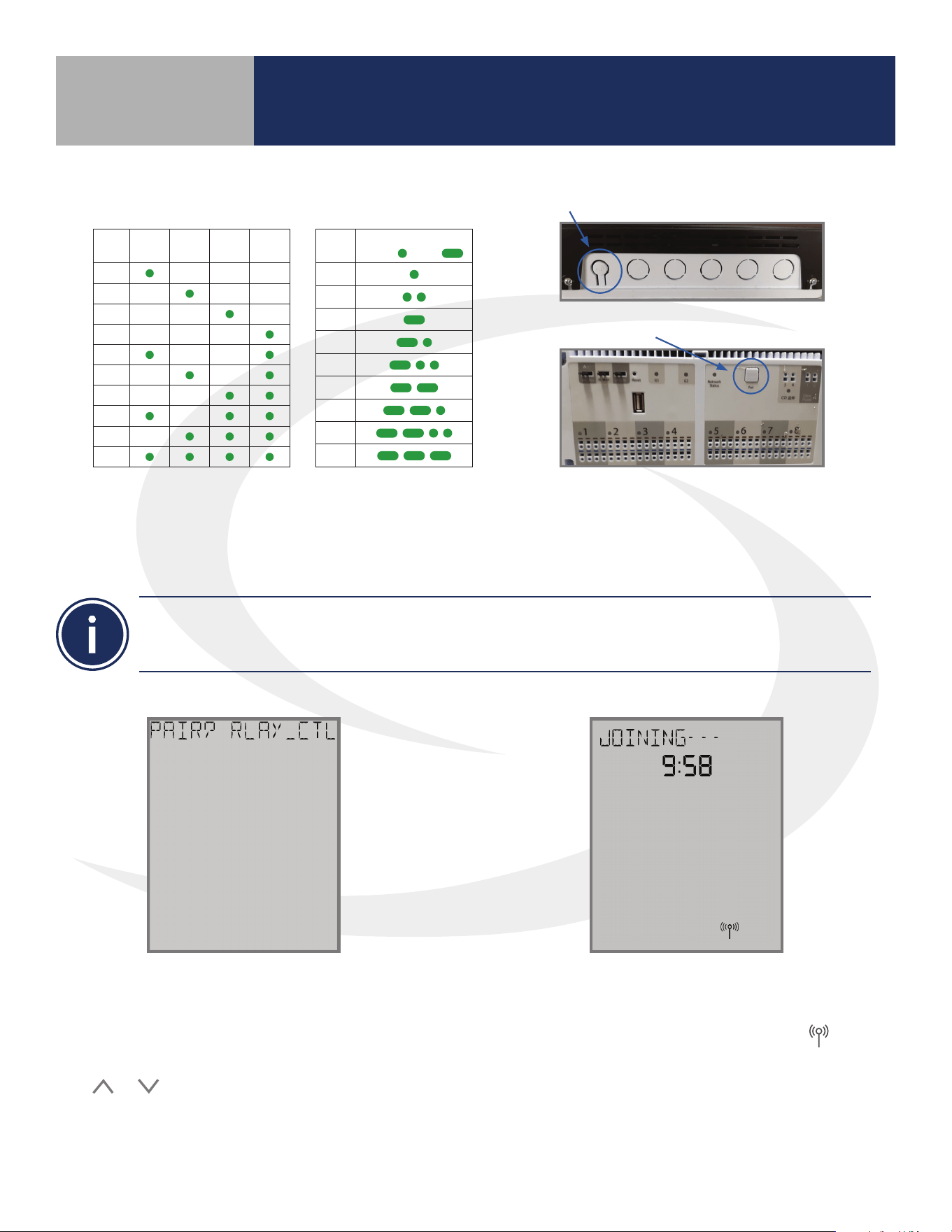
Step 1. If is not
displayed and ashing, use the
or
keys to display it. Press the SELECT key
on the AWRT10RF Thermostat.
The display will show JOINING- - - with a 10 minute
countdown timer to show how much time is
available to complete the next steps. The icon will
ash at the bottom of the screen indicating that the
thermostat is searching for a network to join.
Section 5.0
12
Pairing with Wireless Devices Using
SG888ZB Gateway (w/ Internet Connection)
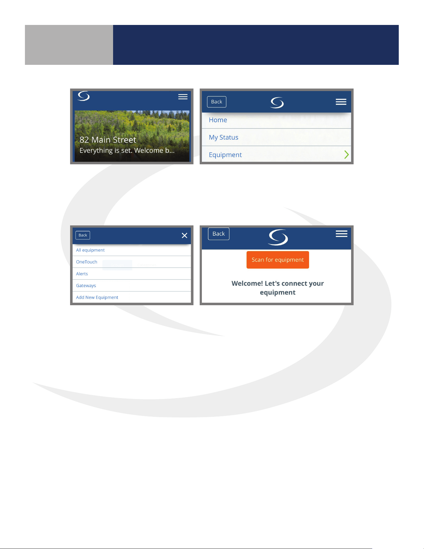
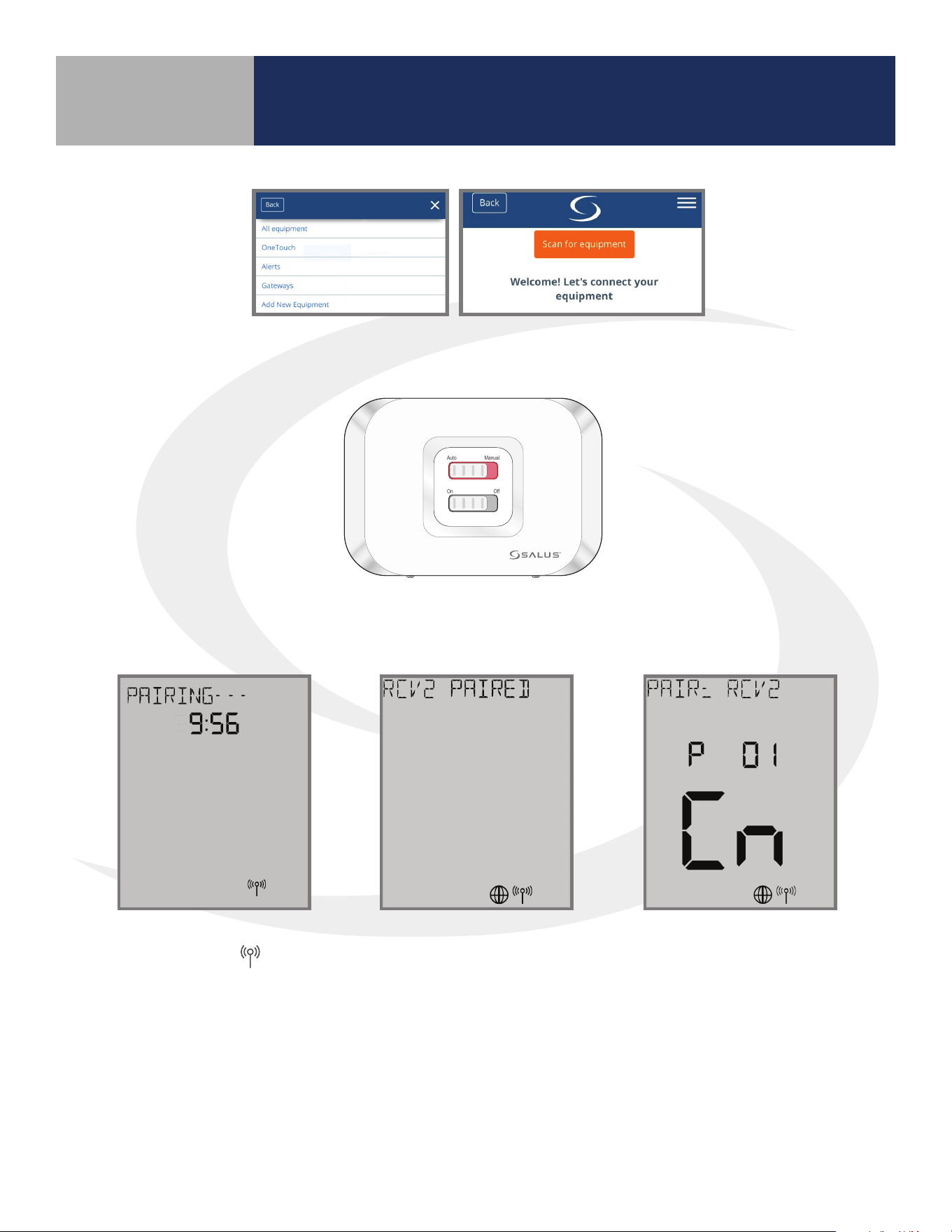
Step 2. Open the SALUS Smart Home application, select the drop down menu from the upper
right of the screen and select:
Equipment
Add New Equipment Scan for Equipment
Step 3. Click the “Scan for equipment” button. The SG888ZB Gateway’s LED will ash red as it
searches for devices.
When the components are joined to the network
• The Network Status Indicator on the AWRT10RF Thermostat will turn steady on,
• T he Network Status LED on the AKL Series Relay Controller will turn steady on, and
• I f present, the red LED backlight on the Auto/Manual switch of the AX10RF Receiver
will turn steady on
Section 5.0
13
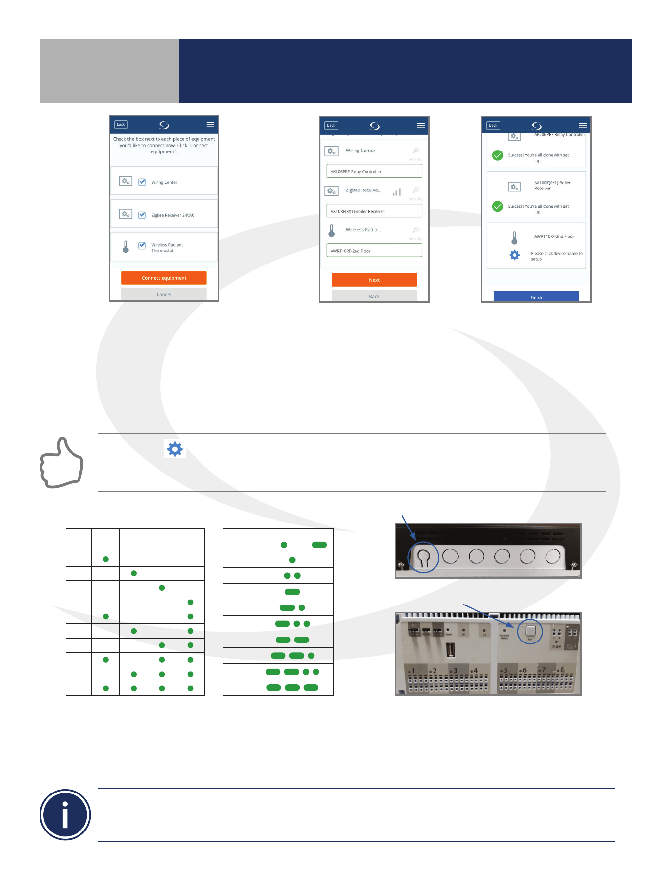
Step 7. Once the AKL Relay Controller is connected (network status LED is no longer ashing), briey
press the pairing button (shown above) on the relay controller. Zone LEDs on the AKL Relay Controller
will illuminate indicating the ID number of the AKL device. This number will be used to set up
thermostats to address the correct relay controller.
ID #
Zone
1
Zone
2
Zone
3
Zone
4
1
2
3
4
5
6
7
8
9
0
AKL Relay
Controller ID
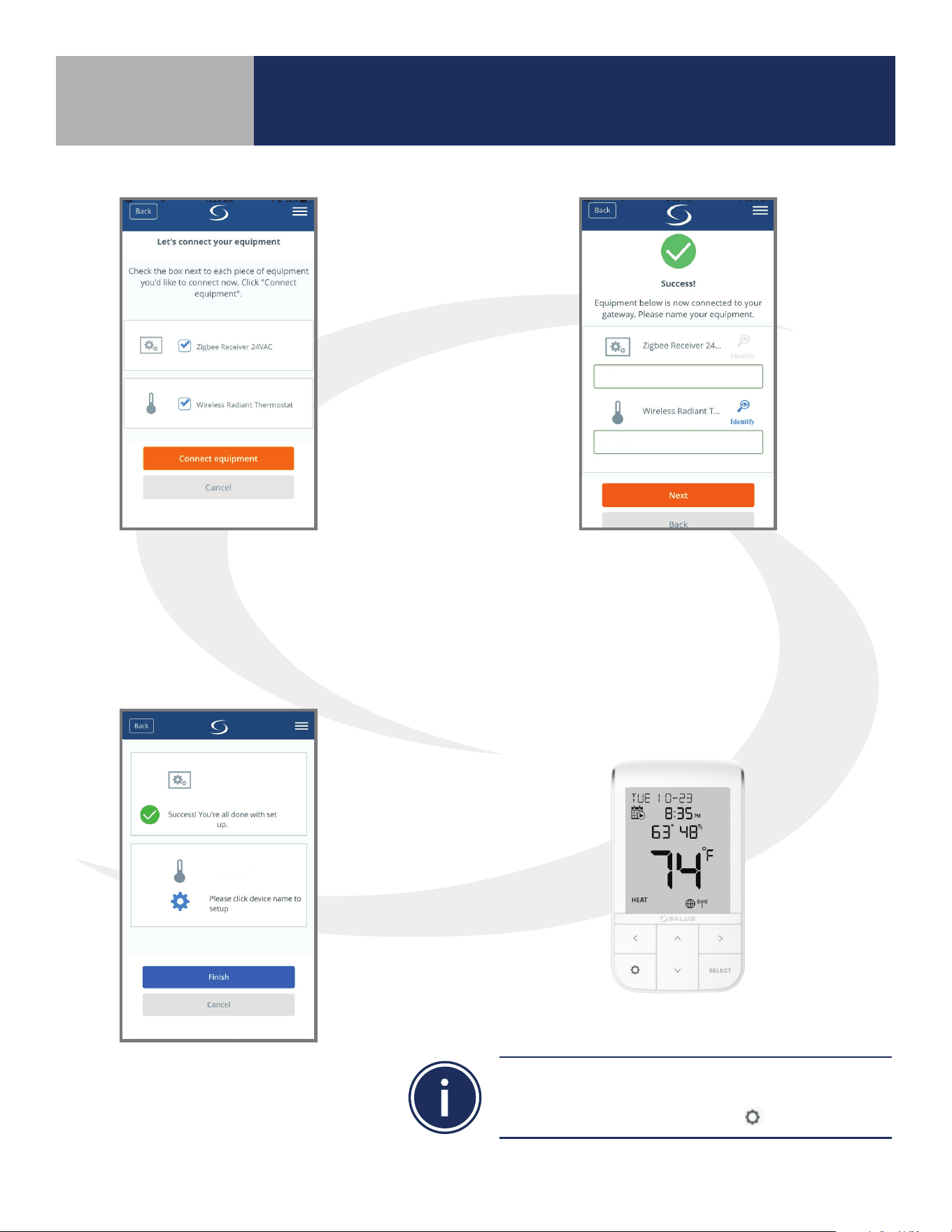
Step 4. Select the check boxes for both
the Wiring Center (Relay Controller)
and the Zigbee Receiver on the SALUS
Smart Home application. Then press
the “Connect equipment” button. The
SG888ZB Gateway LED ring will return
to steady blue.
Step 5. Give each device a
descriptive name that allows
easy identication. If there
are multiple relay controllers,
identify each with respect to
its location and/or purpose.
Step 6. Press “Finish”
to save the device
information.
Pressing the icon on the AWRT10RF Thermostat prior to pressing Finish on the SALUS Smart Home
application starts the thermostat parameter setup. As covered in Section 8 of this manual, this can be
setup after completing the pairing process.
• When zone LEDs are illuminated in ID mode, the illuminated zone outputs will be activated.
• The AKL01PRF Relay Controller uses the pulse codes shown above to identify the ID number. A short
pulse = 1 and a long pulse = 3. Add the pulse values of all pulses for the ID of the relay controller.
AKL01 Relay Controller ID#
Zone LED Pulse Code
ID #
LED Pattern
Short = , Long =
1
2
3
4
5
6
7
8
9
AKL01/04/06PRF Relay Controller Pairing Button
AKL08RF Relay Controller Pairing Button
Pairing with Wireless Devices Using
SG888ZB Gateway (w/ Internet Connection)
Section 5.0
14
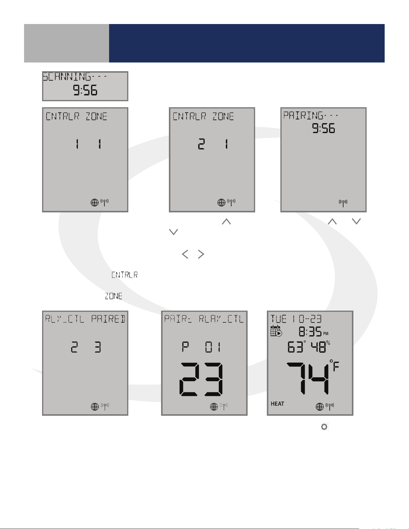
When the AWRT10RF Thermostat has
found all controllers in the network, it
will display the default relay controller
value (1) and the default zone value (1).
If there is more than 1 relay controller on
the network, the left value
will
ash. If there is only one relay controller,
the right-hand value for
will ash.
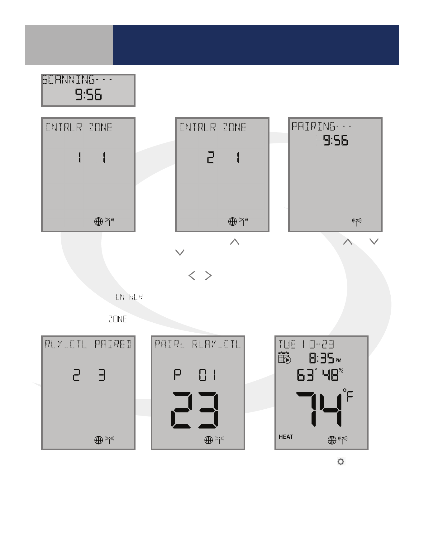
Step 8. Use the
and
keys to change the
CONTROLLER value, then
the
or key to switch to
the ZONE.
Step 10. Press the
key to exit
parameter setup and go to the Home
Screen. The display shows the current
date & time, target temperature,
relative humidity, network/internet
status and room temperature.
The AWRT10RF Thermostat
will enter parameter setup
mode, starting with parameter
P 01. The current device type
along with the Zigbee channel
number will be displayed.
Once the AWRT10RF Thermostat has joined the network, SCANNING-
- - is displayed with a 10-minute countdown timer showing the time
allowed to nd all the relay controllers on the network
Step 9. Use the and
keys to change the ZONE
value, then press SELECT.
The AWRT10RF Thermostat
will then display
PAIRING- - - as it associates
with the selected
controller and zone.
When paired, RLY_CTL
PAIRED will be displayed
briey along with the
CNTRLR value and
ZONE value.
Pairing with Wireless Devices Using
SG888ZB Gateway (w/ Internet Connection)
Section 5.0
15
Before beginning, it is important that the ARV/AVA Radiator Valve Actuator is installed and adapted
properly as detailed in the installation instructions. The following is a review of those instructions.
ARV/AVA Radiator Valve Actuator Installation Review
Step 1. Install the batteries and wait until the LED is
solid red before installing the actuator on the radiator
valve. Remember that the knurled nut on the actuator
should only be nger tight. Using pliers or other tools
can damage the device.
DO NOT BEGIN pairing with the ARV/AVA Radiator Valve Actuator unless the light is out and there is no
motor activity. Listen closely to the Valve Actuator to be sure it is not operating before proceeding.
Step 2. After attaching the actuator to the valve,
press any of the buttons to initialize the ARV10RFM
or AVA10M30RF Radiator Valve Actuator. This process
may take several minutes, and the valve may continue
to initialize after the light is no longer illuminated.
ARV/AVA Radiator Valve Actuator Pairing Procedure
Before pairing, the radiator valve actuators and optional AX10RF Receiver (if desired) must be
installed and powered in accordance with the installation instructions include with the devices.
• The LED ring on the SG888ZB Gateway should be solid blue
• The LED on the ARV/AVA Valve Actuator(s) should be o with NO MOTOR ACTIVITY,
• If an AX10RF Receiver is used, the LED backlight on the Auto/Manual switch of this device
should be ashing red with the switch in the Auto position.
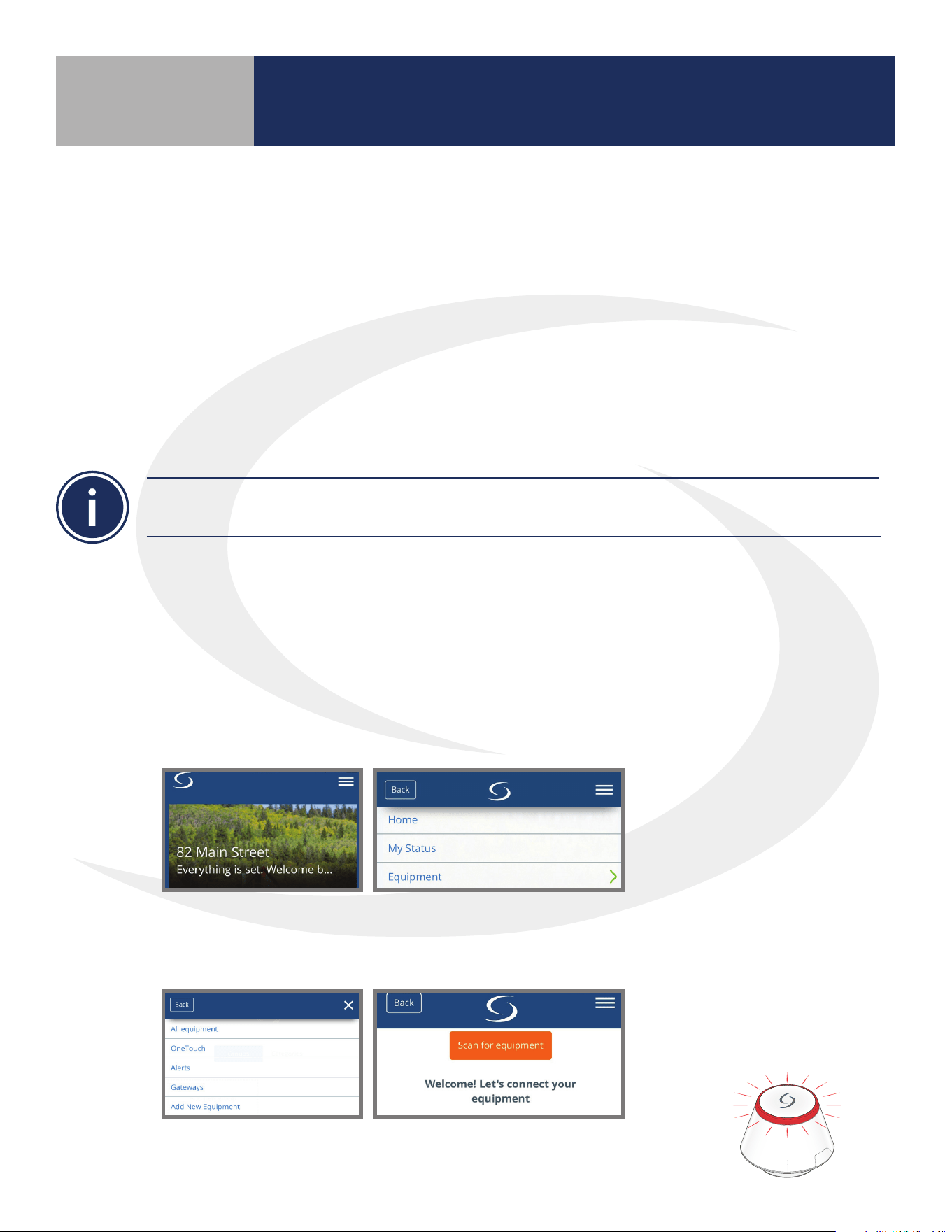
Step 1. Open the SALUS Smart Home mobile application and select the drop down menu from the
upper right side of the screen select:
Equipment
Add New Equipment Scan for Equipment
Step 2. Click the “Scan for equipment” button. The SG888ZB Basic Gateway’s LED
will ash red as it searches for devices.
Pairing with Wireless Devices Using
SG888ZB Gateway (w/ Internet Connection)
Section 5.0
5.2 – Pairing with ARV10RFM or AVA10M30RF Radiator Valve Actuators
16
10 seconds The LED indicator will ash red.
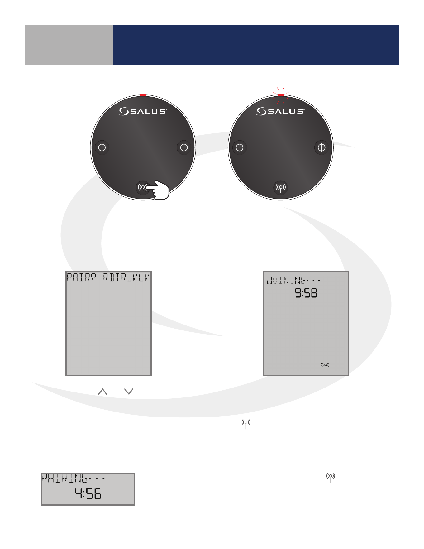
Step 3. Press and hold the pair button for 10 seconds to enter pairing mode on each actuator
to be connected.
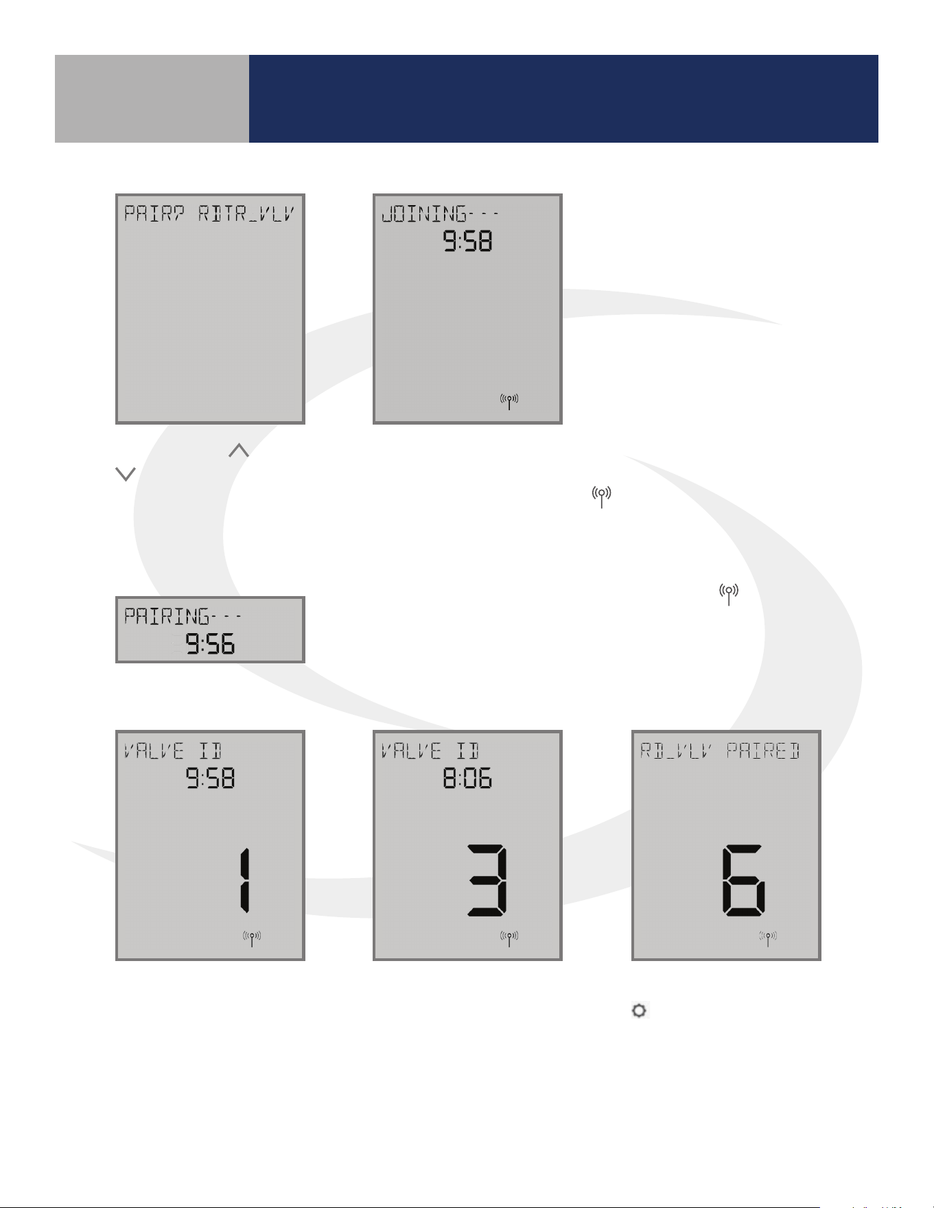
JOINING- - - is displayed with a 10 minute
countdown timer to show the remaining
time available to complete the next steps.
The
icon will ash at the bottom of the
screen indicating that the thermostat is
searching for a network to join.
Step 4. Use the and keys on the
AWRT10RF Thermostat to switch from
RLAY_CTL to RDTR_VLV. Press SELECT
to initiate pairing.
Once the AWRT10RF Thermostat joins a network, the icon will stop
ashing and the network channel will be briey displayed. After that,
PAIRING- - - is displayed with a countdown timer showing the time
allowed for the remaining pairing steps.
Pairing with Wireless Devices Using
SG888ZB Gateway (w/ Internet Connection)
Section 5.0
17
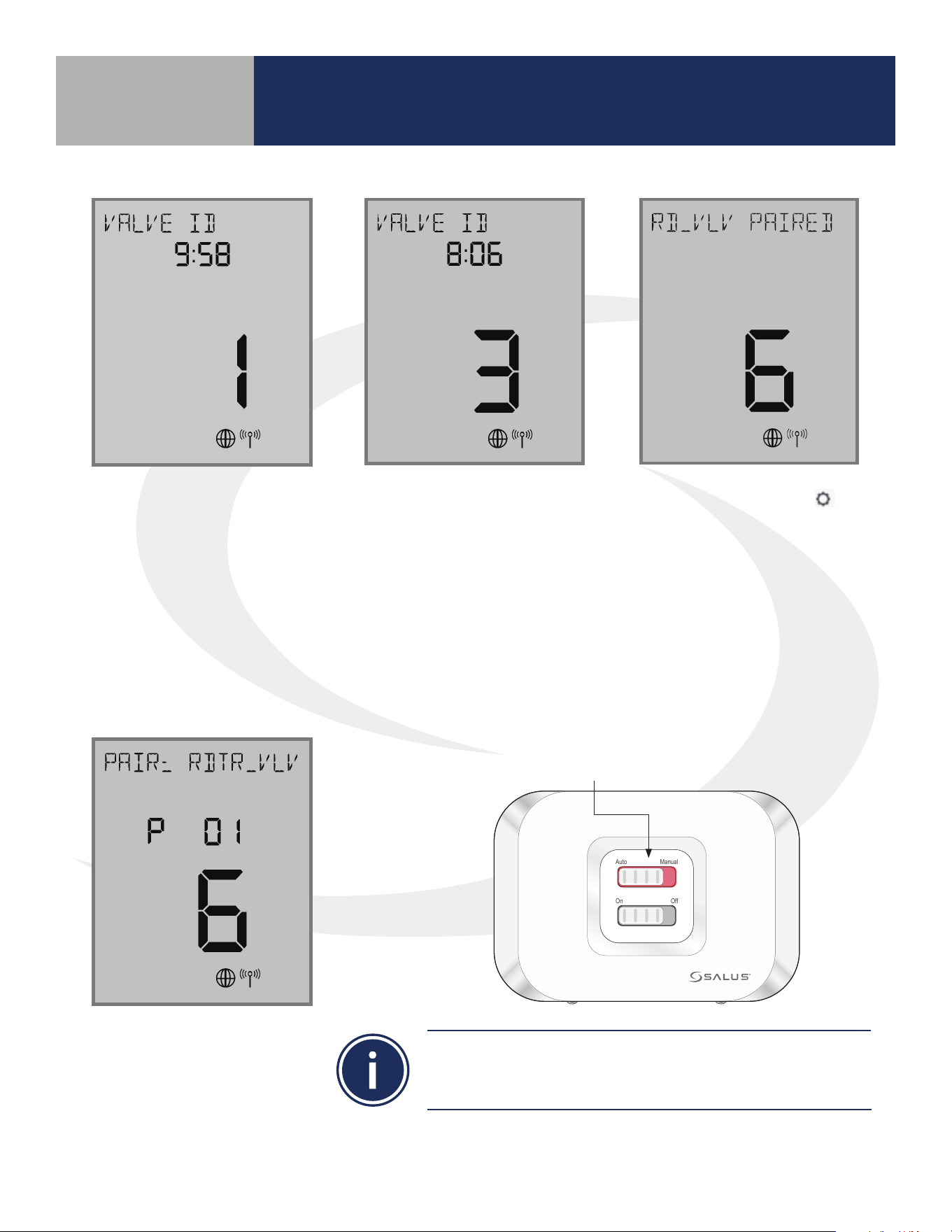
If there are any valve
actuators already on the
network, they will be paired
with the AWRT10RF.
As each ARV/AVA Valve
Actuator joins the network,
it is paired with the AWRT
Thermostat and the valve
ID number displayed on the
screen will increment. Once
paired, the LED on the valve
actuator will turn o.
If the user presses the
key, the timer times out or
6 valves have been paired,
the display will show the
total number of valves
paired for 3 seconds before
going to the parameter
setup mode.
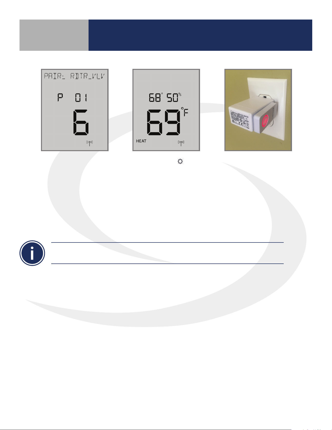
In parameter setup mode,
the AWRT10RF Thermostat
starts with P 01 (displayed
with RDTR_VLV ashing)
LED is solid red.
Auto Manual
On Off
If an AX10RF Receiver congured as RX1 has joined the
network, it will automatically be paired with the AWRT and the
LED backlight on the Auto/Manual switch will stay solid red.
Pairing with Wireless Devices Using
SG888ZB Gateway (w/ Internet Connection)
Section 5.0
18
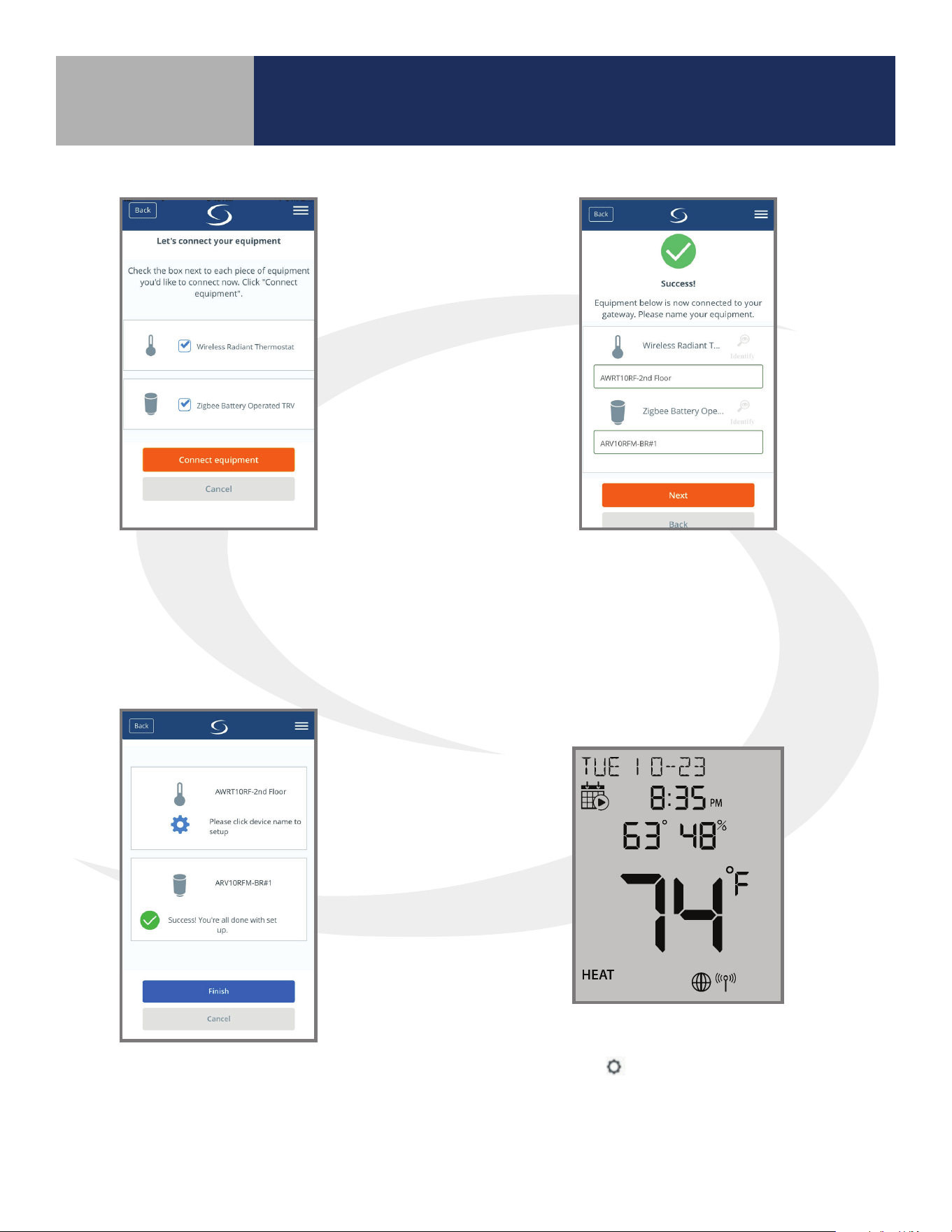
Step 5. Select “Wireless Radiant
Thermostat” and “Zigbee Battery Operated
TRV”, checking the boxes. Press “Connect
equipment”. The LED ring on the SG888ZB
Gateway will return to a steady blue.
Step 6. Give the AWRT10RF Thermostat and
each ARV/AVA Actuator a descriptive name,
dierentiating it from others in the network.
Press “Next”. If the AWRT is in parameter setup
mode when the “Next” button is pressed, it will
go to the Home screen.
Step 7. Press “Finish” to complete the
connection to the SALUS Smart Home
application.
Step 8. Press the key to exit parameter setup and
go to the Home Screen. The display shows the current
date & time, target temperature, relative humidity,
network/internet status and room temperature.
Pairing with Wireless Devices Using
SG888ZB Gateway (w/ Internet Connection)
Section 5.0
19
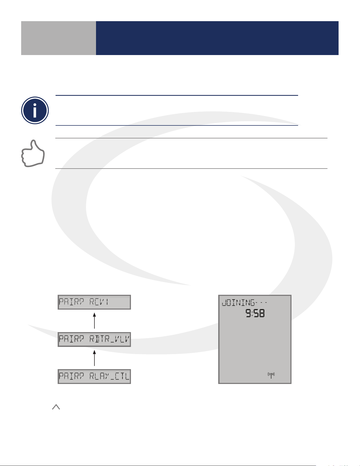
• This pairing procedure is only used when direct control of an AX10RF Receiver by the
AWRT10RF Thermostat is desired.
• Each system will support only one AX10RF congured as RX1 and one congured as RX2.
This conguration is typical in boiler systems in which there is only one thermostat in the system such
as a single steam heating loop or single forced circulation, hot water loop. For systems with multiple
zones, a zone relay controller such as the SALUS AKL Series is recommended.
Before starting the pairing process, be sure that the AX10RF Receiver is installed as shown in the
installation instructions included with the device.
• The switch on the inside cover must be congured to RX1
• The LED backlight on the Auto/Manual switch of the AX10RF Receiver should be ashing red
• The Auto/Manual switch of the AX10RF Receiver should be in the AUTO position
• The SG888ZB Gateway must be powered with solid blue LED indication that it is connected to
the internet
• The AWRT10RF Thermostat should be powered up and ashing PAIR? RLAY_CTL
JOINING- - - will be displayed with a 10
minute countdown timer and a ashing
network status indicator.
Step 1. On the AWRT10RF Thermostat,
press
until PAIR? RCV1 is displayed.
Press SELECT.
Pairing with Wireless Devices Using
SG888ZB Gateway (w/ Internet Connection)
Section 5.0
5.3 – Pairing with AX10RF Receiver for Boiler Switching (RX1)
20
Step 2. Open the SALUS Smart Home mobile application and select the drop-down menu from
the upper right side of the screen:
Equipment
Add New Equipment Scan for Equipment
Step 3. Click the “Scan for equipment” button. The SG888ZB Gateway will ash red as it searches
for devices.
Auto Manual
On Off
When the AX10RF Receiver joins
the network, the red LED backlight
on the Auto/Manual Switch will
turn steady on.
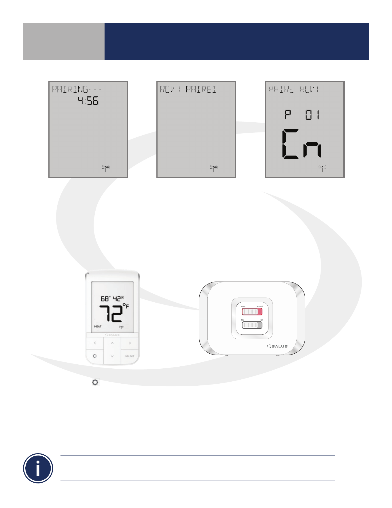
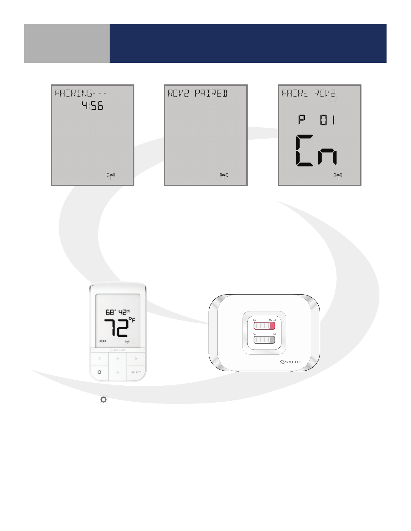
Once the AWRT10RF Thermostat
joins a network, the
icon will
stop ashing and the network
channel will be displayed briey.
The home screen will show
PAIRING- - - with a 10-Minute
countdown timer as the
AWRT10RF Thermostat looks for
an RX1 device.
After pairing is complete,
a conrmation screen
is displayed on the
AWRT10RF Thermostat
for 3 seconds, then the
device will enter the
parameter setup mode.
The thermostat display will
show “PAIR: RCV1” with P
01 indicating it is in the
parameter setup mode.
“Cn” (Connected) indicates
that the AX10RF Receiver is
paired and connected.
Pairing with Wireless Devices Using
SG888ZB Gateway (w/ Internet Connection)
Section 5.0
21
Step 4. On the SALUS Smart Home
application, check the boxes for both the
AWRT10RF Thermostat and the AX10RF
Receiver. Press “Connect equipment”.
Step 5. Enter a descriptive name for each device.
Press “Next” to continue. Since the receiver is
already paired, when the AWRT10RF Thermostat
is renamed it will immediately go to the home
screen, ending parameter setup
Step 6. After naming the devices,
the application will show that set
up is complete. Press Finish to
nalize the application setup.
If you do not rename the AWRT10RF Thermostat in the
SALUS Smart Home application, the device may stay in
parameter setup mode. Press the key to exit setup.
AX10RF(RX1)
AWRT10RF-1
AX10RF(RX1)
AWRT10RF-1
Pairing with Wireless Devices Using
SG888ZB Gateway (w/ Internet Connection)
Section 5.0
22
• This pairing procedure is only used when direct control of an AX10RF Receiver by the AWRT10RF
Thermostat is desired.
• Each system will support only one AX10RF congured as RX1 and one congured as RX2. These two
congurations can be used together to provide boiler switching and zone valve operation.
JOINING- - - will be displayed with a 10
minute countdown timer and a ashing
network status indicator.
Step 1. On the AWRT10RF Thermostat,
press
until PAIR? RCV2 is displayed.
Press SELECT.
Pairing with Wireless Devices Using
SG888ZB Gateway (w/ Internet Connection)
Section 5.0
5.4 – Pairing with AX10RF Receiver for Zone Valve Switching (RX2)
Before starting the pairing process, be sure that the AX10RF Receiver is installed as shown in
the installation instructions included with the device.
• The switch on the inside cover must be configured to RX2
• The LED backlight on the Auto/Manual switch of the AX10RF Receiver should be flashing red
• The Auto/Manual Switch of the AX10RF Receiver should be in the AUTO position
• The SG888ZB Gateway must be powered with solid blue LED indication that it is connected
to the internet
• The AWRT10RF Thermostat should be powered up and flashing PAIR? RLAY_CTL
Step 2. Open the SALUS Smart Home mobile application and select the drop-down menu from
the upper right side of the screen:
Equipment
Add New Equipment Scan for Equipment
23
Auto Manual
On Off
When the AX10RF Receiver joins the network, the red LED
backlight on the Auto/Manual Switch will turn steady on.
Once the AWRT10RF Thermostat
joins a network, the
icon will
stop ashing and the network
channel will be displayed briey.
The home screen will show
PAIRING- - - with a 10-Minute
countdown timer as the
AWRT10RF Thermostat looks for
an RX2 device.
After pairing is complete,
a conrmation screen
is displayed on the
AWRT10RF Thermostat
for 3 seconds, then the
device will enter the
parameter setup mode.
The thermostat display
will show PAIR: RCV2 with
P 01 indicating it is in the
parameter setup mode.
Cn (Connected) indicates
that the AX10RF Receiver is
paired and connected.
Pairing with Wireless Devices Using
SG888ZB Gateway (w/ Internet Connection)
Section 5.0
Step 3. Click the “Scan for equipment” button. The SG888ZB Gateway will ash red as it searches
for devices.

24
Step 4. On the SALUS Smart Home
application, check the boxes for both the
AWRT10RF Thermostat and the AX10RF
Receiver. Press “Connect equipment”.
Step 5. Enter a descriptive name for each device.
Press “Next” to continue. Since the receiver is
already paired, when the AWRT10RF Thermostat
is renamed it will immediately go to the home
screen, ending parameter setup.
Step 6. After naming the devices,
the application will show that set
up is complete. Press Finish to
nalize the application setup.
If you do not rename the AWRT10RF Thermostat in the
SALUS Smart Home application, the device may stay in
parameter setup mode. Press the key to exit setup.
AX10RF(RX2)
AWRT10RF-1
AX10RF(RX2)
AWRT10RF-1
Pairing with Wireless Devices Using
SG888ZB Gateway (w/ Internet Connection)
Section 5.0
25
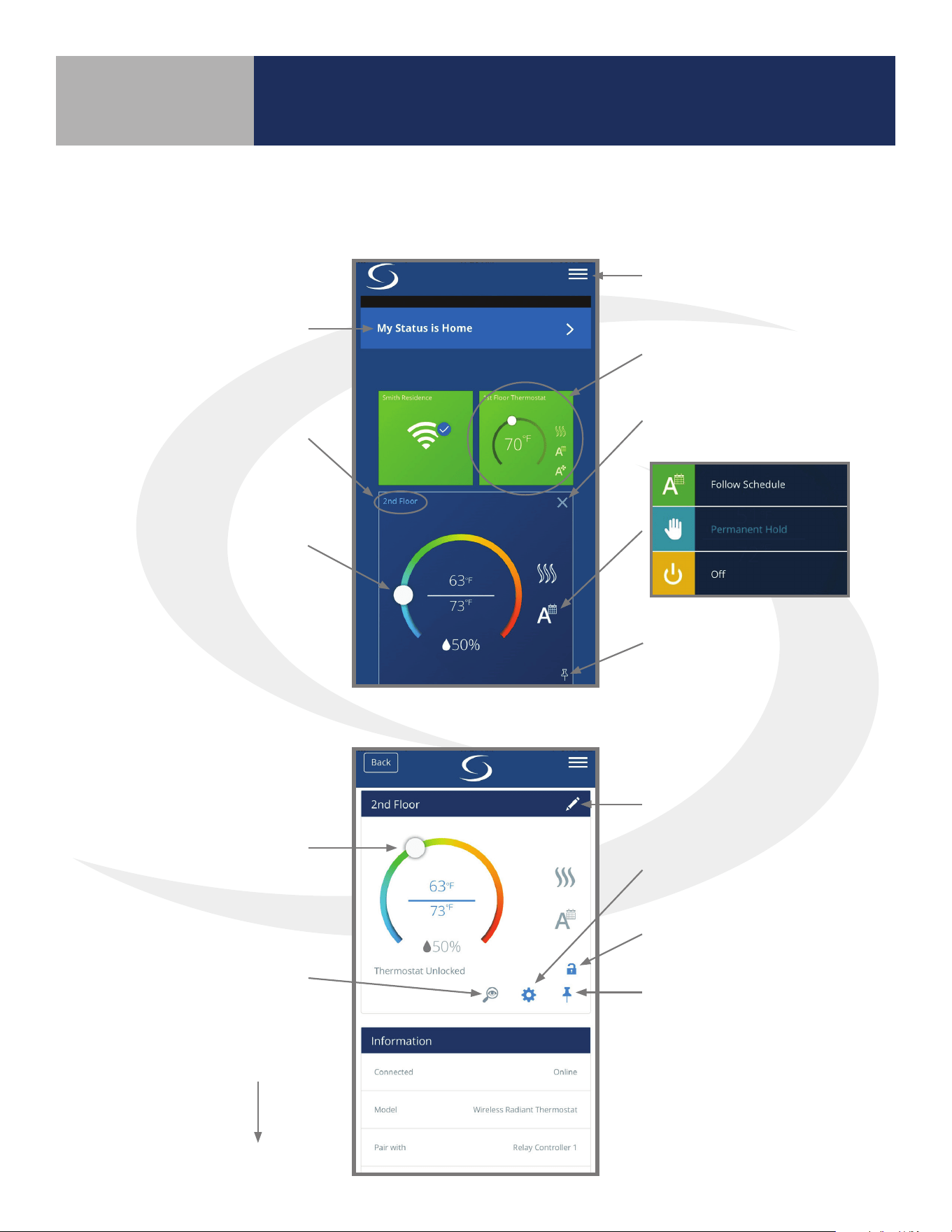
SALUS Smart Home Application
Menu
Choose Thermostat
Close Thermostat
Pin to Home Screen
Choose Status
Thermostat Options
Adjust
Rename Device
More Settings
Lock Thermostat
Pin to Home Screen
Adjust Setpoint
Identify Mode
Scroll Down
to Edit Schedule
Section 6.0
SALUS Smart Home Application: The following illustrates the dashboard and control panel for the
Wireless Radiant Thermostat in the SALUS Smart Home Application on a mobile device or computer.
Thermostat Options: Press Thermostat Options to advance to the screen below.
26
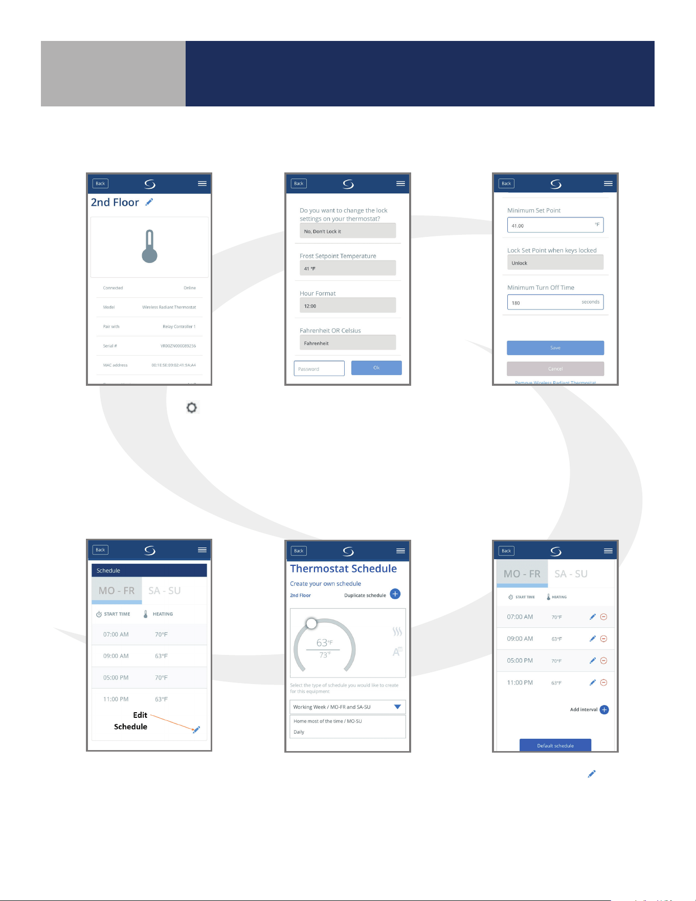
Step 1. Choose the
icon to access parameter
settings. Scroll down to
see the available settings.
Step 2. Parameters listed
can be changed without a
password. Enter “49” in the
password eld and press “Ok”
to access advanced options.
Step 3. After
making parameter
adjustments, press
the “Save” button
6.2 – Schedule Setup
Step 1. Scroll down on the
Thermostat options menu to
see default schedule. Choose
the edit icon at the bottom to
customize the schedule.
Step 2. Choose from
the 3 schedule types on
the drop-down menu
and scroll down to edit
the schedule.
Step 3. Select the
icon
to adjust the start time
or temperature for any
interval. To add an interval,
use the “Add interval” icon.
SALUS Smart Home Application
Section 6.0
6.1 – Parameter Settings
27
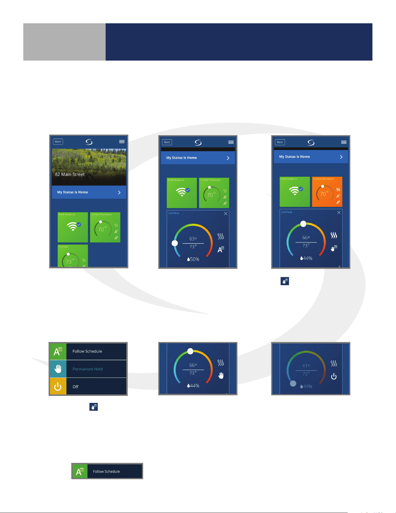
To make changes to the
thermostat settings using
the SALUS Smart Home
Application, simply choose the
icon from the home screen.
To change the current
temperature setpoint,
move the dial to the
desired temperature.
The
icon indicates
temporary temperature hold
that will end when the next
scheduled period begins.
Selecting the icon will
display the menu shown
providing 3 options.
To change the current
temperature setpoint,
move the dial to the
desired temperature.
The
icon indicates a
temporary temperature hold
that will end when the next
scheduled period begins.
Pressing “Permanent Hold” will
display the icon shown above
and will keep the setpoint
at the current temperature,
ignoring schedule changes.
Pressing “O” will
cause the AWRT10RF
Thermostat to stop
calling for heat until it
is turned back on.
Pressing will have the AWRT10RF Thermostat go
back to the programmed schedule, starting at the current day and time.
The following instructions describe operation of the AWRT10RF Thermostat using the SALUS Smart
Home Application to make adjustments from any location.
SALUS Smart Home Application
Section 6.0
6.3 – Remote Operation
28
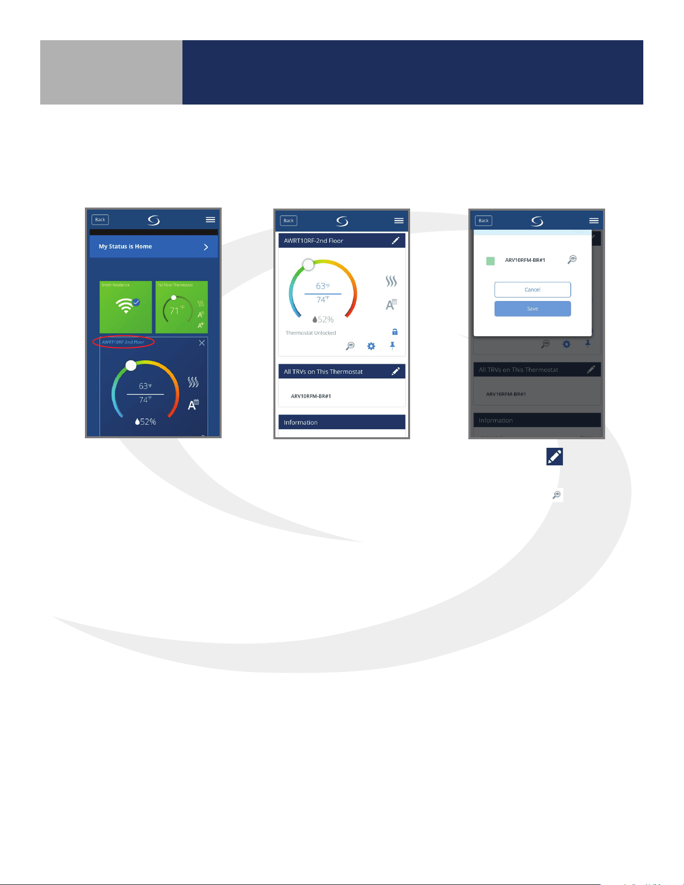
Choose the thermostat
that controls the
Radiator Valve
Actuators. Then select
the thermostat name
(circled in red).
The following instructions describe identication and/or disabling of ARV/AVA Radiator Valve
Actuators. It is not recommended to disable or enable radiator valve actuators without visual
access to the devices.
The setting screen will
show all thermostatic
radiator valves (TRVs)
associated with the
AWRT10RF Thermostat.
Choosing the
symbol
displays the list of TRVs.
Choosing the
icon will
cause the LED indicator on
the associated ARV10RFM
or AVA10M30RF Radiator
Valve Actuator to ash
green, identifying the
valve.
To disable an ARV/AVA Radiator Valve Actuator, select the green box, which will remove the green
indication, and press “Save”. To enable an ARV/AVA Radiator Valve Actuator, select the gray indicator
box, which will turn the indicator green, and press “Save”.
SALUS Smart Home Application
Section 6.0
29
Pairing with Wireless Devices using AC10RF
Coordinator (w/o Internet Connection)
Section 7.0
System Conguration without internet connection
Prior to using the AC10RF Coordinator on a system with no internet connection, update the
rmware version as follows:
1. Use a computer with an internet connection that meets the following requirements:
2. Go to the SALUS Software Tools web page: www.salusinc.com/tools.html
3. Download and run the Coordinator Update Tool to update the AC10RF Coordinator by
following the onscreen instructions.
4. Insert the AC10RF Coordinator into a USB port on the computer when prompted to do so
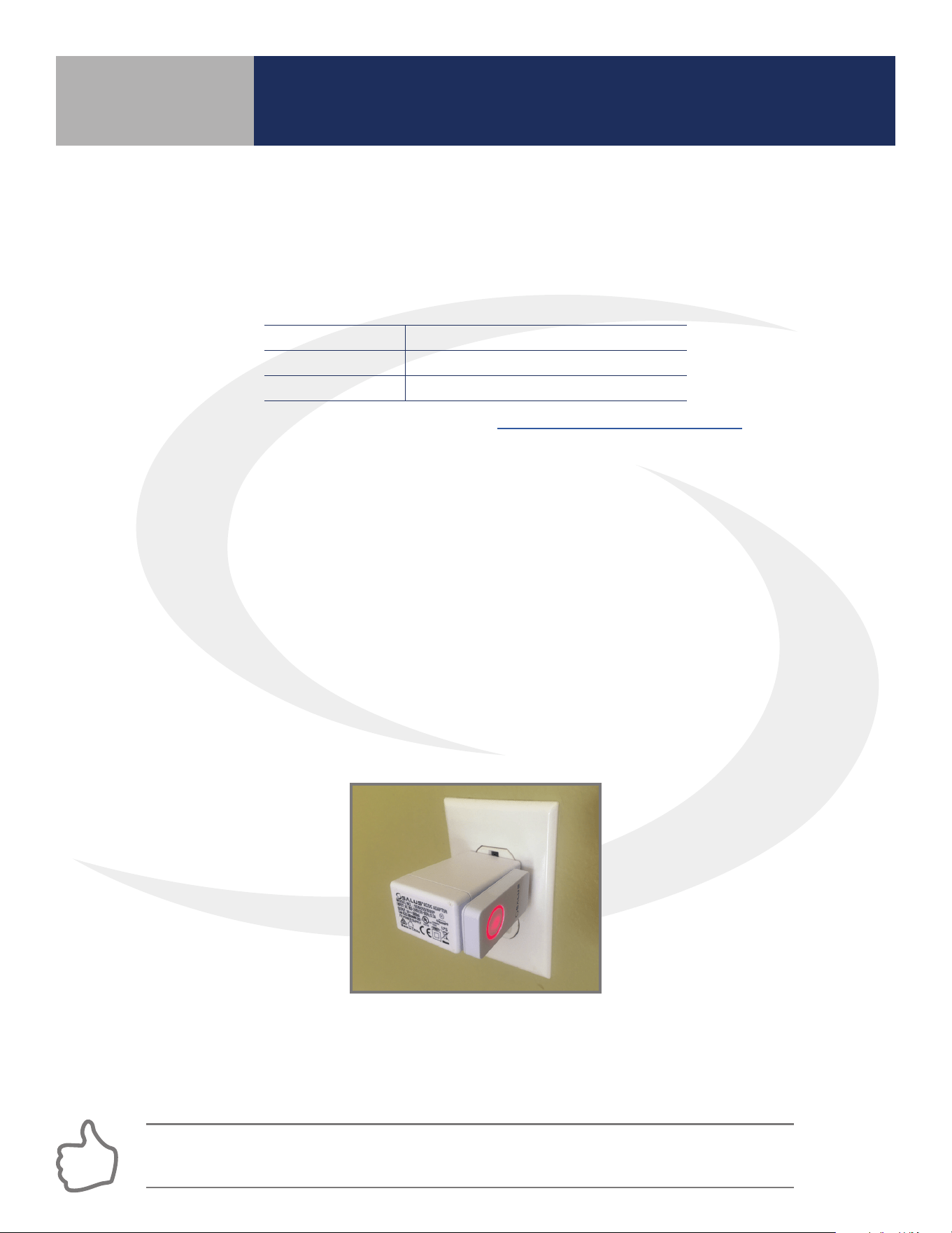
After updating the rmware, insert the AC10RF Coordinator into the provided power adapter and
plug the two devices into an AC outlet. Verify that the LED is solid red.
7.1 – Pairing with AKL01/04/06PRF and
AKL08RF Relay Controllers
Before pairing, the AKL Series Relay Controller and optional AX10RF Receiver (if desired) must be
installed and powered in accordance with installation instructions included with these devices.
• The Network Status LED on the AKL Relay controller should be ashing and,
• if an AX10RF Receiver is used, the LED backlight on the Auto/Manual switch of this device
should be ashing red.
Step 1. Press and hold the lighted red button on the AC10RF Coordinator for 5 seconds until the
LED begins ashing, to begin pairing. When the network status LED on the AKL Relay Controller and
the backlight on the Auto/Manual switch of the AX10RF (if used) stop ashing, they have joined the
network and you are ready to pair the AWRT Wireless Radiant Thermostat.
COMPUTER PC Mac
OPERATING SYSTEM Windows 8 or later OSX 10.10 or later
USB PORT Type A Type A
If the network status LED on the AKL Relay Controller continues blinking, turn o the power
to the device for 10 seconds.
30
Step 2. Once the AKL Relay Controller is connected (network status LED is no longer ashing),
briey press the pairing button (shown above) on the relay controller. Zone LEDs on the AKL Relay
controller will illuminate indicating the ID number of the device. This number will be used to set up
thermostats to address the correct relay controller.
ID #
Zone
1
Zone
2
Zone
3
Zone
4
1
2
3
4
5
6
7
8
9
0
AKL Relay
Controller ID
• When zone LEDs are illuminated in ID mode, the illuminated zone outputs will be activated.
• The AKL01PRF Relay Controller uses the pulse codes shown above to identify the ID number. A short
pulse = 1 and a long pulse = 3. Add the pulse values of all pulses for the ID of the relay controller.
AKL01 Relay Controller ID#
Zone LED Pulse Code
ID #
LED Pattern
Short = , Long =
1
2
3
4
5
6
7
8
9
AKL01/04/06PRF Relay Controller Pairing Button
AKL08RF Relay Controller Pairing Button
The display will show JOINING- - - with a 10
minute countdown timer to show how much
time is available to join a network. The
icon will ash at the bottom of the screen
indicating that the thermostat is searching
for a network to join.
Step 3. After the AWRT10RF Thermostat
completes its boot sequence, the Relay
Controller (RLAY_CTL) will be displayed and
ashing. If another device is displayed, use the
or keys to display the correct device.
Press SELECT to start the pairing process.
Pairing with Wireless Devices using AC10RF
Coordinator (w/o Internet Connection)
Section 7.0
31
When the AWRT10RF Thermostat has
found all controllers in the network, it
will display the default relay controller
value (1) and the default zone value (1).
If there is more than 1 relay controller on
the network, the left value
will
ash. If there is only one relay controller,
the right-hand value for
will ash.
Step 4. Use the
and
keys to change the
CONTROLLER value, then
the
or key to switch to
the ZONE.
Step 6. Press the
key to exit
parameter setup and go to the Home
Screen. The display shows the current
date & time, target temperature,
relative humidity, network/internet
status and room temperature.
The AWRT10RF Thermostat
will enter parameter setup
mode, starting with parameter
P 01. The current device type
along with the Zigbee channel
number will be displayed.
Once the AWRT10RF Thermostat has joined the network, SCANNING-
- - is displayed with a 10-minute countdown timer showing the time
allowed to nd all the relay controllers on the network
Step 5. Use the and keys
to change the ZONE value, then
press SELECT. The AWRT10RF
Thermostat will then display
PAIRING- - - as it associates with
the selected controller and zone.
When paired, RLY_CTL
PAIRED will be displayed
briey along with the
CNTRLR value and
ZONE value.
Step 7. Press and hold the lighted ashing button on the AC10RF for 5 seconds until the red LED stops
ashing. The AKL Relay Controller and AWRT10RF Thermostat are now paired.
Pairing with Wireless Devices using AC10RF
Coordinator (w/o Internet Connection)
Section 7.0
32
Before beginning the pairing process, it is important to be sure that the ARV10RFM or AVA10M30RF
Radiator Valve Actuator was installed and adapted properly as detailed in their installation instructions.
The following is a review of those instructions.
ARV/AVA Radiator Valve Actuator Installation Review
Step 1. Install the batteries and wait until the LED is solid red before installing the actuator on the radiator
valve. Remember that the actuator should only be nger tight on the valve. Using pliers or other tools can
damage the device.
Step 2. After attaching the actuator to the valve, press any of the buttons to initialize the ARV/AVA Radiator
Valve Actuator. This process may take several minutes, and the valve may continue to initialize after the light is
no longer illuminated.
ARV/AVA Radiator Valve Actuator Pairing Procedure
Before pairing, the ARV/AVA Radiator Valve Actuator(s) and AX10RF Receiver (if desired) must be powered in
accordance with the installation instructions included with the devices.
• The LED indicator on the ARV/AVA Radiator Valve Actuator(s) should be o with NO MOTOR ACTIVITY.
• If and AX10RF Receiver is used, the LED backlight on the Auto/Manual switch of this device should be
ashing red and the switch should be in the AUTO position
Step 1. Press and hold the lighted red pairing button on the AC10RF Coordinator for 5 seconds, until the LED
begins ashing.
DO NOT BEGIN pairing with the ARV/AVA Radiator Valve Actuator unless the light is out and there is NO
MOTOR ACTIVITY. Listen closely to the Valve Actuator to be sure it is not operating before proceeding.
A maximum of 6 ARV10RFM or AVA10M30RF Radiator Valve Actuators
can be paired with each AWRT10RF Wireless Radiant Thermostat.
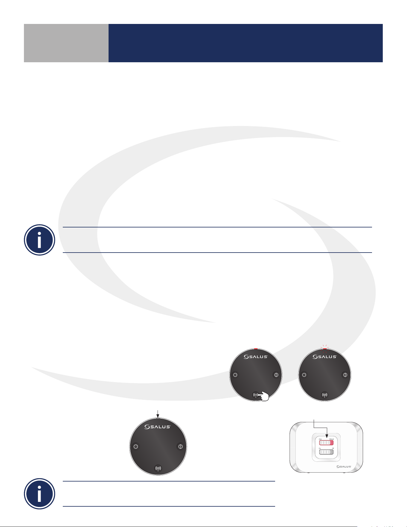
10 seconds The LED indicator will ash red.
Step 2. Press and hold the pairing button until the LED
indicator begins ashing (approximately 10 seconds) on
each ARV/AVA Radiator Valve Actuator to be associated
with the AWRT Wireless Radiant Thermostat.
LED is o.
Auto Manual
On Off
LED is solid red.
When the ARV/AVA valve
actuators join the network,
the LED indicator on the
Radiator Valve Actuator
will turn o.
If an AX10RF Receiver
joins the network, the
LED backlight on the
Auto/Manual switch
will stay solid red.
Pairing with Wireless Devices using AC10RF
Coordinator (w/o Internet Connection)
Section 7.0
7.2 – Pairing with ARV10RFM or AVA10M30RF Radiator Valve
Actuators
33
Once the AWRT10RF Thermostat joins a network, the icon will
stop ashing and the network channel will be briey displayed.
After that, PAIRING- - - is displayed with a 10-minute countdown
timer showing the time allowed for the remaining pairing steps.
Step 3. Use the and
keys on the AWRT10RF
Thermostat to switch from
RLAY_CTL to RDTR_VLV. Press
SELECT to initiate pairing.
The AWRT Thermostat
will display the Valve
ID number and a 10-
minute timer showing
how much time is left to
nish pairing.
As each ARV/AVA Valve
Actuator is paired with
the AWRT Thermostat,
the ID number displayed
on the screen will
increment.
If the user presses the
key, the timer times
out or 6 valves have
been paired, the display
will read “RD_VLV
PAIRED” for 3 seconds.
JOINING- - - is displayed with a 10 minute countdown
timer to show the remaining time available to
complete the next steps. The
icon will ash at the
bottom of the screen indicating that the thermostat is
searching for a network to join.
Pairing with Wireless Devices using AC10RF
Coordinator (w/o Internet Connection)
Section 7.0
34
After 3 seconds, the
AWRT10RF Thermostat will
enter the parameter setup
mode, starting with P 01
(displayed with RDTR_VLV
ashing). The number of
radiator valves connected
is also displayed.
Step 4. Press the
key
to exit parameter setup
and go to the home
screen. The display shows
target temperature,
relative humidity, room
temperature, operation
mode and network status.
Step 5. Press & hold
the ashing red pairing
button on the AC10RF
Coordinator for 5
seconds to complete the
pairing process.
The AWRT Wireless Radiant Thermostat defaults to Non-programmable mode and doesn’t show
time or date. For details on changing to programmable mode, see Section 8, Parameter Setup.
Pairing with Wireless Devices using AC10RF
Coordinator (w/o Internet Connection)
Section 7.0
35
• This pairing procedure is only used when direct control of an AX10RF Receiver by the
AWRT10RF Thermostat is desired.
• Each system will support only one AX10RF congured as RX1 and one congured as RX2.
The following conguration is typical in boiler systems in which there is only one thermostat in the
system such as a single steam heating loop or single forced circulation, hot water loop. For systems
with multiple zones, a zone relay controller such as the SALUS AKL Series is recommended.
Before starting the pairing process, be sure that the AX10RF Receiver is installed as shown in the
installation instructions included with the device.
• The switch on the inside cover must be congured to RX1.
• The LED backlight on the Auto/Manual switch of the AX10RF Receiver should be ashing red.
• The Auto/Manual switch of the AX10RF Receiver should be in the AUTO position.
• The AWRT10RF Thermostat should be powered up and ashing PAIR? RLAY_CTL.
JOINING- - - will be displayed with a 10
minute countdown timer and a ashing
network status indicator.
Step 2. On the AWRT10RF Thermostat,
press
until PAIR? RCV1 is displayed.
Press SELECT.
Step 1. Press and hold the lighted red pairing
button on the AC10RF Coordinator for 5
seconds, until the LED begins to ash.
Pairing with Wireless Devices using AC10RF
Coordinator (w/o Internet Connection)
Section 7.0
7.3 – Pairing with AX10RF Receiver for Boiler Switching (RX1)
36
Once the AWRT10RF
Thermostat has joined the
network, the screen will
show PAIRING- - - with a 5
minute countdown timer.
After pairing is complete,
a conrmation screen
is displayed for 3
seconds, the AWRT10RF
Thermostat enters the
parameters set up mode.
The display will show
PAIR: RCV1 with P
01 indicating it is in
the parameter set up
mode. Cn (Connected)
indicates that the
AX10RF Receiver is
paired and connected.
Step 3. Press the
key to exit setup and start normal operation. The AWRT10RF Thermostat display will
show the current room temperature, target temperature, relative humidity along with indicators for the
temperature mode and network status. The red LED backlight on the Auto/Manual switch will not be
ashing.
Step 4. Press the pairing button on the AC10RF Coordinator to exit pairing mode and
begin normal operation.
Auto Manual
On Off
The AWRT Wireless Radiant Thermostat defaults to Non-programmable mode and doesn’t show
time or date. For details on changing to programmable mode, see Section 8, Parameter Setup.
Pairing with Wireless Devices using AC10RF
Coordinator (w/o Internet Connection)
Section 7.0
37
Each system will support only one AX10RF congured as RX1 and one congured as RX2. These two
congurations can be used together to provide boiler switching and zone valve operation.
JOINING- - - will be displayed with a 10
minute countdown timer and a ashing
network status indicator.
Step 2. On the AWRT10RF Thermostat,
press
until PAIR? RCV2 is displayed.
Press SELECT.
Before starting the pairing process, be sure that the AX10RF Receiver is installed as shown in the
installation instructions included with the device.
• The switch on the inside cover must be congured to RX2.
• The LED backlight on the Auto/Manual switch of the AX10RF Receiver should be ashing red.
• The Auto/Manual switch of the AX10RF Receiver should be in the AUTO position.
• The AWRT10RF Thermostat should be powered up and ashing PAIR? RLAY_CTL.
Step 1. Press and hold the lighted red pairing
button on the AC10RF Coordinator for 5
seconds, until the LED begins to ash.
Pairing with Wireless Devices using AC10RF
Coordinator (w/o Internet Connection)
Section 7.0
7.4 – Pairing with AX10RF Receiver for
Zone Valve Switching (RX2)
38
Once the AWRT10RF
Thermostat has joined the
network, the screen will
show PAIRING- - - with a 5
minute countdown timer.
After pairing is complete,
a conrmation screen
is displayed for 3
seconds, the AWRT10RF
Thermostat enters the
parameters set up mode.
The display will show
PAIR: RCV2 with P
01 indicating it is in
the parameter set up
mode. Cn (Connected)
indicates that the
AX10RF Receiver is
paired and connected.
Step 3. Press the
key to exit setup and start normal operation. The AWRT10RF Thermostat
display will show the current date & time, target temperature and current room temperature along
with indicates for the temperature mode, internet and network status. The red LED backlight on
the Auto/Manual switch will not be ashing.
Step 4. Press the pairing button on the AC10RF Coordinator to exit pairing mode and
begin normal operation.
Auto Manual
On Off
Pairing with Wireless Devices using AC10RF
Coordinator (w/o Internet Connection)
Section 7.0
39
Settings: Press the key
to enter settings menu.
Available settings are
shown on the Settings
Chart. Use the
or
keys to scroll through
available settings.
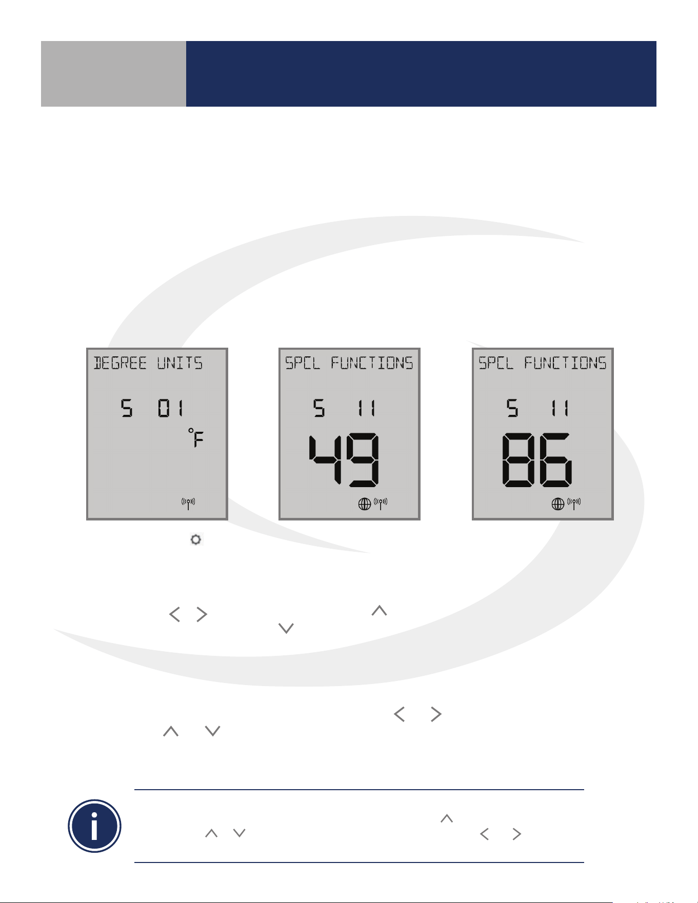
Time/Date Functions: If
S 02 through S 10 are not
accessible, change the
S 11 value to “49” on the
display using the
or
keys and press enter.
Change item P02 to YES
to enable thermostat
programming.
Reset to Factory
Settings: To reset the
AWRT10RF Thermostat to
factory settings, change
the S 11 value to “86” and
choose “Y” to reset.
Generally, once in settings or parameter setup mode, use
and to move between settings and
parameters, and
and to change setting or parameter values. Use SELECT to conrm changes.
The table on the following page titled “AWRT10RF Wireless Radiant Thermostat Settings” lists the
settings available from the thermostat screen and keypad.
Installers can access parameters on the AWRT10RF using the SALUS Smart Home application if an
SG888ZB Gateway is used and connected to the internet. Alternatively, the parameters may be
entered directly through the display and keypad on the AWRT10RF Thermostat. The following
procedure outlines parameter adjustments using the keypad. Changes made on the SALUS Smart
Home application or on the AWRT10RF Thermostat may take a few minutes to go into eect.
Before starting setup procedures, press any key to light the display and prepare the AWRT
Thermostat for input.
Scheduling functions with date and time are OFF as default for the AWRT Thermostat.
To enable the time & date display, choose S11 and push the key until 49 is displayed
(holding the or key will increment/decrement by 10). Use the and keys to go
to P02 and choose YES to enable the scheduling function.
AWRT10RF Thermostat Settings & Parameters
Section 8.0
8.1 – Parameter & Settings Adjustments using
the Display & Keypad

40
Setting # Description Options Notes
S 01 Temperature Units
°F Degrees Fahrenheit
°C Degrees Celsius
S 03 Clock Format
12-hour Example- 9:45 pm
24-hour Example:- 21:45
S 04 Daylight Savings Time
ON Automatic Daylight Savings Time Enable
OFF Automatic Daylight Savings Time Disable
S 05 Month 01-12 MM Format (DD/MM/YYYY)
S 06 Date 01-31 DD Format (DD/MM/YYYY)
S 07 Year 2018-2099 YYYY Format (DD/MM/YYYY)
S 08 Hour
00-23 HH Format (HH:MM)
12-11 am/pm HH Format (HH:MM am/pm)
S 09 Minute 00-59 MM Format (HH:MM or HH:MM am/pm)
S 10 Schedule
WK Weekly Schedule
5+2 Weekday/Weekend Schedule
DAY Daily Schedule
S11 Parameters
22 Leave Network
35 Delete Oine Devices
38 Delete Relay Controllers
49 Parameter Settings (See Parameter Table on next page)
86 Reset to Factory Settings
99 Rejoin Network
S 12 Identify Mode Press SELECT to Identify Network & Associated Device(s)
Available only when P02 Schedule is enabled
AWRT10RF Thermostat Settings & Parameters
Section 8.0
Table 8.2 – AWRT10RF Wireless Radiant Thermostat Settings
41
Para. # Function Default Range Description
P01 Pair Device
RLAY_CTL
RLAY_CTRL AKL Relay controllers: Displays controller ID & Zone number
RDTR_VLV ARV/AVA Valve Actuators: Displays total # of paired valves
RCV1 AX10RF Receiver (RX1): Cn = Connected
RCV2 AX10RF Receiver (RX2): Cn = Connected
P02 Internal Schedule N (inactive)
N (inactive) Settings S 03 through S 10 are not available
Y (active) Schedule Mode
P03
Temperature
Control
Method
AUTO
AUTO
RLAY CTL (HEAT), RCV1, RCV2 = TPI
RLAY CTRL (COOL) = DLTA 1.0°F (0.5°C)
RDTR VLV = DLTA 0.5°F (0.25°C)
TPI
TPI control is based on the current temperature dierential
(Proportional) and historical performance (Integral) to determine the
next duty cycle percentage.
DLTA 1.0/0.5
Heat turns on when T
room
= T
setpoint
– Delta, Cooling turns on when
T
room
= T
setpoint
+ Delta
DLTA 0.5/0.25
P04
Minimum
OFF Time
180 seconds 180 - 300 seconds
Minimum period that the thermostat must be o before starting a new
cycle to prevent short cycling. (TPI Only)
P08
Temperature
Oset
0.0°F or °C ±6.0°F (3.0°C) Temperature oset for current active temperature sensor
P09
Freeze
Protection
41°F (5°C)
41 to 63°F
(5 to 17°C)
Minimum allowable temperature for the system. Below the
specied temperature a heat demand will be signaled.
O
P10
Maximum Target
Temperature
95°F (35°C)
42 to 95°F
(5.5 to 35°C)
Maximum allowable temperature setting for heating and cooling mode.
P11
Minimum Target
Temperature
41°F (5°C)
41 to 94°F
(5 to 34.5°C)
Minimum allowable temperature setting for heating and cooling mode.
P15 External Sensor OFF (Disabled)
ON (Enable)
OFF (Disable)
Enable or Disable external sensor for remote sensing. “EXTERNAL” is
only displayed if P16 function is set to “AIR”.
P16
External Sensor
Function
FLR (Floor)
FLR (Floor)
or AIR
Floor temperature is used to control the room temperature based on
the room and radiant oor temperature.
Air is used when a remote sensor is used in place of the internal
thermostat sensor.
P17
Maximum Floor
Temperature
81°F (27°C)
52 to 95°F
(11 to 35°C)
Maximum temperature that a heat demand will be signaled. P15
must be ON and External Sensor Function must be FLR. Not
displayed for RDTR VLV.
P18
Minimum Floor
Temperature
50°F (10°C)
41 to 95°F
(5 to 35°C)
Minimum temperature that a cooling demand will be signaled.
P15 must be ON and External Sensor Function must be FLR. Not
displayed for RDTR VLV.
The table below titled AWRT10RF Wireless Radiant Thermostat Parameters lists parameters
available from the thermostat screen & keypad.
AWRT10RF Thermostat Settings & Parameters
Section 8.0
Table 8.3 – AWRT10RF Wireless Radiant Thermostat Parameters

42
Para. # Function Default Range Description
P19
Radiator Actuator
Control
ON/OFF
ON/OFF
PI
ON/OFF radiator valve control uses simple proportional control
PI radiator valve control is described in detail in the ARV/AVA
Radiator Valve Actuator manual. This parameter is only available if
P01 = RDTR VLV.
P21 Valve Protection ON
ON (enabled)
OFF (disabled)
When enabled, the radiator valve protection function periodically
operates the valve, exercising it to prevent failure. This parameter is
only available if P01 = RDTR VLV.
P25 Key Lock Source KYS+APP APP
When KYS+APP is selected, parameter P26 (Lock Setpoint) can be
activated from either the display and keypad of the AWRT10RF
Thermostat by using the SALUS Smart Home application. If APP
is chosen, parameter P26 is only available online via the mobile
application. This parameter is only available for internet connected
thermostats.
P26
Lock Setpoint
Unlock
Unlock
Lock
When set to “Lock”, the temperature setpoint cannot be changed
from the keypad without changing this parameter to “Unlock”.
AWRT10RF Thermostat Settings & Parameters
Section 8.0
Table 8.3 – AWRT10RF Wireless Radiant Thermostat Parameters
(Continued)
43
The AWRT10RF Wireless Radiant Thermostat is supplied as a non-programmable thermostat as
default. Change P02 above to Y for programmable thermostat functionality.
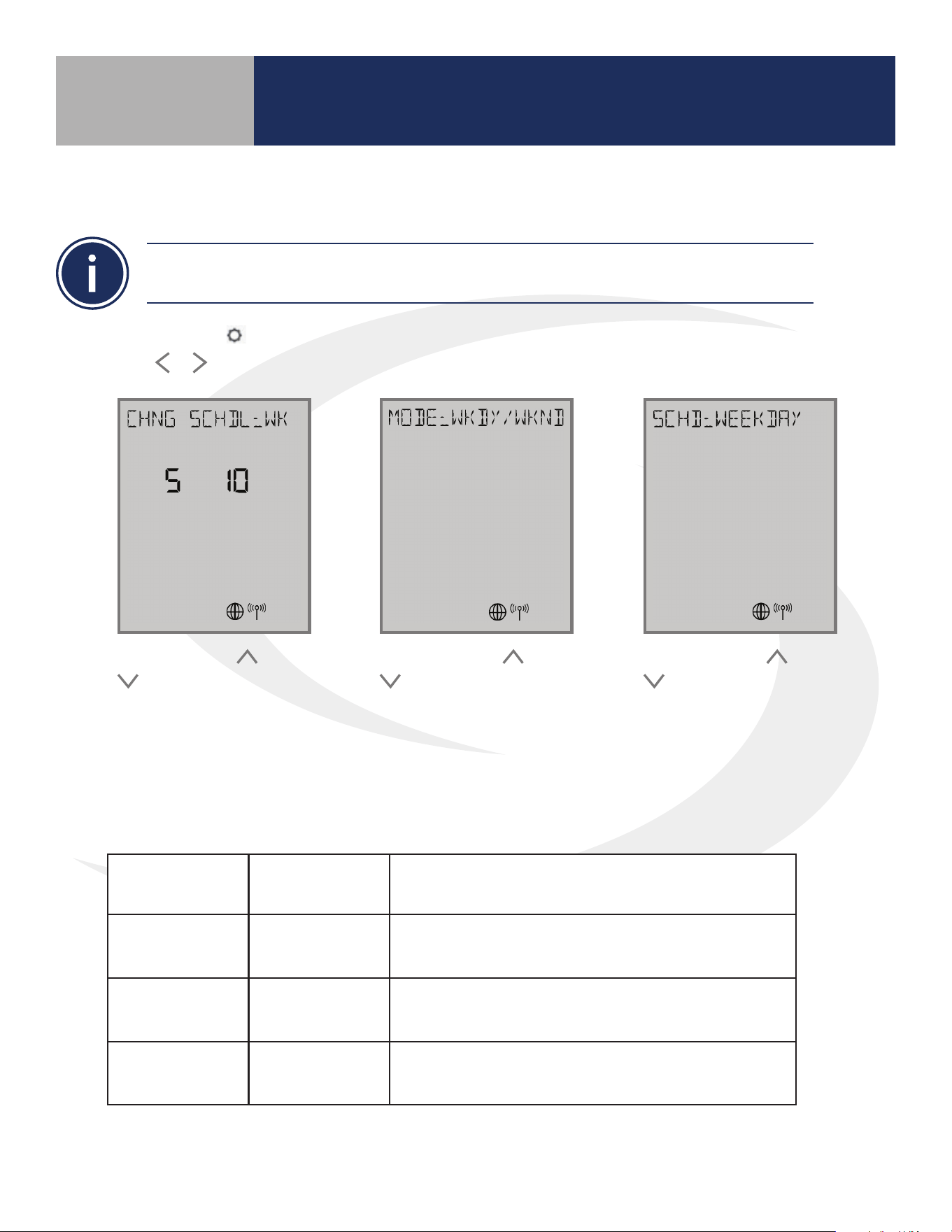
Step 1. Press the key to enter settings menu. Available settings are shown on the Settings Chart.
Use the
or keys to scroll through available settings.
Step 2. Use the and
keys to select the
schedule type. See
Schedule Option Table
below. Press SELECT.
Step 3. Use the
and
keys to change the
schedule Mode if desired.
Press SELECT.
Step 4. Use the
and
keys to change the
day or group of days for
programming. Press
SELECT.
Schedule Options
S10 Selection
Mode
Selection
Description
WK WEEKLY
Temperature schedule for entire week:
Monday through Sunday
5+2 WKDY/WKND
Temperature schedule for Weekday (Mon-Fri)
and Weekend (Sat-Sun)
DAY DAILY
Temperature schedule for each day of the week
AWRT10RF Thermostat Settings & Parameters
Section 8.0
8.4 – Schedule Setup using Display & Keypad
44
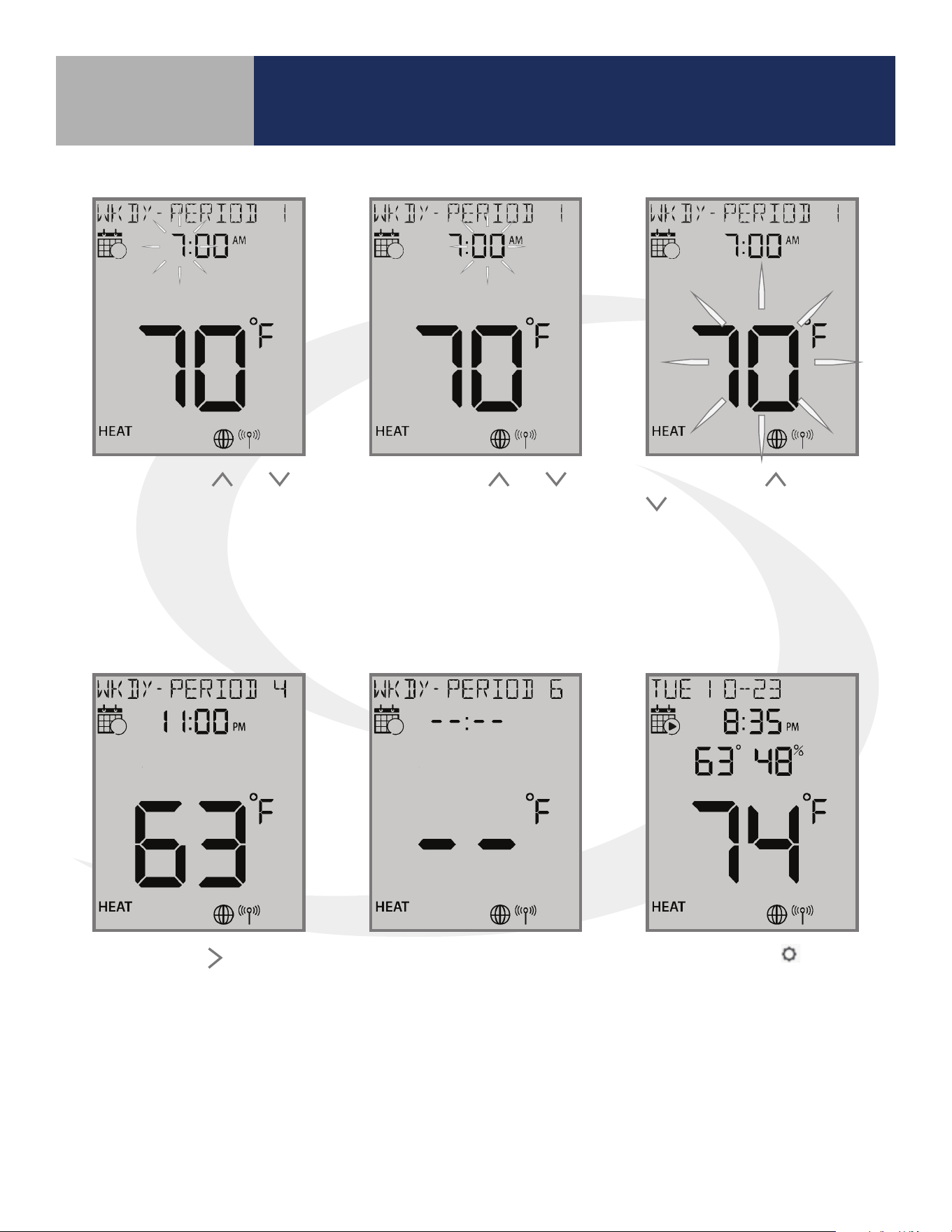
Step 5. Use the and
keys to change the hour to
begin the rst period. Press
SELECT.
Step 6. Use the
and
keys to change the minute
to begin the rst period.
Press SELECT.
Step 7. Use the
and
keys to change the
temperature to begin the
rst period. Press SELECT.
Step 8. Use the key to
switch to the next period.
Set the hour, minute and
temperature for each period
desired.
Step 9. Leave the time &
temperature elds blank “- -“
to skip periods that aren’t
required.
Step 10. Press the
key
to back out of the menu
or simply allow the setting
screen to time out after
which it will return to the
standard display screen.
AWRT10RF Thermostat Settings & Parameters
Section 8.0
45
AWRT10RF Wireless Radiant
Thermostat Operation
Section 9.0
9.1 – Setting the HVAC Mode using the Display & Keypad
9.2 – Changing the Temperature Setpoint in
Non-programmable Mode
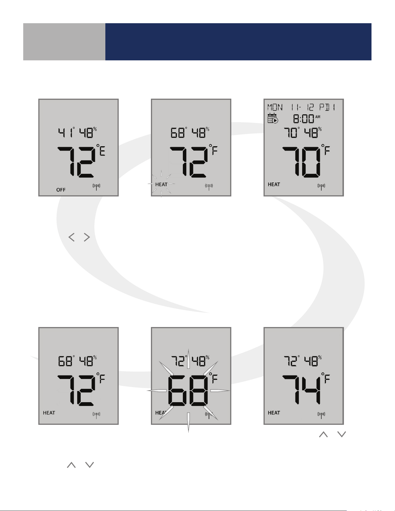
Step 1. Press any key on the
keypad to activate the backlit
display preparing it for input.
Press the
or key to toggle
between HVAC Modes (HEAT/
COOL/OFF).
The new mode setting
will ash and the current
setpoint temperature will
appear above the room
temperature display. If the
mode is OFF, the setpoint
will change to 41°F (5°C).
Step 2. Press SELECT to
accept the new heat mode.
The heat mode stops
ashing. If the AWRT10RF
Thermostat is setup as
programmable, the current
time & date will be displayed
as well as the schedule icon.
Step 1. Press any key on the
keypad to activate the backlit
display to prepare for input.
Press the
or key to
adjust the target temperature
The positions of the setpoint
temperature and the current
room temperatures are
swapped on the display.
Step 2. Press the
or
keys to adjust the target
setpoint. The new setpoint
will take aect once the
display stops ashing.
46
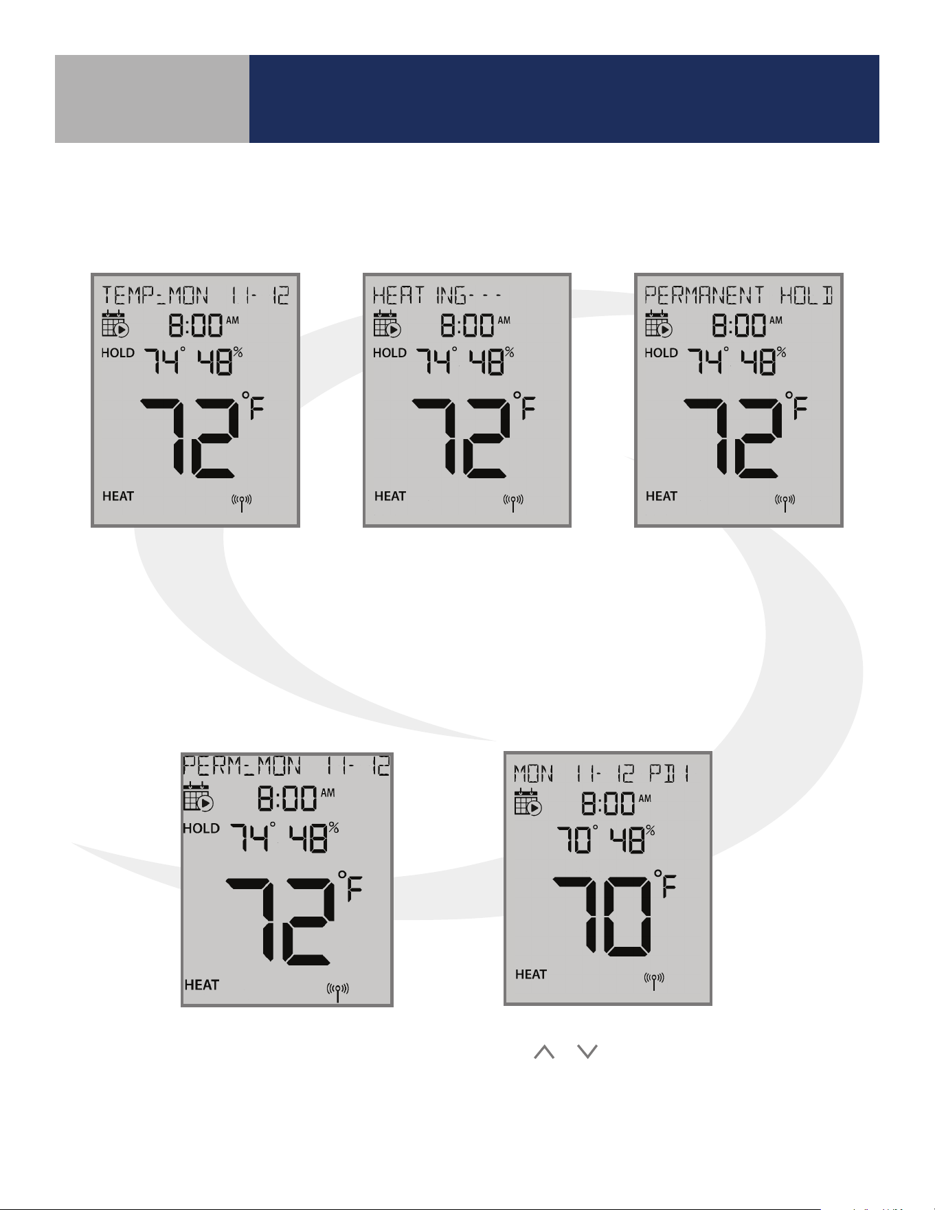
If the setpoint is changed
while a schedule is running,
the AWRT10RF display will
display “TEMP: DAY MM-DD”
and show “HOLD”, indicating
it is in temporary hold until
the next schedule period.
If the temperature
change results in a heat
demand, the text above
will alternate between
“Temp: DAY MM-DD” and
HEATING- - -.
Pressing SELECT while the
target setpoint is ashing
will toggle “PERMANENT
HOLD” which indicates the
target temperature will
remain as set, ignoring
scheduled changes, until
changed by the user.
While in Permanent Hold,
“PERM: DAY MM-DD” will be
displayed along with “HOLD”
below the calendar icon.
To return to the programmed schedule, use
the
or keys to set the temperature to
the scheduled temperature. If “PERMANENT
HOLD” is displayed, use the select key to
toggle it o.
AWRT10RF Wireless Radiant
Thermostat Operation
Section 9.0
9.3 – Overriding Scheduled Temperature using
the Display & Keypad
47
AWRT10RF Wireless Radiant Thermostat -
Troubleshooting
Section 10.0
Error Message Description Corrective Action
ER:VA DEVICE
Thermostatic Radiator Valve
(TRV) hardware issue.
Remove the ARV10RFM or AVA10M30RF Actuator from the radiator
valve and check to see if the valve plunger is operating
If the plunger is working correctly, try resetting the actuator as
described in Section 8
ER:XSNSR OPEN
External Sensor Open – Not Connected:
Parameter P15 is enabled for external sensor
but no sensor connection is detected.
If no external sensor is used, disable Parameter P15.
If an external sensor is used, check continuity of the circuit.
Check for wire damage or defective sensor.
ER:XSNSR SHORT
Externa Sensor Short:
Control senses no resistance
across sensor.
Check for wire damage creating sensor lead short circuit.
Compare sensor resistance to the chart supplied below. If the
resistance value is signicantly dierent than predicted by the
chart, replace the sensor.
ER:LLNK RC Lost Link with Relay Controller
Reset the Relay Controller and AWRT10RF Thermostat.
Repeat pairing procedure.
ER:LLNK VA #
Lost Link with ARV/AVA valve actuators:
# indicates total number of valves
Reset ARV/AVA Actuators and AWRT10RF Thermostat.
Repeat pairing procedure.
ER:LLNK RCV1 Lost Link with Receiver: Congured as RX1
Reset AX10RF Receiver and AWRT10RF Thermostat.
Repeat pairing procedure.
ER:LLNK RCV2 Lost Link with Receiver: Congured as RX2
Reset AX10RF Receiver and AWRT10RF Thermostat.
Repeat pairing procedure.
ER:LLNK ZN #
Lost Link with Thermostat for Zone (1-8)
of this Relay Controller
Reset Thermostat corresponding with the ZN message.
Repeat pairing procedure.
ER:LLNK RC-CO
Lost Link between Relay Controller
and Coordinator/Gateway
Reset Relay Controller. Repeat pairing procedure.
ER:LLNK RC-RCV
Lost Link between Relay Controller
and Receiver (RX1)
Reset Receiver and repeat pairing procedure.
ER:LLNk VA-CO
Lost Link between ARV/AVA Valve
Actuator and Coordinator
Reset ARV/AVA Actuator
ER:LOWBAT VA Low Battery ARV/AVA Actuator Replace batteries in the ARV/AVA Actuator.
ER:VA GEAR Gear Issue with ARV/AVA Valve Actuator Replace the ARV/AVA Actuator.
ER:VA ADAPT
Issue with adapting ARV/AVA Actuator
and valve combination
Reset ARV/AVA Actuator and Thermostat and repeat the Pairing
procedure.
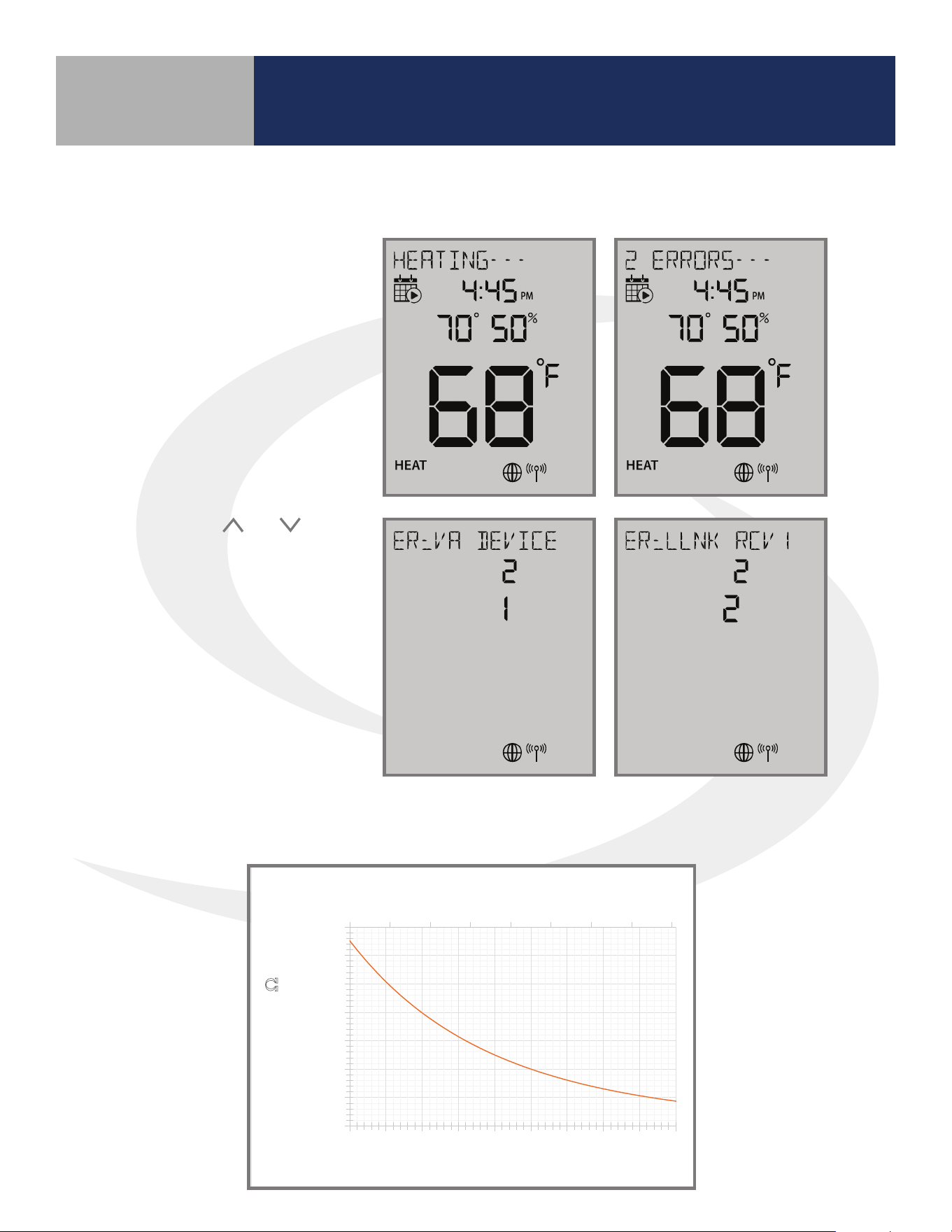
Error messages are displayed on the alphanumeric text line at the top of the screen. These
messages will alternate with the current status message.
Table 10.1 – Error Messages
48
AWRT10RF Wireless Radiant Thermostat -
Troubleshooting
Section 10.0
If there is more than one
error, the AWRT10RF
Thermostat will show the
number of errors on the text
message line alternating
with the standard display.
Pressing the
and
keys while the “# ERRORS”
message is displayed allows
review of all errors. The
lower number indicates the
error sequence .
External Sensor Resistance vs. Temperature
10.2 – Reading Multiple Error Messages
Figure 10.3 – Optional External Sensor Resistance Graph
32 42 52 62 72 82 92 102 112
-
5,000
10,000
15,000
20,000
25,000
30,000
35,000
0 5 10 15 20 25 30 35 40 45
Temperature (⁰F)
Resistance (Ω)
Temperature (⁰C)
49
AWRT10RF Wireless Radiant Thermostat 08/2018
SUBMITTAL
Job or Customer:
Location:
Engineer:
Contractor:
SALUS Rep:
Submitted by:
Date:
Approved by:
Date:
The AWRT10RF Wireless Radiant Thermostat communicates wirelessly with the SALUS Wireless System to maintain
the space temperature. This thermostat will can be set up for AKL01/04/06PRF or AKL08RF Wiring Centers,
ARV10RFM Radiator Valve Actuators or AX10RF Receivers. The battery operated AWRT Thermostat can monitor and
maintain temperatures, create setpoint schedule programs and other user interface functions.
Features:
Specifications:
- Built-in wireless communication
support
- Operates as standalone wireless or
web connected system
- Manual or automatic Heating/Cooling
changeover
- 1 ½ year expected battery life
- 6-button touch keypad
- Heating zone setup via thermostat or
web application:
• Operating mode
• 7-day schedule, 6 periods per day
• Automatic freeze protection
- Occupancy display
- Keylock directly or by web application
- Mountable on home or office walls
Model:
AWRT10RF Wireless Radiant Thermostat
Package
Dimensions:
Length
Width
Height
Package
Weight:
6.18”
2.68”
1.38”
0.50 Lbs
15.7 cm
6.8 cm
3.5 cm
225 g
Enclosure
Material:
White PC/ABS Plastic
Approvals:
Meets Class B ICES & FCC Part 15
Operating Temp:
Indoor use only, 32 to 122F (0 to 50C), RH <90% non-
condensing
Storage Temp:
14 to 140F (-10 to 60C)
Power Supply:
2 x AA Batteries
Temperature
Sensor:
Internal thermistor, 10 k @ 77F (25C ± 0.2C)
Measurement Range: 32 - 99F (0 - 40C)
Resolution: 1F (0.5C)
User Interface:
Set point range:
Heating: 41 - 92F (5 – 33.5C)
Cooling: 44 - 95F (6.5 - 35C)
Controls:
SELECT
Indications:
Temperature, Day of the Week, Heat/Cool,
Settings, Key Lock
Backlit fixed segment LCD Display
User settings stored in non-volatile memory
AWRT10RF Wireless Radiant Thermostat -
Specifications
Section 11.0
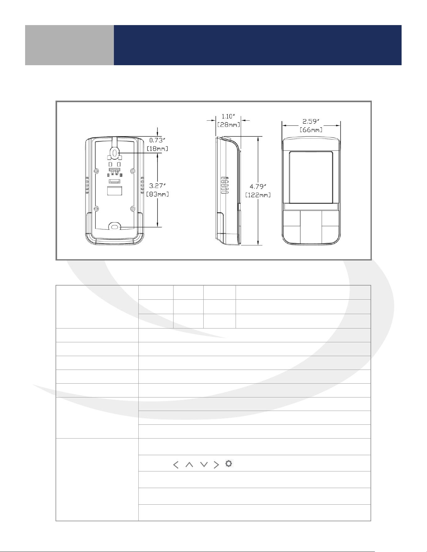
Package Dimensions
Length Width Height Weight
6.18” 2.68” 1.38”
0.5 Lbs
15.7 cm 6.8 cm 3.5 cm
225 g
Enclosure Material White PC/ABS Plastic
Approvals Meets Class B ICES & FCC Part 15
Operating Temperature Indoor use only, 32 to 122°F (0 to 50°C), RH <90% noncondensing
Storage Temperature 14 to 140
º
F (-10 to 60°C)
Power Supply 2 x AA Batteries
Temperature Sensor
Internal thermistors, 10 kΩ @ 77
º
F (25
º
C ± 0.2
º
C)
Measurement Range: 32 - 99
º
F (0 - 40
º
C)
Resolution: 1
º
F (0.5
º
C)
User Interface
Set Point Range: Heating: 41 - 92
º
F (5 – 33.5
º
C) / Cooling: 44 - 95
º
F (6.5 - 35
º
C)
Controls:
SELECT
Indications: Temperature, Day of the Week, Heat/Cool, Settings, Key Lock
Backlit xed segment LCD Display
User settings stored in non-volatile memory
Thermostat Dimensions
Specications

50
Installer Notes
Section 12.0