INSTALLER / USER MANUAL
Wireless Receiver Unit
Models: AX10RF
www.salusna.com
SALUS North America
850 Main Street
Redwood City
CA 94063
T: +1-650-360-1725
For PDF Installation guide please go to
www.salusna.com
Maintaining a policy of continuous product development SALUS
Controls plc reserve the right to change specication, design and
materials of products listed in this brochure without prior notice.
SALUS North America is a member of the Computime Group
00086/2 Issue Date: Oct 2016
SALUS North America warrants that this product will be free from any defect in materials or
workmanship, and shall perform in accordance with its specication, for a period of ve years from
the date of installation. SALUS North America sole liability for breach of this warranty will be (at its
option) to repair or replace the defective product.
Customer Name: ..........................................................................................................
Customer Address: .......................................................................................................
................................................................ Post Code: ...................................................
Tel No: .................................................... Email: ..........................................................
Engineers Company: ....................................................................................................
Tel No: .................................................... Email: ..........................................................
Instalation Date: ..........................................................................................................
Engineers Name: .........................................................................................................
Engineers Signature: ...................................................................................................
WARRANTYTECHNICAL DETAIL
INSTALLATION
Model AX10RF
Type Wired system receiver designed for 24VAC
heating applications
Control ON-OFF control
Environment Ratings
Operating Temperature 0 ºC to +50 ºC
Storage Temperature -20 ºC to +60 ºC
Operating Humidity 5-95 %RH
Switch Voltage 0-24VAC 16AMP
Power Source 24 VAC 60Hz
User Interface Slide switch, LED, RED/GREEN
Operating Temperature 0 to 50 ºC
Storage Temperature -20ºC to 60ºC
Frequency 2.45 GHz
Approval FCC and IC
Terminal Function
COM Common Contact (volt free input)
NO Normally Open Contact (volt free output)
Earth Parking
H Incoming Mains - Live
N Incoming Mains - Neutral
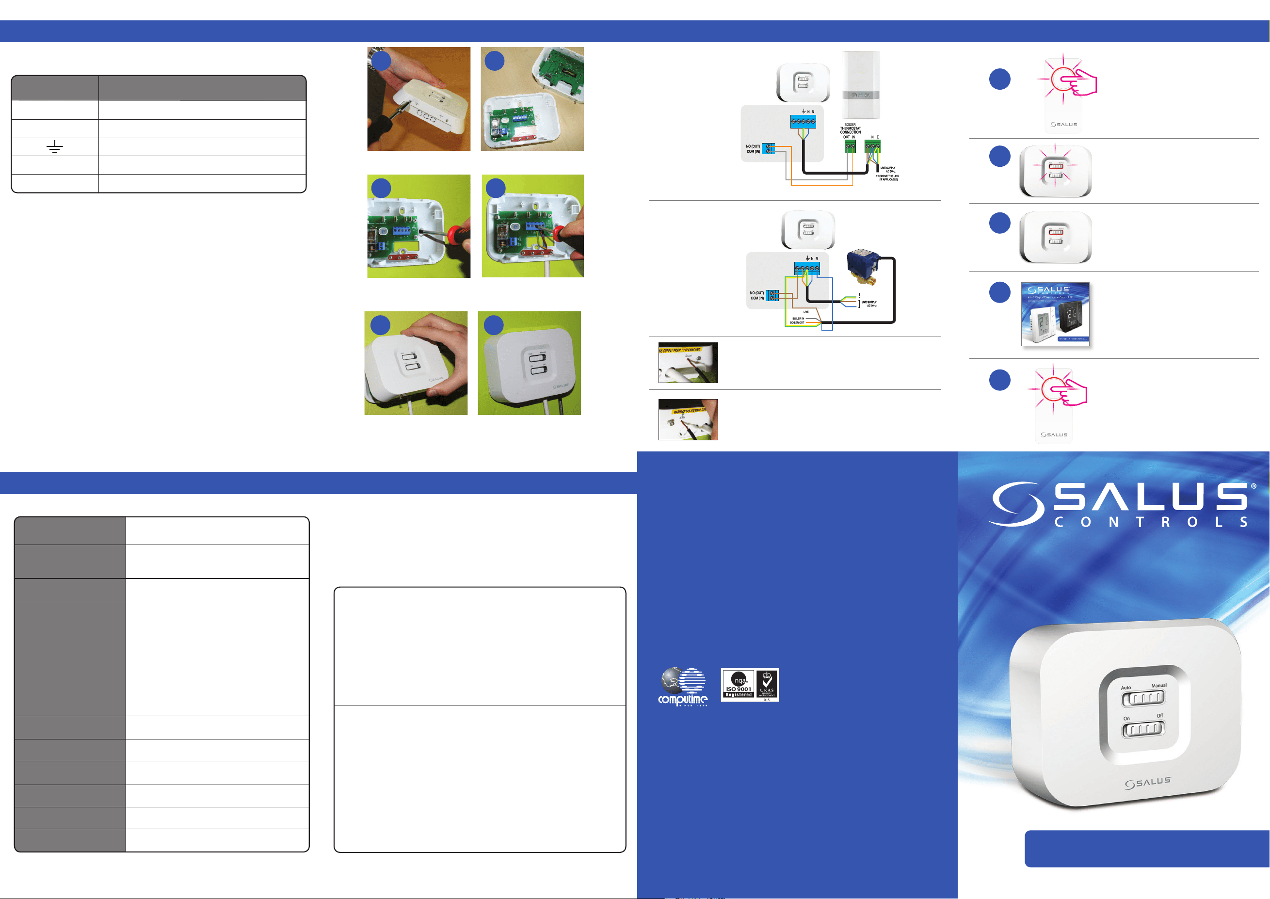
Clip the front of the unit back on by aligning the
ttings and pushing into place.
Securely screw the front of the receiver in place.
Wire up the receiver using
one of the schematics*.
4
5
1
2
3
4
5
6
Loosen the screws at the bottom of the receiver unit. Unclip the front of the unit.
Fit the back of the receiver unit to the wall
using the ttings supplied.
1 2
3
Ensure Coordinator is powered
up and ready for pairing.
Power up the receiver.
The red light will ash.
When the receiver has successfully
joined the Zigbee network, the red
LED will go steady.
Please refer to AS20RF
manual for system pairing.
Once your system setup is complete,
remember to take the coordinator
out of pairing mode.
Reset Button
If for any reason the system receiver stops operating, press
reset and check system operation.
*Congured
as RX2
*Congured
as RX1
Replacing the System Receiver
If for any reason the system receiver needs to be removed/
replaced, press the delete from network.
Electrical Connection Schematics Power Up
The AX10RF Receiver should be mounted in a suitable location that is both accessible
for the connection of mains and control wiring, and allows good reception of the RF
signal. The Receiver needs a 24 VAC mains supply to operate, and this should be fused
appropriately (16A max.).
The Receiver should be mounted in a location where it will not come into contact
with water, moisture or condensation. There are few electrical connections required
to the AX10RF, and these connections should be made to the terminal block inside
the Receiver. No Earth connection is required for the correct and safe operation of the
AX10RF, but a parking terminal is provided to connect an Earth wire if one is present.
JG Boiler Receiver Reduced.qxp_Layout 1 24/11/2014 10:17 Page 4
JG Boiler Receiver Reduced.qxp_Layout 1 24/11/2014 10:17 Page 4
JG Boiler Receiver Reduced.qxp_Layout 1 24/11/2014 10:17 Page 4
H H
H
JG Boiler Receiver Reduced.qxp_Layout 1 24/11/2014 10:17 Page 4
H H
24V
24V
BOX CONTENTS, COMPLIANCE & SAFETY INFORMATION
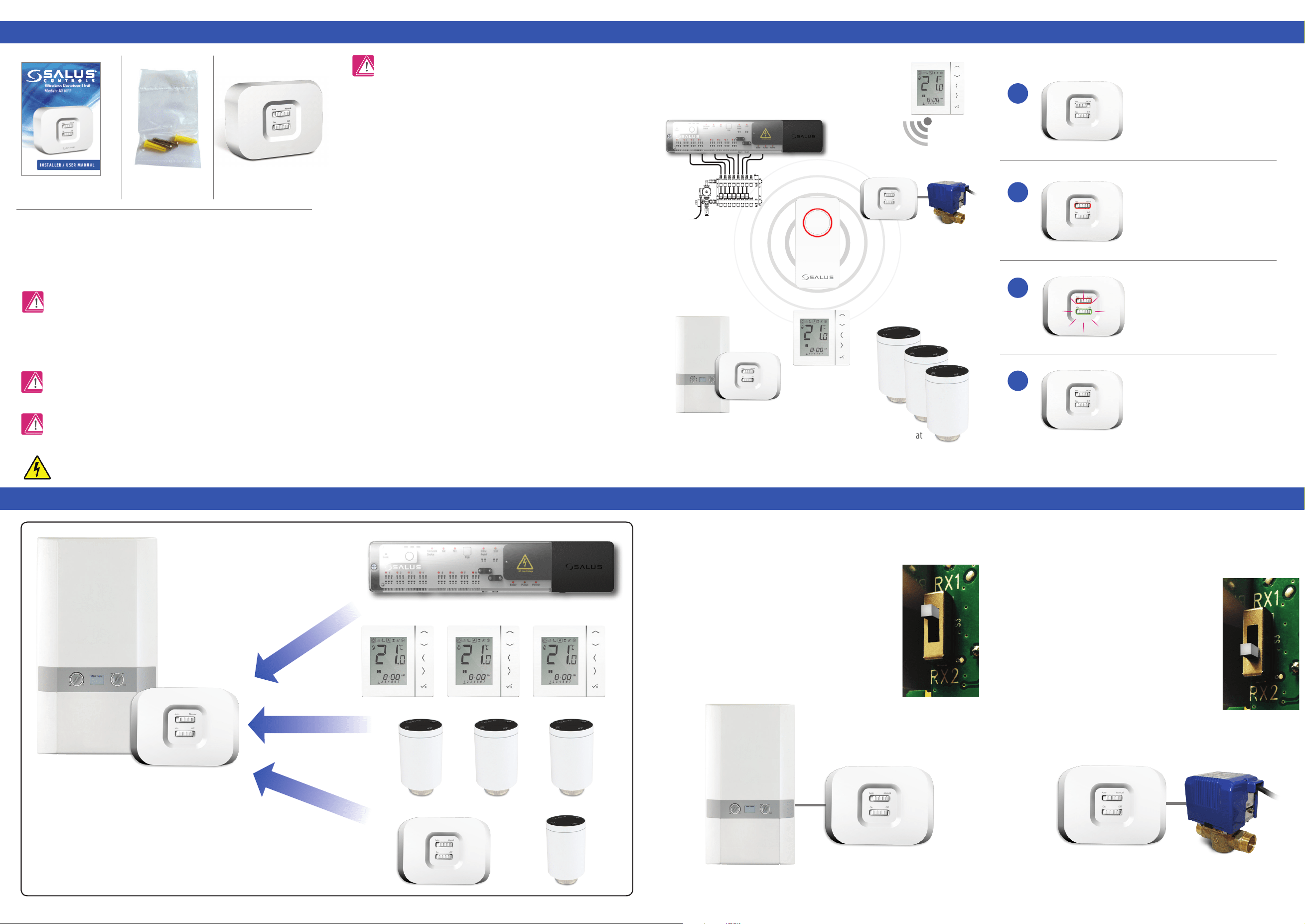
SYSTEM OVERVIEW - WYSE.LY SYSTEM CONFIGURED AS RX1 SYSTEM OVERVIEW - WYSE.LY SYSTEM CONFIGURED AS RX2
SYSTEM OVERVIEW
1 x Installer / User manual
Boiler Receiver x 1
2 x Screws
& 2 x Wall Plugs
24 V AC
Sources of danger
The AX10RF must be disconnected from mains supply before removing the cover.
Emergency
Switch o the voltage to the individual thermostat wring centre or complete system.
Warning
This product must be tted by a competent person, and installation must comply with the guidance,
standards and regulations applicable to the city, country or state where the product is installed. Failure to
comply with the requirements of the relevant guidance, standards and regulations could lead to injury, death
or prosecution.
Warning
Always isolate the AC Mains supply before installing or working on any components that
require 24 VAC 60Hz supply.
INTRODUCTION
Thank you for purchasing the SALUS AX10RF system receiver. This unit is designed to work with Wyse.ly range
of Zigbee network products.
The AX10RF can be congured as remote boiler switch or a simple single channel output to control, a thermal
actuator or zone valve. Please note the two conguratons above can be used together in the one system.
These instructions are applicable to the SALUS model stated on the front cover of this manual only.
FCC Statement
This equipment has been tested and found to comply with the limits for a Class B digital device, pursuant
to Part 15 of the FCC Rules. These limits are designed to provide reasonable protection against harmful
interference in a residential installation. This equipment generates uses and can radiate radio frequency
energy and, if not installed and used in accordance with the instructions, may cause harmful interference
to radio communications. However, there is no guarantee that interference will not occur in a particular
installation. If this equipment does cause harmful interference to radio or television reception, which can be
determined by turning the equipment o and on, the user is encouraged to try to correct the interference by
one or more of the following measures:
• Reorient or relocate the receiving antenna.
• Increase the separation between the equipment and receiver.
• Connect the equipment into an outlet on a circuit dierent from that to which the receiver is connected.
• Consult the dealer or an experienced radio/TV technician for help.
Changes or modications not expressly approved by the party responsible for compliance could void the
user’s authority to operate the equipment.
This device complies with part 15 of the FCC Rules. Operation is subject to the following two conditions: (1)
This device may not cause harmful interference, and (2) this device must accept any interference received,
including interference that may cause undesired operation.
This device complies with Industry Canada’s licence-exempt RSSs. Operation is subject to the following two
conditions:
(1) This device may not cause interference; and
(2) This device must accept any interference, including interference that may cause undesired operation
of the device.
Le présent appareil est conforme aux CNR d’Industrie Canada applicables aux appareils radio exempts de
licence. L’exploitation est autorisée aux deux conditions suivantes : (1) l’appareil ne doit pas produire de
brouillage, et (2) l’utilisateur de l’appareil doit accepter tout brouillage radioélectrique subi, même si le
brouillage est susceptible d’en compromettre le fonctionnement.
The unit can be switched internally switched to be used on two channels, RX1
(boiler receiver) or RX2 (single room receiver). Ensure the unit is not powered
during setting of the RX1/RX2 slide switch.
The unit is supplied with the switch in the RX1 position (Boiler
Receiver). In this mode, the unit can be wired to the boiler to
switch it on or o using the wireless signals it receives other
SALUS products on the SALUS Zigbee network
With the unit switched to RX2, the unit will act as a single room receiver. Switching
of the unit will be controlled by a paired SALUS AS20RF Thermostat. Depending on
its intended use, the unit can be used to switch a motorised valve, thermal actuator
or pump.
As well as being used in this way, the RX2 can be used
in conjunction with another unit set up as an RX1 (Boiler
receiver). When there is a call for heat from the thermostat
paired to the RX2 both of the wireless receivers will operate
turning on both the boiler and the motorised valve / pump.
NB: Only 1 RX1 and 1 RX2 can be used as part of a network.
*System Receiver congured
to boiler receiver. RX1
AX10RF congured
as Boiler Receiver RX1.
**System Receiver congured
to one room receiver RX2.
RX1
Max 6 ARV per thermostat
UNDERFLOOR HEATING MANIFOLD
System Receiver congured to boiler receiver RX1.
Refer to reverse side for wiring.
System receiver congured as stand alone receiver
RX2. Refer to reverse side for wiring.
RX1 & RX2 RECEIVER CONFIGURATION
The receiver can be congured as a Boiler Receiver (RX1) where
it will react to signals from a large number of components such
as SALUS wireless wiring centres, wireless thermostats used
with SALUS wireless radiator valves as well as another receiver
congured as a Stand Alone receiver (RX2).
1
2
3
4
User InterfaceWyse.ly System
AUTO – System receiver output
will switch on and off in relation
to the command from the Wise.ly
transmitter. The bottom slide switch
in active
RED led only in AUTO means that there
is no output from the receiver.
RED and Green LED only in AUTO
means that there is an output from the
receiver. The device that the receiver is
connected to will be switched on.
Manual- system receiver output is
controlled by the bottom slide switch.
Either permenetly ON or OFF. The LED
status in manual is the same as AUTO.
AS20RF
AX10RF*
AC10RF
AX10RF**
VS10/20RF
AKL08RF