Store this manual for future reference
8500-110-02
®
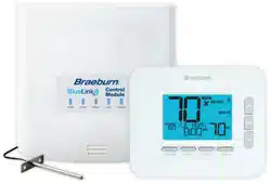
Universal Programmable
Wireless Thermostat Kit
User Manual
Read all instructions before proceeding.
Up to 3 Heat / 2 Cool Heat Pump
Up to 2 Heat / 2 Cool Conventional
8500
This manual covers the following thermostat model:
See Wireless Setup Guide for Wireless Setup Instructions

Contents
1
About Your Thermostat
Quick Reference - Thermostat .................................. 4
Quick Reference - Control Module ............................8
2
User Settings
Accessing User Settings ........................................... 9
Table of User Settings .............................................10
Resetting Service Reminders ..................................10
Setting the Time and Day ........................................11
Service Reminders ..................................................12
Temperature & Lock Code .......................................13
Resetting Thermostat ..............................................14
3
Setting Your Program Schedule
Tips Before Setting Your Program Schedule .............15
Default Energy Saving Programs..............................16
Programming a 7 Day Schedule ..............................17
Programming a 5-2 Day Schedule ...........................19
4
Operating Your Thermostat
Setting the System Control Mode .........................20
Setting the Fan Control Mode ...............................21
Temperature Adjustment ......................................22
Program Event Indicators .....................................23
System Status and Maintenance Indicators ..........24
Communication Loss ........................................... 25
Remote Sensor - Low Batteries ........................... 29
5
Additional Operation Features
Auto Changeover Mode ....................................... 30
Adaptive Recovery Mode ..................................... 30
Circulating Fan Mode ...........................................31
Programmable Fan Mode .....................................31
Compressor Protection .........................................31
Locking and Unlocking the Thermostat ................ 32
Outdoor Remote Sensing ..................................... 33
Indoor Remote Sensing ........................................ 33
6
Thermostat Maintenance
Battery Replacement ........................................... 34
Thermostat Cleaning ........................................... 34
User Manual 2

Congratulations! You are in control of one of the easiest-to-use thermostats on the market today.
This thermostat has been designed to provide you with years of reliable performance and comfort control.
Features
• Reliable BlueLink
®
Wireless Technology
• Stylish new design with large display and bright blue backlight
• SpeedSet
®
programming gives you the option of programming all 7 days at once
• Convenient HOLD feature lets you override the program schedule
• Extra large display characters make viewing settings even easier
• User selectable service monitors remind you of required system maintenance
• Multi-level keypad lockout prevents unauthorized use
• Precise temperature accuracy keeps you in control of your comfort
• Convenient programmable and circulating fan modes
• Optional indoor or outdoor remote sensing (wired or wireless)
• Expanded commercial features (commercial configuration only)
3 User Manual
1
About Your Thermostat
User Manual 4
1
5
2 3 4
6
7

5 User Manual
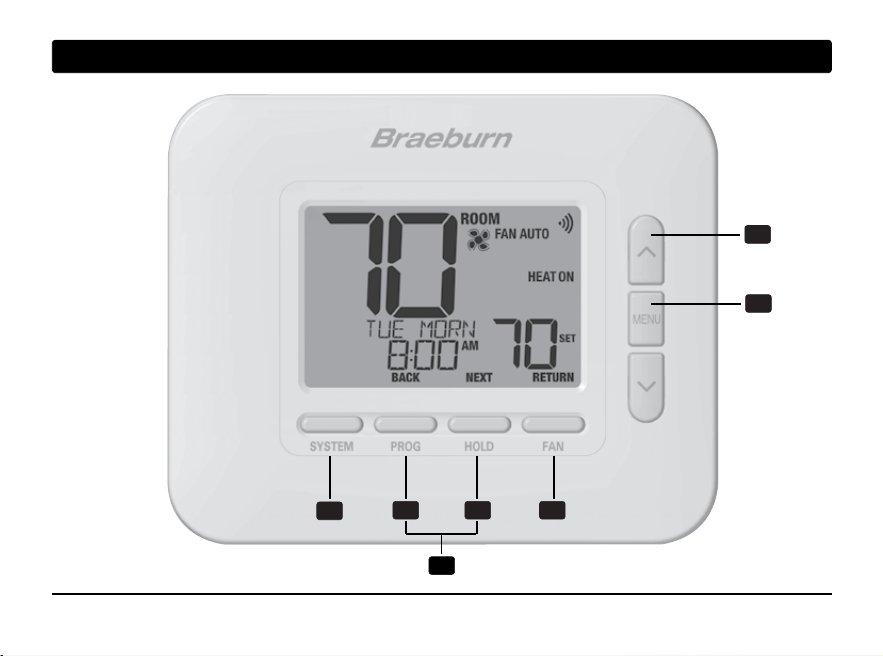
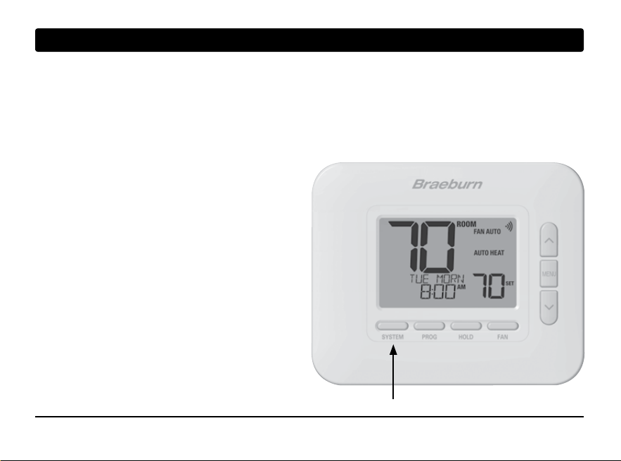
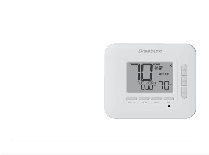
SYSTEM Button .................... Selects the system you want to control
PROG Button .........................Enters programming mode or hold for 3 seconds to enter SpeedSet
®
mode
BACK Button* ........................ Secondary function of the PROG button - Moves to previous setting
HOLD Button ......................... Enters / Exits HOLD mode (program bypass mode)
NEXT Button* ........................ Secondary function of the HOLD button - Moves to next setting
FAN Button ............................ Selects the system fan mode
RETURN Button* .................... Secondary function of the FAN button - Exits program or settings modes
Up / Down Arrow Buttons ..... Increases or decreases settings (time, temperature, etc.)
MENU Button ......................... Used to access user settings mode
Lock / Unlock Thermostat .... Access user Lock / Unlock screen by holding PROG and HOLD
together for 5 seconds
Battery Compartment .......... Located on the back side of thermostat (if installed)
1
2
3
4
5
6
7
Thermostat
* BACK, NEXT and RETURN are secondary functions of the PROG, HOLD and FAN buttons. When in programming
or configuration modes, BACK, NEXT and RETURN appear in the display screen indicating that the PROG, HOLD
and FAN buttons now function as BACK, NEXT and RETURN.
1
About Your Thermostat
1
3
2
7
4
8
9
6
5
12
11
User Manual 6
10

7 User Manual
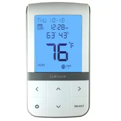
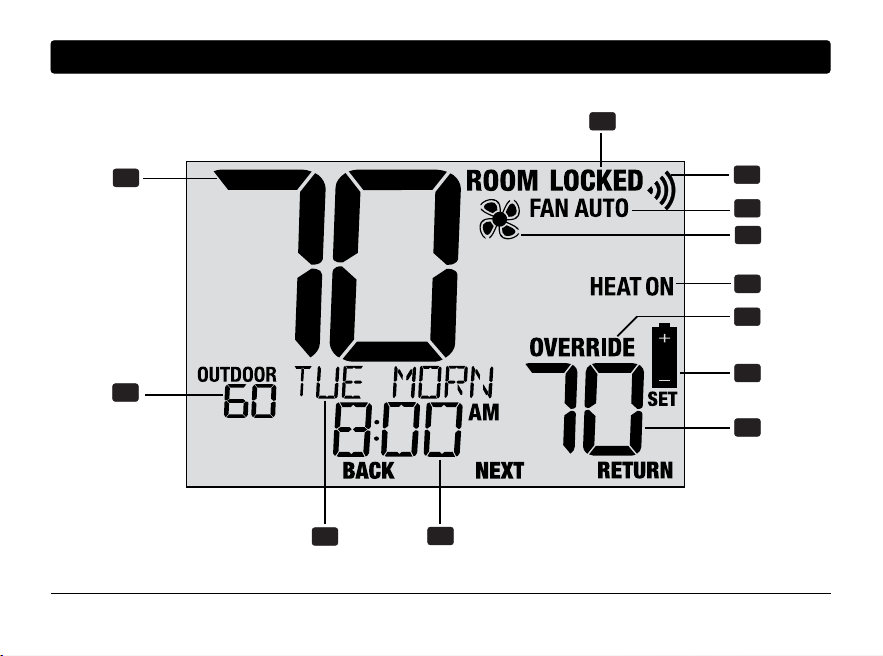
Room Temperature .............................Displays the current room temperature
Set Temperature .................................Displays the current setpoint temperature
Outdoor Temperature .......................... If a Braeburn
®
outdoor sensor is connected, the
outdoor temperature will be displayed
Override Indicator ................................ Indicates that the current program schedule has
been temporarily overridden
Time of Day .......................................... Displays the current time of day
Message Center ................................... Displays various thermostat status and
maintenance information
System Mode ...................................... Displays the system mode and current system status
Fan Mode Indicator .............................. Indicates the current system fan mode
Fan Status Indicator ............................ Indicates that the system fan is running
Lock Mode Indicator ............................ Indicates if the thermostat is locked
Low Battery Indicator .......................... Indicates when the batteries need to be replaced
Wireless Indicator ................................ Indicates the status of the wireless connection
Thermostat Display
1
2
3
4
5
6
7
8
9
10
11
12
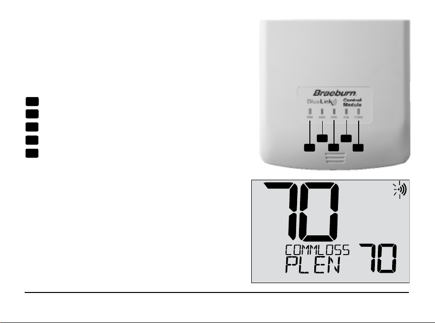
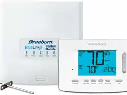
Control Module
Your thermostat communicates wirelessly with a control
module installed on or near your heating/cooling equipment.
This control module is wired directly to your equipment.
User Manual 8
1
2
3
4
5
NOTE: There is a return air sensor connected to the control
module to maintain default temperature control should the
batteries ever become drained in the thermostat. If the return
air plenum sensor becomes disconnected, the thermostat
will display the words COMMLOSS PLEN SENS. If you see this
message, contact a local service technician.
PWR: 24 VAC Power Indicator
HEAT: HEAT ON Indicator
COOL: COOL ON Indicator
FAN: FAN ON Indicator
COMM: Communication Indicator
1
2
3
4
5
Control Module LED Indicators
2
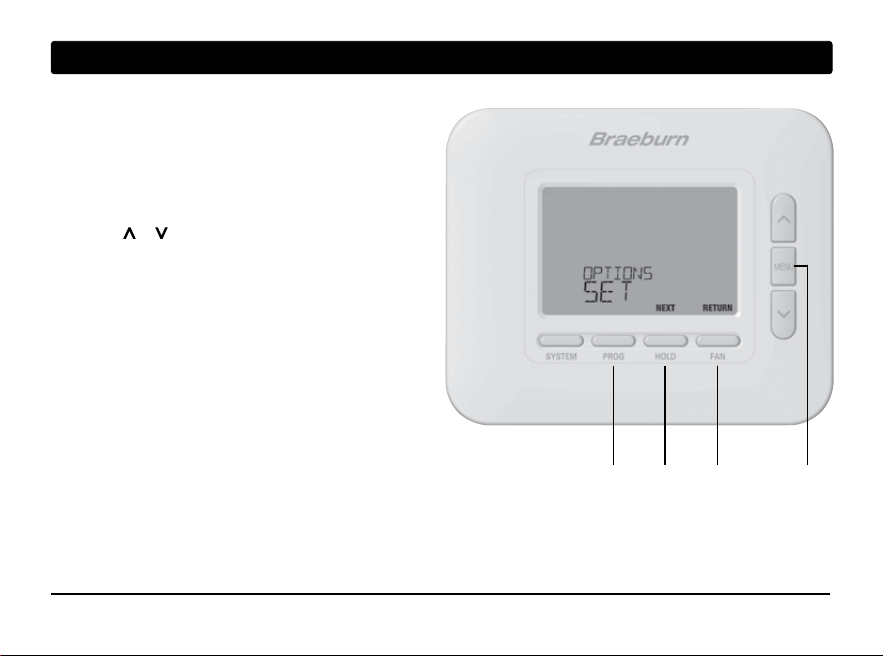
User Settings
User Settings allow you set the current time of day as
well as customize various thermostat features.
To Enter User Settings Menu
1. Press and release the MENU button
2. Use the or buttons to select OPTIONS SET
3. Press NEXT (HOLD) to confirm this choice and
enter the User Settings Menu
To Navigate the User Settings Menu
4. Press NEXT (HOLD) or BACK (PROG) to move
to the next or previous setting
5. Press RETURN (FAN) to exit or wait 30 seconds
MENU
9 User Manual
BACK NEXT
RETURN
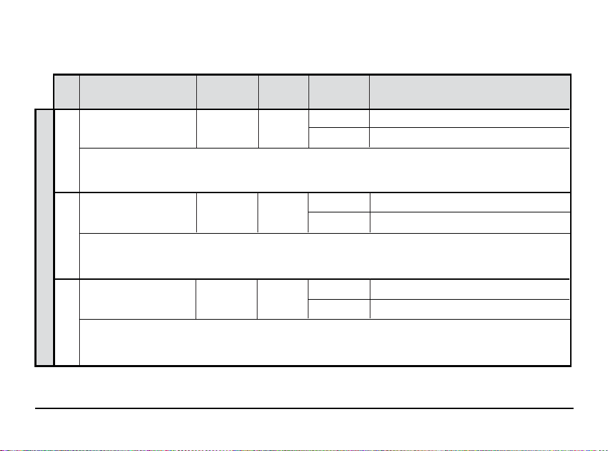
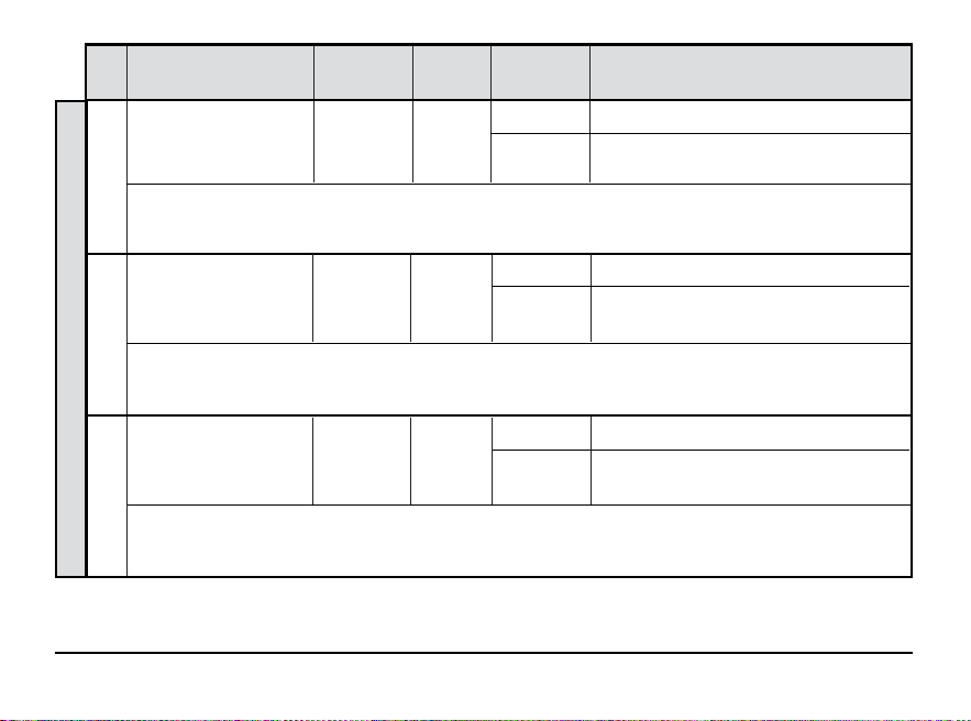
Table of User Settings
NOTE: Some user settings may not be available, depending on how the thermostat was configured during installation.
No.
User Setting
Displayed
Default
Available
Description of
Setting Settings Available Settings
1 Reset FILTER RESET / N0
FILTER
[Only appears if the service filter time interval has expired] If a service filter time interval was selected in setting 7,
the thermostat will display a SERVICE FILTER message once that time interval is reached. Select NO to keep the message
displayed or select YES to clear the message and reset the timer.
2 Reset UV BULB
RESET / NO
UV BULB
[Only appears if the service UV bulb time interval has expired] If a service UV bulb time interval was selected in
setting 8, the thermostat will display a SERVICE UV BULB message once that time interval is reached. Select NO to keep
the message displayed or select YES to clear the message and reset the timer.
3 Reset HUMID PAD
RESET NO
HUM PAD
[Only appears if the humidifier pad service time interval has expired] If a service humidifier pad time interval was
selected in setting 13, the thermostat will display a SERVICE HUM PAD message once that time interval is reached.
Select NO to keep the message displayed or select YES to clear the message and reset the timer.
N0 Select to keep message displayed
YES Select to remove message and reset timer
NO Select to keep message displayed
YES Select to remove message and reset timer
NO Select to keep message displayed
YES Select to remove message and reset timer
Conditional Service Reminders
User Manual 10
No.
User Setting
Displayed
Default
Available
Description of
Setting Settings Available Settings
1 Reset FILTER RESET / N0
FILTER
[Only appears if the service filter time interval has expired] If a service filter time interval was selected in setting 7,
the thermostat will display a SERVICE FILTER message once that time interval is reached. Select NO to keep the message
displayed or select YES to clear the message and reset the timer.
2 Reset UV BULB
RESET / NO
UV BULB
[Only appears if the service UV bulb time interval has expired] If a service UV bulb time interval was selected in
setting 8, the thermostat will display a SERVICE UV BULB message once that time interval is reached. Select NO to keep
the message displayed or select YES to clear the message and reset the timer.
3 Reset HUMID PAD
RESET NO
HUM PAD
[Only appears if the humidifier pad service time interval has expired] If a service humidifier pad time interval was
selected in setting 13, the thermostat will display a SERVICE HUM PAD message once that time interval is reached.
Select NO to keep the message displayed or select YES to clear the message and reset the timer.
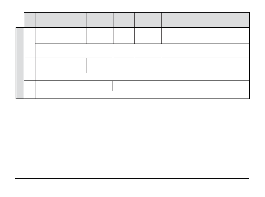
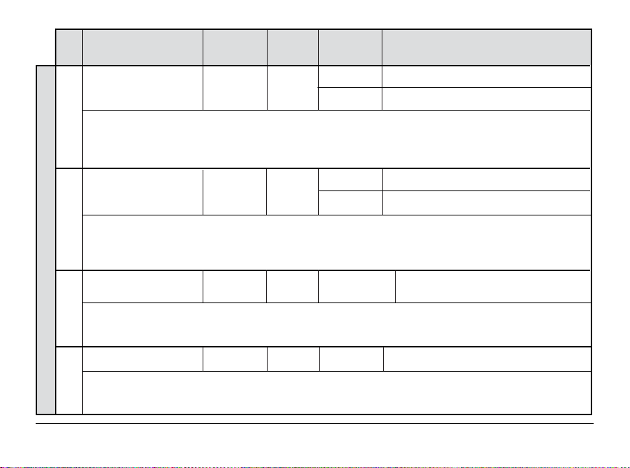
No.
User Setting
Displayed
Default
Available
Description of
Setting Settings Available Settings
4 Current Time of Day SET TIME 12:00
(Hour)
Set the current hour of the day. If thermostat was configured for a 24-hour clock, the settings 0-24 will be available.
If the thermostat was configured for a 12-hour clock, this is also how you will select between a.m. and p.m.
5 Current Time of Day
SET TIME 12:00
(Minute)
Set the current minute of the hour.
6 Current Day of Week
SET DAY MON
Set the current day of the week.
1-12 Select the current hour of day
00-60 Select the current minute of the hour
MON-SUN Select the current day of the week
Time and Day
11 User Manual
No.
User Setting
Displayed
Default
Available
Description of
Setting Settings Available Settings
7 Service Filter Timer
FILTER OFF
Select the number of days before receiving a reminder to change your system filter (if applicable). When the filter interval
timer interval has expired, the thermostat will display the message SERVICE FILTER. To reset this reminder, see setting
1. To disable, select OFF.
8 Service UV Bulb Timer
UV BULB OFF
‘ Select the number of days before receiving a reminder to change your system UV bulb (if
applicable
). When the
timer interval has expired, the thermostat will display the message SERVICE UV BULB. To reset this reminder, see
setting 2. To disable, select OFF.
9 Ser vice Humidifier
HUM PAD OFF
Pad Timer
Select the number of days before receiving a reminder to change your humidifier pad (if applicable). When the timer
interval has expired, the thermostat will display the message SERVICE HUM PAD. To reset this reminder, see setting 3.
To disable, select OFF.
Service Reminders
OFF Service filter timer is disabled
30, 60, 90,
Select number of days for service filter timer
120, 180, 365
OFF Service UV bulb timer is disabled
180, 365
Select number of days for service
UV bulb timer
OFF Service humidifier pad timer is disabled
180, 365
Select number of days for service
humidifier pad timer
User Manual 12
No.
User Setting
Displayed
Default
Available
Description of
Setting Settings Available Settings
10 Temperature Hold Time
HOLD LONG
(HOLD Button)
[Only available if programming is enabled] Temperature Hold Time lets you select the time that your thermostat will
hold the temperature when the HOLD button has been pressed. When LONG is selected, the thermostat will hold your
temperature indefinitely. When 24HR is selected, the thermostat will hold your temperature for 24 hours and then return
to the current program temperature.
11 Temperature Override
ADJ LIMIT OFF
Adjustment Limit
‘
The Temporary Override Adjustment Limit will limit how much the temperature can be adjusted from the current setpoint
program temperature. If thermostat is set to non-programmable mode, this setting only applies when the thermostat is
locked and will not allow the user to override the temperature past the selected limit amount of 1, 2 or 3 degrees from
the current setpoin
t.
12 Program Override
OVERRIDE 4 HOUR
Time Limit
[Only available if programming is enabled] The Program Override Time Limit allows you to set a maximum time limit
(in hours) that the thermostat will return to the program after a temporary temperature override has been made. You
may select 1, 2, 3 or 4 hours.
13 Thermostat Lock Code
SET LOCK 000
The Thermostat Lock Code sets a 3-digit code that you may use at any time to lock or unlock the thermostat keypad.
Setting the 3-digit code does not activate the lock feature. To lock or unlock the thermostat, see Locking/Unlocking
Thermostat, section 5. The lock code 000 cannot be used.
Temperature and Lock Code
LONG Select for long (permanent) HOLD mode
24HR
Select for 24 hour (temporary) HOLD mode
OFF Disables adjustment limit
1, 2, 3
Select adjustment limit of 1°, 2° or 3°
4 HOUR, 3 HOUR
Select a program override time limit
2 HOUR, 1 HOUR
of 1-4 hours
0-9
Select a 3-digit lock code of 0-9 for each digit
13 User Manual
No.
User Setting
Displayed
Default
Available
Description of
Setting Settings Available Settings
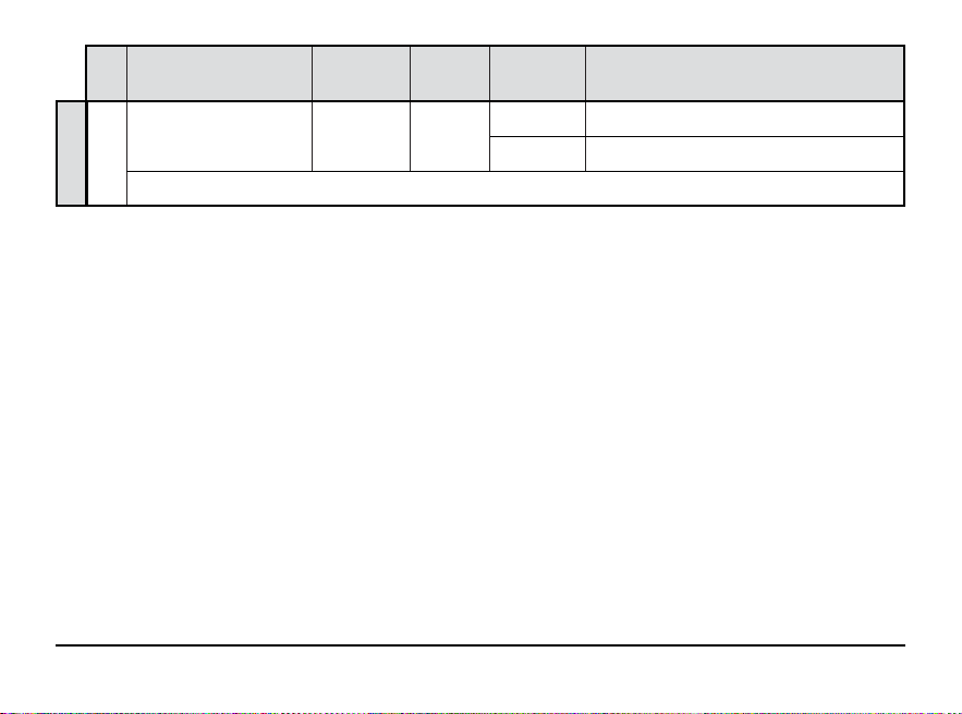
14 User Reset RESET NO
Selecting YES will reset all user settings, program and current time. Thermostat lock code and Installer Settings will not be affected.
NO Reset disabled - no changes made
YES
Reset enabled - resets thermostat
RESET
User Manual 14
NOTE: This reset will not affect the lock code, wireless connection of the thermostat and/or any connected
remote sensors. If you wish to reset the wireless connection, please refer to the wireless setup guide.
No.
User Setting
Displayed
Default
Available
Description of
Setting Settings Available Settings
14 User Reset RESET NO
Selecting YES will reset all user settings, program and current time. Thermostat lock code and Installer Settings will not be affected.
15 User Manual
3
Setting Your Program Schedule
Tips Before Setting Your Program Schedule
• Make sure your current time and day of the week
are set correctly.
• Make sure the AM and PM indicators are correct.
• Various installer settings such as auto changeover mode
and temperature adjustment limits may affect your
programming flexibility.
• Your NITE event cannot exceed 11:50 p.m.
• BACK, NEXT and RETURN are secondary functions of the
PROG, HOLD and FAN buttons.
This thermostat has been configured with one of
the following programming options:
• Residential 7-day programming mode with 4 events per day
• Residential 5-2 (weekday/weekend) programming mode
with 4 events per day
• Commercial 7-day programming mode with 2 events per day
• Non-Programmable mode
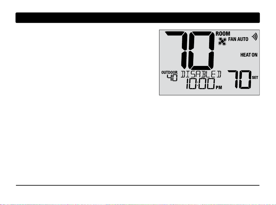
NOTE: If this thermostat was configured to be
non-programmable, then you cannot set a program
schedule. If you press the PROG or HOLD buttons,
the word “DISABLED” will appear in the display.

Default Energy Saving Programs
This thermostat comes pre-programmed with a default energy saving program. The following tables outline
the pre-programmed times and temperatures for heating and cooling in each of your 4 daily events (2 events if
configured for commercial mode). If you wish to use these settings, then no further programming is necessary:
MORN
DAY
EVE
NITE
Time: 6:00 pm
Heat: 70˚ F (21˚ C)
Cool: 78˚ F (26˚ C)
Time: 8:00 am
Heat: 62˚ F (17˚ C)
Cool: 85˚ F (29˚ C)
Time: 6:00 am
Heat: 70˚ F (21˚ C)
Cool: 78˚ F (26˚ C)
Time: 10:00 pm
Heat: 62˚ F (17˚ C)
Cool: 82˚ F (28˚ C)
4 Event
All Days
Residential 7 Day Programming
Factory Settings
Weekday Weekend
Time: 6:00 pm
Heat: 70˚ F (21˚ C)
Cool: 78˚ F (26˚ C)
Time: 8:00 am
Heat: 62˚ F (17˚ C)
Cool: 85˚ F (29˚ C)
Time: 6:00 am
Heat: 70˚ F (21˚ C)
Cool: 78˚ F (26˚ C)
Time: 10:00 pm
Heat: 62˚ F (17˚ C)
Cool: 82˚ F (28˚ C)
Time: 6:00 pm
Heat: 70˚ F (21˚ C)
Cool: 78˚ F (26˚ C)
Time: 8:00 am
Heat: 62˚ F (17˚ C)
Cool: 85˚ F (29˚ C)
Time: 6:00 am
Heat: 70˚ F (21˚ C)
Cool: 78˚ F (26˚ C)
Time: 10:00 pm
Heat: 62˚ F (17˚ C)
Cool: 82˚ F (28˚ C)
5-2 Day Programming
Weekday/Weekend Factory Settings
Time: 8:00 am
Heat: 70˚ F (21˚ C)
Cool: 78˚ F (26˚ C)
OCC
UNOC
Time: 6:00 pm
Heat: 62˚ F (17˚ C)
Cool: 85˚ F (29˚ C)
2 Event
All Days
Commercial 2 Event Programming
Factory Settings
User Manual 16
17 User Manual
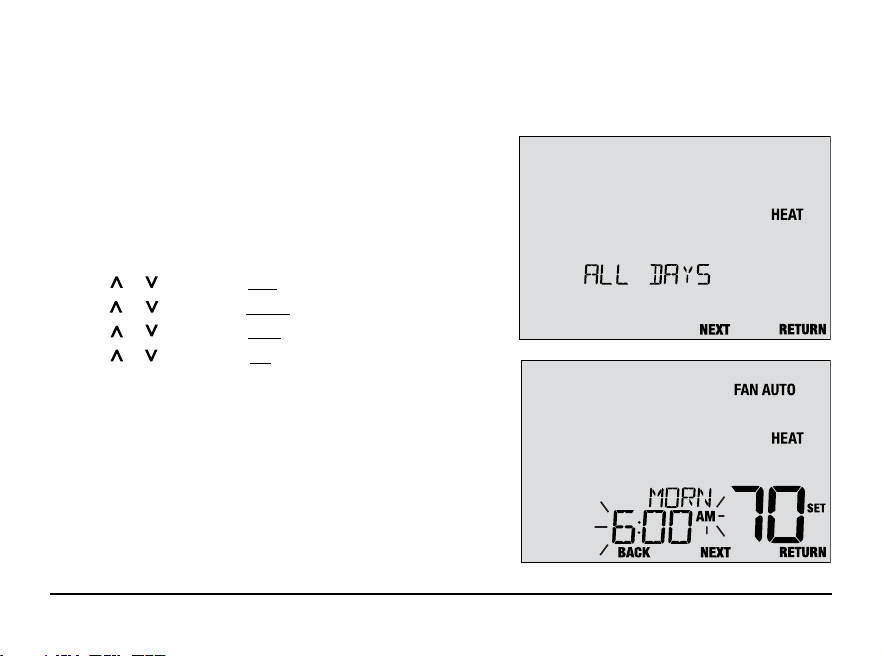
Setting a 7-Day program – All 7 Days at Once (SpeedSet
®
)
(7-day residential or commercial programming mode only)
NOTE: Setting all 7 days at once will copy over any previously programmed individual days.
Available Daily Events
Residential mode: MORN, DAY, EVE, NITE
Commercial mode: OCC, UNOC
1.
Hold the PROG button for 3 seconds until ALL DAYS appears.
2. Press SYSTEM to select HEAT or COOL. Press NEXT.
3.
Press or to adjust the hour for the first event. Press NEXT.
4.
Press or to adjust the minute for the first event. Press NEXT.
5.
Press or to adjust the temp for the first event. Press NEXT.
6.
Press or to adjust the fan* for the first event. Press NEXT.
7. Repeat steps 3-6 for the remaining daily events.
8. If needed, repeat steps 2-7 to program the opposite mode.
9. Press RETURN to exit.
* See “Programmable Fan Mode” in section 5.
User Manual 18
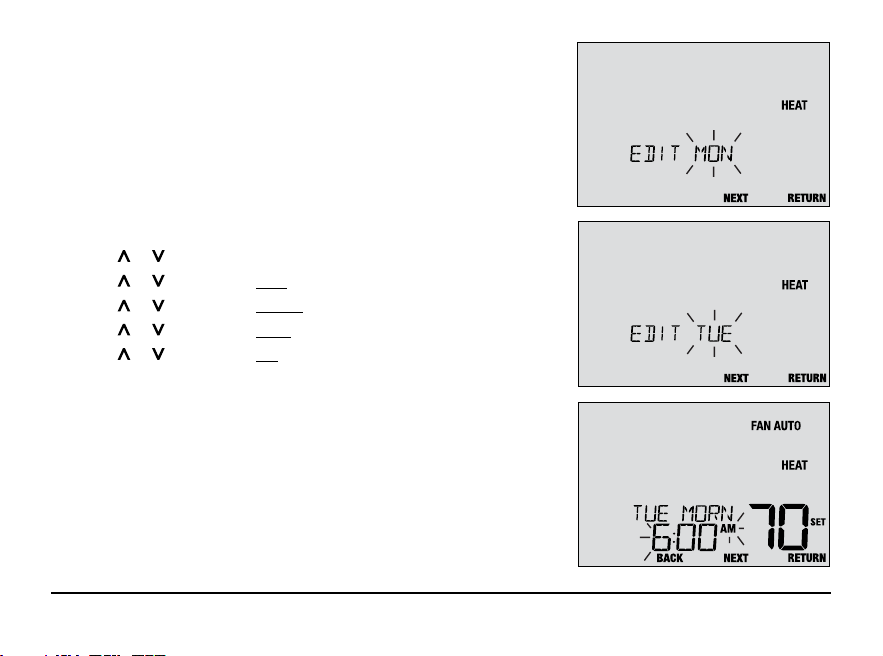
Setting a 7-Day program – Individual Days
(7-day residential or commercial programming mode only)
Available Daily Events
Residential mode: MORN, DAY, EVE, NITE
Commercial mode: OCC, UNOC
1. Press and release the PROG button.
2. Press SYSTEM to select HEAT or COOL.
3. Press or to select the day you want to program. Press NEXT.
4. Press or to adjust the hour for the first event. Press NEXT.
5. Press or to adjust the minute for the first event. Press NEXT.
6. Press or to adjust the temp for the first event. Press NEXT.
7. Press or to adjust the fan* for the first event. Press NEXT.
8. Repeat steps 4-7 for your remaining daily events.
9. If needed, repeat steps 3-8 to program additional days.
10. If needed, repeat steps 2-8 to program the opposite mode.
11. Press RETURN to exit.
* See “Programmable Fan Mode” in section 5.
19 User Manual
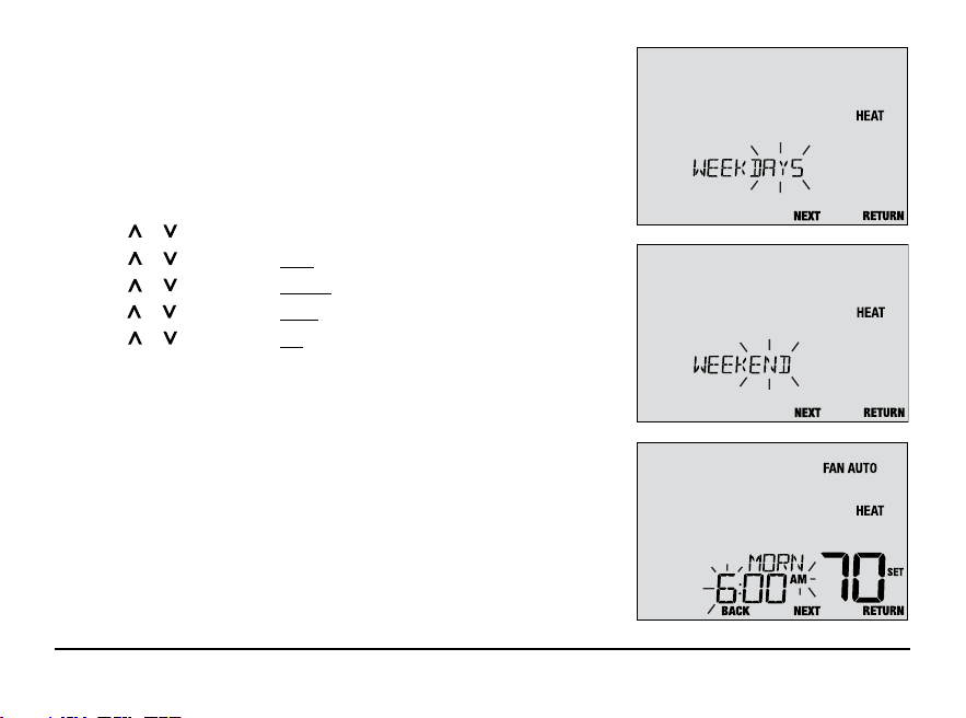
Setting a 5-2 Day Weekday/Weekend Program
(5-2 day residential programming mode only)
Available Daily Events: MORN, DAY, EVE, NITE
1. Press and release the PROG button.
2. Press SYSTEM to select HEAT or COOL.
3. Press or to select WEEKDAYS or WEEKEND. Press NEXT.
4. Press or to adjust the hour for the first event. Press NEXT.
5. Press or to adjust the minute for the first event. Press NEXT.
6. Press or to adjust the temp for the first event. Press NEXT.
7. Press or to adjust the fan* for the first event. Press NEXT.
8. Repeat steps 4-7 for your remaining daily events.
9. If needed, repeat steps 3-8 to program additional days.
10. If needed, repeat steps 2-9 to program the opposite mode.
11. Press RETURN to exit.
* See “Programmable Fan Mode” in section 5.
4
Operating Your Thermostat
Setting the SYSTEM Control Mode
The System Control has 5 modes of operation – COOL, OFF, HEAT, AUTO and EMR HEAT. The mode can be
selected by pressing the SYSTEM button to scroll through the different system modes.
NOTE: Depending on how your thermostat was configured, some system modes may not be available.
COOL Only your cooling system will operate.
OFF Heating and cooling systems are off.
HEAT Only your heating system will operate
AUTO The system will cycle between heating and
cooling automatically based on your temperature
set points. AUTO will be displayed with either
HEAT or COOL.
EMERGENCY
Operates a backup heat source
HEAT (EMR HEAT)
(Emergency Heat) for heat pump
systems only.
User Manual 20
21 User Manual
Setting the FAN Control Mode
The Fan Control has 4 modes of operation – AUTO, ON, CIRC and PROG. The mode can be selected by pressing
the FAN button to scroll through the different fan modes.
NOTE: Depending on how your thermostat was configured, some fan modes may not be available.
AUTO The system fan will run only when your heating
or cooling system is running.
ON The system fan stays on.
CIRC The system fan will run from time to time to
help circulate air and provide more even
temperature when the heating or cooling
system is not active.
PROG The system fan will function in the AUTO,
ON or CIRC modes depending on your
program schedule.
User Manual 22
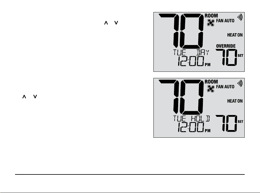
Temperature Adjustment
Temporary Adjustment (OVERRIDE) – Press or to adjust
the current set temperature. The set temperature will change
back to your programmed temperature a few hours later or
at the start of the next scheduled program event. OVERRIDE
will appear in the display during the entire override period.
Extended Adjustment (HOLD) – Press the HOLD button
to override all programming. You can continue to use
the or buttons to adjust the current set temperature.
Press HOLD again to resume the program schedule. You
can limit your hold time to 24-hours by adjusting User
Setting 14 in section 2.
NOTE: If your thermostat was configured to be
non-programmable, HOLD and OVERRIDE are
not available.
23 User Manual
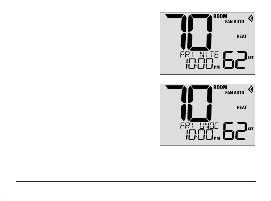
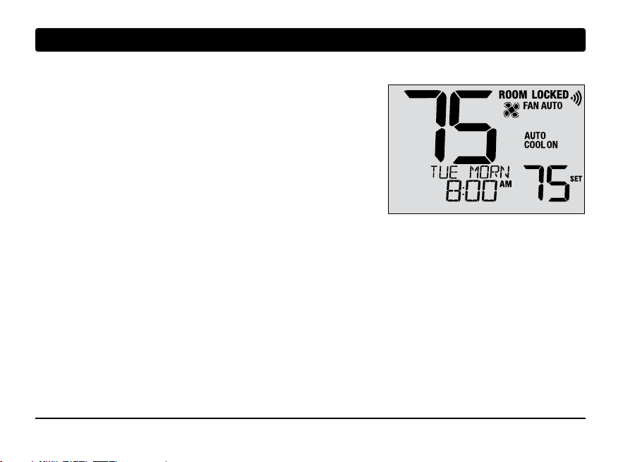
Program Event Indicators
Program event indicators appear in the display to let you
know what part of your current program is active.
• Residential Program Mode: MORN, DAY, EVE or NITE
• Commercial Program Mode: OCC (occupied) or
UNOC (unoccupied)
NOTE: If your thermostat was configured to be
non-programmable, or is in HOLD mode, you will
not see a Program Event or OVERRIDE indicator.
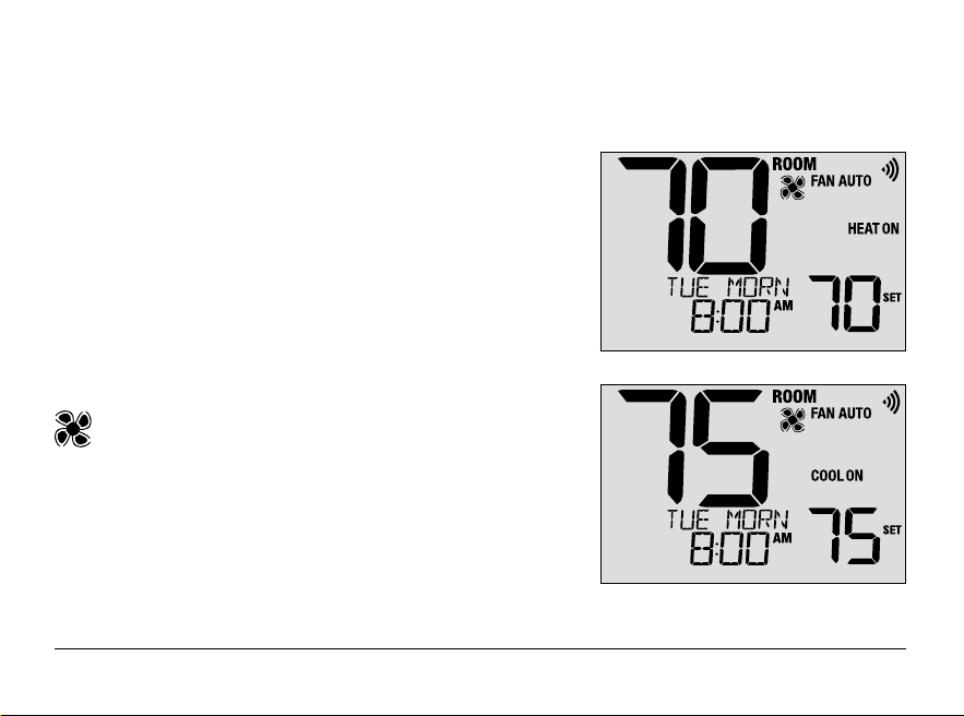
System Status and Maintenance Indicators
Status indicators are messages or symbols that appear in the display to let you know what function your system
is currently performing. They are also used to inform you of various service and maintenance functions.
HEAT ON The heating system is running.
COOL ON The cooling system is running.
HEAT ON AUX The auxiliary stage of heating is running
(multistage systems only).
EMERGENCY
The emergency heating system is
HEAT ON running (heat pump systems only).
Indicates that the system fan is running.
User Manual 24
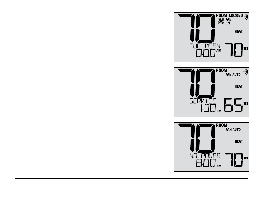
System Status and Maintenance Indicators (continued)
LOCKED Thermostat has been fully or partially locked.
See Locking and Unlocking thermostat, section 5.
SERVICE A user selectable service reminder for changing
the filter, UV bulb or humidifier pad has been
triggered. To set or reset these reminders, see
User Options, section 2.
NO POWER AC power to thermostat has been lost. Only available
if thermostat is hardwired and thermostat is configured
for power monitoring.
25 User Manual
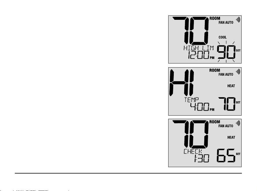
System Status and Maintenance Indicators (continued)
HIGH LIM Setpoint temperature has reached its
upper limit maximum.
LOW LIM Setpoint temperature has reached its
lower limit maximum.
HI TEMP Room temperature has risen above the
display range. Cooling will still operate to
help lower temperature.
LO TEMP Room temperature has fallen below the
display range. Heat will still operate to help
raise temperature.
CHECK Indicates that there is a potential problem with
SYSTEM your system. Contact a local service technician.
Display will alternate between CHECK / SYSTEM.
PM
User Manual 26
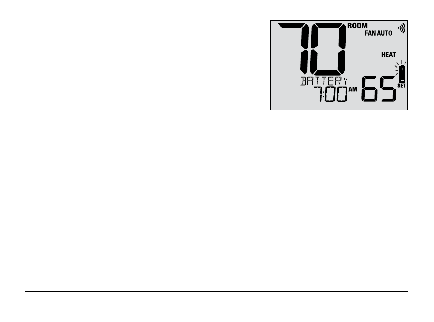
System Status and Maintenance Indicators (continued)
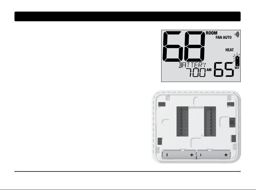
CHANGE If batteries are installed and they become
BATTERY low, the battery symbol appears in the display.
When the batteries become critically low, the
battery symbol will flash, and CHANGE / BATTERY
will alternate in the display (see “Changing the
Batteries” in section 6).
27 User Manual
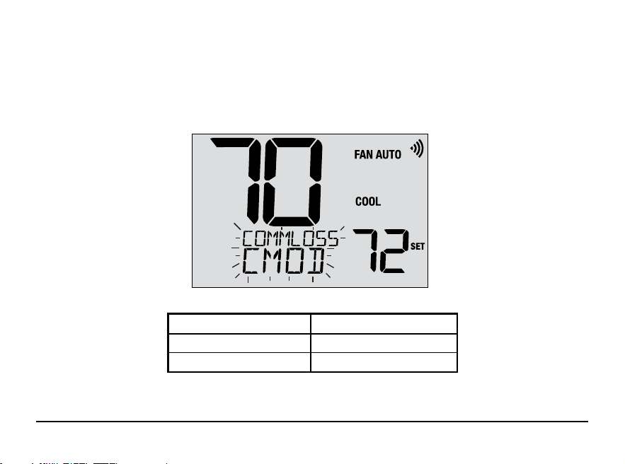
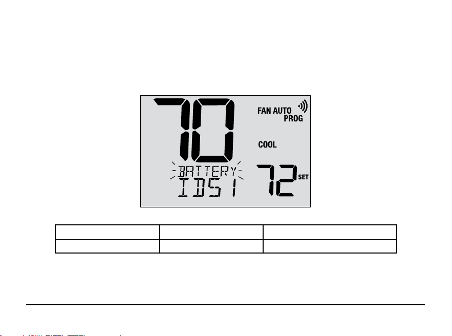
Communication Loss
If communication with a wireless device has been lost, the display screen will alternate between COMM LOSS
and the name of the device that has lost communication. See Table 1 for a list of possible device names.
The device will attempt to reconnect with the thermostat automatically, however you can also manually attempt
reconnection by pressing and holding the CONNECT button for 3 seconds on the device (see Wireless Setup Guide).
IDS1, IDS2, IDS3 or IDS4 Remote Indoor Sensor 1-4
ODS Remote Outdoor Sensor
Control Module (see page 8)
CMOD
Table 1
User Manual 28
Remote Sensor - Low Batteries
If batteries become low in a wireless remote sensor, the display screen will alternate between CHANGE BATTERY
and
the name of the sensor that has the low batteries. See Table 2 below for a list of possible sensor names. Replace
the batteries in the remote sensor as soon as possible (see wireless remote sensor instructions). After replacing
the batteries, the remote sensor will try to automatically reconnect. The reconnection may take up to 15 minutes.
IDS1, IDS2, IDS3 or IDS4 Remote Indoor Sensor 1-4 Requires 2 AA Alkaline Batteries
ODS Remote Outdoor Sensor Requires 2 AA Lithium Batteries
Table 2
29 User Manual
5
Additional Operating Features
Auto Changeover Mode
When Auto Changeover mode is enabled and selected, the system
automatically switches between heating and cooling when the
room temperature meets the current heating or cooling set points.
To operate properly, the thermostat maintains a forced separation
between the heating and cooling setpoints to prevent these systems
from working against each other. If a setting is made in either
heating or cooling which violates the forced separation, the opposite
mode will adjust up or down accordingly to maintain the current
forced separation.
Select Auto Changeover Mode by pressing the SYSTEM button until AUTO HEAT or AUTO COOL appears in the
display. Whichever system was running last will remain in the display until the opposite system runs.
Adaptive Recovery Mode (ARM
TM
)
If enabled, Adaptive Recovery Mode attempts to achieve your desired heating or cooling temperature at the time
you have set in your current program schedule, after a setback period. For example, if you set your heat down to
62° at night and have a set point of 70° scheduled for 7:00 AM, the thermostat may turn on your heating system
early in order achieve a temperature of 70° by 7:00 AM.
This feature does not operate when the thermostat is in HOLD mode; if the program is temporarily overridden or
if emergency heat is selected on a multistage heat pump system.
User Manual 30
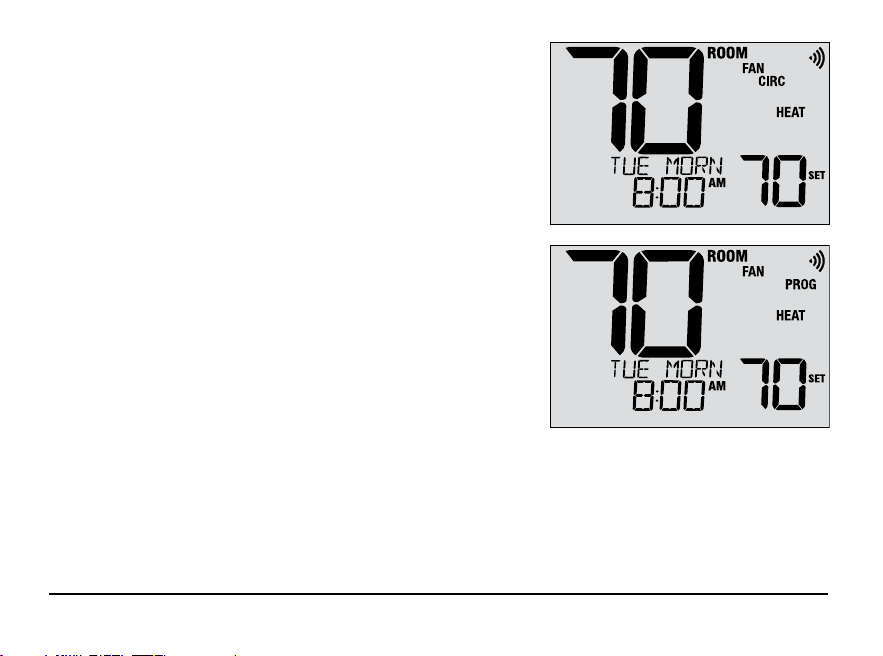
Circulating Fan Mode
Circulating Fan Mode is selected by touching the FAN button until
CIRC appears in the display. When in CIRC mode the fan operates
as required by the heating and cooling system (just like AUTO mode).
When heating or cooling is not active, fan will run as needed to
ensure a 35% minimum run time.
Programmable Fan Mode
Programmable Fan Mode allows the user to run the system fan in
the AUTO, ON or CIRC mode during a selected program event.
This selection is made during the programming process
(See “Setting Your Program Schedule” in section 3).
Programmable Fan is selected by pressing the FAN button until
FAN PROG appears in the display. It is not available if the
thermostat was configured to be Non-Programmable, however
it will still function if the thermostat is placed into HOLD mode.
Compressor Protection
This thermostat includes an automatic compressor protection delay to avoid potential damage to your system
from short cycling. This feature activates a short delay after turning off the system compressor.
Additionally, for multistage heat pump systems, this thermostat provides cold weather compressor protection by
locking out the compressor stage(s) of heating for a period of time after a power outage greater than 60 minutes.
During this lockout period, the thermostat will operate the auxiliary stage of heating.
31 User Manual
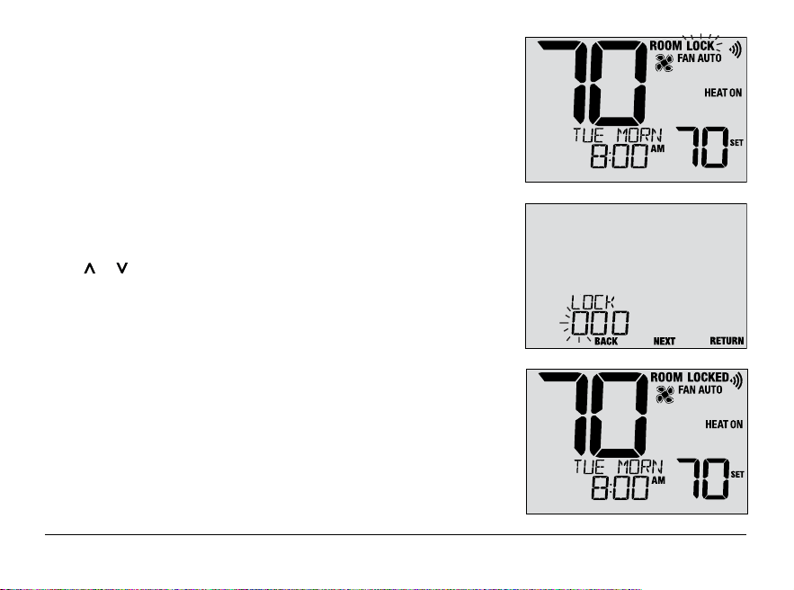
Locking and Unlocking the Thermostat
Your 3-digit Lock Code is set in the User Settings portion of this
manual (section 2). Once the code is set, the thermostat can be
locked or unlocked at any time by entering that code.
To lock or unlock the thermostat, press and hold the PROG and
HOLD buttons together for 5 seconds. While holding these buttons,
LOCK will flash in the display (Figure 1).
The screen will change displaying LOCK CODE 000 (Figure 2).
Press or to enter the first digit of your lock code and then
press the NEXT button to advance to the next digit. Repeat this
process to enter the second and third digit of your lock code.
After entering the third digit, press NEXT to advance to the next
User Setting or RETURN to exit.
If you entered a valid code, the thermostat will be locked or
unlocked (depending on its previous state). When locked, the
word LOCKED appears in the display (Figure 3). If an invalid code
is entered, WRONG CODE will briefly appear in the display.
Figure 1
Figure 2
Figure 3
User Manual 32
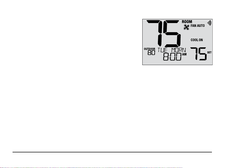
Figure 2
Figure 3
Outdoor
Remote Sensing
Outdoor remote sensing is achieved by installing a Braeburn
®
remote outdoor sensor (model 5490 or 7490).
When properly connected, the current outdoor temperature can be
viewed in the left side of the display. An outdoor sensor can also
used in certain Heat Pump applications for heating and
cooling balance points.
Indoor
Remote Sensing
Indoor remote sensing is achieved by installing a Braeburn
remote indoor sensor (model 5390 or 7390).
If
a Braeburn indoor remote sensor was installed and properly configured, the thermostat will sense temperature
at a remote location or an average of a remote location and the thermostat location.
NOTE: For instructions on connecting wireless sensors, please see the Wireless Setup Guide.
33 User Manual
6
Thermostat Maintenance
Changing the Batteries
Depending on your installation, this thermostat may be equipped with
two (2) “AA” type alkaline batteries.
If batteries are installed and they become low, the battery symbol
appears in the display. When the batteries become critically low,
the battery symbol will flash, and CHANGE / BATTERY will alternate
in the display.
To change your batteries:
1. Remove thermostat body by gently pulling it from base.
2. Remove old batteries and replace with new batteries.
3. Make sure to correctly position the (+) and (-) symbols.
4. Gently push thermostat body back onto base.
NOTE: We recommend replacing the thermostat batteries
annually or if the thermostat will be unattended for
an extended period of time.
Thermostat Cleaning
Never spray any liquid directly on the thermostat. Spray
your
cleaning liquid on a soft cloth and then proceed to
clean the screen
with the damp cloth. Only use water or
household glass cleaner. Never use any abrasive cleansers
to clean your thermostat.
User Manual 34

Regulatory Statements
This equipment has been tested and found to comply with the limits for a Class B digital device, pursuant to Part 15 of the FCC Rules. These limits are
designed to provide reasonable protection against harmful interference in a residential installation. This equipment generates uses and can radiate
radio frequency energy and, if not installed and used in accordance with the instructions, may cause harmful interference to radio communications.
However, there is no guarantee that interference will not occur in a particular installation. If this equipment does cause harmful interference to radio or
television reception, which can be determined by turning the equipment off and on, the user is encouraged to try to correct the interference by one or
more of the following measures:
• Reorient or relocate the receiving antenna.
• Increase the separation between the equipment and receiver.
• Connect the equipment into an outlet on a circuit different from that to which the receiver is connected.
• Consult the dealer or an experienced radio/TV technician for help.
Changes or modifications not expressly approved by the party responsible for compliance could void the user’s authority to operate the equipment.
This device complies with part 15 of the FCC Rules. Operation is subject to the following two conditions: (1) This device may not cause harmful
interference, and (2) this device must accept any interference received, including interference that may cause undesired operation.
This device complies with Industry Canada’s licence-exempt RSSs. Operation is subject to the following two conditions:
(1) This device may not cause interference; and
(2) This device must accept any interference, including interference that may cause undesired operation of the device.
Cet appareil est conforme aux CNR exempts de licence d’Industrie Canada. Son fonctionnement est soumis aux deux conditions suivantes :
(1) Ce dispositif ne peut causer des interf é rences ; et
(2) Ce dispositif doit accepter toute interf é rence , y compris les interf é rences qui peuvent causer un mauvais fonctionnement de l’appareil.
La operación de este equipo está sujeta a las siguientes dos condiciones: (1) es posible que este equipo o dispositivo no cause interferencia perjudicial
y (2) este equipo o dispositivo debe aceptar cualquier interferencia, incluyendo la que pueda causar su operación no deseada.

Braeburn Systems LLC
2215 Cornell Avenue • Montgomery, IL 60538
Technical Assistance: www.braeburnonline.com
Call us toll-free: 866-268-5599 (U.S.)
630-844-1968 (Outside the U.S.)
©2024 Braeburn Systems LLC • All Rights Reserved.
8500-110-02
For more information, visit www.braeburnonline.com
Limited Warranty
When installed by a professional contractor, this product is backed by a 5 year limited warranty. Limitations apply. For limitations, terms
and conditions, you may obtain a full copy of this warranty. Visit us online: www.braeburnonline.com/warranty, phone us: 866.268.5599
or write us: Braeburn Systems LLC, 2215 Cornell Avenue, Montgomery, IL 60538.
55
YEAR
WARRANTY
LIMITED