Before using this product:
Please read this user manual carefully in order to ensure your safety
and the proper operation of this product. Keep for future reference.
TTL
TTL Li-ion Camera Flash
Made in China
:2
:0755-29609320(8062):0755-25723423:godox@godox.com
godox.com
Add: Building 2, Yaochuan Industrial Zone, Tangwei Community,
Fuhai Street, Bao’an District, Shenzhen 518103, China
Tel: +86-755-29609320(8062) Fax: +86-755-25723423
GODOX Photo Equipment Co., Ltd.
705-V8603F-00
INSTRUCTION MANUAL
QCPASS
Always keep this product dry. Do not use in rain or in damp
conditions.
Do not disassemble. Should repairs become necessary, this
product must be sent to an authorized maintenance center.
Keep out of reach of children.
Stop using this product if it breaks open due to extrusion, falling
or strong hit. Otherwise, electric shock may occur if you touch
the electronic parts inside it.
Do not fire the flash directly into the eyes (especially those of
babies) within short distances. Otherwise visual impairment
may occur.
Do not use the flash unit in the presence of flammable gases,
chemicals and other similar materials. In certain circumstance,
these materials may be sensitive to the strong light emitting
from this flash unit and fire or electromagnetic interference may
result.
Do not leave or store the flash unit if the ambient temperature
reads over 50℃. Otherwise the electronic parts may be
damaged.
Turn off the flash unit immediately in the event of malfunction.
Thank you for purchasing this product.
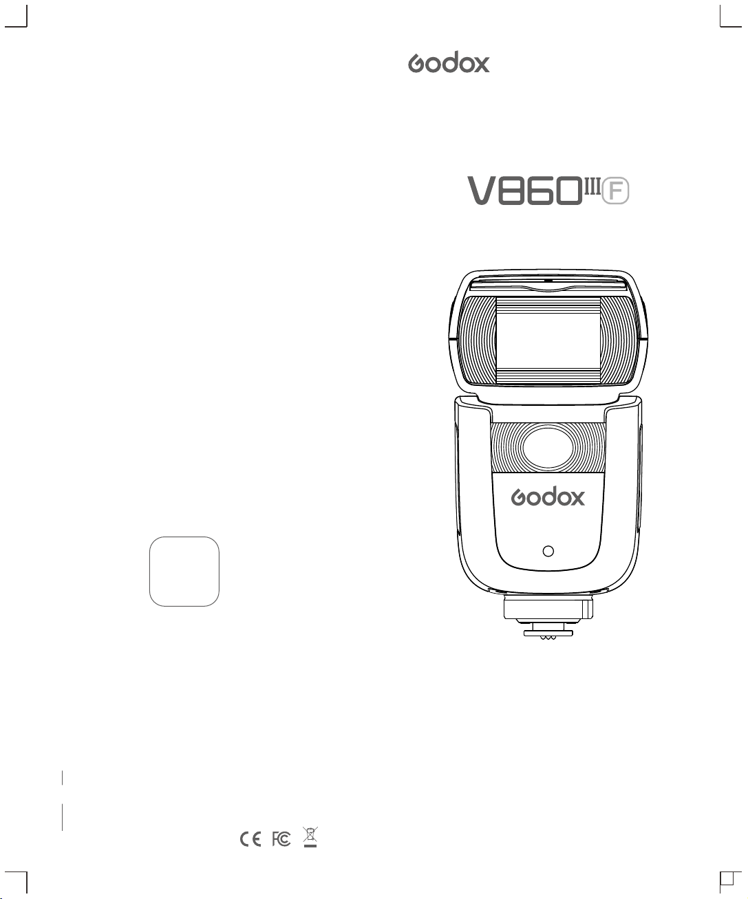
This V860IIIF camera flash applies to FUJIFILM series cameras
and is compatible with TTL autoflash. With this TTL compatible flash,
your shooting will become simpler. You can easily achieve a correct
flash exposure even in complex light-changing environments. This
camera flash features:
● Achieve soft, even and more creative light effects. It has a 2W LED
modeling lamp, which can be used off the camera.
● Approx. GN60 (m ISO 100, @200mm), 81 steps from 1/1 to 1/256.
● 6 max 480Pro 2 00mAh Li-ion Battery- .1.5s recycle- full power pops.
● Fully support FUJIFILM TTL camera flash. Workable as
Transmitter or Receiver unit in a wireless flash group.
● Use dot-matrix LCD panel to make clear and convenient
operations.
● With built-in 2.4GHz wireless remote system to support
transmitting and receiving.
● Provided multiple functions, include HSS (up to 1/8000s), FEC,
FEB, etc.
● Stable consistency and color temperature with good even lighting.
● Support with firmware upgrade.
Warning
Foreword
- 29 - - 30 -

Foreword
Warning
Name of Parts
Body
Control Panel
Dot-matrix LCD Panel
LCD Panel in Three Modes
What's in the Box of V860IIIF Kit?
Separately Sold Accessories
Battery
LED Modeling Lamp
Attaching to a Camera
Power Management
Flash Mode — TTL Autoflash
FEC (Flash Exposure Compensation)
High-Speed Sync
Second-Curtain Sync
M: Manual Flash
Multi: Stroboscopic Flash
Wireless Flash Shooting: Radio (2.4G) Transmission
Wireless Settings
Group Mode Selection
Setting the Communication Channel
Wireless ID Settings
Scan the Spare Channel
Fully Automatic Wireless Flash Shooting
M: Wireless Flash Shooting with Manual Flash
Multi: Wireless Flash Shooting with Manual Flash
TTL/M Shortcut Function
Lock Function
Other Applications
Sync Triggering
Modeling Flash
Auto Focus Assist Beam
Bounce Flash
ZOOM: Setting the Flash Coverage
Low Battery Warning
C.Fn: Setting Custom Functions
Protection Function
Technical Data
Troubleshooting
Firmware Upgrade
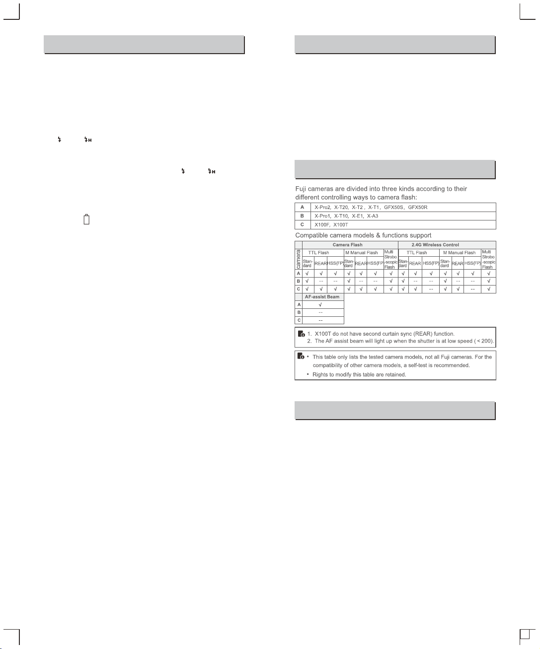
Compatible Camera Models
Maintenance
Contents
Conventions used in this Manual
● This manual is based on the assumption that both the camera
and camera flash’s power switches are powered on.
● Reference page numbers are indicated by “p.**”.
● The following alert symbols are used in this manual:
The Caution symbol gives supplemental information.
The Note symbol indicates a warning to prevent shooting
problem.
Pioneering TTL Li-ion Round Head Camera Flash
- 31 - - 32 -
29
30
33
37
38
38
38
39
41
42
43
50
51
52
53
54
55
56
56
56
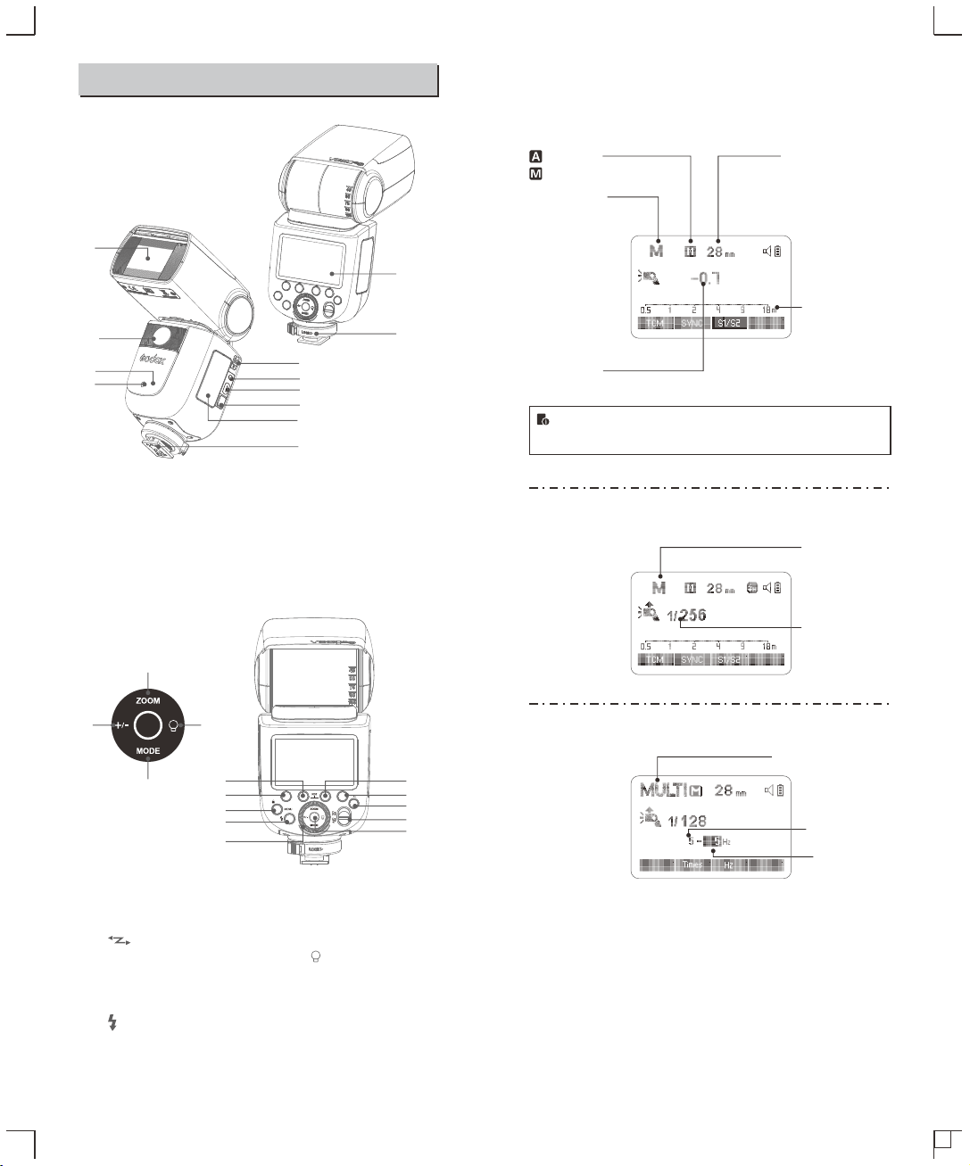
● LCD Panel
Name of Parts
(1)TTL Autoflash
Zoom : zoom display (Page 51)
: Automatic
: Manual(Page 41)
TTL : TTL
autoflash
Focus length (Page 1)5
Distance indicator
display
Flash exposure
compensation amount
(2)M Manual Flash
● The display will only show the settings currently applied.
● When a button or dial is operated, the LCD panel illuminated.
M : Manual flash
Manual flash output
(3) Multi Flash
Multi: Stroboscopic flash
Number of flashes
Flash frequency
- 33 - - 34 -
01. Flash Head
02. LED Modeling Lamp
03. Focus Assist Beam
04. Wireless Sensor
05. Sync Cord Jack
06. Type-C USB Port
07. Battery Remove Button
08. Hotshoe
09. LCD Panel
10. Hotshoe Fixing Buckle
11. Lithium Battery
12. TTL/M Shortcut
● Body
● Control Panel
09
05
07
08
04
03
01
06
02
10
12
11
19
20
22 21
18
24
25
16
14
13
26
17
23
15
13. <MENU>Flash Menu
Button/Locking Button
14. < >Wireless Selection
Button
15. Select Dial
16. Set Button
17. ON/OFF Power Switch
18. < > Test Button / Flash
Ready Indicator
19. <ZOOM> Focus Length
Setting
20. <MODE>Mode Selection
Button
21. < >Modeling Lamp Setting
22. <+/->Power Output
23. Function Button 1
24. Function Button 2
25. Function Button 3
26. Function Button 4
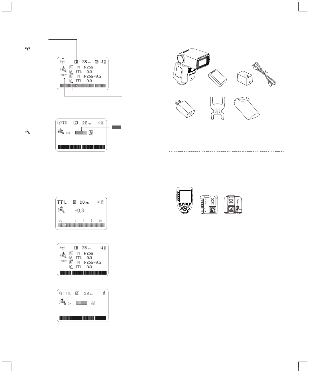
Firing group
Flash mode
Channel
: Radio transmission
wireless shooting
(4) Radio Transmission Shooting
● Transmitter Unit (TX)
● Receiver Unit (RX)
: Receiver
: Receiver icon
● LCD Panel in Three Modes
● Attached to the Camera
● 2.4G Radio Transmission: As a Transmitter Unit
● 2.4G Radio Transmission: As a Receiver Unit
● What’s in the Box of V860IIIF Kit?
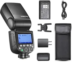
1. Flash Unit 2. Lithium Battery 3. USB Battery Charger
4. USB Cable 5. Charger 6. Mini Stand
7. Protection Case 8. Instruction Manual
● Separately Sold Accessories
The product can be used in combination with the following accessories
sold separately, so as to achieve best photography effects:
XProF, X2T-F & X1F TTL wireless flash trigger, etc.
- 35 - - 36 -
Note: The flash unit attached to the camera is referred to as the "Transmitter",
and other flash units controlled wirelessly are referred to as "Receivers".
RX
RX
RX
Gr CH
M A B C
Gr CH
1 2
3
6
7
5
● Features
1. This flash unit uses Li-ion battery which has long runtime.
The available charge-and-discharge times are 480.
2. It is reliably safe. The inner circuit is against overcharge,
overdischarge, overcurrent, and short circuit.
3. Take only 3.5 hours to fully charge the battery by using the
standard battery charger.
● Cautions
1. Do not short circuit.
2. Do not expose to rain or immerse into water. This battery is not
water proof.
3. Keep out of reach of children.
4. No over 24 hours’ continuous charging.
5. Store in dry, cool, ventilated places.
6. Do not put aside or into fire.
7. Dead batteries should be disposed according to local regulations.
8. If the battery had ceased using for over 3 months, please make a
full recharge.
9. If do not use it for a long time, please charge the battery to
approx. 60% before placing it.
10. It is recommended to use a brand-new battery after charging
and discharging over 500 times or being used over 3 years.
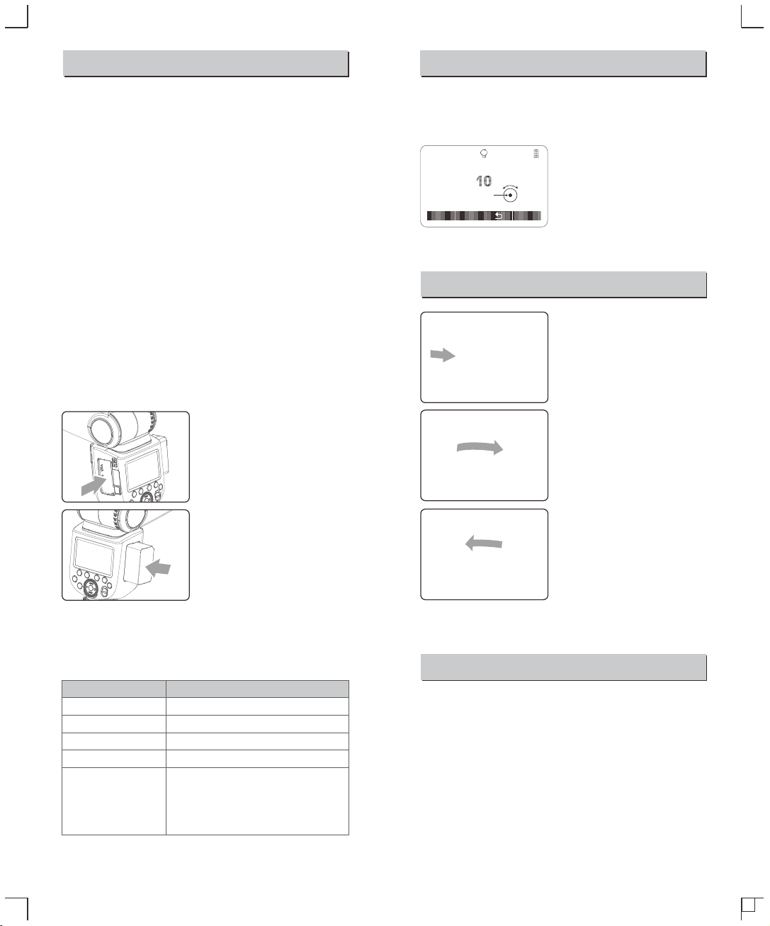
● Loading and Unloading the Battery
Battery
To unload the battery, hold
1 down the battery remove
button and push the battery
downwardly to take it out.
According to the triangle sign
2 on the battery pack, insert it
into the compartment until a
white knob locks the battery
with a click sound.
● Battery Level Indication
Make sure the battery pack is securely loaded in the flash. Check
the battery level indication on the LCD panel to see the remaining
battery level.
Battery Level Indication
3 grids
2 grids
1 grid
Blank grid
Blinking
Attaching to a Camera
Attach the Camera Flash.
1
● Rotate the hotshoe fixing
buckle to the left and insert
the camera flash into the
camera's hotshoe.
Secure the Camera Flash.
2
● Rotate the hotshoe fixing
buckle to the right until it
locks up.
Detach the Camera Flash.
3
● Press the button and
rotate the hotshoe fixing
buckle to the left until it is
loosened.
Power Management
Use ON/OFF Power Switch to power the flash unit on or off. Turn
off if it will not be used for an extended period of time. Setting as a
transmitter flash, it will turn the power off automatically after a
certain period (approx. 90 seconds) of idle use. Pressing the
camera shutter halfway or pressing any flash button will wake up
the flash unit. Setting as a receiver flash, it will enter sleep mode
after a certain period (adjustable, 60 minutes by default) of idle use.
Pressing any flash button will wake it up.
The battery level is going to be used out
immediately. And the flash will auto power off
in 1 minute.
Note: Please recharge the battery as soon as
possible (within 10 days). Then, the battery can be
used or be placed for long period.
Meaning
Full
Middle
Low
Lower battery, please recharge it.
Press the Modeling Lamp Setting button to set the modeling lamp.
Short press the Set Button to turn on or off the modeling lamp.
When turning the modeling lamp on, turn the select dial to set its
brightness. There are 10 levels(01~10) for choice.
- 37 - - 38 -
LED Modeling Lamp
MODEL
ON/OFF
Flash Mode — TTL Autoflash
This flash has three flash modes: TTL, Manual (M), and Multi
(Stroboscopic). In TTL mode, the camera and the flash will work
together to calculate the correct exposure for the subject and the
background. In this mode, multiple TTL functions are available:
FEC, HSS, second curtain sync, modeling flash.
* Press < MODE > Mode Selection Button and three flash modes
will display on the LCD panel one by one with each pressing.
TTL Mode
Press < MODE > Mode Selection Button to enter TTL mode. The
LCD panel will display.
● Press the camera release button halfway to focus. The aperture
and effective flash range will be displayed in the viewfinder.
● When the shutter button is fully pressed, the flash will fire a pre-
flash that the camera will use to calculate exposure and flash
output the instant before the photo is taken.
FEC: Flash Exposure Compensation
With FEC function, this flash can adjust from -3 to +3 in 1/3rd stops.
It is useful in situations where minor adjusting of the TTL system is
needed based on the environment.
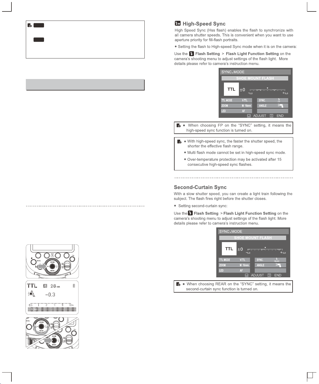
Setting FEC:
Set the flash exposure
2 compensation amount.
● Turn the Select Dial to set
the amount.
● “0.3”means 1/3 step,
“0.7”means 2/3 step.
● To cancel the flash
exposure compensation,
set the amount to “+0”.
Press Set Button again to
3 confirm the setting.
Press the <+/-> button. The
1 flash exposure compensation
amount will be highlighted on
the LCD panel.
C.Fn
C.Fn
Disabling Auto Power Off function is recommended when
the flash is used off camera. (C.Fn-STBY, Page 52)
Receiver Auto Power Off Timer is set to 60 minutes by
default. Another option “30 minutes” is available. (C.Fn-
RX STBY, Page 52)
- 39 - - 40 -
The flash output is adjustable from 1/1 full power to 1/256th power
in 1/10th stop increments. To obtain a correct flash exposure, use a
hand-held flash meter to determine the required flash output.
M: Manual Flash
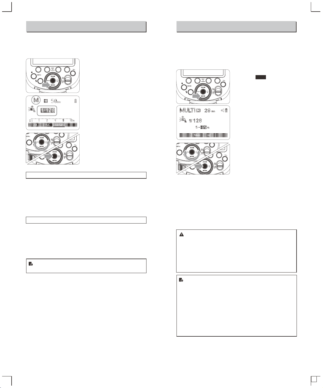
Press < MODE > button so
1 that < M > is displayed.
Press the <+/-> button and turn
2 the Select Dial to choose a
desired flash output amount.
Press Set Button again to
3 confirm the setting.
Optic S1 Secondary Unit Setting
In M manual flash mode, press <S1/S2> button so that this flash can
function as an optic S1 secondary flash with optic sensor. With this
function, the flash will fire synchronously when the main flash fires,
the same effect as that by the use of radio triggers. This helps create
multiple lighting effects.
Optic S2 Secondary Unit Setting
Press <S1/S2> button so that this flash can also function as an optic
S2 secondary flash with optic sensor in M manual flash mode. This
is useful when cameras have pre-flash function. With this function,
the flash will ignore a single “preflash” from the main flash and will
only fire in response to the second, actual flash from the main unit.
● S1 and S2 optic triggering is only available in M manual
flash mode.
Press the <+/-> button and
3 turn the Select Dial to choose
a desired flash output.
● After you finish the setting,
press Set Button and all the
settings will be displayed.
Multi: Stroboscopic Flash
With stroboscopic flash, a rapid series of flashes is fired. It can be
used to capture a multiple images of a moving subject in a single
photograph.
You can set the firing frequency (number of flashes per sec.
expressed as Hz), the number of flashes, and the flash output.
Press <MODE> button so
1 that < > is displayed.
Calculating the Shutter Speed
During stroboscopic flash, the shutter remains open until the firing
stops. Use the formula below to calculate the shutter speed and set
it with the camera.
For example, if the number of flashes is 10 and the firing frequency is
5 Hz, the shutter speed should be at least 2 seconds.
Number of Flashes / Flash Frequency = Shutter Speed
To avoid overheating and deteriorating the flash head, do not
use stroboscopic flash more than 10 times in succession.
After 10 times, allow the camera flash to rest for at least 15
minutes. If you try to use the stroboscopic flash more than 10
times in succession, the firing might stop automatically to
protect the flash head. If this happens, allow at least 15
minutes’ rest for the camera flash.
● Stroboscopic flash is most effective with a highly reflective
subject against a dark background.
● Using a tripod and a remote control is recommended.
● A flash output of 1/1 and 1/2 cannot be set for stroboscopic
flash.
● Stroboscopic flash can be used with“buLb”.
● If the number of flashes is displayed as “--”, the firing will
continue until the shutter closes or the battery is
exhausted. The number of flashes will be limited as shown
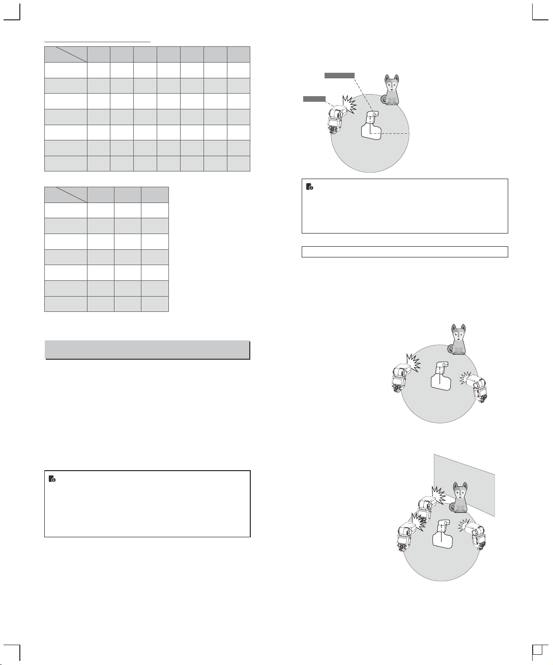
by the following table.
Multi
Set the flash frequency and
2 flash times.
● Press the Function Button
2 <Times> to select the
flash times. Turn the Select
Dial to set the number.
● Press the Function Button
3 <Hz> to select the flash
frequency. Turn the Select
Dial to set the number.
- 41 - - 42 -
Hz
Maximum Stroboscopic Flashes:
Flash
output
Hz
Flash
output
Wireless Flash Shooting: Radio (2.4G) Transmission
● You can set up five receiver groups for TTL autoflash shooting.
With TTL autoflash, you can easily create various lighting effects.
● Any flash settings for the receiver units(auto flash, manual flash
and stroboscopic flash) on the transmitter flash in TTL mode will
be automatically sent to the receiver units. So the only thing you
need to do is to set the transmitter unit for each receiver group
without any operation for the receiver units at all during the
shooting.
● This flash can work in TTL /M /Multi/ OFF flash modes when set
as a transmitter unit.
Note:
● Even with multiple receiver units, the X series flash trigger
can control all of them via wireless.
● In this user manual, “transmitter unit” refers to the camera
flash on a camera and “receiver unit” will be controlled by
the transmitter unit.
1/4
1/8
1/16
1/32
1/64
1/128
1/256
1
8
14
30
60
90
90
90
2
6
14
30
60
90
90
90
3
4
12
30
60
90
90
90
4
3
10
20
50
80
90
90
5
3
8
20
50
80
90
90
6-7
2
6
20
40
70
90
90
8-9
2
5
10
30
60
80
80
1/4
1/8
1/16
1/32
1/64
1/128
1/256
10
2
4
8
20
50
70
70
20-50
2
4
8
16
30
40
40
60-100
2
4
8
12
20
40
40
Positioning and Operation Range (Example of wireless flash
shooting)
● Autoflash Shooting with One Receiver Unit
● Use the supplied mini stand to position the receiver unit.
● Before shooting, perform a test flash and test shooting.
● The transmission distance might be shorter depending on
the conditions such as positioning of receiver units, the
surrounding environment and whether conditions.
● Auto Shooting with Two Receiver Groups
● Auto Shooting with Three Receiver Groups
You can divide the receiver units into two or three groups and
perform TTL autoflash while changing the flash ratio (factor). In
addition, you can set and shoot with a different flash mode for each
firing group, for up to 5 groups.
Wireless Multiple Flash Shooting
- 43 -
- 44 -
Transmission distance is about 100m.
A
B
TRANSMITTER
RECEIVER
A
B
C
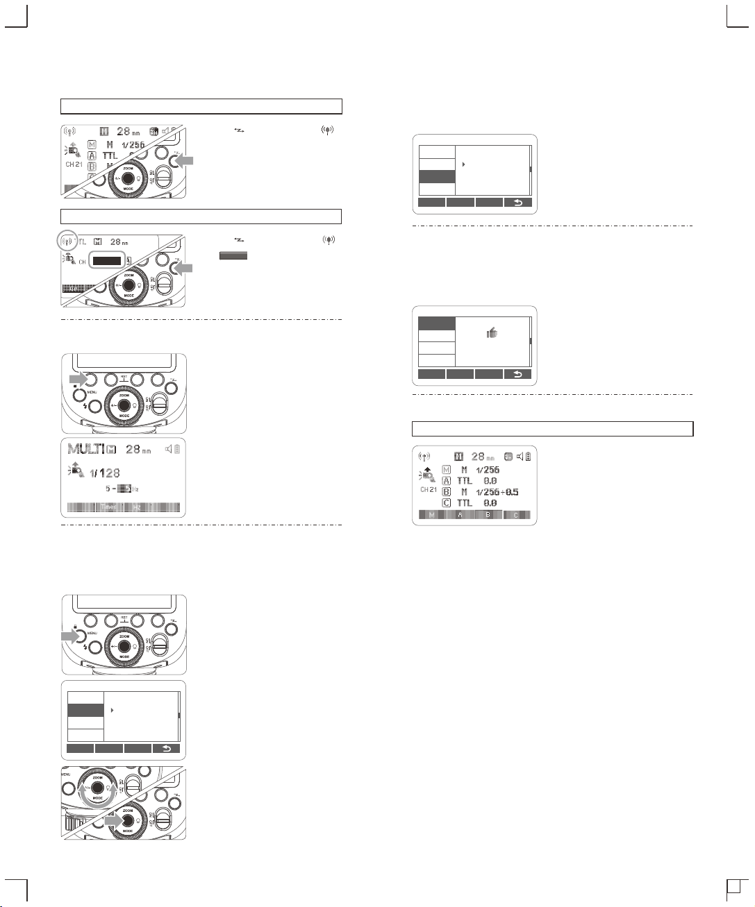
Press < > button so that < >
or < > are displayed on
the LCD panel.
Receiver Unit Setting
Transmitter Unit Setting
Press < > button so that < >
is displayed on the LCD panel.
2. Group Mode Selection
Short press the Function
1 Button 1 and <M> group
can be changed in
OFF/TTL/M. Choose one of
them as transmitter unit's
flash mode.
Short press the <MODE>
2 button to gain Multi mode.
1. Wireless Settings
You can switch between normal flash and wireless flash. For normal
flash shooting, be sure to set the wireless setting to OFF.
3. Setting the Communication Channel
If there are other wireless flash systems nearby, you can change the
channel IDs to prevent signal interference. The channel IDs of the
transmitter unit and the receiver unit(s) must be set to the same.
Press <MENU> Button to
1 enter C.Fn CH setting.
In C.Fn CH, turn the Select
2 Dial to choose channel ID
from 1 to 32.
Press the Set Button to
3 confirm.
4. Wireless ID Settings
Change the wireless channels and wireless ID to avoid interference
for it can only be triggered after the wireless IDs and channels of the
transmitter unit and the receiver unit are set to the same.Press the
<MENU> button to enter C.Fn ID. Press the Set Button to choose OFF
channel expansion shutdown, and choose any figure from 01 to 99.
5. Scan the Spare Channel
To avoid the interference of using the same channel by others, this
function can be used: enter the C.Fn settings and find the SCAN
option. When setting it to START, it will scan from 1% to 100%. And
the 8 spare channels will be displayed after the scan is completed.
6. TTLFully Automatic Wireless Flash Shooting
Using Automatic Wireless Flash with a Single Receiver Unit
Transmitter Unit Setting
1
● Attach a camera V860IIIF
flash on the camera and
set it as the transmitter
unit.
● M/A/B/C can be set as TTL
mode independently.
C.Fn Ver 0.5
CLEAR
CH
ID
BEEP
STBY
07
SCAN
C.Fn Ver 0.5
CLEAR
CH
ID
BEEP
SCAN
22 08 32 23
30 21 07 06
C.Fn Ver 0.5
CLEAR
CH
ID
BEEP
STBY
99
SCAN
- 45 -
- 46 -
RX
RX
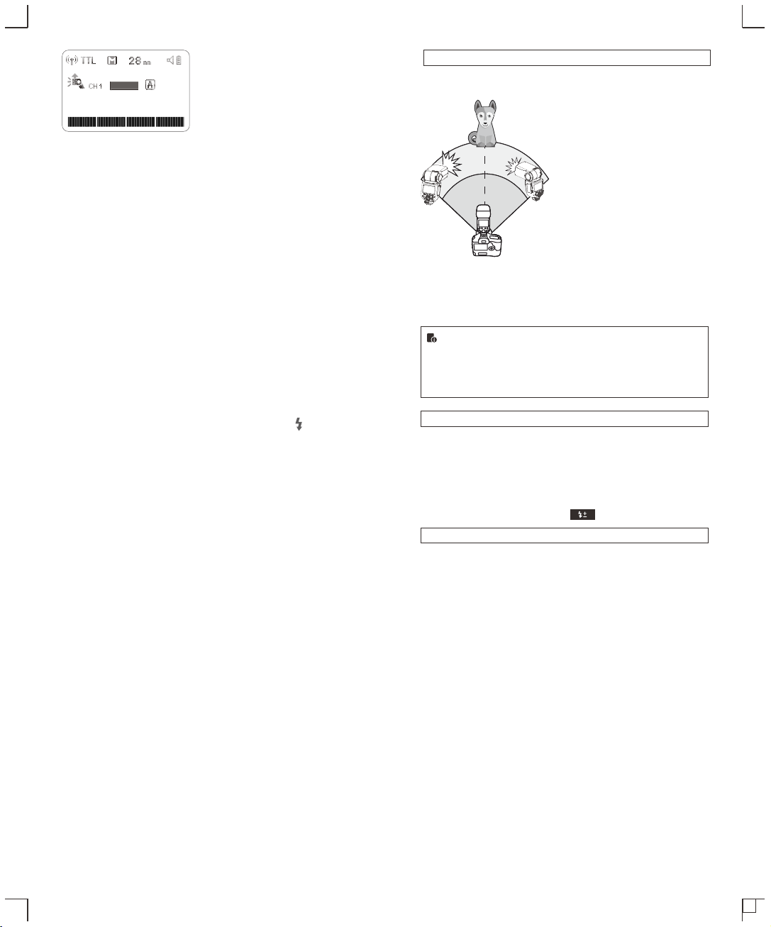
Receiver Unit Setting
2 ● Set the V860IIIF that to be
controlled as the wireless
receiver unit.
● The receiver unit can be
set as A/B/C/D/E.
Check the communication
3 channel.
● If the transmitter unit and
receiver unit(s) are set to a
different channel, set them
to the same channel.
(Page 45)
Check that the flash is
5 ready.
● Check that the transmitter
flash ready indicator is
lightened.
Check the flash operation.
6 ● Press the transmitter unit’s
Test Button < >.
● Then, the receiver unit will
fire. If not, adjust the
receiver unit’s angle toward
the transmitter unit and
distance from the
transmitter unit.
Position the camera and
4 flashes.
● Position the camera and
flashes as the picture
shows. (Page 44)
Using Automatic Wireless Flash with Multiple Receiver Units
When stronger flash output or
more convenient lighting operation
is needed, increase the number of
receiver units and set it as a
single receiver unit.
To add receiver units, use the
same steps as setting “automatic
wireless flash with a single
receiver unit”. Any flash group can
be set (A/B/C/D/E).
When the number of receiver units
is increased and the transmitter
unit flash firing is ON, automatic
control is implemented to make all
groups of flashes fire the same
flash output and ensure the total
flash output up is to standard
exposure.
● If the receiver unit’s auto power off function is workable, press the
transmitter unit’s test button to power it on. Please note that test firing is
unavailable during the camera’s regular metering time.
● The effective time of receiver auto power off is changeable. (C.Fn-RX
STBY Page 55)
Using Fully Automatic Wireless Flash
The FEC and other settings that set on the transmitter unit will also
be appeared on the receiver unit automatically. The receiver unit
does not need any operation. Use the following settings to make
wireless flashes according to the same methods with normal flash
shooting.
● Flash Exposure Compensation ( Page 39)
About Transmitter Unit
Use two or more transmitter units. By preparing several cameras
that with transmitter units flash attached, cameras can be changed
in shooting while keeping the same lighting source (receiver unit).
- 47 -
- 48 -
RX
Gr CH
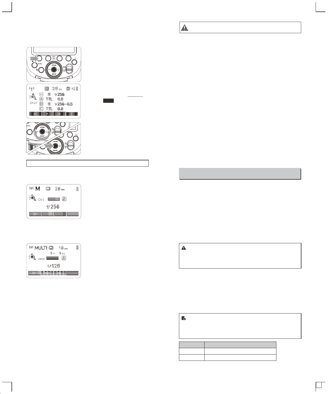
7. M: Wireless Flash Shooting with Manual Flash
This describes wireless (multiple shooting) using manual flash. You
can shoot with a different flash output setting for each receiver unit
(firing group). Set all parameters on the transmitter unit.
Setting the flash mode to
1 <M>.
Taking the picture.
3
Setting <M> Flash Mode
You can directly operate the receiver unit to manually set the manual
flash or stroboscopic flash.
Setting the receiver unit.
1
Setting flash mode to <M>.
2
● Press <MODE> button so
that <M> is displayed.
● Set the manual flash
output. (Page 41)
Setting flash
2 output.1/2/3/4<M/A/B/C>
● Press Function Button 3
< >. Turn the Select
Dial to set the flash output
of the groups. Press Set
Button to confirm.
Gr
● Each group fires at the set
flash ratio.
8. Multi: Wireless Flash Shooting with Manual Flash
Setting <Multi> stroboscopic
flash.
● Press <MODE> button so that
<Multi> is displayed.
● Setting the stroboscopic flash.
(Page 42)
Other Applications
Sync Triggering
The Sync Cord Jack is a Φ2.5mm plug. Insert a trigger plug here
and the flash will be fired synchronously with the camera shutter.
Modeling Flash
If the camera has a depth-of-field preview button, pressing it will fire
the flash continuously for 1 second. This is called modeling flash.
It enables you to see the shadow effects on the subject and the
lighting balance. You can fire the modeling flash during wireless or
normal flash shooting.
● To avoid overheating and deteriorating the flash head, do
not fire the modeling flash for more than 10 consecutive
times. If you fire the modeling flash 10 consecutive times,
allow at least 10 minutes’ break for the camera flash.
Auto Focus Assist Beam
In poorly-lit or low-contrast shooting environments, the built-in auto
focus assist beam will automatically light on to make it easier for
autofocus. The beam will light up only when autofocus is difficult
and get out as soon as the autofocus becomes correct.
If you want to turn off the auto focus assist beam, set the “AF” to
“OFF” on the C.Fn settings.
● If you find the auto focus assist beam does not light up, this
is because the camera has got a correct autofocus.
● Camera models that support auto focus assist beam:
X-PRO2, X-T20, X-T2, X-T1, GFX50S, GFX50R, X-T30
Position
Center
Periphery
Effective Range
0.6~10m / 2.0~32.8 feet
0.6~5m / 2.0~16.4 feet
- 49 - - 50 -
RX
1. Disturbed by the 2.4G signal in outer environment (e.g.
wireless base station, 2.4G wifi router, Bluetooth, etc.)
→ To adjust the channel CH setting on the flash trigger (add 10+
channels) and use the channel which is not disturbed. Or turn off the
other 2.4G equipment in working.
2. Please make sure that whether the flash has finished its
recycle or caught up with the continuous shooting speed or
not(the flash ready indicator is lighten) and the flash is not
under the state of over-heat protection or other abnormal
situation.
→ Please downgrade the flash power output. If the flash is in TTL
mode, please try to change it to M mode(a preflash is needed in TTL
mode).
3. Whether the distance between the flash trigger and the flash
is too close or not
→ Please turn on the “close distance wireless mode” on the flash
trigger (<0.5m):
X2 & X1 series: press the test button and hold on, then turning
it on until the flash ready indicator blinks for 2 times.
XPro series: Set the C.Fn-DIST to 0-30m.
4. Whether the flash trigger and the receiver end equipment are
in the low battery states or not
→Please replace the battery(the flash trigger is recommended to
use 1.5V disposable alkaline battery).
The Reason & Solution of Not Triggering in Godox 2.4G Wireless
9. TTL/M Shortcut Function
1. In non TTL wireless mode, push the TTL/M shortcut can
quickly change to flash mode.
2. When switching TTL to M manual mode, there is TCM switch
by default.
RX
10. Lock Function
In any interface, long press the MENU button for 2 seconds to
lock or unlock the operation function of interface. LOCKED will
be displayed when being locked.
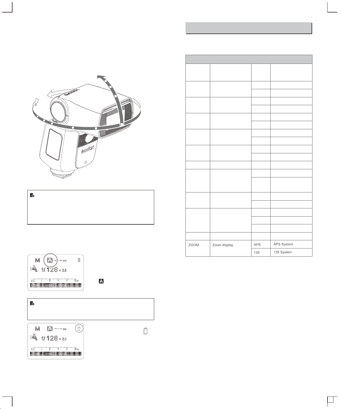
Bounce Flash
By pointing the flash head toward a wall or ceiling, the flash will
bounce off the surface before illuminating the subject. This can
soften shadows behind the subject for a more natural-looking shot.
This is called bounce flash.
To set the bounce direction, hold the flash head and turn it to a
satisfying angle.
● If the wall or ceiling is too far away, the bounced flash might
be too weak and result in underexposure.
● The wall or ceiling should be a plain, white color for high
reflectance. If the bounce surface is not white, a color cast
may appear in the picture.
ZOOM: Setting the Flash Coverage
The flash coverage can be set automatically or manually. It can be
set to match the lens focal length from 20mm to 200mm.
In Manual Zoom mode, press the
<ZOOM> button.
● Turn the Select Dial to change
the flash coverage.
● If < > is displayed, the flash
coverage will be set
automatically.
If you set the flash coverage manually, make sure it covers
the lens focal length so that the picture will not have a dark
periphery.
Low Battery Warning
If the battery power is low, < >
will appear and blink on the LCD
panel. Please replace the battery
immediately.
C.Fn: Setting Custom Functions
The following table lists the available and unavailable custom
functions of this flash.
m/ft
BEEP
LIGHT
LCD
ID
m
ft
ON
OFF
12sec
OFF
ON
-3~+3
OFF
01-99
Distance indicator
Beeper
Backlighting time
LCD contrast ratio
Wireless ID
C.Fn Custom Functions
Custom
Function
Signs
Function
Setting
No.
Settings & Description
m
feet
AF
ON
OFF
AF-assist beam
ON
OFF
RX STBY
60min
30min
Receiver auto power
off timer
60min
30min
ON
OFF
Off in 12 sec.
Always off
Always lighting
7 levels
Off
Choose any figure
from 01-99
1. Press<MENU> Button until C.Fn menu is displayed. The “Ver
x.x” in the top-right corner refers to the software version.
2. Select the Custom Function No.
● Turn the Select Dial to select the Custom Function No.
3. Change the Setting.
● Press Set Button and the Setting No. blinks.
● Turn the Select Dial to set the desired number. Pressing Set
Button will confirm the settings.
● After you set the Custom Function and press <MENU> button,
the camera will be ready to shoot.
4. In the C.Fn states, long press the “Clear”button for 2 seconds
until “OK”is displayed on the panel, which means the values in
C.Fn can be reset.
STBY
ON
OFF
Auto sleep setting
ON
OFF
SCAN
OFF
START
Scan the spare channel
OFF
Start to find the spare
channel
CH
01-32
Channel setting
Choose channels
from 01-32
- 51 - - 52 -
330°
-7-120°
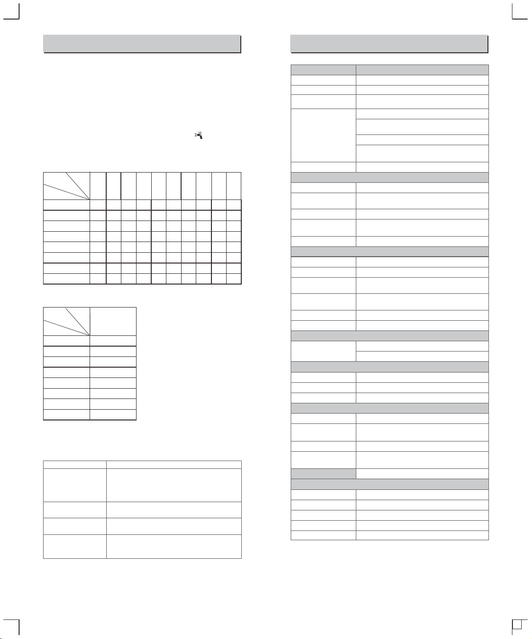
Protection Function
1. Over-Temperature Protection
● To avoid overheating and deteriorating the flash head, there is
over-temperature protection in the system. When continuously
firing for many times, the inner over-temperature protection
function may be activated and make the recycling time slow.
If this occurs, allow a rest time of about 10 minutes, and the flash
unit will then return to normal.
● When the over-temperature protection is started, is shown on
the LCD display.
Number of flashes that will activate over-temperature
protection:
2. Other Protections
The system provides real-time protection to secure the device and
your safety. The following lists prompts for your reference:
Number of flashes that will activate over-temperature
protection in high-speed sync triggering mode:
Meaning
A failure occurs on the recycling system so that the
flash cannot fire.
Please restart the flash unit. If the problem still exists,
please send this product to a maintenance center.
The system gets excessive heat. Please allow a rest
time of 10 minutes.
The voltage on two outlets of the flash tube is too high.
Please send this product to a maintenance center.
There are some errors occurred during the upgrading
process. Please using the correct firmware upgrade
method.
Prompts on LCD Panel
E1
E2
E3
E9
Technical Data
- 53 -
- 54 -
Power
Output Level
Number
of Flashes
ZOOM
1/1
1/2
1/4
1/8
1/16
1/32
1/64
1/128
40
50
100
200
300
500
1000
2000
50
60
100
200
300
500
1000
2000
50
60
100
200
300
500
1000
2000
60
75
100
200
300
500
1000
2000
60
75
120
200
300
500
1000
2000
75
100
150
200
300
500
1000
2000
75
100
150
200
300
500
1000
2000
80
100
150
200
300
500
1000
2000
80
100
150
200
300
500
1000
2000
80
100
150
200
300
500
1000
2000
20 24 28 35 50 70 80 105 135 200
1/1
1/2
1/4
1/8
1/16
1/32
1/64
1/128
30
30
34
40
50
50
60
60
20 - 200
Power
Output Level
Number
of Flashes
ZOOM
(mm)
(mm)
V860IIIF
FUJIFILM cameras (TTL autoflash)
76Ws
20 to 200mm
• Auto zoom (Flash coverage set automatically
to match the lens focal length and image size)
• Manual zoom
• Swinging/tilting flash head (bounce flash): 0 to 330°
horizontally and -7° to 120° vertically
1/300 to 1/20000 seconds
TTL autoflash and manual flash
Manual. FEB: ±3 stops in 1/3 stop increments
(Manual FEC and FEB can be combined.)
With <FEL> button or < * > button
High-speed sync (up to 1/8000 seconds),
first-curtain sync, and second-curtain sync
Provided (up to 90 times, 100Hz)
Transmitter, Receiver, Off
100m
32 (1~32)
Fired with camera’s depth-of-field preview button
Center: 0.6~10m / 2.0~32.8 feet
Periphery: 0.6~5m / 2.0~16.4 feet
Model
Compatible Cameras
Power
(1/1 output)
Flash Focal Length
Coverage
Flash Duration
• Exposure Control
Exposure control system
Flash exposure
compensation (FEC)
FE lock
Sync mode
Multi flash
• Wireless Flash
Wireless flash function
Controllable
Receiver groups
Transmission range
(approx.)
Channels
Modeling flash
• Auto Focus Assist Beam
Effective range (approx.)
ID
01~99
2W
• LED Modeling Lamp
Power
5300K±200K
Color Temperature
7.2V/2600mAh Li-ion battery
Approx 1.5 seconds. Green LED indicator will light up
when the flash is ready.
Approx. 480
Power off automatically after approx. 90 seconds
of idle operation. (60 minutes if set as Receiver)
Hotshoe, 2.5mm sync line
195*75*59 mm
410g
530g
• Power Supply
Power source
Recycle time
Full power flashes
Power saving
• Sync Triggering Mode
• Dimensions
W x H x D
Weight without battery
Weight with battery
M,A,B,C
A, B, C, D, E (D/E group can be controlled
by X series flash trigger)
Transmitter groups
Guide No.(1/1 output,
200mm)
GN≈60 (m ISO100)
2413.0MHz-2465.0MHz
5dbm
2.4G Frequency Range
Max. Transmitting Power
Troubleshooting
If there is a problem, refer to this Troubleshooting Guide.
The Camera Flash does not fire.
● The camera flash is not attached securely to the camera.
→Attach the camera’s mounting foot securely to the camera.
● The electrical contacts of the Camera Flash and camera are dirty.
→Clean the contacts.
● < > or < > is not displayed in the view finder of camera.
→Wait until the flash is fully recycled and the flash ready indicator
lights up.
→If the flash ready indicator lights up, but < > or < > is not
displayed in the view finder, check whether this flash unit is
securely attached to the camera hotshoe.
→If the flash ready indicator does not light up after a long wait,
check whether the battery power is enough. If the battery power
is low, < > will appear and blink on the LCD panel. Please
replace the battery immediately.
The power turns off by itself.
● After 90 seconds of idle operation, auto power off took effect if the
flash is set as transmitter.
→Press the shutter button halfway or press any flash button to
wake up.
● After 60 minutes (or 30 minutes) of idle operation, the flash unit
will enter sleep mode if it is set as receiver.
→Press any flash button to wake up.
Auto zoom does not work.
● The camera flash is not attached securely to the camera.
→Attach the camera flash’s mounting foot to the camera.
The flash exposure is underexposed or overexposed.
● You used high-speed sync.
→With high-speed sync, the effective flash range will be shorter.
Make sure the subject is within the effective flash range
displayed.
● You used Manual Flash mode.
→Set the flash mode to TTL or modify the flash output.
Photos have dark corners or only parts of the target subject
are illuminated.
● The focal length of lens exceeds the flash coverage.
→Check the flash coverage you set. This flash unit has the flash
coverage between 20 and 200mm, which fits medium-format
cameras.
Firmware Upgrade
● The USB port is a Type-C USB socket. Type-C USB connection
line is applicable.
● As the firmware upgrade needs the support of Godox G3
software, please download and install the "Godox G3 firmware
upgrade software" before upgrading. Then, choose the related
firmware file.
● As the product needs to do firmware upgrade, please refer to
instruction manual of the newest electric version as final.
Compatible Camera Models
● Shut down the device immediately should abnormal operation be
detected.
● Avoid sudden impacts and the product should be dedusted
regularly.
● It is normal for the flash tube to be warm when in use. Avoid
continuous flashes if unnecessary.
● Maintenance of the flash must be performed by our authorized
maintenance department which can provide original accessories.
● This product, except consumables e.g. flash tube, is supported
with a one-year warranty.
● Unauthorized service will void the warranty.
● If the product had failures or was wetted, do not use it until it is
repaired by professionals.
● Changes made to the specifications or designs may not be
reflected in this manual.
Maintenance
- 55 -
- 56 -
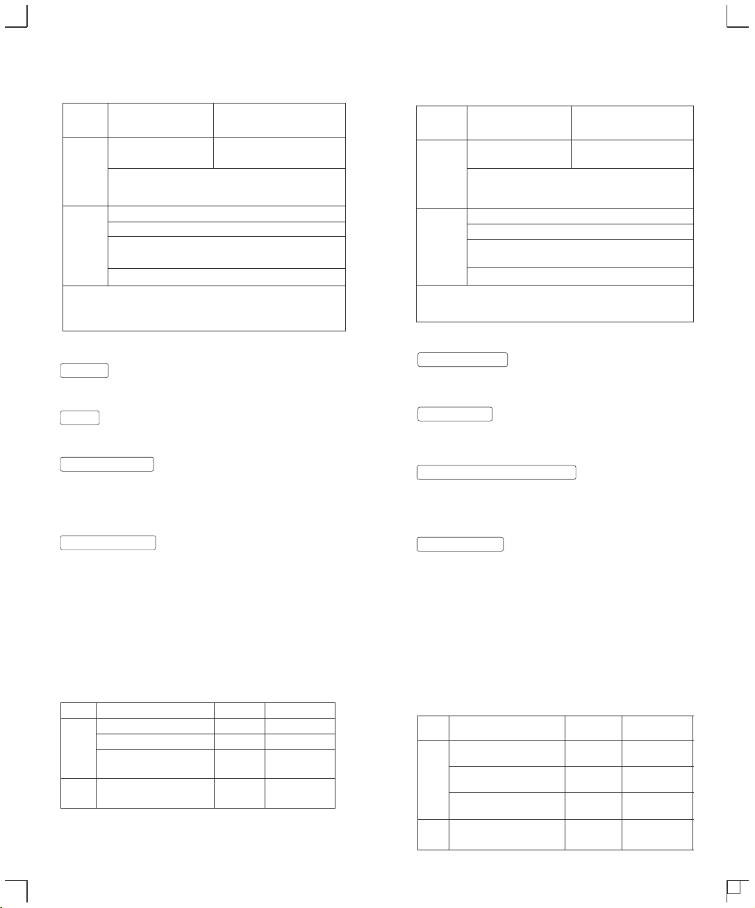
,X-T30
()
()
()
12
3
12
0755-29609320-8062
Warranty
Dear customers, as this warranty card is an important certificate to apply for
our maintenance service, please fill in the following form in coordination with
the seller and safe-keep it. Thank you!
Note: This form shall be sealed by the seller.
Applicable Products
The document applies to the products listed on the Product Maintenance lnformation (see
below for further information). Other products or accessories (e.g. promotional items,
giveaways and additional accessories attached, etc.) are not included in this warranty
scope.
Warranty Period
The warranty period of products and accessories is implemented according to the relevant
Product Maintenance lnformation. The warranty period is calculated from the day(purchase
date) when the product is bought for the first time, And the purchase date is considered as
the date registered on the warranty card when buying the product.
Product
Information
Model Product Code Number
Name Contact Number
Address
Customer
Information
Seller
Information
Note:
Name
Contact Number
Address
Date of Sale
If maintenance service is needed, you can directly contact the product distributor or
authorized service institutions. You can also contact the Godox after-sale service call and
we will offer you service. When applying for maintenance service, you should provide valid
warranty card. If you cannot provide valid warranty card, we may offer you maintenance
service once confirmed that the product or accessory is involved in the maintenance scope,
but that shall not be considered as our obligation.
The guarantee and service offered by this document are not applicable in the following
cases: . The product or accessory has expired its warranty period; . Breakage or
damage caused by inappropriate usage, maintenance or preservation, such as improper
packing, improper usage, improper plugging in/out external equipment, falling off or
squeezing by external force, contacting or exposing to the improper temperature, solvent,
acid, base, flooding and damp environments, etc; . Breakage or damage caused by non-
authorized institution or staff in the process of installation, maintenance, alternation,
addition and detachment; . The original identifying information of product or accessory is
modified, alternated, or removed; . No valid warranty card; . Breakage or damage
caused by using illegally authorized, nonstandard or non-public released software; .
Breakage or damage caused by force majeure or accident; . Breakage or damage that
could not be attributed to the product itself. Once met these situations above, you should
seek solutions from the related responsible parties and Godox assumes no responsibility.
The damage caused by parts, accessories and software that beyond the warranty period or
scope is not included in our maintenance scope. The normal discoloration, abrasion and
consumption are not the breakage within the maintenance scope.
How to Get the Maintenance Service
Inapplicable Cases
Maintenance and Service Support Information
The warranty period and service types of products are implemented according to the
following Product Maintenance Information:
Product
Type
Parts
Other
Items
Name
Circuit Board
Battery
Electrical parts e.g.battery
charger, power cord, sync cable,
etc.
Flash tube, modeling lamp, lamp
body, lamp cover, lockingdevice,
package, etc.
Maintenance
Period(month)
12
3
12
No
Warranty Service
Type
Customer sends
the product to
designated site
Without warranty
Customer sends
the product to
designated site
Customer sends
the product to
designated site
Godox After-sale Service Call
0755-29609320-8062

This device complies with part 15 of the FCC Rules. Operation is
subject to the following two conditions: (1) This device may not
cause harmful interference, and (2) this device must accept any
interference received, including interference that may cause
undesired operation.
Any Changes or modifications not expressly approved by the party
responsible for compliance could void the user's authority to operate
the equipment.
Note: This equipment has been tested and found to comply with the
limits for a Class B digital device, pursuant to part 15 of the FCC
Rules. These limits are designed to provide reasonable protection
against harmful interference in a residential installation. This
equipment generates uses and can radiate radio frequency energy
and, if not installed and used in accordance with the instructions,
may cause harmful interference to radio communications. However,
there is no guarantee that interference will not occur in a particular
installation. If this equipment does cause harmful interference to
radio or television reception, which can be determined by turning
the equipment off and on, the user is encouraged to try to correct
the interference by one or more of the following measures:
- Reorient or relocate the receiving antenna.
- Increase the separation between the equipment and receiver.
- Connect the equipment into an outlet on a circuit different from that
to which the
receiver is connected.
- Consult the dealer or an experienced radio/TV technician for help.
The device has been evaluated to meet general RF exposure
requirement.
The device can be used in portable exposure condition without
restriction.
FCC Statement
Declaration of Conformity:
GODOX Photo Equipment Co,Ltd. hereby declares that the This
equipment are in compliance with the essential requirements and
other relevant provisions of EU Directive 2014/53/EU. They are
allowed to be used in all EU member states.
For more information of DoC, Please click this web
link:http://www.godox.com/DOC/Godox_V860III_Series_DOC.pdf.