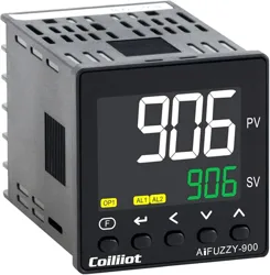
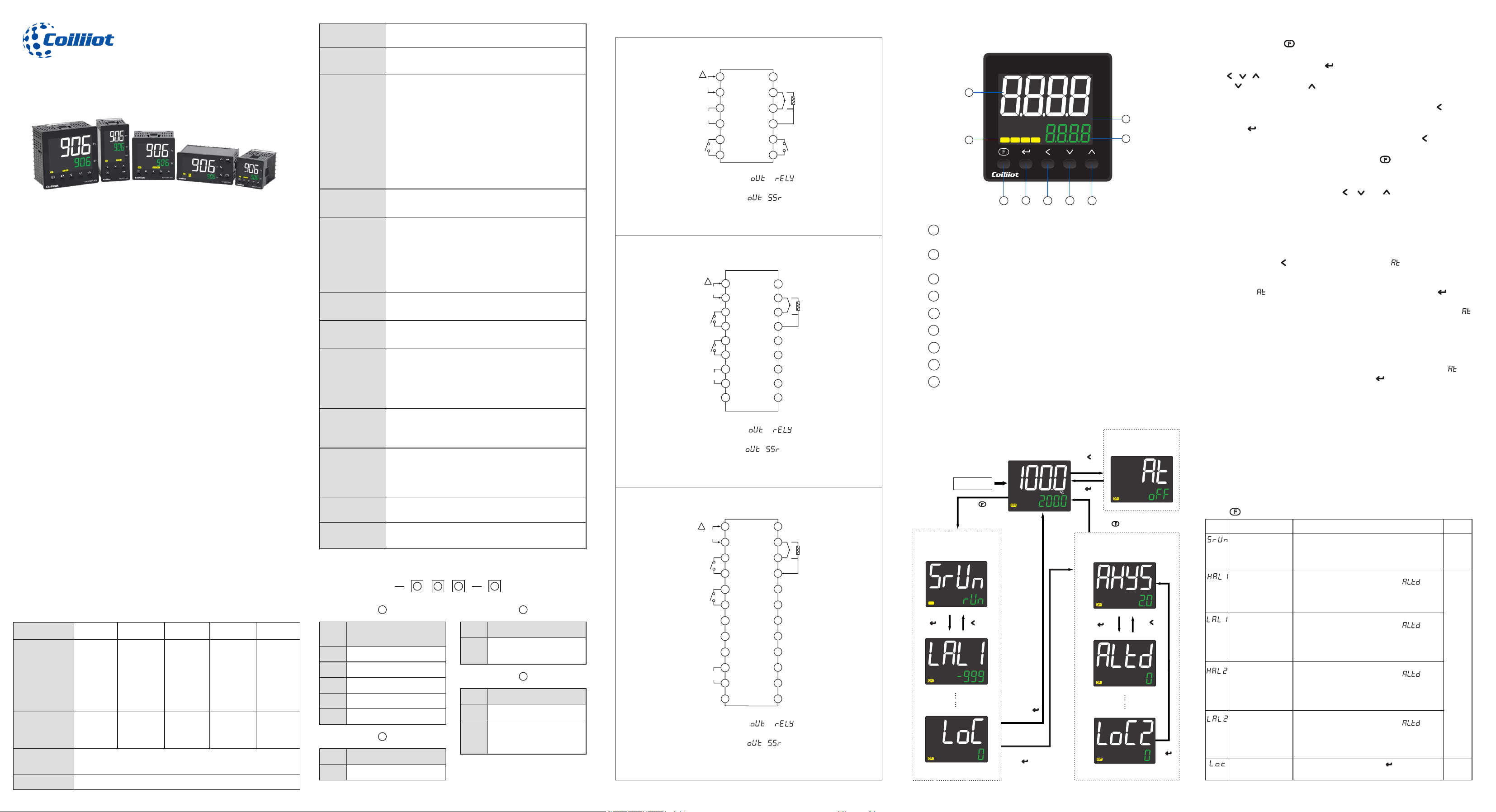
(User Manual)
Economical PID Temperature Controller
For General Use (AiFUZZY-906)
1.Main features
– The PID controller provides dual output options: Relay and SSR (Solid-State
-Relay). Users can configure the desired output type—either Relay or SSR—
via the system parameter settings.
– The color LCD display features white PV text for easy readability from a
distance. The side-illuminated back-light, combined with the advanced LCD
screen, ensures a soft and clear display.
– Equipped with a patented plastic handle and a waterproof button, the device
features built-in waterproof sealing rings on both the button and the panel.
The entire panel is rated IP65, ensuring reliable protection against water and
dust ingress.
– Economically engineered for user-friendly operation, this device is
specifically tailored to deliver practical and reliable temperature control.
– Supports standard thermocouple (TC) and resistance temperature
detector (RTD) input types, selectable through software parameter settings.
– Delivers a measurement accuracy of ±0.25%. Digital correction and
self-calibration technology effectively eliminate errors caused by
temperature drift and time drift, ensuring long-term precision and stability.
– Features an advanced "FUZZY + PID" AI control algorithm that effectively
prevents overshoot. Includes auto-tuning (AT) and self-adaptation functions
for optimal performance and ease of use.
– Supports up to two alarm outputs. When the control output is configured
as SSR, the Relay output can be utilized as the second alarm output (Al2),
providing enhanced flexibility in alarm management.
– The temperature unit—°C or °F—can be easily selected through software
parameter settings to suit user preferences or regional requirements.
– Equipped with a high-efficiency, high-reliability switching power supply
that supports a wide global voltage range of AC 100–240V, ensuring stable
performance in various environments.
– Designed to meet stringent electromagnetic compatibility (EMC)
standards, the device delivers strong anti-jamming performance for
reliable operation in harsh industrial environments.
2.Technical Specification
Panel type
G
D
A
E
F
Panel Size
(Width *
Height)
48*48
mm
(1.89*1.
89 inch
or 1/16
DIN)
72*72
mm
(2.83*2.
83 inch
or 3/16
DIN)
96*96
mm
(3.78*3.
78 inch
or1/4
DIN)
48*96
mm
(1.89*3.
78 inch
or 1/8
DIN)
96*48
mm
(3.62*1.
77 inch
or 1/8
DIN)
Drill Gap
(Width *
Height)
45*45
mm
68*68
mm
92*92
mm
45*92
mm
92*45
mm
Power supply
AC100~240V 50/60Hz (or DC12~24V needs
customization)
Voltage Range
85%~ 110%of the rated power voltage
Power
consumption
Less than 3W
Display
LCD display (white for PV, green for SV, light
orange for indicator)
Measurement
Range
(Input)
K: (-50~1300°C / -58~2372°F)
E: (0~800°C / 32~1472°F)
J: (0~1000°C / 32~1832°F)
N: (0~1300°C / 32~2372°F)
Pt100: (-200~600°C / -328~1112°F)
Decimal Point
Positioning
0(None), 0.0 (adjustable based on parameters)
Measurement
accuracy
Achieves grade 0.25 accuracy when using thermal
resistance (RTD) or thermocouple inputs, with
cold-junction compensation provided by copper
resistance or a reference freezing point.
When cold-junction compensation is handled by
the instrument’s internal components,
thermocouple input accuracy is ±0.25% FS ± 2.0°C.
Sampling
Frequency
80ms; when digital filtering is set to INF=0,
response time is 0.5 seconds
Control Method
ON/OFF control, AI FUZZY algorithm, PV tracking
and SV value setting
Contact
output
Relay+SSR Dual type output
Relay:5A/250VAC Resistive Load, 5A/30VDC
resistive load
SSR:12VDC/50mA
(Drive external solid state relay)
Electromagneti
c
Compatibility
IEC61000-4-4( ) at electrical fast transient burst
4KV/5KHz; IEC61000-4-5(surge ) at 4KVimmunity
Isolation
Voltage
Input/output, power output/control module:
≥2300VDC; signal terminals between phase-to-
phase signals ≥600VDC
Operating
Temperature
-10~60°C (14~140°F) (no condensation, no ice
formation), humidity: 25~85%RH
Storage
temperature
25~70°C (-13~158°F) (no condensation, no ice
formation), humidity: 25~85%RH
AiFUZZY-906-A,E,F
Relay
OUT/AL2
250VAC
5A max
SSR OUT
12VDC
50mA max
AL1
250AC
5A max
1
2
3
4
5
6
7
8
9
10
11
12
13
14
15
16
17
18
19
20
21
22
23
24
POWER:
!
+
-
A
TC
RTD
B
B
+
-
AiFUZZY-906-D
Relay
OUT/AL2
250VAC
5A max
SSR OUT
12VDC
50mA max
AL1
250AC
5A max
1
2
3
4
5
6
7
8
9
10
11
12
13
14
15
16
17
18
POWER:
!
+
-
TC
A
RTD
B
B
+
-
1
2
3
4
5
6
POWER:
Relay
OUT /AL2
250VAC
5A max
A
TC
RTD
B
B
+
SSR OUT
12VDC
50mA max
+
-
-
AL1
250AC
5A max
!
7
8
9
10
11
12
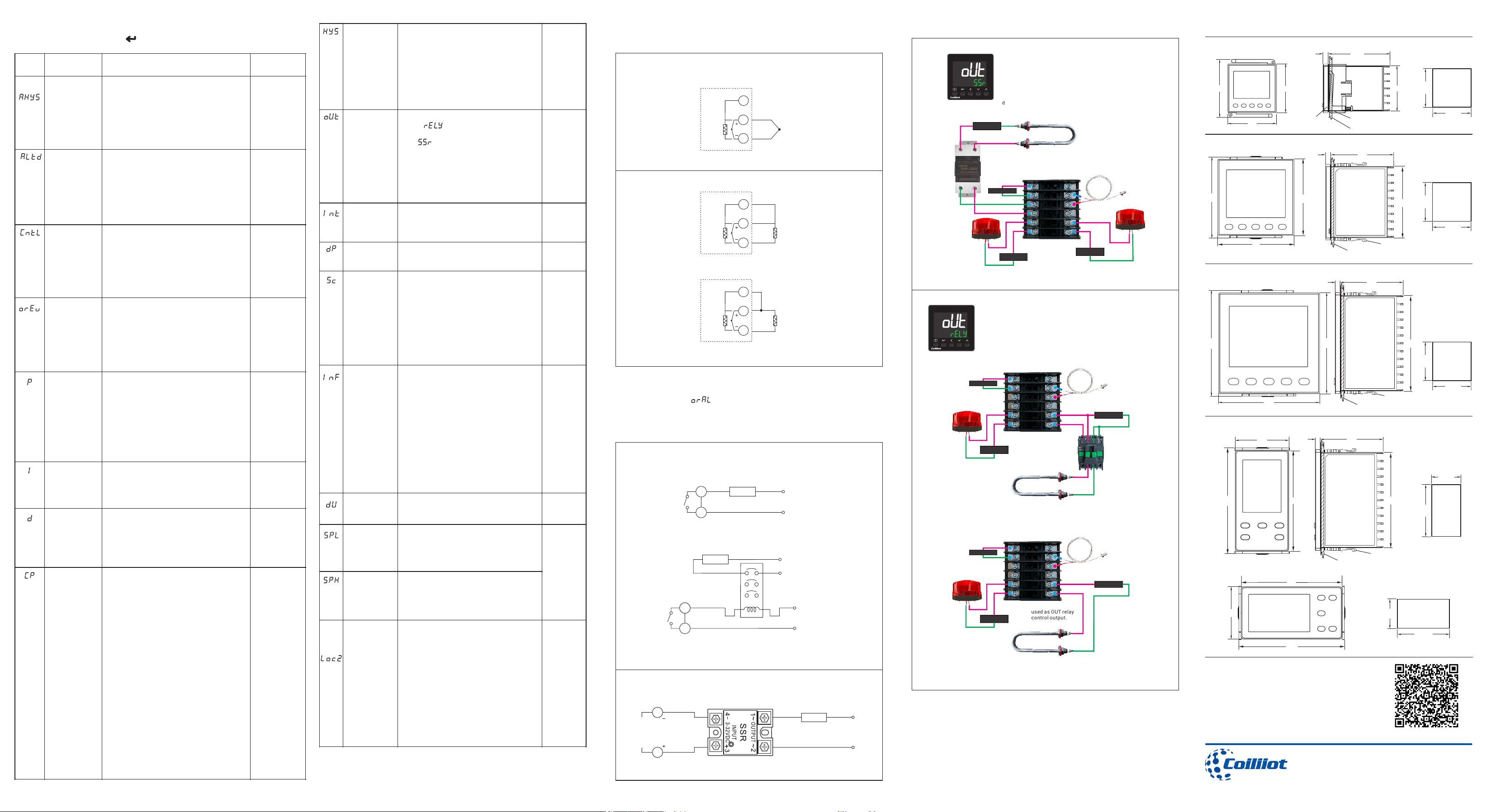
4.Wiring diagram
5.Front Panel Description
Parameter key :Entry / exit parameter settings
Data increase key(also serves as stop key)
Data decrease key(also serves as run key)
PV first display window
(displays measured values, parameter names, etc.).
SV second display window
(displays setpoint values, parameter values, etc.).
Temperature unit
Output indicators:OP1,AL1,AL2 indicators
Data shift key(start auto tuning)
1
2
3
4
5
6
7
8
9
Return key: confirm and switch to the next parameter
2
3
4
AiFUZZY-906
1
3.Ordering Code Definition
Code
Dimensions
(width × height)
G
48×48mm (1/16 DIN)
D
72×72mm (3/16 DIN)
A
96×96mm (1/4 DIN)
E
48×96mm (1/8 DIN)
F
96×48mm(1/8 DIN)
2
3
4
1
Code
Power supply
Blank
AC100~240V
D
DC12~24V (Needs
customization order
from official website)
Code
ALM larm (A )
R1
AL1(Alarm relay output)
Code
OUT (control output)
Q5
Relay+SSR
(Dual type output)
6.Display the status and basic operation
AiFUZZY-900
PV
SV
%
MAN PAR
ºFºC
OP1
AU1
AL1 AL2
1
4
5
6
7 8
9
2
3
Set AT to On
to start self-tuning
for 2 seconds
Initial display
key for 2 seconds
for 2 seconds
Set lock to 800, then
press key
If lock ≠800,
press the
key
POWER ON
ºC
Parameter 1
Parameter 2
2 seconds
Key
The last parameter
Other
parameters
Operation parameters
OP1
System parameters
for 2 seconds
key
Parameter 1
Parameter 2
The last parameter
Other
parameters
Press for2 seconds to enter the operation parameter settings
7.Parameter list and function
7.1 Operation parameters
Code
Name
Description
Range
Operating Status
Run: The instrument is in normal operating control
status.
Stop: The instrument is in a stopped control output
status, with the SV window flashing.
(Default
valuerun)
Alarm_1 max alarm
value
“HAL1" refers to the absolute value alarm or
deviation value alarm, defined by the " "
parameter. When the value is set to the maximum
(3200), this function will be disabled.
-999 to
3200(Fa
ctory
default
values:
HAL1
and
HAL2
are set
to 3200,
LAL1
and
LAL2 are
set to -
999)
Alarm_1 min alarm
value
“LAL1" refers to the absolute value alarm or
deviation value alarm, defined by the " "
parameter. When the value is set to the minimum (-
999), this function will be disabled.
Alarm_2 max alarm
value
“HAL2" refers to the absolute value alarm or
deviation value alarm, defined by the " "
parameter. When the value is set to the maximum
(3200), this function will be disabled.
Alarm_2 min alarm
value
“LAL2" refers to the absolute value alarm or
deviation value alarm, defined by the " "
parameter. When the value is set to the minimum (-
999), this function will be disabled.
System Parameter
Lock
Set Lock to 800, then press the key to enter the
system parameters.
Setting the given value
Auto-Tuning for Optimal PID Control
System parameter setting
In the initial display:
•Press and hold the key for about 2 seconds to enter the parameter
setting mode.
•If lock is set to 800, press the key to access the system parameters.
•Use , , to directly modify parameter values.
•Press to decrease and to increase values. Holding the keys enables
faster adjustments.
•To navigate directly to a specific digit for editing, press the key, then
adjust as needed.
•Press the key to save changes and move to the next parameter.
•To return to the previous parameter, press and hold the key for over
2 seconds.
•Exit to the basic display state by holding the key for 2 seconds.
To enable optimal PID control parameters using the auto-tuning feature,
follow the steps below for precise temperature control:
1. Initiate Auto-Tuning
Press and hold the key for 2 seconds until the " " parameter appears on
the display panel.
2. Activate Auto-Tuning
Change the " " parameter from "OFF" to "ON", then press the key to
confirm.
The instrument will start the auto-tuning process. During this time, " " will
flash on the main display.
3. Process Overview
After two ON-OFF oscillation cycles, the instrument will automatically
calculate and apply the optimal PID parameters.
4. Canceling Auto-Tuning (if needed)
If you need to stop auto-tuning before it completes, change the " "
parameter from "ON" to "OFF", and press the button to confirm.
5. Tips for Best Results
* Set the target value (SV) to a commonly used or median value before
starting auto-tuning.
* For systems with strong insulation (e.g., furnaces), set the target value to
the highest temperature typically used.
* Auto-tuning results may vary and often require a stabilization period—
usually equal to the tuning duration—for optimal performance.
Important:
Do not operate the controller or interrupt the power supply during the auto-
tuning process.
AiFUZZY-906-G
Press
key
Press
key
Press
Press
key
Press
Press
key
Press
Press
key
Press
key
In the basic display state: Use the , , or keys to modify
the given value directly.
When output mode is set to Relay( = ), terminals ⑪ and ⑫
function as control outputs, providing relay contact output.
When output mode is set to SSR ( = )is selected, terminals
③ and ④ serve as control outputs, delivering SSR drive voltage. In
this mode, terminals ⑪ and ⑫ can be configured as AL2 alarm relay
outputs.
When output mode is set to Relay( = ), terminals ⑤ and ⑥
function as control outputs, providing relay contact output.
When output mode is set to SSR ( = )is selected, terminals
⑦ and ⑧ serve as control outputs, delivering SSR drive voltage. In
this mode, terminals ⑤ and ⑥ can be configured as AL2 alarm relay
outputs.
When output mode is set to Relay( = ), terminals ⑤ and ⑥
function as control outputs, providing relay contact output.
When output mode is set to SSR ( = )is selected, terminals
⑩ and ⑪ serve as control outputs, delivering SSR drive voltage. In
this mode, terminals ⑤ and ⑥ can be configured as AL2 alarm relay
outputs.
Control
hysteresis
HYS (Hysteresis) is used in ON-OFF
control to prevent the relay from
frequently switching on and off. For a
reverse acting (heating) system: When
PV > SV, the output turns off. When PV <
SV - HYS, the output turns on. For a
direct acting (cooling) system:When PV
< SV, the output turns off. When PV > SV
+ HYS, the output turns on.
0~
200.0
(default
value 2.0)
(OUT)
Control
output
Output Types
Relay ( ): Relay contact signal
output
SSR( ): Solid-state relay (SSR) drive
output
Note: When output is set to SSR, the relay
output originally used for control can be
reassigned as the AL2 alarm output,
enabling the use of two independent
alarm outputs.
(Default
value: Relay)
Input Signal
Selection of input Types for
thermocouples or RTD:
K,E,J,N,Pt (Pt100)
default
value: K
Decimal
point
0 :no decimal.
0.0:one decimal place.
default
value: 0.0
Input
correction
SC is used to adjust the input signal to
compensate for errors caused by the
transducer, input signal, or automatic
cold junction compensation of the
thermocouple.
PV after compensation = PV before
compensation + SC.
It is generally set to 0. An incorrect
setting may result in inaccurate
measurements.
-199.9~
+400.0
(default
value:
0.0)
PV
input filter
The value of InF determines the ability
to filter noise from the input signal.
- When a large value is set, the
measurement input stabilizes, but the
response speed slows down. Typically,
it can be set between 1 and 3.
- If significant interference is present,
gradually increasing the InF value can
help reduce momentary fluctuations in
the measured value, keeping them
within 2 to 5 units.
- During metrological verification of the
instrument, set InF to 0 or 1 to shorten
the response time.
0~40
(default
value:
2)
Temperature
unit
°C:celsius
°F:fahenheit
default
value: °C
Min of SV
Minimum value that SV is allowed to be.
-999~
3200
( default
value:
SPL is
-99,
SPH is
999)
Max of SV
Maximum value that SV is allowed to be.
Password
lock2
Parameter Lock Function (LOC2 Setting)
LOC2 = 0: Unlocked – No locking function
enabled.
LOC2 = 1: Locks the AT (Auto-Tuning)
parameter – AT cannot be modified.
LOC2 = 2: Locks field parameters – Field
parameters cannot be modified.
LOC2 = 3: Locks SV (Set Value) – SV
cannot be adjusted.
LOC2 = 4: Fully locked – AT parameter,
field parameters, and SV setting cannot
be modified.
0~4
(Default
value 0)
Made in China
Official Website: https://coiliiot.com
Email: support@coiliiot.com
48
58
48
78
72
72
100
96
96
96
100
48
48
100 96
68
92
60
4.7
48
60
4.7
65.2
4.7
45
AiFUZZY-906-G
45
+0.6
-0
92
48
60
4.7
AiFUZZY-906-D
AiFUZZY-906-A
AiFUZZY-906-E ,F
92
+0.6
-0
45
+0.6
-0
92
+0.6
-0
92
+0.6
-0
92
+0.6
-0
68
+0.6
-0
68
+0.6
-0
45
+0.6
-0
45
+0.6
-0
Panel thickness 1~5mm
Mounting Adapter(Accessory)
Waterproof
Packing
(Accessory)
Mounting Adapter(Accessory)
Panel thickness 1~5mm
Mounting Adapter(Accessory)
Mounting Adapter(Accessory)
Panel thickness 1~5mm
Panel thickness 1~5mm
Drill Gap
Drill Gap
10.Dimensions(in mm) and installation instructions
Relay
SSR
8. Wiring for Common Applications
8.1 Wiring of the inputs
Thermocouple
RTD
Pt
B
B
A
TC
Input
Pt
B
B
A
RTD
Input
Three-wire
RTD
Pt
B
B
A
Two-wire
RTD
RTD
Input
*If there is an input wiring error, sensor damage, input over-range, or a
mismatch between the input setting and the selected sensor type, the
display will flash a “ ” warning. Once the issue is resolved, the PV
(process value) display will return to normal operation.
8.2 Wiring of the outputs
OUT
Load
Max.5A
Resistive Load
Main power
Direct control load
Taking driving contactor to control 220V load as an example.
Load
Contactor
OUT
12V/50mA
Pulsed
Voltage
OUT
Load
Note:
1. The wiring diagram above uses the 48×48mm (1/16 DIN) panel
temperature controller as an example. Terminal numbering may vary
for other panel sizes, but the wiring logic remains the same—please
refer the respective terminal numbers accordingly.
2. The diagram illustrates input wiring for K, E, J, and N-type thermocouples.
For PT100 RTD input, please refer to this user manual accordingly.
3. Different input signal types require corresponding input parameter settings.
Refer to the manual for detailed configuration instructions.
POWER
POWER
OUT/AL2
OUT/AL2
AiF UZZY-900
PV
SV
%
MAN PA R
ºFº C
OP1
AU1
AL1 AL2
Setting output to Relay enables one relay control output and one alarm output.
OUT/AL2 port will be
used as OUT relay
control output.
OUT/AL2 port will be
used as OUT relay
control output.
AC contactor
POWER
POWER
POWER
POWER
POWER
POWER
AL1
AL1
Direct control of the heating tube:
The heating tube must be within 5A
Max 5A Heating tube
Control high-current heating tubes through a AC contactor
9. Common wiring cases
Setting output to SSR enables one SSR drive control output and two
independent alarm outputs.
POWER
OUT
POWER
POWER
POWER
-
+
AL1
SSR
OUT/AL2
POWER
OUT/AL2 port will be used
as AL2 alarm relay output.
Electric heating tube
Ai FUZ ZY-9 00
PV
SV
%
MAN PA R
ºFº C
OP1
AU1
AL1 AL2
7.2 System parameter
Set Loc = 800, then press the key to enter the following system
parameters
For a more detailed operation manual, please scan this QR code to obtain it!
N
L
Main power
N
L
Main power
N
L
Main power
N
L
Code
Name
Description
Range
Alarm
Hysteresis
Also known as alarm hysteresis or dead
zone, this feature is used to prevent the
alarm relay from frequently activating at
the alarm threshold. It introduces a delay
between the alarm output turning ON and
OFF to ensure stable operation.
0~2000.0
(default
value: 2)
Alarm mode
ALtd=0: AL1 is the deviation value alarm,
and AL2 is the absolute value alarm.
ALtd=1: Both AL1 and AL2 are absolute
value alarms.
ALtd=2: Both AL1 and AL2 are deviation
value alarms.
0~2
(default
value:1)
Control mode
onoF: On-off control, suitable for
situations that do not require high
precision.
FPId: Advanced artificial intelligence
AiFUZZY (FUZZY+PID) control
(Recommended for use).
default
value: FPId
Direct/Revers
e Action
onr: Reverse acting. An increase in the
measured variable causes a decrease in
the output, such as in heating control.
ond: Direct acting. An increase in the
measured variable causes an increase in
the output, such as in cooling control.
default value:
onr
Proportional
band
The proportional band for FPID control is
expressed in the same units as the PV
value, rather than as a percentage of the
range. Generally, optimal P, I, D, and CP
values can be obtained through auto-
tuning. Alternatively, they can be
manually entered if the correct values are
already known.
1~3200
default
value: 25
Integral Time
The integral time for FPID control is
measured in seconds. When I=0, the
integral action is disabled.
1~9999
default
value:200
Derivative
Time
The derivative time for FPID control is
measured in 0.1-second units. When d=0,
the derivative action is disabled.
0~3200
(default
value: 50.0)
Control cycle
CP reflects the speed at which the
instrument operator adjusts the control.
The size of the CP affects the control
accuracy.
For SSR and SCR output control, a shorter
control cycle is preferred, typically
between 0.5 to 3.0 seconds. For relay
switch outputs, a cycle time of 15 to 40
seconds is generally used.
When the output relay switches, the CP is
limited to 3 seconds. The self-tuning (AT)
function will automatically adjust the CP
to the appropriate value, optimizing
control accuracy and prolonging the
mechanical switch life.
When the control mode is set to CntL =
onoF, the CP acts as the output
disconnect or power-on delay time.
0.2~
300.0
( default
value: Relay
output
is 15.0,
SSR output
is 2.0)
Drill Gap
Drill Gap
Drill Gap