

Control 01 and 02
Installation Guide

Table of contents
▪ Safety information. . . . . . . . . . . . . . . . . . . . . . . . . . . . . . . . . . . . . . . . . . . . . . . . . . . . . . . . . . . . . . . . 4
▪ General description . . . . . . . . . . . . . . . . . . . . . . . . . . . . . . . . . . . . . . . . . . . . . . . . . . . . . . . . . . . . . . 6
▪ Before you start . . . . . . . . . . . . . . . . . . . . . . . . . . . . . . . . . . . . . . . . . . . . . . . . . . . . . . . . . . . . . . . . . 8
▪ Mechanical installation and low fan noise . . . . . . . . . . . . . . . . . . . . . . . . . . . . . . . . . . . . . . . . . . . 9
▪ Network configuration . . . . . . . . . . . . . . . . . . . . . . . . . . . . . . . . . . . . . . . . . . . . . . . . . . . . . . . . 10
▪ Control software installation. . . . . . . . . . . . . . . . . . . . . . . . . . . . . . . . . . . . . . . . . . . . . . . . . . . . . . . . 11
▪ Installing the DADman remote control program . . . . . . . . . . . . . . . . . . . . . . . . . . . . . . . . . . . . . . 12
▪ Connect your Control 01 or 02 to DADman . . . . . . . . . . . . . . . . . . . . . . . . . . . . . . . . . . . . . . . . 13
▪ Assigning the IP address for the computer and the Control 01 and 02 . . . . . . . . . . . . . . . . . 14
▪ Installation of Thunder | Core driver for macOS . . . . . . . . . . . . . . . . . . . . . . . . . . . . . . . . . . . . . . 16
▪ Installation of Thunder | Core ASIO driver on Windows PC. . . . . . . . . . . . . . . . . . . . . . . . . . . . . . 17
▪ Operation. . . . . . . . . . . . . . . . . . . . . . . . . . . . . . . . . . . . . . . . . . . . . . . . . . . . . . . . . . . . . . . . . . . . . 18
▪ Front panel layout . . . . . . . . . . . . . . . . . . . . . . . . . . . . . . . . . . . . . . . . . . . . . . . . . . . . . . . . . . . 19
▪ Rear panel connections . . . . . . . . . . . . . . . . . . . . . . . . . . . . . . . . . . . . . . . . . . . . . . . . . . . . . . . 20
▪ Digital I/O and Network Connections . . . . . . . . . . . . . . . . . . . . . . . . . . . . . . . . . . . . . . . . . . . . . 21
▪ Dual MADI SFP I/O mini-module (optional) . . . . . . . . . . . . . . . . . . . . . . . . . . . . . . . . . . . . . . 21
▪ Dual Gigabit Ethernet RJ45 connectors . . . . . . . . . . . . . . . . . . . . . . . . . . . . . . . . . . . . . . . . 21
▪ Thunderbolt 3 connectors. . . . . . . . . . . . . . . . . . . . . . . . . . . . . . . . . . . . . . . . . . . . . . . . . . 22
▪ MADI connectors . . . . . . . . . . . . . . . . . . . . . . . . . . . . . . . . . . . . . . . . . . . . . . . . . . . . . . . . 22
▪ Sync connectors . . . . . . . . . . . . . . . . . . . . . . . . . . . . . . . . . . . . . . . . . . . . . . . . . . . . . . . . 22
▪ ADAT Connectors. . . . . . . . . . . . . . . . . . . . . . . . . . . . . . . . . . . . . . . . . . . . . . . . . . . . . . . . 22
▪ AES3 Output Connections (D-sub Connector) . . . . . . . . . . . . . . . . . . . . . . . . . . . . . . . . . . . 22
▪ Analogue I/O Connections on Control 02 and optional DAD I/O Cards. . . . . . . . . . . . . . . . . . . . . 24
▪ Reconfig button. . . . . . . . . . . . . . . . . . . . . . . . . . . . . . . . . . . . . . . . . . . . . . . . . . . . . . . . . . . . . 25
▪ Reconfig mode. . . . . . . . . . . . . . . . . . . . . . . . . . . . . . . . . . . . . . . . . . . . . . . . . . . . . . . . . . 25
2 Control 01 and 02 Installation Guide

▪ Specifications . . . . . . . . . . . . . . . . . . . . . . . . . . . . . . . . . . . . . . . . . . . . . . . . . . . . . . . . . . . . . . . . . 26
▪ Audio Specifications . . . . . . . . . . . . . . . . . . . . . . . . . . . . . . . . . . . . . . . . . . . . . . . . . . . . . . . . . 26
▪ Digital I/O and Synchronisation. . . . . . . . . . . . . . . . . . . . . . . . . . . . . . . . . . . . . . . . . . . . . . . . . . 27
▪ Electrical Specifications . . . . . . . . . . . . . . . . . . . . . . . . . . . . . . . . . . . . . . . . . . . . . . . . . . . . . . . 28
▪ Mechanical Specifications . . . . . . . . . . . . . . . . . . . . . . . . . . . . . . . . . . . . . . . . . . . . . . . . . . . . . 29
▪ Environmental Specifications . . . . . . . . . . . . . . . . . . . . . . . . . . . . . . . . . . . . . . . . . . . . . . . . . . . 29
3

Safety information
WARNING
Read all safety and installation instructions, as well as explanations of graphic symbols, before using the product.
WARNING
When using electric products, basic precautions should be followed.
Read the Important Safety Instructions:
https://link.dynaudio.com/hubfs/Safety_Instructions/Important_Safety_Instructions_Control_01-02.pdf
WARNING
Improper connection of the equipment-grounding can result in a risk of electric shock. Do not modify the plug
provided with the product. If it does not fit the outlet, have a proper outlet installed by a qualified electrician. Do not
use an adapter that defeats the function of the equipment-grounding conductor. If you are in doubt as to whether
the product is properly grounded, consult with a qualified serviceman or electrician.
The product must be grounded. If it should malfunction or break down, grounding provides a path of least
resistance for electric current, reducing the risk of electric shock. This product is equipped with a power supply
cord having an equipment-grounding conductor and a grounding plug. The plug must be plugged into an
appropriately installed and grounded outlet in accordance with all local codes and ordinances.
WARNING
▪ This product, either alone or in combination with an amplifier and speakers or headphones, may be
capable of producing sound levels that could cause permanent hearing loss. Do not operate at a high
volume level or at a level that is uncomfortable. If you experience any hearing loss or ringing in the ears,
you should consult an audiologist.
▪ The product should be located so that its location or position does not interfere with its proper ventilation.
▪ The power-supply cord of the product should be unplugged from the outlet when left unused for an
extended period of time. When unplugging the power supply, do not pull on the cord, but grasp it by the
plug.
▪ Care should be taken so that objects do not fall and liquids are not spilt into the enclosure through
openings.
SERVICE
▪ Do not attempt to service the product beyond that described in the user maintenance instructions. All
other servicing should be referred to qualified service personnel.
4 Control 01 and 02 Installation Guide

▪ The product should be serviced by qualified service personnel when:
▪ The power supply cord or plug has been damaged, or
▪ Objects have fallen, or liquid has spilt into the product, or
▪ The product has been exposed to rain, or
▪ The product does not appear to be operating normally or exhibits a marked change in performance,
or
▪ The product has been dropped, or the enclosure damaged.
WARNING
Hazardous moving parts inside the unit. Keep fingers and other body parts away.
Dynaudio A/S
Sverigesvej 15
8660 Skanderborg
Denmark
© Dynaudio, All Rights Reserved
All trademarks are recognised as the property of their respective owners.
Safety information 5

General description
Congratulations, and thank you for choosing the Thunder|Core-enabled Control 01/02 AES/EBU Monitor
Processor.
The Dynaudio Control 01 and Control 02 are extremely capable Monitor controllers, processors, and digital audio
interfaces, which are ideal for your sound studio as pristine and versatile tools for playback on analogue and AES/
EBU-enabled speakers.
Control 01 has two native stereo headphone outputs and 8 AES/EBU outputs (16 digital channels). Control 02
adds 8 analogue line outputs for a combined 24 output channels.
The internal routing engine provides a 1024 × 1024 matrix, allowing all inputs and outputs to be patched in any
combination. In addition, a 512 × 64 channel summing processor and a 1024 filter SPQ equaliser are also
available for room tuning and standards compliance.
Control 01 and 02 support sample rates ranging from 44.1 kHz to 348 kHz and a 28-bit floating-point resolution.
They have a Thunderbolt 3 interface with 256 bidirectional channels for connection to the host computer and can
also provide 15W power on each port for powering peripheral devices. Digital I/O is provided for 256 channels of
Dante™, 64 channels of MADI, 16 channels of ADAT, four channels of S/PDIF, and 16 channels of AES output.
Control 02 has eight additional analogue line outputs.
NOTE:
Control 01 and 02 are operated via the DADman control software. The control is handled via the Thunderbolt
connection or Ethernet if Thunderbolt is not connected to the unit. The DADman software can be downloaded
here: https://www.dynaudio.com/
Below is a diagram of the overall functionality.
6 Control 01 and 02 Installation Guide
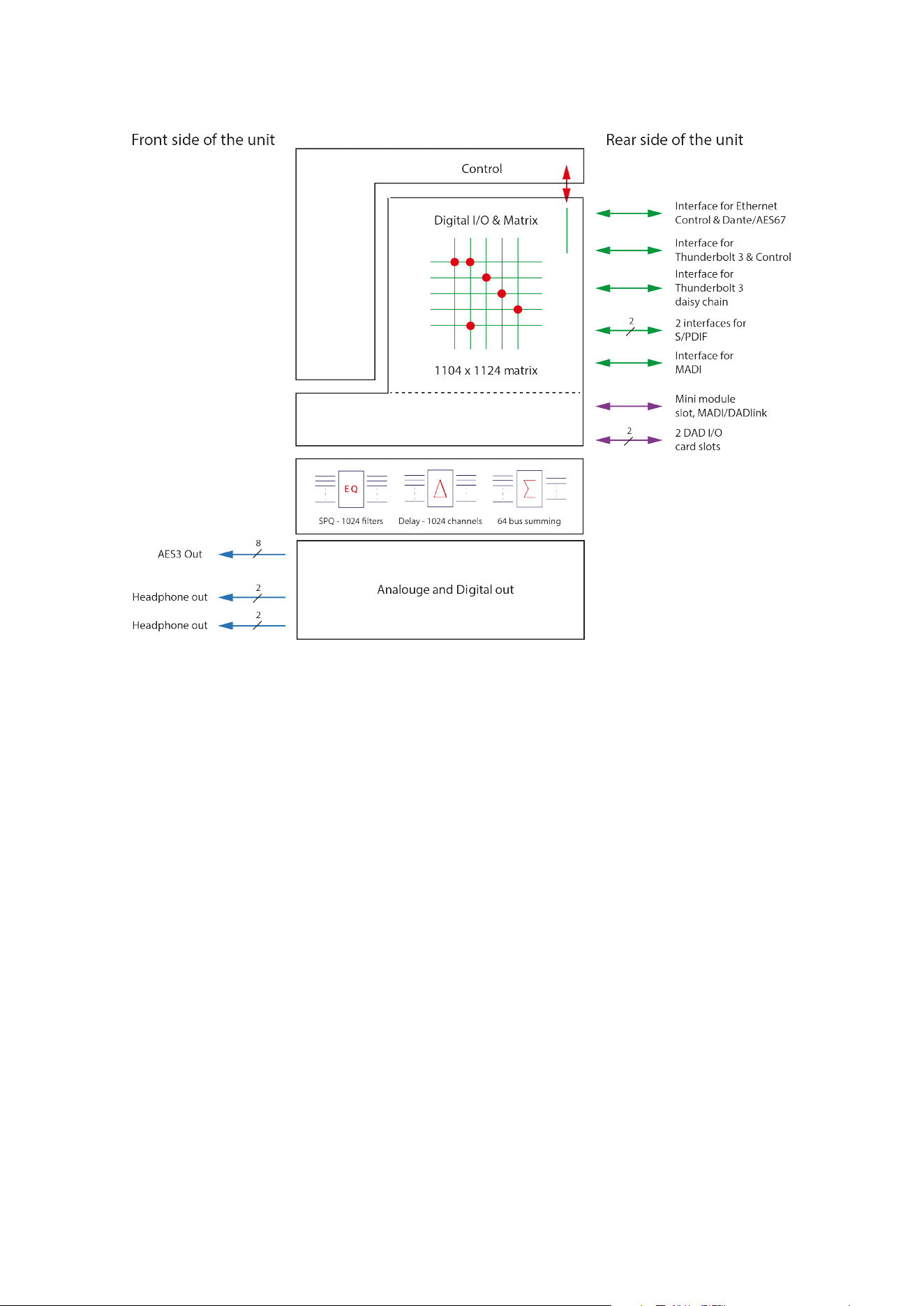
Figure 1: Block diagram of the unit
General description 7

Before you start
Place your Control 01/02 on a hard and dry surface or mount it into a 19-inch rack and leave plenty of room for
ventilation.
To meet the EMC requirements of directives EN 55032 and FCC 47 CFR part 15, and to obtain the highest
performance of the Control 01, you must use good-quality and correctly shielded cables for all external
connections when installing Control 01. For the power connection, a regular unshielded power cable with a
proper protective earth conductor can be used.
Make sure that your sound system is at a safe volume level.
8 Control 01 and 02 Installation Guide

Mechanical installation and low fan
noise
Control 01 and 02 are fitted with two very quiet fans to ensure optimum operating temperature. Under normal
operating conditions and with correct installation, the fans are inaudible in the studio environment. The fans are
temperature-controlled, i.e., the rotation speed, and thereby noise depends on the temperature inside Control 01/
02.
The optimal air flow is through the ventilation openings in the front panel to the rear of the unit. When the unit is
installed, considerations must be made to ensure proper air circulation for the air leaving the rear of the unit. The
speed of the low-noise fan will be automatically increased to maintain a low internal temperature if there is
insucient airflow. If the internal temperature exceeds 60°C / 140°F, a temperature alarm will appear in the
DADman software and is also indicated by the red error LED on the front panel.
Before you start 9

Network configuration
Control 01 and 02 are equipped with two Gigabit Ethernet connectors, and internally they feature an Ethernet
switch, a controller part, and a part for the IP Audio option powered by Dante™. The network connectors can
operate as two “parallel” connectors for the internal switch, or as dual connectors for redundant IP audio
operation. In this case, controlling the unit is done via Net port 1.
Control 01 and 02 have two or three dierent IP addresses:
▪ One for the unit control via DADman (Main CPU).
▪ A second for the primary Dante IP audio in single mode.
▪ An optional third IP for the secondary Dante IP audio in redundant mode if that is utilised on the Net 2
connector.
The factory default IP setting of the controller port (Main CPU) of the Control 01 is DHCP. This IP address can be
changed manually via DADman or set to be automatically assigned by a DHCP server / router on the network.
10 Control 01 and 02 Installation Guide

Control software
installation
The DADman control program operates on any Windows- or macOS-based computer and is frequently updated
to ensure compliance with the latest OS versions.
This section will take you through the installation procedure for the DADman computer control program. Control 01
and 02 are controlled from a PC or MAC via the Thunderbolt 3 connection or by a network connection.
▪ For control via a network connection, the PC / Mac and Control 01 or 02 units must be connected on the
same subnet, e.g. 255.255.•••.•••.
▪ For control via Thunderbolt 3, the DAD Thunderbolt 3 driver must be installed.
Control software installation 11

Installing the DADman remote
control program
1. Visit https://www.dynaudio.com/control, select your product, and click Download on the product page.
Please note that there are two separate program downloads: one for Windows and one for macOS.
2. Install the DADman software following the provided instructions from the installer.
3. Create a shortcut for the DADman program on the desktop.
4. Double-click on the DADman icon and launch the DADman application.
12 Control 01 and 02 Installation Guide
Connect your Control 01 or 02 to
DADman
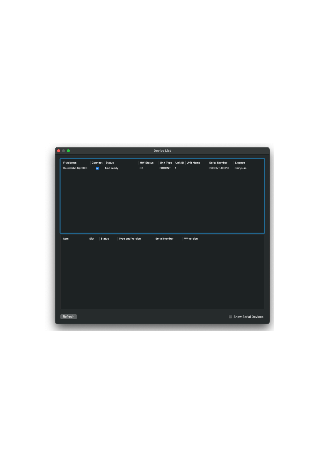
Control 01 and 02 can be controlled via Thunderbolt or Ethernet. At the first start-up, the DADman window may
be blank as no units are yet connected. In the top menu bar, select Tools > Device List, and the window will
display a list of the discovered units. If the unit is connected via Thunderbolt, this will appear in the list. If there is
no Thunderbolt connection, the units can be connected via Ethernet. If a unit on the Ethernet does not appear in
the list, apply “Refresh” to discover the Control 01 over Ethernet. The Device List window is shown in Figure 1. A
unit will always be discovered, but depending on your network configuration, it must be set to either DHCP or
Manual IP addressing. The unit type displayed is “PROCNT”.
In order to attach the unit to DADman, the connect box has to be checked.
Figure 2: DADman Device list
NOTE:
If the DAD Thunder|Core Thunderbolt driver is installed on the computer where DADman is running, the software
will automatically connect via Thunderbolt to Control 01 or 02 and not via Ethernet.
Control software installation 13

Assigning the IP address for the computer and the Control 01 and
02
When the DADman program is installed, you can finalise the network configuration of Control 01 or 02. You have
the option of using fixed IP addresses or IP addresses assigned via DHCP. DHCP can be auto-assigned via the
Ethernet port by itself or via an external DHCP server, which provides IP addresses for all units on your network.
Fixed IP address
You must have a preferred range of IP addresses and a network mask for the computer network, as well as the
connected Control 01 and 02 units.
1. Configure your computer’s IP address and network mask via the computer control panel to e.g. 10.0.7.25
| 255.255.255.0
Select Control 01 or 02 in the DADman Settings / Device List menu by right-clicking on the unit line and selecting
“Network settings”.
2. In DADman, configure each Control 01 or 02 in turn with a unique IP address and the preferred network
mask, e.g. 10.0.7.21 | 255.255.255.0. In this window, you can also configure the Dante IP audio network
settings.
When you are done, you can connect more than one Control 01 or 02 to the network, and they will appear in the
DADman Device List.
Automatic IP address
To automatically assign IP addresses to Control 01 and 02, you must have a network with a DHCP server that will
allocate the IP addresses; otherwise, the IP addresses will be self-assigned.
Configure your computer’s IP address via the computer control panel to use DHCP. Select the Control 01 or 02 in
the DADman Tools / Device List menu by right-clicking on the unit line and selecting “Network settings”. If you have
more Control 01 or 02 units connected, they will all be configured with an IP address via DHCP.
Once the DHCP system has allocated an IP address to the unit, it will appear in the DADman Device List with the
name PROCNT.
14 Control 01 and 02 Installation Guide
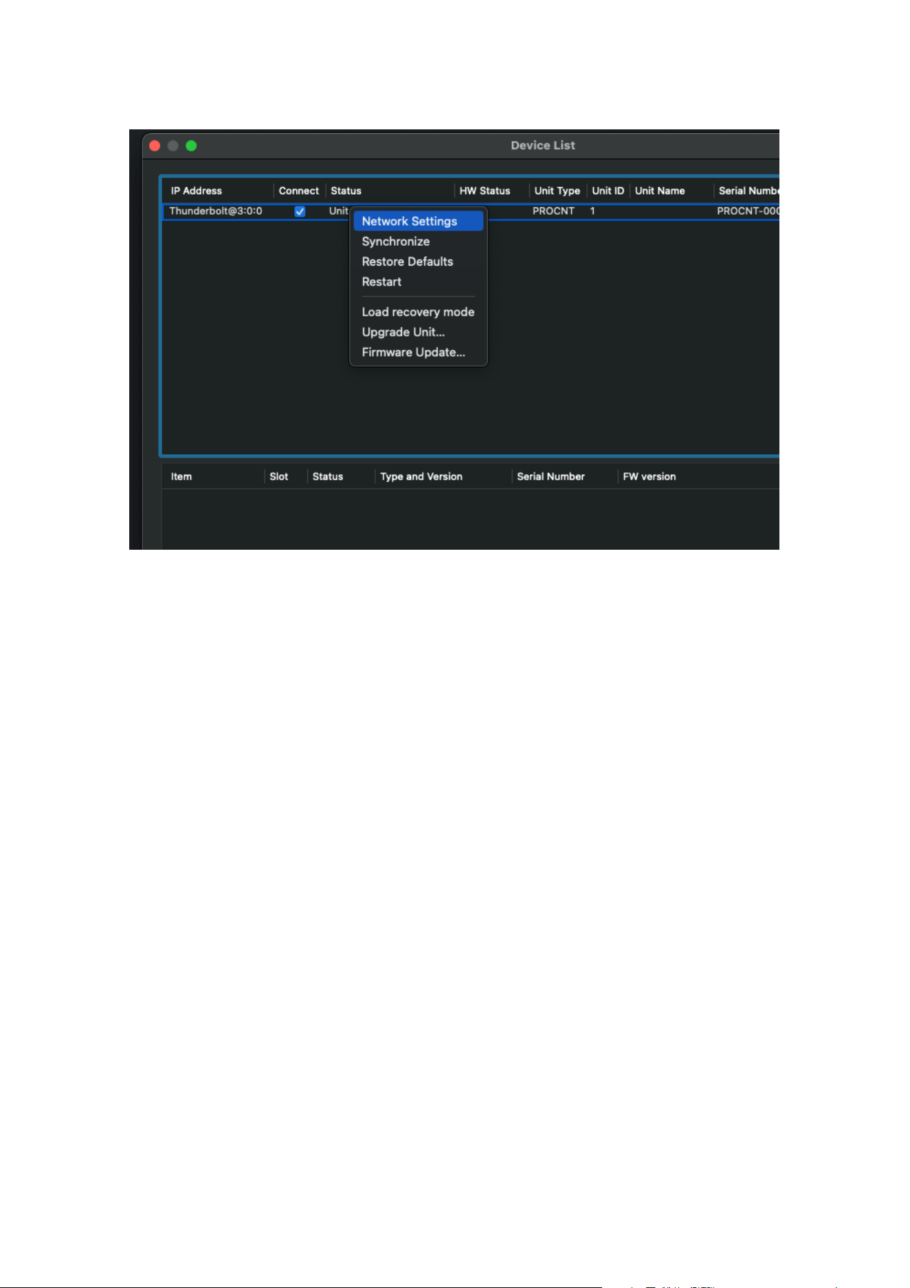
Figure 3: DADman Device list with settings
NOTE:
To ensure the proper function of Control 01 and 02, the routing and sample rate configuration must be set
correctly via DADman.
Control software installation 15
Installation of Thunder | Core driver
for macOS
The driver software must be installed completely before it can function correctly.
When you install the driver, it is of no importance whether units or other peripheral devices are connected to the
Thunderbolt 3 / USB-C port on the computer. In the process described below, no devices are connected before
installation.
This is the installation sequence:
1. Copy the driver .pkg file to the computer desktop and double-click to start the installation.
2. Follow the installation instructions. Click Next and then Install.
3. Enter Administrator password and click Install.
4. If the driver has not been installed before on the computer, you get the message “System extension
blocked”. Click on Open Security Preferences.
5. In the “Security and Privacy” window, you may have to click on the lock symbol in the bottom left corner,
unlock settings, and click Allow.
6. Restart the Computer and open the Thunderbolt 3 driver application, and connect the Control 01 or 02
Thunder|Core interface to the USB-C / Thunderbolt 3 port on the Computer. Ensure you are using a high-
speed (20 Gbps) Thunderbolt 3 USB-C cable.
For more information on how to install and configure the Thunderbolt 3 driver, please refer to the Thunder|Core
installation guide at https://www.dynaudio.com.
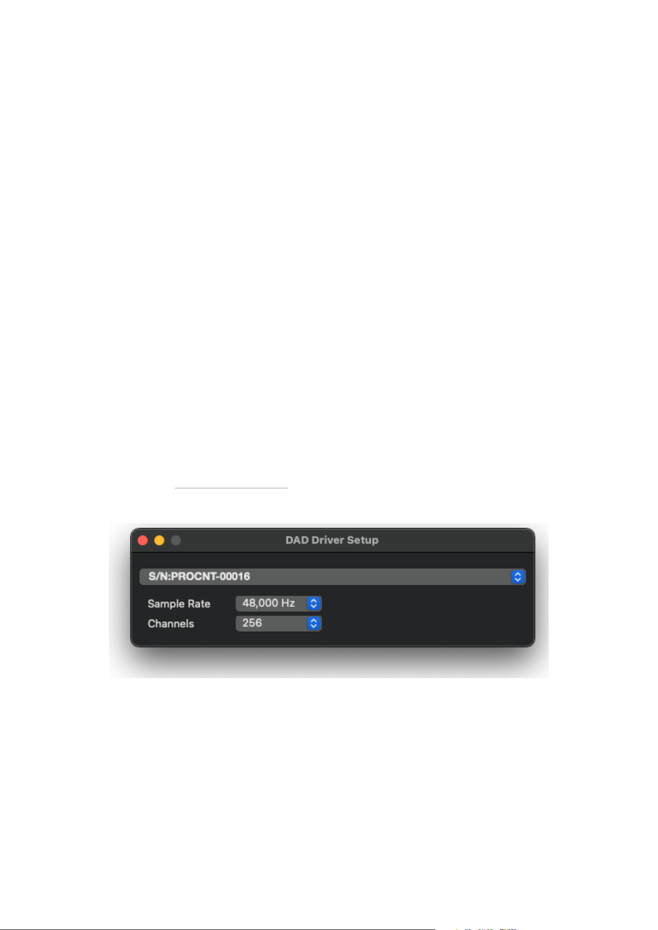
Once the driver is installed, the device can be attached via the setup window.
Figure 4: DAD Driver setup window for macOS
16 Control 01 and 02 Installation Guide
Installation of Thunder | Core ASIO
driver on Windows PC
The driver software must be installed completely to function correctly.
When you install the driver, it is of no importance whether units or other peripheral devices are connected to the
Thunderbolt 3 / USB-C port on the computer. In the process described below, no devices are connected before
installation.
This is the installation sequence:
1. Copy the driver .msi Windows installer file to the computer desktop and double-click to start the
installation.
2. Follow the installation instructions. Click Next and then Install.
3. Once the driver is installed, open your audio application and choose the Digital Audio Denmark ASIO
driver.
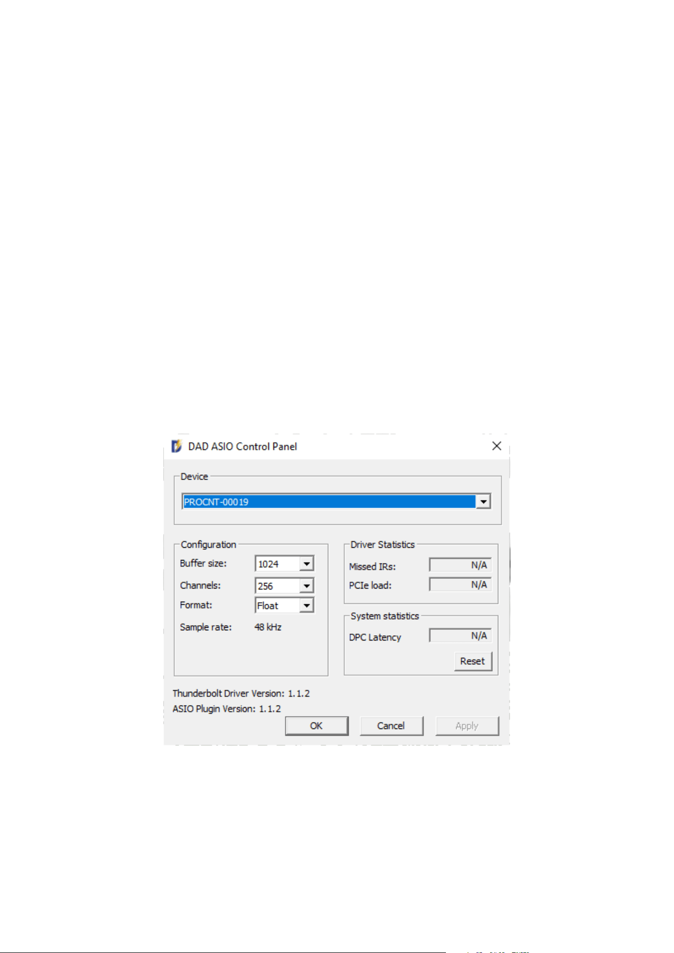
4. To configure the ASIO driver, open the ASIO dialogue window in the audio configuration section of your
audio application.
5. Configuration can be done on the parameters shown in Figure 5.
Figure 5: ASIO driver configuration window
NOTE:
The DAD ASIO control panel is accessible as a stand-alone configuration window or, if your DAW audio
application supports this, from inside the audio configuration dialogue.
Control software installation 17
Operation
Control 01 and 02 are controlled from a Mac or Windows computer via the Thunderbolt connection or the
Ethernet port on the rear panel (Net 1) and configured by the DADman software running on the computer. On the
front panel, you can monitor some of the primary settings.
On the right side of the unit, there are two ¼-inch stereo jack connectors for headphones. The headphone level
and configuration are managed via the DADman software, where the outputs can be attached as headphone
monitor outputs managed by the Pro|Mon monitor profile in the DADman software, enabling very flexible
monitoring configurations, as well as integration to the Control Link monitor operation module and Avid EUCON™
for control from Avid EUCON-enabled devices.
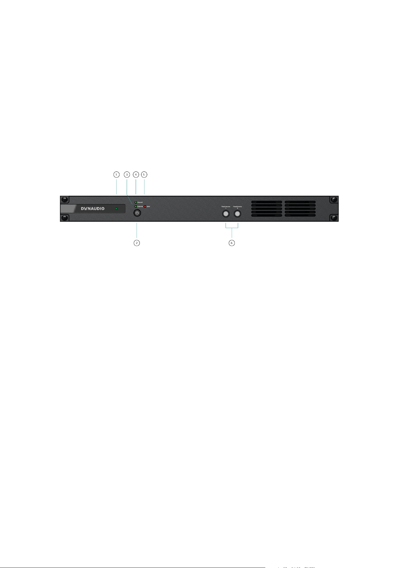
Figure 6: Front panel layout
18 Control 01 and 02 Installation Guide

Front panel layout
1. Dynaudio Logo. Green LED indicates that the unit is turned on and flashes when going into standby (o).
2. On / Standby button. Note that the unit automatically returns to the latest power state (on or standby) if it is
power cycled via the mains power. Press once to turn the unit on. Press and hold while the power LED is
blinking to turn the unit into standby-o mode.
3. External sync source two-colour indicator. The green LED indicates that the external sync source is
functioning properly, while the red LED indicates an insucient sync signal.
4. Internal sync indicator. The green LED shows the internal or external sync source.
5. Error indicator: Red LED. Indication is related to hardware performance and can be triggered by
temperature overload, fan error, DAD I/O card failure, or general internal boot error. A more specific error
indication will be visible in DADman.
6. Two stereo and ¼-inch jack connectors for stereo headphone output.
Operation 19
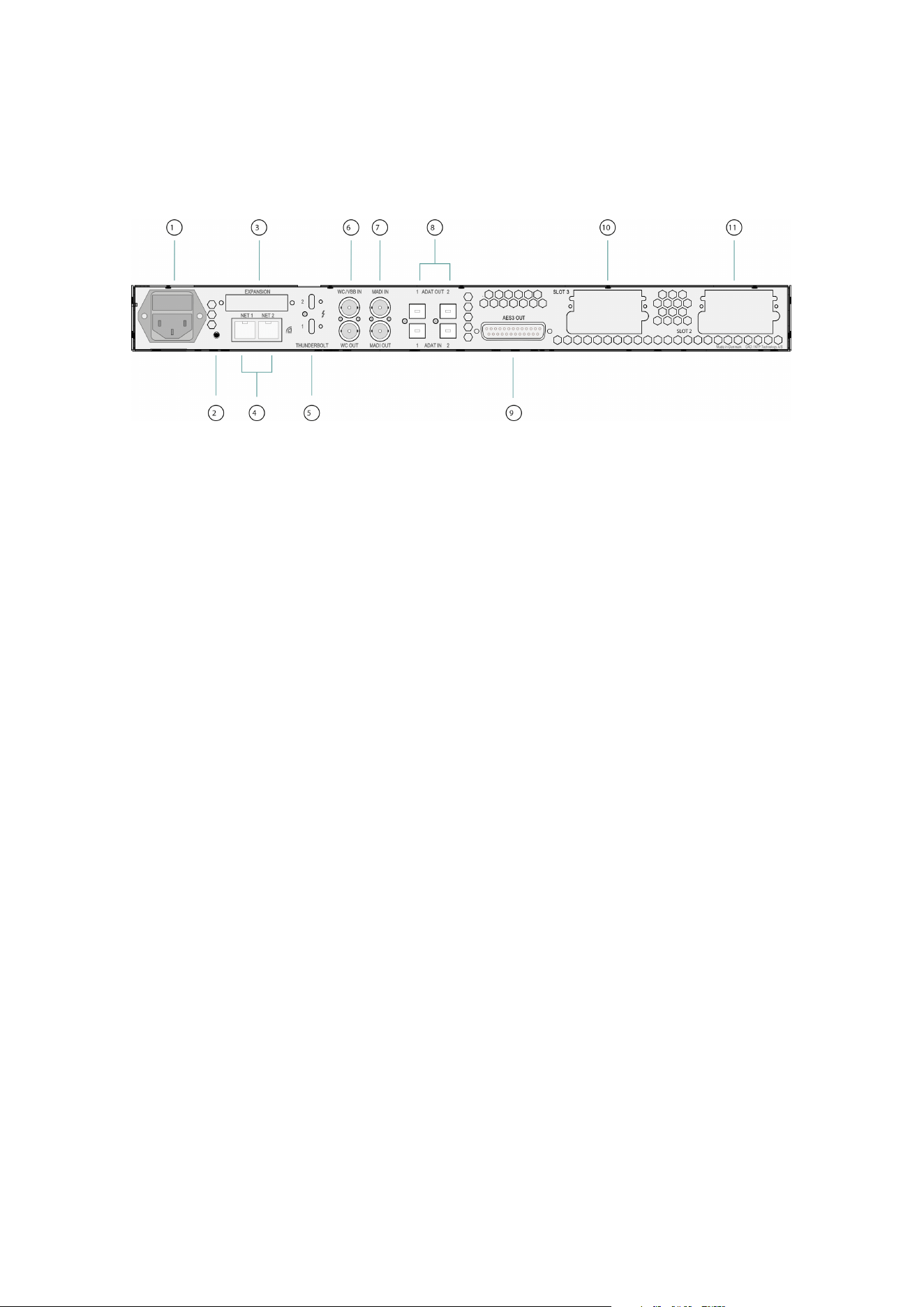
Rear panel connections
Below is the layout of the rear panel of the Control 01 and 02.
Figure 7: Rear panel layout
1. Mains power connector.
2. “Reconfig” button. Please refer to the section below for further details.
3. Expansion slot for optional dual MADI I/O mini module via optical or coaxial SFP modules. The module
also supports our DADlink format.
4. RJ45 Ethernet connectors. Two ports for Control and Dante AoIP. Connectors can be set in switched or
redundant mode for Dante. In redundant mode, the control network has to be connected to port 1.
5. Thunderbolt 3 interface for connection to a computer and for an expansion unit or other peripheral
interfacing.
6. Word Clock or Video Black Burst synchronisation input (configurable), BNC connector, and Word Clock
output.
7. MADI I/O BNC connectors.
8. Two sets of TOSLINK optical ADAT input and output connectors. Input can also be set to S/PDIF.
9. AES 3 output DB25 female connector.
10. Slot 3 for Optional multi-format DAD I/O Cards (Slot 1 is the internal card).
11. Slot 2 for Control 02 analogue line outputs.
20 Control 01 and 02 Installation Guide
Digital I/O and Network Connections
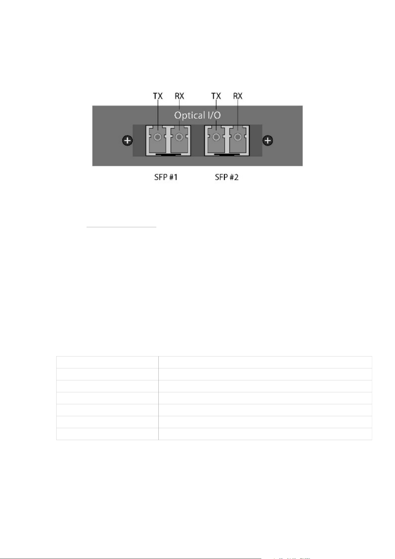
Dual MADI SFP I/O mini-module (optional)
Figure 8: Dual MADI SFP I/O mini-module
The Dual SFP module can operate as a MADI interface or as DADlink. The Dual SFP module can be installed with
one or two “Small form-factor pluggable” (SFP) transceiver modules supporting Optical LC connection or mini
coax HD-BNC electrical connection. The mini coax HD-BNC electrical SFP connection works only with MADI. The
optical SFP modules are standard types that support single-mode or multi-mode optical fibres of various types, as
well as dierent wavelengths.
For MADI, typically 1300nm types are used. Each SFP module has a receiver and a transmitter part and can be
used for MADI audio I/O, DADlink, or a combination of both. When using DADlink optical SFP modules, they have
to be Gigabit/1000BASE types. For MADI optical SFP modules, there can be both 1000BASE and 100BASE
types. The right part of the SFP connector is the receiver, and the left part is the transmitter.
Dual Gigabit Ethernet RJ45 connectors
The dual Ethernet connectors are used for remote control of the unit via DADman software over the network, as
well as for Dante IP audio connections. Net 1 should be used for remote control and the primary Dante interface,
while Net 2 can be used for either the secondary Dante interface or as a switched port for connecting other
devices.
Pin 1 BI_DA+
Pin 2 BI_DA-
Pin 3 BI_DB+
Pin 4 BI_DC+
Pin 5 BI_DC-
Pin 6 BI_DB-Pin 7
Pin 8 BI_DD-
Table 1: Dual Gigabit Ethernet RJ45 connectors
Operation 21
Thunderbolt 3 connectors
Two USB-C type connectors for connecting via Thunderbolt 3. The two connectors have the same functionality.
One can be connected to the computer, and the other to an additional audio interface for expansion or to a
standard USB-C peripheral device that provides non-audio functionality. Two chassis holes enable the use of
ThunderLok 3L Thunderbolt Connector Retention clips.
NOTE:
A high-speed Thunderbolt 3 cable has to be used for interconnection. The cable should be the following type:
Thunderbolt 3 20 Gbps or 40 Gbps USB-C cable, and preferably Intel Certified.
MADI connectors
Coaxial BNC connector for input and output of MADI signals via 75 Ohm Coax cables.
Sync connectors
Coaxial BNC connector for Clock input synchronisation, and Word Clock output. The input clock format can be
Word Clock or Video Black Burst (VBB).
ADAT Connectors
Two TOSLINK Inputs and two outputs support ADAT for 16 channels of IO. S/PDIF is supported on input only.
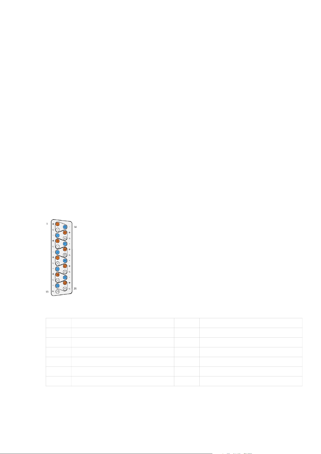
AES3 Output Connections (D-sub Connector)
There are 8 AES3 output connections, totalling 16 audio channels, available via a 25-pin D-sub female connector
on the rear panel. The connections are balanced, as shown with Tascam pinning below.
Figure 9: AES3 Output Connections
1 AES3 OUT 8 + 14 AES3 OUT 8
2 GND 15 AES3 OUT 7 +
3 AES3 OUT 7 - 16 GND
4 AES3 OUT 6 + 17 AES3 OUT 6 -
5 GND 18 AES3 OUT 5 +
6 AES3 OUT 5 - 19 GND
7 AES3 OUT 4 + 20 AES3 OUT 4 -
Table 2: AES3 Output Connections
22 Control 01 and 02 Installation Guide

8 GND 21 AES3 OUT 3 +
9 AES3 OUT 3 - 22 GND
10 AES3 OUT 2 + 23 AES3 OUT 2 -
11 GND 24 AES3 OUT 1 +
12 AES3 OUT 1- 25 GND
13 N.C.
Operation 23

Analogue I/O Connections on
Control 02 and optional DAD I/O
Cards
The Control 02 has the analogue line output card installed, providing 8 outputs for analogue speakers.
There are two slots available for optional DAD I/O expansion cards. There are many options available, including
8-channel mic / line inputs, 8-channel line outputs, additional AES, SDI, and additional Dante IP ports. If an
analogue card is installed, the pinout follows the Tascam standard.
1 AIN/OUT 8 + 14 AIN/OUT 8 -
2 GND 15 A/IN/OUT 7 +
3 AIN/OUT 7 - 16 GND
4 AIN/OUT 6 + 17 AIN/OUT 6 -
5 GND 18 AIN/OUT 5 +
6 AIN/OUT 5 - 19 GND
7 AIN/OUT 4 + 20 AIN/OUT 4 -
8 GND 21 AIN/OUT 3 +
9 AIN/OUT 3 - 22 GND
10 AIN/OUT 2 + 23 AIN/OUT 2 -
11 GND 24 AIN/OUT 1 +
12 AIN/OUT 1- 25 GND
13 N.C.
Table 3: Analogue I/O Connections on Control 02 and optional DAD I/O Cards
24 Control 01 and 02 Installation Guide
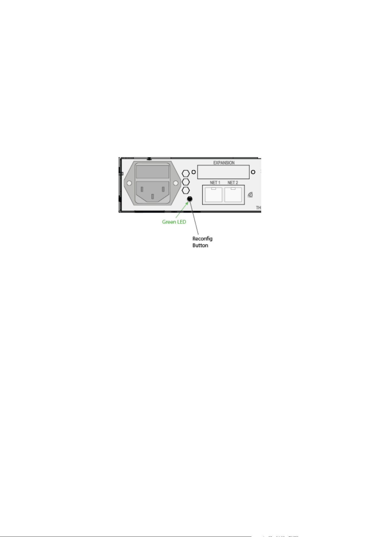
Reconfig button
The “Reconfig” button on the back of the Control 01/02 should not be used during normal installation. It is
generally intended as a last-resort recovery function in case something goes wrong during the programming of IP
addresses or a software upgrade, e.g., an unintended power loss. It allows the Control 01/02 to start in various
“basic” modes so it can be restored without having to be returned to the factory.
The “Reconfig” button is accessed via a hole in the rear panel using a pen or a similar pointed item. A green LED
is visible through the hole. When the “Reconfig” button is activated, the LED will light up, indicating the two
reconfig modes of the CONTROL 01.
Reconfig mode
Figure 10: Reconfig button
Reconfig button pushed while the unit is powering up – Green LED turns ON.
The Control 01/02 enters a recovery mode. In this mode, only a basic boot software is operative in the unit, and
new software can be downloaded via the DADman software. This mode is used if the software in CONTROL 01 is
not operational or malfunctioning for some reason. The IP address settings of the unit are the last setting used in
the unit.
Reconfig IP short push while the unit is in reconfig mode and Green LED is on – Green
LED turns OFF.
The Control 01/02 remains in reconfig mode as described above. The IP address settings of the unit are,
however, set to DHCP. If there is no DHCP server on the network, the Control 01/02 will default to IP address
10.0.7.20 / 255.255.0.0 after approximately 2 minutes.
The selection of either of the two recovery modes is fixed after selection. The Control 01/02 will start with a basic
boot software and IP configuration. It will not be operational until a proper firmware has been downloaded via the
DADman software and the device has been restarted. By enabling recovery mode with the default IP address and
network configuration, the unit can always be identified on a network via the default setup.
NOTE:
Note that the IP address referred to is the IP address of the controller/management interface of the unit. This is not
the IP address of the IP audio interface if one is installed. This IP address cannot be accessed in Recovery or
Restore Defaults mode.
Operation 25

Specifications
Audio Specifications
Analogue Headphone output
Modulator resolution, format 32 × oversampling, 32-bit PCM
PCM (DXD) sample rates 44,1, 48, 88.2, 96, 174.4, 192, 352,8, 384 kHz
Dynamic range (A) > 120 dB
THD+N(A) < -100 dB @ -3 dB FS
Cross talk < 110 dB
Headphone impedance 18 to 600 Ohms
Output impedance < 1 Ohm
Maximum output level Adjustable from -80 dBu to 19 dBu in steps of 0.1 dB
Analogue Line output (Control 02 only) 8 output channel pristine D/A conversion
Sample rates 44.1 to 384 kHz and DSD 64/128
Dynamic Range > 125 dB
THD+N < 115 dB @ -3 db FS
Gain staging made with relays
26 Control 01 and 02 Installation Guide

Digital I/O and Synchronisation
Digital I/O formats / Supported sample rate
Dante™ IP audio and ADAT/SMUX up to 192 kHz
Thunderbolt 3 and MADI up to 384 kHz
DADLink up to 384 kHz
Synchronisation Word Clock, Video Black Burst, Dante, ADAT, and MADI
Network Interface 2 × 1000BASE-T, RJ45 connector, 4-pair connection
Thunderbolt 3 Interface
2 × USB-C type connectors, supporting link functionality and
15 W power on each port.
DADLink Interface
2 × SFP connectors for Gigabit SFP modules, supporting
multi-mode LC optical fibre connections.
Latency is below 1 microsecond between interconnected
units.
The overall latency is defined by the system delay set for all
the units, which is usually 7 samples. All I/O connections
across units are 100% aligned in phase.
Channels and Sample rates per link 128 channels @ 44.1 and 48 kHz
64 channels @ 88.2 and 96 kHz
32 channels @ 176.4 and 192 kHz
16 channels @ 352.8 and 384 kHz
NOTE:
You can double the channel count by using two fibre links.
Specifications 27

Electrical Specifications
Power consumption
Digital section 15 W
DAD I/O Options 30 W maximum
Thunderbolt power 2 × 15 W maximum
Mains 90 W maximum
Input voltage 90 to 260 VAC
100 to 240 VAC Nominal, 47 to 63 Hz
Mains fuse, mounted in an IEC connector 1 A, T1AH/250V
Safety compliance IEC 62368-1:2020+A11 2020
The power supply cord must be at least a light sheathed
flexible cord according to IEC 60227 (designation 60227 IEC
52) and include a protective earth conductor with green-and-
yellow insulation. Cross-sectional areas min. 3 × 0.75 mm
2
Mains line plug type
110 to 125V UL817 and CSA C22.2 no 42
220 to 230V CEE 7 page VII, SR section 107-2-D1/IEC 83 page C4
240V
BS 1363 of 1984. Specification for 13A fused plugs and
switched and unswitched socket outlets.
28 Control 01 and 02 Installation Guide

Mechanical Specifications
Chassis standard 19 inches, 1 rack unit
Chassis depth, without connectors mounted 32 cm / 12.6 inches
Chassis body width 43.5 cm / 17.2 inches
Weight 2.4 kg / 5.3 lbs.
Environmental Specifications
Operating Temperature 0 to 45º C / 32 to 113º F
Humidity 20 to 85% (non-condensing)
EMC compliance
- IEC 55032/CISPR 32
- IEC 55035/CISPR35
- IEC 61000-3-2
- IEC 61000-3-3
- VCCI-CISPR 32
- ICES-003
- AS/NZ CISPR32
- FCC part 15, Subpart B
↻ 2025-11-28
Specifications 29