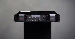

Delta series, manufactured by MC2 Audio
DELTA 40/80/100 DSP
Operating Instructions
Dynaudio A/S
8660 Skanderborg, Denmark
www.dynaudio.com

Page 2 Delta Series D40/80/100 DSP Operating Instructions

Delta Series D40/80/100 DSP Operating Instructions Page 3
CONTENTS
DECLARATION OF CONFORMITY ........................................................................ 6
THANKS ................................................................................................................7
INTRODUCTION ....................................................................................................7
IMPORTANT SAFETY INSTRUCTIONS ................................................................ 8
INSTRUCTIONS DE SECURITE IMPORTANTES .................................................. 9
Installing Your Amplifier: Electrical Considerations ........................................ 10
Installing Your Amplifier: Mechanical Considerations ..................................... 12
Installing Your Amplifier: RF Emissions .......................................................... 12
About Your Amplifier: Dynamic Amplifier Performance Measurements ........ 13
Connecting To Your Amplifier: Line Inputs and Outputs .................................. 14
Connecting To Your Amplifier: Speaker Outputs .............................................. 15
Connecting To Your Amplifier: Bridged (Mono) Operation ............................... 16
Operating Your Amplifier: Front Panel Controls and Indicators ...................... 17
Operating Your Amplifier: Rear Panel Sockets and Switches ......................... 19
Operating Your Amplifier: Initial Set-up and Switching On .............................. 21
Switching On… ......................................................................................................................... 21
Inside Your Amplifier: DSP Layout, Configurations and Routing ..................... 22
Source Choices and Selection ................................................................................................ 23
Input Processing Channels ..................................................................................................... 24
Mix Matrix Section ................................................................................................................... 24
Power Amplifier and Auxiliary Output Processing Channels ................................................. 25
Independent Network Audio Outputs ..................................................................................... 26
Operating Your Amplifier: Directly Editing Audio Parameters ........................ 27
Overview .................................................................................................................................. 27
Input Gain ................................................................................................................................ 28
Input Delay .............................................................................................................................. 28
Input Parametric EQ Bands 1 through 8 ................................................................................. 29
Output Gain ............................................................................................................................. 30
Output Polarity ........................................................................................................................ 30
Output Delay ............................................................................................................................ 30
Output High Pass Filter .......................................................................................................... 31
Output Low Pass Filter ........................................................................................................... 31
Output Parametric EQ Bands 1 through 9 .............................................................................. 32
Output Limiters: Program Limiter ........................................................................................ 33
Output Limiters: Peak Limiter ............................................................................................... 33
Output Matrix Gains ................................................................................................................ 34

Page 4 Delta Series D40/80/100 DSP Operating Instructions
Operating Your Amplifier: Advanced Editing Features .................................... 35
Overview .................................................................................................................................. 35
Selecting Available Sources (Analogue, AES, Network Audio) .............................................. 35
Switching from Analogue to AES Sources .............................................................................. 36
Choosing Sources for Input Processing and Failover Configuration ..................................... 37
Changing Network Output Source .......................................................................................... 40
Changing Crossover Configuration ......................................................................................... 42
Using Free Assign Mode ......................................................................................................... 43
Bridged Mode for Output Pairs ............................................................................................... 44
Resetting Audio Parameters .................................................................................................. 46
Ganging Channels for Editing ................................................................................................. 46
Operating Your Amplifier: Storing and Recalling Settings.............................. 48
Memory Overview .................................................................................................................... 48
Storing a Memory… ................................................................................................................. 49
Recalling a Memory… ............................................................................................................. 50
Operating Your Amplifier: System Adjustments .............................................. 51
Overview .................................................................................................................................. 51
Operating Your Amplifier: Remote & External Interfaces (Incl. Dante) ........... 52
Overview .................................................................................................................................. 52
Remote Control Software Choices .......................................................................................... 52
Configuration of the Remote Interface ................................................................................... 53
Wireless Connection with DeltaDirect iPad App .................................................................... 58
GPIO Operation ........................................................................................................................ 59
Operating Mode ....................................................................................................................... 59
RS485 Relay ............................................................................................................................ 59
VCA Mode ................................................................................................................................ 60
Standby Mode .......................................................................................................................... 61
Mutes Mode ............................................................................................................................. 61
Memory Recall Mode .............................................................................................................. 62
General Purpose Output Pins ................................................................................................. 63
Operating Mode Combinations ............................................................................................... 64
Dante Interface Configuration ................................................................................................ 65
Operating Your Amplifier: Using & Clearing Security; Defaulting Settings .... 66
Locking the Front Panel ......................................................................................................... 66
Entering the Password to Complete the Locking Operation .................................................. 67
Unlocking ................................................................................................................................ 67
Default Settings ...................................................................................................................... 67
Clearing Standby ..................................................................................................................... 67
Entering Start-up Control Codes ............................................................................................ 67
Clearing Security — Forgotten Unlock Code .......................................................................... 68
Looking After Your Amplifier: Maintenance .................................................... 69
Looking After Your Amplifier: Warranty .......................................................... 69
Performance Of Your Amplifier: Specifications ............................................... 70

Delta Series D40/80/100 DSP Operating Instructions Page 5
Appendix I: Limiters and How to Set Them Correctly ...................................... 73
Program Limiter ..................................................................................................................... 73
Peak Limiter ............................................................................................................................ 74
Setting Accurate Limiter Thresholds — Program Limiter ...................................................... 77
Amplifier Outputs’ Program Limiter Lookup Table ............................................................... 78
Auxiliary Outputs’ Program Limiter Lookup Table ................................................................ 79
Setting Accurate Limiter Thresholds — Peak Limiter ............................................................ 80
Setting Appropriate Attack and Release Times ..................................................................... 80
Appendix II: Upgrading Firmware and Loading Presets ................................. 82
Amplifier Communications Set-up ......................................................................................... 82
Download the Files ................................................................................................................. 82
Connect To The Amplifier ....................................................................................................... 83
Choose What To Load .............................................................................................................. 83
Start The Update! .................................................................................................................... 84
What If It All Goes Wrong… ..................................................................................................... 84
Appendix III: Speaker Backup Inputs (DSP40 Only) ........................................ 86

Tel: +44 (0) 1404 44633 | Email: [email protected].uk | VAT: GB 589 4223 04 | EORI: GB589422304000 |
www.mc2-audio.co.uk | www.facebook.com/mc2audcio
DECLARATION OF CONFORMITY
We, the manufacturer:
XTA Electronics Ltd
(TRADING AS MC
2
Audio)
Units 6-7 Kingsgate
Heathpark Industrial Estate
Honiton, Devon
England
EX14 1YG
acknowledge our responsibility and self-certify the following products:
Kind of equipment: Audio amplifier
Commodity Code: 8518400090
Type Designation: I38/I68/I64
Delta40DSP, Delta80DSP, Delta100DSP
Delta20ND, Delta40ND, Delta80ND, Delta100ND, Delta120ND
DPA40, DPA80, DPA100
DNA20, DNA40, DNA80, DNA100, DNA120
T500, T1000, T2000, T4-250
Ti500, Ti1000, Ti1500, Ti2000, Ti3500, Ti4-250
E15, E25, E45, E475
S800, S1400
and all OEM/variants of these models
are manufactured in accordance with EMC Directive 2014/30/EU (CE and UKCA), in compliance with the following norm(s)
or document(s):
Technical Regulations: EN61000-3-2:2014 (Mains Harmonic)
EN61000-3-3:2013 (Mains Flicker)
EN55032:2015 (Emissions)
EN55032:2017 (Immunity)
and in accordance with the: Low Voltage Directive 2014/35/EU (CE and UKCA)
in compliance with the following norm(s) or document(s):
Technical Regulations: EN/IEC62368-1:2020 (Audio, Video & Communication Safety)
and in accordance with the Directive 2011/65/EU on the restricted use of certain Hazardous Substances in Electrical and
Electronic Equipment (RoHS2). We certify that the above-mentioned products are deemed compliant according to the
details given in the directive.
Signed: ……………………………………………………………………
Name: Alex Cooper
Position: Research and Development Manager
Date: Jan 2024

Delta Series D40/80/100 DSP Operating Instructions Page 7
THANKS
Thank you for choosing a Delta Series amplifier for your application.
Please spend a little time reading through this manual, so that you obtain the best possible
performance from the unit and become familiar with its operating requirements.
All MC
2
products are carefully designed and engineered for cutting-edge performance and
world-class reliability. If you would like further information about this or any other MC
2
product, please contact us.
We wish you many years of service from this amplifier and look forward to hearing from you
in the near future.
INTRODUCTION
The Del
ta Series has been designed to combine incredible audio power and performance with
ultra-flexible connectivity for both remote control and audio. Exemplary audio processing is
assured through the use of XTA’s DSP platform, and power amplifier capabilities are taken
care of with high efficiency output stages and a generous power supply.
Accepting analogue, AES3 digital and optional Dante networked audio, the Delta DSP
amplifiers can connect to any source and make it available over the network, as well as
processing four additional channels with local analogue outputs to connect to non-DSP Delta
amplifiers. These auxiliary processed outputs can also be fed onto the network, and used by
non-DSP Delta amplifiers that have Dante cards fitted, or by any other Dante enabled device.
Connectivity for remote control is covered by USB, Ethernet and RS485, with relay of either
USB or Ethernet control via RS485 to work with legacy products. Configuration of the
amplifier’s processing is through the industry standard AudioCore application, with tuning
and monitoring of a network of Delta DSP amplifiers handled wirelessly by the dedicated
DeltaDirect iPad app.
With a range of power levels available in the Delta Series, the non-DSP amplifiers can be
networked to a single Delta DSP model, creating a powerful, efficient system that’s easy to
expand and adapt for use in live, install and everything in between.
#powermeetsprocessing
Page 8 Delta Series D40/80/100 DSP Operating Instructions
IMPORTANT SAFETY INSTRUCTIONS
CAUTION: RISK OF ELECTRIC SHOCK.
DO NOT OPEN
WARNING: Apparatus with CLASS I construction shall be connected to a MAINS socket outlet with a protective
earthing connection.
WARNING: To prevent injury, this apparatus must be securely attached to the rack in accordance with the
installation instructions.
1. Read these instructions.
2. Keep these instructions.
3. Heed all warnings.
4. Follow all instructions.
5. Do not use this apparatus near water.
6. Clean only with a dry cloth.
7. Do not block any ventilation openings, install in
accordance with the manufacturer’s instructions.
8. Do not install near any heat sources, such as
radiators, heat registers, stoves or other apparatus
(including amplifiers) that produce heat.
9. Do not defeat the safety purpose of the polarized or
grounding-type plug. A polarized plug has two blades
with one wider than the other. A grounding-type plug
has two blades and a third grounding prong. The wide
blade or the third prong are provided for your safety. If
the provided plug does not fit into your outlet, consult
an electrician for replacement of the obsolete outlet.
10. Protect the power cord from being walked on or
pinched particularly at plugs, convenience
receptacles and the point where they exit from the
apparatus.
11. Only use attachments/accessories specified by the
manufacturer.
12. Use only with the cart, tripod, bracket or
table specified by the manufacturer, or sold with the
apparatus. When a cart is used, use caution when
moving the cart/apparatus combination to avoid injury
from a tip over.
13. Unplug this apparatus during lightning storms or
when unused for a long period of time.
14. Refer all servicing to qualified service personnel.
Servicing is required when the apparatus has been
damaged in any way, such as if the power-supply cord or
plug is damaged, liquid has been spilled or objects have
fallen into the apparatus, the apparatus has been
exposed to rain or moisture, does not operate normally,
or has been dropped. This equipment contains a non-
user replaceable lithium battery for memory retention.
Should this battery fail and user settings be lost, do not
attempt to replace the battery yourself but return the
equipment to an authorised service centre.
15. Do not expose this equipment to dripping or
splashing and ensure that no objects filled with liquids,
such as vases, are placed on the equipment.
16. To completely disconnect this equipment from the
AC mains, disconnect the power cord from the mains
circuit breaker.
17. This unit is supplied with a 3-wire power cord. For
safety reasons, THE EARTH LEAD SHOULD NOT BE
DISCONNECTED IN ANY CIRCUMSTANCE.
18. Correct disposal of this product: This symbol
indicates that this product must not be disposed of with
household waste, according to the WEEE Directive
(2012/19/EU) and your national law. This product should
be taken to a collection center licensed for the recycling
of waste electrical and electronic equipment (EEE). The
mishandling of this type of waste could have a possible
negative impact on the environment and human health
due to potentially hazardous substances that are
generally associated with EEE. At the same time, your
cooperation in the correct disposal of this product will
contribute to the efficient use of natural resources. For
more information about where you can take your waste
equipment for recycling, please contact your local city
office, or your household waste collection service.
The lightning flash with arrowhead
symbol within an equilateral triangle is
intended to alert the user to the presence
0f uninsulated “dangerous voltage”
within the product’s enclosure that may
be of sufficient magnitude to constitute a
risk of electric shock to persons.
The exclamation mark within an
equilateral triangle is intended to alert
the user of important operating and
maintenance (servicing) instructions in
the literature accompanying the
appliance.
Delta Series D40/80/100 DSP Operating Instructions Page 9
INSTRUCTIONS DE SECURITE IMPORTANTES
ATTENTION: RISQUE DE CHOC ELECTRIQUE.
NE PAS OUVRIR
A
TTENTION: Appareils de construction de CLASSE I doit être raccordé au réseau électrique via une prise de courant
reliée à la terre.
ATTENTION: Pour éviter toute blessure, cet appareil doit être solidement fixé à la torture, conformément aux
instructions d'installation.
1. Lisez ces consignes.
2. Conservez ces consignes.
3. Respectez tous les avertissements.
4. Respectez toutes les consignes d’utilisation.
5. N’utilisez jamais l’appareil à proximité d’un liquide.
6. Nettoyez l’appareil avec un chiff on sec.
7. Veillez à ne pas empêcher la bonne ventilation de l’appareil
via ses ouïes de ventilation. Respectez les consignes du fabricant
concernant l’installation de l’appareil.
8. Ne placez pas l’appareil à proximité d’une source de chaleur
telle qu’un chauff age, une cuisinière ou tout appareil dégageant
de la chaleur (y compris un ampli de puissance).
9. Ne supprimez jamais la sécurité des prises bipolaires ou des
prises terre. Les prises bipolaires possèdent deux contacts de
largeur diff érente. Le plus large est le contact de sécurité. Les
prises terre possèdent deux contacts plus une mise à la terre
servant de sécurité. Si la prise du bloc d’alimentation ou du
cordon d’ali-mentation fourni ne correspond pas à celles de
votre installation électrique, faites appel à un électricien pour eff
ectuer le changement de prise.
10. Installez le cordon d’alimentation de telle façon que
personne ne puisse marcher dessus et qu’il soit protégé
d’arêtes coupantes. Assurez-vous que le cordon d’alimentation
est suffisamment protégé, notamment au niveau de sa prise
électrique et de l’endroit où il est relié à l’appareil; cela est
également valable pour une éventuelle rallonge électrique.
11. Utilisez exclusivement des accessoires et des appareils
supplémentaires recommandés par le fabricant.
12. Utilisez exclusivement des chariots, des diables, des
présentoirs, des pieds et des surfaces de travail recommandés
par le fabricant ou livrés avec le produit. Déplacez
précautionneusement tout chariot ou diable chargé pour éviter
d’éventuelles blessures en cas de chute.
13. Débranchez l’appareil de la tension secteur en cas d’orage
ou si l’appareil reste inutilisé pendant une longue période de
temps.
14. Les travaux d’entretien de l’appareil doivent être eff ectués
uniquement par du personnel qualifié. Aucun entretien n’est
nécessaire sauf si l’appareil est endommagé de quelque façon
que ce soit (dommages sur le cordon d’alimentation ou la prise
par exemple), si un liquide ou un objet a pénétré à l’intérieur du
châssis, si l’appareil a été exposé à la pluie ou à l’humidité, s’il
ne fonctionne pas correctement ou à la suite d’une chute. Pour
la mémorisation des paramètres, cet appareil contient une pile
au lithium non remplaçable par l’utilisateur. En cas de
défaillance de la pile et perte des réglages, n’essayer pas de
remplacer la pile par vous-même. Retourner votre appareil vers
une station technique habilité.
15. N'exposez pas cet équipement au fait de tomber goutte à
goutte ou au fait d'éclabousser et garantissez qu'aucun objet
rempli des liquides, comme les vases, n'est placé sur
l'équipement.
16. Pour complètement débrancher cet équipement de la
conduite principale de courant alternatif, débranchez la corde de
pouvoir du disjoncteur de conduite principale.
17. Cet appareil est fourni avec un cordon d'alimentation à 3 fils.
Pour les raisons de sécurité, L'AVANCE DE TERRE NE DEVRAIT
ÊTRE DÉBRANCHÉE DANS AUCUNE CIRCONSTANCE.
18. Mise au rebut appropriée de ce produit: Ce symbole
indique qu’en accord avec la directive DEEE (2012/19/EU) et les
lois en vigueur dans votre pays, ce produit ne doit pas être jeté
avec les déchets ménagers. Ce produit doit être déposé dans un
point de collecte agréé pour le recyclage des déchets
d’équipements électriques et électroniques (EEE). Une mauvaise
manipulation de ce type de déchets pourrait avoir un impact
négatif sur l’environnement et la santé à cause des substances
potentiellement dangereuses généralement associées à ces
équipements. n même temps, votre coopération dans la mise au
rebut de ce produit contribuera à l’utilisation efficace des
ressources naturelles. Pour plus d’informations sur ’endroit où
vous pouvez déposer vos déchets d’équipements pour le
recyclage, veuillez contacter votre mairie ou votre centre local
de collecte des déchets.
Le symbole représentant un éclair fléché
dans un triangle
équilatéral a pour but
d’alerter l’utilisateur de la pr
ésence
d’une “tension dangeruese” non isol
ée à
l’intérieur du boitier, pouvant être d’une
force suffisante pour constituer un risqué
d’
électrocution.
Le point d’exclamation dans un triangle
équilatéral a pour but d’alerter
l’untilisateur de la pr
ésence
d’instructions importantes concernant le
fonctionnement et la maintenance, dans
la documentation qui accompagne
l’appariel.
Page 10 Delta Series D40/80/100 DSP Operating Instructions
Installing Your Amplifier: Electrical Considerations
The amplifier has been manufactured to comply with your local power supply requirements,
but before connecting the unit to the supply, ensure that the voltage (printed on the rear
panel) is correct.
The amplifier is fitted with either a 100/120V or 220/240V tapped transformer according to
customer requirements.
Make sure power outlets conform to the power requirements listed on the back of the unit.
Damage caused by connecting to improper AC voltage is not covered by the warranty.
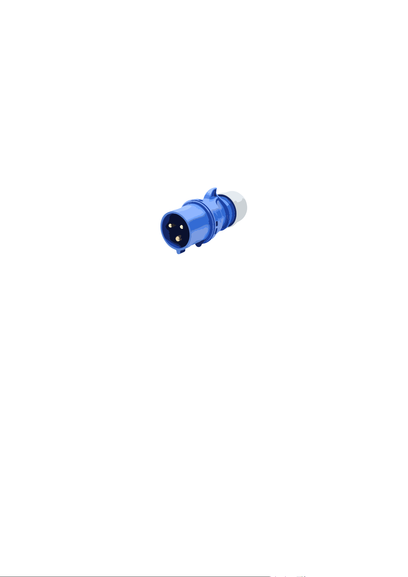
SAFETY WARNING
Connection to the mains supply must be either via an industrial plug, such as a “C Form”
connector of the type shown below:
or permanent
ly connected to the mains supply.
Where the amplifier is mounted in a rack and permanently connected to the mains, then the
rack should be installed with a readily accessible connector or an ALL POLE circuit breaker
with 3mm breaking distances.
This unit is supplied with a 3-wire power cord.
For safety reasons,
THE EARTH LEAD SHOULD NOT BE DISCONNECTED IN ANY CIRCUMSTANCE.
If ground loops are encountered consult the section on connecting your amplifier on page 14.
The wiring colours are:
230V AREAS: EARTH = GREEN AND YELLOW
N
EUTRAL = BLUE
L
IVE = BROWN
DO NOT USE THE UNIT IF THE ELECTRICAL POWER CORD IS FRAYED OR BROKEN. The
power supply cords should be routed so that they are not likely to be walked on or pinched by
items placed upon or against them, paying particular attention to cords and plugs and the
point where they exit from the appliance.
ALWAYS OPERATE THE UNIT WITH THE AC GROUND WIRE CONNECTED TO THE ELECTRICAL
SYSTEM GROUND. Precautions should be taken so that the means of grounding of a piece of
equipment is not defeated.
DO NOT REMOVE THE LID. Removing the lid will expose you to potentially dangerous
voltages. There are no user serviceable parts inside.

Delta Series D40/80/100 DSP Operating Instructions Page 11
ESD strikes to the unit’s front panel that are in excess of 4000 vo
lts may cause disturbance to
the status LEDs on the unit. This will not affect audio performance and will be corrected on
the next power up cycle.
Terminals marked with the
symbol are HAZARDOUS LIVE — external wiring connected to
these terminals requires installation by an INSTRUCTED PERSON or the use of ready-made
leads or cords.

Page 12 Delta Series D40/80/100 DSP Operating Instructions
Installing Your Amplifier: Mechanical Considerations
To ensure that this equipment performs to specification, it should be mounted in a suitable
rack or enclosure as described below. Like all high power amplifiers, it should be kept away
from other equipment which is sensitive to magnetic fields. Also, this amplifier may suffer a
substantial reduction in performance if it is subjected to, or mounted close to equipment
which radiates high RF fields.
Warning: To prevent injury, this apparatus must be securely attached to the rack in
accordance with the installation instructions
When mounting the amplifier in a rack or enclosure:
Be aware that…
THE FRONT PANEL IS NOT CAPABLE OF SUPPORTING THE UNIT ON ITS OWN.
Make sure that the rear of the unit is adequately supported. The brackets which are supplied
fit standard 19 inch (483mm) rack mounting systems.
ENSURE THERE IS ADEQUATE VENTILATION.
The cooling fans suck cool air in through the front and blow hot air out at the rear of the unit
through the ventilating grills. The front and rear of the amplifier should have free exposure to
the air (i.e. in a rack leave the front & rear doors off), with 2cm air gap at the sides.
IF AIR IS NOT ALLOWED TO ESCAPE FROM THE REAR, OVER-HEATING WILL OCCUR.
Take care when mounting other equipment in the same rack.
Make sure that the rack unit has a separate earth connection (technical earth).
Please also see the notes regarding maintenance on page 69.
Installing Your Amplifier: RF Emissions
The high frequency resonant converters in the Delta Series amplifiers have been designed to
have very low radio frequency (RF) emissions; however even these low level emissions can
cause interference with other equipment.
In order for this to be minimised, the amplifier should be mounted in a metal rack enclosure,
which should have a separate (technical) Earth. Alternatively, a separate earth should be
attached to the amplifier at the rear rack mounting bracket.

Delta Series D40/80/100 DSP Operating Instructions Page 13
About Your Amplifier: Dynamic Amplifier Performance Measurements
The Delta Series DSP amplifiers are the very latest examples of a ‘dynamic amplifier’. This
new ‘breed’ of power amplifiers provide very high peak power levels in a much smaller, and
lighter, package than previously possible with conventional designs.
They are designed specifically for today’s high power audio installations, which use multiple
speakers with electronic crossovers or speaker controllers. These systems can handle very
high transient signals that far exceed their RMS power rating. The Delta Series amplifiers
have been designed to match this requirement and can deliver huge levels of power for short
durations.
In order to protect themselves and the loudspeakers that they are driving, continuous signals
such as sine waves, are automatically detected and reduced (ramped down) to a safe level.
When trying to measure the power output however, continuous signals will give totally
incorrect results. A dynamic signal, such as a tone burst, should be used and the levels
measured by monitoring the waveform on an oscilloscope. The power envelope can then be
accurately measured.
Our power output figures are measured using signals with known Crest Factors and are
quoted at the rear of this manual on page 70 and on our website.
Please refer to the technical area of our website for further information — here you can
download a set of Crest Factor tailored audio samples to allow you to compare our
specifications with any other amplifier.
Page 14 Delta Series D40/80/100 DSP Operating Instructions
Connecting To Your Amplifier: Line Inputs and Outputs
The inputs are made via 3-pin XLR connectors, which are electronically balanced and should
be connected via a high grade twin core screened cable, as follows:
PIN1: Screen (see note below)
PIN2: Hot (signal +)
PIN3: Cold (signal -)
The amplifier is designed to operate with fully balanced equipment and ground loops or loss
of performance may be experienced if connected to unbalanced sources. If it is unavoidable
however, the following wiring should be used. The cable should still be twin core plus screen.
PIN1: Screen - connected to the chassis of the unbalanced equipment - or left disconnected
at the unbalanced end.
PIN2: Hot (signal +)
PIN3: Cold (ground 0V)
NOTE: This amplifier is wired to the latest industry recommendations. PIN1 is connected
directly to the chassis/mains earth. If ground loops (mains hum) are encountered remove the
screen connection from the other end of the cable and leave it open circuit. If problems
persist, consult your dealer/supplier.
DO NOT TAMPER WITH OR ALTER ANY GROUND (EARTH) CONNECTIONS INSIDE THE
AMPLIFIER.
For bridged operation input should be made to channel A (or C) only and the channels set for
bridged mode for the appropriate pair of channels. Please see page 44 for details of how to
do this.
Outputs are also made via 3-pin XLR connectors wired as follows:
PIN1: Screen (see note above)
PIN2: Hot (signal +)
PIN3: Cold (signal -)
Note that the rear panel outputs are electronical
ly balanced and so are not galvanically
(electrically) isolated. Front panel outputs are transformer balanced and so are isolated.
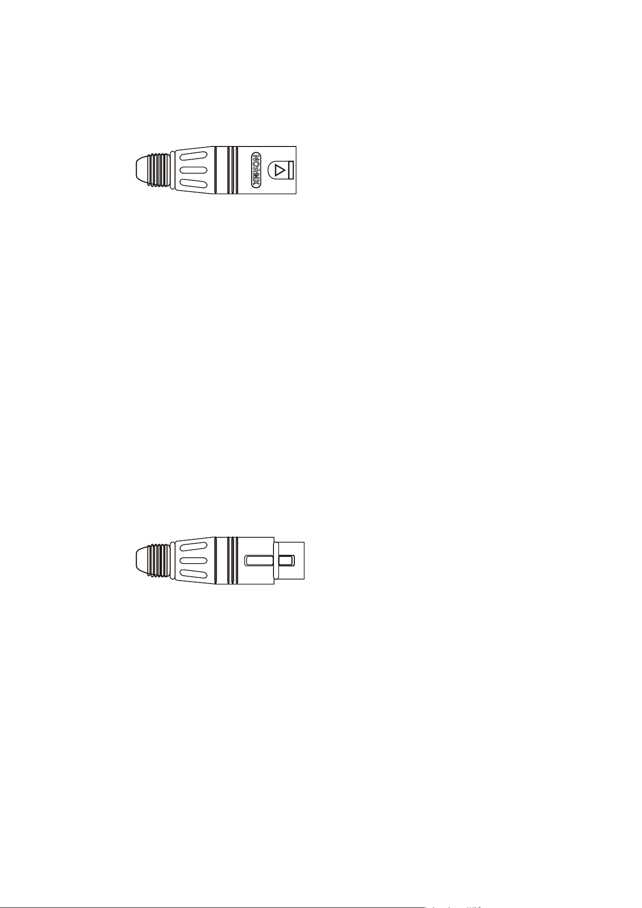
XLR
MALE
XLR
FEMALE

Delta Series D40/80/100 DSP Operating Instructions Page 15
Connecting To Your Amplifier: Speaker Outputs
The speaker outputs are via Neutrik Speakon connectors. 2 pole (NL2FC) or 4 pole (NL4FC)
connectors can be used.
Pin 1+: Hot
Pin 1-: Cold
Additionally, Channel 1 Speakon connector carries Channel B2output on Pins +2 & -2 to allow
easy bi-amping or bridged operation using a single NL4 connector. Similarly, Channel 3’s
Speakon connector also carries Channel 4 output.
Output Connector 1
Pin 2+: Hot Ch. 2
Pin 2-: Cold Ch. 2
Output Connector 3
Pin 2+: Hot Ch. 4
Pin 2-: Cold Ch. 4
For bi-amped operation, connect as above.
There must be no shared connections between channels.
Negative output terminals must not be joined together as they are not both at ground
potential. Connecting them together will damage the amplifier and void the warranty!
As the currents involved are very high, and to ensure best performance, the speaker cables
should be kept as short as possible and conform to the following minimum requirements:
Delta 40 DSP, 11A into 4 Ohm speaker loads
Delta 80 DSP, 14A into 4 Ohm speaker loads
Delta 100 DSP, 20A into 4 Ohm speaker loads
When operating the amplifier into loads of less than 4 Ohms, be aware that the current
capacity of the speaker cables will need to be increased above the values quoted here.
Do not connect the inputs/outputs to any other voltage source such as a battery, mains source
or power supply, regardless of whether the amplifier is turned on or off.
Do not run the output of any amplifier channel back into another channel’s input and do not
parallel or series-connect an amplifier output with any other amplifier output.
SPEAKON
NL2 & NL4

Page 16 Delta Series D40/80/100 DSP Operating Instructions
Connecting To Your Amplifier: Bridged (Mono) Operation
Pairs of ch
annels may be independently bridged — channel pair 1+2, and/or channel pair 3+4.
The method is the same for both channel pairs:
Select the required bridged mode through the front panel MENU system (see page 44 for
more information).
Use Channel 1 or 3’s Output Speakon connector and connect as follows:
Pin 2+: Hot
Pin 1-: Cold
When operating in bridged mode, the minimum impedances are doubled.
The minimum load in bridged mode is 4 ohms.
Delta Series D40/80/100 DSP Operating Instructions Page 17
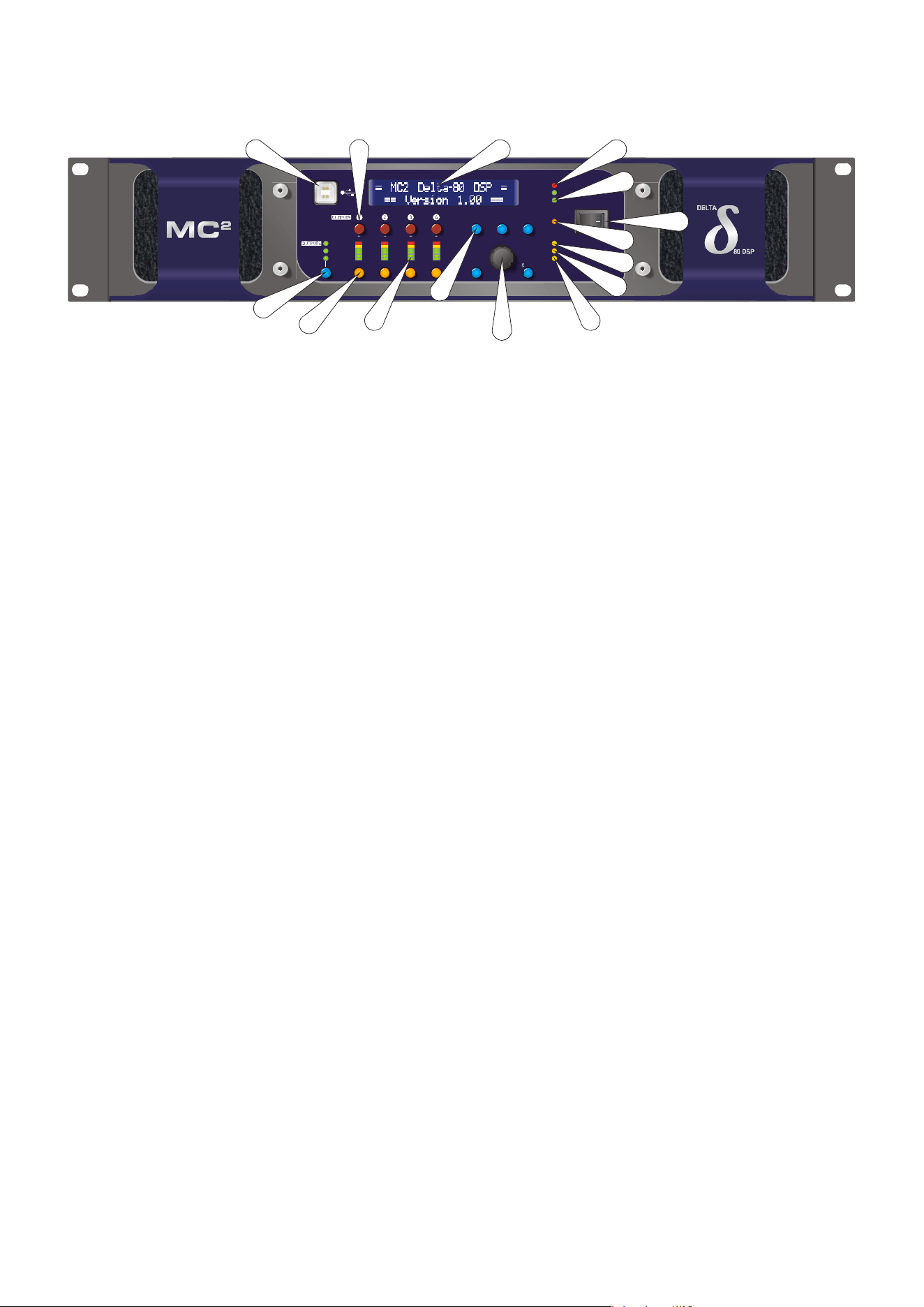
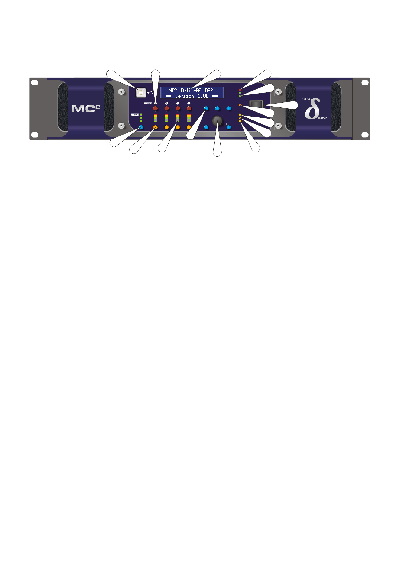
Operating Your Amplifier: Front Panel Controls and Indicators
1: USB Type “B”: Connect to a computer for remote control — a driver will be required.
Please see the section on remote control starting on page 51.
2: MUTE keys: This will mute the respective input or output channel according to the current
setting of the bank control selection (#14).
3: 2 x 24 LCD: By default this will display preset names and is used to show all parameter
information. The LCD contrast and backlight brightness can be adjusted in the System Sub-
Menu — see page 48 for details. If the LCD backlight is flashing, it is being remotely identified
by software.
4: PROTECTION LED: If a condition exists, either internally or externally, that could cause
damage to either the amplifier or the speakers, the protection circuit will disengage the
outputs and this LED will illuminate/flash.
Typical conditions that could cause the protection to be triggered include very high frequency
or subsonic input signals, DC in the inputs, short-circuited outputs, or internal high
temperatures.
The protection circuit can affect all channels or a ‘channel pair’ depending on the type of
fault. This is indicated by the combination of Protection LED illuminating and a corresponding
message on the LCD. In this way, it is possible for two channels (a channel pair) to remain
functioning even though a fault has caused the other channel pair to mute. A channel pair
would be 1+2 or 3+4.
Temperature related faults will reset automatically if the unit has cooled sufficiently. Output
short circuits will require manual reset after clearing the fault (switching off at the mains
switch and then on again after a few seconds). Short circuits on either channel of a channel
pair will only affect that channel pair.
5: BRIDGE pair LEDs: The channel pair LED will illuminate if these channels have been
switched into bridged (mono) mode. See page 14 for details of how to connect your speaker to
a bridged channel pair, and page 44 for how to enable bridge mode.
6: Power Switch: This double pole switch turns the amplifier fully off and isolates it from the
mains supply.
7: STBY LED: The power amplifiers in the Delta 80 can be powered down leaving just the DSP
active. Apart from the obvious power savings to be made, there may be circumstances when
only the DSP is required, such as utilizing it for braking analogue audio channels onto a Dante
network. This LED illuminates when the power amplifier sections are turned OFF.
HINT: The amplifier can be brought out of standby by holding ENTER and QUIT at power-up.
MENU
IN A-D
AUX 5-8
MUTE
EDI T
BACK
QUIT ENTER
PROTECTION
BRIDGE 1+2
BRIDGE 3+4
REMOTE
L+ 4
LI M
6
12
18
24
CLIP
0
6
12
18
24
G.R.
1
2
4
8
16
ADJUST
NETWORK AUDIO
ABCD
5678
BANK
DELTA SERIES DSP
PROCESSING POWER AMPLIFIER
L+4
LIM
6
12
18
24
L+ 4
LI M
6
12
18
24
DIGITAL IN
STBY
4
5
6
7
9
12
14
13
15
21
10
3
11
8
Page 18 Delta Series D40/80/100 DSP Operating Instructions
8:
REMOTE LED: This will flash when the unit is being addressed under remote control.
9: DIGITAL IN LED: This illuminates if either AES input is switched in (replacing the
respective analogue input channel) and will flash if there is a loss of lock on either input.
Note that this does not mean AES is actually routed to the amplifier’s DSP, only that a rear
panel socket is set to receive an AES stereo signal.
10: NETWORK AUDIO LED: This will illuminate when an audio network connection is
correctly made to the amplifier. Note that this does not mean that any network audio
channels are actually routed to the amplifier’s DSP, only that the connection is available.
11/12: Rotary encoder and navigation keys: MENU is always the way under the bonnet of the
amplifier, and then BACK and NEXT to choose the Sub-Menu and ENTER to select the choice.
These controls are also used when editing DSP audio parameters, accessed via the EDIT
keys.
13: Signal meters: Depending on the current bank selected (#14), these will be showing input
levels pre-DSP, output levels for the power amp channels, or output levels of the auxiliary
channels.
14: EDIT keys: First press on an EDIT key will show the gain for the selected channel within
its respective BANK. Second press will display the last edited parameter — see pages 28 to 30
for more info on full real-time editing of input and output parameters.
15: BANK Select key and LEDs: This key will cycle through three banks: inputs A-D, power
amp outputs 1-4 or auxiliary outputs 5-8, for both meter displays, mute functions and during
editing. Bank select will default to showing power amp outputs on meters and mutes after 20
seconds of inactivity.
MENU
IN A-D
AUX 5-8
MUTE
EDI T
BACK
QUIT ENTER
PROTECTION
BRIDGE 1+2
BRIDGE 3+4
REMOTE
L+ 4
LI M
6
12
18
24
CLIP
0
6
12
18
24
G.R.
1
2
4
8
16
ADJUST
NETWORK AUDIO
ABCD
5678
BANK
DELTA SERIES DSP
PROCESSING POWER AMPLIFIER
L+4
LIM
6
12
18
24
L+ 4
LI M
6
12
18
24
DIGITAL IN
STBY
4
5
6
7
9
12
14
13
15
21
10
3
11
8
Delta Series D40/80/100 DSP Operating Instructions Page 19
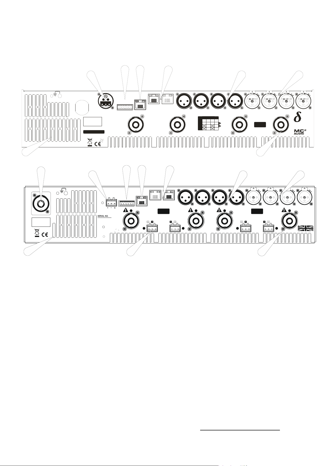
Operating Your Amplifier: Rear Panel Sockets and Switches
Delta DSP80 and DSP100 rear panel
Delta DSP40 rear panel
1: Fan outlet: The variable speed fans suck air in through the front vents and out through the
back of the amplifier. Please see maintenance on page 69 for recommendations on how to
clean this and the front foam sections.
2: Channel A output Speakon socket: Normal output is on pins 1+ hot, 1- cold. Channel B’s
output is also wired to this socket to enable a single NL4 to provide both channels and to
facilitate easier wiring in bridged mode. Channel B is wired pins 2+ hot, 2- cold. Similarly
channel C’s output Speakon socket carries Channel D’s output. Check the table on the rear
panel for details.
3: Input XLR sockets: Connect signal inputs to these sockets, wired pin 2 hot, 3 cold, 1
ground. For sensitivity and impedance of these inputs, please see the specifications on page
70. Inputs
C & D may also be switched to AES digital inputs, each carry
ing a stereo AES
st
ream — channels A&B on socket C, channels C & D on socket D. This arrangement allo
ws
an
analogue stereo source to remain connected to sockets A & B for fallback
purposes. To
sel
ect AES inputs please see the section on page 36.
4: Auxiliary output XLR sockets: These carry the four additional channels of separate DSP
processing — they are NOT just link outputs or a copy of the power amplifier channel’s
processed audio — they are fully independent.
5: Audio network connections
1
: Four additional inputs can be added to the available input
matrix via the optional Dante network card. This will also add four network audio outputs,
which can be chosen (in banks of four) from a variety of processing points within the
1
The audio network card is an option and may not be fitted to your amplifier.
All ven t s on fr on t an d r ear of u n i t mu st n ot b e ob st r u cted.
Tous les passages sur avant et arrière de l'unité ne doivent pas être obstrués.
SERIAL NO.
CH. D
OUT
CH. C
OUT
CH. B
OUT
CH. A
OUT
Cl ass 3 W iring
on Ou t p u t s
BRG
OUTPUT
CONNECTIONS
1+
1-
2+
2-
D+ C+ B + A+
D- C - B- A-
D-
B+
B-
DCBA
D+
1 - AUDIO NETWORK - 2CON TROLGPIO PORT
1 23456
AUX 4AUX 3AUX 2AUX 1
1: 0V
2/3: I N 1& 2
4/5: OUT 1& 2
6: +5V
RS485
DES IGN ED AND
MANUFACTURED
IN ENGL AND BY
SERIES
A
E
S
A
&
B
A
E
S
C
&
D
3
2
1
4
5
67
8
All vents on front and rear of unit must not be obstructed.
Tous les p assag es sur avant et ar r i ère de l'u ni té ne doi vent p as êtr e obstr ués.
OUTPUT
Class 3 Wiring
on Ou tp u ts
1 - AUDIO N ETWORK - 2CON TROLGPIO PORT
1234 56
AUX 4 AUX 3 AUX 2 AUX 1
1: 0V
2/3: I N 1& 2
4/5: OUT 1& 2
6: +5V
RS485
A
E
S
A
&
B
A
E
S
C
&
D
OUTPUTOUTPUTOUTPUT PIN : CONN ECTION
1+/1-: OUT 4+/4-
2+/2-: N C
MAINS SUPPLY
PIN: CONNECTION
1+/1-: OUT 3+/3-
2+/2-: OUT 4+/4-
1-/2+: BRIDGE -/+
PIN: CONNECTION
1+/1-: OUT 2+/2-
2+/2-: N C
PIN: CONNECTION
1+/1-: OUT 1+/1-
2+/2-: OUT 2+/2-
1-/2+: BRIDGE -/+
Class 3 Wiring
on Ou tp u ts
SPEAKE R BACKUP IN PUTS
(see manual for details of operation)
SPEAKER BACKUP INPUTS
(see manual for details of operation)
NC NC NCNC
DES IGN ED AND
MANUF ACTURED
IN ENGLAND
by
XTA Electronics Ltd.
and
MC Au d i o
2
1
2
34
5
67
8
9
10

Page 20 Delta Series D40/80/100 DSP Operating Instructions
amplifier’s DSP structure. For more on this feature see the bl
ock diagram on page 22 and
set-up information from page 42.
6: Ethernet control port: Your amplifier may be remotely controlled by connecting it to a
computer via this standard Ethernet port connection. Please see the section starting on page
51 for how to use this feature. HINT: You can quickly check the amplifier’s IP address by
pressing ENTER + NEXT.
7: GPIO Port: Your amplifier has a pair of general purpose logic level input and outputs that
can be configured to recall memories, put the amplifier in standby, mute and control levels,
and also provide feedback about status. Please see the section on page 59 for more details.
8: RS485 Port: Your amplifier may also be controlled via an RS485 connection, and this port
may also be used to relay control data from the Ethernet port or the front panel USB port to
connect to further devices. Please see the remote control section on page 51 for more
information.
9: PowerCon mains inlet: Depending on your model, this will either be a fixed mains cable, or
a 20A or 32A connector.
10: Speaker Backup Inputs (DSP40 only): These sockets can be used to connect a backup
amplifier that will automatically be switched in circuit should the main amplifier lose power,
or go into “Protect”. See Appendix III on page 86 for a further information on how to use this
feature.

Delta Series D40/80/100 DSP Operating Instructions Page 21
Operating Your Amplifier: Initial Set-up and Switching On
Please read all documentation before operating your amplifier and retain all documentation
for future reference.
Do not spill water or other liquids into or on the unit and do not operate your amplifier while
standing in liquid.
Do not block fan intake or rear ventilation outlets or operate the unit in an environment that
could impede the free flow of air around the unit.
If your amplifier is used in an extremely dusty or smoky environment, it should be cleaned of
any collected debris at regular intervals. Please also see the notes regarding maintenance on
page 69.
It is important that the power output of your amplifier is matched to the power handling
capacity of your loudspeaker. If not, damage to the loudspeaker could occur.
Switching On…
The first time you switch it
on, your amplifier will start-up as a four analogue inputs to four
output system, with no EQ or limiting (apart from self-protective limiters) in place. The aux
outputs will “mirror” the analogue inputs (and so initially act just like “link” outputs, again
with no EQ or limiting in place).
The following section explains the DSP and audio features of the amplifier — please read this
carefully as the routing options are very comprehensive!
Page 22 Delta Series D40/80/100 DSP Operating Instructions
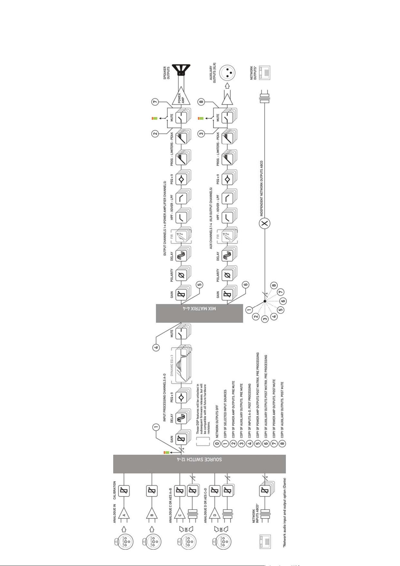
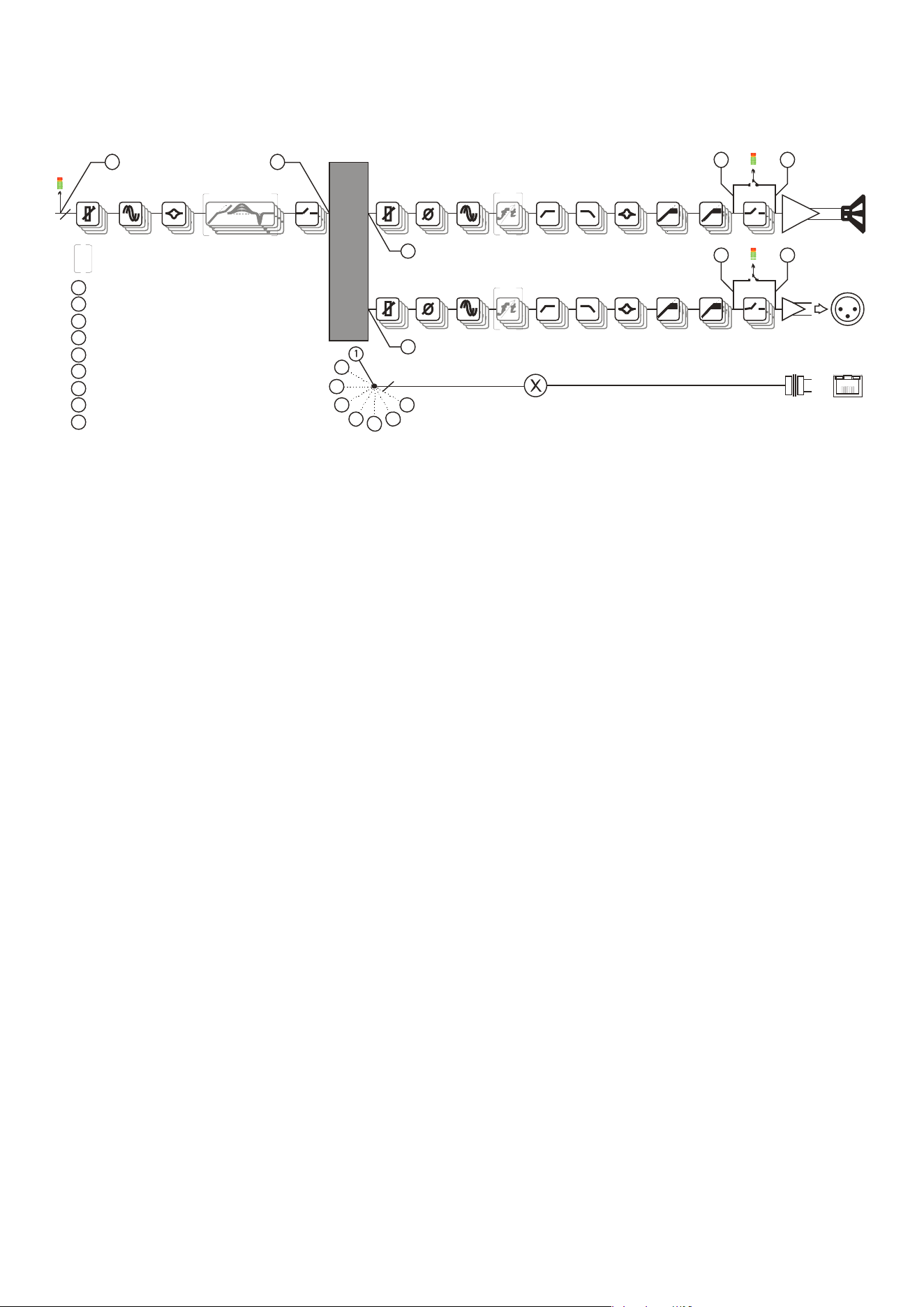
Inside Your Amplifier: DSP Layout, Configurations and Routing
Delta Series D40/80/100 DSP Operating Instructions Page 23
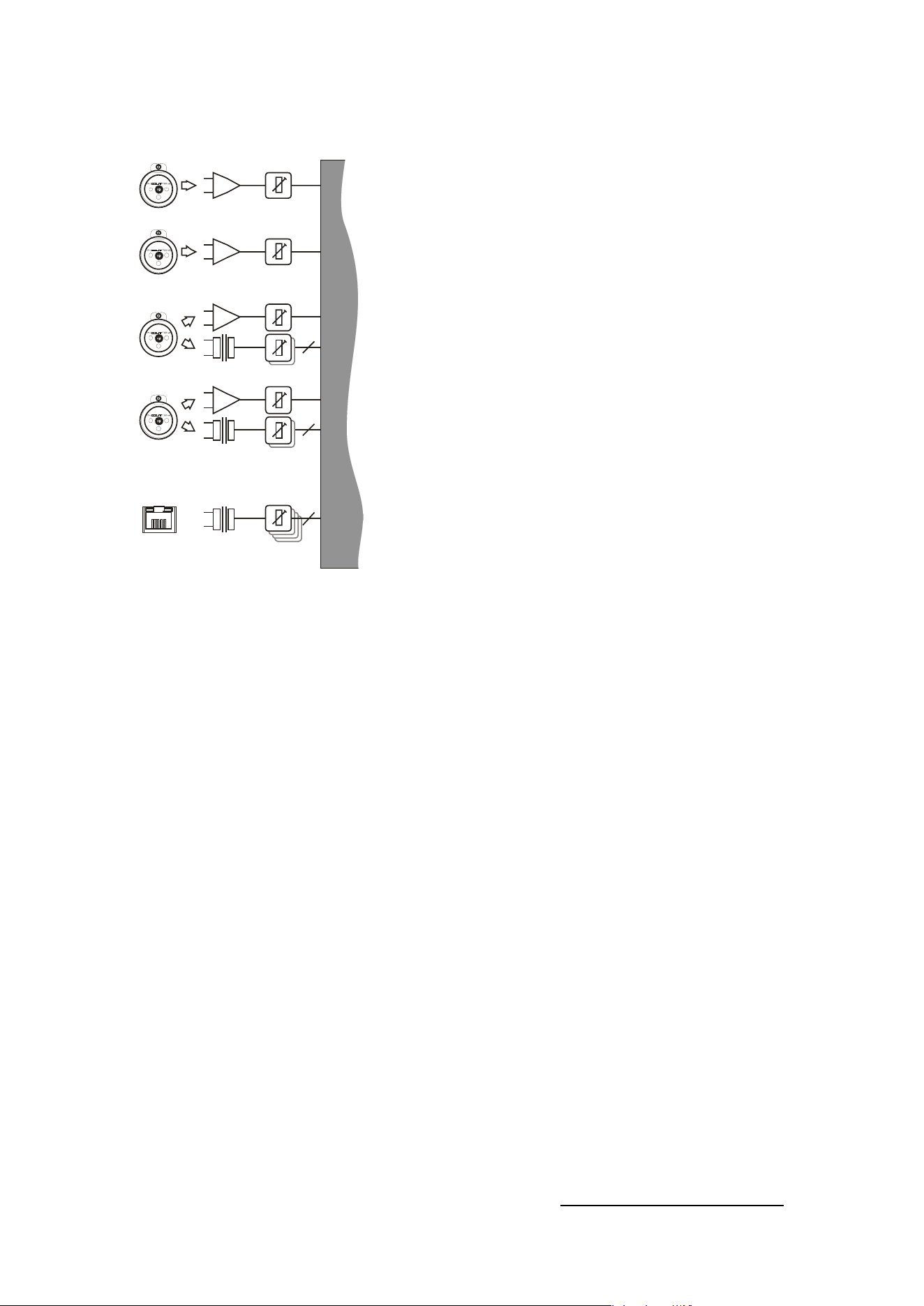
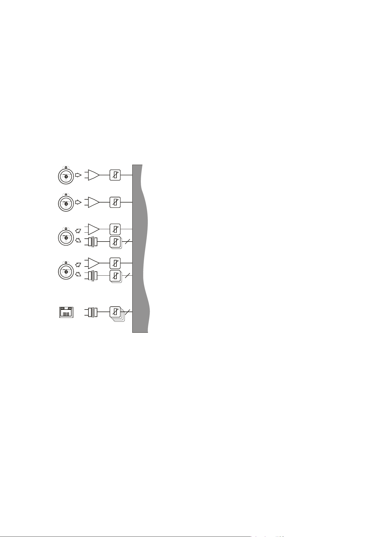
Source Choices and Selection
Your amplifier can source audio from analogue, AES
digital, or network locations (if a network card is
fitted).
Analogue and AES digital audio are standard, and
arranged so that AES digital audio can be chosen in
pairs of channels to replace either analogue inputs
A&B together or analogue inputs C&D together, or all
four channels.
Physical input of AES for channels A&B is swapped to
the input XLR for channel C and the AES input for
channels C&D is on the XLR socket for channel D.
In this way, a pair of analogue inputs can remain
connected to channels A&B and a digital stream of
the same audio can be connected to input C, with
fallover from one to the other possible without
repatching.
Assuming the network audio option is also fitted, four
additional digital sources will then be available.
In total, 8 sources can be made available at any one time — four analogue and four digital.
This affects the choices that can be made for routing to the inputs of the DSP channels.
The rules are as follows:
Analogue A and B is available at all time
s;
If
AES A&B is selected, Analogue C cannot be used (shares XLR C)
;
If AES C&D is
selected, Analogue D cannot be used (shares XLR D)
;
If AES A&
B is chosen, Dante A&B cannot be used (shares SRC
2
One);
If AES C&D is
chosen, Dante C&D cannot be used (shares SRC Two)
;
Source sel
ection is therefore affected by the selection of AES inputs, which then controls the
choice of input source selections on offer to any input processing channel.
Please see page 35 for further info on using the AES and Input source selection menu options,
and how to configure fallover options.
2
SRC: Sample rate converter — input sample rate can be from 44.1kHz up to 192kHz
ANALOGUE IN CALIBRATION
NETWORK
INPUTS ABCD*
A
B
C
D
ANALOGUE C OR AES A+B
ANALOGUE D OR AES C+D
OR
OR
2
4
2
SOU RCE SWITCH 1 2-4
*Network audio input and output option (Dante)
Page 24 Delta Series D40/80/100 DSP Operating Instructions
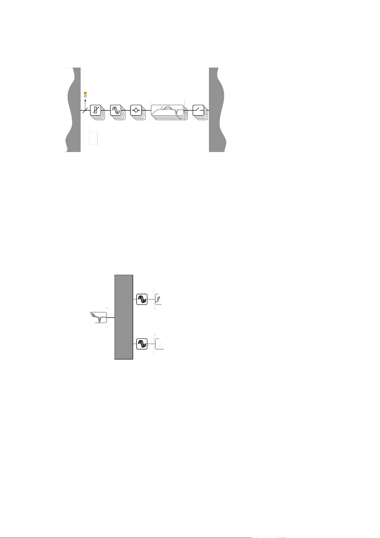
Input Processing Channels
Your amplifier has four
input channels of
processing that can be fed
from a variety of sources.
These four channels in
turn, feed a mix matrix for
routing to the power
amplifier processing
channels and the auxiliary
output processing
channels.
Each input processing channel consists of the following sections:
- Input gain contro
l
- Input delay time
- Input parametric EQ bands 1 through 9
The dyn
amic EQ sections will be added in a future firmware update. For more information on
adjusting input processing parameters, please see the section beginning on page 28.
Mix Matrix Section
The mix matrix allows four independent mixes
to be set up for the power amplifier channels
and the auxiliary output channels.
These can be either “Boolean” in design (so just
A+B+C etc.) or a full mix matrix mode can be
used to allow four continuously variable
“sends” from the four input processing
channels to be combined.
There are also a variety of templates to act as starting points for crossover duties, where
useful crossover (high and low pass) frequencies are automatically assigned to groups of
outputs, dependant on the format used. For more information on adjusting the mix matrix,
please see the output editing section on page 34. Note that the mix matrix will only be
available if it has been selected as part of the output/auxiliary configurations — see page 42 to
change this.
FIRDELAY
DYNAMIC EQ x 3
MIX MATRIX 4-4
FIRDELAY
f t
MIX MATRIX 4-4
SOURCE SWITCH 12-4
PEQ x 9DELAY DYNAMIC EQ x 3GAIN
4
INP UT PRO CES S ING CHANNELS A- D
These DSP features will be unlocked in
subsequent f i rmw are re l ea ses, but w i l l
be compatible with all future hardware
rev i si ons.
MUTE
Delta Series D40/80/100 DSP Operating Instructions Page 25
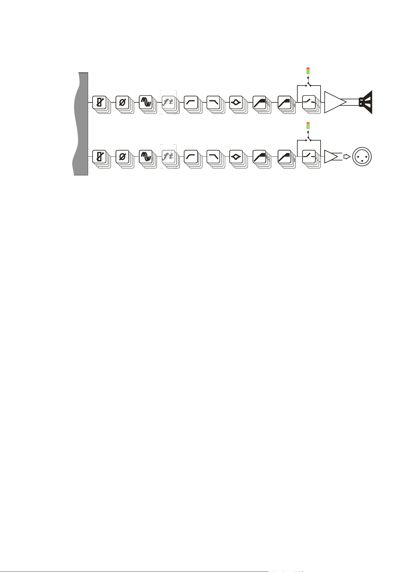
Power Amplifier and Auxiliary Output Processing Channels
MIX MATRIX 4-4
OUTP UT CH ANNELS 1- 4 ( P O WER A M P LI FI ER CHANNELS )
PROG. - LIMITERS - PEAK
MUTE
AU X CHANNELS 1- 4 ( XLR OUTP UT CHANNELS )
PROG. - LIMITERS - PEAK
MUTE
POWER
AMP
AUXILIARY
OUTPUTS [XLR]
SPEAKER
OUTPUTS
PEQ x 9
FIRDELA Y HP F - XO VER - LP F
GAIN
PEQ x 9FIRDELA Y HP F - XO VER - LP FGAIN
POLARITY
POLARITY
There are eight identical channe
ls of output processing in your amplifier: four dedicated to
the power amplifier channels, and a further four that are connected to the auxiliary XLR
outputs on the amplifier, providing analogue feeds to other equipment.
Each output processing channel consists of the following sections:
- Output dela
y time
- High and
low pass crossover filters (up to 48dB/Oct.)
- Output parametric EQ bands 1 through 9
- Output gain co
ntrol
- Program (RM
S) li
miter
- Peak limiter
FIR
filtering capabilities are available from firmware version 1.24 onwards. FIR filtering is
not user adjustable and is part of OEM presets only. For more information on adjusting
output processing parameters, please see the section beginning on page 30.
Page 26 Delta Series D40/80/100 DSP Operating Instructions
Independent Network Audio Outputs
If
your amplifier has a network audio card fitted (Dante) then, as well as being able to route
four channels of audio from the network, it is possible to route four channels of audio back
onto the network.
This feature is primarily intended for use with the Delta NON-DSP models, which may also be
fitted with a network audio interface, allowing them to utilise the additional processing
channels in your Delta DSP model via connection with a single Ethernet cable.
Working like this, the network audio outputs would be routed directly from end of the
auxiliary output processing, so that they are just a copy of the signals available at the Aux XLR
outputs 1-4 (choice #1 in the above diagram).
However, there are other circumstances where it might be more useful to route these outputs
from elsewhere within the DSP processing. For example, if the network outputs are being
used to also “break-in” analogue or AES channels, for use with other amplifiers, it might be
more applicable to route the audio from the outputs of
input
processing channels (choice #5).
If it’s required for the network outputs to break in channels that are not being used by the
local processing, this can also be achieved by using the outputs of the mix matrix which feed
the auxiliary output processing (choice #3).
Alternately, the mixes being used by the power amp processing can be selected (choice #4)
and finally, the pre-mute final output of the auxiliary channels’ processing may be selected
(choice 2) to prevent muting the local aux outputs from muting the network feeds.
Note that these routing selections work on a “x4” basis — all four network output feeds are
selected from one of the above choices as a group — they cannot be individually assigned to
different points.
For more information on selecting the network audio output routing, please see the section
on page 39.
OU TP UT CHA NNELS 1- 4 ( P OWER A M P LI FI ER CHANNELS )
PROG. - LIMITERS - PEAK
MUTEPEQ x 9DELAY DYNA M I C EQ x 3GAIN
INDEPENDENT NETWORK OUTPUTS ABCD
NETWORK
OUTPUTS*
MIX MATRI X 4-4
4
AU X CHA NNELS 1- 4 ( XLR O UTP U T CHA NNELS )
PROG. - LIMITERS - PEAK
MUTE
I NP UT P RO CES S I NG CHANNELS A - D
4
6
3 8
5
2
3
4
5
4
NETWORK OUTPUTS OFF
1
COP Y OF S ELECTED I NP U T S OU R CES
2
COPY OF POWER AMP OUTPUTS, PRE MUTE
3
COP Y OF A UXI LI A R Y OU TP U TS , P R E M U TE
4
COPY OF INPUTS A-D, POST PROCESSING
These DSP f eatures w i l l be unlocked i n
subs equent fi rmw are rel ea s es, but w i l l
be compatible with all future hardware
rev i si ons .
POWER
AMP
AUXILIARY
OUTPUTS [XLR]
SPEAKER
OUTPUTS
MUTE
PEQ x 9FIRDELAY HP F - XO VER - LP FGAIN
PEQ x 9FIRDELAY HP F - XO VER - LP FGAIN
POLARITY
POLARITY
5
COPY OF POWER AMP OUTPUTS POST MATRIX, PRE PROCESSING
6
COPY OF AUXILIARY OUTPUTS POST MATRIX, PRE PROCESSING
7
COPY OF POWER AMP OUTPUTS, POST MUTE
8
COPY O F AUXILIARY OUTPUTS, POST M UTE
0
6
7
8
2 7
1
Delta Series D40/80/100 DSP Operating Instructions Page 27
Operating Your Amplifier: Directly Editing Audio Parameters
Overview
Editing all audio parameters is available from the front panel of your amplifier using a
combination of the select BANK key, reassignable EDIT keys, and the BACK/NEXT/ENTER
navigation controls.
First, make sure the correct bank of channels is selected — either inputs A-D, amplifier
outputs 1-4 or auxiliary outputs 5-8 by pressing the BANK key.
Next, press the EDIT key that corresponds to the channel to be adjusted. The EDIT key will
illuminate, and the gain will always be displayed as the first parameter.
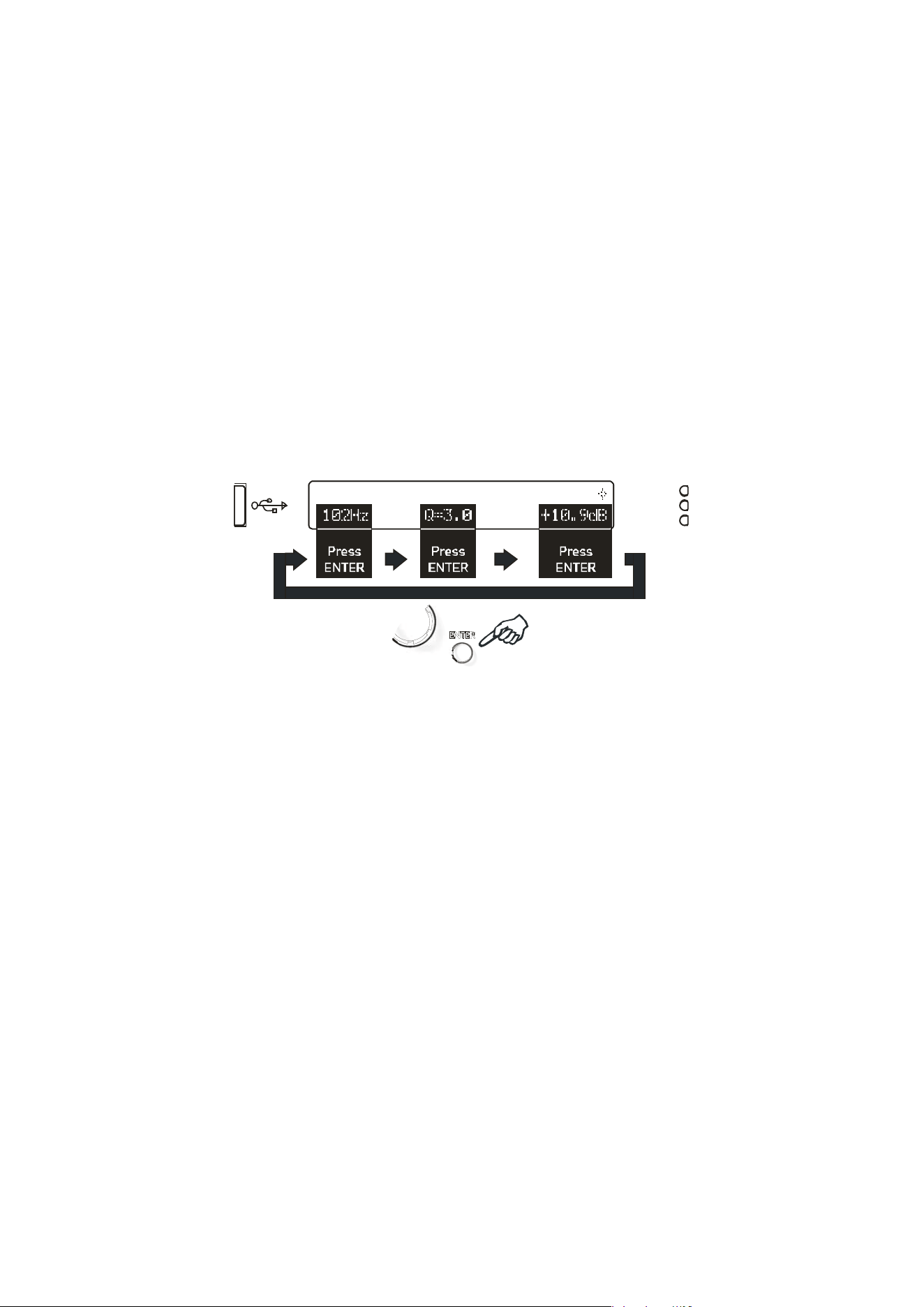
To choose another parameter, use BACK and NEXT to scroll through the available choices.
If there are multiple parameters grouped on a single screen (such as parametric EQ
frequency, ‘Q’ and gain) move between these using the ENTER key.
InpA DeskLeft PEQ:1
102Hz Q=3.0 +10.9dB
P
ress
ENTER
Press
ENTER
Press
EN
TER
Finall
y, use the rotary encoder to adjust the value of the parameter.
You can swap bank at any time by pressing the BANK key, and to quickly access the same
parameter on another channel (within a bank) double press on the required channel’s EDIT
key. If the same parameter doesn’t exist in a bank (such as no limiters on the input bank), the
gain screen will be shown.
A third press on the same EDIT key will exit editing and return to the current bank’s default
screen.
Hint: You can quickly check the same setting of any parameter on a bank of channels by
double pressing each EDIT key in turn — so to check each output’s polarity setting, just press
EDIT, press NEXT until Polarity is displayed, then press the next channel’s EDIT twice, and so
on.
Page 28 Delta Series D40/80/100 DSP Operating Instructions
Inp A Gain
Input Gain= 6.0dB
Inp A Delay
Delay = 500.00mS
Input Gain
Variable between
-40dB and +6dB in 0.1dB steps.
Input Delay
Max de
lay time is 650.000mS in 10uS steps. Swap to 1mS steps by pressing ENTER.
Units can be changed to read distance instead of time though the system sub-menu — see
page 48 for details.
Delta Series D40/80/100 DSP Operating Instructions Page 29
Inp A PEQ:1
100Hz Q=3.0 10.0dB
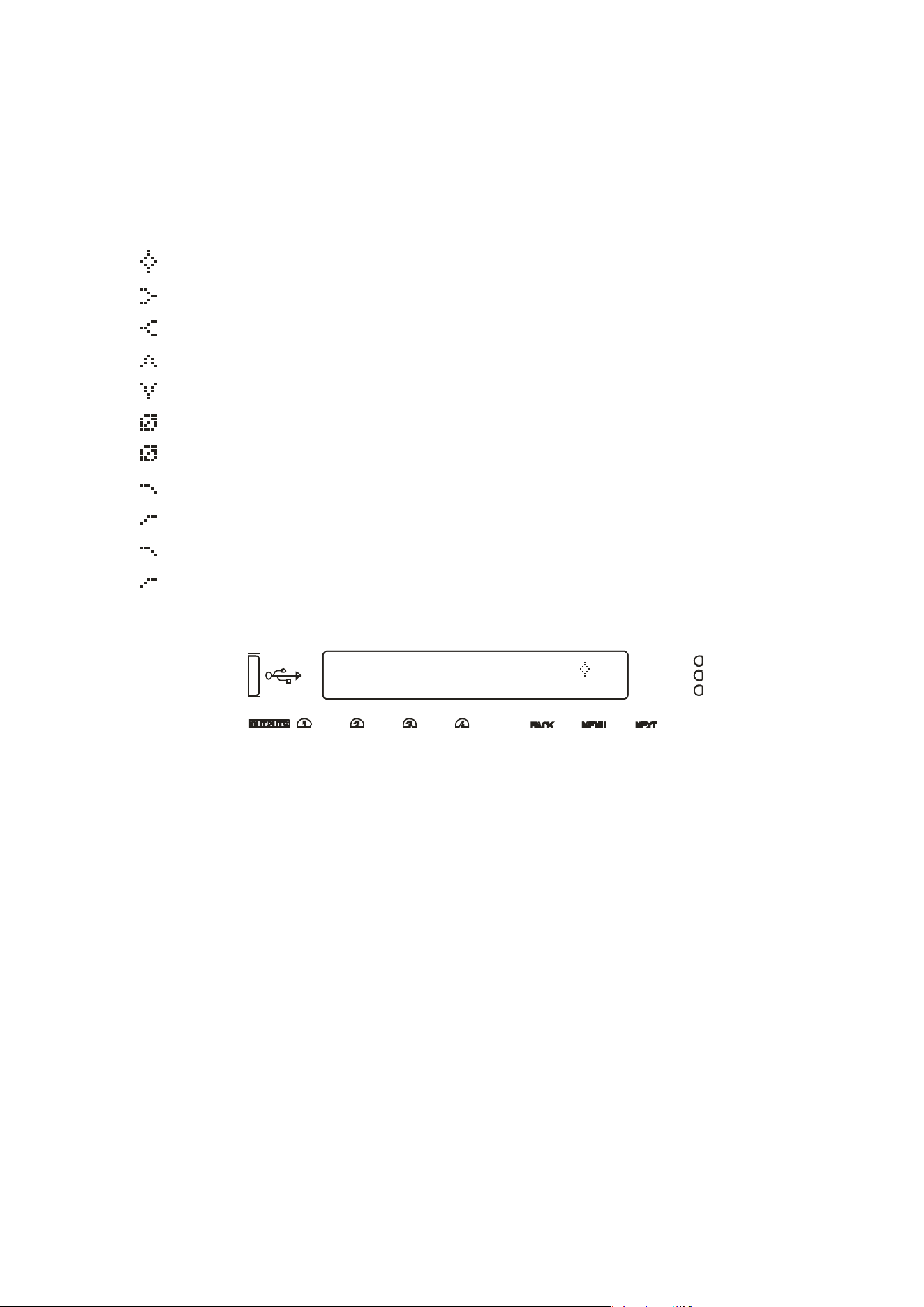
Input Parametric EQ Bands 1 through 8
All parametric bands cover a frequency range of 19.7Hz to 32kHz when in standard PEQ mode.
Some restrictions apply when other filter types are selected. Move between frequency, ‘Q’
and filter gain by pressing ENTER. Press and HOLD the ENTER key whilst pressing QUIT to
bypass a band and also access different filter types.
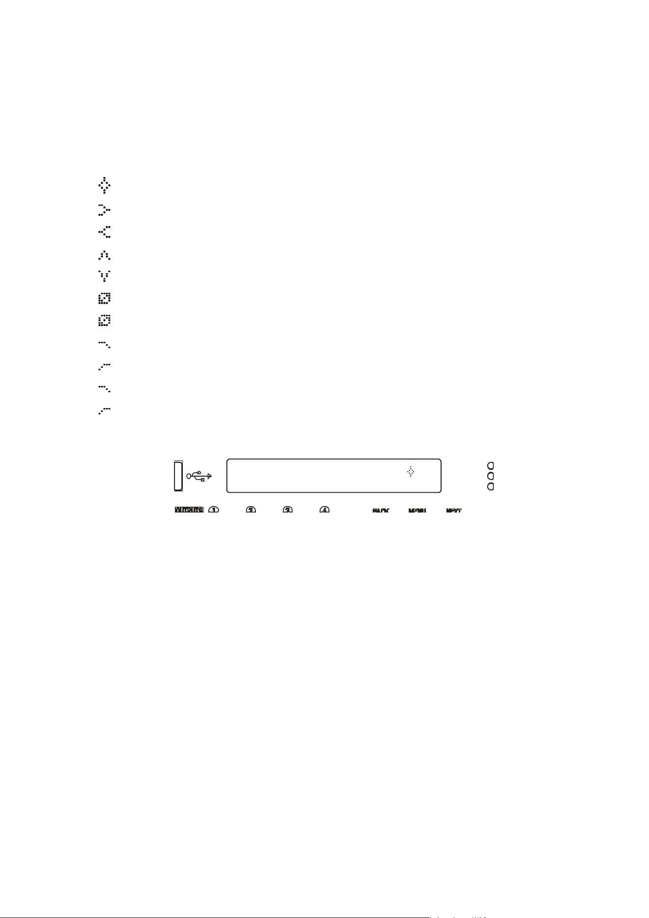
PEQ Parametric EQ
LSF Low Shelf
HSF High Shelf
BPS Band Pass
NOT Notch
APF All Pass
PHF Phase
LPF Low Pass VariQ
HPF High Pass VariQ
LPF Low Pass Elliptical
HPF High Pass Elliptical
A filter must be in Bypass before its type can
be changed. Once bypassed, the ENTER key will
allow access to the type list and this can be adjusted with the encoder, scrolling through the
types listed above.
Page 30 Delta Series D40/80/100 DSP Operating Instructions
Out 1 Output 1 Gain
Output Gain= +10.2dB
Out 1 Output 1 Polar.
Polarity = [ + ]
Out 1 Output 1 Delay
Delay = 650.0000mS
Output Gain
Variable between -40dB and +15dB in 0.1dB steps.
Output Polarity
Switch betwe
en normal [+] and inverted [-] polarity. Note that channel ganging is temporarily
disabled for polarity adjustments.
Output Delay
Max de
lay time is 650.000mS in 30nS steps. Swap to 1mS steps by pressing ENTER.
Units can be changed to read distance instead of time though the system sub-menu — see
page 48 for details.
Delta Series D40/80/100 DSP Operating Instructions Page 31
Out 1 Output 1 HPF
25.8Hz Linkw-Riley 24dB
Bypass PEQ’s 6 & 7
To Access 48dB Slopes
Out 1 Output 1 LPF
9k70Hz Linkw-Riley 24dB
Bypass PEQ’s 8 & 9
To Access 48dB Slopes
Output High Pass Filter
Set the high
pass filter frequency — a setting of “<10Hz” bypasses the filter. To change the
filter slope and type, press ENTER and then adjust with the encoder. Note that 48dB/Octave
filters will only be available if PEQ 6 & 7 are bypassed.
Parametric bands will remember their settings if bypassed and used in 48dB/Octave
crossover filters and these settings will be reinstated if a lower order filter type is
subsequently chosen (24dB/Octave or lower).
The message
will be shown if the bands aren’t already in bypass (or set to 0dB).
Output Low
Pass Filter
Set the low p
ass filter frequency — a setting of “>32kHz” bypasses the filter. To change the
filter slope and type, press ENTER and then adjust with the encoder. Note that 48dB/Octave
filters will only be available if PEQ 8 & 9 are bypassed.
Parametric bands will remember their settings if bypassed and used in 48dB/Octave
crossover filters and these settings will be reinstated if a lower order filter type is
subsequently chosen (24dB/Octave or lower).
The message
will be shown if the bands aren’t already in bypass (or set to 0dB).
Page 32 Delta Series D40/80/100 DSP Operating Instructions
Out 1 PEQ:1
100Hz Q=3.0 10.0dB
Output Parametric EQ Bands 1 through 9
All parametric bands cover a frequency range of 19.7Hz to 32kHz when in standard PEQ mode.
Some restrictions apply when other filter types are selected. Move between frequency, ‘Q’
and filter gain by pressing ENTER. Press and HOLD the ENTER key whilst pressing QUIT to
bypass a band and also access different filter types.
PEQ Parametric EQ
LSF Low Shelf
HSF High Shelf
BPS Band Pass
NOT Notch
APF All Pass
PHF Phase
LPF Low Pass VariQ
HPF High Pass VariQ
LPF Low Pass Elliptical
HPF High Pass Elliptical
Parametric b
ands missing? If bands 6 and 7, or 8 and 9 are missing when editing, it is
because they are being utilised by high order crossover filters — high pass filter orders above
24dB/Octave will disable and hide bands 6 and 7, and low pass filter orders above
24dB/Octave will similarly remove bands 8 and 9.
These bands will be reinstated if the respective crossover filter order is reduced to
24dB/Octave or lower.
A filter must be in Bypass before its type can be changed. Once bypassed, the ENTER key will
allow access to the type list and this can be adjusted with the encoder, scrolling through the
types listed above.
Delta Series D40/80/100 DSP Operating Instructions Page 33
Out 1 Output 1 Limiter
Ak=2.0mS Rl=
x16
+38.5dB
Out 1 Output 1 PeakLim
Rel.=Medium +3.5dB Abv
Output Limiters: Program Limiter
Note that the output limiters are calibrated differently for the amplifier output channels and
the auxiliary output channels. They cover the same range, but the scaling on the threshold is
different as the auxiliary outputs are calibrated to the maximum line output level, whilst the
amplifier outputs are calibrated to include the gain of the power amplifier.
Move between the attack time, the release time and the threshold by pressing the ENTER key.
If the message “Automatic T/C” appears on the limiter edit screen, this means that the
limiters time constants have been set to be configured automatically, based on the frequency
of this channel’s high pass crossover filter.
To turn this feature off, and use manual attack and release times, please see the section on
page 42 describing amplifier and auxiliary routing.
Release time is set as a multiplier of the attack time, so is represented as a “time N” readout.
The minimum release time is twice the attack time, to minimise audible artefacts of
inappropriate limiter time constants. We recommend using the automatic feature unless
there is a good reason not to — a badly set up limiter will not only function incorrectly, and not
provide the protection you expect, it can also sound pretty terrible!
Setting up limiters has perhaps been seen as a “black art” by some engineers — it is actually a
simple process, as long as you have a few basic pieces of information to hand. Please read
through the section on limiters and how to set them correctly, starting on page 73 of this
manual.
Output Limiters: Peak Limiter
The peak limiter immediately follows the program limiter in an output (both power amplifier
and auxiliary) signal path. It is designed to control the peaks that pass through the program
limiter, due to the attack time set on the program limiter. A slow attack time will allow the
program limiter to exceed its threshold for a short period, and this may cause over excursion
on LF drivers. This may be controlled by imposing an absolute maximum level, set in dB
above the program limiter threshold. This limiter has a zero overshoot characteristic and so
only has a release parameter (with no attack time).
Toggle between release time (Slow/Medium/Fast) and the threshold above the Program
limiter by pressing the ENTER key. If the release time is replaced with “Rel.=Auto”, this
means that the limiters time constants have been set to be configured automatically, based
on the frequency of this channel’s high pass crossover filter. Please see the section on page
42 describing amplifier and auxiliary routing, if you want to revert to manual release time.

Page 34 Delta Series D40/80/100 DSP Operating Instructions
Out 1 - Matrix Gain In A
0.0 Off -40.0 +15.0
Output Matrix Gains
No
te that this feature will only be displayed if the configuration for the amplifier or auxiliary
outputs has been set to operate in “Full Matrix” mode , as opposed to “Free Assign” or a
standard routing configuration (1 x 4 way, 2 x 2 way etc.)
To use “Full Matrix” mode, please see the section about adjusting the configuration on page
42.
Initially, the “send” level from Input A will be selected — press ENTER to jump to the next
“send” level for this output. Range is from -40dB to +15.0dB, with Mute one step below -
40.0dB, whereupon the display will show “Off” as for Input B’s send level in the above
example.
Delta Series D40/80/100 DSP Operating Instructions Page 35
Operating Your Amplifier: Advanced Editing Features
Overview
In addition to being able to control all the EQ and limiter functions via the front panel, it is also
possible to completely reconfigure the source selections and routing, turn on matrix mixing,
and configure ganging options to speed up editing.
The routing and ganging options are independent for the amplifier outputs and auxiliary
outputs, but source selection is global across the entire device.
Selecting Available Sources (Analogue, AES, Network Audio)
Your amplifier can source audio from analogue, AES
digital, or network locations (if a network card is
fitted).
Analogue and AES digital audio are standard, and
arranged so that AES digital audio can be chosen in
pairs of channels to replace either analogue inputs
A&B together or analogue inputs C&D together, or
all four channels.
Physical input of AES for channels A&B is swapped to
the input XLR for channel C and the AES input for
channels C&D is on the XLR socket for channel D.
In this way, a pair of analogue inputs can remain
connected to channels A&B and a digital stream of
the same audio can be connected to input C, with
failover from one to the other possible without
repatching.
Assuming the network audio option is also fitted, four
additional digital sources will then be available.
In total, 8 sources can be made available at any one time — four analogue and four digital.
This affects the choices that can be made for routing to the inputs of the DSP channels.
The rules are as follows:
Analogue A and B is available at all time
s;
If
AES A&B is selected, Analogue C cannot be used (shares XLR C)
;
If AES C&D is
selected, Analogue D cannot be used (shares XLR D)
;
If AES A&
B is chosen, Dante A&B cannot be used (shares SR
C One);
If AES C&D is
chosen, Dante C&D cannot be used (shares SRC Two)
;
Source sel
ection is therefore affected by the selection of AES inputs, which then controls the
choice of input source selections on offer to any input processing channel. Switch any
required AES sources first, then select the required source combination.
ANALOGUE IN CALIBRATION
NETWORK
INPUTS ABCD*
A
B
C
D
ANALOGUE C OR AES A+B
ANALOGUE D OR AES C+D
OR
OR
2
4
2
SOU RCE SWITC H 1 2-4
*Network audio input and output option (Dante)
Page 36 Delta Series D40/80/100 DSP Operating Instructions
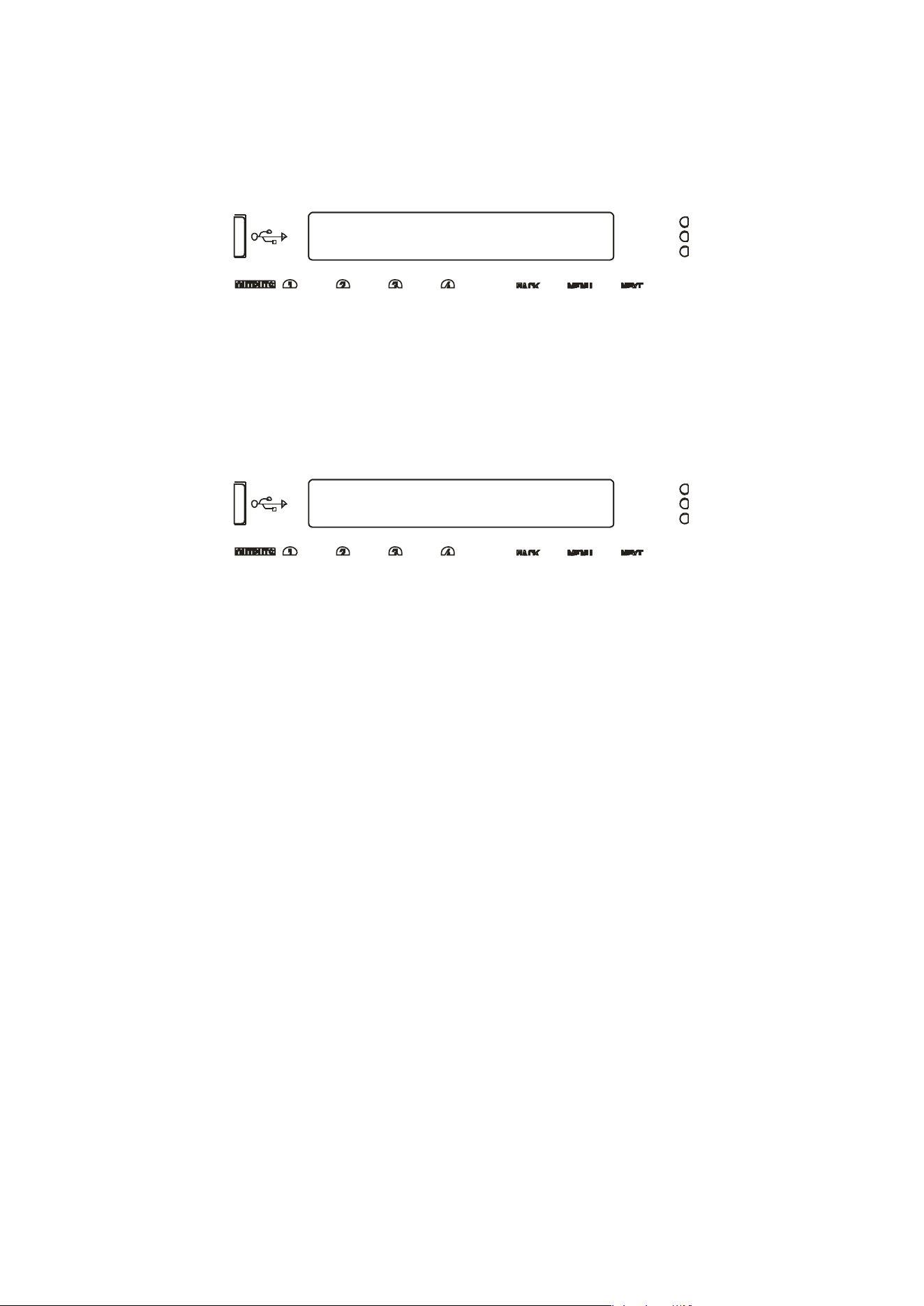
CONFIGURATION Sub-Menu
Input AES Selection
Input AES Selection
XLR C= Ana: XLR D= Ana *
=== Selection Changed ===
Press [ENTER] to CONFIRM
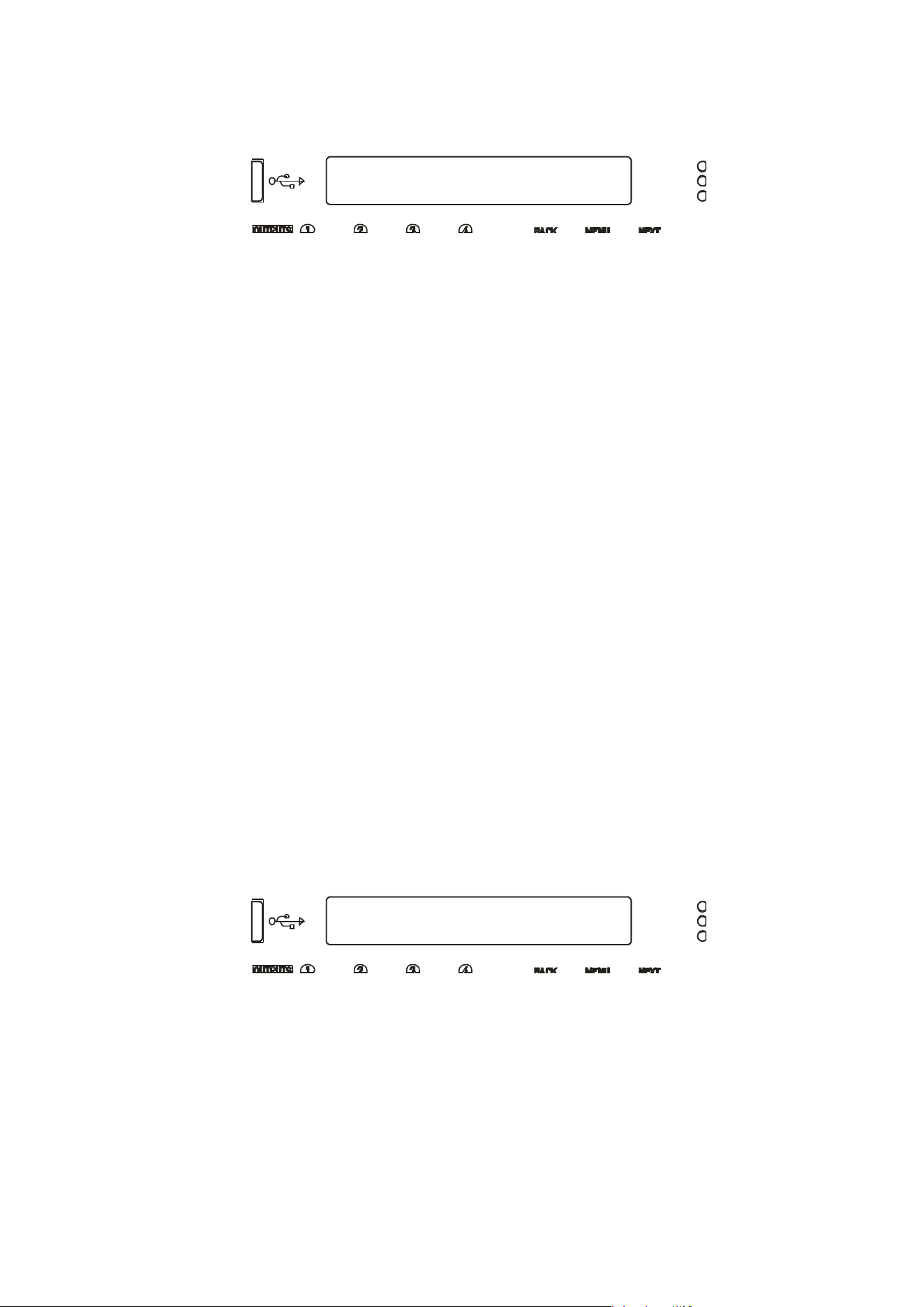
Switching from Analogue to AES Sources
To sel
ect inputs, from the home screen, press MENU, choose the CONFIGURATION Sub-Menu
and press ENTER.
Use the encoder or BACK and NEXT keys to find the Input AES Selection option and press
ENTER.
The screen will now show the current choice for the physical XLR inputs on channels C&D:
Use the encoder or BACK and NEXT keys to cycle between the four combinations, of analogue
(Ana) or Digital (AES). Press ENTER to confirm the choice, and again to confirm if changes
have been made.
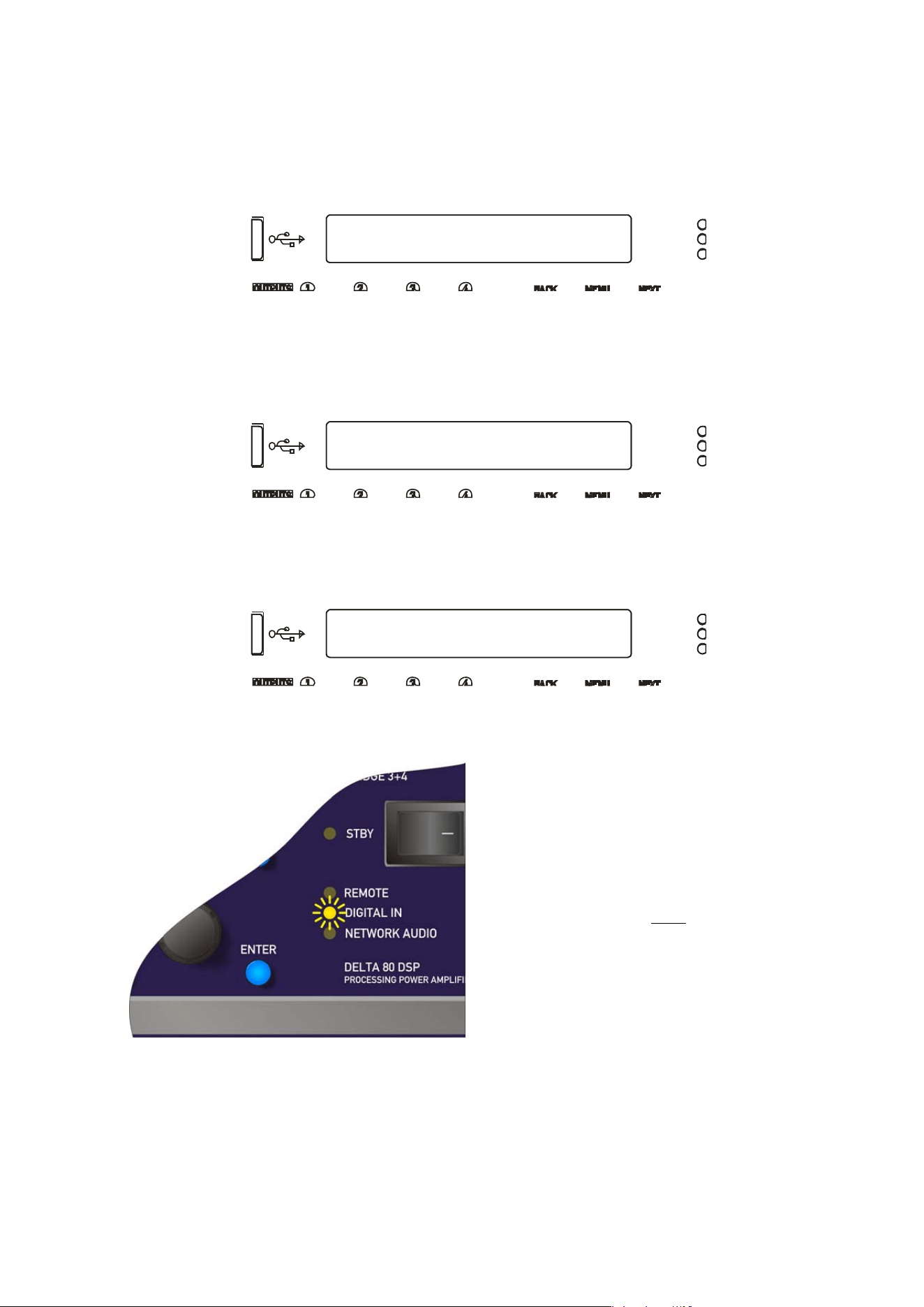
If a digital source is chosen for either XLR, the DIGITAL IN LED on the front panel will
illuminate.
Note that the DIGITAL IN LED being
illuminated does NOT mean that an AES
source is being used or routed anywhere
within the amplifier. It is an indication that
an AES connection has been selected for
the rear XLR sockets.
The DIGITAL IN LED will flash if AES has
been chosen as a primary source for an
input channel and there is a loss of lock or
connection to EITHER AES stream.
Delta Series D40/80/100 DSP Operating Instructions Page 37
CONFIGURATION Sub-Menu
Input Source Selection
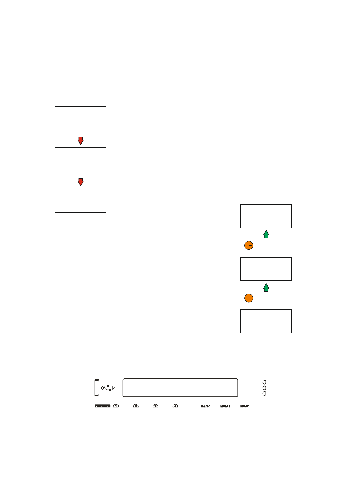
Choosing Sources for Input Processing and Failover Configuration
What is Failover?
From firmware version 1.30 onwards, your amplifier supports comprehensive source failover
to secondary or even tertiary sources should the primary source fail. Using this system
assumes you have more than one source format available (so, for example, an AES stream,
plus an analogue backup, or a Dante stream plus analogue backup.)
In fact, your amplifier is capable of setting up a three tier system, so
even in the case of a secondary source failure, it can default back to
an analogue source. Analogue is always the lowest priority failover
source.
A source failure is defined differently for AES inputs and for Dante
inputs. For AES sources it is indicated by a loss of signal (so either a
failure of the upstream device) or disconnection. For Dante sources it
is indicated by loss of signal, disconnection and additionally by a loss
of subscription.
As analogue sources cannot be verified for signal integrity, if
analogue is chosen as the primary source, the failover system will not
be offered.
The failover system can also be programmed to restore the source,
should secondary or primary sources return, with a hold time to
prevent erratic behaviour in the case of intermittent faults.
The Network and AES LEDs on the front panel also indicate if the
primary source has failed: If the Network Audio or AES LEDs are
flashing, then they are selected for primary operation but selection
has moved to secondary or final source(s).
Failover selections are stored as part of a “Routing” memory” and also are
therefore included in storage of an “Everything” memory. For more
information on how to store and recall settings, please see page 48.
Source Selection and Failover
To choose sources, from the home screen, press MENU, choose the CONFIGURATION Sub-
Menu and press ENTER.
Use the encoder or BACK and NEXT keys to find the Input Source Selection option and press
ENTER.
PRIMARY SOURCE
IS IN USE
US E S ECO NDA RY
S O UR CE CHO I CE
USE FINAL
S O UR CE CHO I CE
(I F S ELECTED )
PRIMARY SOURCE FAILURE!
S ECO NDA R Y S O UR CE FAI LU RE!
RETURN TO
PRIMARY SOURCE
US E S ECO NDA R Y
S O UR CE CHO I CE
FI NA L S O U R CE CHO I CE
IN USE
( I F S ELECTED )
PRIMARY SOURCE RESTORED
S ECO NDA R Y S O U R CE R ES TO R ED
WAIT FOR PROGRAMMED
RECOVERY TIMEOUT...
WAIT FOR PROGRAMMED
RECOVERY TIMEOUT...
Page 38 Delta Series D40/80/100 DSP Operating Instructions
Input Source Selection
Primary A = Analogue A
=== Selection Changed ===
Press [ENTER] to CONFIRM
The screen will now show the current choice for the first input processing channel (A):
Use the encoder or BACK and NEXT keys to scroll through the eight choices for this input.
These will be:
Four
analogue sources:
Analogue A
A
nalogue
B
{
Analogue
C}
A
nalogue
D
And
four digital sources, depending on the AES selection:
AES A
AE
S B
{
Dante
C}
{
Dante
D}
The choices
shown above would be shown if AES has been selected on XLR C. Analogue C is
shown in brackets to indicate that this selection will result in no audio, either because the
input is currently unavailable (due to input selection choices in the case of Analogue C) or
because the input does not exist (due to the network audio card not being fitted in the case of
the Dante C and Dante D).
Press ENTER when the required input source is shown. If the source chosen is analogue then
no failover operation can be used on that channel, and the next processing channel will be
selected and so on, running through input channels A-D.
Configuration of the inputs using analogue only is therefore the same as previous versions of
firmware.
Finally, if anything has been changed, the confirmation screen will show:
Press ENTER to confirm the changes and exit to the home screens.
Delta Series D40/80/100 DSP Operating Instructions Page 39
Input Source Selection
Failover>Secondary = Yes *
Input Source Selection
Second A = AES C *
Input Source Selection
Failover>Analogue = Yes *
Input Source Selection
Recover Time:3 Secs *
Inp: DiA, DiB, AnC, AnD
247:My Everything Memory
If a digital selection has been made for a primary source on any channel, then pressing NEXT
after this selection will ask if Failover is to be used:
Use the encoder or BACK and NEXT to select Yes if you wish this input to use the Failover
system and automatically switch to your secondary input source, should the primary fail.
Press ENTER.
The secondary source must now be chosen:
Use the encoder or BACK and NEXT keys to scroll through the eight choices for this input.
Selecting an analogue source as the secondary will finish the selection process for this input
and move onto the primary choice for the next input. If a digital source is chosen for the
secondary, then a final step will determine if the tertiary (final) failover source, which can only
be analogue is to be used:
Only the four analogue sources will be offered, and any in brackets {Analog D} will highlight
that this choice will result in no audio, for the reasons as explained on page 36. Press ENTER
to either move to the next input setup or the final step, which is the recovery time for the
failback system. This will only be shown if a channel has failover enabled.
Use the encoder or BACK and NEXT keys to select the time for the system to hold before
reselecting the higher order source. It is possible to prevent the higher order source taking
over again by selecting “Never” from the list. Press ENTER to confirm the changes and exit
to the home screens.
Selecting the IN A-D Bank on the front panel will show the current sources in use for each
processing channel and this will update if a failback source is used with the accompanying
digital source LED flashing:
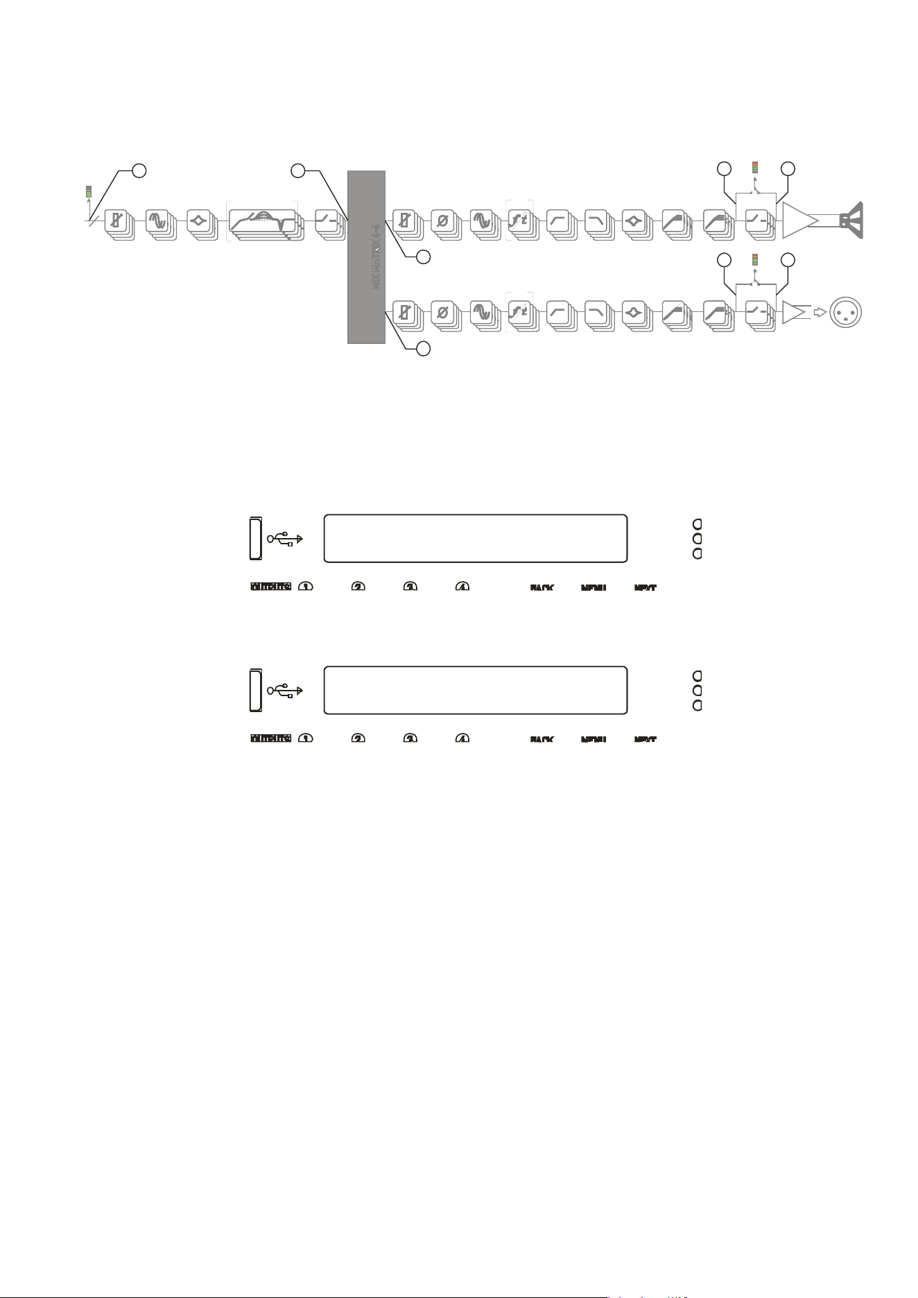
Page 40 Delta Series D40/80/100 DSP Operating Instructions
CONFIGURATION Sub-Menu
Digital Output Source
Digital Output Source
Source = Aux Outputs *
Changing Network Output Source
If your a
mplifier has a network audio card fitted (Dante) then, as well as being able to route
four channels of audio from the network, it is possible to route four channels of audio back
onto the network. The possible sources for the network outputs are always selected as a
group of four, and there are eight points within your amplifier’s DSP than can be chosen.
To choose sources, from the home screen, press MENU, choose the CONFIGURATION Sub-
Menu and press ENTER.
Use the encoder or BACK and NEXT keys to find the Digital Output Source option and press
ENTER.
Use the encoder or BACK and NEXT keys to choose between one of the following sources:
Off (Muted)
The network outputs source is disconnected and no audio is transmitted. The Dante
connection is maintained and visible on the network
Inputs
Source : audio is sourced from the input to the DSP, just after the source switching
matrix, before any processing.
Amp Outputs
Source : audio is sourced just after all amplifier output’s processing but
pre-mute
so the network copies will
not
be affected by local (or remote) mutes.
Aux Outputs
Source : audio is sourced just after all auxiliary output’s processing but
pre-mute
so the network copies will
not
be affected by local (or remote) mutes.
Matrix Inputs
Source : audio is sourced just after all input channel’s processing but before the
mix matrix — network outputs will be affected by input mutes.
PROG. - LIMITERS - PEAK MUTEPEQ x 9DELA Y DYNA M I C EQ x 3GAIN
4
PROG. - LIMITERS - PEAK MUTE
POWER
AMP
AUXILIARY
OUTPUTS [XLR]
SPEAKER
OUTPUTS
MUTE
PEQ x 9FIRDELAY HP F - XO VER - LP FGAIN
PEQ x 9FIRDELAY HP F - XO VER - LP FGAIN
POLARITY
POLARITY
INPUT PROCESSING CHANNELS A-D OUTPUT CHANNELS 1-4 (POWER AMPLIFIER CHANNELS)
AUX CHANNELS 1-4 (XLR OUTPUT CHANNELS)
83
7
2
6
5
4
1

Delta Series D40/80/100 DSP Operating Instructions Page 41
Changing Network Output Source cntd…
A
mp Matrix
Source : audio is sourced just after the auxiliary output’s routing matrix (so will
share the same audio feeds) but before all output processing.
Aux Matrix
Source : audio is sourced just after the amplifier output’s routing matrix (so will
share the same audio feeds) but before all output processing.
Amp Outputs+M
Source : audio is sourced just after all amplifier output’s processing
post-mute
so
the network copies will be affected by local (or remote) mutes.
Aux Outputs+M
Source : audio is sourced just after all auxiliary output’s processing
post-mute
so
the network copies will be affected by local (or remote) mutes.
Press ENTER to confirm the changes and exit to the home screens.
PROG. - LIMITERS - PEAK MUTEPEQ x 9DELA Y DYNA M I C EQ x 3GAIN
4
PROG. - LIMITERS - PEAK MUTE
POWER
AMP
AUXILIARY
OUTPUTS [XLR]
SPEAKER
OUTPUTS
MUTE
PEQ x 9FIRDELAY HP F - XO VER - LP FGAIN
PEQ x 9FIRDELAY HP F - XO VER - LP FGAIN
POLARITY
POLARITY
INPUT PROCESSING CHANNELS A-D OUTPUT CHANNELS 1-4 (POWER AMPLIFIER CHANNELS)
AUX CHANNELS 1-4 (XLR OUTPUT CHANNELS)
83
7
2
6
5
4
1
Page 42 Delta Series D40/80/100 DSP Operating Instructions
CONFIGURATION Sub-Menu
Output Routing
Output Routing
Routing = 2 x 2 WAY *
Changing Crossover Configuration
As the amplifier output’s configuration setup is identical to the auxiliary output’s
configuration, this section will just explain the former. The configuration of the amplifier
outputs 1-4, and auxiliary outputs 1-4 have separate entries in the Configuration sub-menu,
but operate identically. Once the input sources and AES selections have been set up, the last
part of the process is to determine what actual routing configuration is required from the
“outputs” of the four input processing channels.
This is the mix matrix. The mix matrix can function either in a “Boolean” operation mode,
where input signals still have the capability to be mixed together to feed an output channel’s
processing, but at fixed standard levels, or as a fully variable mixer.
There is also a selection of useful templates if used in the “Boolean” mode, which will
preconfigure not only the routing, but also useful starting points for each outputs’ crossover
filters.
To change configuration, from the home screen, press MENU, choose the CONFIGURATION
Sub-Menu and press ENTER.
Use the encoder or BACK and NEXT keys to find the Output Routing option and press ENTER.
Use the encoder or BACK and NEXT keys to choose from the following routing options:
Full Matrix
This mode offers continuously variable send levels from the four input processing
channels and the adjustment of the levels is then through individual output editing as
explained on page 34.
Free Assign
This mode allows the input sends to be selected as ON or OFF and intelligently
adjusts the send levels to maintain 0dB on the output — this is further explained on
the next page.
1 x 4 WAY
All four outputs are fed from input processing channel A’s output and assigned
default crossover points, which may then be adjusted if required.
2 x 2 WAY
Outputs 1 & 2 (or Aux 5 & 6) are fed from input processing channel A’s output, and
outputs 3 & 4 (or Aux 7 & 8) from channel B. Default crossover points are assigned.
4 x 1 WAY
Input processing channel A feeds output channel 1, B to 2, C to 3 and D to 4.
Crossover points are not assigned and will be set to full range — this can be changed
manually if required.
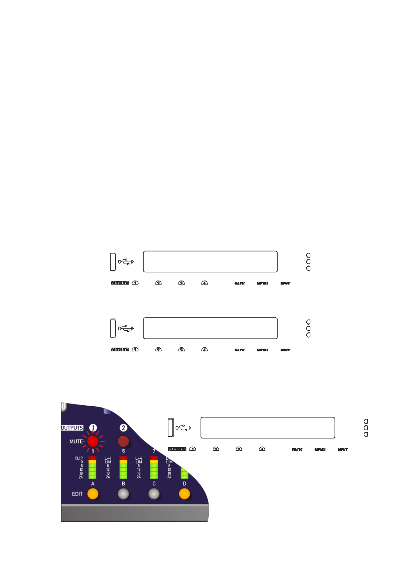
Delta Series D40/80/100 DSP Operating Instructions Page 43
CONFIGURATION Sub-Menu
Output Routing
Output Routing
Routing = Free Assign *
Output Routing
Routing Out1 = A+D *
Using Free Assign Mode
Free assign mode allows any combination of inputs to be routed to an output, with the send
levels being intelligently adjusted to ensure that the output levels sum to 0dB.
So, if two inputs are summed to a particular output, their gains will be dropped by 6dB so that
if both input levels are 0dB they will sum to produce a 0dB level at the output (assuming the
output gain as not been adjusted by the user).
If three inputs are summed, their gains will be reduced by 9.5dB so if all three inputs are 0dB,
so the output will be 0dB.
Lastly, if all four inputs are summed to an output channel, the gains will be reduced by 12dB.
If this method of operation is not desired, the same summing can be achieved without the
automatic gains adjustments by switching to Full Matrix mode and manually setting the send
levels as required.
Select Free Assign mode when changing the output routing (separately for power amp
outputs and auxiliary outputs).
To change configuration, from the home screen, press MENU, choose the CONFIGURATION
Sub-Menu and press ENTER.
Use the encoder or BACK and NEXT keys to find the Output Routing option and press ENTER.
Use the encoder or BACK and NEXT keys to choose Free Assign and press ENTER.
The first MUTE key will begin to flash and the EDIT keys will illuminate to show which input
processing channels are being routed to this output as well as being show on-screen. In the
example below, output 1 is being fed from A+D:
Use the encoder or BACK and NEXT keys
to choose the required routing
combination. The EDIT key LEDs will
change in sympathy with the input
selection.
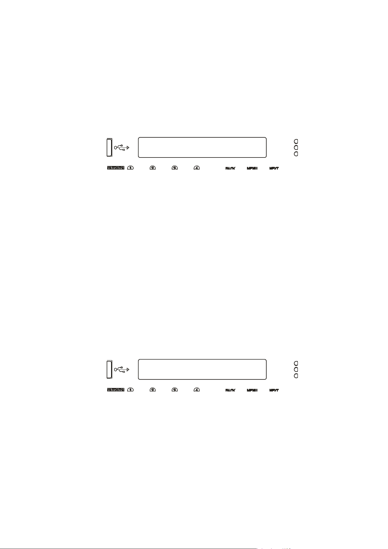
Page 44 Delta Series D40/80/100 DSP Operating Instructions
Output Routing
AutoLimiter TimeCst:Yes*
Output Routing
Bridging = None *
Press ENTER to move on to the next output channel or press the channel’s MUTE key to
select it. When all channels have been routed, press ENTER — the unit will run through any
remaining channels (if output 3 had been manually selected, for example, then ENTER would
run through channel 4 before moving on to the final set-up selections).
The next set-up selections are concerned with using automatic time constants for the limiters
and selecting bridged configurations.
The screen will first show:
MC
2
advise setting the limiter time constants automatically. They are based on the frequency
of this channel’s high pass crossover filter. Unless you have a particular reason to not use
the auto setting, set this to YES and press ENTER.
Bridged Mode for Output Pairs
Output
pairs can be selected to run in a bridged configuration to realise higher output powers.
When operating in bridged mode, the minimum impedances are doubled.
The minimum load in bridged mode is 4 ohms.
For details of
how to connect to the amplifier when running in bridged mode, please see page
16.
Selecting bridged mode is available through the CONFIGURATION > Output Routing menu and
as part of the set-up wizard. Bridged mode is not available for auxiliary output configuration
and should instead be selected on the externally driven “slave “ amplifier.
The screen will show:
Use the encoder to select which channel pairs are to be bridged:
1<>2 - bridge outputs 1 & 2 only
3<>4 - bridge outputs 3 & 4 only
1<>2 & 3<>4 — bridge both output pairs
Confirm selection with ENTER — final section of the configuration wizard will then ask about
resetting/clearing parameters as explained in the next section. If a bridged mode has been
selected there are some changes apparent in the interface to confirm this.
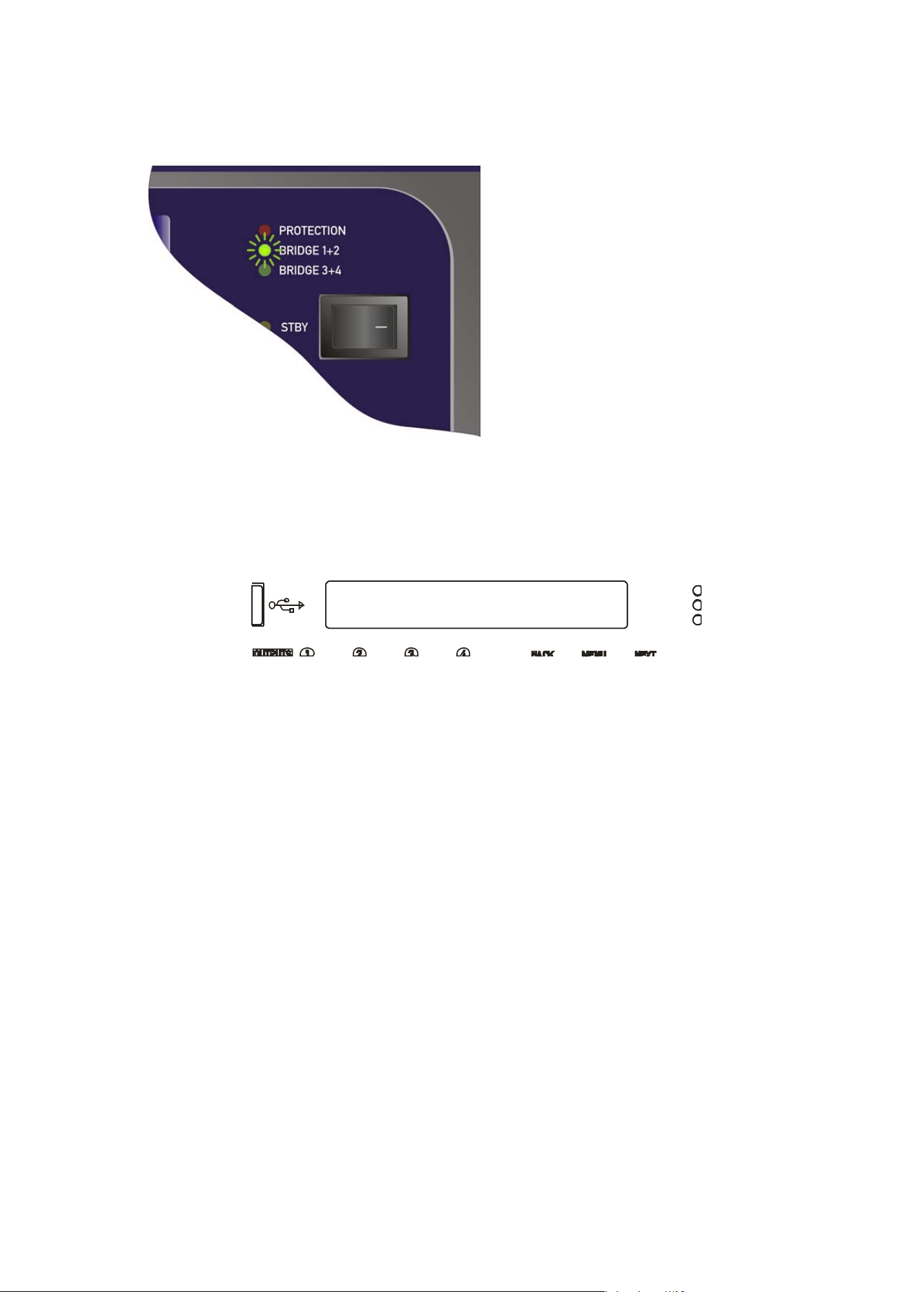
Delta Series D40/80/100 DSP Operating Instructions Page 45
1<B>2 Output 1 Gain
Output Gain = 0.0dB
Depending on what bridged mode are active the appropriate LED will illuminate above the
power switch:
There are some changes operationally
when a pair of channels are bridged.
Channel MUTE keys will be automatically
ganged;
Meters for the bridge pair will read
identically;
and lastly
Channel EDIT keys will be automatically ganged, and the display reflects the bridged mode
by changing to show the following when a bridged pair are edited:
In this example, the bridged pair are outputs 1 & 2 and this will be displayed if EDIT is pressed
on either output channel.
Bridged status is stored in an output memory, and ignored if this memory is recalled into the
auxiliary channels.
Page 46 Delta Series D40/80/100 DSP Operating Instructions
Output Routing
Clear Out Settings:Yes*
CONFIGURATION Sub-Menu
Output Ganging
Resetting Audio Parameters
R
esetting parameters is available through the CONFIGURATION > Output Routing menu and
CONFIGURATION > Auxiliary Routing menu as part of the set-up wizard.
The final set-up query is about resetting the current parameters. If you have already edited
the outputs’ DSP settings and are setting up routing last, make sure you select “No” when
asked about resetting, or all your filter, delay limiter and crossover parameters will be
cleared!
If “Yes” is selected, then, depending on format chosen, all outputs will be set to full range
(no crossover), limiters at max threshold (so minimum protection), delays and gains at
zero, polarity normal and all bands of EQ to PEQ mode, 1kHz, Q of 3.0 and 0dB. All
output/auxiliary channels will also be muted for safety!
Certain formats will preset the crossover frequencies to give a useful starting point:
Selecting a 2 x 2 way configuration will preset the output crossovers as
Outputs 1 + 3: <10Hz — 1.62kHz, 24dB/Oct. Link-Riley
Outputs 2 + 4: 1.62kHz - >32kHz, 24dB/Oct. Link-Riley
Selecting a 1 x 4way configuration will preset the output crossovers as
Output 1: <10Hz — 149Hz, 24dB/Oct. Link-Riley
Output 2: 149Hz — 1.31kHz, 24dB/Oct. Link-Riley
Output 3: 1.31kHz — 8.00kHz, 24dB/Oct. Link-Riley
Outputs 4: 8.00kHz — >32kHz, 24dB/Oct. Link-Riley
In both cases, all other DSP functions are reset as in bold above.
Hint: This procedure can be used to quickly clear all EQ — simply run through all the steps of
either output or auxiliary routing as appropriate without changing anything and select “Yes”
when asked about clearing output settings.
Ganging Channels for Editing
To make editing of multiple channels simpler (for example, stereo input sources or two-way
output editing), it’s possible to gang channels together so that any edits applied to one will
automatically be applied to the other (or others).
Ganging is separated for inputs, outputs and auxiliary channels, but the method of setting
them up is identical so only the output ganging option will be covered here.
To change output ganging, from the home screen, press MENU, choose the CONFIGURATION
Sub-Menu and press ENTER.
Delta Series D40/80/100 DSP Operating Instructions Page 47
Output Routing
Ganging = 1+3 2+4 *
Aux1&3 Extern 1 Gain
Output Gain = +12.5dB
Use the encoder or BACK and NEXT keys to find the Output Ganging option and press ENTER.
Use the encoder or BACK and NEXT keys to choose the required ganging option and press
ENTER. If the ganging mode has changed, confirm this with a final press of ENTER and the
ganging is complete.
Note that ganging assumes the settings of the lowest numbered channel in the gang is the
initial master channel and so any changes to ganging will immediately copy the settings from
the lowest member in the gang to all other ganged channels.
For example — adding channel 3 to a gang of 1+3 will instantly make channel 3’s settings
identical to channel 1.
Mutes remain unganged at all times (except in bridge mode — see page 44), as does polarity.
Ganged channels are indicated by the EDIT keys illuminating together and the display
showing the member numbers of the gang:
The label shown (“Extern 1”) is always the lowest gang member, no matter which EDIT button
has been pressed in the gang.
Labels can only be changed through remote control software or the DeltaDirect iPad app.
Ganging states are stored in output memories and will be recalled when an output memory is
recalled to either amplifier outputs or auxiliary outputs.
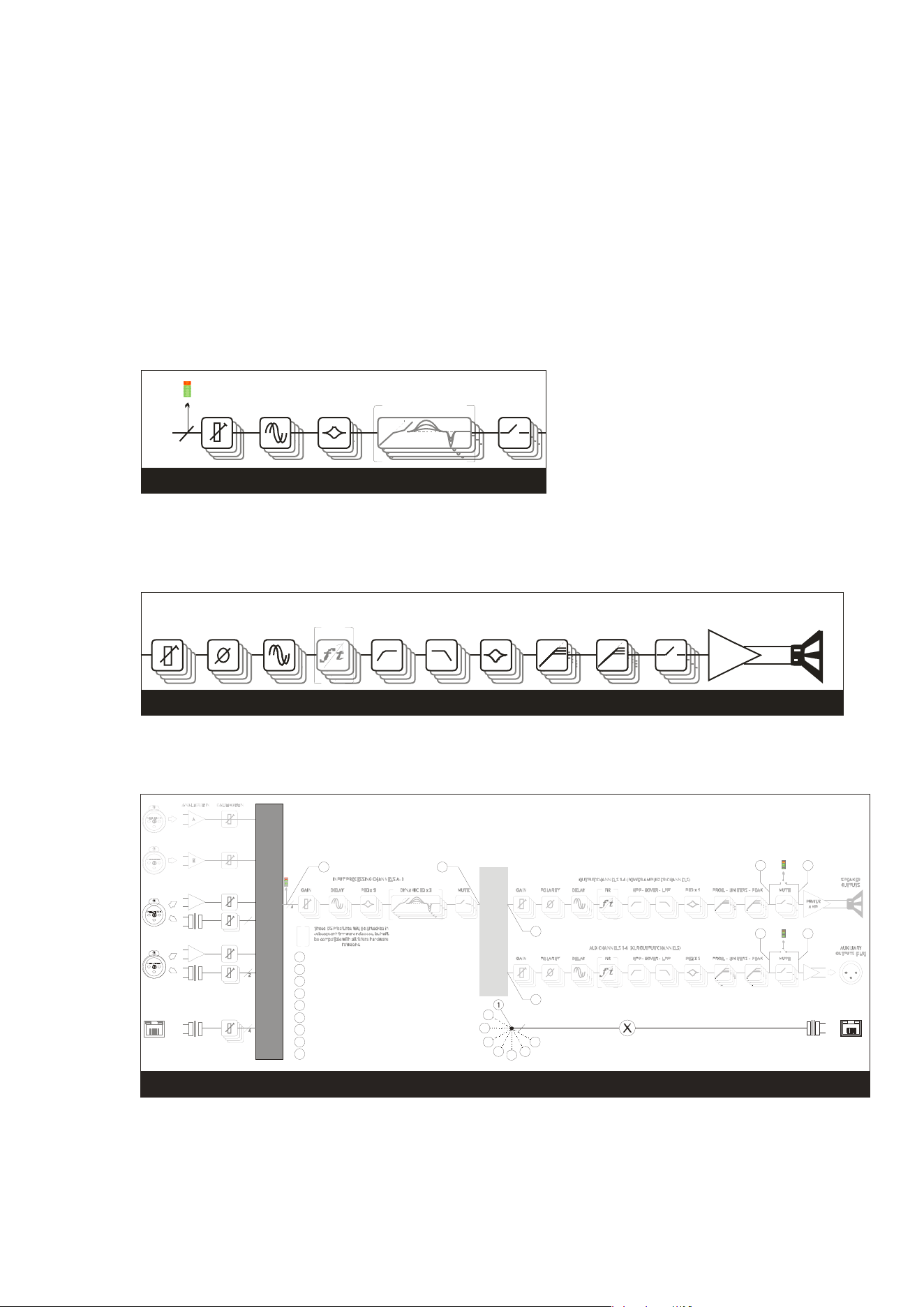
Page 48 Delta Series D40/80/100 DSP Operating Instructions
Operating Your Amplifier: Storing and Recalling Settings
Memory Ove
rview
The memory in your amplifier is organised into three different types — input memories, output
memories and source memories. Input and output memories are formatted in banks of four
channels at a time — be that four input channels or four output channels (amplifier or auxes).
Source memories are a different type and are global to the entire amplifier. It is also possible
to store and recall a complete copy of all current settings (so, input, source, amplifier and aux
outputs) in a memory location — “Everything”.
Input memories contain all the EQ, gains, delays, mutes and names for the four input
channels.
PEQ x 9DELA Y DYNAM I C EQ x 3GAIN
4
SOU RCE S WITC H 12-4
I NP U T P R OCES S I NG CHA NNELS A - D
MUTE
INPUT MEMORY
Output
memories contain all the EQ, crossover filters, FIR data (if applicable), polarities,
gains, delays, mutes, limiters (including auto time constants setting), names, bridge modes,
and routing from the mix matrix (including free assign and full matrix gains if applicable).
This is for the bank of four amplifier channels, or the bank of four auxiliary output channels.
OUTP U T CHANNELS 1- 4 ( P O WER AM P LI FI ER CHA NNELS )
PROG. - LIMITERS - PEAK
MUTE
POWER
AMP
SPEAKER
OUTPUTS
PEQ x 9FIRDELAY HP F - XO VER - LP FGAIN POLARITY
OUTPUT MEMORY
Source mem
ories contain the all data concerned with additional choices of source selection
encompassing AES/Analogue switching, Network Audio Output Source and the source
switching (choosing which inputs feed the input DSP channels) plus failover options.
NETWORK
INPUTS ABCD*
C
D
ANALOGUE C OR AES A+B
ANALOGUE D OR AES C+D
OR
OR
2
SOURCE SWITCH 12-4
*Network audio input and output option (Dante)
INDEPENDENT NETWORK OUTPUTS ABCD
NETWORK
OUTPUTS*
MIX MATRIX 4-4
2
3
4
5
4
NETWORK OUTPUTS OFF
1
CO P Y O F S ELECTED I NP U T S O UR CES
2
COPY OF POWER AMP OUTPUTS, PRE MUTE
3
COPY OF AUXILIARY OUTPUTS, PRE MUTE
4
COPY OF INPUTS A-D, POST PROCES SING
5
COPY OF POWER AMP OUTPUTS POST MATRIX, PRE PROCESSING
6
COPY OF AUXILIARY OUTPUTS POST MATRIX, PRE PROCESSING
7
COPY OF POWER AMP OUTPUTS, POST MUTE
8
COPY OF AUXILIARY OUTPUTS, POST MUTE
0
6
7
8
72
83
6
5
41
SOURCE MEMORY
Memories all
exist in a numbered list and depending on the type of memory to be recalled,
the list will be filtered to only show the applicable memory type.
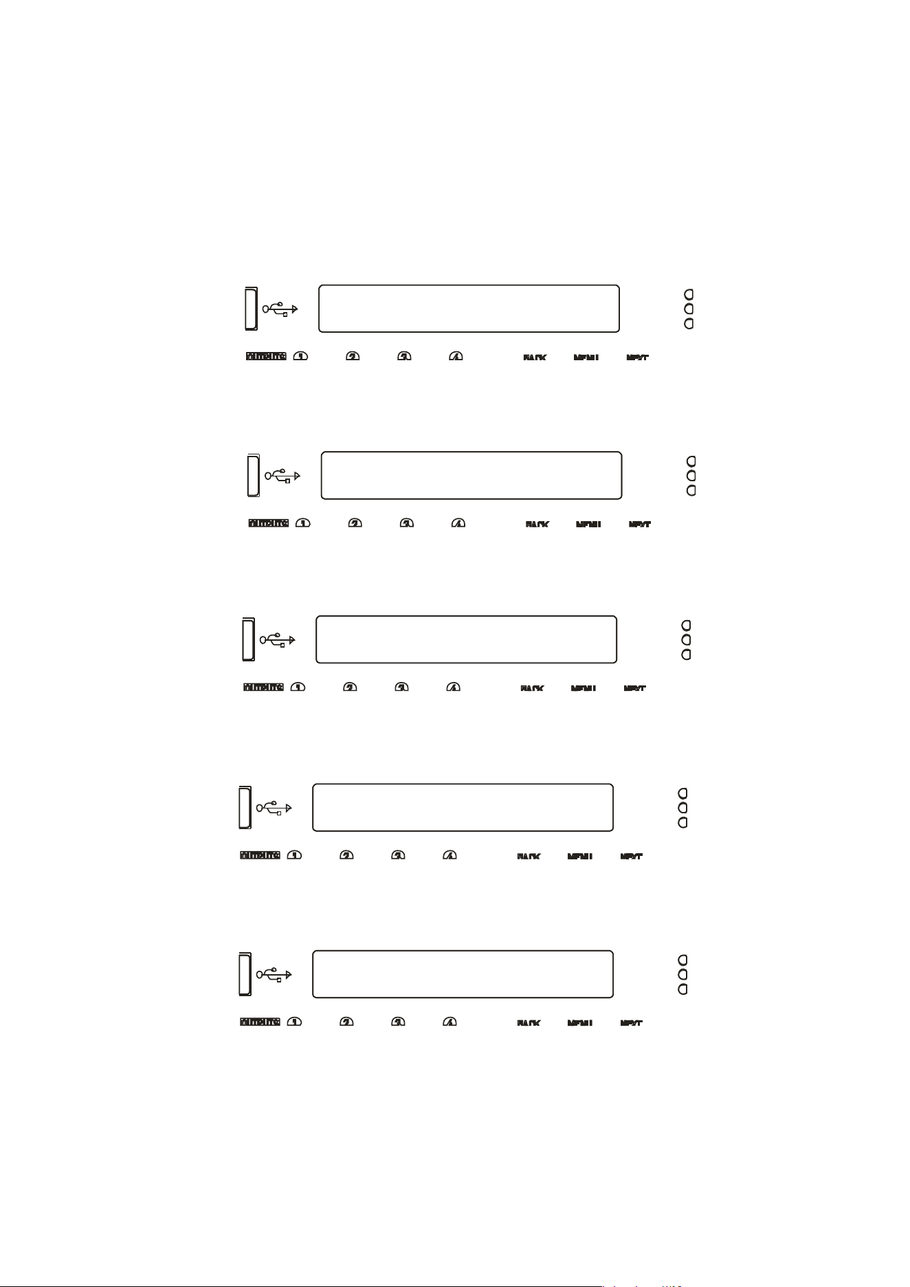
Delta Series D40/80/100 DSP Operating Instructions Page 49
MEMORY Sub-Menu
Recall an Output Memory
STORE
an
O
u
t
pu
t
M
emory
Store from Amp Outputs *
STORE an Output Memory
103:
STORE an Output Memory
94:LEFT SIDE 6 SUBS ?
Enter Memory Name
94:LEFT SIDE 6 SUBS ?
Storing a Memory…
W
hen a memory is to be stored, the type is first selected (Input, Output, Source or Everything)
and then in the case of an Output memory, this must be further qualified to determine if the
stored data is to originate from the amplifier outputs or the auxiliary outputs.
To store a memory, from the home screen, press MENU, choose the GLOBAL MEMORY
Sub-Menu and press ENTER.
Use the encoder or BACK and NEXT keys to choose either Input or Output memory type as
appropriate and press ENTER.
In the previous example, the extra step is to choose whether to store the four amplifier
outputs’ data, or the four auxiliary outputs’ data. Choose with encoder and press ENTER.
Use the encoder to choose the memory number to use — memories that are already used will
show the current name and a question mark on the bottom line and ask for confirmation if
chosen:
The name may now be edited/entered using a combination of the encoder and the BACK/NEXT
keys to move along the name. Press ENTER when complete, or QUIT to exit.
Memory is then stored, with a confirmation message and the amplifier will return to the
default screen on the selected bank.
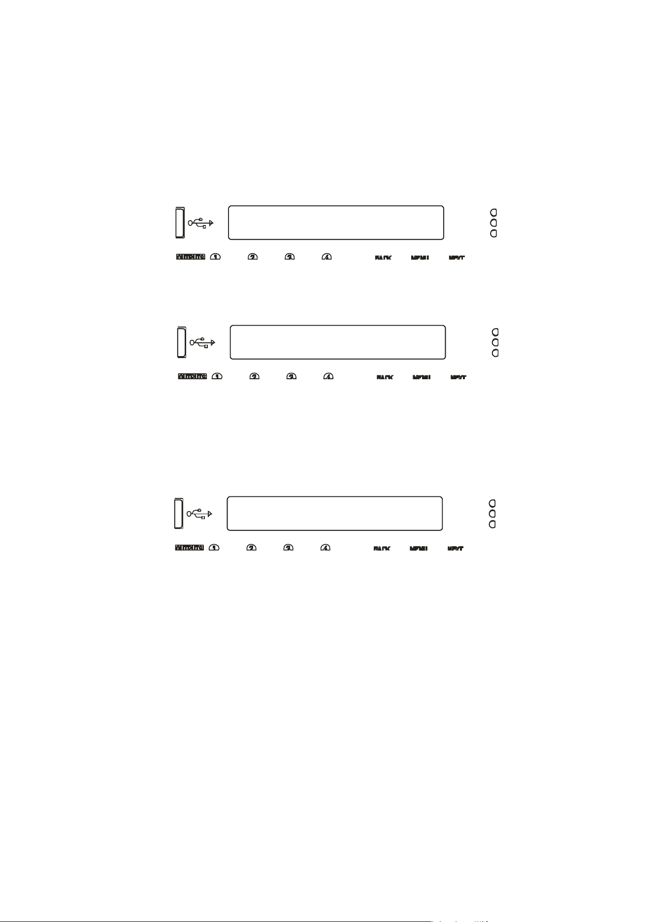
Page 50 Delta Series D40/80/100 DSP Operating Instructions
MEMORY Sub-Menu
Recall an Output Memory
RECALL an
O
u
t
pu
t
M
emory
Recall to Aux Outputs *
RECALL an Output Memory
94:LEFT SIDE 6 SUBS
Recalling a Memory…
W
hen a memory is recalled, after choosing the type (Input, Output, Source or Everything),
recall of Output memories is further qualified by what bank of outputs the recalled data is to
affect — amplifier or auxiliaries.
To recall a memory, from the home screen, press MENU, choose the GLOBAL MEMORY
Sub-Menu and press ENTER.
Use the encoder or BACK and NEXT keys to choose either Input or Output memory type as
appropriate and press ENTER.
Use the encoder to choose the memory required, remembering that the list will only contain
memories of the chosen type, and so the numbers may not be contiguous (so there may be
gaps!)
Press ENTER and confirm. If the routing configuration of the memory just recalled is
different to the current configuration, the outputs will be muted for safety.
Dependant on the bank selected, the display will by default show the name of the last input,
amp output or aux output memory recalled, or the same on all three if an “Everything”
memory was recalled.

Delta Series D40/80/100 DSP Operating Instructions Page 51
Operating Your Amplifier: System Adjustments
Overview
Under the System Sub-Menu you’ll find all the non-audio features relating to your amplifier’s
operation. As these are self-explanatory, they are summarised in the table below:
System Sub Menu Option What it’s for…
System Status Check firmware version and system information
LCD Contrast Adjust the viewing angle for the display
LED Brightness Adjust the brightness of meters and switch LEDs
Wakeup Time Add a delay before start of audio fade up or keep muted
Output Meter Option Choose if meters should show pre or post mute
Clip Hold Time Set how long a clip or limit condition is held on meters
Filter ‘Q’
/
Bandwidth Show PEQ filter bandwidth as ‘Q’ or ‘1/Q’ (bandwidth)
Delay Time/Distance Choose to show delay time in metres, feet or time (mS)

Page 52 Delta Series D40/80/100 DSP Operating Instructions
Operating Your Amplifier: Remote & External Interfaces (Incl. Dante)
Overview
Yo
ur amplifier is equipped with multiple options for remote control. It can operate as a single
device via a USB connection to the front panel, and this can also be used as a converter to an
RS485 network, where other Delta devices or XTA processing units may be connected.
It may also be controlled via an Ethernet connection and again will relay data onto an RS485
network if required.
The Ethernet and USB connections can be used in an intelligent switchover mode, where the
Ethernet connection is active, but will be overridden by a USB connection, allowing quick
connection to a system via the front panel without needing to reconfigure the current remote
interface setup.
The RS485 network can be used on its own as third means of communication, if the amplifier
is part of a bigger system and an Ethernet connection is not available.
Using an Ethernet connection, multiple amplifiers can be connected directly to a standard
Ethernet switch, or WiFi router, allowing for wireless communication. Connection to a WiFi
router is required to control amplifier(s) with the DeltaDirect app.
The GPIO port on your amplifier can be configured to feed back a variety of alarm signals
(such as over temperature threshold, or protection triggered) and offer simple closed contact
control of standby mode, mutes or memory recalls. It also accepts variable voltages which
allow direct level control of selected channels’ gains.
The optional Dante interface gives your amplifier network audio capabilities to input and
output streams, and can be configured for AES67 compatibility. It is possible to fix the IP
address of the Dante card independently to the IP address of your amplifier’s control port and
these options are covered further in this manual starting on page 65.
The selection of which Dante audio streams are “subscribed” is performed using Audinate’s
“Dante Controller” free application. For further information on its operation, please see their
own extensive documentation.
Remote Control Software Choices
Your amplifier is designed to be fully configured via AudioCore, our fast, intuitive software
platform that works alongside the DeltaDirect app for Apple iPad devices.
Main configuration is performed via AudioCore, either with a wired connection via Ethernet,
USB or RS485. Connection to amplifiers is also possible wirelessly using the Ethernet
connection if this is via a wireless router.
Tuning of a system can then be performed wirelessly (via a WiFi connection) using just the
iPad, which allows full adjustment of all aspects of a network of Delta DSP amplifiers.
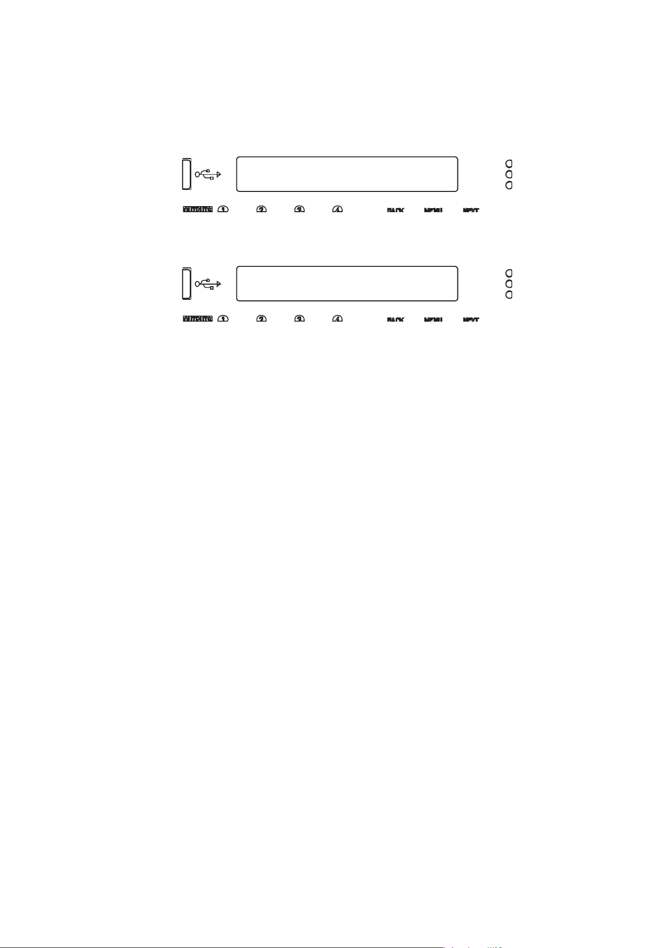
Delta Series D40/80/100 DSP Operating Instructions Page 53
INTERFACE Sub-Menu
External Interface
External Interface
Mode= Ethernet or USB
Configuration of the Remote Interface
To configure the remote interface, from the home screen, press MENU, choose the
INTERFACE Sub-Menu and press ENTER.
Use the encoder or BACK and NEXT keys to select External Interface and press ENTER.
Use the encoder or BACK and NEXT keys to choose the required interface and press ENTER.
This will invoke a series of further options depending on the interface chosen — these are
explained below:
Mode = OFF: Interface is disabled and no external comms are active. This is useful
if you need to fully secure your amplifier as well as locking the front panel (for more
information on security and locking see page 58.)
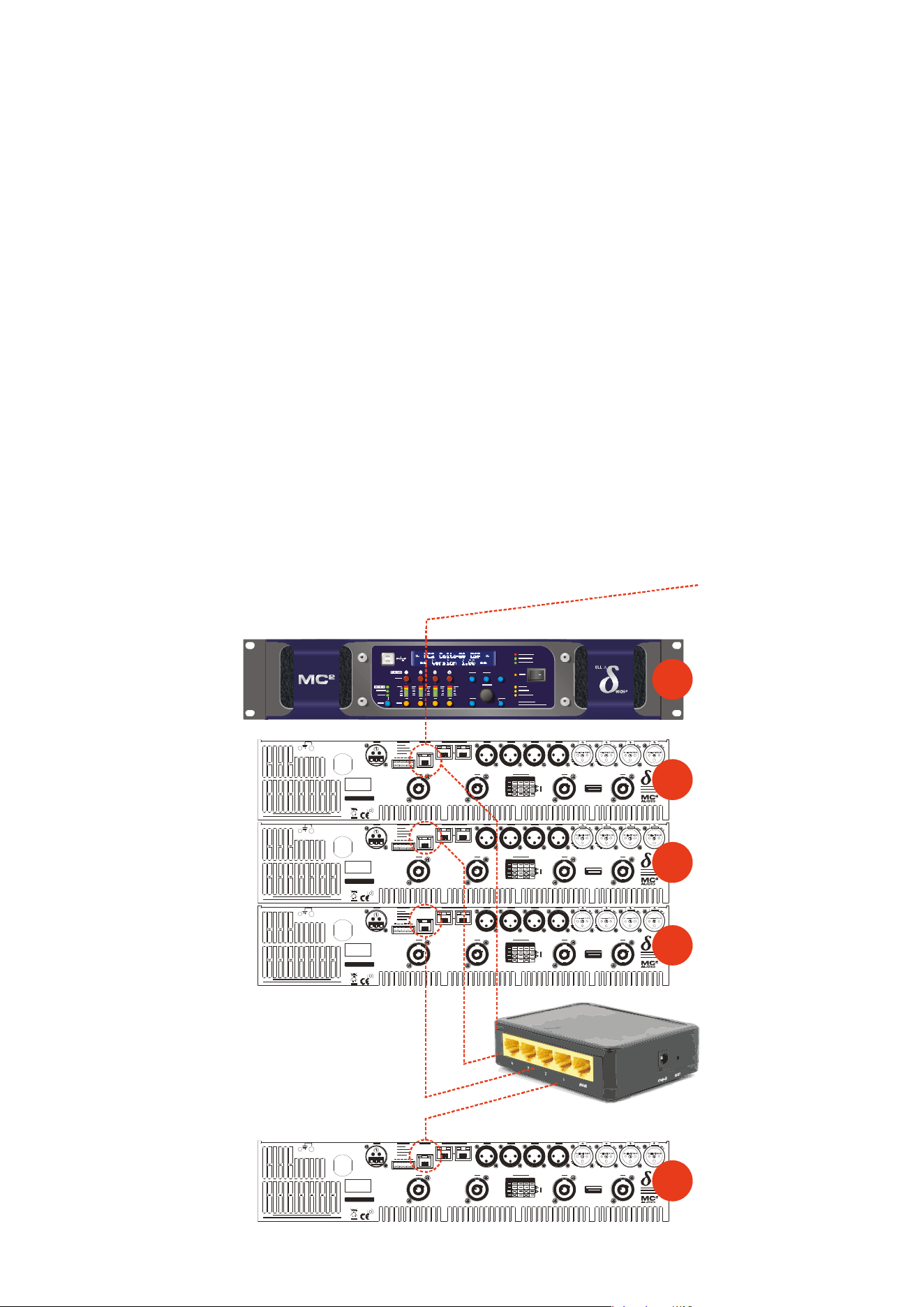
Page 54 Delta Series D40/80/100 DSP Operating Instructions
Mode =
Ethernet Only: The Ethernet control port on the rear panel is active.
Selecting this choice will then ask for the following further information to be confirmed:
RS485 Mode: Choose Relay to relay all remote control data onto the RS485
network for connection to further devices (other Delta DSP amplifiers or XTA
processors)
RS485 Speed: Only shown if RS485 Mode = Relay or Simple: set RS485 baud
rate (recommended to use 115200 unless working with older DP224 and DP226
processors in which case use 38400)
Remote ID Number: Set a device ID (still required even on Ethernet
connections). This must be unique to the connected unit — setting the same ID on
multiple units may cause comms problems for all devices.
IP Mode: Choose either Static or Auto IP. Auto IP will generate an IP address
based on unique hardware features such as MAC address. Choose Static if you need
to select the IP address to lie within a specific range, for instance when working
within a larger infrastructure.
GtWay: The gateway address is used for external access to the Internet and
should be left at the default setting.
SubNt: The subnet mask is used to subdivide IP addresses into groups that allow
further sub-groups addressing to be defined, so further extending the address range.
Leave at default 255.255.255.0 unless specifically required.
IP: The IP address specifies the amplifier’s unique identifier on the Ethernet
network. It is used in conjunction with the amplifier’s Remote ID number to identify
individual devices on the network. Make sure this is not set to the same value as any
other devices or comms problems will occur.
SERIAL NO.
CH. D CH . C CH . B CH. AOUTP UT
DCBA
SERIES
SERIAL NO.
CH. D CH . C CH . B CH. AOUTP UT
DCBA
SERIES
SERIAL NO.
CH. D CH . C CH . B CH. AOUTP UT
DCBA
SERIES
Ethernet to P
C
This unit’s interface set as:
Mode: Ethernet Only
RS485 Mode: Off
Remote ID Number: 1
IP Mode: Auto IP
Connect to all units with standar
d
CAT5 Ethernet cable to router.
Rear of First Unit
“Control” Port to Router with
CAT5 Ethernet Cable
Rear of Next Unit
“Control” Port to Router with
CAT5 Ethernet Cable
This unit’s interface set as for #1
EXCEPT
Remote ID Number: 2
SERIAL NO.
CH. D CH . C CH . B CH. AOUTP UT
DCBA
SERIES
Rear of Next Unit
“Control” Port to Router with
CAT5 Ethernet Cable
This unit’s interface set as for #1
EXCEPT
Remote ID Number: 3
Rear of Last Unit
“Control” Port to Router with
CAT5 Ethernet Cable
This unit’s interface set as for #1
EXCEPT
Remote ID Number: N
#1
#1
#2
#3
#N
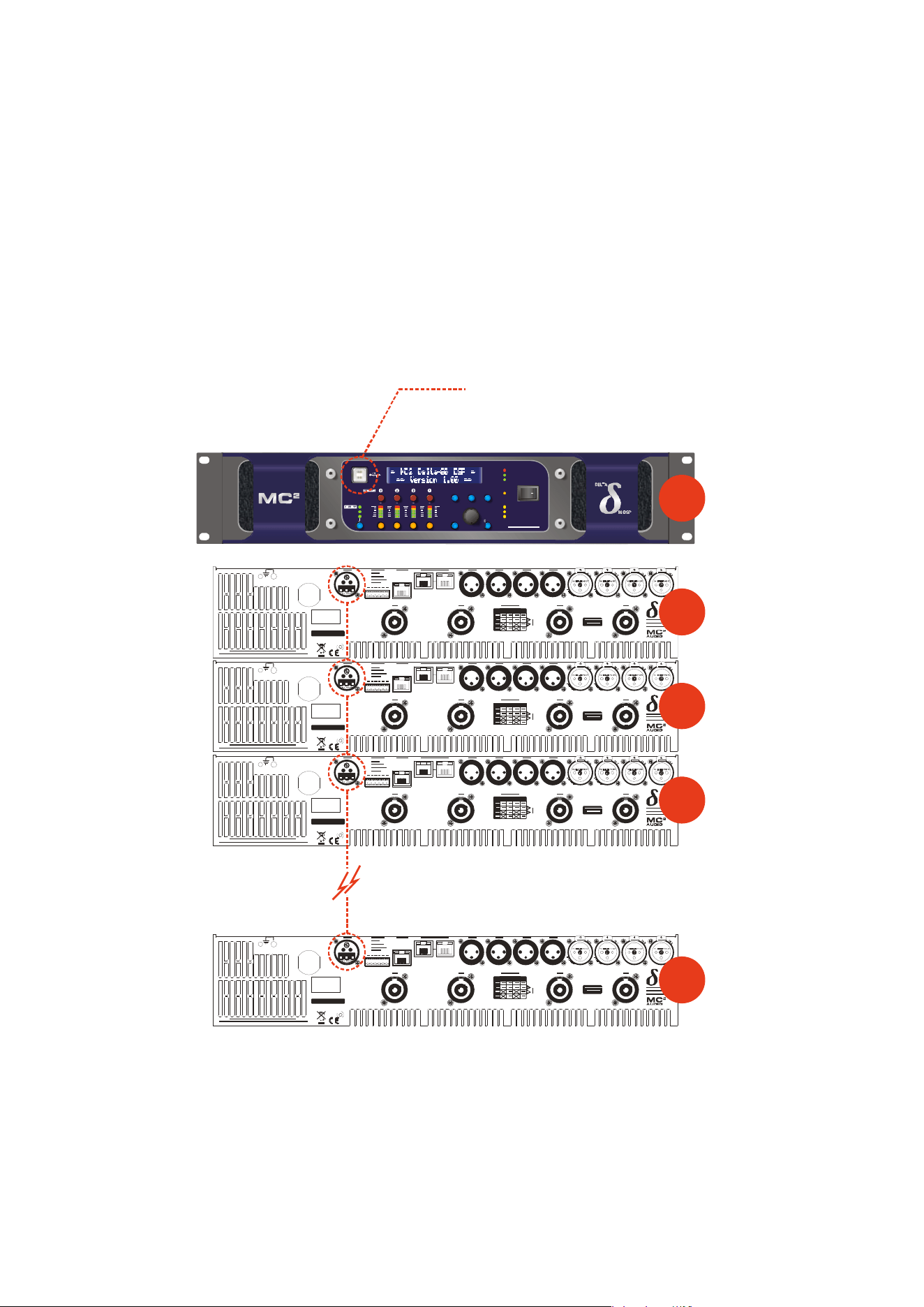
Delta Series D40/80/100 DSP Operating Instructions Page 55
Mode =
USB Only: The USB socket on the front panel is active. Selecting this choice
will then ask for the following further information to be confirmed:
RS485 Mode: Choose Relay to relay all remote control data onto the RS485
network for connection to further devices (other Delta DSP amplifiers or XTA
processors)
RS485 Speed: Only shown if RS485 Mode = Relay or Simple: set RS485 baud
rate (recommended to use 115200 unless working with older DP224 and DP226
processors in which case use 38400)
Remote ID Number: Set a device ID (still required even on Ethernet
connections). This must be unique to the connected unit — setting the same ID on
multiple units may cause comms problems for all devices.
ME NU
IN A -D
AUX 5-8
MU TE
EDIT
BACK
QUIT ENTER
PROTECTION
BRIDGE 1+2
BRIDGE 3+4
AES IN
ADJUST
AUDIO NET.
AB C D
56 78
BANK
DEL TA 80 DS P
REMOTE
STBY
SERIAL N O.
CH. D CH . C CH. B CH . AOUTPUT
DCBA
SERIES
SERIAL N O.
CH. D CH . C CH. B CH . AOUTPUT
DCBA
SERIES
SERIAL N O.
CH. D CH . C CH. B CH . AOUTPUT
DCBA
SERIES
USB to PC
This unit’s interface set as:
Mode: USB Only
USB Speed: 115200
RS485 Mode: Relay
RS485 Speed: 115200
Remote ID Number: 1
Rear of First Unit
Connect RS485 to next unit
Rear of Next Unit
Connect RS485 to next unit...
This unit’s interface is set as
Mode: RS485 Only
RS485 Speed: 115200
Remote ID Number: 2
SERIAL N O.
CH. D CH . C CH. B CH . AOUTPUT
DCBA
SERIES
Rear of Next Unit
Connect RS485 to next unit...
This unit’s interface is set as
Mode: RS485 Only
RS485 Speed: 115200
Remote ID Number: 3
Rear of Last Unit
Connect RS485 to next unit...
This unit’s interface is set as
Mode: RS485 Only
RS485 Speed: 115200
Remote ID Number: N
#1
#1
#2
#3
#N

Page 56 Delta Series D40/80/100 DSP Operating Instructions
Mode =
Ethernet Or USB: The Ethernet control port on the rear panel is active, so
long as the amplifier is not connected via USB, whereupon it automatically takes priority.
Selecting this choice will then ask for the following further information to be confirmed:
RS485 Mode: Choose Relay to relay all remote control data onto the RS485
network for connection to further devices (other Delta DSP amplifiers or XTA
processors)
RS485 Speed: Only shown if RS485 Mode = Relay or Simple: set RS485 baud
rate (recommended to use 115200 unless working with older DP224 and DP226
processors in which case use 38400)
Remote ID Number: Set a device ID (still required even on Ethernet
connections). This must be unique to the connected unit — setting the same ID on
multiple units may cause comms problems for all devices.
IP Mode: Choose either Static or Auto IP. Auto IP will generate an IP address
based on unique hardware features such as MAC address. Choose Static if you need
to select the IP address to lie within a specific range, for instance when working
within a larger infrastructure.
GtWay: The gateway address is used for external access to the Internet and
should be left at the default setting.
SubNt: The subnet mask is used to subdivide IP addresses into groups that allow
further sub-groups addressing to be defined, so further extending the address range.
Leave at default 255.255.255.0 unless specifically required.
IP: The IP address specifies the amplifier’s unique identifier on the Ethernet
network. It is used in conjunction with the amplifier’s Remote ID number to identify
individual devices on the network. Make sure this is not set to the same value as any
other devices or comms problems will occur.
Remember that this mode is purely an automatic priority switching version of an Ethernet
or USB connection — it is not possible to interconnect amplifiers via the Ethernet cables
either directly or via a router — use the RS485 bus for device interconnection.
All three connection methods will relay data either explicitly (RS485 using the hardware
bus connection) or electronically (USB or Ethernet through the processor) if required.
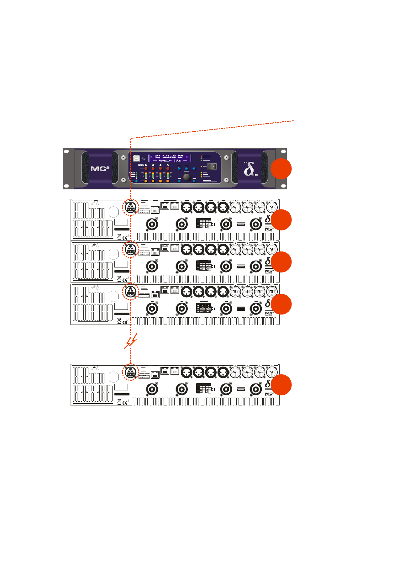
Delta Series D40/80/100 DSP Operating Instructions Page 57
Mode =
RS485 Only: The RS485 port on the rear panel is active. Selecting this choice
will then ask for the following further information to be confirmed:
RS485 Speed: Set RS485 baud rate (recommended to use 115200 unless working
with older DP224 and DP226 processors in which case use 38400)
Remote ID Number: Set a device ID (still required even on Ethernet
connections). This must be unique to the connected unit — setting the same ID on
multiple units may cause comms problems for all devices.
SERIAL N O.
CH . D CH. C CH . B CH . AOUTPUT
DCBA
SERIES
SERIAL N O.
CH . D CH. C CH . B CH . AOUTPUT
DCBA
SERIES
SERIAL N O.
CH . D CH. C CH . B CH . AOUTPUT
DCBA
SERIES
RS485 to P
C
Connect RS485 to first unit
via RS485-USB adapter.
This unit’s interface set as:
Mode: RS485 Only
RS485 Speed: 115200
Remote ID Number: 1
Rear of First Unit
Connect RS485 to next unit
Rear of Next Unit
Connect RS485 to next unit...
This unit’s interface is set as
Mode: RS485 Only
RS485 Speed: 115200
Remote ID Number: 2
SERIAL N O.
CH . D CH. C CH . B CH . AOUTPUT
DCBA
SERIES
Rear of Next Unit
Connect RS485 to next unit...
This unit’s interface is set as
Mode: RS485 Only
RS485 Speed: 115200
Remote ID Number: 3
Rear of Last Unit
Connect RS485 to next unit...
This unit’s interface is set as
Mode: RS485 Only
RS485 Speed: 115200
Remote ID Number: N
#1
#1
#2
#3
#N

Page 58 Delta Series D40/80/100 DSP Operating Instructions
Wireless Connection with DeltaDirect iPad App
Free y
ourself of cables and go wireless! Plug the Ethernet connection from your amplifier(s)
into a wireless router and you are good to go!
Main remote configuration of a single amplifier, or a network of amplifiers is performed
through AudioCore, with system tuning using either AudioCore again or DeltaDirect — our
elegant, intuitive app, which can be downloaded from the Apple appstore free of charge.
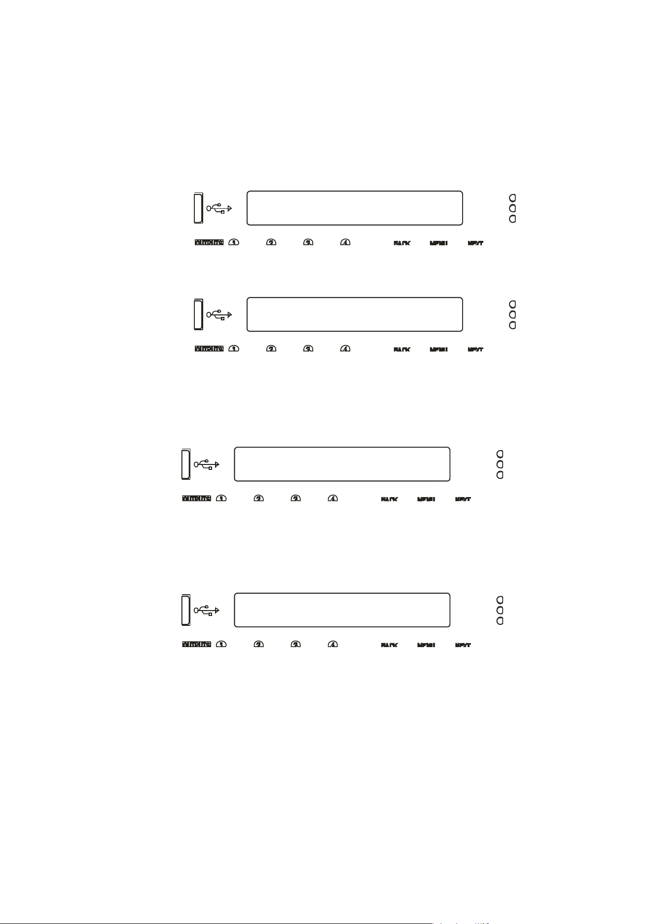
Delta Series D40/80/100 DSP Operating Instructions Page 59
INTERFACE Sub-Menu
External Interface
INTERFACE Sub-Menu...
GPI Interface
GPI1 Mode GPI2
VCA:A+B Sys.Mute*
GPI1 RS485 Relay
GPI2
Yes No*
GPIO Operation
The General
Purpose Input and Output pins on your amplifier can be programmed in a variety
of ways to adjust the operation of the amplifier.
To configure the GPI interface, from the home screen, press MENU, choose the INTERFACE
Sub-Menu and press ENTER.
Use the encoder or BACK and NEXT keys to select GPI Interface and press ENTER.
This will invoke a series of further choices to determine the operation of the inputs, as
outlined below:
Operatin
g Mode
Use the enco
der to select from the list of combinations of operating modes for the two GPI
inputs. The available combinations are given at the end of this appendix. Press ENTER to
confirm selection and move to the next option.
RS485 Relay
Use the enco
der to select if RS485 relay should be used for the two GPI inputs. Use the
encoder to choose from the four possible options and press ENTER to confirm selection finish
set-up.
To enable reception of these relayed commands, other amplifiers need to have their External
Interface set to receive on either “RS485 only” or on Ethernet/USB connections, the RS485
Relay mode must be set to “Simple” mode. Baud rate must match on all amplifiers.
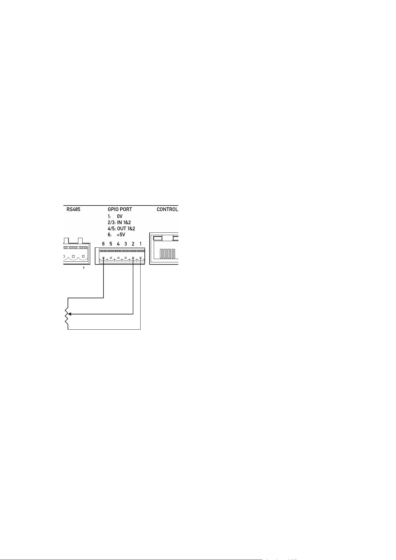
Page 60 Delta Series D40/80/100 DSP Operating Instructions
The following input control modes are available
on the GPI pins in a variety of preset
combinations.
VCA Mode
Input gains can be adjusted in channel pairs with absolute level control over the range of
+6dB to -18dB in 0.5dB steps, via an analogue voltage applied to the GPI input.
The channel
choices are
A+B, C+D or A+B+C+D. Recalling a memory or adjusting gain either remotely by
another method or via the front panel will override the VCA setting until the control is
next
adjusted (l
ast take
s priority).
The input
gain setting adjusted by the GPI input can also be transmitted as a global message
to all other connected DPA (and Delta) DSP amplifiers via RS485. See page 59 for details of
how to enable or disable this feature.
A typical connection to a GP input port for VCA control would be to connect a linear
potentiometer as shown below:
VR1 — the potentiometer should be a linear taper,
with have a value of 10k or greater to avoid cabling
losses affecting the value.
As the inputs are active over a 3V3 range and the
output on port pin 6 is +5V, the top 33% of the
potentiometer’s range will not be active.
Both GPI inputs can be used in VCA mode to
control inputs A+B on input 1, and C+D on input 2.
VCA CONTROL
GP INPUT PPORT
V
R
1
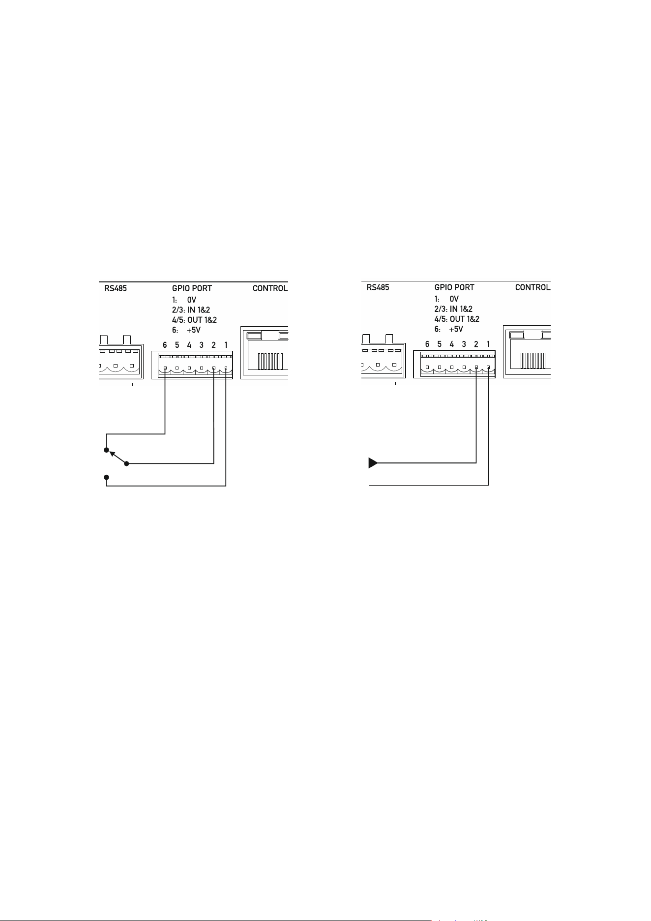
Delta Series D40/80/100 DSP Operating Instructions Page 61
Standby Mode
The amplifier can be put into or brought out of standby by applying a logic level to the selected
GPI pin.
The standby setting adjusted by the GPI input can also be transmitted as a global message to
all other connected DPA (and Delta) DSP amplifiers via RS485. See page 59 for details of how
to enable or disable this feature.
Changing standby by another method (remote message or front panel) will override the GPI
setting until the state of the GPI input is next changed (last takes priority).
A typical connection to a GP input port for standby control would be to connect a simple
changeover switch as shown below:
It is also possible to supply an external voltage trigger for the GP Input, as long as the ground
f
or the trigger source is also connected. The logic level is 3v3, but the input is tolerant of up
to 15v. Do not apply higher voltages to this input or damage to the amplifier may occur!
Hint: To bring an amplifier out of standby via the front panel, power up with ENTER + QUIT
held in.
Mutes Mode
T
he amplifier can be muted by applying a logic level to the selected GPI pin. This can either
be a “System Mute” (as with AudioCore/DeltaDirect) so when enabled all outputs (power
amps and auxes) are muted and previous mute state is restored when disabled, or “Alarm
Mute” which mutes inputs A+B+C leaving only input D active for emergency evacuation
announcements. Disabling Alarm Mute will unmute inputs A+B+C, NOT restore their pre-
alarm state.
The mutes setting adjusted by the GPI input can also be transmitted as a global message to
all other connected DPA (and Delta) DSP amplifiers via RS485. See page 59 for details of how
to enable or disable this feature.
Changing mutes by another method (remote message or front panel) will override the GPI
setting until the state of the GPI input is next changed (last takes priority).
A typical connection to a GP input port for mutes control is the same as above, for standby
control.
LOGIC CONTROL
GP INPUT PORT
EXTERNAL LOGIC CONTROL
GP INPUT PORT
3V3 INPUT, 15V TOLERANT
VOLTAGE IN
GROUND
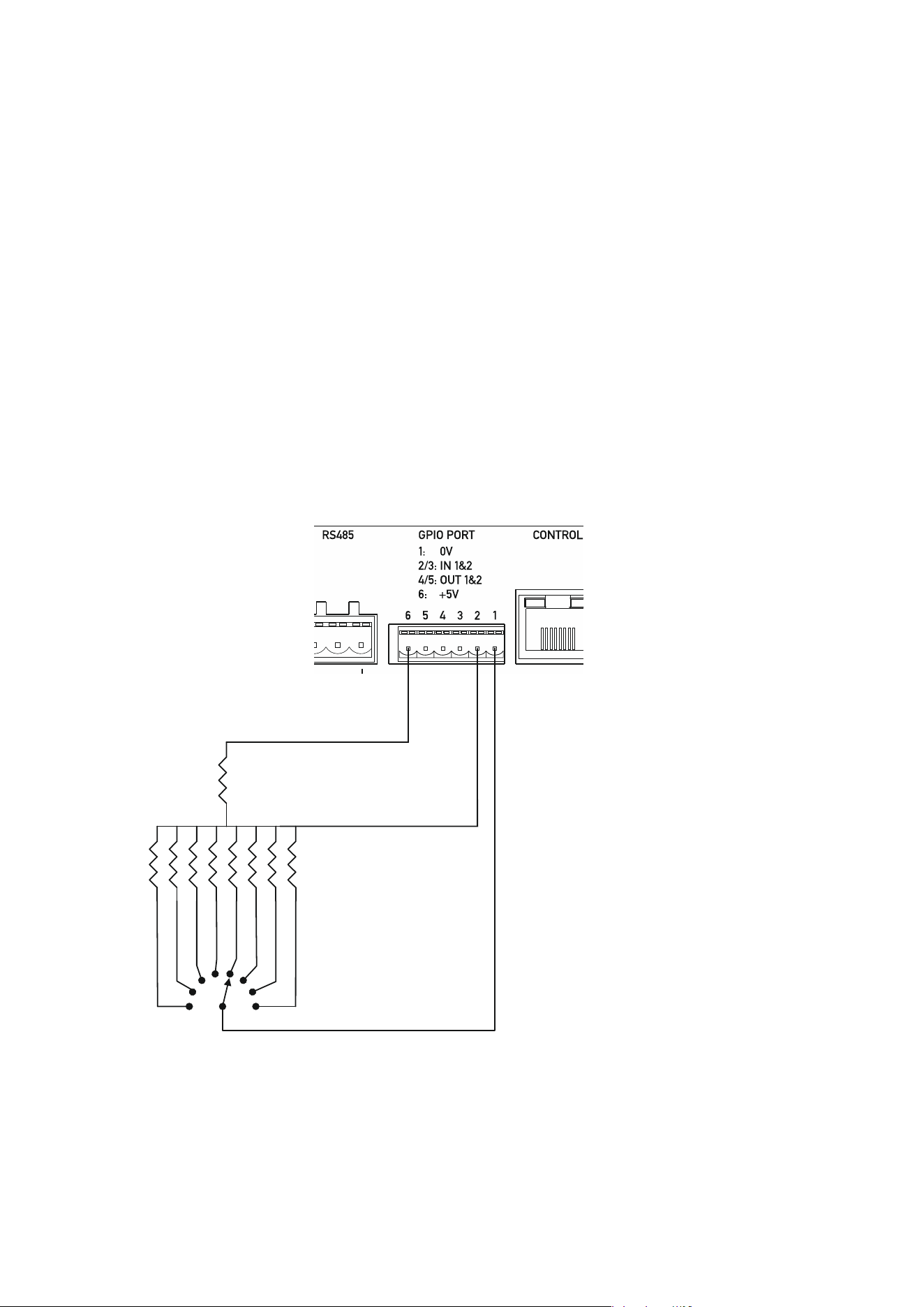
Page 62 Delta Series D40/80/100 DSP Operating Instructions
Memory Recall Mode
The amp
lifier can recall memory settings based on either a logic level (memory 1 or 2) or a
voltage level (memories 1 to 8 are available).
Select the required recall mode and press ENTER — either “Mem 1-8” or “Mem 1/2”.
The memory recall selected by the GPI input can also be transmitted as a global message to
all other connected DPA (and Delta) DSP amplifiers via RS485. See page 59 for details of how
to enable or disable this feature.
Recalling a memory by another method (remote message or front panel) will override the GPI
setting until the state of the GPI input is next changed (last takes priority).
When toggling between two memories in mode “Mem 1/2”, the simple switch logic method
can be used as for controlling mutes or standby modes as described on the previous page.
For the “Mem 1-8” mode, it is recommended that a multi-position switch is used, as the input
relies on a voltage threshold to act as the trigger for a memory recall.
Such an arrangement is shown below:
Typical resistor values to
allow recall of the first
eight memories would be
as follows:
R1 = 1K
R2 = 0R (short circuit)
R3 = 47R
R4 = 150R
R5 = 250R
R6 = 410R
R7 = 540R
R8 = 850R
R9 = 1k20R
MEMORY RECALL
CONTROL
GP INPUT PORT
(MEMS 1-8)
R
2
R3
R4
R5
R6
R7
R8
R9
R1
SW1
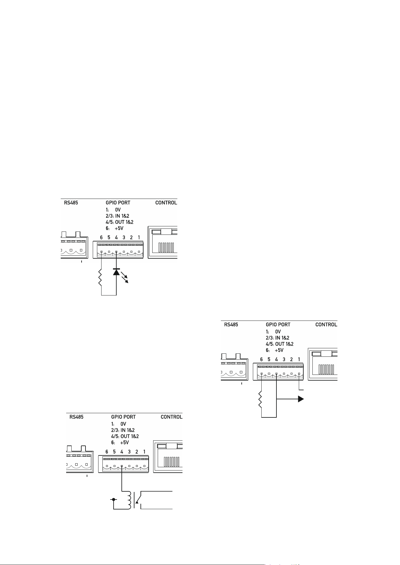
Delta Series D40/80/100 DSP Operating Instructions Page 63
General Purpose Output Pins
The general purpose output pins have a preset configuration and there are no user adjustable
options for them.
GP output 1 (port pin 4) reflects the amplifier’s standby state and is active high, so a high logic
level seen on this pin means the amplifier is in standby. An LED connected as below will be
illuminated when the amplifier is NOT in standby.
GP output 2 (port pin 5) reflects the amplifier’s “health” and is also active high. This pin will
be pulled low if the amplifier goes into protect. This also means if the amplifier loses power
or this line is disconnected accidentally, it can passively signal a problem. An LED connected
as below will be illuminated when the amplifier is NOT in protect.
Both the outputs are configured as “current sink” topology, so they can be used in a variety of
ways to provide direct LED indication, voltage level indication for external systems’
integration, or isolated output for higher voltage direct control via use of a relay.
Connecting an LED via a 330R resistor shows direct
indication of the output.
Connecting an 10K resistor across the 5V and
required output provides a voltage driven indication
of output state.
Connecting a relay coil to an output is
also possible — the coil voltage be up to
48V, and this will then provide fully
isolated control allowing switching of
other higher power loads.
R1
DIRECT LED
INDICATIO
N
GP OUTPUT
PORT
COIL ENERGISING
VOLTAGE
0v => Vrelay <= +48V
RELAY
OUTPUT
CONTACTS
ISOLATED RELA
Y
CONNECTION
SIGNALLING
GP OUTPUT
PORT
R1
5V OUTPUT
SIGNAL
GP OUTPUT
PORT
GROUND

Page 64 Delta Series D40/80/100 DSP Operating Instructions
Operating Mode Combinations
The following combinations of operation are available for the GPI port pins:
GPI1 Mode GPI2 Mode
VCA:A+B Sys. Mute
GPI1 Mode GPI2 Mode
VCA:C+D Sys. Mute
GPI1 Mode GPI2 Mode
VCA:A+B+C+D Sys. Mute
GPI1 Mode GPI2 Mode
VCA:A+B VCA:C+D
GPI1 Mode GPI2 Mode
VCA:A+B Alm. Mute
GPI1 Mode GPI2 Mode
VCA:C+D Alm. Mute
GPI1 Mode GPI2 Mode
VCA:A+B+C+D Alm. Mute
GPI1 Mode GPI2 Mode
VCA:A+B Standby
GPI1 Mode GPI2 Mode
VCA:C+D Standby
GPI1 Mode GPI2 Mode
VCA:A+B+C+D Standby
GPI1 Mode GPI2 Mode
VCA:A+B Mem 1/2
GPI1 Mode GPI2 Mode
VCA:C+D Mem 1/2
GPI1 Mode GPI2 Mode
VCA:A+B+C+D Mem 1/2
GPI1 Mode GPI2 Mode
VCA:A+B Mem 1-8
GPI1 Mode GPI2 Mode
VCA:C+D Mem 1-8
GPI1 Mode GPI2 Mode
VCA:A+B+C+D Mem 1-8
GPI1 Mode GPI2 Mode
Sys. Mute Standby
GPI1 Mode GPI2 Mode
Alm. Mute Standby
GPI1 Mode GPI2 Mode
Mem 1/2 Standby
GPI1 Mode GPI2 Mode
Mem 1-8 Sys. Myte
GPI1 Mode GPI2 Mode
Mem 1-8 Alm. Mute
GPI1 Mode GPI2 Mode
Mem 1/2 Sys. Myte
GPI1 Mode GPI2 Mode
Mem 1/2 Alm. Mute
Delta Series D40/80/100 DSP Operating Instructions Page 65
INTERFACE Sub-Menu
External Interface
Upgrade Dante Firmware
Reason = No Data
Dante Interface
AES 67 Mode = Disabled *
Dante Interface
Network Mode = DHCP *
Dante Interface Configuration
Your Dante in
terface will work straight out of the box, but should you wish to adjust settings,
from the home screen, press MENU, choose the INTERFACE Sub-Menu and press ENTER.
Use the encoder or BACK and NEXT keys to find the Dante Interface option and press ENTER.
If the screen shows a message…
…then an update is needed. Please see our website TechNotes for further instructions on
how to update the card’s firmware. If you can access AES67 compatibility options and IP
address options, then the Dante card is already compatible.
Assuming your card’s firmware is compatible, a short wizard will run, giving the option to
select AES67 compatibility
3
and select either a static or DHCP sourced IP address.
Changing this will require a reboot of the card which will happen automatically at the end of
the wizard. Press ENTER to choose Network Mode:
Unless you have a valid reason for changing this to “Static” and entering a fixed IP address,
SubNet Mask and Gateway IP address, this should be left on DHCP. Changing this will also
require a reboot of the card at the end of the wizard.
3
Audinate explain that “The purpose of the AES67 standard is to tie several existing protocols together to create an
interoperability specification. The goal of AES67 is that every audio device can eventually connect together with a
standard IT network, and share audio. Neither AES67 nor AVB are competitive equivalents to Dante. AES67 and AVB
are both a collection of standards, which are not actual implementations. Dante is a commercially supported
solution, and more than just a standard. It is important to emphasize that AES67 will be incorporated as an option
within Dante, rather than an alternative to it.“
Page 66 Delta Series D40/80/100 DSP Operating Instructions
SECURITY Sub-Menu
Unit Locking
Unit Locking
LOCK=> User Specific *
Operating Your Amplifier: Using & Clearing Security; Defaulting Settings
If you need to quickly clear all current settings and memories, there are a variety of setup
control codes that can do this for you.
Locking the
Front Panel
Your amplifier supports a comprehensive security system, that can control access to editing
of audio parameters and changing of system settings. It is password protected and can be set
locally or remotely via AudioCore.
To configure the locking system, from the home screen, press MENU, choose the SECURITY
Sub-Menu and press ENTER.
Assuming the unit isn’t already locked, press ENTER once more to choose the lock type.
User Specific
Upon pressing ENTER to select this type of lock, each parameter group is presented in turn.
Choose the type of lock (as above) using the FREQ encoder, and press ENTER to confirm each
parameter. After the last parameter, the unit requests a password. The description of this
operation is given at the end of this section.
This option allows the user to specify, for each type of parameter, whether it is to be
completely accessible (‘No Lock’), viewable but not adjustable (‘Control’), or effectively
unavailable (‘Display’). The ability to operate mutes, store or recall memories, or even access
the menus may also be locked.
Xover Only
All input parameters are available, but only the gain trim (+ 6dB) is available on the outputs,
effectively locking all the crossover settings. All mutes remain active.
Xover + Trim
All input parameters available, but no output parameters — the crossover sections are
completely locked. All mutes remain active.
Xover + Trim + Mute
As for ‘Xover + Trim’ but additionally, output mutes are locked. Input mutes remain active.
Changes Only
All parameters may be viewed, but none may be adjusted. This applies to both inputs and
outputs. All mutes remain active.
Changes + Views
No parameters are accessible — in effect the EDIT keys do nothing. All mutes remain active.
Changes + Mutes
All parameters may be viewed, but none may be adjusted. This applies to both inputs and
outputs. All mutes are also locked.
EVERYTHING
No parameters are accessible — in effect the EDIT and MUTE keys do nothing.
Delta Series D40/80/100 DSP Operating Instructions Page 67
Enter Setup Code:
[ ]
Entering the Password to Complete the Locking Operation
After selection of the lock type from the list above, a six-digit security code will be requested.
Using the MUTE keys to represent characters 1-4 and the EDIT keys to represent characters
A-D, type in a code. After the final character is entered, retype the code to confirm and lock
the unit.
Hint - To prevent external
computer control being used to adjust locked settings, be sure to
set the external interface to OFF before locking out the unit.
Unlocking
To unlock your amplifier, navigate to the SECURITY sub-menu and press ENTER, then type in
the code in the same manner as for the locking procedure above. Assuming the code is
correct, the amplifier will clear the locking in place - the code will be remembered for future
use.
If you have forgotten the code, see page 68 for the security clear procedure.
Default Settings
Your amplifier will start-up as a “four analogue inputs to four output system”, with no EQ or
limiting (apart from self-protective limiters) in place. The aux outputs will “mirror” the
analogue inputs (and so initially act just like “link” outputs, again with no EQ or limiting in
place).
Clearing Standby
To bring an amplifier out of standby via the front panel, power up with ENTER + BACK held in.
Entering Start-up Control Codes
T
urn the amplifier on with the BACK and ENTER keys held. The display will show:
Use the EDIT and MUTE keys to represent the characters A, B, C D for EDITs and 1, 2, 3, 4 for
MUTEs.
Type in one of the following codes to initiate a setup function:
D4B13D — clear all user memories and reset to defaults, keeping security and factory
alignment settings
A2341B — clear current settings to default (leaves memories, alignments and security)
AA2121 — clear security via the XTA supplied crack code (see page 68 for more information)
Page 68 Delta Series D40/80/100 DSP Operating Instructions
Enter Setup Code:
[ ]
Enter XTA Sup
pli
e
d
C
o
d
e:
Break No.=64223 [ ]
Clearing Security — Forgotten Unlock Code
Note that if you see the message “Parameters Locked!” during editing, or parameters can be
viewed but not adjusted, then this is due to preset data locking or hiding and is specific to the
currently running preset — this is not device security, and we cannot override it — it is specified
by the speaker manufacturer.
If you
have forgotten the passcode and your amplifier is locked, you will need to contact us to
unlock it after performing the following procedure. There is no master unlock code for all
amplifiers — the code is generated based on an algorithm using amplifier internal settings for
greater security.
Turn the amplifier on with the BACK and ENTER keys held. The display will show:
Use the EDIT and MUTE keys to represent the characters A, B, C D for EDITs and 1, 2, 3, 4 for
MUTEs.
Type in AA2121.
The display will now show:
Make a note of the “Break Number” shown (64223 in this example) and contact us with this —
we can then supply the code to unlock your amplifier.
Do not enter any menus or make any further adjustments to the amplifier or this code may
“roll over” and you will need to go through this procedure again. Either switch the amplifier
off or press QUIT to exit without entering a code.
Resetting security leaves does not delete any settings — it just clears the locking passcode.

Delta Series D40/80/100 DSP Operating Instructions Page 69
Looking After Your Amplifier: Maintenance
These mainte
nance instructions are for use by qualified personnel only. Before any routine
maintenance, please ensure that your amplifier is disconnected from the mains supply!
The filter behind the air intake apertures on the front of your amplifier should be cleaned or
replaced periodically, e.g. 3 -6 months. (Filters in amplifiers located in more 'dirty'
atmospheres may require more frequent maintenance).
The filter should be 'dry' cleaned, using a vacuum cleaner preferably. Running the unit
without a filter is not recommended. We recommend replacement of filters every 2-3 years,
depending on usage. Replacement filter material is available directly from us.
If the fan vents on the rear of the amplifier develop a build-up of dust/debris on the finger
guards, they can be cleaned with a dry paintbrush and a vacuum cleaner.
The casework of the amplifier may be cleaned with a lightly dampened cloth — do not use any
solvents as they will damage the paint finish and could remove printing.
If you have any doubts about carrying out maintenance, please refer to a service engineer or
contact your local dealer.
Looking After Your Amplifier: Warranty
Your amplifier is guaranteed for a period of five (5) years from the date of manufacture.
Please note that this does not apply to OEM versions of the amplifier — please consult your
manufacturer for their warranty terms. We hope that it gives you many more years of reliable
service than this, but should anything go wrong, please contact us to advise you about repairs
or any spares you might require.
Please do not attempt to repair the amplifier yourself as doing so will invalidate the warranty.
Our contact details are:
MC
2
Audio,
Units 6-8 Kingsgate
Heathpark Industrial Estate
Honiton, Devon
England
EX14 1YG
Tel: +44(0)1404 44633
Fax: +44(0)1404 44660
email: [email protected] for general enquiries
O
ur website is a great place to get started if you have any questions regarding the general use
of your amplifier or need copies of this manual in digital form, or datasheets and
photographs. The datasheets also contain architect’s and engineer’s specifications.
www.mc2-audio.co.uk
Page 70 Delta Series D40/80/100 DSP Operating Instructions
Performance Of Your Amplifier: Specifications
Main Specifications
Parameter (Units) Delta 40
DSP
Delta 80
DSP
Delta 100
DSP
Output Power per channel [Crest Factor = 4.8] (Watts)
8 Ohms 500 1000 1400
4 Ohms 1000 2000 2700
2.7 Ohms 1400 2200 3700
2 Ohms 1200 2000 3500
Output Power per channel bridged [Crest Factor = 4.8]
(Watts)
8 Ohms 2000 4000 5600
4 Ohms 2400 4000 7000
THD+N, 4 Ohms (%)
@1kHz, 1dB below max output power < 0.08 0.18 0.08
@20Hz - 20kHz, 1dB below max output power < 0.1 0.2 0.1
Gain Options (dB) 26/32 32 32
Sensitivity Options for max power (dBu) 6.23 8.3 10.7
Sensitivity Options for max power (Volts) 1.59 2.0 2.66
Frequency Response, +0/0.5dB (Hz) 20 — 20000 20 — 20000 20 — 20000
Power Consumption, Nominal @ 240V, 4 Ohms (A) 2.9 5.0 7.5
Power Consumption, Nominal @ 120V, 4 Ohms (A) 6 10.4 15.5
Dimensions H x W x D (mm)
Amplifier 88 x 482 x 428 88 x 482 x 428 88 x 482 x 428
Boxed 230 x 580 x 560 230 x 580 x 560 230 x 580 x 560
Boxed Shipping — all except UK 250 x 610 x 600 250 x 610 x 600 250 x 610 x 600
Weight (kgs)
Amplifier 10.0 10.3 10.9
Boxed — shipping 11.5 11.8 12.4
Additional S
pecifications
Parameter (Units) Delta 40
DSP
Delta 80
DSP
Delta 100
DSP
Input Impedance — Active Balanced (Ohms) 20k 20k 20k
Input CMRR (dB) > 60 > 60 > 60
Damping Factor, 1kHz, 8 ohms > 400 > 400 > 400
Signal Limiters Present Yes Yes Yes
Protection Present — Short Circuit / DC Output /
Temperature
Yes Yes Yes
Mains In-rush Control Present Yes Yes Yes
Output Power per channel, 8 Ohms (Watts)
Continuous music [Crest Factor of 2.8 or 9dB] 485 975 1360
Continuous music [Crest Factor of 4.8 or 14dB] 500 1000 1400
Continuous music [Crest Factor of 7.8 or 18dB] 515 1025 1440
Output Power per channel, 4 Ohms (Watts)
Continuous music [Crest Factor of 2.8 or 9dB] 970 1950 2620
Continuous music [Crest Factor of 4.8 or 14dB] 1000 2000 2700
Continuous music [Crest Factor of 7.8 or 18dB] 1030 2050 2780
Output Power per channel, 2.7 Ohms (Watts)
Continuous music with Crest Factor of 2.8 [9dB] 1365 1960 3600
Continuous music with Crest Factor of 4.8 [14dB] 1400 2010 3700
Continuous music with Crest Factor of 7.8 [18dB] 1435 2060 3880
Du
e to continuing product improvement, the above specifications are subject to change.
Delta Series D40/80/100 DSP Operating Instructions Page 71
Power Consumption and Thermal Emissions — Delta 40DSP
Mains
(V)
Load
(R)
Current Draw
(A)
Thermal Emissions
(W)
No Sig’l Light Average Heavy No Sig’l Light Average Heavy
240 8
1.0 1.4 2.1 3.7 240 251 269 312
240 4
1.0 1.7 2.9 5.8 240 258 290 366
240 2.7
1.0 1.9 3.4 7.1 240 264 304 402
120 8
2.2 3.0 4.4 7.7 267 277 295 338
120 4
2.2 3.6 6.0 11.7 267 285 317 392
120 2.7
2.2 4.0 7.1 14.5 267 290 331 428
Power Consumption and Thermal Emissions — Delta 80DSP
Mains
(V)
Load
(R)
Current Draw
(A)
Thermal Emissions
(W)
No Sig’l Light Average Heavy No Sig’l Light Average Heavy
240 8
1.5 2.2 3.4 6.3 360 378 410 486
240 4
1.5 2.8 5.0 10.3 360 394 453 593
240 2
1.5 3.1 5.8 12.4 360 402 474 647
120 8
3.3 4.7 7.1 12.9 400 418 450 526
120 4
3.3 5.9 10.4 21.0 400 434 493 633
120 2
3.3 6.5 12.0 25.1 400 442 514 687
Power Consumption and Thermal Emissions — Delta 100DSP
Mains
(V)
Load
(R)
Current Draw
(A)
Thermal Emissions
(W)
No Sig’l Light Average Heavy No Sig’l Light Average Heavy
240 8
2.1 3.2 5.1 9.6 504 533 582 701
240 4
2.1 4.1 7.5 15.7 504 557 647 863
240 2
2.1 4.6 8.9 19.1 504 570 682 953
120 8
4.7 6.9 10.6 19.6 560 589 638 757
120 4
4.7 8.7 15.5 31.9 560 613 703 919
120 2
4.7 9.7 18.2 38.7 560 626 738 1009
No
Sig’l = Quiescent, Light = Crest Factor of 7.8(18dB),
Average = Crest Factor of 4.8(14dB), Heavy = Crest Factor of 2.8(9dB)
For details of measurement methods please refer to the Technical Support area of our website.

Page 72 Delta Series D40/80/100 DSP Operating Instructions
Auxiliary Outputs and DSP Performance
Parameter (Units) Delta 40
/
80/100 DSP
Source Impedance — Active Balanced (Ohms) < 60
Minimum Load (Ohms)
600
Maximum Output Level (dBu) +18
ADC, DAC and DSP sample rate (kHz)
96
AES accepted sample rates (kHz) 32-192
Dynamic Range (20Hz-20kHz Unwtd, dB) >114
Distortion (@1kHz, +10dBm, %) <0.001
Signal Processing
Delay up to 650mS (inputs), 650ms(outputs) - independant
Filters Parametrics — 8 Per input / 9 per output
Each parametric can be switched to Bandpass, Allpass, Notch, VariQ,
Shelf and Elliptical response
Phase filtering — 2 degree steps on each input and output
FIR Filtering — available on all outputs — total maximum taps available: 5600 @ 48k, 2900 @ 96k*
Crossover Filters (per output)
Bessel / Butterworth 6/12/18/24/48dB per octave and Linkwitz-Riley 12/24/48dB per octave
Dynamic EQ**
3 bands (per input)
Parametric behaviour — 19.7Hz — 32kHz
‘Q’ 0.4 — 128,
Max gain automatic gain adjustment 18dB
Max ratio (cut above mode) 4:1
Max ratio (all other modes) 2:1
Attack 70uS — 2.0 Seconds
Release 11mS — 3.4 Seconds
Mix matrix mode (auxes and amplifier outputs)
Input sends to each output continuously variable from -40.0dB to _15.0dB in 0.1dB steps plus mute
Limiter
Threshold +18dBu to -12dBu (auxiliary outputs); +42dBu to +20dBu (amplifier outputs)
Attack time 0.1 to 91 milliseconds
Release time 2, 4, 8, 16 or 32 times the attack time
Clip/D-max Limiter
Look-ahead attack time,Fast, Medium or Slow release times
*taps per channel dynamically assignable — total taps of channels using FIR filtering may be less than 5600 (or 2900)
** DEQ enabled in later firmware release

Delta Series D40/80/100 DSP Operating Instructions Page 73
Appendix I: Limiters and How to Set Them Correctly
Yo
ur amplifier has two levels of dynamic protection on its outputs — a traditional program
limiter, and a peak limiter.
Program Limiter
High performance digital l
imiters are provided for each output with control over attack time,
release time and threshold parameters. This level of control allows the user to balance the
required subjective quality of the limiter against the driver protection requirements. It does
also mean that an incorrectly set limiter may sound awful!
In particular (as with all limiters) using too fast an attack or release time for the type of signal
in the pass-band will result in excessive low frequency distortion. There is provision, within
the remote software application, to set automatic limiter time constants. Use this option if
you are unsure how to set the time constants manually. We recommend the use of the
automatic setting.
In this mode the time constants will be automatically set from the corresponding channel’s
High-Pass filter frequency according to the table below.
High Pass Filter Auto Attack Time Release Time
<10Hz — 31Hz 45mS x16 (720mS)
31Hz — 63Hz 16mS x16 (256mS)
63Hz — 125Hz 8mS x16 (128mS)
125Hz — 250Hz 4mS x16 (64mS)
250Hz — 500Hz 2mS x16 (32mS)
500Hz - 1kHz 1mS x16 (16mS)
1kHz — 2kHz 0.5mS x16 (8mS)
2kHz — >32kHz 0.3mS x16 (4mS)
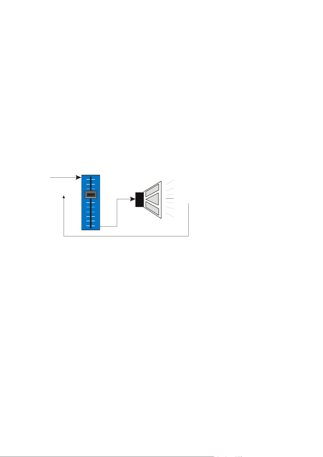
Page 74 Delta Series D40/80/100 DSP Operating Instructions
Peak Limiter
The main limitation with traditional dynamics control is the inability of the processing to react
truly instantaneously to the signal. One of the most significant advantages of digital signal
processing over analogue is the ability to delay the audio signal precisely and without
extensive complex hardware. The entire domain of digital signal processing is based around
the combination of delaying, multiplying, and accumulating numbers (representing samples
of audio) to implement all the filters and dynamics processing we have come to expect today.
In the case of dynamics processing, being able to delay a signal allows the processor module
to delay the main signal in relation to the sidechain (the signal being monitored relative to the
threshold), so that it can compensate for peaks prior to the arrival of the main signal.
Consider the situation of a monitor engineer listening to a band perform. Having no access to
dynamics processors, he has had to resort to manually ‘riding the faders’ in an attempt to
keep control of the levels. Should the level of one of the channels on his desk reach an
unacceptably high level, he will turn it down appropriately.
There is a hidden sidechain in
operation even in this case.
The main signal path is fed
through the monitor desk and
the gain controlled by
adjusting the fader. The
sidechain is formed by the
feedback path between the
engineer’s ears checking the
level and his brain instructing
his hand to turn the fader
down if the volume goes over
the threshold he has chosen.
In this case, the delay between the signal actually going over the threshold, the engineer
registering the situation, and then turning the signal down will be in the order of several
hundred milliseconds at best. This will only be true if he is not distracted — in reality, it may
be several seconds before any gain reduction is imposed on the signal to bring it under
control.
Audio Input
(Signal being
monitored)
Gain Control
Element
Output to
Amp/Speaker
System
Feedback Path from Monitor Engineer’s Ears to Hand
forming Sidechain Control Signal
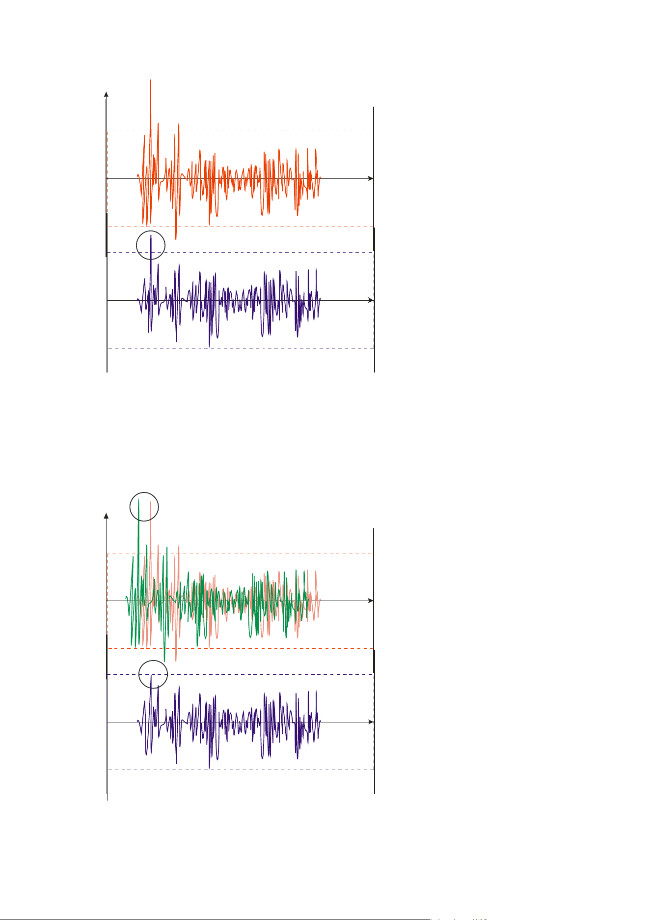
Delta Series D40/80/100 DSP Operating Instructions Page 75
For an
analogue dynamics
processor, the situation is much
better. Controlling the gain
electronically, and not relying on
a human sidechain feedback
mechanism, it can react much
more quickly.
The red waveform represents the
input to the dynamics module,
with the dotted line showing the
threshold for gain control to
occur. There are several peaks
towards the start of this signal
that are above the threshold, and
so the dynamics processing
should react to these as
appropriate. (In this case reduce
the gain).
The blue waveform shows the
output of the dynamics module.
The circled peak demonstrates that the processor has missed the first peak above the
threshold (as it is very fast and short), but has ‘caught up’ shortly afterwards, keeping all
other peaks under control. As it is unable to predict what is coming, this will always be a
failing with analogue dynamics processing.
The peak limiter pre-delays the sidechain signal, resulting in a “zero overshoot” limiter,
which is able to catch all peaks and provide a reliable absolute maximum setting for the
output of any channel.
The pre-delayed sidechain is
shown in green, with the main
signal in red. As the main signal
arrives slightly after the
sidechain, the output from the
unit does not suffer from the
overshoot problem.
Remember that this delay is only
in the order of tens of
microseconds,and is a pre-delay
— the sidechain is moved back in
time in relation to the main
signal. Inserting a delay into the
main signal path of an analogue
dynamics processor will achieve
similar results, but with the
penalty of delaying the main
signal by the amount of look
ahead delay introduced.
Level
Time
Time
Threshold for Onset of Gain Control
Overshoot here as dynamics processor cannot
predict or react fast enough to this peak.
Input of module
Output of module
Level
Time
Time
Threshold for Onset of Gain Control
No overshoot as sidechain was able to react
before the main signal arrived, due to predelay
Input of module
Output of module
Predelayed sidechain signal
Main signal arrives slightly later

Page 76 Delta Series D40/80/100 DSP Operating Instructions
The peak limiter follows the RMS limiter, has only two parameters to adjust — the release
time and the threshol
d. Note that the threshold is set to be a minimum of 2dB above the
threshold of the program limiter — setting the threshold to “10dB above” means that no more
than 10dB of overshoot above the threshold of the program limiter will ever be allowed.
The release time can also be automatically set if the RMS limiter has automatic time
constants enabled and so are set by the high pass filter frequency for that channel.

Delta Series D40/80/100 DSP Operating Instructions Page 77
Setting Accurate Limiter Thresholds — Program Limiter
Introduction
The limiters
built into your amplifier are intended to be used for loudspeaker driver
protection, as opposed to amplifier protection. The amplifier has additional limiters which
can adapt automatically to both temperature and incoming mains conditions to stay
operational and playing music for as long as possible. The following section describes how to
set up the units’ limiters to provide exceptional protection against driver overheating and
cone over-excursion. Most speaker systems are given a power rating in Watts RMS. This is
the maximum continuous power that the system will handle and often appears very
conservative. In reality, as music program is far from continuous in nature, the peak power of
the system is much higher — up to ten times the continuous figure. Any limiter, which is to
protect the driver from damage, must be able to fulfil the following tasks:
- Have an attack time which is calculated to allow transients through but keep the RM
S
le
vel below the speaker manuf
acturers specification;
- Have
a release time which is sufficiently long to avoid the limiter itself modulating the
program;
- Be
intelligent enough to adjust the envelope of the li
miter according to the frequency
content of the program mat
erial
.
The R
MS limiters are capable of performing all these tasks. The only parameter that the user
must set manually is the threshold, and it is crucial that this is done correctly.

Page 78 Delta Series D40/80/100 DSP Operating Instructions
Amplifier Outputs’ Program Limiter Lookup Table
Note that
the setting of the auxiliary outputs’ limiters needs to be referenced to the
external amplifier’s gain for correct operation. A separate lookup table and explanation is
given overleaf.
Consider the table below.
dB Limit
Power 32 Power 16 Power 12 Power 8 Power 4 Power 2.7
Power 2
48 4721 9442
Bridge Mode Operation
Not Possible
47 3753 7506
46 2982 5964
45 2370 4741
44 1884 3768
43 1496 2993
42 298 595 892 1189 2377 3396 4755
41 236 472 629 944 1888 2698 3777
40 188 375 500 750 1500 2143 3000
39 149 298 397 596 1192 1702 2383
38 119 237 315 473 946 1352 1893
37 94 188 251 376 752 1074 1504
36 75 150 199 299 598 853 1194
35 59 118 160 237 474 678 949
34 47 94 125 188 377 538 754
33 38 75 100 150 299 428 599
32 30 60 79 119 238 340 475
31 24 47 63 94 189 270 378
30 18 36 50 75 150 214 300
29 15 30 40 60 120 178 240
28 12 24 31 47 94 139 188
27 9 19 25 38 76 113 152
26 8 15 20 30 60 89 120
25 6 12 16 24 48 71 96
24 5 10 13 19 38 56 76
23 4 8 10 15 30 44 60
22 3 6 8 12 24 36 48
21 2 5 7 10 20 30 40
20 1 4 5 7.50 15 22 30
First, check the RMS power rating of the speaker system, and its impedance.
Look up this value in the table above, using the closest value below the rated power of the
speaker system. Note the corresponding ‘dB’ value. Note that, for safety, always set the
limiter threshold 1 or 2 dB below the maximum allowable worked out using the above
method.
The section in grey will only be relevant when pairs of output channels are bridged. Under
these conditions, the available limiter threshold range will increase by 6dB to +48dB.
The minimum impedance for bridged channels is 4R, so this section of the table is left
intentionally blank. Driving the amplifier into loads lower than those recommended will
result in the channels muting and may result in damage to the affected channels.
4
2.7 is the ideal subwoofer load of 3 x 8 drivers in parallel for most efficient power delivery

Delta Series D40/80/100 DSP Operating Instructions Page 79
Auxiliary Outputs’ Program Limiter Lookup Table
Note that
the setting of the amplifier outputs’ limiters does not need referenced to the
amplifier’s gain as this is predetermined for the internal power amplifier sections. A
separate lookup table and explanation is given on the previous page.
Consider the table below.
dB Ratio Vrms
Pwr 32 Pwr 16 Pwr 12 Pwr 8 Pwr 4 Pwr 2.7 Pwr 2
45 177.83 137.74 593 1186 1581 2372 4743 7027 9487
44 158.49 122.77 471 942 1256 1884 3768 5882 7536
43 141.25 109.41 374 748 997 1496 2993 4434 5986
42 125.89 97.52 298 595 793 1189 2377 3513 4755
41 112.20 86.91 236 472 629 944 1888 2797 3777
40 100.00 77.46 188 375 500 750.00 1500 2222 3000
39 89.13 69.04 149 298 397 596 1191 1765 2383
38 79.43 61.53 118 236 315 473 946 1042 1893
37 70.79 54.84 94 188 250 375 752 1114 1504
36 63.10 48.87 75 149 199 299 597 885 1194
35 56.23 43.56 59 119 158 237 474 702 949
34 50.12 38.82 47 94 125 188 377 556 754
33 44.67 34.60 38 75 100 150 299 443 599
32 39.81 30.84 30 60 79 119 238 352 475
31 35.48 27.48 24 47 63 94 189 280 378
30 31.62 24.49 19 38 50 75 150 222 300
Using this table, it is
a straightforward procedure to work out the required setting of the
limiter thresholds for the system.
First, check the RMS power rating of the speaker system, and its impedance.
Look up this value in the table above, using the closest value below the rated power of the
speaker system. Note the corresponding ‘dB’ value.
Check the gain of your amplifier, which needs to be in ‘dB’.
Subtract this gain figure FROM that obtained from the table to find the required absolute
setting for the limiter thresholds.
Note that, for safety, always set the limiter threshold 1 or 2 dB below the maximum allowable
worked out using the above method.
As an example, for a subwoofer rated at 2000W and 4R, working with an amplifier which has
32dB of gain, the limiter threshold would be calculated as follows:
“First, check the RMS power rating of the speaker system, and its impedance.” 2000W, 4R
“Look up this value in the table above, using the closest value below the rated power of the
speaker system. Note the corresponding ‘dB’ value.” 41dB
“Check the gain of your amplifier, which needs to be in ‘dB’.” 32dB
“Subtract this gain figure FROM that obtained from the table to find the required absolute
setting for the limiter thresholds.” 41 — 32 = +9dB
“Note that, for safety, always set the limiter threshold 1 or 2 dB below the maximum
allowable worked out using the above method.” with safety, +8dB

Page 80 Delta Series D40/80/100 DSP Operating Instructions
Setting Accurate Limiter Thresholds — Peak Limiter
Assu
ming the RMS limiter has been set correctly and, just as importantly, attack and release
times have been chosen as appropriate to the driver to be protected, the peak limiter is
typically set to limit overshoot to 3dB above the RMS limiter threshold.
This would allow peaks of twice the RMS power level to reach the outputs. If the driver has a
peak power capability of more than double the rated RSM power, then this value can be
increased.
To calculate the setting for the peak limiter it’s:
10 x (Log
10
(Peak Power / RMS Power))
So for example, a 15” driv
er has a quoted RMS power handling of 800W, and a peak power
handling of 1600W, the calculation is
(1600/800) = 2
Then Log
10
(2) = 0.3010
Then 10 x 0.3010 = 3.010 or 3dB
Speaker manufacturers may quote AES power in place of RMS power and “Program” instead
of “Peak”. These terms, whilst not strictly interchangeable, are similar as a “pair” of
measurements. AES tends to be a slightly more conservative rating given the definition of
how it is measured.
If AES power is quoted, then it normally is paired with the “Program” rating and so the
calculation of the threshold for the peak limiter is still valid.
Setting Appropriate Attack and Release Times
As stated ear
lier in this appendix, having control over the attack and release times of the
program limiters allows the user to balance the required subjective quality of the limiter
against the driver protection requirements. It does also mean that an incorrectly set limiter
may sound awful!
In particular (as with all limiters) using too fast an attack or release time will result in
excessive low frequency distortion. When setting limiter attack and release times during the
crossover configuration there is an option for automatic limiter time constants. Use this
option if you are unsure how to set the time constants manually. See page 42 for details on
how to turn this option on.
We recommend the use of the automatic setting.
In this
mode the time constants will be automatically set from the high pass crossover filter
frequency according to the table below:
High Pass Filter Auto Attack Time Auto Release Time
<10Hz — 31Hz 45mS x16 (720mS)
31Hz — 63Hz 16mS x16 (256mS)
63Hz — 125Hz 8mS x16 (128mS)
125Hz — 250Hz 4mS x16 (64mS)
250Hz — 500Hz 2mS x16 (32mS)
500Hz - 1kHz 1mS x16 (16mS)
1kHz — 2kHz 0.5mS x16 (8mS)
2kHz — 32kHz 0.3mS x16 (4mS)

Delta Series D40/80/100 DSP Operating Instructions Page 81
Only the release time may be adjusted for the peak l
imiters, as attack time is always set to
“zero-overshoot” and so cannot be changed. The release time may be set to “slow”,
“medium” or “fast” — we recommend using the automatic setting which is selected for both
limiters at the same time as part of the crossover configuration, detailed on page 42.
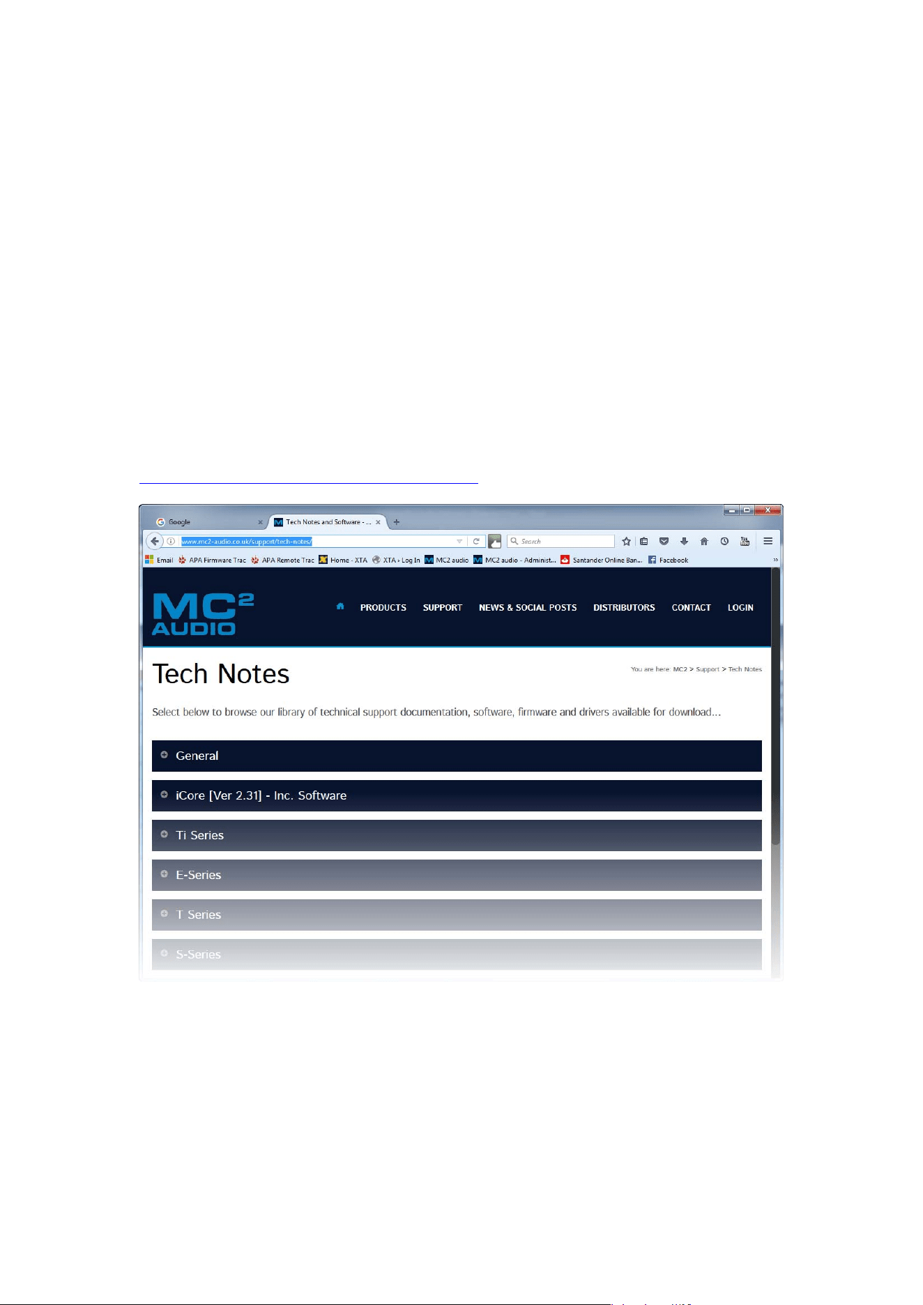
Page 82 Delta Series D40/80/100 DSP Operating Instructions
Appendix II: Upgrading Firmware and Loading Presets
Loading new firmware or presets uses the same “Flash Loader” utility that is bundled with
the firmware or presets “bin” (binary) file. Firmware (or Program) files have the prefix
“LTAM”, and preset files have the prefix “LTAR”.
Amplifier Communications Set-up
Updates c
an be performed through an Ethernet, US or RS485 connection. Choose the correct
port on the amplifier and configure it accordingly though the Interface Sub-menu. See page
51 for more info on choosing the interface.
Download th
e Files
Go to the Support > TechNotes section of the MC2 we
bsite to find the latest firmware or
presets — these will be bundled with the “Flash Loader” application that is used to connect
and update your amplifier.
http://www.mc2-audio.co.uk/support/tech-notes/
Unzip
the files — you will have the loader application, and the firmware or preset file as
appropriate.
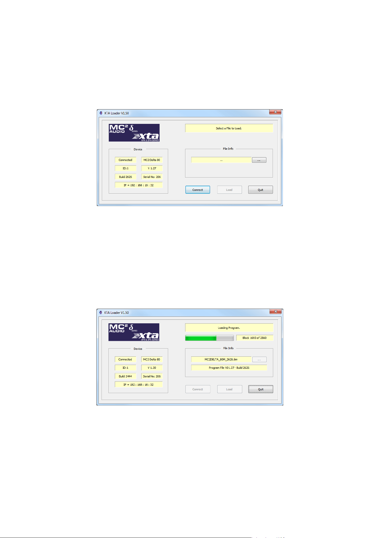
Delta Series D40/80/100 DSP Operating Instructions Page 83
Connect To The Amplifier
Plug in the appropriate cable according to your chosen connection method. Remember — if
you are connecting via an USB or RS485, you will need to make sure your amplifier is set to
ID1 for the loader to find it.
Start the loader application:
Press the “Connect” button to sca
n all USB and Etherent connections.
We recommend you choose either a USB or wired Ethernet connection, as opposed to
RS485 or wireless Ethernet.
After a few seconds, the unit should be located and its status and type should be displayed,
along with the current firmware and some other information.
Choose Wh
at To Load
Locate the firmware file by pressing the “…” button and then from the drop-down list choose
“program” (firmware).
T
he file type will have been filtered for you — LTAM*.bin for firmware (program) files or
LTAR*.bin for preset files.
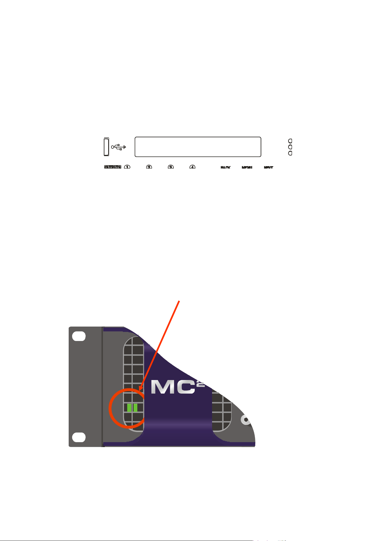
Page 84 Delta Series D40/80/100 DSP Operating Instructions
R
emo
t
e
L
oa
d
374B
Block 0 of 4096
Start The Update!
Just before you press the “Load” button — please close any other applications running on the
PC — interruptions in the process could render your amplifier inoperable. Do not disconnect
the cable, turn off the power or attempt to close the loader app once loading has begun!
Now that you have been warned (!) — press the “Load” button. Confirm the load, and the
amplifier will switch to Standby and begin to load the new firmware. A message detailing
progress will accompany the bar on the loader app:
Upon completion, the app will close and your amplifier will restart — that’s it!
What If It All Goes Wron
g…
Don’t panic! Your amplifier can be recovered, but please be aware that…
THE AMPLIFIER OPERATES AT VOLTAGES IN EXCESS OF THE INCOMING MAINS VOLTAGE,
AND THESE VOLTAGES REMAIN PRESENT FOR AN EXTENDED PERIOD AFTER MAINS
POWER IS REMOVED!
READ THESE INSTRUCTIONS CAREFULLY AND HEED ALL WARNINGS!
Disconnect your amplifier completely from the incoming mains supply.
Ensure that the HT present LEDs visible here through the front left vent with the foam
removed…
…are
fully extinguished before continuing. This will take at least five minutes so please be
patient for your own safety.
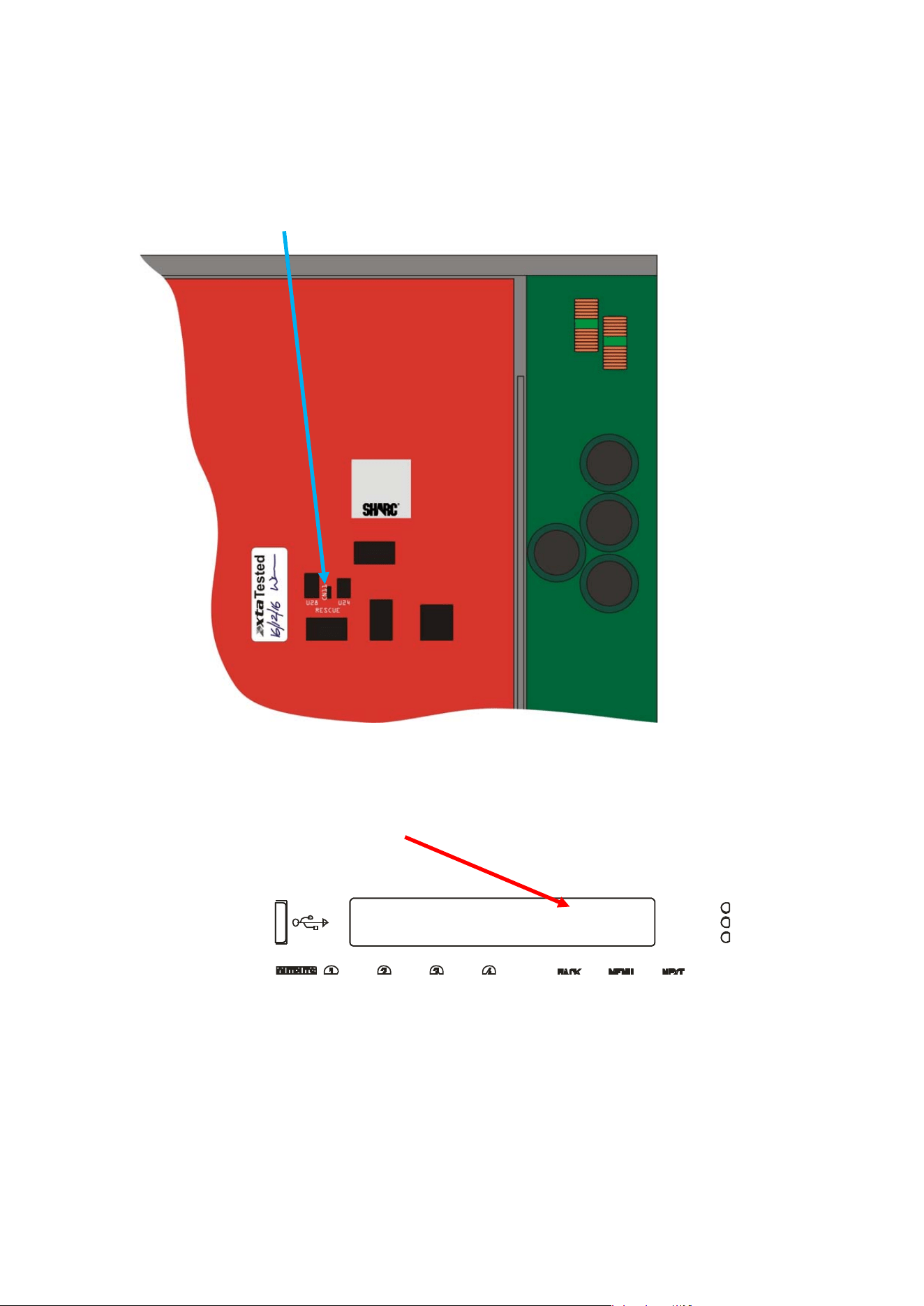
Delta Series D40/80/100 DSP Operating Instructions Page 85
Remote
L
oa
d
R374B
Block 0 of 4096
It is now safe to remove the top cover of your amplifier — there are four screws (Torx) along
each side and eight on the top of the cover. Be careful not to drop any screws inside!
Locate the “Rescue Recovery” link CN11 — between ICs U24 and U28 on the top circuit board -
and remove it. This will make your amplifier run in recovery mode — the original firmware
version loaded at the factory will now be active.
R
eplace the top cover temporarily, reapply mains power and switch on. Once booted, check
the interface is set as required and perform a program update again using the Flash Loader
application.
The display will show an additional “R” next to the Remote Load message to show rescue
mode is active:
Upon completion, the app will close. Disconnect the power and wait for at least five minutes
until the HT Present LEDs have fully extinguished again.
Remove top cover and replace the “Rescue Recovery” link once more.
Replace top cover and screw down, and replace the filter foam in the left hand front vent.
Your amplifier should now be fully operational again — no settings will have been lost in the
process.
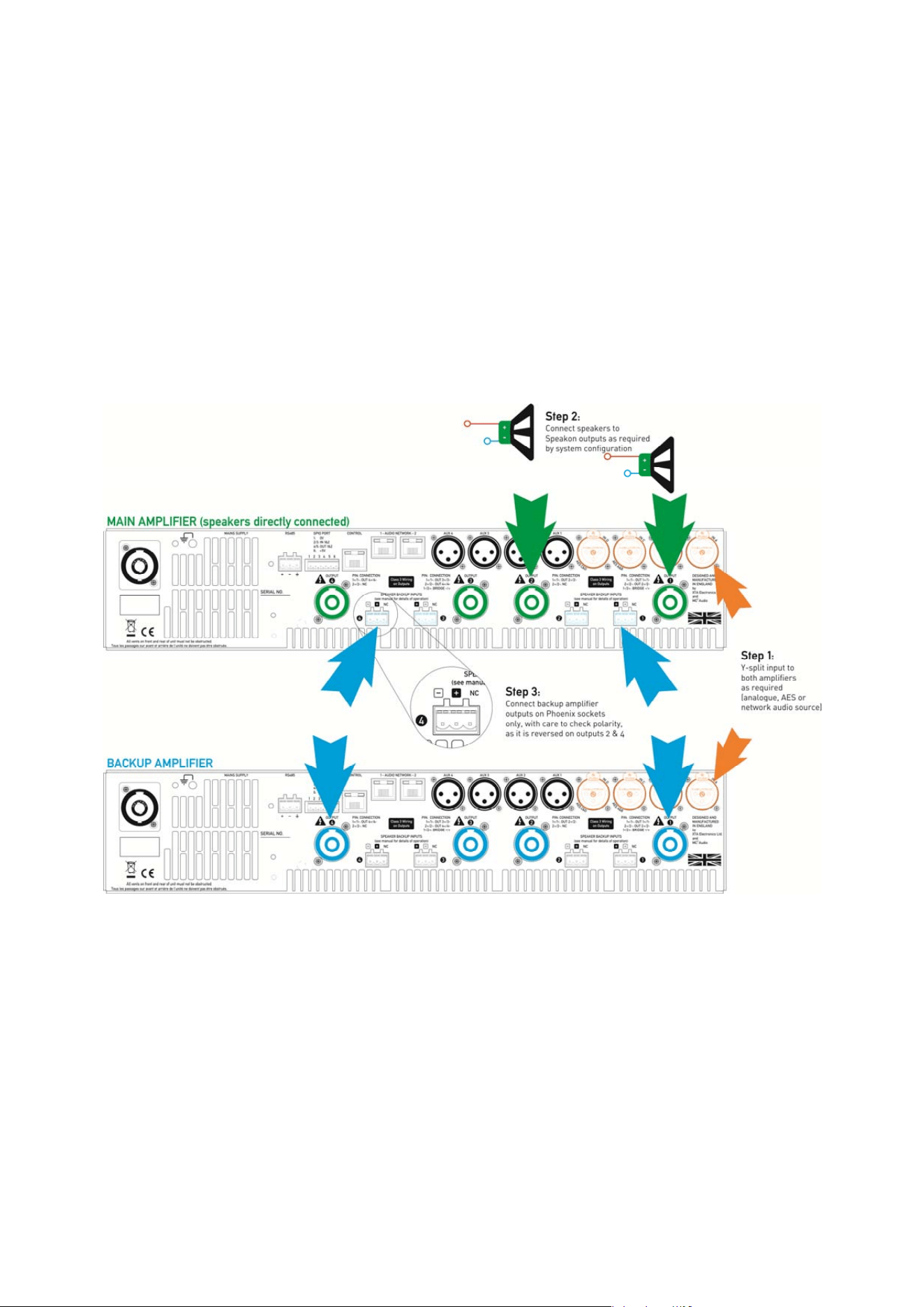
Page 86 Delta Series D40/80/100 DSP Operating Instructions
Appendix III: Speaker Backup Inputs (DSP40 Only)
It is possible to configure a secondary amplifier as a backup device for use in safety-critical
applications, which will automatically be switched into circuit should there be a failure of the
main amplifier.
Failure could include loss of power, over-temperature protection or accidental remote
enabling of standby.
To use this feature, the backup amplifier must also be a MC
2
Delta DSP 40 or XTA DPA40, or
the non-DSP equivalent (MC
2
Delta 40 or XTA DNA40). Do NOT attempt to use another
manufacturer’s amplifier or any Delta/DNA/DPA amplifier that is not fitted with this feature.
Connect the two amplifiers as shown below:
Step 1: Connect both amplifiers inputs to the required sources and make sure both amplifiers
are configured the same for routing, and source (analogue/AES/network).
Step 2: Connect speakers up the MAIN amplifier as normal in the required configuration.
Step 3: Connect link cables from the Speakon outputs of the BACKUP amplifier to the Backup
inputs of the MAIN amplifier, being careful to observe the correct polarity on the Backup
inputs which are reversed for channels 2 and 4.
Both amplifiers must remain powered up and out of standby at all times. Should the main
amplifier fail, its output relays will disengage and in doing so, connect the outputs from the
backup amplifier directly to the Speakon speaker outputs via the Phoenix inputs.