
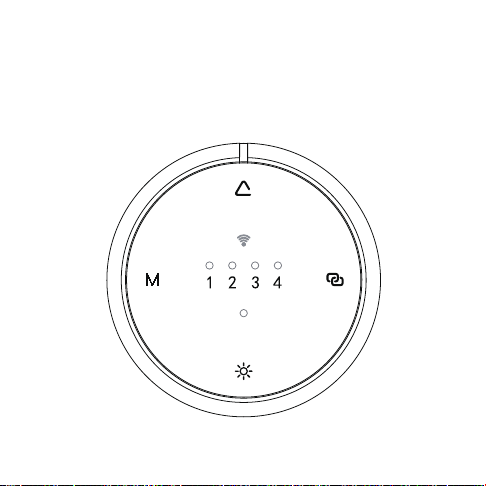
Smart Sunlight Sensor
Programming Guide
INS-101-C125
A-01 January 2026

Safety Instructions
Warning: When using this product, please note the following safety precautions:
1. Do not use a different type of battery than the one specified. Doing so can
cause a safety hazard.
2. Dispose or recycle used batteries according to your local rules and regulations.
3. Keep away from children.
4. If swallowed, seek medical attention immediately.
5. Do not:
a) Recharge non-rechargeable batteries.
b) Force discharge, recharge or disassemble batteries.
c) Do not expose batteries to temperatures below -5 ° C (23 ° F) or above 60 ° C
(140°F), as this may cause leakage or explosion resulting in burns or injury.
6. Ensure batteries are installed correctly, following indicated polarity (+ and -).
7. Do not mix old and new batteries, different brands, or different battery types
(e.g., alkaline, carbon-zinc, or rechargeable).
8. If the device will not be used for an extended period, remove the batteries and
store them properly.
9. Do not dispose of batteries in household trash or incinerate.
10. The performance of the radio system may be affected when used near devices
with strong magnetic fields or metallic surfaces. Structural conditions may also
impact range and functionality.
11. Do not operate the radio system in areas prone to high interference, such as
hospitals, airports, or other sensitive facilities.

FCC Statement
Any changes or modifications not expressly approved by the party responsible for
compliance could void the user’s authority to operate the equipment.
This device complies with Part 15 of the FCC Rules.
Operation is subject to the following two conditions:
(1) This device may not cause harmful interference, and
(2) This device must accept any interference received, including interference that may
cause undesired operation.
Note: This equipment has been tested and found to comply with the limits for a Class B
digital device, pursuant to Part 15 of the FCC Rules. These limits are designed to provide
reasonable protection against harmful interference in a residential installation. This
equipment generates, uses and can radiate radio frequency energy and, if not installed
and used in accordance with the instructions, may cause harmful interference to radio
communications. However, there is no guarantee that interference will not occur in a
particular installation. If this equipment does cause harmful interference to radio or
television reception, which can be determined by turning the equipment off and on, the
user is encouraged to try to correct the interference by one or more of the following
measures:
— Reorient or relocate the receiving antenna.
— Increase the separation between the equipment and receiver.
— Connect the equipment into an outlet on a circuit different from that to which the
receiver is connected.
— Consult the dealer or an experienced radio/TV technician for help.
FCC Radiation Exposure Statement:
This equipment complies with FCC radiation exposure limits set forth for an uncontrolled
environment.

Included
Accessories
Battery
Replacement
Mounting
Options
Installation
Considerations
2
3
4
5
01
1
Sensor
Installation
7
8
9
10
11
12
02
Sensor
Pairing
14
15
17
19
03
Sensor
Operation
Button
Location
Motor Pairing
Button Location
Pairing Sensor
to Motor
Light Levels
Ambient Light
Detection
Sensor Modes
Pairing the
Sensor Using an
Existing Remote
Shade Control
Mode Switching

01
Sensor
Installation
1
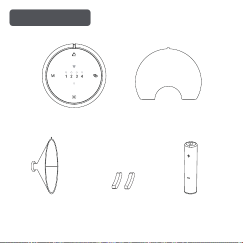
Included Accessories
2
Sensor Adhesive Tape
Suction Cup AAA Batteryspacer pad
01
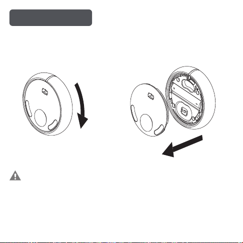
Battery Replacement
3
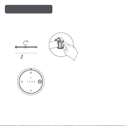
Rotate the back cover clockwise to the unlock position.
Step 1 Step 2
Note: When the battery is low, the red LED will flash once every
2 minutes. Each press of the button will also cause the red LED to
flash once. To ensure proper sensor operation, please replace
the battery promptly.
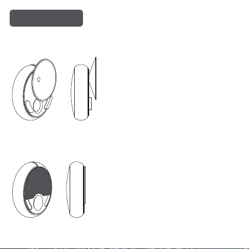
Mounting Options
4
Option 1:
Suction Cup & Spacer Installation
Option 2:
Adhesive Installation
Standard Roll Reverse Roll
5
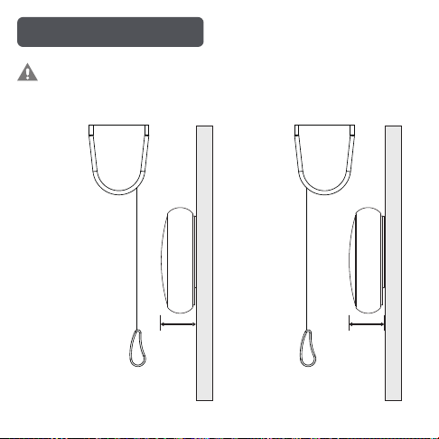
Installation Considerations
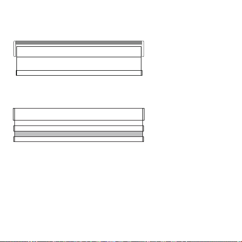
Note: To avoid Bottom Bar coming into contact with the Smart
Sunlight Sensor, follow minimum distance to window.
WINDOW
WINDOW
Adhesive Mount
23mm 23mm
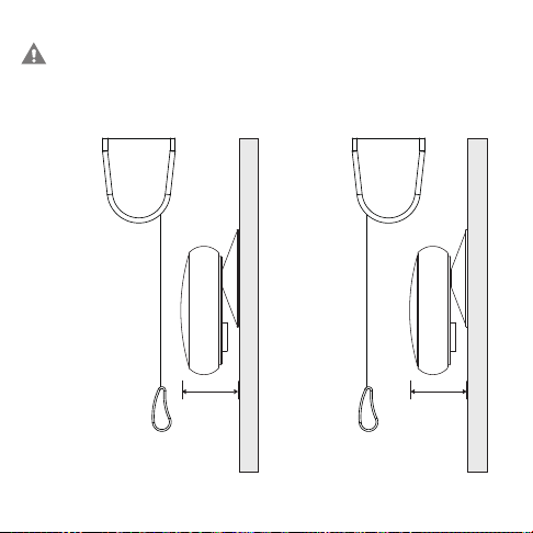
Note: To avoid Bottom Bar coming into contact with the Smart
Sunlight Sensor, follow minimum distance to window.
Standard Roll Reverse Roll
6
WINDOW
WINDOW
Suction Cup Mount
30mm
30mm

02
Sensor
Pairing
7
8
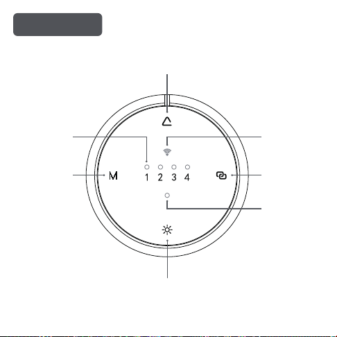
Button Location
Light/Mode
Indicator
Transmission
Indicator
Low Battery
Indicator
Up Button
Mode
Button
Stop
Button
Light Intensity
Button
02
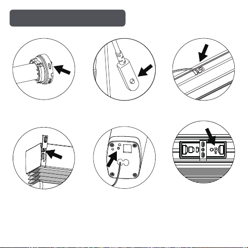
Roller Shade
9
Motor Pairing Button Location
HL
Cellular Shade
Outdoor Shade
Drapery
Cellular Shade
Skylight
10
Pairing Sensor to Motor
* Using this type of motor as an example, please refer to “Motor Pairing B
utton Location” (P9) for the specific devices.
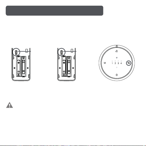
Press and hold the pairing button on the motor head for 2 seconds, until
the motor responds as below.
Activate Pairing Mode
Approx
Motor Response
2
SECS
JOG
x1
Press the Stop button on the sensor to complete the pairing.
The motor jogs twice
* Note:
For TDBU shades, after pairing is complete, please proceed to Page 12 to
switch the shade control mode.
For standard shades, the sensor is ready for use immediately after
pairing, and no shade control mode switching is required.
1. Press the "P" botton
on existing remote
for 1 second.
2. Press the "P" botton
on existing remote
again for 1 second.
3. Press and hold the
Stop button on the
sensor for 2S to
complete the pairing.
11
The motor
jogs twice
The motor
jogs once
The motor
jogs once
SETTING (P)SETTING (P)
Pairing the Sensor Using an Existing Remote
Note: Repeating this procedure on a paired sensor will disconnect
it from the motor.
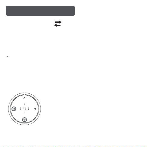
Shade Control Mode Switching
The sunlight sensor supports multiple types of motorized shades. You can
switch between two control modes to ensure proper operation with different
shade systems.
12
Standard Shade Mode TDBU Shade Mode
For standard shades, including roller shades, zebra shades, cellular shades,
and other standard shade types.
Standard Shade Mode
Factory Default Mode
1. Press and hold the MODE and SUN buttons simultaneously for 5 seconds.
Switching Control Modes
The LED corresponding to the current light level will begin flashing to indicate
the selected control mode:
2. Once the corresponding shade control mode is selected, release the buttons
to complete the mode switch.
1 flash: Standard Shade Mode (default)
2 flashes: TDBU Shade Mode
13

03
Sensor
Operation
14
03
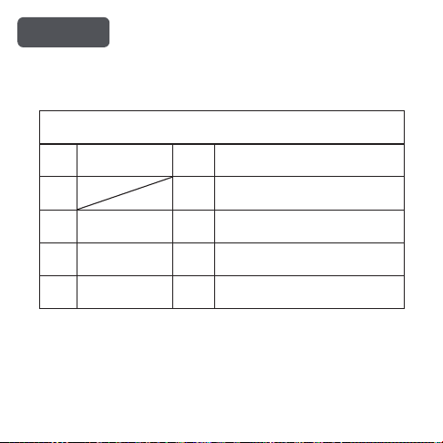
Light Levels
15
Level
Light intensity
detection range
LED Description
1 1 Sensor is off
Sensor Level Description
2 5K LUX 2
Strong light: >5,000 lux
Weak light: ≤5,000 lux
3 15K LUX 3
Strong light: >15,000 lux
Weak light: ≤15,000 lux
Strong light: >25,000 lux
Weak light: ≤25,000 lux
4 25K LUX 4
Note: The factory default setting is Level 1. When set to Level 1,
the sensor is disabled and does not detect ambient light levels.
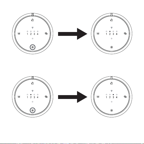
16
Press the Light Intensity
Button once
Current Light
Level is 2
Current Light
Level is 3
Checking Light Intensity
Switch the Light Level
When the indicator light
is on, press the light
function button once.
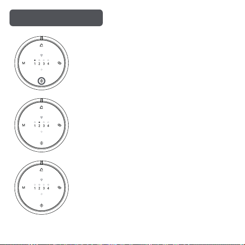
Ambient Light Detection
17
Press and hold the light function button for about 3
seconds. The Level 1 LED will remain on, indicating
that the sensor has entered ambient light detection
mode.
While in detection mode, the device will automati-
cally light up the LED corresponding to the current
ambient light level.
Press any button or remain inactive for 2 minutes
to automatically exit detection mode.
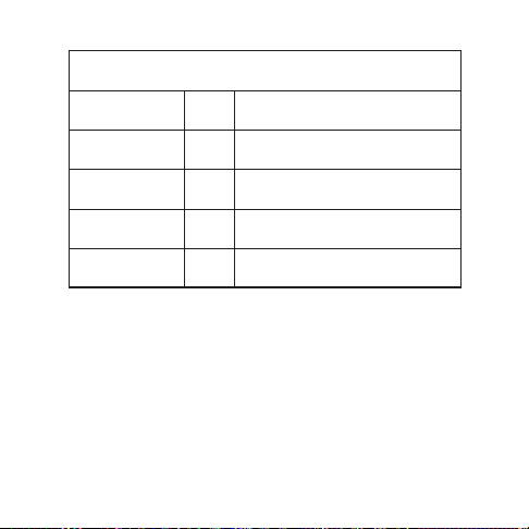
18
Ambient Light Level
LED Description
1
Current ambient light
is less than 5,000 lux
Current ambient light is
between 5,000 and 15,000 lux
Current ambient light is
between 15,000 and 25,000 lux
Current ambient light
is 25,000 lux or higher
5k-15k LUX
<5K LUX
2
15k-25k LUX 3
≥ 25k LUX 4
Ambient Light Detection Guide
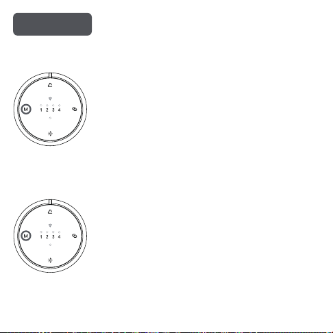
Sensor Modes
Briefly press and release the MODE button. The
LED will flash a number of times to indicate the
current mode.
(1 flash = Mode 1, 2 flashes = Mode 2, 3 flashes
= Mode 3)
Press and hold the MODE button for about 5
seconds until the LED starts flashing, then
release. The number of flashes indicates the
newly selected mode (1 flash = Mode 1, 2
flashes = Mode 2, 3 flashes = Mode 3). Repeat
this operation to cycle through the modes.
19
Press x1
Checking the Current Mode
Changing the Mode
Press and
hold for 5s
20
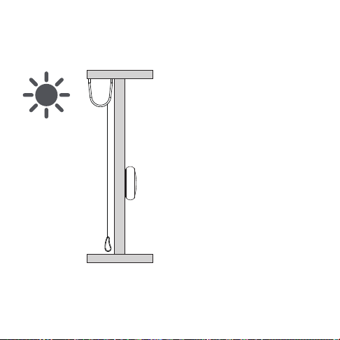
Mode 1
Application: Outdoor Shades
Mode Features: Automatic lowering only. No automatic raising.
When the ambient light remains
above the set level for 2 consecu-
tive minutes, the shades will
automatically lower (or move to
the mid-position).
When the ambient light remains
below the set level for 15 consecu-
tive minutes, the shades will
remain in their current position
and will not automatically raise.
Set the light level to the desired
level (other than Level 1).
WINDOW
21
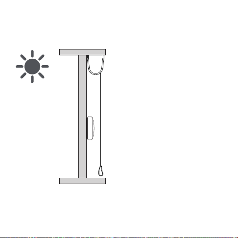
Mode 2
Application: Indoor Shades (Sensor Not Obstructed)
Mode Features: Automatic lowering and raising
Set the light level to the desired
level (other than Level 1).
When the ambient light remains
above the set level for 2 consecu-
tive minutes, the shades will
automatically lower (or move to
the mid-position).
When the ambient light remains
below the set level for 15 consecu-
tive minutes, the shades will raise.
WINDOW
22
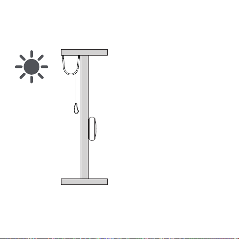
Mode 3
Application: Outdoor Shades
Mode Features: Continuously monitors light by remaining above the sensor
after lowering.
Set the light level to the desired
level (other than Level 1).
When the ambient light remains
above the set level for 2 consecu-
tive minutes, the shades will lower.
If the sensor is obstructed, the
shades will raise and stop above
the sensor.
When the ambient light remains
below the set level for 15 consecu-
tive minutes, the shades will raise.
WINDOW

- Smart Sunlight Sensor -

