Industrial Liing Equipment
2
866-207-6923
Trolleys, Beam Clamps and Towing Tractors ............................. 36
Trolley and Tractor Selection Guide
PT Series trolley – 0.50 to 10 metric ton capacities
GT Series trolley – 1 to 20 metric ton capacities
TIR Series trolley – 0.25 to 6 metric ton capacities
RT Series trolley – 1 metric ton capacity
BC Series clamp – 1 to 10 metric ton capacities
MKT Series tractor – 6 metric ton towing capacity
Contents
Electric Chain Hoists ......................................................... 28
Quantum Series — 0.125 to 5 metric ton capacities
ULE2 Ultra-Lo Series — 1 to 24 U.S. ton capacities
Air Chain Hoists .................................................................3
CLK Series - 0.125 to 0.50 metric ton capacities
MLK and HLK Series — 0.25 to 6 metric ton capacities
7700 Series and 7790 Series link chain hoists — 0.125 to 2 metric ton capacities
ISO 9001
CERTIFIED
ISO 9001
CERTIFIED
Footer 3
3
ingersollrandproducts.com/liing
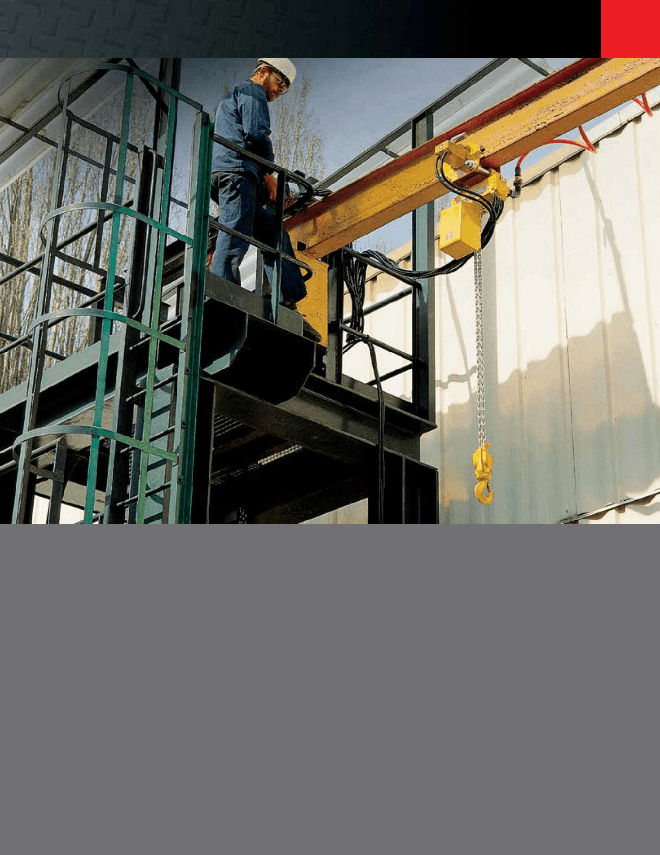
Air chain hoists are the ideal choice when high speed, high duty-cycle, precision spotting,
and the ability to operate in harsh environments are the determining factors. No one knows
air chain hoists like Ingersoll Rand.
We oer the broadest range of air chain hoists in the world. This section highlights our
oering of production hoists ranging in capacity from 0.125 to 6 metric tons.
The MLK and HLK Series hoists have proven themselves for years in the most dicult
environments. The 7700 and 7790 Series hoists are renowned for exceptional speed
and load control. The CLK Series hoist oer superior load control and low air consumption.
Our sales team and channel partners are available to help with selection, related accessories,
and options to provide the optimal solution to your liing and positioning challenges. Spare
parts and our authorized service centers are there to keep them running in peak condition.
Visit our website at www.ingersollrandproducts.com to see our high-capacity chain hoists
(up to 200 metric tons) and other products.
Air Chain Hoists
4
Air Chain
Hoists
866-207-6923
Air chain hoists selection guide
CLK SERIES
CL125K 275 0.125 1 43 13.1 37 11.3 11.5 292.1 14.1 358.1 34 15.4 6
CL250K 550 0.25 1 32 9.8 45 13.7 11.5 292.1 14.1 358.1 34 15.4 6
CL500K 1100 0.50 2 15 4.6 22 6.7 12.75 323.9 15.35 389.9 38 17.2 6
MLK SERIES AND HLK SERIES
ML250K 550 0.25 1 101 30.8 117 35.7 18 457.2 18 457.2 48 21.8 10
ML250KS 550 0.25 1 40 12.2 90 27.4 18 457.2 18 457.2 48 21.8 10
ML250KR 550 0.25 1 26 7.9 38 11.6 18 457.2 18 457.2 48 21.8 10
ML500K 1,100 0.5 1 55 16.8 97 29.6 18 457.2 18 457.2 48 21.8 10
ML500KS 1,100 0.5 1 22 6.7 66 20.1 18 457.2 18 457.2 48 21.8 10
ML500KR 1,100 0.5 2 13 4 20 6.1 18 457.2 18 457.2 61 27.7 10
ML1000K 2,200 1 2 28 8.5 49 14.9 18 457.2 18 457.2 61 27.7 10
ML1000KS 2,200 1 2 11 3.4 33 10.1 18 457.2 18 457.2 61 27.7 10
HL1000K 2,200 1 1 26 7.9 37 11.3 18.5 469.9 18.1 460.5 84 38.1 10
HL1000KR 2,200 1 1 26 7.9 37 11.3 18.5 469.9 18.1 460.5 84 38.1 10
HL1500K 3,300 1.5 1 16 4.9 26 7.9 18.8 477.5 18.9 479.5 84 38.1 10
HL2000K 4,400 2 2 13 4 18 5.5 23 584.2 21.6 549.4 125 56.7 10
HL3000K 6,600 3 2 8 2.4 13 4 25 635 22.6 574.8 125 56.7 10
HL4500K 10,000 4.5 3 4.6 1.4 10 3.1 30.9 784.4 28 711.2 193 87.5 10
HL6000K 13,200 6 4 3.5 1.1 7.6 2.3 36.2 919.2 32.2 817.6 248 112.5 10
ARO SERIES
7770E 275 0.125 1 110 33.5 275 83.8 17 432 16.9 428 41 18.6 19
7718E 550 0.25 1 82 25 224 68.3 17 432 16.9 428 41 18.6 19
7756E 1,100 0.5 1 41 12.5 112 34.1 17 432 16.9 428 41 18.6 19
7776E 2,200 1 2 21 6.4 56 17.1 21.7 551 20.5 521 53 24 19
7790A 2,200 1 1 26 7.9 44 13.4 18.9 479 15 381 62 28.1 19
7792A 4,400 2 2 12 3.7 24 7.3 22.4 568 18 457 81 36.7 19
7712EL 550 0.25 1 50 15.2 70 21.3 17 432 17.1 435 41 18.6 19
7714EL 1,500 0.68 2 16 4.9 16 4.9 17 432 17.1 435 41 18.6 19
7796AL 1,500 0.68 1 16 4.9 16 4.9 18.9 479 15 381 62 28.1 19
7798AL 2,400 1.1 2 12 3.7 12 3.7 22.4 568 18 457 81 36.7 19
7799AL 3,000 1.36 2 7 2.1 7 2.1 22.4 568 18 457 81 36.7 19
Model
Liing Capacity
# Falls
Liing Speed
Rated Load
Lowering Speed
Rated Load
Hook Mount
Headroom
Trolley Mount
Headroom
Shipping Weight
Top Hook
Page No.lb
metric
tons /min m/min /min m/min in mm in mm lb kg
All Ingersoll Rand Series hoists meet or exceed ASME/ANSI B30.16 standards. Please consult factory for hoists that meet the European machinery directive (EC) and carry the CE mark.
Footer 5
5
Air Chain
Hoists
ingersollrandproducts.com/liing
Choosing the right hoist
Material handling needs dier from application to
application. Ingersoll Rand oers numerous hoist
types with a range of options that can be matched
to meet your specific requirements. When the time
comes to select the appropriate hoist for your needs,
consider the following criteria:
Maximum load
Consider the maximum load the hoist will need
to accommodate. Ingersoll Rand hoists have weight
ratings from 275 lb to 6 tons. Consider hoist speed.
The speed requirement of a hoist is dependent
on the corresponding cycle time of the task to be
performed – li, transport, lower, return, start again.
Installation requirements
Ingersoll Rand hoists, whether hook or trolley, can be
mounted on several beam configurations. Compact
for low headroom requirements, these hoists can be
mounted in areas where others can’t.
Air supply
To ensure maximum operating performance,
Ingersoll Rand rotary-vane air hoists require air
supplies that continually provide clean, lubricated
air at sucient pressure and volume. Ingersoll Rand
hoists require 90 psig at 32 to 70 scfm.
Control method
Our rotary-vane air hoists control li and descent
by admitting proportional amounts of air to the
motor through a valve. Ingersoll Rand oers two
control systems:
1. Pendent control system — a 3-hose pilot
pressure / bleed system opens and throttles
the valve.
2. Pull-chain system — operator-controlled
pull chains attached to arm open and close
the valve.
6
Air Chain
Hoists
866-207-6923
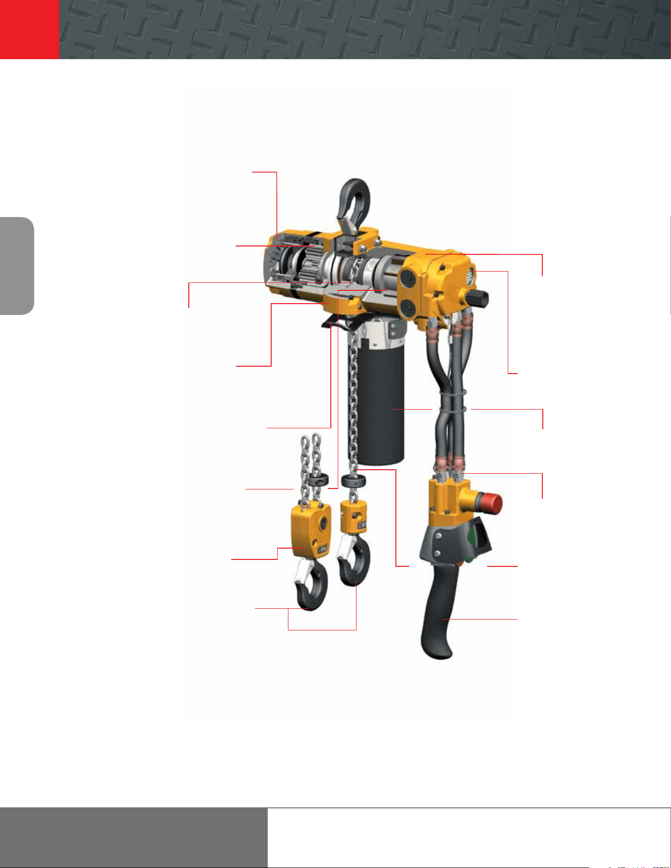
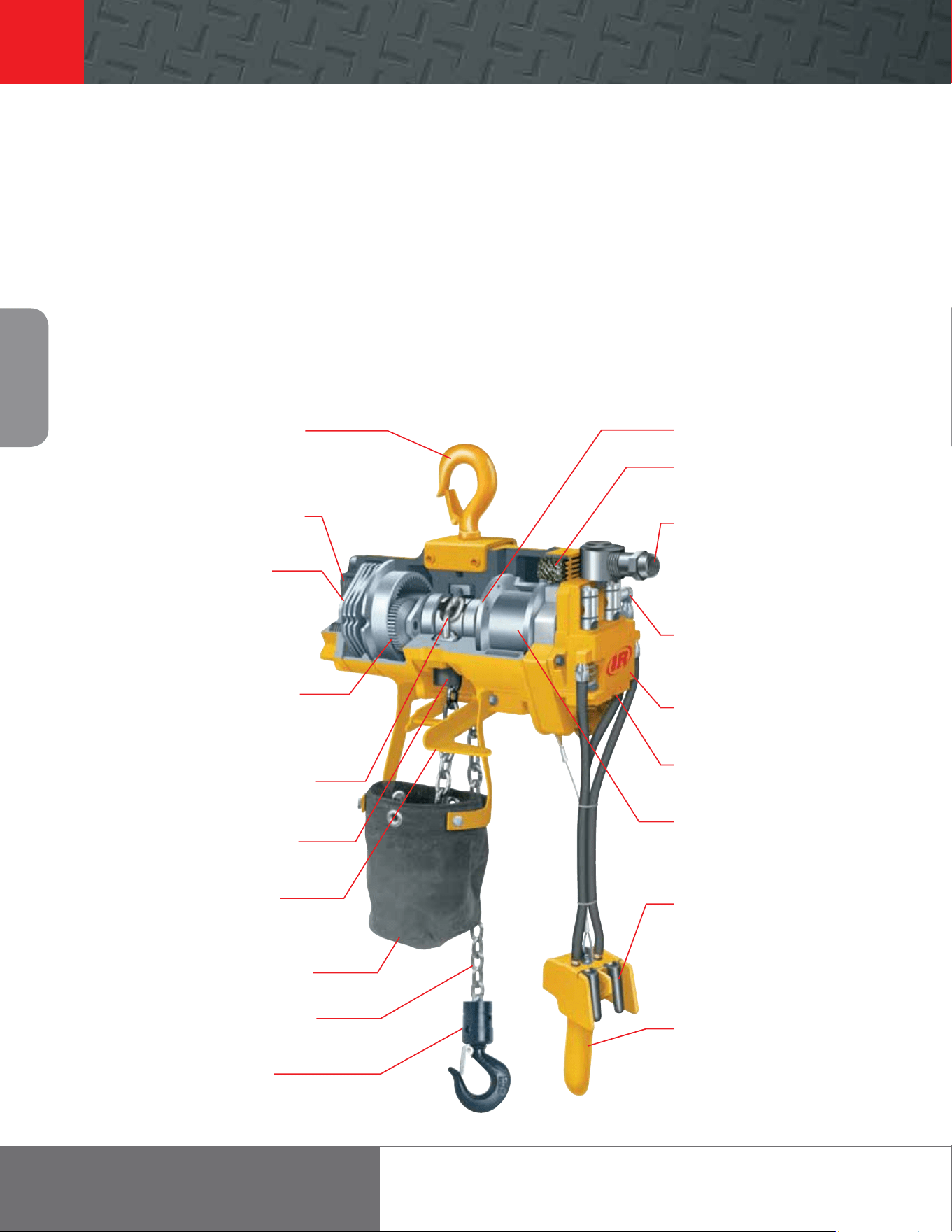
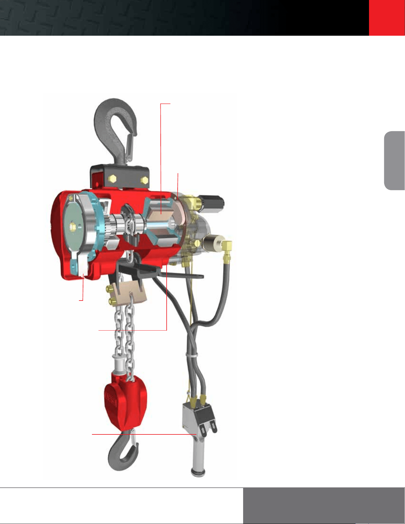
Disc brake is non-asbestos and spring-engaged
with an air release that oers significant control
while minimizing air consumption.
A two-stage dierential transmission
multiplies motor torque and reduces speed.
Oil lubrication helps create maximum durability.
Gearing components are made from high-strength,
heat-treated steel alloy.
Forged five-pocket pocket wheel provides for
smooth lis and enhanced chain life.
Specially designed slack chain opening
prevents dangerous cross-linking by
guiding chain to the drive wheels.
Upper and lower limit stops prevent dangerous
over-travel of the hook in either direction,
reducing possible damage to hoist and load.
100% duty cycle multi-vane (6) air motor
oers a high-torque and low-maintenance design.
Air porting under the vanes creates smooth
operation, positive starting, and long life.
Double reeving is used on 500-kilogram
units only.
Bottom latch-type swivel hooks meet OSHA
requirements and are supported by anti-friction
needle type thrust bearings.
High-strength aluminum
housing for maximum
portability and weather
resistance. Strong yet light-
weight with a durable powder-
coated finish.
Internal muer reduces sound
levels to a best-in-the-industry
75 dBA.
Optional fabric chain
container (available at extra
cost) helps keep slack chain
out of the way.
Full flow pendent for maximum
control and enhanced load
positioning capabilities.
Standard link load chain is
zinc-plated steel DAT grade 80.
Ergonomic pendent handle
(shown with optional E-stop)
is rugged and durable. Guard
covers both levers and can be
used with or without gloves.
Optional E-stop (available at
extra cost) makes this hoist
CE-compliant.
CLK Series
Pneumatic hoists: 125-, 250-, and 500-kg models
Footer 7
7
Air Chain
Hoists
ingersollrandproducts.com/liing
CLK Series
Pneumatic hoists: 125-, 250-, and 500-kg models
CLK Series Specifications
Model
Capacity
# Falls
Hook Mount
Headroom
Trolley Mount
Headroom
Liing Speed
Lowering Speed
Chain
Size
Chain Weight
(per foot of li)
Net Weight
w/10 of Li
kg
Rated Load No Load Rated Load No Load
lb in mm in mm /min m/min /min m/min /min m/min /min m/min lb kg lb kg
CL125K 275 125 1 11.5 292.1 14.1 358.1 43 13.1 56 17.1 37 11.3 27 8.2 4 x 12 0.24 0.11 34 15.4
CL250K 550 250 1 11.5 292.1 14.1 358.1 32 9.8 56 17.1 45 13.7 27 8.2 4 x 12 0.24 0.11 34 15.4
CL500K 1100 500 2 12.75 323.9 15.35 389.9 15 4.6 26 7. 9 22 6.7 13 4.0 4 x 12 0.48 0.22 38 17.2
Working pressure from 5 to 7 bar (70 to 100 psi). Air consumption @ rated load — all models 0.9 m (32 cfm). Air inlet 3/8” NPT. Sound level 75 dBA.
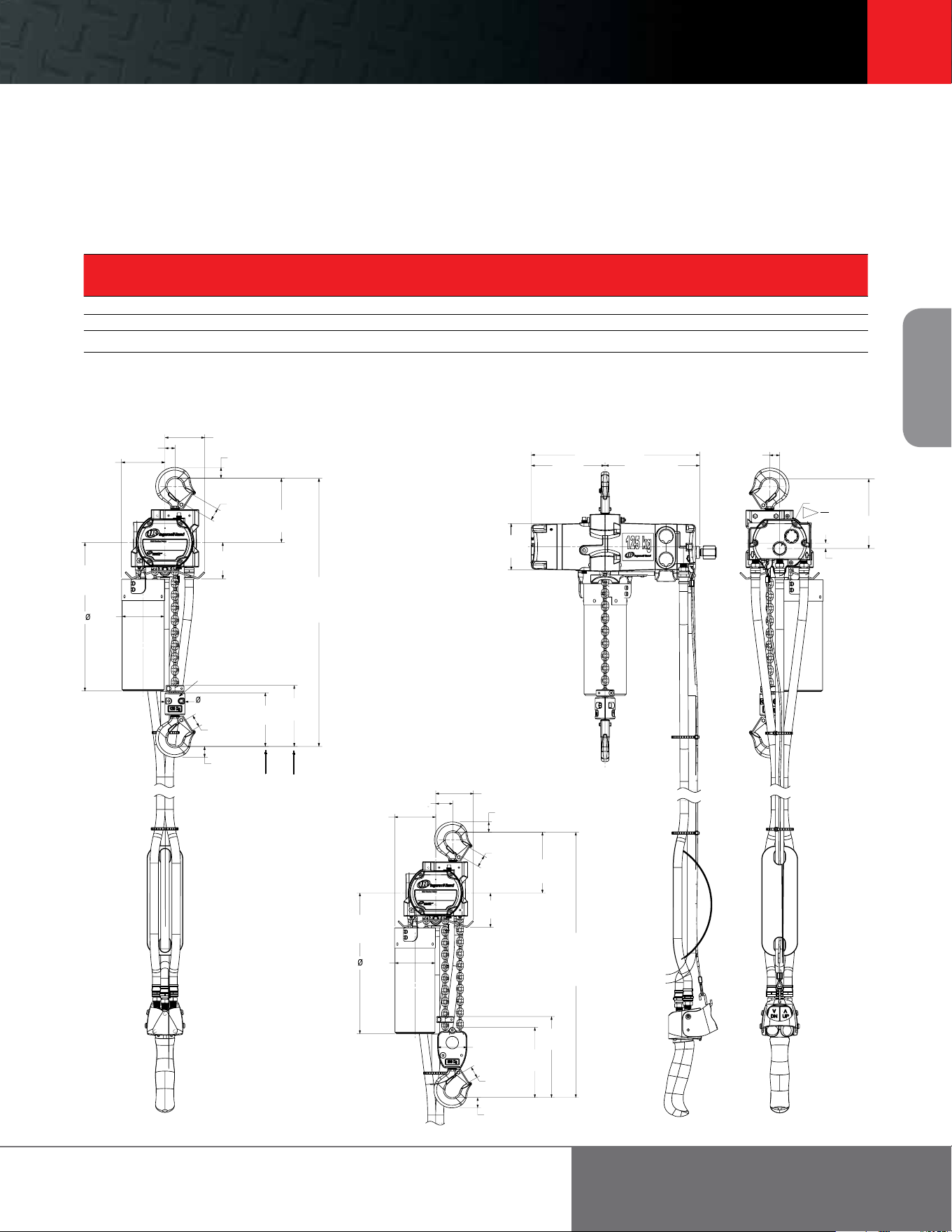
CL125K and CL250K
76.9 [3.03]
21.0 [.83]
19.5 [.77]
83.7 [3.30]
20.0 [.78]
70.0
[2.76]
292.1
[11.50]
minimum head room
w/o chain stop
123.8
[4.87]
286.8
[11.29]
81.4
[3.20]
117.9
[4.64]
103.7
[4.08]
38.3 [1.51]
20.0 [.78]
21.0 [.83]
34.7 [1.37]
59.3 [2.34]
155.6
[6.13]
143.1
[5.63]
19.5
[.77]
Hoist Inlet
134.5
[5.30]
NPT
10.7
[.42]
H
3
8
182.4 [7.18]
324.8 [12.79]
142.3 [5.60]
89.7
[3.53]
34.7
[1.37]
76.9 [3.03]
21.0 [.83]
20.0 [.78]
123.8
[4.87]
70.0
[2.76]
323.9
[12.75]
minimum head room
w/o chain stop
34.7 [1.37]
83.7 [3.30]
286.8
[11.29]
81.4
[3.20]
20.0 [.78]
21.0 [.83]
59.3 [2.34]
155.6
[6.13]
143.1
[5.63]
CL500K
CL125K and CL250K
8
Air Chain
Hoists
866-207-6923
Accessories
Pneumatic hoists: 125-, 250-, and 500-kg models
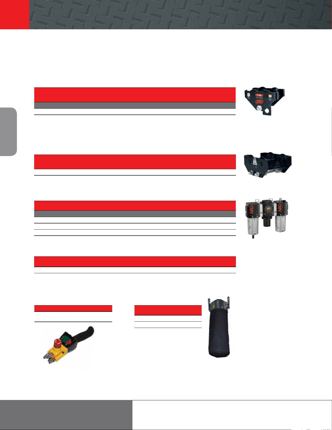
PT Series Hook-on Trolley
Model
Capacity
Flange
Adjustment
Min. Beam
Height
Min. Curve
Radius Weight Kit no.
Flange
Adjustment Weight
lb metric tons in in in lb (order separate) in lb
STANDARD SERIES
PT005-8 1,100 0.50 2.6 – 8 4 36 19.7 PT005-WFK 8 – 13 5.5
Wheels are cast iron and the universal tread fits either flat or tapered beams.
PT005-8
RT010 Series Trolley
Fits Beam Minimum
Trolley Capacity Flange Width Turning Radius
Part Number metric tons in in
RT010 0.25 - 1 2.7 - 6 36
Wheels have universal tread for use on flat or tapered beams.
Filters - Regulators - Lubricators
Size (in) Flow Rate Adj. Pressure Range Bowl Capacity Height x Width
Part No.
NPTF scfm psig oz in
TRIO UNITS: FILTERS, REGULATORS, LUBRICATORS
C38341-810 1/2 150 5 – 250 4 6 x 8.7
C38451-810 3/4 200 5 – 250 4 8.6 x 11.1
C38461-810 1 215 5 – 250 4 8.6 x 11.1
C38341-810
Quick Exhaust Valves
Part For Use Control Pendent Length
Number With Type Style
MR-939 All CLK Series Full-flow 3/8” NPT 15 – 40
The first pair of full-flow valves will be installed between 7 and 8 from the pendent handle aer pendent hose length reaches 16 .
Any additional valves will equally divide the remaining hose length.
Link Chain Canvas Basket
Capacity
Part No.
CL250K-749-20 20
CL250K-749-40 40
E-Stop Pendent Handle
Part Number Description
45667359 Pendent handle assembly with
E-stop function
Cousin to the PT Series trolley, the twin suspension sha RT Series trolley oers a rigid connection
for the CLK Series of air chain hoists. Lug adapter CL250K-425 is required for use with the RT trolley.
E-Stop Pendent
Handle
Link Chain
Canvas Basket
Footer 9
9
Air Chain
Hoists
ingersollrandproducts.com/liing
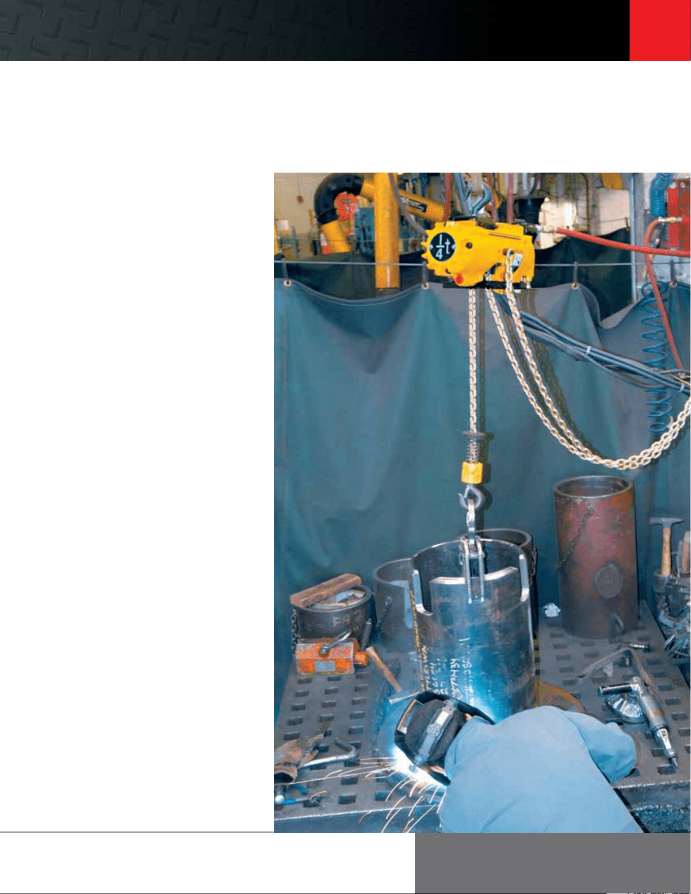
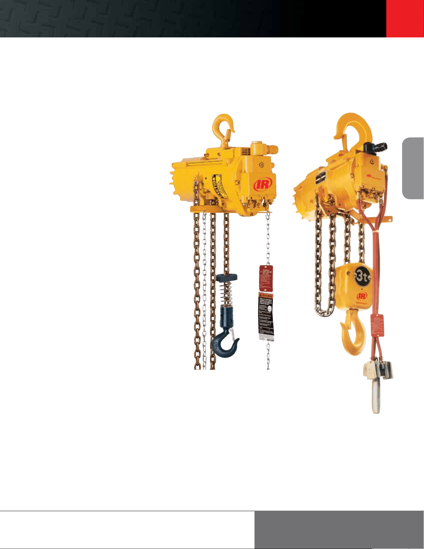
Ingersoll Rand, the most trusted name for quality, high-value
hoists, introduces the CLK Series, including 125-, 250- and
500-kilogram models.
Industry-leading durability, precision,
and flexibility
The CLK Series is the smart choice for:
uDurability that delivers more uptime — With a FEM/ISO mechanism classification of
1Am/M4 (ASME HST-5 rating of A5), CLK Series hoists are duty-rated to go an incredible
800 full-load hours between overhauls.
u Liing speed and precision control for enhanced ease of use — Liing speed of 43 fpm
(13.1m/min) for the 125 kg models and 32 fpm (9.8m/min) for the 250 kg models is the
best in its class. Enhanced load “positioning” capabilities and an outstanding combination
of motor control and brake release make this hoist ideal for precision applications.
u “Best-in-the-industry” quiet operation enhances safety and decreases operator fatigue —
Sound levels of just 75 dBA make CLK Series hoists easy on operators, while also minimizing
the overall ambient noise of the work site.
u Highly ecient air motor saves money — For hoists in its class, CLK Series gets the most
performance from your compressed air output. The CLK Series consumes only 32 cfm
(0.9 m
3
/min) of air liing rated load and less then 16 cfm (0.5 m
3
/min) while lowering load.
For more
information on how the
CLK Series hoists can
generate high return on
your equipment
investment:
See your local
distributor
Call 866-207-6923
Visit
ingersollrandproducts.com
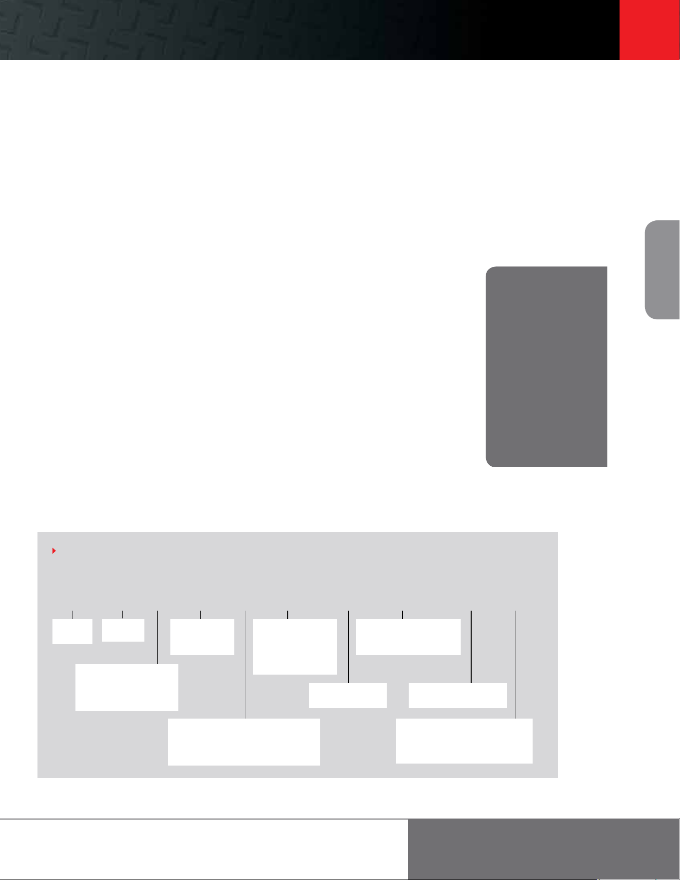
Example: CL250K-2C10-C6U
C L 250K – 2 C 10 – C 6 U - E
Suspension
A = Fixed lug (adapts to RT010A trolley)
C = Top hook
DA = Plain rigid trolley
Capacity
125K = 125 kg = 275 lb
250K = 250 kg = 550 lb
500K = 500 kg = 1,100 lb
Lower hook
C = Steel snap hook
HOW TO ORDER
Specify hoist by complete model number code as illustrated below. Specify accessories separately by part number. Note that 0 is a number, not a letter,
in model part numbers.
Options
U = Fabric chain container
CE Package
E = Compliance with the European
Machinery Directive – will
include E-stop pendent control
Pendent Control Hose ()
6 = 6
40 max. pendent hose length
Li ()
10 = 10
200 max. - CL125K &
CL250K
100 . max. - CL500K
Control
0 = No Pendent
2 = Pendent
Link chain
type
Series
C = Series
10
Air Chain
Hoists
866-207-6923
MLK and HLK Series
0.25 to 6 metric ton liing capacities
Benefits
• 100 percent duty cycle enables continuous operation
• Dust, dirt, moisture, and corrosive gases kept out of
the motor by air pressure — ideal for foundries and
electro-plating applications
• Minimum chance of electrical shock makes air hoists
ideal for highly flammable environments such as
chemical plants and refineries; spark-resistant models
also available
• Simple pull-chain speed and directional controls provide
precise load-spotting capabilities; easy-to-operate pendent
air valves provide a variable control signal with adjustable
response by a variable orifice. For more precise control, MLKS
slow-speed models are available.
• Motor, brake, and throttle parts are interchangeable
with all current Ingersoll Rand air chain hoists
• Ingersoll Rand air chain hoists are designed and constructed
for trouble-free maintenance
Top and bottom latch-type swivel hooks
meet OSHA requirements and are supported
by anti-friction roller bearings (Bullard
Burnham hooks are available for all models,
except spark-resistant)
All bearings are either ball- or roller-
type to minimize friction
An internal muer reduces sound
levels to 85 dBA; woven to prevent
corrosion and clogging
Inlet swivel and strainer are
combined for easy hookup from any
direction — swivel reduces hose
fatigue, especially on hook-mounted
units; strainer nipple provides extra
assurance of clean air for maximum
wear protection
Precision throttle valves for
smooth operation and metering of
air; valves are poppet-type for ease of
maintenance
Control adjustment screws provide
sensitivity and maximum speed control
for pendent models
Pilot pendent control provides a
variable pressure signal to the valve
chest, where flow to hoist is metered
accordingly; air does not travel
through pendent, thus pendent length
does not aect performance; control
hoses are small, flexible, and easily
converted to dierent lengths
One-piece, cast-aluminum
guarded pendent handle for
maximum durability; guards on
either side of levers are cast-in
for protection against accidental
operation; all functional parts are
corrosion- and spark-resistant
Two-piece, single-line hook block entraps
chain links and hook bearing without using
small load-bearing pins or fasteners
Standard link load chain is zinc-plated steel;
stainless steel chain available for 0.25-ton
through 1-ton spark-resistant models
Fabric or metal container keeps slack chain
out of the way
Upper and lower limit stops prevent
dangerous over-travel of the hook in either
direction, reducing possible damage to hoist
or load
Slack chain is guided into drive wheels by
a specially designed opening that prevents
dangerous cross-linking
A small amount of exhaust air flows over chain
and drive wheel to help lubricate chain from
spent in-line lubrication of motor
Air-operated, non-asbestos, self-
adjusting disc brake balances eort to
motor torque by sensing air pressure in the
valve chest, providing precise control and
eliminating back-drop encountered with some
mechanical brakes; if air supply is interrupted,
pressure release causes instantaneous,
automatic braking
Heat-treated planetary gearing system
provides high-torque capability by splitting the
torque path, thereby dividing and balancing
the load over more teeth, assuring longer life
and reduced maintenance
High-strength aluminum housing
is strong yet lightweight for maximum
portability and weather resistance
Manual brake release kit allows operators
to safely lower a suspended load in a power
failure
100 percent duty-cycle multi-
vane motor with high torque, low
maintenance design, and air porting
under vanes for smooth operation,
positive starting, and long life
Footer 11
11
Air Chain
Hoists
ingersollrandproducts.com/liing
MLK Series and HLK Series
0.25 to 6 metric ton liing capacities
Features
MLK Series
The Ingersoll Rand MLK family of hoists is suitable
for A5 / H5 severe-duty use in the 0.25 to 1 metric ton
range. The MLK Series is designed to be used as a high-
speed production hoist; the MLKS* is better suited
for slow-speed spotting.
HLK Series
The HLK Series incorporates a larger chain wheel to
accommodate 3/8” diameter chain and a lower gear
ratio to handle increased load capacities. HLK Series
hoist capacities range from 1 to 6 metric tons and are
severe-duty rated. Refer to the trolley section on
page 61 for plain, geared, and motorized trolleys.
Spark-resistant features
MLKR and HLKR spark-resistant hoists have been
designed to give maximum protection in explosive
and other hazardous environments.
Components for spark-resistance include:
• Bronze hooks
• Bronze trolley wheels
• Stainless-steel (one part reeving) or aluminum
(two parts reeving) lower hook blocks
• Aluminum stop ring (1/4-ton models)
• Stainless-steel load chain
• Stainless-steel pendent levers and bronze
valve caps
The load capacity and speeds of MLKR and HLKR
Series units are reduced. A restricted motor is used
to accomplish this, as stainless-steel chain is not
hardened and strength is less than standard
alloy chain.
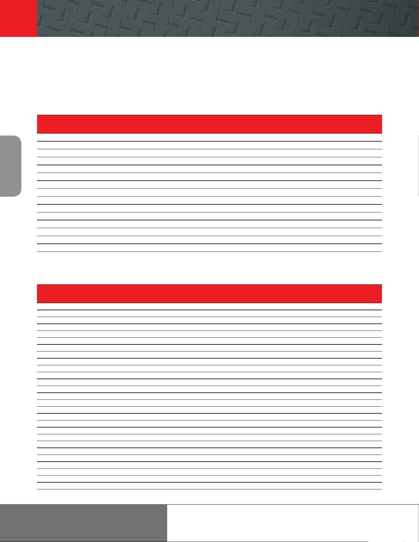
MLK Series HLK Series
12
Air Chain
Hoists
866-207-6923
MLK and HLK Specifications (performance at 90 psi, 6.3 bar)
Model
Capacity
# Falls
Hook Mount
Headroom
Trolley Mount
Headroom
Liing Speed
Lowering Speed
Chain
Size
Chain Weight
(per foot of li)
Net Weight
w/10 of Li
metric
tons
Rated Load No Load Rated Load No Load
lb in mm in mm /min m/min /min m/min /min m/min /min m/min lb kg lb kg
ML250K 550 0.25 1 18 457.2 18 457.2 101 30.8 171 52.1 117 35.7 99 30.2 6.4 x 19.5 0.6 0.3 48 21.8
ML250KS 550 0.25 1 18 457.2 18 457.2 40 12.2 71 21.6 90 27.4 53 16.2 6.4 x 19.5 0.6 0.3 48 21.8
ML250KR 550 0.25 1 18 457.2 18 457.2 26 7.9 42 12.8 38 11.6 30 9.1 6.4 x 19.5 0.6 0.3 48 21.8
ML500K 1,100 0.50 1 18 457.2 18 457.2 55 16.8 106 32.3 97 29.6 59 18 6.4 x 19.5 0.6 0.3 48 21.8
ML500KS 1,100 0.50 1 18 457.2 18 457.2 22 6.7 44 13.4 66 20.1 32 9.8 6.4 x 19.5 0.6 0.3 48 21.8
ML500KR 1,100 0.50 2 18 457.2 18 457.2 13 4 21 6.4 20 6.1 15 4.6 6.4 x 19.5 1.1 0.5 61 27.7
ML1000K 2,200 1 2 18 457.2 18 457.2 28 8.5 53 16.2 49 14.9 30 9.1 6.4 x 19.5 1.1 0.5 61 27.7
ML1000KS 2,200 1 2 18 457.2 18 457.2 11 3.4 22 6.7 33 10.1 16 4.9 6.4 x 19.5 1.1 0.5 61 27.7
HL1000K 2,200 1 1 18.5 469.9 18.1 459.7 26 7.9 40 12.2 37 11.3 26 7.9 9.5 x 25.7 1.3 0.6 84 38.1
HL1000KR 2,200 1 1 18.5 469.9 18.1 459.7 26 7.9 40 12.2 37 11.3 26 7.9 9.5 x 25.7 1.3 0.6 84 38.1
HL1500K 3,300 1.50 1 18.8 477.5 18.9 480.1 16 4.9 28 8.5 26 7.9 16 4.9 9.5 x 25.7 1.3 0.6 84 38.1
HL2000K 4,400 2 2 23 584.2 21.6 548.6 13 4 20 6.1 18 5.5 13 4 9.5 x 25.7 2.6 1.2 125 56.7
HL3000K 6,600 3 2 25 635 22.6 574 8 2.4 14 4.3 13 4 8 2.4 9.5 x 25.7 2.6 1.2 125 56.7
HL4500K 9,900 4.50 3 30.9 784.9 28 711.2 4.6 1.4 10.5 3.2 10 3.1 6.6 2 9.5 x 25.7 3.9 1.8 193 87.5
HL6000K 13,200 6 4 36.2 919.5 32.2 817.9 3.5 1.1 8.4 2.6 7.6 2.3 4.8 1.5 9.5 x 25.7 5.2 2.4 248 112.5
Working pressure from 5 to 7 bar (70 to 100 psi). Air Consumption @ rated load - ML250KS, ML250KR, ML500KS,ML500KR, ML1000KS = 1.27m³ (45 cfm) all other models = 1.98m³ (70 cfm).
Air inlet 1/2” NPT. Sound level 85 dBA.
Trolley Mount Specifications
Model
Trolley
type
Capacity
metric tons
Minimum
Headroom
Trolley Speed at
Rated Load
Air Consumption @
Rated Load
Trolley Flange
Adjustment
Minimum Curve
Radius Air Inlet
Net Weight
w/10 of Li
in mm /min m/min
3
/min m
3
/min in mm m lb kg
ML250K, KS, KR Plain 0.25 18 457 - - - - 2.66-12 68-305 3.5 1.1 - 68 31
Geared 0.25 18 457 - - - - 2.66-12 68-305 3.5 1.1 - 71 32
Motor 0.25 18 457 95 29 35 1 2.66-12 68-305 3.5 1.1 1/4 78 35
ML500K, KS, KR Plain 0.50 18 457 - - - - 2.66-12 68-305 3.5 1.1 - 68 31
Geared 0.50 18 457 - - - - 2.66-12 68-305 3.5 1.1 - 71 32
Motor 0.50 18 457 95 29 35 1 2.66-12 68-305 3.5 1.1 1/4 78 35
ML1000K, KS Plain 1 17 432 - - - - 2.66-12 68-305 3.5 1.1 - 81 37
Geared 1 17 432 - - - - 2.66-12 68-305 3.5 1.1 - 84 38
Motor 1 17 432 93 28 35 1 2.66-12 68-305 3.5 1.1 1/4 91 41
HL1000K, KR Plain 1 18 457 - - - - 3.25-12 83-304 3.5 1.1 - 106 48
Geared 1 18 457 - - - - 3.25-12 83-304 3.5 1.1 - 109 50
Motor 1 18 457 93 28 35 1 3.25-12 83-304 3.5 1.1 1/4 116 53
HL1500K Plain 1.50 18 457 - - - - 3.25-12 83-304 3.5 1.1 - 106 48
Geared 1.50 18 457 - - - - 3.25-12 83-304 3.5 1.1 - 109 50
Motor 1.50 18 457 84 25 35 1 3.25-12 83-304 3.5 1.1 1/4 116 53
HL2000K Plain 2 22 559 - - - - 3.25-12 83-304 3.5 1.1 - 203 92
Geared 2 22 559 - - - - 3.25-12 83-304 3.5 1.1 - 206 94
Motor 2 22 559 80 24 35 1 3.25-12 83-304 3.5 1.1 1/4 213 97
HL3000K Plain 3 23 584 - - - - 3.25-12 83-304 3.5 1.1 - 203 92
Geared 3 23 584 - - - - 3.25-12 83-304 3.5 1.1 - 206 94
Motor 3 23 584 71 22 35 1 3.25-12 83-304 3.5 1.1 1/4 213 97
HL4500K Plain 4.50 27 686 - - - - 4.25-7.25 108-184 5 1.5 - 392 178
Geared 4.50 27 686 - - - - 4.25-7.25 108-184 5 1.5 - 395 180
Motor 4.50 27 686 60 18 35 1 4.25-7.25 108-184 5 1.5
1/4 402 182
HL6000K Plain 6 29 737 - - - - 4.25-7.25 108-184 5 1.5 - 442 201
Geared 6 29 737 - - - - 4.25-7.25 108-184 5 1.5 - 445 202
Motor 6 29 737 45 14 35 1 4.25-7.25 108-184 5 1.5 1/4 452 205
Working pressure from 5 to 7 bar (70 to 100 psi).
MLK and HLK Series
0.25 to 6 metric ton liing capacities
Footer 13
13
Air Chain
Hoists
ingersollrandproducts.com/liing
MLK and HLK Specifications (performance at 90 psi, 6.3 bar)
Model
Capacity
# Falls
Hook Mount
Headroom
Trolley Mount
Headroom
Liing Speed
Lowering Speed
Chain
Size
Chain Weight
(per foot of li)
Net Weight
w/10 of Li
metric
tons
Rated Load No Load Rated Load No Load
lb in mm in mm /min m/min /min m/min /min m/min /min m/min lb kg lb kg
ML250K 550 0.25 1 18 457.2 18 457.2 101 30.8 171 52.1 117 35.7 99 30.2 6.4 x 19.5 0.6 0.3 48 21.8
ML250KS 550 0.25 1 18 457.2 18 457.2 40 12.2 71 21.6 90 27.4 53 16.2 6.4 x 19.5 0.6 0.3 48 21.8
ML250KR 550 0.25 1 18 457.2 18 457.2 26 7.9 42 12.8 38 11.6 30 9.1 6.4 x 19.5 0.6 0.3 48 21.8
ML500K 1,100 0.50 1 18 457.2 18 457.2 55 16.8 106 32.3 97 29.6 59 18 6.4 x 19.5 0.6 0.3 48 21.8
ML500KS 1,100 0.50 1 18 457.2 18 457.2 22 6.7 44 13.4 66 20.1 32 9.8 6.4 x 19.5 0.6 0.3 48 21.8
ML500KR 1,100 0.50 2 18 457.2 18 457.2 13 4 21 6.4 20 6.1 15 4.6 6.4 x 19.5 1.1 0.5 61 27.7
ML1000K 2,200 1 2 18 457.2 18 457.2 28 8.5 53 16.2 49 14.9 30 9.1 6.4 x 19.5 1.1 0.5 61 27.7
ML1000KS 2,200 1 2 18 457.2 18 457.2 11 3.4 22 6.7 33 10.1 16 4.9 6.4 x 19.5 1.1 0.5 61 27.7
HL1000K 2,200 1 1 18.5 469.9 18.1 459.7 26 7.9 40 12.2 37 11.3 26 7.9 9.5 x 25.7 1.3 0.6 84 38.1
HL1000KR 2,200 1 1 18.5 469.9 18.1 459.7 26 7.9 40 12.2 37 11.3 26 7.9 9.5 x 25.7 1.3 0.6 84 38.1
HL1500K 3,300 1.50 1 18.8 477.5 18.9 480.1 16 4.9 28 8.5 26 7.9 16 4.9 9.5 x 25.7 1.3 0.6 84 38.1
HL2000K 4,400 2 2 23 584.2 21.6 548.6 13 4 20 6.1 18 5.5 13 4 9.5 x 25.7 2.6 1.2 125 56.7
HL3000K 6,600 3 2 25 635 22.6 574 8 2.4 14 4.3 13 4 8 2.4 9.5 x 25.7 2.6 1.2 125 56.7
HL4500K 9,900 4.50 3 30.9 784.9 28 711.2 4.6 1.4 10.5 3.2 10 3.1 6.6 2 9.5 x 25.7 3.9 1.8 193 87.5
HL6000K 13,200 6 4 36.2 919.5 32.2 817.9 3.5 1.1 8.4 2.6 7.6 2.3 4.8 1.5 9.5 x 25.7 5.2 2.4 248 112.5
Working pressure from 5 to 7 bar (70 to 100 psi). Air Consumption @ rated load - ML250KS, ML250KR, ML500KS,ML500KR, ML1000KS = 1.27m³ (45 cfm) all other models = 1.98m³ (70 cfm).
Air inlet 1/2” NPT. Sound level 85 dBA.
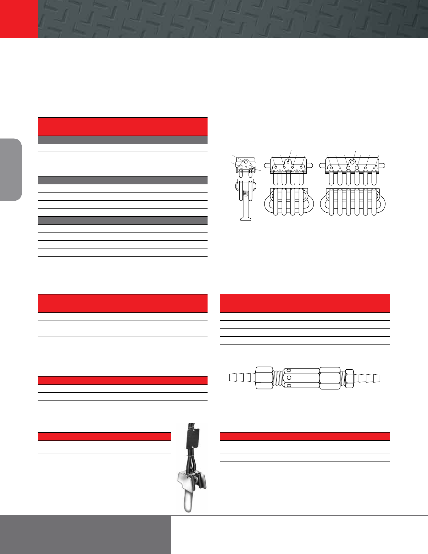
Hoist accessories for MLK and HLK Series
Metal Container
7703
Fabric Container
Chain Container
Chain Capacity* Metal Container Fabric Container
Series Part Number Part Number
MLK 13 ML10-K749 N/A
MLK 17 N/A ML50K-K749-17
MLK 26 ML20-K749A N/A
MLK 40 ML20-K749-20 N/A
MLK 45 N/A ML50K-K749-45
MLK 80 MLK-K750-80 N/A
HLK 20 HLK-K750-20 HLK-K749-20
HLK 40 HLK-K750-40 HLK-K749-40
HLK 85 HLK-K750-80 N/A
* Chain containers are for one-part single lines. For two-part lines, divide capacity by two;
for three-part lines by three, etc.
Hooks
Capacity Bullard-Burnham Bronze Latch Type*
metric Top Or Bottom Top Or Bottom
Series tons Part Number Part Number
MLK 0.25 CE110-KBB377 MLK-KRS304
MLK 0.50 CE110-KBB377 ML500KR-K377
MLK 1 CE120-KBB377 N/A
HLK 1 HLK-ABB377 HLK-SR377
HLK 1.50 HLK-ABB377 HL1500K-SR377
HLK 2 HL2000K-ABB377 HL2000K-SR377
HLK 3 HL3000K-ABB377 HL3000K-SR377
HLK 4.50 HL4500K-ABB377 HL4500K-SR377
HLK 6 HL6000K-ABB377 HL6000K-SR377
Bullard-Burnham hooks are not available for spark-resistant models.
*Not pictured.
Bullard-Burnham
hook
Manual Brake Release Kit (M)
For all MLK Series and HLK Series hoists. Part number MLK-K390.
2”
Part Number MHLK-KEXH
This two-piece kit replaces swivel air inlet on hoist. Noise is reduced with addition
of piped-away exhaust hose. Use 1” diameter exhaust hose to minimize reduction in
li speed.
Piped-away Exhaust Kits for
MLK Series and HLK Series Hoists
3/4” NPT Exhaust Port Air Supply
Hose Trolleys
Part Flange Width
Number in
7703 2.33 to 5
D10-8888 5 to 8.75
Maximum hanging weight per unit is 35 lb; each can be adjusted to fit 1/2” to 1-1/4”
O.D. hoses.
14
Air Chain
Hoists
866-207-6923
Hoist accessories for MLK and HLK Series
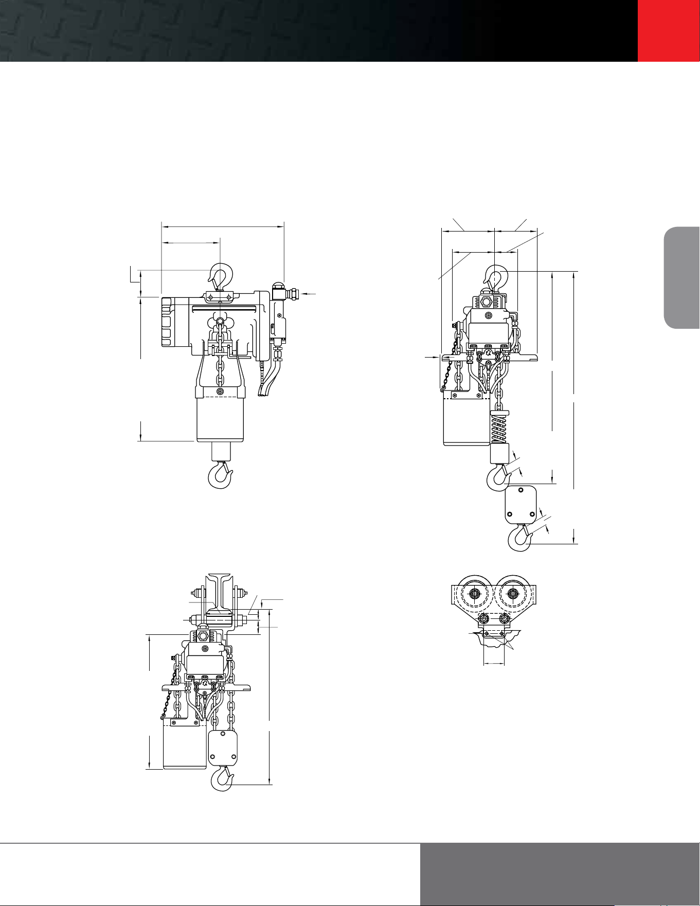
Pendent Handles
NPT Air Inlet
A B C D
Type / Part Number in in in in
SINGLE-MOTOR
MLK-A269C 1/8 1/8 N/A N/A
EZG-A269 3/8 1/8 N/A N/A
MR-269C 3/8 3/8 N/A N/A
C6H20A-A169B 1/2 1/2 N/A N/A
TWO-MOTOR
PILOT-A122B 3/8 1/8 1/8 N/A
MLK-K122B 3/8 1/8 3/8 N/A
MR-A122C 3/8 3/8 3/8 N/A
C6H20A-A122B 1/2 1/2 3/8 N/A
THREE-MOTOR
PILOT-A132B 3/8 1/8 1/8 1/8
MLK-K132B 3/8 1/8 3/8 3/8
MR-A132C 3/8 3/8 3/8 3/8
C6H20A-A132B 1/2 1/2 3/8 3/8
When a pendent-controlled hoist is purchased with a pendent-controlled power trolley or
tractor, the required two- or three-motor pendent is furnished at no extra cost in place of an
individual pendent, when specified.
Pull Chain Conversion
Part Number Description
MLK-K415A Wooden directional and crossbar handles only
CA110-B240 Standard chain; specify total length of both chains
DO2-1413 Aluminum spark-resistant chain; specify total length of both chains
Pendent Conversion Kit
Part Number Description
MLK-AL269C MLK Series, HLK Series, and HLKR Series hoists;
specify length
Quick Exhaust Valves
Pendent
Part For Use Control Length Quantity
Number With Type Style Recommended*
20417 All MLK Series Pilot Push-on 21 – 50 2
20417 HLK Series hoists 1/4” NPT hose 51 – 75 4
MR-939-6 TIR Series trolleys Full-flow Push-on 21 – 50 2
MR-939-6 MTK Series tractors 3/8” NPT hose 51 – 75 4
*The first pair of full-flow valves will be installed between 5’ and 7’ from the pendent
handle. Any additional valves will equally divide the remaining hose length.
Part number 20417. Part number MR-939-6 not shown.
B
A NPT supply
B
C B B C
A NPT supply
C CB B DD
A NPT supply
Single motor Two motor Three motor
Drawbar Hitch Kits for Use with MTK Series Tractors
Series Part Number
HL1000K, HL1500K, HL2000K No kit required; standard drawbar kit included
and HL3000K with rigid trolley with MTK Series tractors fits these hoists
MLK with rigid trolley MR-K1
Link Load Chain
Bulk Chain Size
Part Diameter / Pitch
Series Type Number mm
MLK Zinc-plated* M745Z 6.4 x 19.5
MLK Stainless steel** M745S 6.4 x 19.5
HLK Zinc-plated* H745Z 9.5 x 25.7
HLK Stainless steel** H745S 9.5 x 25.7
*Standard.
**For spark-resistant models only.
Footer 15
15
Air Chain
Hoists
ingersollrandproducts.com/liing
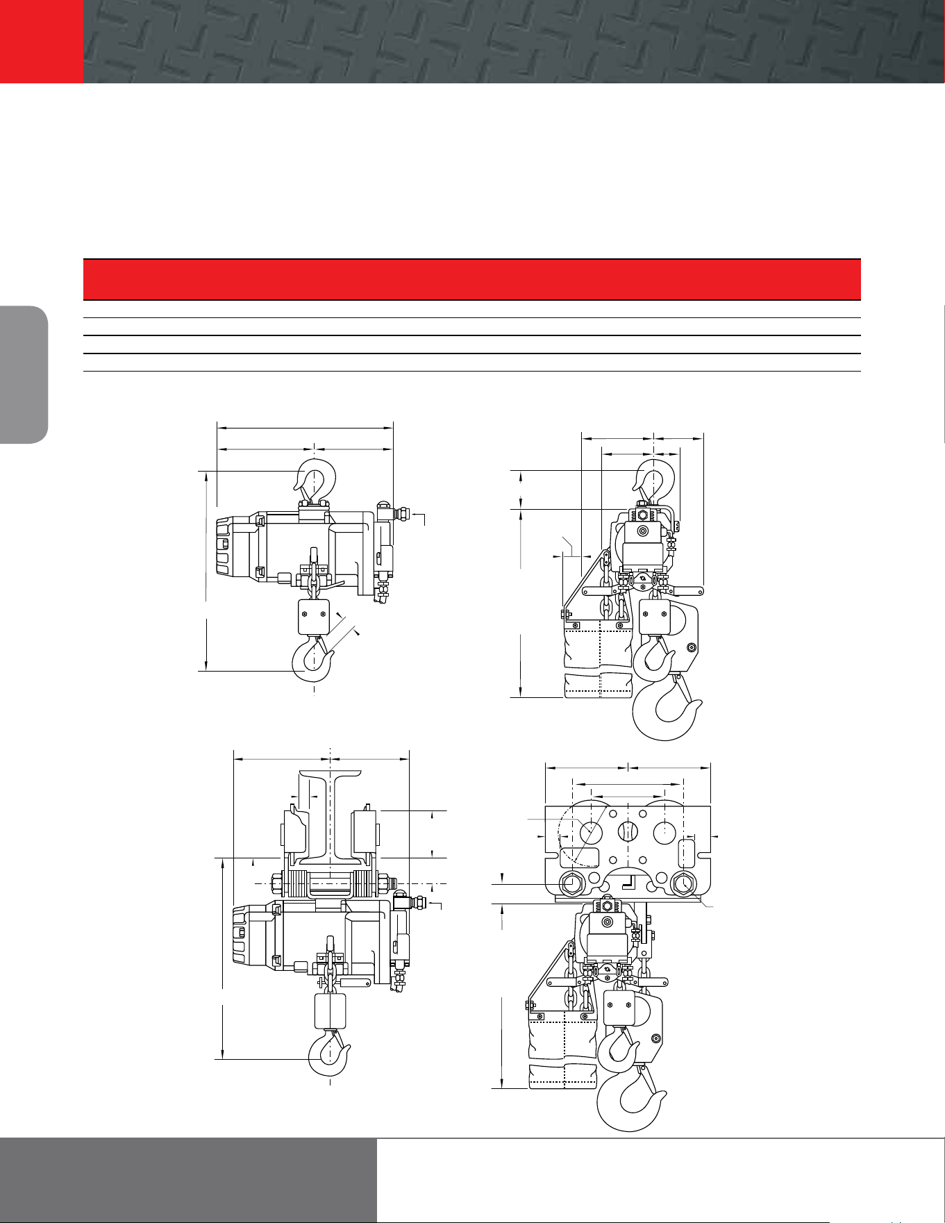
Dimensions
MLK, MLKS and MLKR Series
0.25 to 1 metric ton liing capacities
*Chain container capacities are for one-part single lines. For two-part lines, divide capacity by two.
C
L
C
L
C
L
1/4 & 1/2 t – 3-1/2”
1t – 4-1/2”
Spark-resistant
1/4 t – 3-1/2”
1/2 t – 4-1/2”
yoke pin
Chain container* fabric
17 capacity 15-1/2”
45 capacity 21-1/2”
Chain container* metal
26 capacity 18”
40 capacity 24”
13-1/2”
6-3/8”
1/2” NPT
Swivel air inlet
1/4 & 1/2 t – 5-3/4”
1t – 6-1/2”
Spark-resistant
1/4 t – 5-3/4”
1/2 t – 6-1/2”
1/4 & 1/2 t – 4-1/2”
1t – 5-5/16”
Spark-resistant
1/4 t – 4-1/2”
1/2 t – 5-5/16”
Chain container
3/4” fabric
2” metal
1/4 & 1/2 t – 4”
1t – 3-1/4”
Spark-resistant
1/4 t – 4”
1/2 t – 3-1/4”
1/4 & 1/2 t – 2”
1t – 1”
Spark-resistant
1/4 t – 2”
1/2 t – 1”
1/4 & 1/2 t – 15/16”
Spark-resistant
1-1/8” – 1/4 t
1-3/32” – 1 t
Spark-resistant
1-1/8” – 1/2 t
18”
18”
C
L
C
L
C
L
1/4 & 1/2 t – 3-9/16”
4-3/16” – 1 t
Spark-resistant
3-9/16” – 1/4 t
4-3/16” – 1/2 t
Chain container*: fabric
17 capacity 15-1/2”
45 capacity 21-1/2”
Chain container*: metal
26 capacity 18”
40 capacity 24”
1/4 & 1/2 t – 1-1/2”
1-5/8” – 1 t
Spark-resistant
1-1/2”
Bottom of
wheel
1/4 & 1/2 t – 1-1/8”
2-1/2” – 1 t
Spark-resistant
1-1/8” – 1/4 t
2-1/2” – 1/2 t
yoke pin
18”
C
L
C
L
C
L
yoke pin
41/64”
dia. hole in lug mount
3”
16
Air Chain
Hoists
866-207-6923
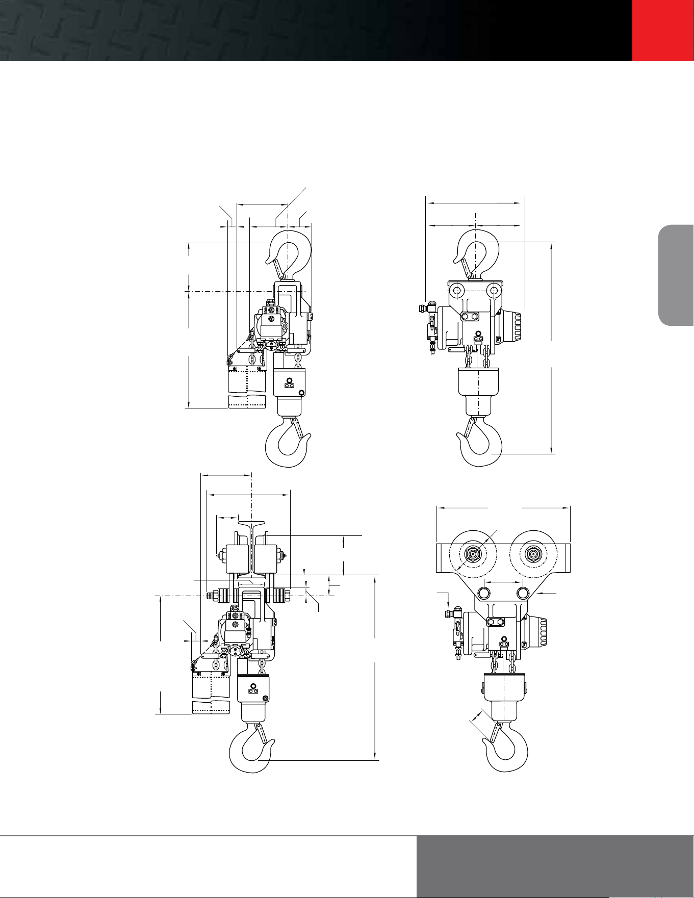
HLK and HLKR Series
1 to 3 metric ton liing capacities
Dimensions
Min
A B C D E F G H K
Series in in in in in in in in in
HL1000K/R 18.5 4.8 7.3 2.4 5.4 3.5 4.5 2.4 18.1
HL1500K 18.5 4.8 7.3 2.4 5.4 3.5 4.5 2.4 18.9
HL2000K 23 3.6 8.4 2.4 6.6 5.8 4.5 2.4 21.6
HL3000K 23 3.6 8.4 2.4 6.6 6.3 4.5 2.4 22.6
*Chain container capacities are for one-part single lines (1- and 1.50-ton). For two-part lines, divide capacity by two.
16-1/4”
8-13/16” 7-7/16”
1/2” NPT
swivel air inlet
HL1000K and HL1500K
1-3/16”
HL1000KR spark-resistant
1-11/32”
HL2000K
1-3/8”
HL3000K
1-11/16”
A
Chain container*
20 capacity
22-3/8”
40 capacity
30-3/8”
F
C B
E D
2-1/2”
8-13/16” 7-7/16”
1-5/32”
Bottom
of
wheel
1/2” NPT
swivel air inlet
G
Tread dia.
H
K
7-3/8” 7-3/8”
5-3/4”
1-17/64”
1-7/8”
10.24”
6.68”
1-1/2”
1” Bolt
Chain container*
20 capacity
22-3/8”
40 capacity
30-3/8”
Footer 17
17
Air Chain
Hoists
ingersollrandproducts.com/liing
HLK Series
4.50 to 6 metric ton liing capacities
*Chain container capacities are for single-line. For three-part 4.50-ton units, divide capacity by three. For four-part 6-ton units, divide capacity by four.
**For additional geared and motorized trolley dimensions refer to dimensions in the TIR Series trolley section.
2-1/2”
4-1/2 t – 9-7/8”
6 t – 9-1/4”
4-1/2 t – 8”
6 t –7-3/8”
4-1/2 t – 3-3/4”
6 t – 4-3/8”
4-1/2 t – 6-1/2”
6 t – 7-3/4”
Chain container*
40 capacity
33-7/16”
16-1/4”
4-1/2 t – 8-5/8”
6 t – 9”
4 -1/2 t – 7-13/16”
6 t – 7-1/4”
4-1/2 t – 30-7/8”
6 t – 36-3/16”
4-1/2 t – 9-7/8”
6 t – 9-1/4”
14-3/4”
4-9/16”
4-7/8” lug width
7” tread dia.
Bottom
of wheel
3-5/8”
1-5/8”
4-1/2 t – 28”
6 t – 32-3/16”
Chain container*
40 capacity
33-7/16”
80 capacity
51-7/16”
1/2” NPT
swivel air inlet
**19-3/8”
8-5/8” wheel diameter
1-1/8”
bolt diameter
4-1/2 t – 1-11/16”
6 t – 2-1/16”
7”
Dimensions

18
Air Chain
Hoists
866-207-6923
Example: ML500KR-2R10R6U
M L 500K R - 2 R 10 - R 6 U
Series
M = Series
H = Series
Suspension
A = Fixed lug
B = Bullard hook (self closing)
R = Bronze snap hook
C = Swivel top hook
CP = Copper-plated top hook
DA
(3)
= Plain rigid trolley
(universal wheels “A” flange)
DD
(3)
= Plain rigid trolley
(universal wheels “D” flange)
FXXA
(2)(3)
= Hand geared trolley
(universal wheels “A” flange)
FXXD
(2)(3)
= Hand geared trolley
(universal wheels “D” flange)
HA
(3)
= Vane mtr. powered trolley
(universal wheels “A” flange)
HD
(3)
= Vane mtr. powered trolley
(universal wheels “D” flange)
Capacity
250K = 250 kg = 550 lb
500K = 500 kg = 1,100 lb
1000K = 1,000 kg = 2,200 lb
1500K = 1,500 kg = 3,300 lb
2000K = 2,000 kg = 4,400 lb
3000K = 3,000 kg = 6,600 lb
4500K = 4,500 kg = 10,000 lb
6000K = 6,000 kg = 13,200 lb
Lower hook
C = Steel snap hook
CP = Copper-plated lower hook
R = Bronze snap hook
B = Bullard self-closing hook
HOW TO ORDER
Specify hoist by complete model number code as illustrated below. If a trolley is required, specify beam size, type and flange width.
Specify accessories separately by part number. Note that 0 is a number, not a letter, in model part numbers.
Link chain
type
Spark-resistant
R = Add for spark-resistant
(0.25, 0.50 t MLKR and 1
t HLKR)
S = Add for slow speed spotting
(0.25, 0.50, 1 t MLKS)
Control
0 = No controls
1 = Pull chain
2 = Pendent
3 = 2 Motor
pendent
(1)
4 = 3 Motor
pendent
(1)
Li ()
10 = 10
(standard)
XX = Specify
length
Length of pull/chain or
pendent control hose ()
6 = 10 (standard)
XX = Specify length
NOTE:
(1) Required with “H” suspension.
(2) XX = specify hand chain length if other than standard
“08” (8 ) required.
(3) For solid bronze wheels on non-spark resistant models,
add “R” to the end of the trolley suspension code. (See
pages 20 and 21 for price.)
Options
CR = Copper-plated bottom block
M = Manual brake release kit
P = Piped away exhaust
S = Steel chain container
U = Fabric chain container
MLK and HLK Series
0.25 to 6 metric ton liing capacities
Footer 19
19
Air Chain
Hoists
ingersollrandproducts.com/liing
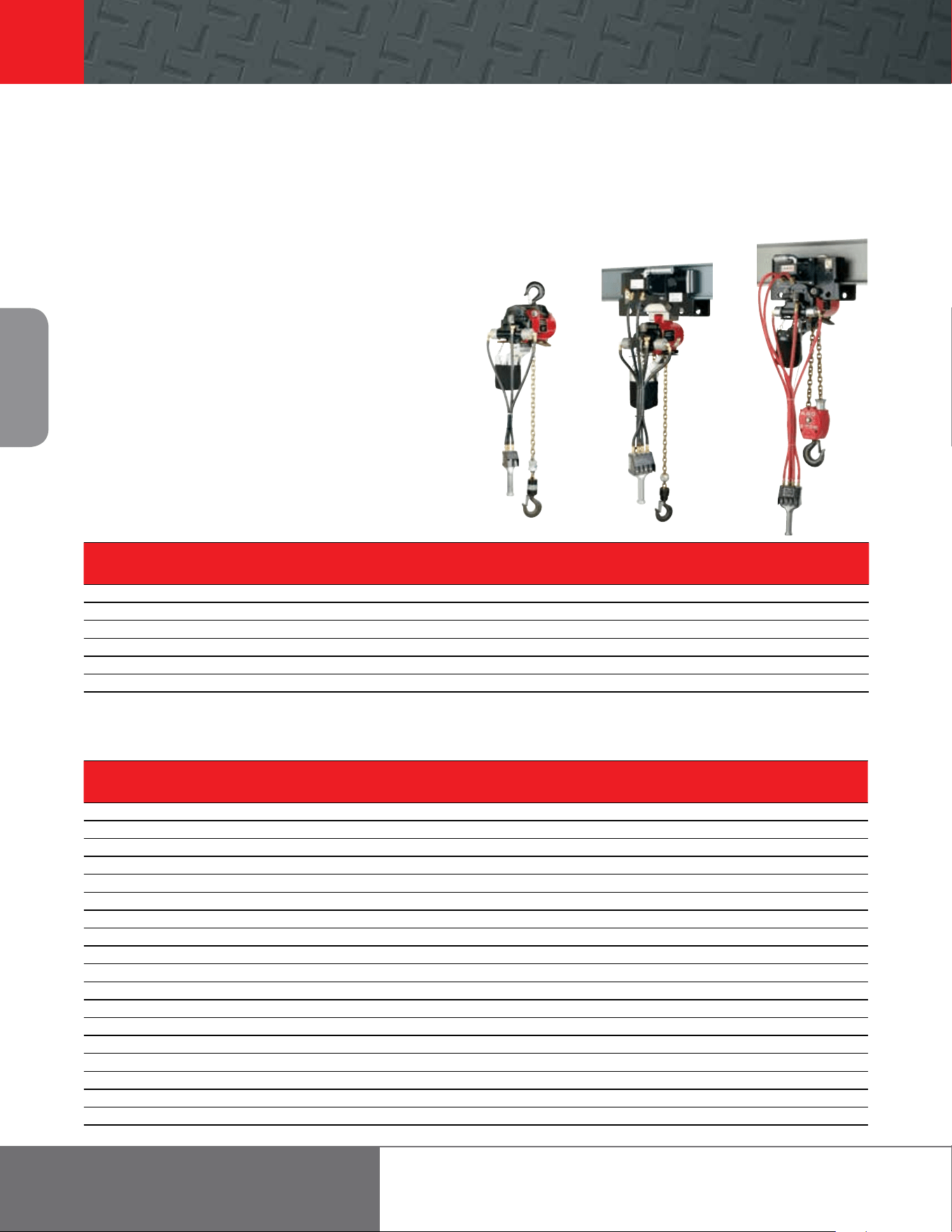
7700 Series and 7790 Series link chain hoists
Air motor and gearing
Provides faster li speeds
with low air consumption.
Durable construction
Cast housing with
heavy-gauge brake cap
protects working parts.
Quiet operation
Dual internal muer pads
reduce exhaust noise.
Piped-away exhaust kits
are available.
Brake adjustment
Brake is easily adjusted to
meet specific load ranges.
Li / descent adjustment
Operating speeds can be safely
set to match desired rates.
Compact and lightweight
Sized for easy installation,
even in small, confined areas.
Pendent and pull-chain
control puts complete
control in the operator’s hand.
Quality and performance
Ingersoll Rand hoists can be equipped with
a variety of optional features that can be matched
to the specifications of almost any job. Their long
operating life, cost-eective service and
maintenance, and dependable performance are
supported by a host of standard features.
Rotary-vane air motors
These powerful, self-cooling rotary motors keep
Ingersoll Rand hoists at peak performance in
high-temperature situations. And, because they
are air-powered, they further reduce the chance
of causing sparks in a volatile environment.
Complete operator control
A pressure pendent or pull chain puts complete
control of the hoist in the operator’s hand. These
hoists respond immediately to an operator’s
“inching” commands.
External brake adjustment
Easily customizes the sensitivity of the hoist to
the load range for any application. This results in
ease of operation with better spotting, feathering,
and overall control.
Fast, ecient load handling
Rotary-vane air motors and ecient gearing
combine to deliver one of the fastest li speeds
available. Gear ratios have been calculated to
yield the lowest possible air consumption.
Job-matched performance
Numerous options allow Ingersoll Rand hoists to be
matched to specific application requirements,
including link or roller load chains, hook types,
manual and power trolleys, pull chain or pendent
control, standard and spark-resistant, and 300-lb to
2-ton capacities.
Clean and quiet
For applications and environments that require
clean air, exhaust can be piped away. A two-stage
filtration system removes foreign matter from air
supplies so motors can operate at peak performance
with longer operating lives.
Easy installation
Lightweight and convenient, Ingersoll Rand hoists
are easier to install than any other model. Even in
small, confined areas, they can be installed and
removed with minimal eort.
20
Air Chain
Hoists
866-207-6923
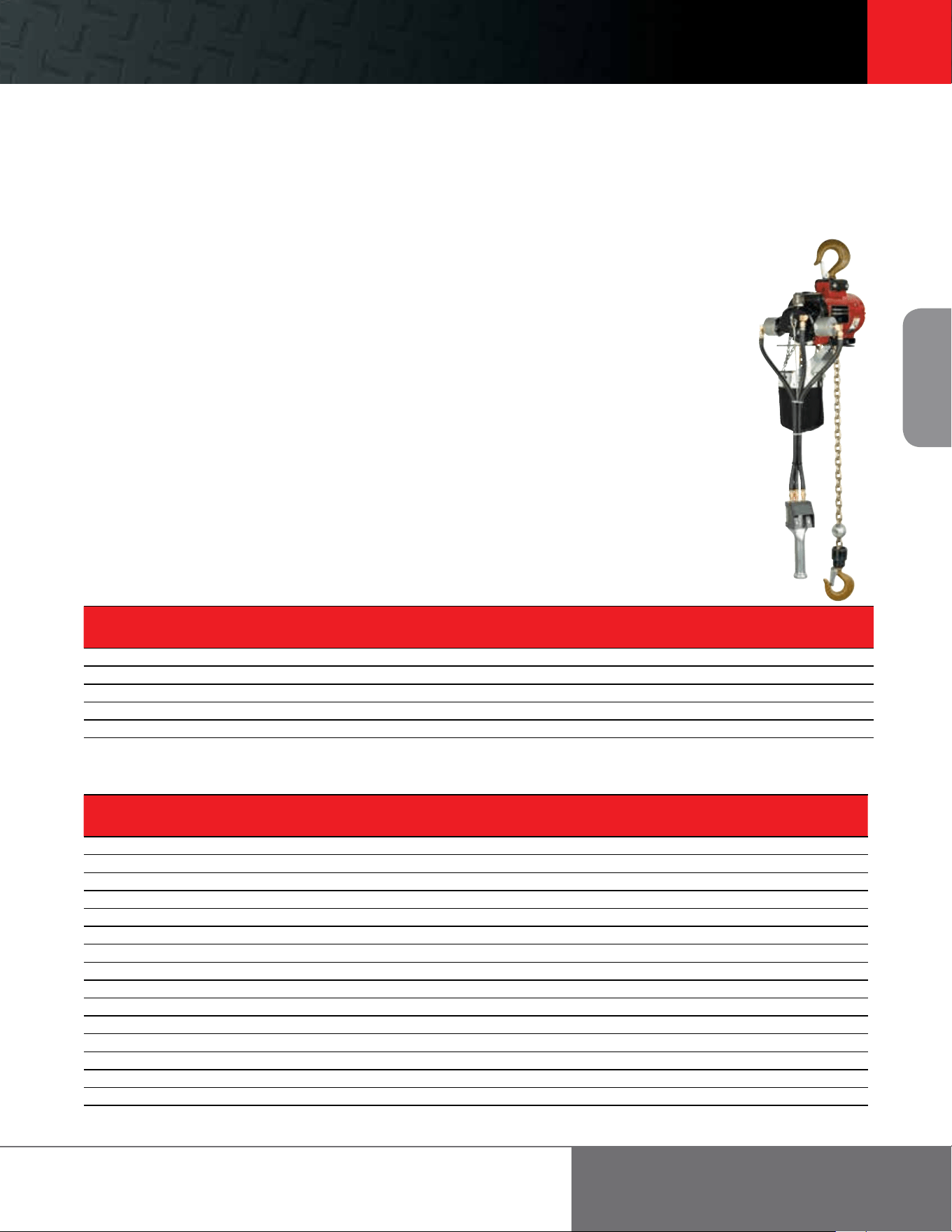
Continuous heavy-duty applications
The 7700 and 7790 Series has been designed specifically for heavy-duty
industrial applications where loads vary between 275 and 4,400 lb. Simple,
rugged, and reliable, these hoists are constructed with few moving parts for
easy repair and less downtime. These hoists come complete with 10 feet of
standard li and 6 feet of either pendent control or pull-chain control.
Features
• Exceptional slow-speed control provides superior “spotting” characteristics
• Powerful, self-cooling rotary motors keep hoists at peak performance in
high temperatures
• Brake control easily adjusts to meet specific load ranges
• Motor and gearing provide faster li speeds with low air consumption
7700 Series and 7790 Series link chain hoists
0.125 to 2 metric ton liing capacities
7700 Series and 7790 Series Specifications
Model
Capacity
# Falls
Hook Mount
Headroom
Trolley Mount
Headroom
Liing Speed Lowering Speed
Chain
Size
Chain Weight
(per foot of li)
Net Weight
w/10 of Li
metric
tons
Rated Load No Load Rated Load No Load
lb in mm in mm /min m/min /min m/min /min m/min /min m/min lb kg lb kg
7770E 275 0.125 1 17 431.8 16.9 429.3 110 33.5 192 58.5 275 83.8 159 48.5 0.25 x 0.75 0.6 0.3 41 18.6
7718E 550 0.25 1 17 431.8 16.9 429.3 82 25 184 56.1 224 68.3 153 46.6 0.25 x 0.75 0.6 0.3 41 18.6
7756E 1,100 0.50 1 17 431.8 16.9 429.3 41 12.5 72 22 112 34.1 60 18.3 0.25 x 0.75 0.6 0.3 41 18.6
7776E 2,200 1 2 21.7 551.2 20.5 520.7 21 6.4 36 11 56 17.1 30 9.1 0.25 x 0.75 1.7 0.5 53 24
7790A 2,200 1 1 18.9 480.1 15 381 26 7.9 37 11.3 44 13.4 31 9.5 0.312 x 0.858 0.9 0.4 62 28.1
7792A 4,400 2 2 22.4 569 18 457.2 12 3.7 20 6.1 24 7.3 17 5.2 0.312 x 0.858 1.8 0.8 81 36.7
Working pressure from 5 to 7 bar (70 to 100 psi). Air consumption @ rated load - all models 1.98 m (70 cfm). Air inlet 1/2” NPT. Sound level 85 dBA.
Trolley Mount Specifications
Model
Trolley
type
Capacity
metric tons
Minimum
Headroom
Trolley Speed at
Rated Load
Air Consumption @
Rated Load
Trolley Flange
Adjustment
Minimum Curve
Radius Air Inlet
Net Weight
w/10 of Li
in mm /min m/min
3
/min m
3
/min in mm m lb kg
7770E Plain 0.125 17 432 - - - - 2.66-12 68-305 3.5 1.1 - 88 40
Geared 0.125 17 432 - - - - 2.66-12 68-305 3.5 1.1 - 91 41
Motor 0.125 17 432 96 30 35 1 2.66-12 68-305 3.5 1.1 1/4 94 13
7718E Plain 0.25 17 432 - - - - 2.66-12 68-305 3.5 1.1 - 88 40
Geared 0.25 17 432 - - - - 2.66-12 68-305 3.5 1.1 - 91 41
Motor 0.25 17 432 95 29 35 1 2.66-12 68-305 3.5 1.1 1/4 94 43
7756E Plain 0.50 17 432 - - - - 2.66-12 68-305 3.5 1.1 - 88 40
Geared 0.50 17 432 - - - - 2.66-12 68-305 3.5 1.1 - 91 41
Motor 0.50 17 432 95 29 35 1 2.66-12 68-305 3.5 1.1 1/4 94 43
7776E Plain 1 22 559 - - - - 3.25-12 82-305 3.5 1.1 - 100 45
Geared 1 22 559 - - - - 3.25-12 82-305 3.5 1.1 - 103 47
Motor 1 22 559 93 28 35 1 3.25-12 82-305 3.5 1.1 1/4 106 48
7790A Plain 1 15 381 - - - - 3.00-12 76-305 3.5 1.1 - 104 47
Geared 1 15 381 - - - - 3.00-12 76-305 3.5 1.1 - 107 49
Motor 1 15 381 93 28 35 1 3.00-12 76-305 3.5 1.1 1/4 110 50
7792A Plain 2 20 508 - - - - 3.00-12 76-305 3.5 1.1 - 123 56
Geared 2 20 508 - - - - 3.00-12 76-305 3.5 1.1 - 126 57
Motor 2 20 508 80 24 35 1 3.00-12 76-305 3.5 1.1 1/4 129 59
Working pressure from 5 to 7 bar (70 to 100 psi).
Footer 21
21
Air Chain
Hoists
ingersollrandproducts.com/liing
7700 Series and 7790 Series Specifications
Model
Capacity
# Falls
Hook Mount
Headroom
Trolley Mount
Headroom
Liing Speed Lowering Speed
Chain
Size
Chain Weight
(per foot of li)
Net Weight
w/10 of Li
metric
tons
Rated Load No Load Rated Load No Load
lb in mm in mm /min m/min /min m/min /min m/min /min m/min lb kg lb kg
7770E 275 0.125 1 17 431.8 16.9 429.3 110 33.5 192 58.5 275 83.8 159 48.5 0.25 x 0.75 0.6 0.3 41 18.6
7718E 550 0.25 1 17 431.8 16.9 429.3 82 25 184 56.1 224 68.3 153 46.6 0.25 x 0.75 0.6 0.3 41 18.6
7756E 1,100 0.50 1 17 431.8 16.9 429.3 41 12.5 72 22 112 34.1 60 18.3 0.25 x 0.75 0.6 0.3 41 18.6
7776E 2,200 1 2 21.7 551.2 20.5 520.7 21 6.4 36 11 56 17.1 30 9.1 0.25 x 0.75 1.7 0.5 53 24
7790A 2,200 1 1 18.9 480.1 15 381 26 7.9 37 11.3 44 13.4 31 9.5 0.312 x 0.858 0.9 0.4 62 28.1
7792A 4,400 2 2 22.4 569 18 457.2 12 3.7 20 6.1 24 7.3 17 5.2 0.312 x 0.858 1.8 0.8 81 36.7
Working pressure from 5 to 7 bar (70 to 100 psi). Air consumption @ rated load - all models 1.98 m (70 cfm). Air inlet 1/2” NPT. Sound level 85 dBA.
Trolley Mount Specifications
Model
Trolley
type
Capacity
metric tons
Minimum
Headroom
Trolley Speed at
Rated Load
Air Consumption @
Rated Load
Trolley Flange
Adjustment
Minimum Curve
Radius Air Inlet
Net Weight
w/10 of Li
in mm /min m/min
3
/min m
3
/min in mm m lb kg
7770E Plain 0.125 17 432 - - - - 2.66-12 68-305 3.5 1.1 - 88 40
Geared 0.125 17 432 - - - - 2.66-12 68-305 3.5 1.1 - 91 41
Motor 0.125 17 432 96 30 35 1 2.66-12 68-305 3.5 1.1 1/4 94 13
7718E Plain 0.25 17 432 - - - - 2.66-12 68-305 3.5 1.1 - 88 40
Geared 0.25 17 432 - - - - 2.66-12 68-305 3.5 1.1 - 91 41
Motor 0.25 17 432 95 29 35 1 2.66-12 68-305 3.5 1.1 1/4 94 43
7756E Plain 0.50 17 432 - - - - 2.66-12 68-305 3.5 1.1 - 88 40
Geared 0.50 17 432 - - - - 2.66-12 68-305 3.5 1.1 - 91 41
Motor 0.50 17 432 95 29 35 1 2.66-12 68-305 3.5 1.1 1/4 94 43
7776E Plain 1 22 559 - - - - 3.25-12 82-305 3.5 1.1 - 100 45
Geared 1 22 559 - - - - 3.25-12 82-305 3.5 1.1 - 103 47
Motor 1 22 559 93 28 35 1 3.25-12 82-305 3.5 1.1 1/4 106 48
7790A Plain 1 15 381 - - - - 3.00-12 76-305 3.5 1.1
- 104 47
Geared 1 15 381 - - - - 3.00-12 76-305 3.5 1.1 - 107 49
Motor 1 15 381 93 28 35 1 3.00-12 76-305 3.5 1.1 1/4 110 50
7792A Plain 2 20 508 - - - - 3.00-12 76-305 3.5 1.1 - 123 56
Geared 2 20 508 - - - - 3.00-12 76-305 3.5 1.1 - 126 57
Motor 2 20 508 80 24 35 1 3.00-12 76-305 3.5 1.1 1/4 129 59
Working pressure from 5 to 7 bar (70 to 100 psi).
Continuous heavy-duty applications
7700 Series — 500 to 1,500 lb capacities
7790 Series — 1,500 to 3,000 lb capacities
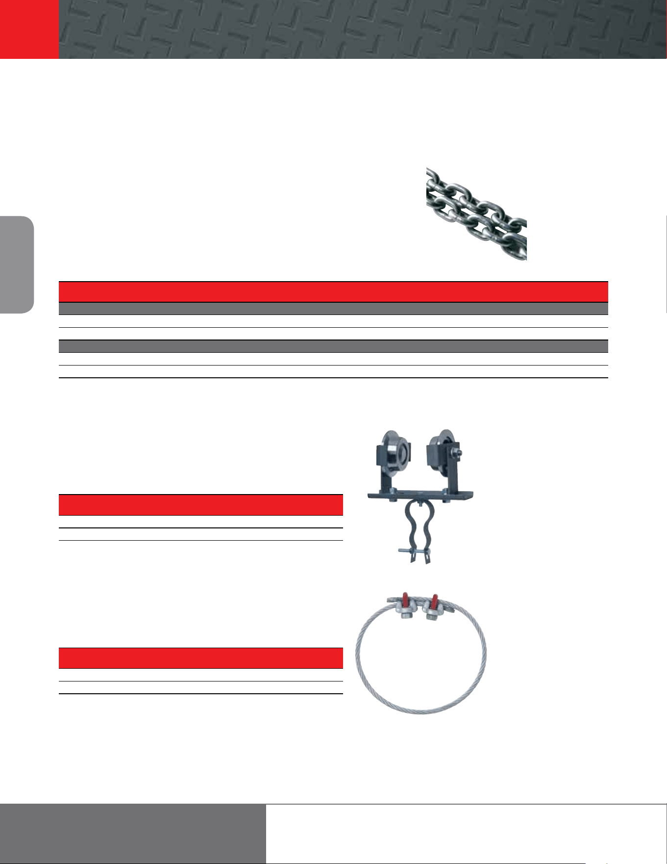
7700 Series and 7790 Series spark-resistant hoists are designed for Division 1
applications where, under normal operating conditions, the atmosphere contains
hazardous concentrations of flammable gases, dust, or other materials.
Specifically engineered for continuous heavy-duty industrial applications —
between 500 and 3,000 lb — Ingersoll Rand 7700 Series and 7790 Series
spark-resistant hoists are available with bronze top-hook or trolley adapter
suspension. These hoists come complete with 10 feet of standard li and 6 feet
of either pendent control or pull-chain control.
Features
• Stainless steel load chain and solid bronze hooks prevent accidental sparking
• Pendent control handles, when ordered, are covered with an industrial-grade
vinyl grip; pull-chain controls come standard with zinc-plated pull chain
• Hoist capacities are reduced and speed adjustments are locked into place to
maximize chain life
• Trolley models are supplied with bronze wheels
Division 1 and 2 applications
The following definitions may be used as
a guide. The actual division distinction for
each application must be determined by
your local inspecting authority.
Division 1 (spark-resistant air hoists are
required)
Atmospheres containing hazardous
concentrations of flammable gases, dusts,
or fibers; continuously, frequently, or
periodically; under normal operating
conditions.
Division 2 (standard air hoists are
required)
Normally non-hazardous atmospheres
in which a hazardous concentration of
flammable gases, dusts, or fibers occurs
when a container or handling system fails or
the ventilating system that normally keeps
the concentration non-hazardous fails.
7700 Series and 7790 Series link chain hoists
Spark-resistant models
7700 Series and 7790 Series Spark-resistant Specifications
Model
Capacity
# Falls
Hook Mount
Headroom
Trolley Mount
Headroom
Liing Speed Lowering Speed
Chain
Size
Chain Weight
(per foot of li)
Net Weight
w/10 of Li
metric
tons
Rated Load No Load Rated Load No Load
lb in mm in mm /min m/min /min m/min /min m/min /min m/min lb kg lb kg
7712EL 550 0.25 1 17 431.8 17.1 434.3 50 15.2 80 24.4 70 21.3 53 16.2 0.25 x 0.75 0.6 0.3 41 18.6
7714EL 1,500 0.68 2 22.7 576.6 21.3 541 16 4.9 26 7.6 16 4.9 12 3.7 0.25 x 0.75 1.2 0.6 48 21.8
7796AL 1,500 0.68 1 18.9 480.1 15 381 16 4.9 26 7.6 16 4.9 12 3.7 0.312 x 0.858 0.9 0.4 62 28.1
7798AL 2,400 1.1 2 22.4 569 18 457.2 12 3.7 19 5.8 12 3.7 9 2.7 0.312 x 0.858 1.9 0.9 81 36.7
7799AL 3,000 1.36 2 22.4 569 18 457.2 7 2.1 11 3.4 7 2.1 5 1.5 0.312 x 0.858 1.9 0.9 81 36.7
Working pressure from 5 to 7 bar (70 to 100 psi). Air consumption @ rated load - all models 1.98 m (70 cfm). Air inlet 1/2” NPT. Sound level 85 dBA.
Trolley Mount Specifications
Model
Trolley
type
Capacity
metric tons
Minimum
Headroom
Trolley Speed at
Rated Load
Air Consumption @
Rated Load
Trolley Flange
Adjustment
Minimum Curve
Radius
Net Weight
w/10 of Li
in mm /min m/min
3
/min m
3
/min in mm m Air Inlet lb kg
7712-EL Plain 0.25 17 432 - - - - 2.66-12 68-305 3.5 1.1 - 88 40
Geared 0.25 17 432 - - - - 2.66-12 68-305 3.5 1.1 - 91 41
Motor 0.25 17 432 96 30 35 1 2.66-12 68-305 3.5 1.1 1/4 94 43
7714EL Plain 0.68 22 559 - - - - 3.25-12 82-305 3.5 1.1 - 95 43
Geared 0.68 22 559 - - - - 3.25-12 82-305 3.5 1.1 - 98 45
Motor 0.68 22 559 93 28 35 1 3.25-12 82-305 3.5 1.1 1/4 101 46
7796AL Plain 0.68 15 381 - - - - 3.00-12 76-305 3.5 1.1 - 104 47
Geared 0.68 15 381 - - - - 3.00-12 76-305 3.5 1.1 - 107 49
Motor 0.68 15 381 93 28 35 1 3.00-12 76-305 3.5 1.1 1/4 110 50
7798AL Plain 1.1 20 508 - - - - 3.00-12 76-305 3.5 1.1 - 123 56
Geared 1.1 20 508 - - - - 3.00-12 76-305 3.5 1.1 - 126 57
Motor 1.1 20 508 93 28 35 1 3.00-12 76-305 3.5 1.1 1/4 129 59
7799AL Plain 1.4 20 508 - - - - 3.00-12 76-305 3.5 1.1 - 123 56
Geared 1.4 20 508 - - - - 3.00-12 76-305 3.5 1.1 - 126 57
Motor 1.4 20 508 84 25 35 1 3.00-12 76-305 3.5 1.1 1/4 129 59
Working pressure from 5 to 7 bar (70 to 100 psi).
22
Air Chain
Hoists
866-207-6923
Hoist accessories for 7700 and 7790 Series
Hoist Capacity Chain Part Chain Size Weight Feet in
Used On lb No. Dia./Pitch lb/ Package
ZINC PLATED LINK
7700 Series 275, 550, 1,100, 2,200 37708 .25 / .75 .6 250
7790 Series 2,200 & 4,400 42988 .312 / .858 .9 250
STAINLESS STEEL LINK
7700 Series 500, 1,500 39489 .25 / .75 .6 250
7790 Series 1,500, 2,400, 3,000 43095 .312 / .858 .9 250
Part Max Hose O.D. Min/Max Min/Max Beam
No. in Beam Height (in) Flange Width (in)
7703 11/4 3-10 2-3/8 - 5
D10-8888 5 - 8-3/4
Hoist Part Cable Dia. Cable Length
Used On No. in
7700 Series 43231 1/4 2
7790 Series 43059 5/16 3-1/2
Load chain
Ingersoll Rand hoists are oered with several dierent load chains. Standard hoists come
complete with steel load chains. Spark-resistant hoists come with stainless-steel link load
chain.
Chain length 7700 Series (0.25-, 0.50-ton), 7790 Series (1-ton)
Length of li desired + 1 foot = load chain length
Chain length 7700 Series (1-ton), 7790 Series (2-ton)
2 x length of li desired + 2 feet = load chain length
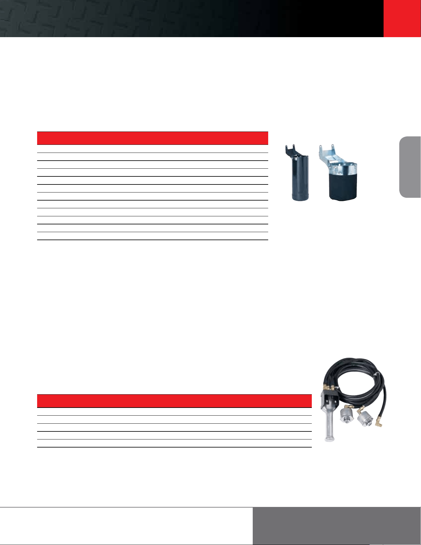
Hose Carrier Trolley
Easily tracks along same beam that hoist is mounted on. Keeps air hose
suspended and out of operator’s way. Use one for each 8 feet of hose length.
Restraining Cable
For use as an added safety precaution in hoist suspension. Cable inserts through
hole in hoist housing and around I-beam or other structure capable of safely
supporting hoist and hoist load weight. Order based upon hoist used.
7703
43231
Link chain
Footer 23
23
Air Chain
Hoists
ingersollrandproducts.com/liing
Hoist accessories for 7700 and 7790 Series
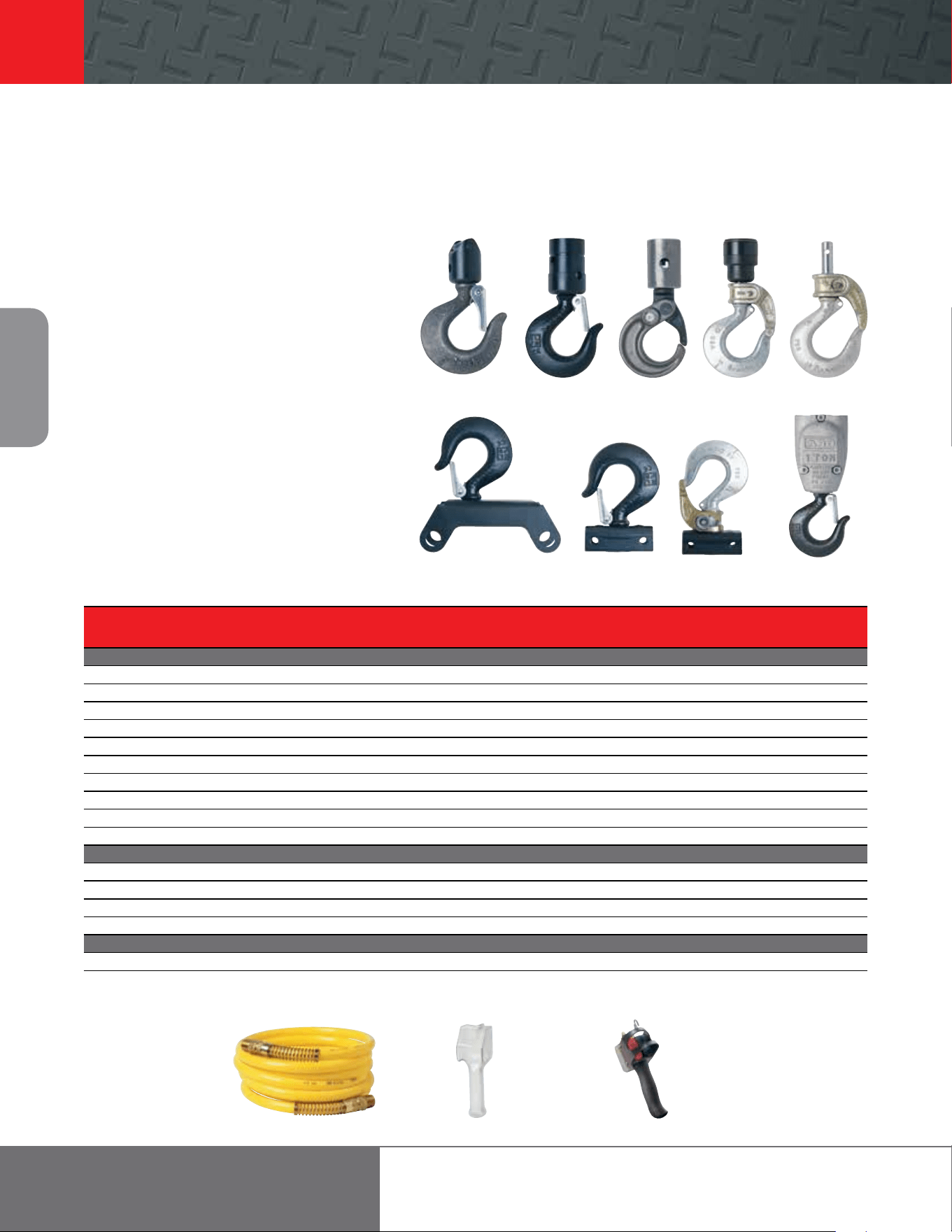
Chain Baskets
Catches and stores load chain as load is lied. Mounts directly to side of hoist. Order based upon load chain length and
hoist being used. Load chain length on 1-ton 7700 Series hoists and 2-ton 7790 Series hoists is twice the li distance.
Exhausts
Piped exhaust
1
Allows exhaust to be piped to a remote area. This is particularly desirable
for applications in food processing, chemicals, and processes where
atmospheric purity must be maintained.
How to order: specify as option in Ordering Guide.
20308-4 exhaust muer
Threads into exhaust port to minimize sound level. Can be used on 7700
and 7790 Series hoists ordered with piped exhaust option.
For field conversion
All 7700 Series hoists may be converted to a piped-away exhaust by
ordering 46098-1 Head Assembly.
All 7790 Series hoists (except power trolley models) may be converted to a
piped-away exhaust by ordering 43029 Piped Exhaust Adapter.
(1) Hose not included. Exhaust port is 1/2” NPTF.
Hoist Controls
To convert from pull chain to pendent control: Either nylon braid (standard) or steel braid control hose is available. Steel
braid hose is recommended to resist heat or abrasion. Specify the model shown, inserting the pendent length in feet for the *.
Maximum 20 feet.
To convert from pendent control to pull chain: Specify 40004-*, where the * is pull chain length desired. Also required are
two 34026 valve caps; two Y325-116 O-rings; two 38966 springs and one Y227-3 pipe plug per hoist.
Link Chain
Canvas
Basket
Link Chain
Metal
Basket
Hoist Type of Standard Length
Used On Model Control
All 7700E Series 46094-* Pendent – nylon braid hose 6
All 7700E Series 46369-* Pendent – steel braid hose 6
All 7790 Series 43106-* Pendent – nylon braid hose 6
All 7790 Series 46364-* Pendent – steel braid hose 6
All 7700 & 7790 Series 40004-* Pull chain 5
Load Chain Link Chain (metal basket) Link Chain (canvas basket
1
)
Max Lineal Feet 7700 7790 7700 7790
10 – 49800 – 10 – 43441 – 1
12 – – – –
16 37653 – 16 – – –
20 – 49800 – 20 43554 – 1 43441 – 2
30 – 49800 – 30 – –
32 37653 – 32 – 43554 – 2 –
40 – 49800 – 40 – 43554 – 3
56 37653 – 64 – – –
60 – 49800 – 60 – –
64 – – 43554 – 3 –
80 37653 – 80 49800 – 80 – –
59 37653 –100 49800 – 100 – –
(1) Canvas baskets are made of specially treated oil-resistant material.
24
Air Chain
Hoists
866-207-6923
Hoist accessories for 7700 and 7790 Series
Hooks For Link Chain Hooks For Roller Chain
Capacity Upper Hook Lower Hook Upper Hook Lower Hook
Hoist Series (lb) Hook Opening (in) Hook Opening (in) Hook Opening (in) Hook Opening (in)
STEEL SNAP HOOKS
7700 Series 0.125, 0.25 and 0.50 ton 275/550/1,100 34921 1-1/8 35014 1 34921 1-1/8 33381-1 1
7700 Series 0.25 ton spark res. 500 35113 1-1/8 46565 1 35113 1-1/8 34655-1 1
7700 Series 1 ton 2,200 34921 1-1/8 45707
1
1-1/8 34921 1-1/8 45708
1
1-1/8
7700 Series 0.50 ton spark res. 1,000 N/A – N/A – 35113 1-1/8 45710
1
1-1/8
7700 Series 0.75 ton spark res. 1,500 35113 1-1/8 45709
1
1-1/8 N/A – N/A –
7790 Series 1 ton 2,200 43002 1-1/8 43000 1-1/8 N/A – N/A –
7790 Series 0.75 ton spark res. 1,500 43097 1-1/8 43110 1 N/A – N/A –
7790 Series 2 ton 4,400 43049 1-1/4 43048
1
1-1/4 N/A – N/A –
7790 Series 1 ton spark res. 2,400 43096 1-1/4 43101 1-1/4 N/A – N/A –
7790 Series 1.50 ton spark res. 3,000 43096 1-1/4 43101 1-1/4 N/A – N/A –
BULLARD HOOKS
7700 Series 0.25 and 0.50 ton 550/1,100 35203 1-3/16 35206 1-1/16 35203 1-3/16 35205 1-1/16
7700 Series 1 ton 2,200 35203 1-3/16 45934
1
1-3/16 35203 1-3/16 45935
1
1-3/16
7790 Series 1 ton 2,200 43458 1-3/16 43456 1-3/16 N/A – N/A –
7790 Series 2 ton 4,400 43459 1-7/16 43460 1-7/16 N/A – N/A –
SELF-CLOSING LATCH HOOKS
7700 Series 0.125, 0.25 and 0.50 ton 275/550/1100 N/A – 42799 1-1/2 N/A – N/A –
(1) Includes Sheave Block
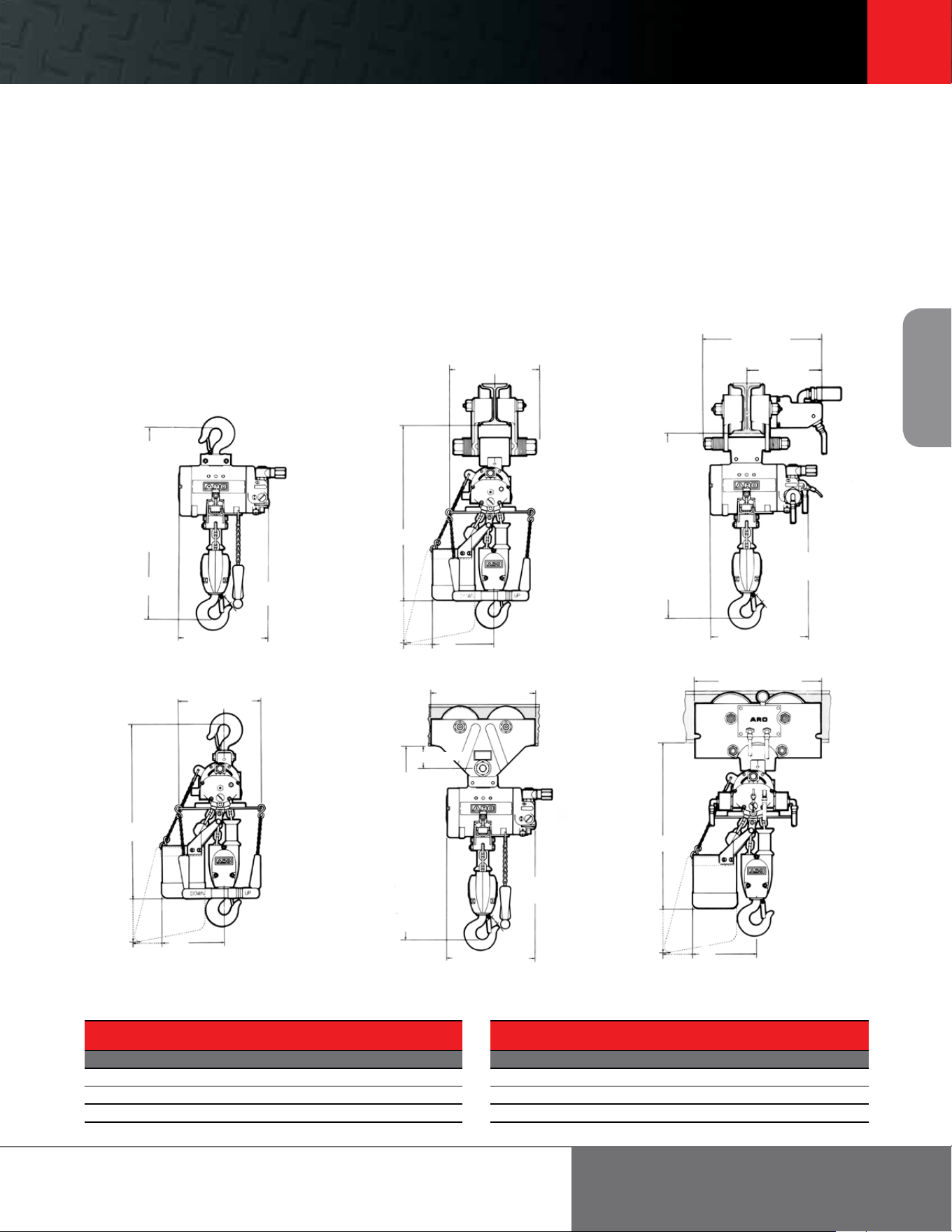
Hooks
Ingersoll Rand oers three dierent hook configurations
designed to meet the needs of any material handling
application. All hooks must be ordered separately by specifying
model required according to hoist and beam configurations.
Steel snap-hooks
Steel snap-hooks have a spring-loaded latch to prevent a liing
eye from popping out of the hook while the load is “grounded.”
This style of self-closing hooks is the most popular as they are
easy and inexpensive to replace.
Bullard hooks
Ideal for rough, high-speed, repetitive applications, these hooks
employ a swinging gate latch. Far superior in strength to snap-
hooks, the gate latch locks into place to minimize any chance
of the “end eector” or “below-the-hook” attachment leaving
the hook.
Self-Closing latch hooks
Self-closing latch hooks have the benefits of both spring-loaded
snap hooks, and Bullard hooks by combining a spring-loaded
latch with the strength and durability of the heavier gage
Bullard gate.
33381-1 43000 42799
35206
44109
43002 34921 35203
45707
N12-12B 47469
Air Hose Vinyl Grip
EZG-A269
EZ Grip Ergo Handle
Footer 25
25
Air Chain
Hoists
ingersollrandproducts.com/liing
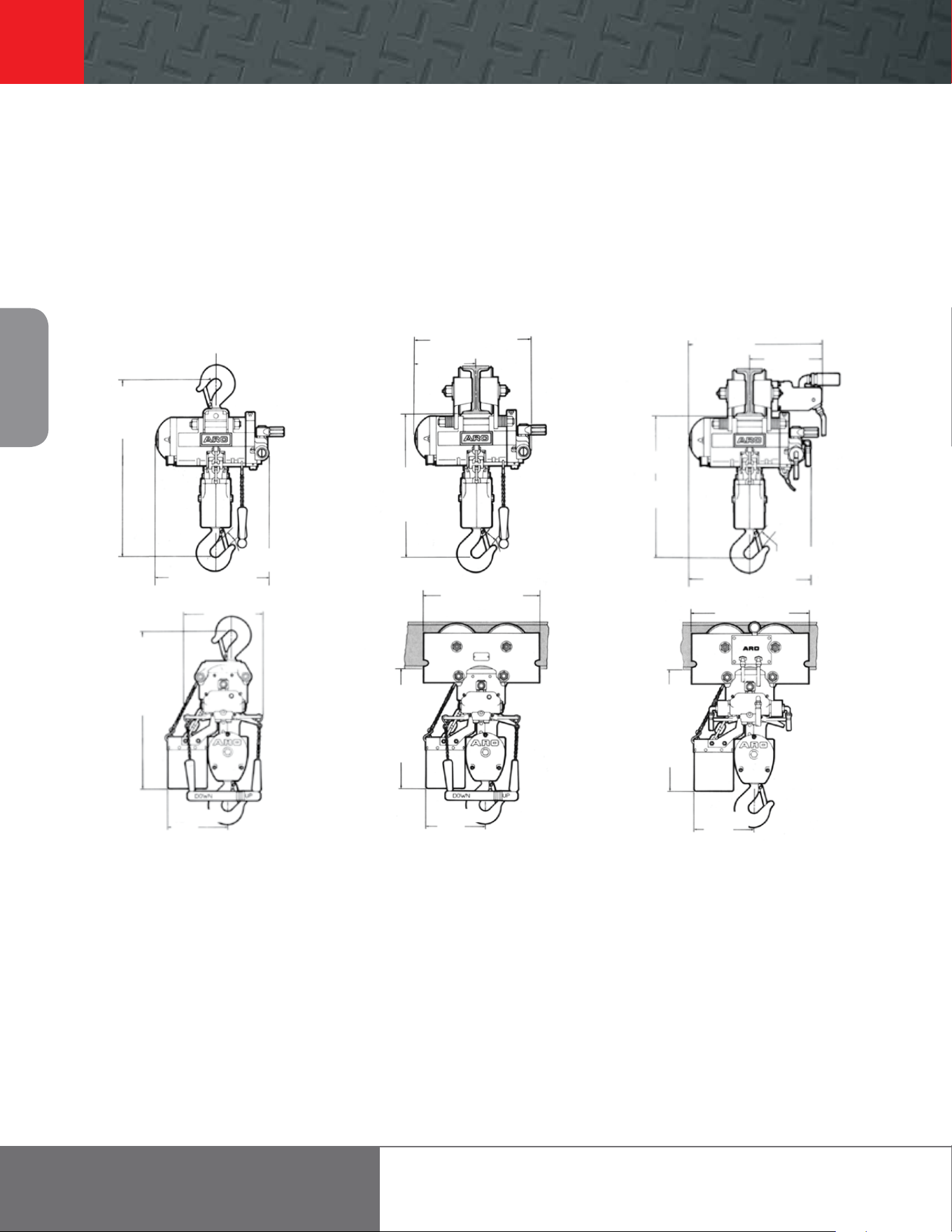
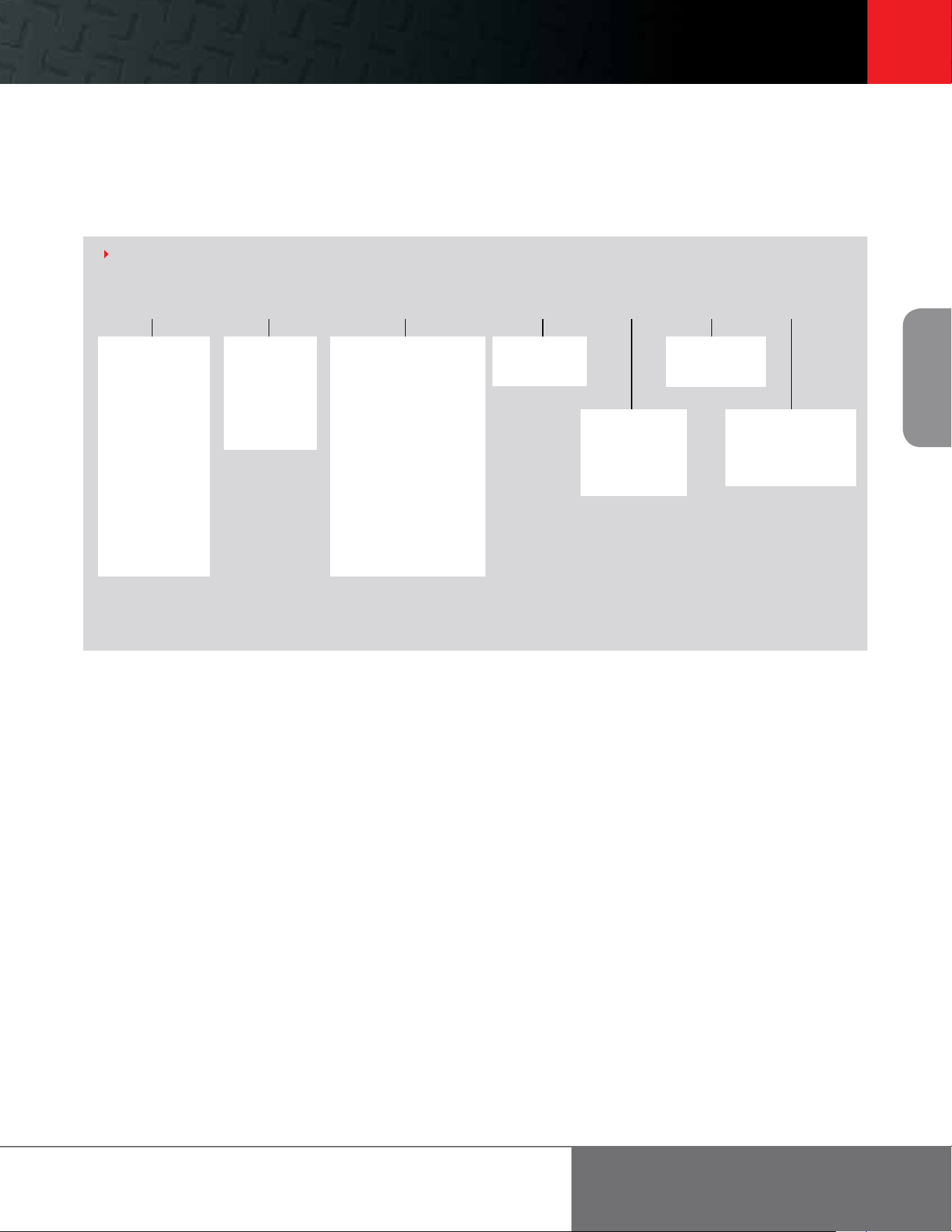
Dimensional drawings
7700 Series Air Chain Hoists
Typical headroom dimensions (A) are indicated in dimensional drawings.
Hook Mounted Trolley Mounted Motorized Trolley Mounted
1/8, 1/4 & 1/2 t Link:
17” (432 mm) min.
1/4 & 1/2 t Roller:
15-7/8” (403 mm) min.
1 t Link & Roller:
22-11/16” (551 mm) min.
A
1
10-19/32” (269 mm)
1/8, 1/4 & 1/2 t: 1” (25 mm)
1 t: 1-1/4” (32 mm)
1/8, 1/4 & 1/2 t: 8-15/16” (227 mm)
1 t: 10” (254 mm)
5” (127 mm)
B
C
14-1/2 – 15-3/4”
(368 – 400 mm)
9 – 10 -1/4”
(228 – 260 mm)
1/8, 1/4 & 1/2 t Link:
16-7/8” (428 mm) min.
1 t Link:
20-1/2” (521 mm) min.
1/4 & 1/2 t Roller:
14-3/4” (375 mm) min.
1 t Roller:
20-1/2” (521 mm) min.
A
1
1/8, 1/4 & 1/2 t: 1” (25 mm)
1 t: 1-1/4” (32 mm)
11-21/32” (296 mm)
10” (254 mm)
B
C
1/8, 1/4 & 1/2 t: 10” (254 mm)
1 t: 12-5/8” (321 mm)
2-5/8” (67 mm)
1/8, 1/4 & 1/2 t Link:
17-1/8” (435 mm) min.
1 t Link:
21-1/4” (540 mm) min.
1/4 & 1/2 t Roller
16” (406 mm) min.
1 t Roller:
21-1/4” (540 mm) min.
A
1
1/4 & 1/2 t: 1” (25 mm)
1 t: 1-1/4” (32 mm)
10-19/32 (269)
14-3/4” (375 mm)
B
C
Note:
(1) Dimension “A” for the 7700 Series 0.125-, 0.25- and 0.50-ton hoists increases 1 inch for each Bullard hook used.
Basket Hook Mt (in) Trolley Mt (in) Motorized Trly (in)
Capacity () B C B C B C
LINK TyPE
20 21 7.8 21.5 7.8 20.2 7.8
32 25.5 7.8 26 7.8 24.7 7.8
56 31.5 7.8 32 7.8 30.7 7.8
Basket Hook Mt (in) Trolley Mt (in) Motorized Trly (in)
Capacity () B C B C B C
ROLLER TyPE
10 25.4 11.2 25.9 11.2 24.9 11.2
16 29.3 14.4 29.8 14.4 28.7 14.4
40 39.9 20.6 40.4 20.6 39.4 20.6
26
Air Chain
Hoists
866-207-6923
Dimensional drawings
7790 Series Air Chain Hoists
Typical headroom dimensions (A) are indicated in dimensional drawings.
Hook Mounted Trolley Mounted Motorized Trolley Mounted
16-1/2 – 17-3/4”
(418 – 450 mm)
9 – 10-1/4”
(228 – 260 mm)
1 t:
15” (381 mm) min.
2 t:
18” (457 mm) min.
1 t: 1-1/8” (28 mm)
2 t: 1-1/4” (32 mm)
15-5/8” (397 mm)
14-3/4” (375 mm)
10’ (3 m) cap:
15-5/8” (397 mm)
20’ (6m) cap:
19-5/8” (499 mm)
40’ (12m) cap:
27-5/8” (702 mm)
1 t:
8-3/16” (208 mm)
2 t:
7-5/8” (194 mm)
14-7/32” (361 mm)
7-3/4” (197 mm)
1 t:
15” (381 mm) min.
2 t:
18” (457 mm) min.
1 t: 1-1/8” (28 mm)
2 t: 1-1/4” (32 mm)
9-7/8” (521 mm)
1’ (3 m) cap:
20-1/4” (514 mm)
20’ (6m) cap:
24-1/4” (616 mm)
40’ (12m) cap:
32-1/4” (819 mm)
1 t:
8-3/16” (208 mm)
2 t:
7-5/8” (194 mm)
1 t:
18-7/8” (479 mm) min.
2 t:
22-3/8” (568 mm) min.
1 t: 1-1/8” (28 mm)
2 t: 1-1/4” (32 mm)
14-7/32” (361 mm)
14-3/4” (375 mm)
10’ (3 m) cap:
13-27/32” (352 mm)
20’ (6 m) cap:
17-27/32” (453 mm)
40’ (12 m) cap:
25-27/32” (682 mm)
1 t:
7-29/32” (201 mm)
2 t:
7-5/8” (194 mm)
Note:
Headroom dimension for the 7790 Series 1-ton hoist increases 1.25” for each Bullard hook used.
Headroom dimension for the 7790 Series 2-ton hoist increases 1.50” for each Bullard hook used.
Footer 27
27
Air Chain
Hoists
ingersollrandproducts.com/liing
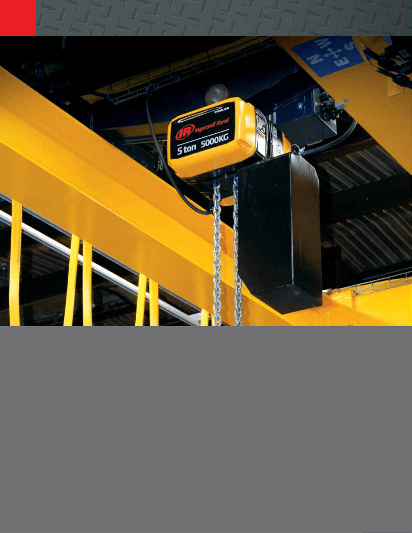
7700 Series and 7790 Series
0.125 to 2 metric ton liing capacities
Specify complete model number as shown. This model code includes: Base Model - Control Option, Upper Suspension, Li - Lower Suspension,
Control Length, and Options.
Base Control Option Li (feet) Li (feet) OptionsLower Hook– –
Zinc plated steel
link chain models:
7770E = 0.125 ton
7718E = 0.25 ton
7756E = 0.50 ton
7776E = 1 ton
7790A = 1 ton
7792A = 2 ton
Spark resistant
stainless steel link
chain models:
7712EL = 550 lb
7714EL = 1,500 lb
7796AL = 1,500 lb
7798AL = 2,400 lb
7790AL = 3,000 lb
A = Lug /adapter
C = Steel snap hook
E = Eye bolt (7740 only)
K = Bullard hook,
manual close
(3)
R = Bronze snap hook
(2)
DA = Rigid RT or TIR push
trolley A flange
DD = Rigid TIR push
trolley D flange
FxxA = Hand geared
trolley A flange
FxxD = Hand geared
trolley D flange
HA = Powered trolley
A flange
HD = Powered trolley
D flange
10 = Standard
XXX = Specify
length
C = Steel snap hook
K = Bullard hook,
manual close
(3)
G = Self latching
hook
(1) (3)
R = Bronze hook
(2)
P = Piped exhaust kit
(1)
U = Canvas chain
container
S = Steel chain
container
(1) (3)
6 = Standard
XXX = Specify
length
HOW TO ORDER
0 = No controls
1 = Pull chain
2 = Pendent
control
3 = 2 motor
pendent
4 = 3 motor
pendent
Upper Suspension
Pricing example: 7712EL-3HA20 -R16U
Spark-resistant, 550 lb capacity, stainless link chain, 1 chain fall, 50 fpm liing speed. Unit is specified with two motor pendent
control, power trolley suspension (A flange), 20 of li, bronze lower hook, 16 of pendent length and a canvas basket.
NOTES:
(2) Standard on spark-resistant models
(3) Not available on spark-resistant
models
28
866-207-6923
Electric Chain Hoists
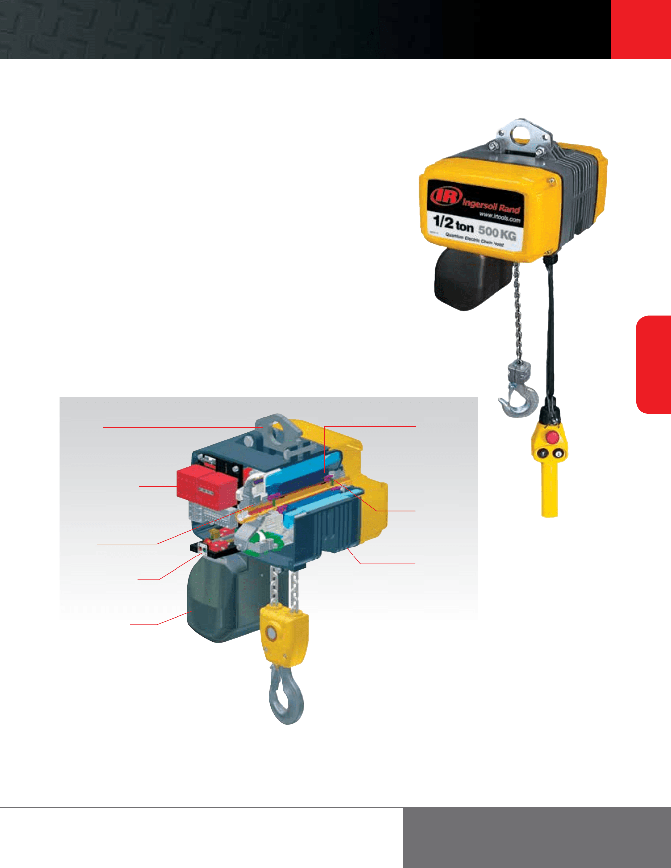
Ingersoll Rand Quantum QCH Series electric chain hoists bring outstanding control, reliability,
long life, and safety to your load handling operations. Available in both single and dual-speed
options — as well as liing capacities ranging from 0.125 to 5 ton — Quantum QCH Series
hoists meet or exceed H3 duty-cycle standards for world-class performance. They are also the
only hoist family UL and C-UL listed, with third-party evaluation limiting liability.
Quantum QCH Series hoists feature geared limit switches and pendents with e-stops as
standard. They oer low-headroom profiles and are easily customized to your application.
Footer 29
29
Electric Chain
Hoists
ingersollrandproducts.com/liing
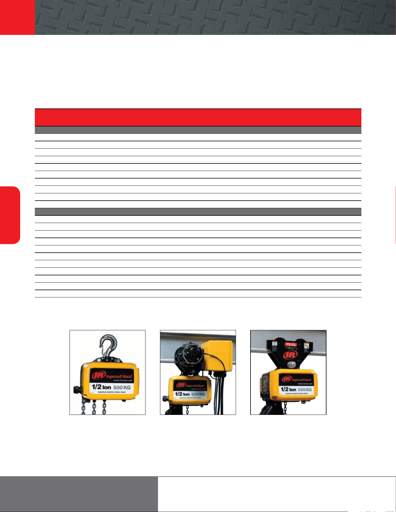
Quantum Series
0.125 to 5 metric ton liing capacities
Features
Smooth, quiet operation — Helical / spur gear combination provides smooth movement and
quiet, reliable operation. A floating chain guide precisely feeds chain onto a machine-matched,
five-pocket chain wheel. This system ensures smooth, jam-resistant operation.
Durability — Quantum load chains are precision-formed from alloy steel, case hardened and
zinc-plated. The plating is an Ingersoll Rand proprietary process that resists corrosion better
than any standard plating oered for load chain.
Reliability — With high starting torque, Quantum motors use a totally enclosed non-ventilated
(TENV) squirrel cage design. Class F insulation provides a total thermal rating of 145°C at a 1.0
service factor, instead of the more common Class B insulation of 120° C.
Safety — State-of-the-art AC motor brakes with all-steel discs. Multiple stacking significantly
increases braking surface area, reducing wear and extending life. Quantum brake discs are
guaranteed for the life of the hoist. The overload clutch is factory-set to limit Quantum from
liing loads in excess of 150% of rated hoisting capacity.
Ergonomics — Safety-first pendent control handles are comfortable and fit securely in the
operator’s hand. Each low-voltage (42-volt) control handle integrates a large, red emergency
stop button. Operating buttons are clearly marked with high contrast arrows, feature so-push
action, and are horizontally aligned for easier operation.
Gear case
Electrical controls
Motor
Eyebolt
Overload clutch
Brake
Chain container
(optional)
Cooling fins
Adjustable geared
limit switches
Load chain
30
Electric Chain
Hoists
866-207-6923
Quantum Series
0.125 to 5 metric ton liing capacities
Eyebolt and hook suspension Motorized trolley suspension PT Series plain trolley with
hook suspension
Quantum Series Specifications
Capacity Hook Mount Trolley Mount Liing Speed Lowering Speed Chain Weight Net Weight
metric
tons
Motor Headroom Headroom Rated Load or No Load Rated Load or No Load (per foot of li) w/10 of li
Model
lb # Falls hp in mm in mm /min m/min /min m/min lb kg lb kg
THREE-PHASE (SINGLE SPEED)
QCH50-1NS12 275 0.125 1 1 17.1 435 17.4 441.3 32 9.8 32 9.8 0.4 0.2 45 20.4
QCH50-1NS25 550 0.25 1 1 17.1 435 17.4 441.3 32 9.8 32 9.8 0.4 0.2 45 20.4
QCH50-1NS50 1,100 0.50 1 1 17.1 435 17.4 441.3 32 9.8 32 9.8 0.4 0.2 45 20.4
QCH50-2NS100 2,200 1 2 1 18.8 476.3 18.9 481 16 4.9 16 4.9 0.7 0.3 50 22.7
QCH100-1NS100 2,200 1 1 2.1 21.8 553.2 21.5 545.3 32 9.8 32 9.8 0.7 0.3 99 44.9
QCH100-2NS200 4,400 2 2 2.1 24.7 627.1 24.4 619.9 16 4.9 16 4.9 1.4 0.6 110 49.9
QCH300-1NS200 4,400 2 1 4.2 25.4 646.1 26.4 671.5 32 8 32 9.8 1.5 0.7 143 64.9
QCH200-2NS300 6,600 3 2 3.2 28.7 727.9 29.8 756.4 16 4.9 16 4.9 3 1.4 161 73
QCH300-2NS400 8,800 4 2 4.2 28.7 727.9 29.7 753.3 16 4.9 16 4.9 3 1.4 168 76.2
QCH500-2NS500 11,000 5 2 4.2 28.7 727.9 29.7 754.9 12.5 3.8 12.5 3.8 3 1.4 168 76.2
THREE-PHASE (DUAL SPEED)
QCH50-1ND12 275 0.125 1 1 17.1 435 17.4 441.3 32 / 8 9.8 / 2.4 32 / 8 9.8 / 2.4 0.4 0.2 50 22.7
QCH50-1ND25 550 0.25 1 1 17.1 435 17.4 441.3 32 / 8 9.8 / 2.4 32 / 8 9.8 / 2.4 0.4 0.2 50 22.7
QCH50-1HD25 550 0.25 1 1 17.1 435 17.4 441.3 50 / 12 15.2 / 3.7 50 / 12 15.2 / 3.7 0.4 0.2 50 22.7
QCH50-1ND50 1,100 0.50 1 1 17.1 435 17.4 441.3 32 / 8 9.8 / 2.4 32 / 8 9.8 / 2.4 0.4 0.2 50 22.7
QCH50-2ND100 2,200 1 2 1 18.8 476.3 18.9 481 16 / 4 4.9 / 1.2 16 / 4 4.9 / 1.2 0.7 0.3 55 24.9
QCH100-1ND100 2,200 1 1 2.1 21.8 553.2 21.5 545.3 32 / 8 9.8 / 2.4 32 / 8 9.8 / 2.4 0.7 0.3 101 45.8
QCH100-2ND200 4,400 2 2 2.1 24.7 627.1 24.4 619.9 16 / 4 4.9 / 1.2 16 / 4 4.9 / 1.2 1.4 0.6 112 50.8
QCH300-1ND200 4,400 2 1 4.2 25.4 646.1 26.4 671.5 32 / 8 9.8 / 2.4 32 / 8 9.8 / 2.4 1.5 0.7 147 66.7
QCH200-2ND300 6,600 3 2 3.2 28.7 727.9 29.8 756.4 16 / 4 4.9 / 1.2 16 / 4 4.9 / 1.2 3 1.4 165 74.8
QCH300-2ND400 8,800 4 2 4.2 28.7 727.9 29.7 753.3 16 / 4 4.9 / 1.2 16 / 4 4.9 / 1.2 3 1.4 172 78
QCH500-2ND500 11,000 5 2 4.2 28.7 727.9 29.7 754.9 12.5 / 3 3.8 / 0.9 12.5 / 3 3.8 / 0.9 3 1.4 172 78
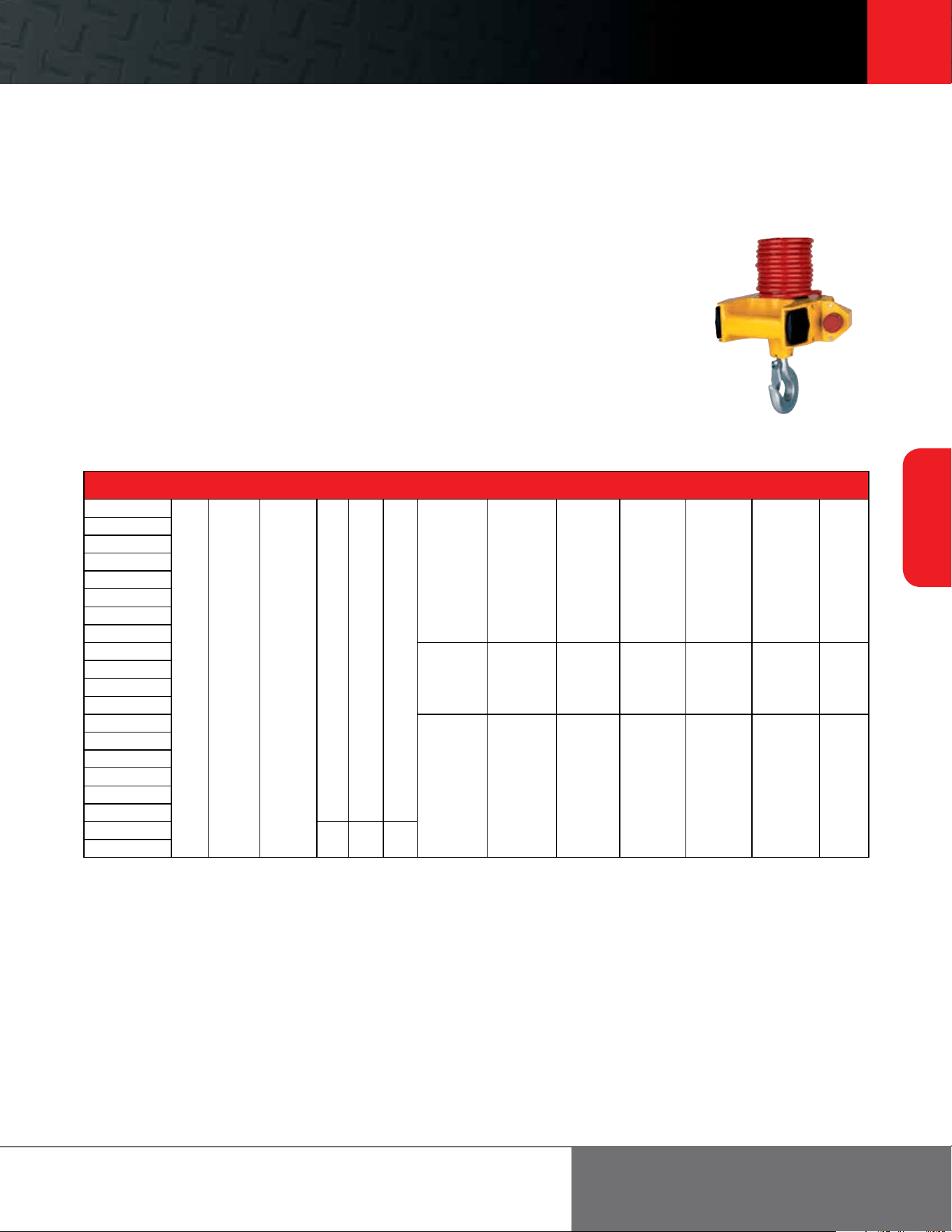
Footer 31
31
Electric Chain
Hoists
ingersollrandproducts.com/liing
Handy Handle control — QCH50 models only
This ergonomically designed control enables precise operation at the hook and acts as a robotic power extension of
the operator’s arm. The load can be positioned and controlled with one hand, freeing the other to position the load.
The Handy Handle can be ordered separately as part of a kit, to convert any 0.125-, 0.25-, and 0.50-ton single-
line Quantum hoist, or as an “H” control option on a new hoist. Each Handy Handle comes standard with single- or
dual-speed thumb control lever switches and red emergency stop button. A socket connection at the bottom allows
the standard hook to be easily replaced by custom-end eectors or grabs.
Quantum Series Motorized Trolley Specifications – M1, M2, and M4
Traverse Speed /min (m/min) Amperage Min. in (mm) Min. in (mm) Flange Width in (mm) Weight
Model
M1 M2 M4 230V 460V 575V Beam Height Curve Radius A B C D lb (kg)
QCH50-1NS12
48
(14.6)
48/16
(14.6/4.9)
72/24
(21.9/7.3)
1.5 0.75 0.6
4
(101.6)
48
(1219.2)
2.0 - 3.9
(50.8 - 99.1)
4.0 - 5.9
(101.6 - 149.9)
6.0 - 7.8
(152.4 - 198.1)
7.9 - 9.4
(200.7 - 238.8)
60
(27.2)
QCH50-1ND12
QCH50-1NS25
QCH50-1ND25
QCH50-1NS50
QCH50-1ND50
QCH50-2NS100
QCH50-2ND100
QCH100-1NS100
6
(152.4)
60
(1524.0)
3.0 - 5.5
(76.2 - 139.7)
5.6 - 7.8
(142.2 - 198.1)
7.9 - 10.2
(200.7 - 259.1)
10.3 - 12.6
(261.6 - 320.0)
70
(31.7)
QCH100-1ND100
QCH100-2NS200
QCH100-2ND200
QCH300-1NS200
6
(152.4)
72
(1828.8)
2.2 - 4.7
(55.9 - 119.4)
4.8 - 7.0
(121.9 - 177.8)
7.1 - 9.4
(180.3 - 238.8)
9.5 - 11.8
(241.3 - 299.7)
110
(49.9)
QCH300-1ND200
QCH200-2NS300
QCH200-2ND300
QCH300-2NS400
QCH300-2ND400
QCH500-2NS500
3 1.5 1.2
QCH500-2ND500
Quantum Series
0.125 to 5 metric ton liing capacities
32
Electric Chain
Hoists
866-207-6923
Quantum Series
0.125 to 5 metric ton liing capacities
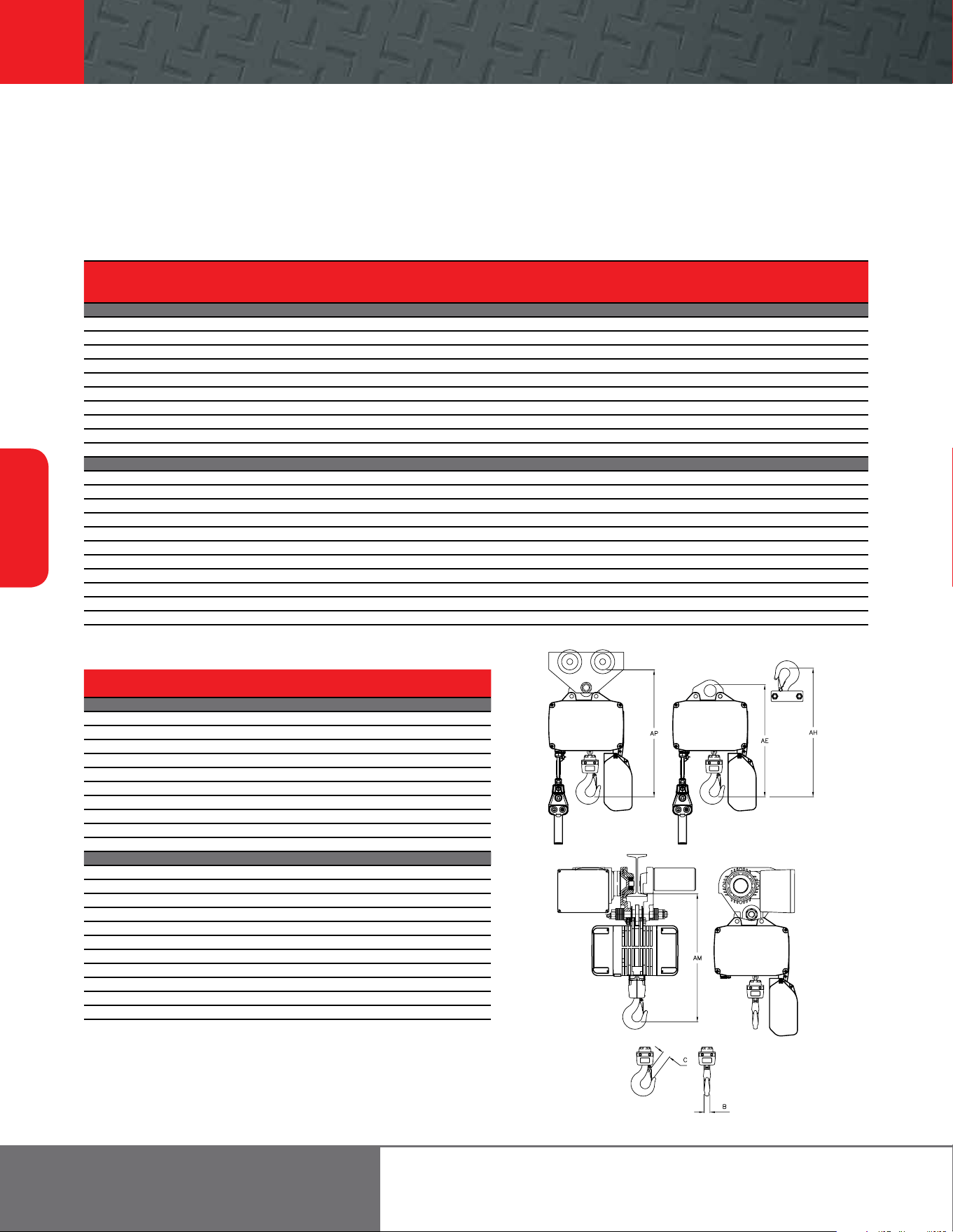
Quantum Series Dimensions
Capacity Headroom
QCH
Metric Eyebolt (AE) Hook (AH) Push Trolley (AP) Motor Trolley (AM) Hook (B) Hook (C)
Base Model
lb Tons Falls in mm in mm in mm in mm in mm in mm
THREE PHASE (SINGLE SPEED)
QCH50-1NS12 275 0.125 1 14.8 375.9 17.1 434.3 17.4 442 16.8 426.7 0.9 22.9 1 25.4
QCH50-1NS25 550 0.25 1 14.8 375.9 17.1 434.3 17.4 442 16.8 426.7 0.9 22.9 1 25.4
QCH50-1NS50 1,100 0.50 1 14.8 375.9 17.1 434.3 17.4 442 16.8 426.7 0.9 22.9 1 25.4
QCH50-2NS100 2,200 1 2 16.4 416.6 18.8 477.5 18.9 480.1 18.3 464.8 0.9 22.9 1 25.4
QCH100-1NS100 2,200 1 1 19 482.6 21.8 553.7 21.5 546.1 21.3 541 1 25.4 1.3 33
QCH100-2NS200 4,400 2 2 21.9 556.3 24.7 627.4 24.4 619.8 24.3 617.2 1 25.4 1.3 33
QCH300-1NS200 4,400 2 1 23.9 607.1 25.4 645.2 26.4 670.6 26.2 665.5 1.5 38.1 1.6 40.6
QCH200-2NS300 6,600 3 2 27.2 690.9 28.7 729 29.8 756.9 29.3 744.2 1.5 38.1 1.6 40.6
QCH300-2NS400 8,800 4 2 27.2 690.9 28.7 729 29.7 754.4 29.3 744.2 1.5 38.1 1.6 40.6
QCH500-2NS500 11,000 5 2 27.2 690.9 28.7 729 29.7 754.4 29.3 744.2 1.5 38.1 1.6 40.6
THREE PHASE (DUAL SPEED)
QCH50-1ND12 275 0.125 1 14.8 375.9 17.1 434.3 17.4 442 16.8 426.7 0.9 22.9 1 25.4
QCH50-1ND25 550 0.25 1 14.8 375.9 17.1 434.3 17.4 442 16.8 426.7 0.9 22.9 1 25.4
QCH50-1HD25 550 0.25 1 14.8 375.9 17.1 434.3 17.4 442 16.8 426.7 0.9 22.9 1 25.4
QCH50-1ND50 1,100 0.50 1 14.8 375.9 17.1 434.3 17.4 442 16.8 426.7 0.9 22.9 1 25.4
QCH50-2ND100 2,200 1 2 16.4 416.6 18.8 477.5 18.9 480.1 18.3 464.8 0.9 22.9 1 25.4
QCH100-1ND100 2,200 1 1 19 482.6 21.8 553.7 21.5 546.1 21.3 541 1 25.4 1.3 33
QCH100-2ND200 4,400 2 2 21.9 556.3 24.7 627.4 24.4 619.8 24.3 617.2 1 25.4 1.3 33
QCH300-1ND200 4,400 2 1 23.9 607.1 25.4 645.2 26.4 670.6 26.2 665.5 1.5 38.1 1.6 40.6
QCH200-2ND300 6,600 3 2 27.2 690.9 28.7 729 29.8 756.9 29.3 744.2 1.5 38.1 1.6 40.6
QCH300-2ND400 8,800 4 2 27.2 690.9 28.7 729 29.7 754.4 29.3 744.2 1.5 38.1 1.6 40.6
QCH500-2ND500 11,000 5 2 27.2 690.9 28.7 729 29.7 754.4 29.3 744.2 1.5 38.1 1.6 40.6
Quantum Series Weight
QCH
Eyebolt or Hook Push Trolley Motor Trolley
Base Model
lb kg lb kg lb kg
THREE PHASE (SINGLE SPEED)
QCH50-1NS12 45 20.4 65 29.5 105 47.6
QCH50-1NS25 45 20.4 65 29.5 105 47.6
QCH50-1NS50 45 20.4 65 29.5 105 47.6
QCH50-2NS100 50 22.7 80 36.3 110 49.9
QCH100-1NS100 99 44.9 129 58.5 173 78.5
QCH100-2NS200 110 49.9 165 74.8 184 83.4
QCH300-1NS200 143 64.9 198 89.8 257 116.6
QCH200-2NS300 161 73 236 107 281 127.4
QCH300-2NS400 168 76.2 274 124.3 282 127.9
QCH500-2NS500 168 76.2 274 124.3 282 127.9
THREE PHASE (DUAL SPEED)
QCH50-1ND12 50 22.7 70 31.7 110 49.9
QCH50-1ND25 50 22.7 70 31.7 110 49.9
QCH50-1HD25 50 22.7 70 31.7 110 49.9
QCH50-1ND50 50 22.7 70 31.7 110 49.9
QCH50-2ND100 55 24.9 85 38.5 115 52.2
QCH100-1ND100 101 45.8 131 59.4 175 79.4
QCH100-2ND200 112 50.8 167 75.7 186 84.4
QCH300-1ND200 147 66.7 202 91.6 261 118.4
QCH200-2ND300 165 74.8 240 108.8 285 129.3
QCH300-2ND400 172 78.0 278 126.1 286 129.7
QCH500-2ND500 172 78.0 278 126.1 286 129.7
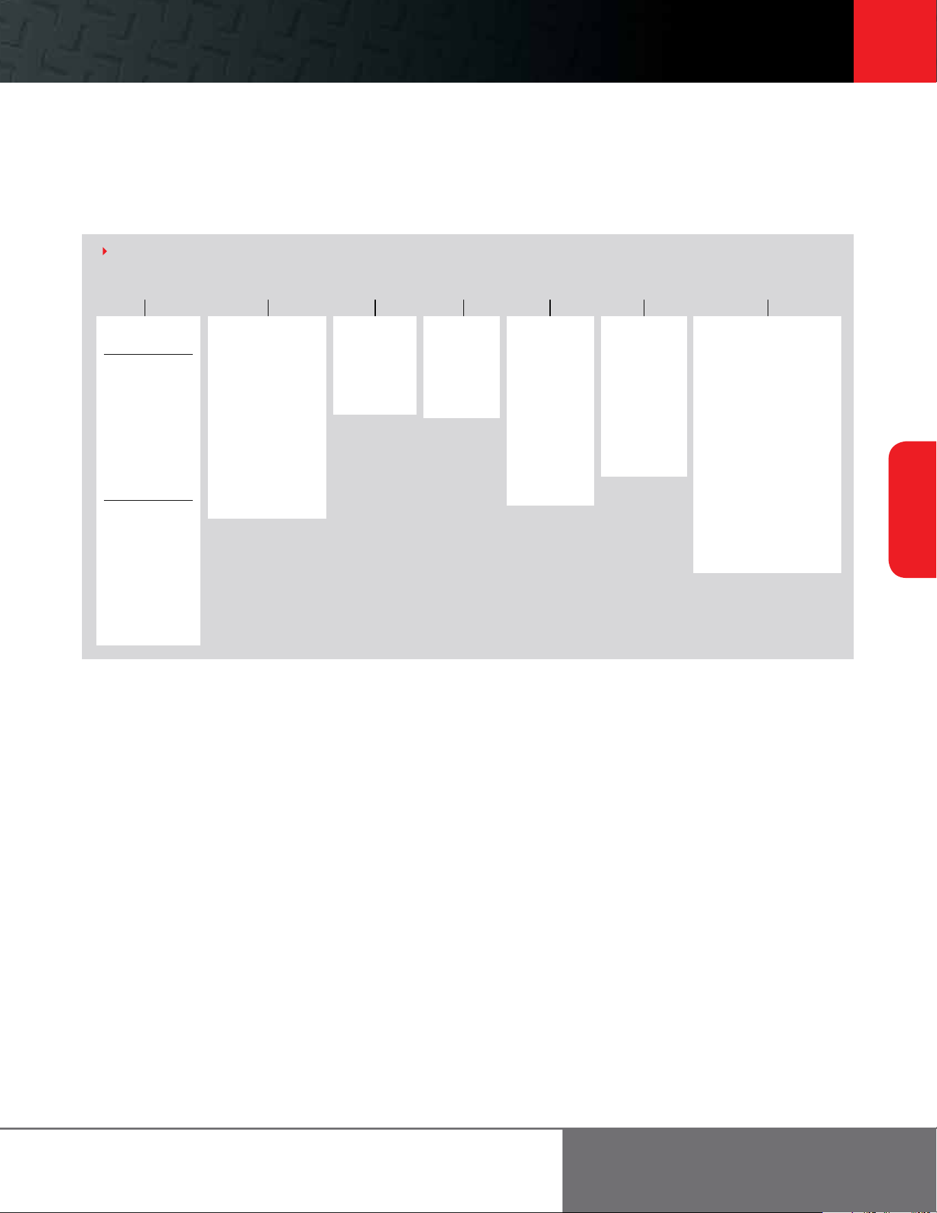
Footer 33
33
Electric Chain
Hoists
ingersollrandproducts.com/liing
Example: QCH100-2NS200M1-21-17B4C
QCH100-2NS200 M1 21 17 B C4– –
Base model
3 phase single speed
QCH50-1NS12
QCH50-1NS25
QCH50-1NS50
QCH50-2NS100
QCH100-1NS100
QCH100-2NS200
QCH300-1NS200
QCH200-2NS300
QCH300-2NS400
QCH500-2NS500
3 phase dual-speed
QCH50-1ND12
QCH50-1ND25
QCH50-1HD25
QCH50-1ND50
QCH50-2ND100
QCH100-1ND100
QCH100-2ND200
QCH300-1ND200
QCH200-2ND300
QCH300-2ND400
QCH500-2ND500
Li (feet)
10 = Standard
15 = Standard
20 = Standard
XX = Specify
length
Pendent
drop (feet)
6 = Standard
11 = Standard
16 = Standard
XX = Specify
length
Flange width
(See catalog for
specifications)
- = Eye bolt
or hook
mount
A = See flange
width chart
B = See flange
width chart
C = See flange
width chart
D = See flange
width chart
Options
B = Trolley brake
C = Chain container
E = External strain relief
F = XX, specify power cord
length (standard is 15
on E, H, and P, and 3
on M1-M4 suspensions)
H = Handy Handle
(QCH50 single fall only)
K = 110 volt control (3
phase models only)
P = Pendent with vertical
aligned buttons
P2 = Pendent with 2 extra
vertical aligned buttons
P4 = Pendent with 4 extra
vertical aligned buttons
Y = Bullard top hook
Z = Bullard bottom hook
Voltage
3 = 230/3/60
4 = 460/4/60
5 = 575/3/60
6 =
380/3/50*
(* = these units
have extended
lead times and
are not UL or
C-UL (Canadian
UL) listed)
HOW TO ORDER
Suspension type
E = Eye bolt
H = Hook
P = Plain trolley (“PT”
Series)
M1 = Motorized trolley
(normal speed 48
fpm)
M2 = Motorized trolley
(normal/dual
speed 48/16
fpm)
M4 = Motorized trolley
(high/dual speed
96/24 fpm)
Quantum Series
0.125 to 5 metric ton liing capacities
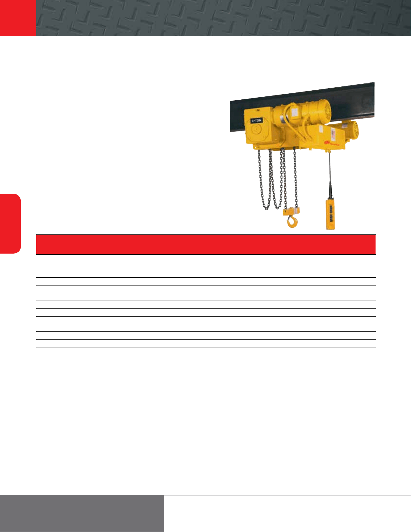
34
Electric Chain
Hoists
866-207-6923
Features
The complete line of low-headroom Ingersoll Rand worm-gear-driven electric and
air hoists provides smooth, quiet, trouble-free operation. All models are tested in
accordance with ANSI B30.16 overhead hoist standards.
• Large-diameter chain wheels for improved chain wear
• Worm gear drive for maximum control and durability
• Plain, motorized, and hand chain trolleys
• Dual up and down limits for added safety
• NEMA-12 enclosure for weather-resistant pendent controls
• Design flexibility allows custom configurations to be oered and priced on request
• Dual- and self-braking worm drive and spring-applied motor brake
• Explosion-proof units and spark- and corrosion-resistant features can be
customized to fit applications and priced on request
• Quick response time to quotes and reduced lead time on delivery
ULE2 Ultra-Lo Series
0.25 to 24 ton liing capacity
ULE2 Electric Series Specifications
Trolley Mount Liing Speed Lowering Speed Net Weight Net Weight Net Weight
Capacity Motor Headroom Rated Load or No Load Rated Load or No Load Plain Trolley Geared Trolley Motorized Trolley
Model
lb U.S. tons # Falls hp in mm /min m/min /min m/min lb kg lb kg lb kg
ULE2_010-8-6 2,000 1 N/A 2 7 177.8 10 3.1 10 3.1 440 199.5 470 213.2 480 217.7
ULE2_015-8-6 3,000 1.5 N/A 2 7 177.8 10 3.1 10 3.1 440 199.5 470 213.2 480 217.7
ULE2_020-8-6 4,000 2 N/A 2 7 177.8 10 3.1 10 3.1 440 199.5 470 213.2 480 217.7
ULE2_030-8-6 6,000 3 N/A 2 8 203.2 5 1.5 5 1.5 540 244.9 570 258.5 580 263
ULE2_040-8-6 8,000 4 N/A 2 8.5 215.9 5 1.5 5 1.5 540 244.9 570 258.5 580 263
ULE2_050-8-6 10,000 5 N/A 4 9.5 241.3 7 2.1 7 2.1 1,280 580.5 1,340 607.7 1,310 594.1
ULE2_060-8-6 12,000 6 N/A 4 9.5 241.3 7 2.1 7 2.1 1,280 580.5 1,340 607.7 1,310 594.1
ULE2_080-8-6 16,000 8 N/A 4 12 304.8 4 1.2 4 1.2 1,350 612.2 1,480 671.2 1,400 634.9
ULE2_100-8-6 20,000 10 N/A 4 12.5 317.5 3.5 1.1 3.5 1.1 1,730 784.6 1,810 820.9 1,780 807.3
ELE2_120-8-6* 24,000 12 N/A 4 12.5 317.5 3.5 1.1 3.5 1.1 1,730 784.6 1,810 820.9 1,780 807.3
ULE2_160-8-6* 32,000 16 N/A 4 14.5 368.3 2 0.6 2 0.6 2,300 1043.1 2,380 1079.4 2,350 1065.8
ULE2_200-8-6* 40,000 20 N/A 4 18 457.2 1.7 0.5 1.7 0.5 2,650 1201.8 2,810 1274.4 2,750 1247.2
ULE2_240-8-6* 48,000 24 N/A 4 18 457.2 1.7 0.5 1.7 0.5 2,650 1201.8 2,810 1274.4 2,750 1247.2
Notes:
Standard li is 10 .
* For over 10 U.S. ton capacity, straight track operation is recommended.
Curved radius must be specified on orders, since wheels must be modified to negotiate curves.
Curves less than minimum radius may be fitted upon application. Consult Customer Service for further information.
ULA2 air hoist specifications and dimensions are similar. Consult Customer Service if accurate data is required.
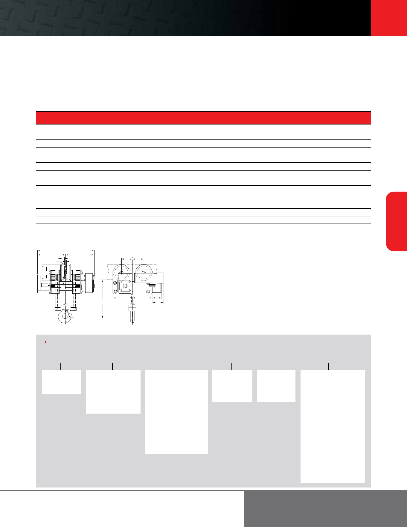
Footer 35
35
Electric Chain
Hoists
ingersollrandproducts.com/liing
B
(1)
D
(1)
C
L
P
H
S
M
N
J
A
E E
F G R
T
(1)
ULE2 Series Dimensions†
A B C D E E1 F G H J L M N P* R S T**
Model in in in in in in in in in in in in in in in in in
ULE2_010-8-6 7 33 16.5 16.5 7.8 7.8 12 10 0.6 1.1 1.1 4.5 0.9 S6X12.5 6 6 9.3
ULE2_015-8-6 7 33 16.5 16.5 7.8 7.8 12 10 0.6 1.1 1.1 4.5 0.9 S6X12.5 6 6 9.3
ULE2_020-8-6 7 33 16.5 16.5 7.8 7.8 12 10 0.6 1.1 1.1 4.5 0.9 S6X12.5 6 6 9.3
ULE2_030-8-6 8 33 16.5 16.5 9 9 14 13 0.6 1.3 1.3 6.4 1 S8X18.4 6 8 5.5
ULE2_040-8-6 8.5 33 16.5 16.5 9 9 14 13 0.6 1.7 1.3 6.4 1 S8X18.4 6 8 5.5
ULE2_050-8-6 9.5 50.5 23.5 24.9 7.4 7.4 12 15 0.9 1.7 1.4 7.2 0.9 S10X25.4 6 9 12
ULE2_060-8-6 9.5 50.5 23.5 24.9 7.4 7.4 12 15 0.9 1.7 1.4 7.2 0.9 S10X25.4 6 9 12
ULE2_080-8-6 12 50.5 23.5 24.9 8.4 8.9 14 13.5 0.6 2.1 1.7 8.3 1.1 S10X25.4 6 10 12
ULE2_100-8-6 12.5 50.5 23.5 24.9 8.5 9.8 15.6 14.4 0.6 2.3 1.8 9.8 0.9 S12X31.8 6 11.7 10
ULE2_120-8-6 12.5 50.5 23.5 24.9 8.5 9.8 15.6 14.4 0.6 2.3 1.8 9.8 0.9 S12X31.8 6 11.7 10
ULE2_160-8-6 14.5 54.5 25.5 26.9 11.9 11.9 18.6 18.6 0.6 3 2 11.8 1 S15X42.9 6 13.5 3.5
ULE2_200-8-6 18 54.5 25.5 26.9 12.1 12.4 19.3 19 0.8 3.6 2 11.8 1 S18X54.7 6 13.5 2.5
ULE2_240-8-6 18 54.5 25.5 26.9 12.1 12.4 19.3 19 0.8 3.6 2 11.8 1 S18X54.7 6 13.5 2.5
Notes:
†ULA2 air hoist specifications and dimensions are similar. Consult Customer Service for further information.
*Minimum standard I-beam for proper wheel running clearance. Contact factory for smaller beams. Customer must verify beam is adequate for applied loads.
**For standard motor and brake only.
Example: ULE2-MT-010-10-6TW
ULE2 MT 010 10 6 TW–– – –
Base model
ULA2 = Air
ULE2 = Electric
Capacity
010 = 909 kg = 2,000 lb
015 = 1364 kg = 3,000 lb
020 = 1818 kg = 4,000 lb
030 = 2727 kg = 6,000 lb
040 = 3636 kg = 8,000 lb
050 = 4545 kg = 10,000 lb
060 = 5455 kg = 12,000 lb
080 = 7273 kg = 16,000 lb
100 = 9091 kg = 20,000 lb
120 = 10909 kg = 24,000 lb
160 = 14545 kg = 32,000 lb
200 = 18182 kg = 40,000 lb
240 = 21818 kg = 48,000 lb
Li ()
10 = 10
(standard)
XX = Specify
length
Pendent drop
6 = 6
(standard)
XX = Specify
length
Options
C = Chain container
X = Electric mainline power
interrupt and pendent
buttons
W = Electric (NEMA 4)
watertight control
box, limit switches and
pendent
T = Electric thermal overload
relays — each single
speed motor
L = Electric fused control
per leg of transformer
secondary
E = Electric motor fuses —
single speed hoist
F = Electric motor fuses —
single speed hoist and
trolley
HOW TO ORDER
Trolley options
PT = Plain tapered
PF = Plain flat
MT = Motorized tapered
MF = Motorized flat
GT = Geared tapered
GF = Geared flat
NOTES:
S*COR*E options and marine finish are available.
Consult factory for flange widths over - 6” up to 1 t - 6.625” up to 1.50 and 2 t
7.25” on 3 and 4 t - 8.25” on 5 to 12 t.
Ultra-Lo hoists are not adjustable for varying beam sizes.
Beam type, size, height, width and curve radius required for all orders.
Customer to verify their beam is adequate for loads applied.
ULE2 Ultra-Lo Series
0.25 to 24 ton liing capacity
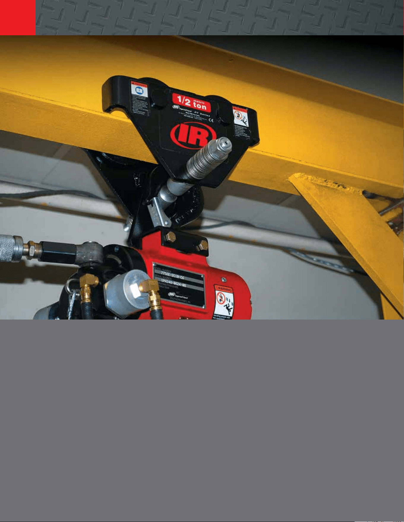
36
Trolleys and
Beam Clamps
866-207-6923
Ingersoll Rand oers a wide variety of plain, geared, or powered trolleys for use with all
Ingersoll Rand hoists. We also oer the MTK air-powered tractor to push and pull a trolley-
mounted hoist or other suspended or supported rolling load. Ingersoll Rand trolleys are available
in either hook-on or rigid-mount styles.
For maximum convenience and liing system integrity, we recommended ordering the trolley at
the same time as the hoist by using the appropriate model-driver suspension code. Information
relating to the various trolleys and MTK Series tractor can be found on the following pages.
Trolleys and Beam Clamps
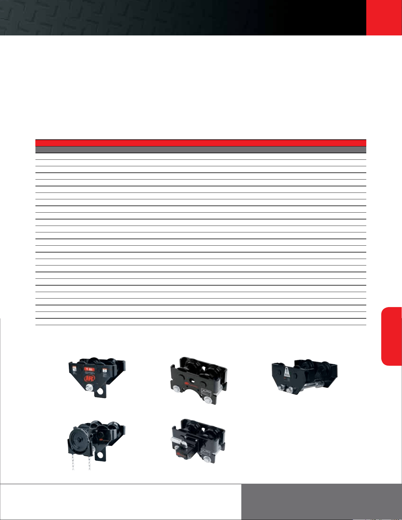
Footer 37
37
Trolleys and
Beam Clamps
ingersollrandproducts.com/liing
Trolley selection guide
0.50 to 20 metric ton liing capacities
PT Series TIR Series
TIR Series
RT Series
GT Series
The chart below cross-references all air chain hoist models and sizes with recommended trolleys. Always follow safe
installation and operating procedures with any overhead system. Please call an authorized Ingersoll Rand distributor or
representative for assistance with application and selection.
Hoist / Trolley Selection Guide
For Use With Hoist Series
Plain Hook-on Plain Rigid Geared Hook-on Geared Rigid Motorized Rigid
STANDARD TROLLEyS (SUSPENSION CODE)*
ML250 / 500K / KS PT005-8 RT010S-P00AN GT010-8-10 RT010S-G08AN RT010S-307AN
ML1000K / S PT010-8 RT010S-P00AM GT010-8-10 RT010S-G08AM RT010S-307AM
ML250KR PT005-8SB RT010B-P00AN GT010-8-10SB RT010S-G08AN RT010S-307AN
ML500KR PT005-8SB RT010B-P00AM GT010-8-10SB RT010S-G08AM RT010S-307AM
HL1000K PT010-8 TIR6600S-P00AJ GT010-8-10 TIR6600S-G08AJ TIR6600S-307AJ
HL1000KR PT010-8SB TIR6600B-P00AJ GT010-8-10SB TIR6600B-G08AJ TIR6600B-307AJ
HL1500K PT020-8 TIR6600S-P00AJ GT020-8-10 TIR6600S-G08AJ TIR6600S-307AJ
HL2000K PT020-8 TIR6600S-P00AK GT020-8-10 TIR6600S-G08AK TIR6600S-307AK
HL3000K PT030-8 TRI6600S-P00AK GT030-8-10 TIR6600S-G08AK TIR6600S-307AK
HL4500K PT050-8 TIR132S-P00AP GT050-8-10 TIR132S-G08AP TIR132S-307AP
HL6000K TIR132S-P00H TIR132S-P00AP GT050-8-10 TRI132S-G08AP TIR132S-307AP
7700 Series <1 ton PT005-8 RT010S-P00AR GT010-8-10 RT010S-G08AR RT010S-307AR
7700 Series 1 ton PT010-8 RT010S-P00AR GT010-8-10 RT010S-G08AR RT010S-307AR
7790 Series 1 ton PT010-8 TIR6600S-P00AA GT010-8-10 TIR6600S-G08AA TIR6600S-307AA
7792 Series PT020-8 TIR6600S-P00AA GT020-8-10 TIR6600S-G08AA TIR6600S-307AA
7700 Series Spark Resistant PT005-8SB RT010B-P00AR GT010-8-10SB RT010S-G08AR RT010S-307AR
7796AL Spark Resistant PT010-8SB TIR6600B-P00AA GT010-8-10SB TIR6600B-G08AA TIR6600B-307AA
7798AL / 7799AL Spark Resistant PT020-8SB TIR6600B-P00AA GT020-8-10SB TIR6600B-G08AA TIR6600B-307AA
Quantum QCH50-1 PT005-8 N/A GT010-8-10 N/A QMT50
Quantum QCH50-2 PT010-8 N/A GT010-8-10 N/A QMT50
Quantum QCH100-1 PT010-8 N/A GT010-8-10 N/A QMT150
Quantum QCH100-2 PT020-8 N/A GT020-8-10 N/A QMT150
Quantum QCH200-2 PT030-8 N/A GT030-8-10 N/A QMT300
Quantum QCH300-1 PT020-8 N/A GT020-8-10 N/A QMT300
Quantum QCH300-2 PT050-8 N/A GT050-8-10 N/A QMT300
Quantum QCH500-2 PT050-8 N/A GT050-8-10 N/A QMT300
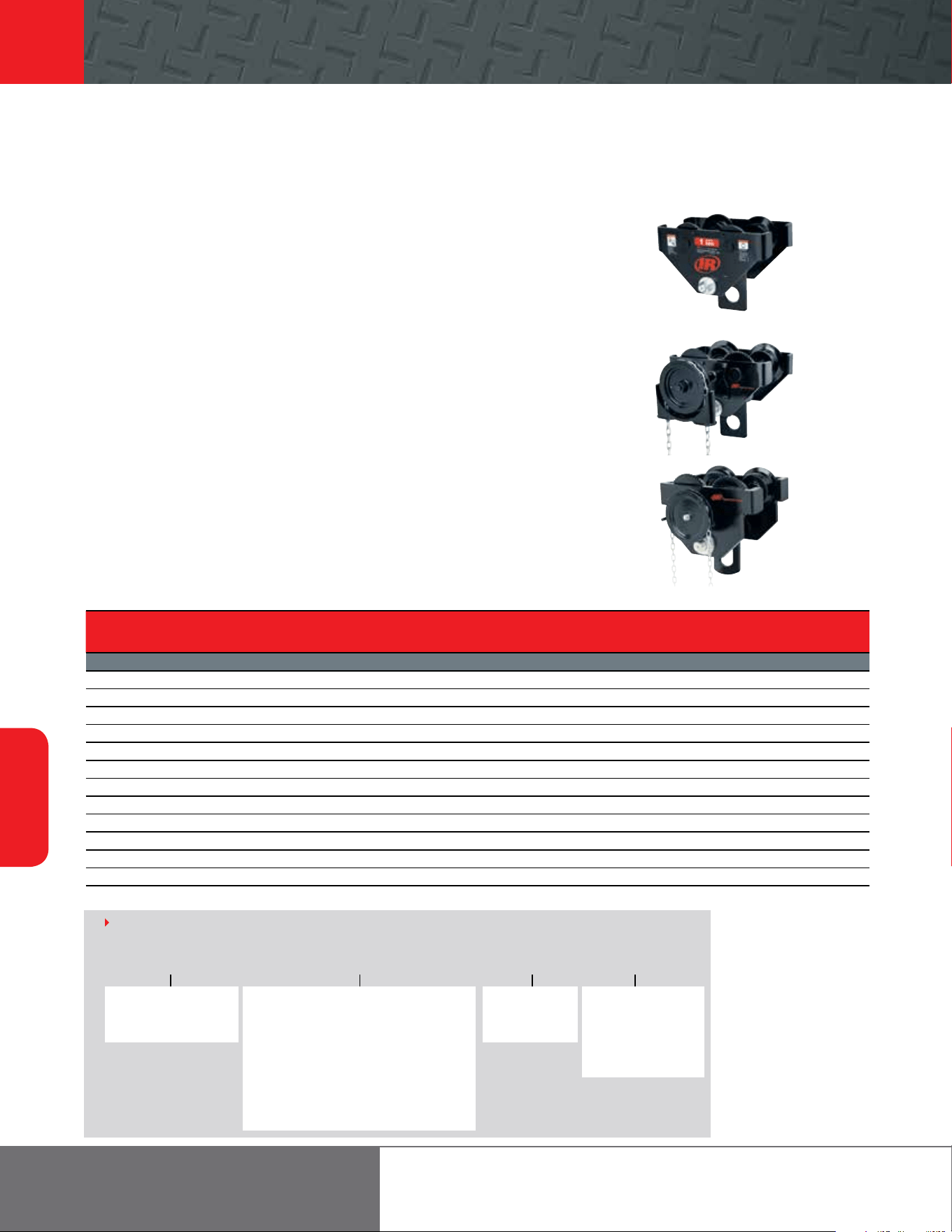
38
Trolleys and
Beam Clamps
866-207-6923
PT and GT Series trolley
0.50 to 20 metric ton capacities
Features
PT plain and GT hand-geared hook-on style trolley rated for manual or powered
hoists having the versatility to fit most types of beams with compatibility to all
hoist brands.
• The 5:1 design factor allows use with both manual or powered hoists. Meets pertinent
U.S. (ASME/ANSI and CMAA), Canadian and European standards
• The side plates, including the rail sweeps/drop stops, are made of cold-formed steel for
strength, durability, and even load distribution
• The wheels are cast iron and the universal tread fits either flat or tapered beams
• Wheels run on sealed, “Lube-for-Life” ball bearings. Smoother rolling with less eort
and maintenance
• Additional gearing in the 20-ton trolley allows operation by one hand chain
• Painted black for coordination with hoists of all colors
Options
• FDA-approved nickel composite plated finish for corrosion resistance — available on
PT005 and PT010 only
• Solid bronze alloy wheels for maximum spark resistance
• Wider hanger sha capabilities allow standard trolleys to fit almost any S-beam or
patented track beam, extension sha kits are stocked
PT010-8
GT020-8-10
GT100-12-10
Series
GT = Hand-geared hook-on
PT = Push hook-on
HOW TO ORDER
Example: GT010-8-SB
Options
NC = Nickel-plated trolley
(available on PT
Series 0.5 and 1 ton
models only)
SB = Bronze wheels
GT Series
010 = 1 metric ton
020 = 2 metric tons
030 = 3 metric tons
050 = 5 metric tons
100 = 10 metric tons
200 = 20 metric tons
Capacity
PT Series
005 = 0.5 metric tons
010 = 1 metric ton
020 = 2 metric tons
030 = 3 metric tons
050 = 5 metric tons
100 = 10 metric tons
Hand chain drop
GT Series only
Feet
PT and GT Series Hook-on Trolley Specifications
Model
Capacity
Flange
Adjustment
Min. Beam
Height Min. Curve Radius Weight
Wide Flange
Kit no.
Flange
Adjustment Weight
lb metric tons in in in lb (order separate) in lb
STANDARD SERIES
PT005-8 1,100 0.50 2.6 - 8 4 36 19.7 PT005-WFK 8 - 13 5.5
PT010-8 2,200 1 3 - 8 5 36 30.7 PT010-WFK 8 - 13 9.5
PT020-8 4,400 2 3.3 - 8 6 48 60.5 PT020-WFK 8 - 13 10
PT030-8 6,600 3 3.9 - 8 7 42 73.2 PT030-WFK 8 - 13 16.3
PT050-8 11,000 5 4.6 - 8 8 60 110.3 PT050-WFK 8 - 13 24.8
PT100-12 22,000 10 7 - 13 10 83 205 NA NA NA
GT010-8-10 2,200 1 3 - 8 5 36 43.7 PT010-WFK 8 - 13 9.5
GT020-8-10 4,400 2 3.3 - 8 6 48 73.5 PT020-WFK 8 - 13 10
GT030-8-10 6,600 3 3.9 - 8 7 42 86.2 PT030-WFK 8 - 13 16.3
GT-050-8-10 11,000 5 4.6 - 8 8 60 123.3 PT050-WFK 8 - 13 24.8
GT100-12-10 22,000 10 7 - 13 10 83 227 NA NA NA
GT200-12 44,000 20 7 - 13 12 138 540 NA NA NA
GT 010 - 8 - SB
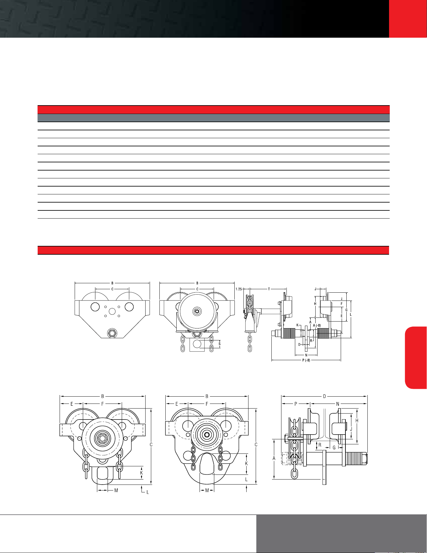
Footer 39
39
Trolleys and
Beam Clamps
ingersollrandproducts.com/liing
PT and GT Series trolley
0.50 to 20 metric ton capacities
PT010 - PT050
plain trolley/without tag
GT100
geared trolley
PT010 - PT050 and GT010 -
GT050
plain and geared trolley
GT100 and GT200
geared trolley
GT010 - GT050
geared trolley
GT200
geared trolley
PT Trolley Adapters
Stationary
Adapter comes with any 7700 Series hoist ordered as a trolley-suspended model. Adapter can be ordered separately to convert existing hook-suspended 7700 Series hoists for stationary
mounting to a PT Series trolley. Order 47717 (shown) for 0.25- and 0.50-ton models; 47716 for 1-ton models. Spacer kits are required. Refer to the price list for details.
PT and GT Series Hook-on Trolley Dimensions (in)
Model A A(-8) B C D E F G H J K L M N P P(-8) R S T
STANDARD SERIES
PT005-8 2.6 5.9 10 4.5 1 4 1.1 3.5 2.1 0.8 .1 6.6 – 3.9 – 12.3 1.3 1.6 –
PT010-8 2.5 5.9 13 5.2 1.3 4.4 1.6 4.2 2.8 0.8 1 6.9 – 4.3 – 12.9 1.5 1.6 –
PT020-8 2.6 6.1 14.6 6.8 1.3 5.3 1.3 5.8 4.3 1.1 1.2 7.5 - 4.3 - 13.8 1.5 1.6 -
PT030-8 2.6 7.9 14 6.4 1.6 5.5 1.6 5.8 4.5 1.1 1.4 8.6 - 5.4 - 14.1 1.9 2.6 -
PT050-8 2.8 8.1 15.5 7.1 1.6 5.8 2.2 6.2 4.5 1.6 1.4 9.8 - 6.6 - 15.6 2.5 2.6 -
PT100-12 11.8 - 17.9 19.3 20.8 5 7.9 2 7.4 5.9 4.2 1.8 3.2 17.1 3.7 - 1 - -
GT010-8-10 2.5 5.9 13 5.2 1.3 4.4 1.6 4.2 2.8 0.8 1 6.9 - 4.3 - 12.9 1.5 1.6 7.8
GT020-8-10 2.6 6.1 14.9 6.8 1.3 5.3 1.3 5.8 4.3 1.1 1.2 7.5 - 4.3 - 13.8 1.5 1.6 7.8
GT030-8-10 2.6 7.9 14 6.4 1.6 5.5 1.6 5.8 4.5 1.1 1.4 8.6 - 5.4 - 14.1 1.9 2.6 8.1
GT050-8-10 2.8 8.1 15.5 7.1 1.6 5.8 2.2 6.2 4.5 1.6 1.4 9.8 - 6.6 - 15.6 2.5 2.6 8.5
GT100-12-10 11.8 – 17.9 19.3 20.8 5 7.9 2 7.4 5.9 4.2 1.8 3.2 17.1 3.7 – 1 – –
GT200-12-10 10.5 – 25.3 24.5 22.5 6.7 11.8 2.6 10.8 7.9 5.9 2.8 4.3 18 4.5 – 4.9 – –
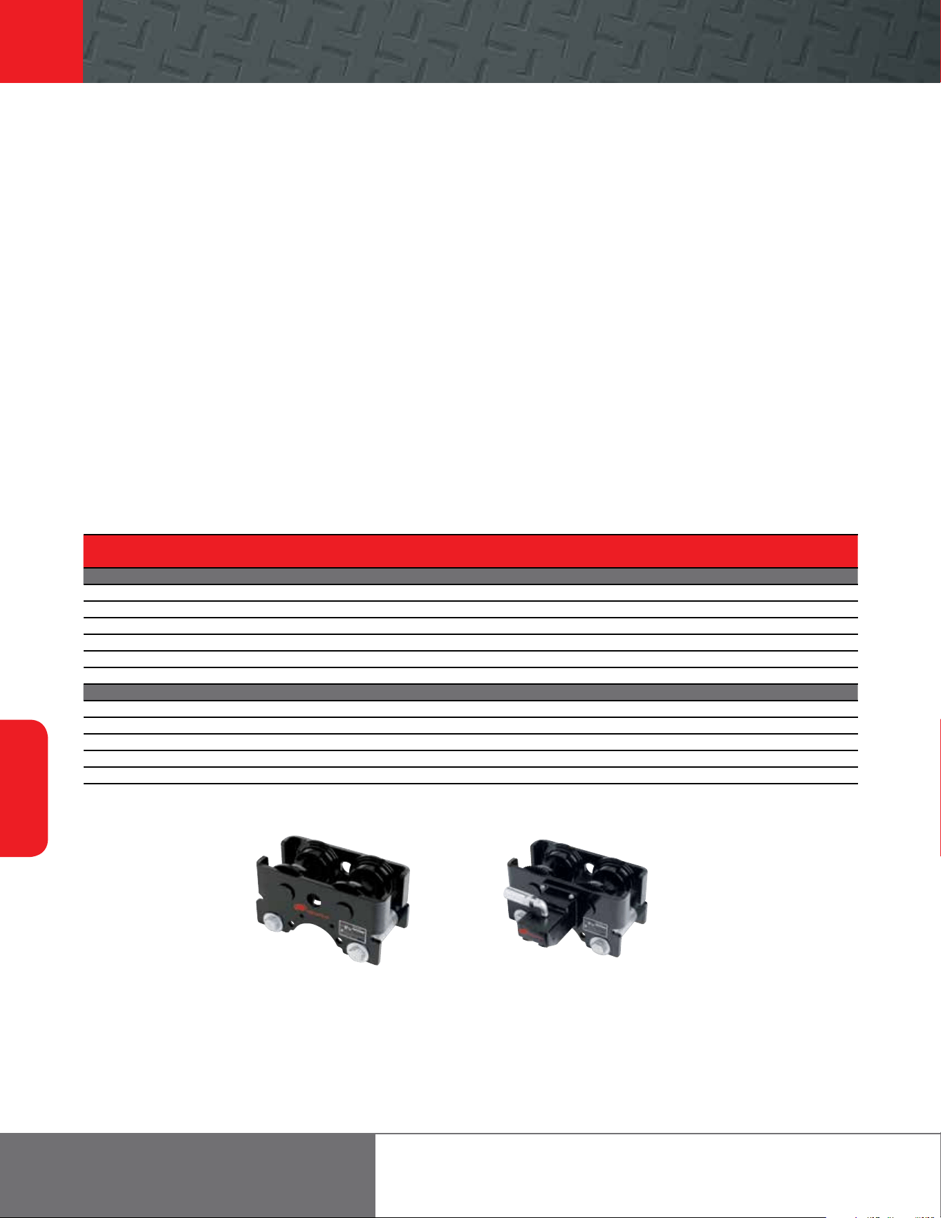
40
Trolleys and
Beam Clamps
866-207-6923
TIR Series
0.25 to 6 metric ton capacities
TIR6600 plain trolley TIR6600 motorized trolley
• Meets ANSI B30.16 for hoisting requirements — 5:1 minimum
safety factor
• All-steel construction
• Universal wheels fit both flat and tapered beam flanges
• Rail sweeps are integral with the side plates
• Cast-iron wheels roll easily on permanently greased
sealed bearings
• 7’ pendent control or 8’ hand chain length — other lengths available
• Tight turning radius
• Standard 3-ton trolley fits 3.25” – 6” flange width, 6-ton fits
4.25” – 7.25”
• Modular trolley frame allows hook-on, plain rigid, geared,
and motorized configurations in the field
• Motorized trolley has automatic disc brake
• Low air consumption at only 35 scfm on motorized versions
Options
• Solid bronze wheels for maximum spark resistance
• Wide flange kit for 3-ton fits 6” – 12”
• Hook-on adapters
• Lug adapters for rigid-mounting Ingersoll Rand hoist
Features
TIR Series trolleys are supplied as standard equipment for MLK Series, and HLK Series hoists when specified.
The TIR trolley may also be used as a hook-on trolley with any hoist.
TIR Series Trolley Specifications
Trolley Type Capacity Min. Curve Radius Standard Flange Adj. Hand Chain/Pendent Drop Trolley Weight
lb metric tons in in lb
TIR6600 TROLLEy SERIES
Plain hook-on 550 - 6,600 0.25 - 3 42 3.3 - 6 N/A
31
Plain rigid 550 - 6,600 0.25 - 3 42 3.3 - 6 N/A
34
Geared hook-on 550 - 6,600 0.25 - 3 42 3.3 - 6 7
34
Geared rigid 550 - 6,600 0.25 - 3 42 3.3 - 6 7
37
Motorized 550 - 6,600 0.25 - 3 42 3.3 - 6 7
35
Plain 550 - 6,600 0.25 - 3 42 3.3 - 6 N/A
25
TIR132 TROLLEy SERIES
Plain hook-on 9,900 - 13,200 4.5 - 6 60 4.3 - 7.3 N/A
154
Plain rigid 9,900 - 13,200 4.5 - 6 60 4.3 - 7.3 N/A
150
Geared hook-on 9,900 - 13,200 4.5 - 6 60 4.3 - 7.3 7
157
Geared rigid 9,900 - 13,200 4.5 - 6 60 4.3 - 7.3 7
153
Motorized 9,900 - 13,200 4.5 - 6 60 4.3 - 7.3 7
155
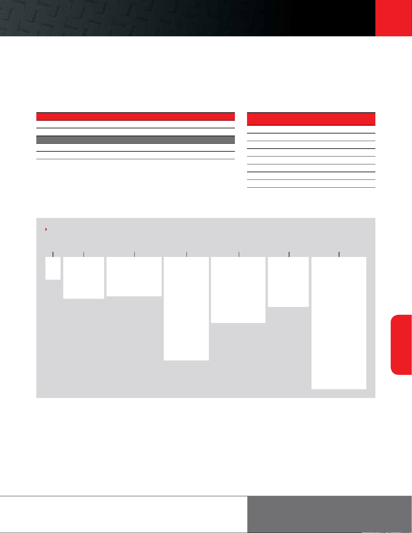
Footer 41
41
Trolleys and
Beam Clamps
ingersollrandproducts.com/liing
TIR Series
0.25 to 6 metric ton capacities
TIR 6600 S - G 08 D P
Series
TIR
RT
Chain or pendent length
07 = 7 (standard
for pendent)
08 = 8 (standard
for hand chain)
XX = Specify length
in feet
00 = No pendent or
hand chain or a
plain trolley
HOW TO ORDER
Example: TIR6600S-G08DP
Type
P = Plain trolley
(1)
G = Hand chain gear
driven
0 = Vane motor air
driven, no
pendent
2 = Vane motor air
driven, 1 motor
pendent
(2)
3 = Vane motor air
driven, 2 motor
pendent
(2)
4 = Vane motor air
driven, 3 motor
pendent
(2)
Flange width (in)
A = Fits 3 ton
(3.3 - 6)
6 ton
(4.3 - 7.3)
D = Fits 3 ton
(6 - 12)
6 ton (N/A)
Suspension type
P = Plain (without lug)
(1)
A = 7790 plain, no
adapter
E = 7700 0.25-1 ton to
TIR6600 adapter
J = HLK 1 and 1.5 ton
lug adapter
(1)
K = HLK 2 and 3 ton
lug adapter
(1)
H = Hook adapter
(3 and ton TIR6600
only)
M = MLK to TIR6600
lug adapter
(TIR6600 only)
R = 7700 0.25-1 ton to
RT adapter
T = RT rigid lug
adapter
Motorized Trolley Specifications
Hoist Capacity Trolley Speed On Beam*
lb metric tons fpm
550 0.25 95
1,100 0.50 93
2,200 1 88
3,300 1.50 84
4,400 2 80
6,600 3 71
9,900 4.50 60
12,000 6 45
Note:
*Beam in good condition.
TIR Series Flange and Adapters Kits
Flange Kits Flange Width (in) Part Number
Standard 3.3 – 6 49558
Wide 6 – 12 49559
Adapter Kits Option Code Part Number
Hook-on H TIR-426
90° Trolley Adapter* 43111
* Used to mount any 7790 Series hoist parallel to suspension beam. Adapter increases headroom dimension by
1.625 inches.
NOTE:
(1) Required to install TIR6600 trolley on HLK1-3t hoist
with top lug manufactured July 1995 or before, or to
convert any hook mount to rigid trolley.
(2) Standard pendents are full flow for the TIR trolley. Pilot
and full flow for the second and third function. If control
length exceeds 20 , quick exhaust valves are required.
See table and associated pricing, as with the MTK tractor.
Capacity
6600 = 6,600 lb/
3 ton
132 = Standard
010 = 2,200 lb/
1 ton
Standard or S*COR*E
S = Standard cast
iron wheels
B = Standard bronze
wheels for S*COR*E
features
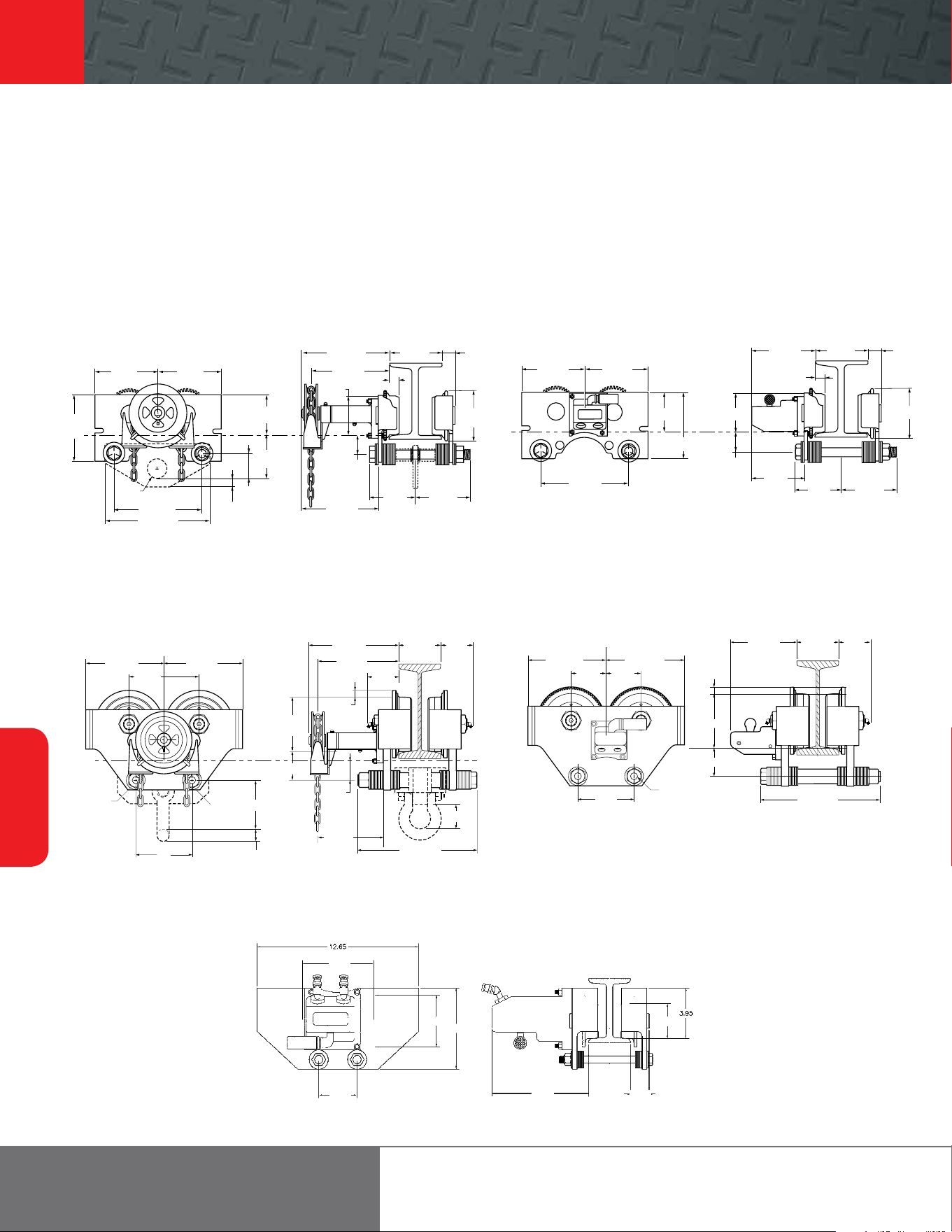
42
Trolleys and
Beam Clamps
866-207-6923
TIR Series
0.25 to 6 metric ton capacities
TIR6600 plain, geared, and
lug-mounted trolley
TIR6600 motorized trolley
TIR132 plain, geared, and
hook-mounted trolley
TIR132 motorized trolley
RT010 motorized trolley
TIR6600, TIR132, and RT010 dimensions
7-3/8” 7-3/8”
7-11/16”
4-1/2”
Treadline
ø2-1/4”
10-1/4”
12-9/32”
1-1/16”
2-7/8”
5-1/8”
10-3/16” 1-9/16”
Flange
9-1/16”
1-5/32”
4-1/2”
5-3/4”
6-7/16”5-3/8”
2-1/4”
7-3/8” 7-3/8”
10-1/4”
4-1/2”
7-11/16”
Treadline
4-1/2”
2-1/4”
7-15/32”
1-5/32”
67-1/4”
1-9/16”Flange
5-3/4”
5-3/8” 6-7/16”
9-11/16” 9-11/16”
8-3/4”
Holes for
1-1/8” Ø bolts
1-1/8”
Ø bolt
7-1/4”
1-1/2”
10-3/16”
4-1/4”–
7-1/4”
flange
4-3/8”
9-1/16”
4-3/8”
13/16”
7” Ø
3-5/8”
2-1/4”
8-31/32”
2-1/16”
14-13/16”
7”
9-11/16” 9-11/16”
4-3/8” 4-3/8”
7”
1-1/8” Ø bolt
Treadline
13/16”
7” Ø
3-5/8”
8-3/16”
4-1/4”–
7-1/4”
flange
4-3/8”
14-13/16”
6.35”
7.55”
1.45”
2.75” Ø
3.00”
5.55”
4.05” Ø
6.35”
7.55”
1.45”
2.75” Ø
3.00”
5.55”
4.05” Ø
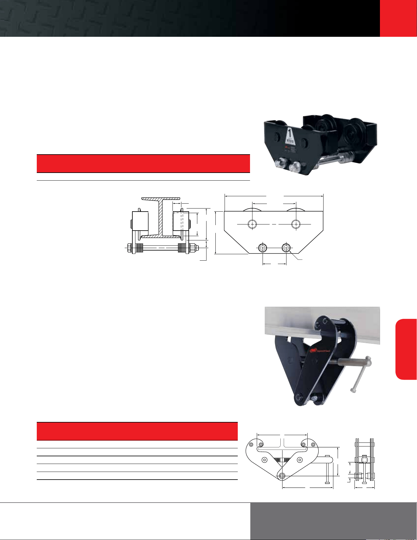
Footer 43
43
Trolleys and
Beam Clamps
ingersollrandproducts.com/liing
RT Series trolley
1 metric ton capacity
Plain and rigid
Cousin to the PT Series trolley, the twin suspension sha RT Series trolley oers a rigid
connection for the MLK, MLKS, and MLKR Series of air chain hoists. Like the PT Series,
the RT Series uses universal tread wheels for use on flat or tapered flange beams.
RT010 Series Trolley Specifications
Trolley Capacity Fits Beam Minimum Turning
Part metric Flange Width Radius
Number tons in in
RT010 0.25 - 1 2.7 - 6 36
Wheels have universal tread for use on flat or tapered beams.
BC Series
1 to 10 metric ton capacities
Beam clamp features
Ingersoll Rand beam clamps provide temporary or permanent mounting options for
a wide range of tapered or flat beams. These units have been designed and verified —
by actual pull testing — to achieve a minimum design factor of 5:1 for vertical liing
with a powered or manual hoist, which meets ASME B30.16.
These beam clamps oer quick and simple one-handed installation without requiring any tools.
Units accommodate hook-mounted hoist or load blocks with minimal loss of headroom. The
clamp jaws are designed to reduce beam stress by applying the load inside of the flange edge.
• Quick installation by hand and with no required tools
• Low headroom design adjusts to fit a wide range of flat or tapered beams
• Meets ASME B30.16 for use with powered or manual hoists
• Each unit is serialized and supplied with a test certificate and manual
• Metric rated for vertical liing at 2,200 lb per ton
BC Series Beam Clamp Specifications and Dimensions
Capacity Beam Width
Weight metric A B C D E F
Model lb tons in in in in in in
BC-1 9.9 1 3 - 10.2 3.1 9.6 4 - 5.9 1.2 0.9
BC-2 11 2 3 - 10.2 3.5 9.6 4. - 5.9 1.2 0.9
BC-3 23.1 3 3.2 - 13.9 4.7 11.2 6 - 8.9 2 0.9
BC-5 24.2 5 3.2 - 13.9 4.9 11.2 6 - 8.9 1.9 1.1
BC-10 35.2 10 3.5 - 14.4 5.7 11.3 6.9 - 9.3 2.2 1.6
1-1/32”
4-1/16”
2-1/4”
5-3/8”
1-5/8”
12-5/8”
5-9/16”
3”
5/8” Dia. bolt
A
C
F
D
E
B
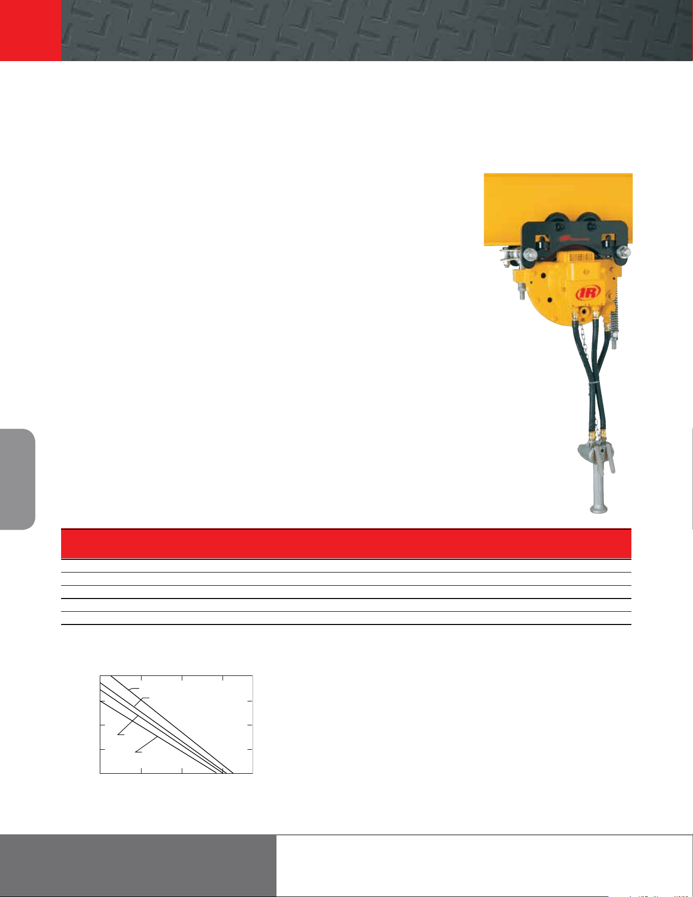
44
Portable
Air Winches
866-207-6923
MTK Series
6 metric ton towing capacity
Features
MTK Series tractors require less air, making them less expensive to operate. They’re designed for use
with any hoist, or even alone to push, pull, or position loads on beams.
• Up to 6 metric ton towing capacity
• Interchangeability with MLK Series and HLK Series
parts
• Balanced gear package and air motor provide speeds
from slow creep to 165 fpm
• Million-cycle performance tested air motor with
spring-loaded vanes provides instant starting and slow
speed control
• Heat-treated planetary gearing assures longer life and
reduced maintenance
• Self-adjusting, spring-applied, non-asbestos disc brake
is air-released for smooth starts and stops
• Drive tire is made from extremely durable
polyurethane material with a temperature rating of
185° F for excellent adjustable gripping characteristics
• Tight turning radius of 30”
• Universal solid cast-iron wheels fit both flat
and tapered beams
• Wheels can be greased for longer life
• Standard tractor fits 2.7” – 6.3” beam flange widths
• Roller guides made from high alloy steel keep tractor
running smoothly
• Tractor operates with a full-flow pendent, enhancing
load-spotting control
• Standard 7’ pendent length
• Tow bar included with tractor
Options
• Free wheel kit that permits moving of tractor without
supplying air; attaches directly to tractor without
modification
• Wide flange kit fits 6.27 – 12” beam flange widths
• Pull chain operation
• Bronze wheels for spark-resistant applications
• Gasket repair and manual brake release kits
• Drawbar hitch kit
• External brake release kit relieves auto disc brake
without running tractor
MTK Series Tractor Specifications*
Drawbar Capacity Max Pendent Turning Beam Flange Width
Pull Flat, Dry Good Curved, Slick, Poor Speed Length Radius Standard Optional
lb metric tons metric tons fpm in in in
0 0 0 165 7 30 2.7 - 6.3 6.3 - 12
100 1.50 0.75 117 7 30 2.7 - 6.3 6.3 - 12
200 3 1.50 86 7 30 2.7 - 6.3 6.3 - 12
300 4.25 2.25 57 7 30 2.7 - 6.3 6.3 - 12
400 6 3 21 7 30 2.7 - 6.3 6.3 - 12
*At 90 psi inlet pressure. Average air consumption is 35 scfm; range is 25 to 45 scfm, depending on load and air pressure.
Draw Bar Load vs. Tractor Speed
400 (180)
300 (135)
200 (90)
100 (45)
0
0
50 (15) 100 (30) 150 (45) 180 (55)
Tractor speed fpm (m/min)
Drawbar pull lb (kg)
90 psig
80 psig
70 psig
60 psig
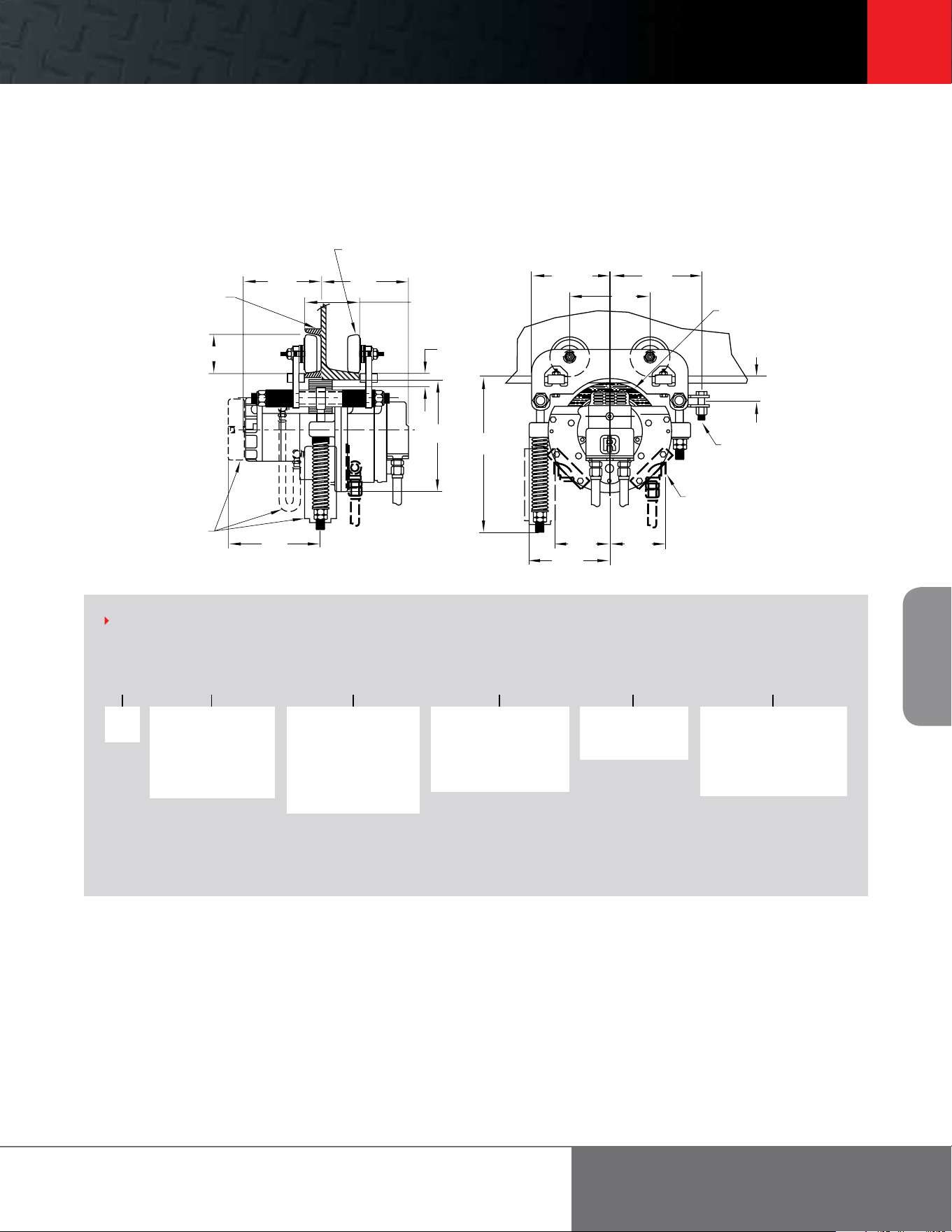
Footer 45
45
Portable
Air Winches
ingersollrandproducts.com/liing
MTK S 3 07 A M
Series
MTK
Chain or pendent length
07 = 7 (standard)
XX = Specify length in feet
00 = No pendent hose or
pull chain
HOW TO ORDER
Specify complete model number as shown. This model code includes: Series, Standard or S*COR*E, type of Trolley, length of chain or pendent drop, flange width, and
options Some accessories may be ordered by specifying them as an option code or by ordering separately by part number. See the Accessories and Options charts above.
Example: MTKS-307AM
Standard or S*COR*E
S = Standard cast
iron wheels
B = Standard bronze
wheels for S*COR*E
features
(1) Specify when used in combination with hoist on the same order.
Specify multiple pendent control function on the hoist only.
(2) Do not specify if tractor is ordered with a hoist.
Type of control/trolley
0 = No pendent
(1)
1 = Pull chain
2 = Single motor pendent
(1)
3 = Two motor pendent
(2)
4 = Three motor pendent
Flange width (in)
A = Fits 2.66 - 6.25
D = Fits 6.26 - 12.00
Options
E = External brake release kit
F = Free wheel
M = Manual brake release
P = Piped away exhaust
Bottom of
wheel
2
Universal wheels for flat or tapered
Flange-A 2-21/32 to 6-1/4, Flange-D 6-17/64 to 12”
4 “S” beam min
2-21/32” flange
6-5/16”
7-1/8”
3-1/4”
2-21/32 to 6-1/4” std.
1-1/16” clearance
Optional free
wheeling kit
7-1/2”
9-1/8”
6-13/32”
7-3/8”
6-5/8”
8” Polyurethane wheel
1/2” Bolt for draw bar
3/8” NPT inlet if used with
single function pendent.
May be mounted on either side.
4-7/16” 4-7/16”
6-9/16”
12-13/16”
2”
MTK Series
6 metric ton towing capacity
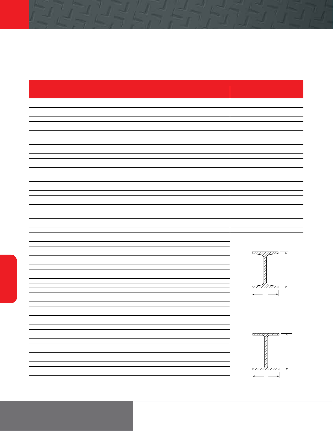
46
Trolleys and
Beam Clamps
866-207-6923
Wide Flange American Standard
H W Weight per H W Weight per H W Weight per H W Weight per
in in lb in in lb in in lb in in lb
6 3.94 8.5 10 10.117 66.0 16* 6.985 36 4 2.663 7.7
6* 4.0 9.0 10* 10.130 68.0 16 7.0 40 4 2.796 9.5
6 4.0 12.0 10 10.170 72.0 16* 6.995 40 5 3.004 10.0
6* 4.0 12.0 10 10.190 77.0 16 7.039 45 5 3.284 14.75
6 4.030 16.0 10* 10.190 77.0 16* 7.035 45 6 3.332 12.5
6* 4.030 16.0 10* 10.625 88.0 16 7.073 50 6 3.565 17.25
6* 5.990 15.0 10 10.275 89.0 16* 7.07 50 7 3.662 15.3
6 5.995 15.5 10 10.340 100.0 16* 7.12 57 7 3.860 20.0
6 6.020 20.0 10* 10.340 100.0 16 8.464 58 8 4.001 18.4
6 6.018 20.0 10 10.415 112.0 16* 10.235 67 8 4.171 23.0
6 6.080 25.0 10* 10.415 112.0 16* 10.295 77 10 4.661 25.4
6* 6.080 25.0 12 3.968 14.0 16* 10.365 89 10 4.944 35.0
8 3.940 10.0 12* 3.970 14.0 16* 10.425 100 12 5.0 31.8
8* 3.940 10.0 12* 3.990 16.0 16 11.502 88 12 5.078 35.0
8 4.0 13.0 12 4.0 16.5 16 11.5 96 12 5.252 40.8
8* 4.0 13.0 12 4.005 19.0 18 6.0 35 12 5,477 50.0
8 4.015 15.0 12* 4.007 19.0 18* 6.0 35 15 5.501 42.9
8* 4.015 15.0 12 4.030 22.0 18 6.015 40 15 5.640 50.0
8 5.250 17.0 12* 4.030 22.0 18* 6.015 40 18 6.001 54.7
8* 5.250 18.0 12* 6.490 26.0 18* 6.060 46 18 6.251 70.0
8 5.268 20.0 12 6.497 27.0 18 7.477 45 20 6.25 65.4
8* 5.270 21.0 12* 6.520 30.0 18 7.5 50 20 6.385 75.0
8 6.495 24.0 12 6.525 31.0 18* 7.5 50 20 7.060 86.0
8* 6.5 24.0 12* 6.560 35.0 18 7.532 55 20 7.200 96.0
8 6.535 28.0 12 6.565 36.0 18* 7.530 55 24 7.001 79.9
8* 6.535 28.0 12 8.0 40.0 18 7.558 60 24 7.125 90.0
8 7.995 31.0 12* 8.005 40.0 18* 7.555 60 24 7.245 100.0
8* 7.995 31.0 12 8.042 45.0 18* 7.635 71 24 7.875 105.9
8 8.020 35.0 12* 8.045 45.0 18 8.715 64 24 8.050 121.0
8* 8.020 35.0 12 8.077 50.0 18 8.75 70
8 8.070 40.0 12* 8.080 50.0 18 8.787 77
8* 8.070 40.0 12 10.0 53.0 18* 11.035 76
8 8.110 48.0 12* 9.995 53.0 18* 11.090 86
8* 8.110 48.0 12 10.014 58.0 18* 11.145 97
8 8.220 58.0 12* 10.010 58.0 18* 11.200 106
8* 8.220 58.0 14 5.0 22.0 18* 11.265 119
8 8.280 67.0 14* 5.0 22.0 18 11.75 96
8 8.280 67.0 14 5.025 26.0 21 6.5 44
10 3.950 11.5 14* 5.025 26.0 21* 6.5 44
10* 3.960 12.0 14 6.730 30.0 21* 6.530 50
10 4.0 15.0 14* 6.730 30.0 21* 6.555 57
10* 4.0 15.0 14 6.75 34.0 21 8.215 55
10 4.010 17.0 14* 6.745 34.0 21 8.240 62
10* 4.010 17.0 14 6.770 38.0 21* 8.240 62
10 4.020 19.0 14* 6.770 38.0 21 8.270 68
10* 4.020 19.0 14 8.0 43.0 21* 8.270 68
10 5.75 21.0 14* 7.995 43.0 21 8.295 73
10* 5.75 22.0 14 8.031 48.0 21 8.295 73
10 5.762 25.0 14* 8.030 48.0 21* 8.355 83
10* 5.770 26.0 14 8.062 53.0 21* 8.420 93
10 5.799 29.0 14* 8.060 53.0 21 8.962 82
10* 5.810 30.0 14 10.0 61.0 24 7.005 55
10 7.960 33.0 14* 9.995 61.0 24* 7.005 55
10* 7.960 33.0 14 10.035 68.0 24* 7.040 62
10 7.985 39.0 14 10.035 68.0 24 8.961 68
10* 7.985 39.0 14 10.072 74.0 24* 8.965 68
10 8.020 45.0 14* 10.070 74.0 24 8.965 76
10* 8.020 45.0 14 12.0 78.0 24* 8.990 76
10 10.0 49.0 14 14.5 87.0 24 9.015 84
10* 10.0 49.0 14* 10.130 82.0 24* 9.020 84
10 10.030 54.0 16 5.5 26.0 24 9.065 94
10* 10.030 54.0 16 5.525 31.0 24* 9.065 94
10 10.080 60.0 16* 5.625 31.0 – – –
10* 10.080 60.0 16 6.692 36.0 – – –
I-beam specifications
The following table shows the standard size (H) , flange widths (W), and weights for both American, Standard I-beams, and Wide Flange H-beams.
I-beams designated with an asterisk (*) denote New Series applications which conform to ASTM A6 standards, eective September 1, 1978.
American Standard
H
(Nom.)
W
Tapered “ S ” Beam
Wide Flange
H
(Nom.)
W
Tapered “ S ” Beam
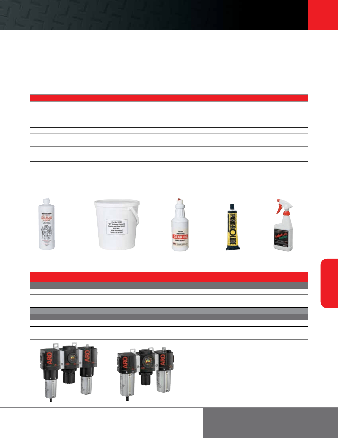
Footer 47
47
Trolleys and
Beam Clamps
ingersollrandproducts.com/liing
Lubricants
Part No. Amount Product Description Where Used
29665 1 qt (0.9 L)
Detergent-free spindle oil with viscosity of 155-165 S.U.S. at 100*F
and aniline point of 217*F.
In airline lubricator to provide lubrication to hoist air motor.
33153 5 lb (2.3 kg)
EP (extreme pressure) bearing and gear grease, NLGI No. 1 with
viscosity of 750 S.U.S. at 100*F.
Pocket wheel, sheave block
50P 1 pt (0.5 L) Class II lubricant, #50 Hoist and winches
40164 1 qt (0.9 L) Gear oil Hoist gearing
50G 1 gal (3.8 L) Class II lubricant, #50 Hoist and winches
62 1 Gal 1 gal (3.8 L) Class II #62 oil Hoist and winch gear boxes
36460 4 oz (118 ml)
Stringy lubricant for rubber seals
Triple protection, USDA approved lubricant
Extreme pressure formula and corrosion inhibitors, penetrating oils.
“O” rings
Load chain or wherever penetrating lubricating oils are used
Lubri-Link Green 16 oz spray bottle
Stringy lubricant for rubber seals
Triple protection, USDA approved lubricant
Extreme pressure formula and corrosion inhibitors, penetrating oils.
“O” rings
Load chain or wherever penetrating lubricating oils are used
LLG-5 5 gal bulk container
Stringy lubricant for rubber seals
Triple protection, USDA approved lubricant
Extreme pressure formula and corrosion inhibitors, penetrating oils.
“O” rings
Load chain or wherever penetrating lubricating oils are used
Filters - Regulators - Lubricators
Size (in) Flow Rate Adj. Pressure Bowl Height x Width
Part No.
NPTF scfm Range psig Capacity (in)
TRIO UNITS: FILTERS, REGULATORS, LUBRICATORS
C38341-810 1/2 150 5-250 4 oz 6 x 8.7
C38451-810 3/4 200 5-250 4 oz 8.6 x 11.1
C38461-810 1 215 5-250 4 oz 8.6 x 11.1
Part No. COMPONENTS
TRIO # FILTER REGULATOR LUBRICATOR
C38341-810 1/2 F35341-410 R37341-600 L36341-110
C38451-810 3/4 F35451-410 R37451-600 L36451-110
C38461-810 1 F35461-410 R37461-600 L36461-110
C38451-810 C38341-810
These approved lubricants are suggested for either routine preventive maintenance procedures or for total hoist overhaul.
3315329665 40164 36460 Lubri-Link Green
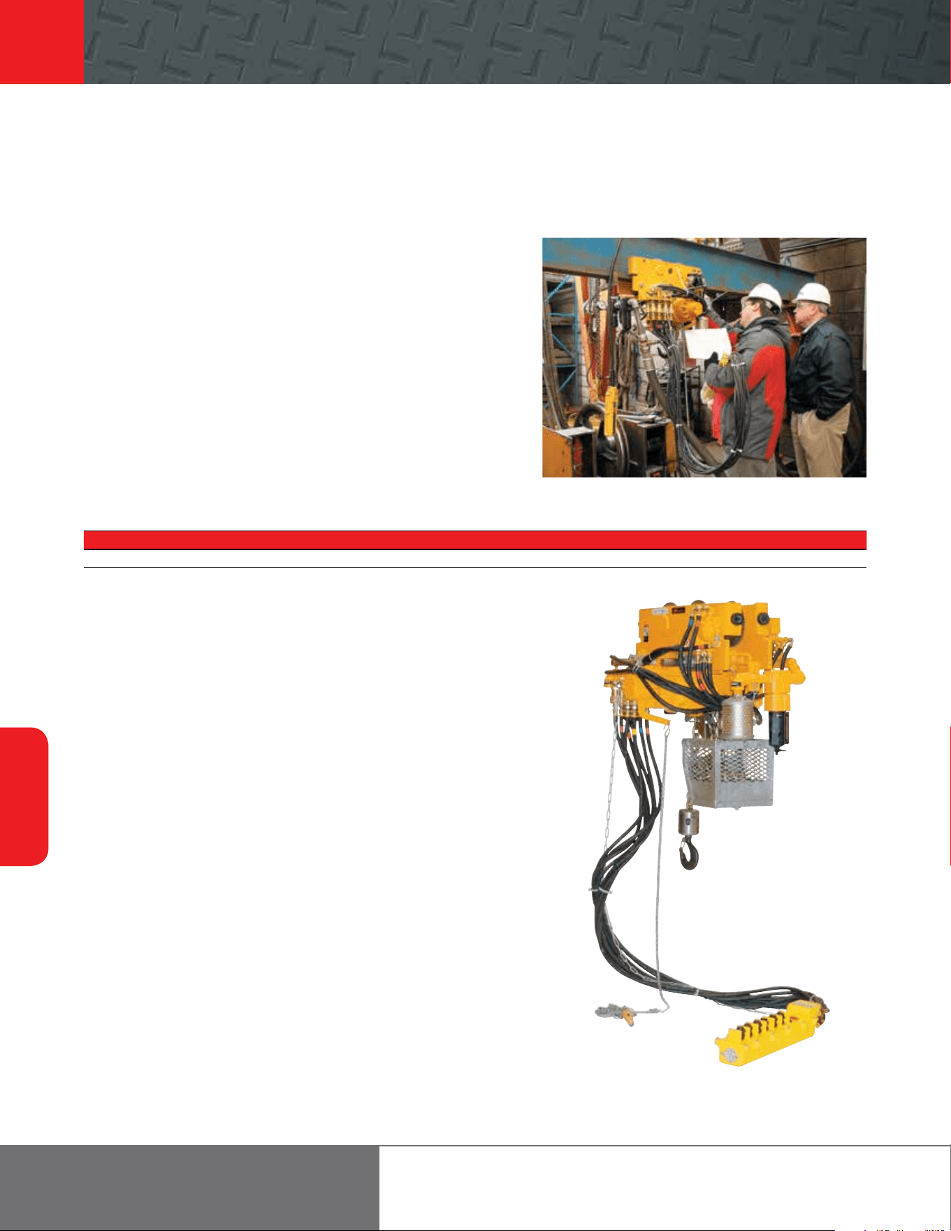
48
Trolleys and
Beam Clamps
866-207-6923
Material Handling Solutions
Case study
Ingersoll Rand routinely provides custom solutions for liing and
pulling applications all over the world. Please contact an authorized
Ingersoll Rand distributor or representative for assistance with your
application’s requirements.
Model
HL2000K/04014E
Application
Nuclear weapon handling hoist and motorized trolley system
Solution
Customer required hoists to be built to ASME NUM-1, Rules for Construction of Cranes,
Monorails, and Hoists, a design standard for hoists and cranes used in nuclear facilities.
Hoists are to be used for the assembly and maintenance of nuclear weapons.
Options
• Special quick disconnect pendent manifold
• Positive sealed motor and gearbox — zero tolerance for leakage for
“clean room” environment
• Pendent designed to survive a 150 psi overpressure condition
• Custom chain container with drain plug
• Unpainted bare steel bottom hook
• Overload limiter on hoist
• Ecology air preparation package for hoist and trolley
• Custom operation and maintenance manuals and special documentation
• Special customer defined NDE, sound, and load testing requirements
• Long-term storage packaging requirements
• Lightning arrest modifications
Product Specifications
Model Capacity Design Factor Headroom Liing and Lowering Speed Trolley Travel Speed
HL2000K/04014E 2,000 lb (909 kg) 10:1 22 in (558.8 mm) maximum Not to exceed 10 fpm (3 m/min) Not to exceed 16 fpm (4.9 m/min)
HLK2000K/04014E
Footer 49
49
ingersollrandproducts.com/liing
Notes

866-207-6923
Limited Warranty
Industrial Liing Equipment Limited Warranty
Ingersoll Rand Company (IR) warrants to the original user its industrial liing equipment (Hoists) to be free of
defects in material and workmanship for a period one year from the date of purchase. Ingersoll Rand will repair,
without cost, any Hoist found to be defective, including parts and labor charges, or at its option, will replace
such Hoist or refund the purchase price less a reasonable allowance for depreciation, in exchange for the hoist.
Repairs or replacements are warranted for the remainder of the original warranty period.
If any Hoist proves defective within its original one year warranty period, it should be returned to an
appropriate Ingersoll Rand Service Distributor, transportation prepaid with proof of purchase or warranty card.
This warranty does not apply to Hoist that Ingersoll Rand has determined to have been misused or abused,
improperly maintained by the purchaser, or where the malfunction or defect can be attributed to the use of non-
genuine Ingersoll Rand parts.
Ingersoll Rand makes no other warranty, and all implied warranties including any warranty of merchantability or
fitness for a particular purpose are limited to the duration of the expressed warranty period as set for the above.
Ingersoll Rand’s maximum liability is limited to the purchase price of the Hoist and in no event shall Ingersoll
Rand be liable for any consequential, indirect, or special damages of any nature arising from the sale or use of
the Hoist, whether based on contract, tort, or otherwise.
Note: Some states do not allow limitations on incidental or consequential damages so that the above limitations
may not apply to you. This warranty gives you specific legal rights and you may also have other rights that may
vary from state to state.
Product, Parts, Maintenance, Operation, and Safety manuals can be
downloaded from irtechpubs.com

Footer 51
51
Accessories Trolleys and Beam
Clamps
Portable
Air Winches
Electric Chain
Hoists
Air Chain
Hoists
Manual Chain
Hoists
ingersollrandproducts.com/liing
© 2013 Ingersoll Rand IRITS-0709-066 / 05132013
Ingersoll Rand (NYSE:IR) advances the quality of life by creating and sustaining safe, comfortable and ecient environments.
Our people and our family of brands—including Club Car®, Ingersoll Rand®, Schlage®, Thermo King® and Trane® —work
together to enhance the quality and comfort of air in homes and buildings; transport and protect food and perishables;
secure homes and commercial properties; and increase industrial productivity and eciency. Ingersoll Rand products range
from complete compressed air systems, tools and pumps to material handling systems. The diverse and innovative products,
services and solutions enhance our customers’ energy eciency, productivity and operations. We are a $14 billion global
business committed to a world of sustainable progress and enduring results. For more information, visit ingersollrand.com.
Ingersoll Rand, IR and the IR logo are trademarks of Ingersoll Rand, its subsidiaries and/or aliates. All other trademarks are the property of their respective owners.
WARNING: This equipment is not designed for transporting people or liing loads above people. It is the user’s responsibility to determine the suitability of
this product for any particular use and to check compliance with applicable regulations. Before installation, see maintenance and operations manual for
additional warnings and precautions
Nothing contained on these pages is intended to extend any warranty or representation, expressed or implied, regarding the product described herein.
Any such warranties or other terms and conditions of sale of products shall be in accordance with Ingersoll Rand’s standard terms and conditions of sale
for such products, which are available upon request.
Product improvement is a continuing goal at Ingersoll Rand. Designs and specifications are subject to change without notice or obligation.
www.ingersollrandproducts.com
Distributed by:
We are committed to using environmentally conscious print practices.