
802.15.4 RADIO MODULE (TA-ICX-499-154RAD) User Manual
1
Contents
1. Radio Module Overview................................................................................................................................................ 2
2. STM32WB55 Microcontroller Overview .............................................................................................................. 2
3. Radio Module Images .................................................................................................................................................... 2
4. Block Diagram of 802.15.4 radio board ............................................................................................................... 3
5. 802.15.4 Radio Capabilities of STM32WB55 ...................................................................................................... 3
6. Security Features ............................................................................................................................................................. 4
7. Installation Procedure .................................................................................................................................................. 4
8. Certifications ..................................................................................................................................................................... 4
8.1 FCC Compliance ............................................................................................................................................................... 4
8.2 FCC RF Exposure Compliance .................................................................................................................................... 5
8.3 ISED Compliance ............................................................................................................................................................. 5
8.4 ISED RF Exposure Compliance .................................................................................................................................. 6
9. Datasheet links ................................................................................................................................................................. 7
10. Revision History ............................................................................................................................................................... 7
802.15.4 RADIO MODULE (TA-ICX-499-154RAD) User Manual
2
1. Radio Module Overview
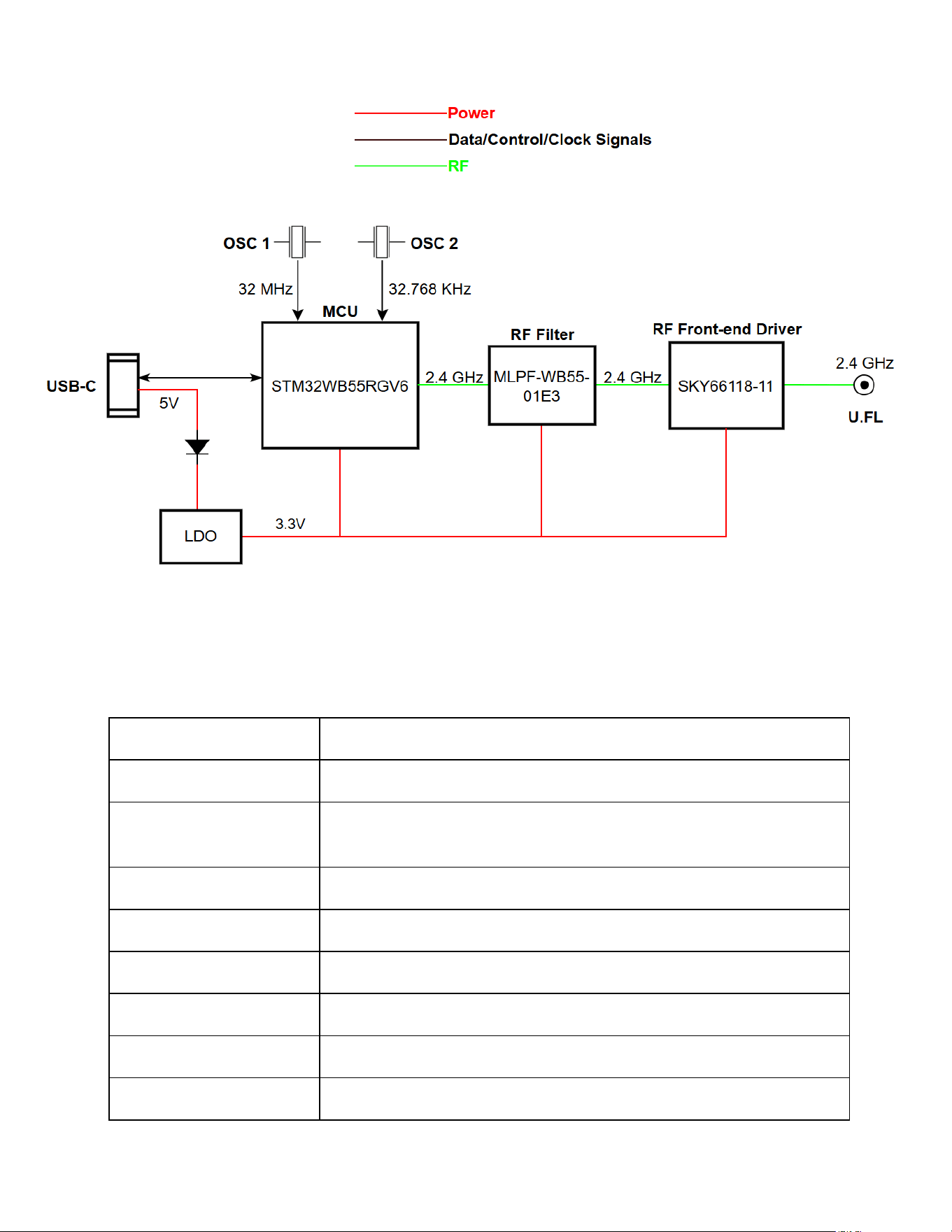
Ingersoll Rand 802.15.4 external radio module is designed for use with only Ingersoll rand products
and is recommended to be installed by Ingersoll Rand authorized engineers/distributers. This radio
module is designed around the STM32WB55RGV6 microcontroller, a dual-core wireless MCU from
STMicroelectronics that integrates an Arm® Cortex®-M4 core for application processing and an
Arm® Cortex®-M0+ core dedicated to wireless protocol stack execution. The module is optimized
for low-power wireless communication in the 2.4 GHz ISM band, supporting Bluetooth Low Energy
(BLE) and 802.15.4 protocols.
Power Architecture:
• Power Input: The module receives power via a USB-C connector, supplying 5V DC.
• Voltage Regulation: A Low Dropout Regulator (LDO) converts the 5V input to 3.3V, which
powers all active components including the MCU and RF circuitry.
Clock Sources
• The STM32WB55 is supported by two precision oscillators:
OSC 1 (32 MHz): Primary high-speed clock for MCU and RF operations.
OSC 2 (32.768 KHz): Low-speed clock for real-time clock (RTC) and low-power modes.
RF Signal Chain
• RF Filtering: The MCU’s RF output is routed through a 2.4 GHz RF filter (MLPF-WB55-
01E3) to suppress harmonics and improve signal integrity.
• RF Amplification: The filtered signal is then passed to a 2.4 GHz RF front-end driver
(SKY66118-11), which boosts the signal for transmission.
• Antenna Interface: The amplified RF signal is output via a U.FL connector, allowing
connection to an external antenna for optimal wireless performance.
2. STM32WB55 Microcontroller Overview
The STM32WB55 is a dual-core ultra-low-power microcontroller supporting multiple
wireless protocols, including Bluetooth LE 5.4, IEEE 802.15.4, Zigbee, Thread, and Matter. It
has a dual-core architecture: Application core (Arm Cortex-M4 @ 64 MHz with FPU, DSP, MPU)
and Network core (Arm Cortex-M0+ @ 32 MHz dedicated to radio stack).
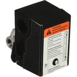
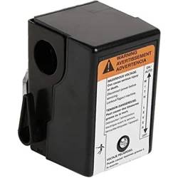
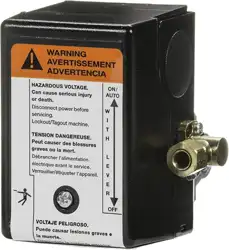
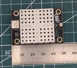
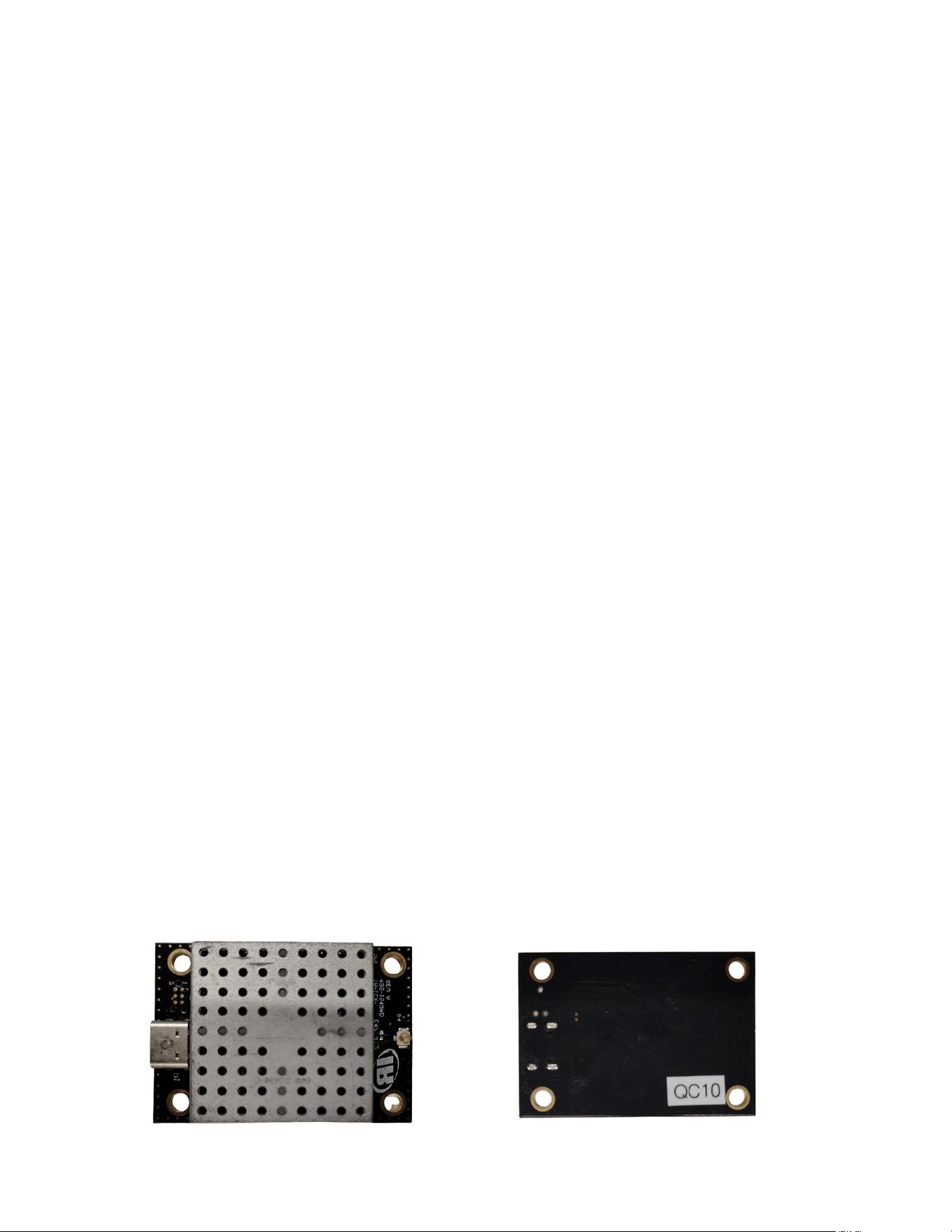
3. Radio Module Images
802.15.4 RADIO MODULE (TA-ICX-499-154RAD) User Manual
3
4. Block Diagram of 802.15.4 radio board
5. 802.15.4 Radio Capabilities of STM32WB55
• Standard Compliance: IEEE 802.15.4-2011 PHY and MAC
• Frequency Band: 2.4 GHz ISM
• Integrated Balun and External PA Support
• OTA Firmware Updates for 802.15.4 Stack
Category
Details
Standard Compliance
IEEE 802.15.4-2011 PHY & MAC (Zigbee® 3.0, Thread® 1.3)
Controller Core
Dual-core: Cortex-M4 @ 64 MHz (application) + Cortex-M0+ @ 32
MHz (radio stack)
Frequency Band
2.4 GHz ISM (2400–2483.5 MHz)
Channel Plan
15 channels (11–25), 5 MHz spacing, 2 MHz occupied BW
Modulation
O-QPSK (DSSS)
Data Rate
250 kbps
Symbol Rate
62.5 ksymbols/s
TX Power Range
-20 dBm to +6 dBm (1 dB steps)
802.15.4 RADIO MODULE (TA-ICX-499-154RAD) User Manual
4
Category
Details
RX Sensitivity
-100 dBm
Coexistence
BLE + 802.15.4 dynamic time-sharing (RTSM)
Security
AES-128/256 hardware accelerator, CCM mode, PKA, TRNG
PHY Timing
CSMA-CA, ED, LQI supported
Supply Voltage
1.71 V – 3.6 V
OTA Update
Supported for BLE and 802.15.4 stacks
6. Security Features
• AES Encryption: Up to 256-bit for 802.15.4 MAC layer
• Public Key Accelerator (PKA): RSA, ECC, Diffie-Hellman
• True Random Number Generator (RNG)
• Secure Firmware Installation (SFI)
• Customer Key Storage (CKS)
7. Installation Procedure
• The product is designed to be installed into the Ingersoll Rand products only and must be
installed by an authorised engineer/supplier.
• Connect the required antenna type to the module on the U.FL connector.
• Use only approved or equivalent antennas
• Close the enclosure of the radio module.
• Install the module into/onto the required Ingersoll Rand product.
• Connect the USB cable to the Type-C USB connector on the module.
• Connect the other side of the USB to the product to which the module is being installed.
• Any modification to antennas may result in violation of compliance certification.
8. Certifications
8.1 FCC Compliance
FCC ID: 2ATB3-ICXSTM32WB
This device complies with FCC's e-CFR Title 47, Part 15, Subpart C, Section 15.247
and ANSI C63.10-2020+Cor.1-2023 when operating with approved or equivalent
antennas, in accordance with the evaluation done in Test Report Number
106326393ATL-001. Operation is subject to the following two conditions:
1. This device may not cause harmful interference, and
2. This device must accept any interference received, including interference that may
cause undesired operation.
Professional Installation Required:

802.15.4 RADIO MODULE (TA-ICX-499-154RAD) User Manual
5
This module is intended for integration into industrial systems only. Only authorised
engineers/suppliers are allowed to do the installation.
Caution: Any changes or modifications not expressly approved by the party responsible
for compliance could void the user’s authority to operate this equipment.
Antenna:
Use only approved or equivalent antennas. End-users must not modify or replace antennas.
Here is a list of approved antennas
Antenna Type
Part Number
Max Gain
PIFA
Ezurio EFG2401A3S-10MHF1
+2.0 dBi
PIFA
Ezurio 001-0014
+2.0 dBi
Dipole
Raspberry Pi SC0480
+2.0 dBi
Labeling:
If the module’s FCC ID is not visible after installation, the host device must display: Contains FCC
ID: 2ATB3-ICXSTM32WB
8.2 FCC RF Exposure Compliance
This equipment complies with the FCC RF exposure requirements for mobile equipment outlined
in FCC Title 47 CFR Parts 1.1310 at a distance of 20cm or above from the human body.
• The module has been evaluated and found exempt from routine RF exposure evaluation
under FCC rules based on its maximum conducted output power of 6.6 dBm (4.57 mW) and
antenna gain of +2.0 dBi.
• Maintain a minimum separation distance of 20 cm between the antenna and any person
during normal operation.
• The antenna must be installed in a location not accessible to the general public.
8.3 ISED Compliance
IC Certification: 25117-ICXSTM32W
This device complies with ISED RSS-247 Issue 4 and RSS-GEN Issue 5 when operating
with approved or equivalent antennas, in accordance with the evaluation conducted in
Test Report Number 106326393ATL.
Operation is subject to the following two conditions:
1. This device may not cause interference
2. This device must accept any interference, including interference that may cause
undesired operation.
Professional Installation Required:
This module is intended for integration into industrial systems only. Only authorized
engineers/suppliers are allowed to do the installation.
Caution: Any changes or modifications not expressly approved by the party responsible
for compliance could void the user’s authority to operate this equipment.
Antenna:
Use only approved or equivalent antennas. End-users must not modify or replace
antennas.

802.15.4 RADIO MODULE (TA-ICX-499-154RAD) User Manual
6
Here is a list of approved antennas
Antenna Type
Part Number
Max Gain
PIFA
Ezurio EFG2401A3S-10MHF1
+2.0 dBi
PIFA
Ezurio 001-0014
+2.0 dBi
Dipole
Raspberry Pi SC0480
+2.0 dBi
Labeling:
If the module’s IC number is not visible after installation, the host device must display:
Contains IC: 25117-ICXSTM32WB
Conformité avec ISED (français)
Certification IC : 25117-ICXSTM32WB
Cet appareil est conforme aux normes ISED RSS-247, édition 4, et RSS-GEN, édition 5, lorsqu’il
fonctionne avec des antennes approuvées ou équivalentes, conformément à l’évaluation réalisée
dans le rapport d’essai numéro 106326393ATL.
L’utilisation est soumise aux deux conditions suivantes :
1. Cet appareil ne doit pas causer d’interférences.
2. Cet appareil doit accepter toute interférence, y compris celles pouvant provoquer un
fonctionnement indésirable.
Installation professionnelle requise:
Ce module est destiné uniquement à une intégration dans des systèmes industriels. Seuls les
ingénieurs/fournisseurs autorisés sont habilités à effectuer l’installation.
Attention:
Toute modification ou tout changement non expressément approuvé par la partie responsable de
la conformité peut annuler le droit de l’utilisateur à utiliser cet équipement.
Antenne:
Utilisez uniquement des antennes approuvées ou équivalentes. Les utilisateurs finaux ne doivent
ni modifier ni remplacer les antennes.
Voici une liste d'antennes approuvées:
Type d'antenne
Numéro de pièce
Gain maximal
PIFA
Ezurio EFG2401A3S-10MHF1
+2.0 dBi
PIFA
Ezurio 001-0014
+2.0 dBi
Dipole
Raspberry Pi SC0480
+2.0 dBi
Étiquetage:
Si le numéro IC du module n’est pas visible après l’installation, l’appareil hôte doit afficher:
Contient IC : 25117-ICXSTM32WB
8.4 ISED RF Exposure Compliance
This equipment complies with ISED RF exposure requirements as specified in RSS-102, Issue 6
for an uncontrolled environment.
• The module meets the Routine Evaluation Exemption Criteria based on its maximum
conducted output power of 6.6 dBm (4.57 mW) and antenna gain of +2.0 dBi.
• Maintain a minimum separation distance of 20 cm between the antenna and any person
during normal operation.
• The antenna must be installed in a location not accessible to the general public.

802.15.4 RADIO MODULE (TA-ICX-499-154RAD) User Manual
7
Conformité à l’exposition RF selon ISED (français)
Cet équipement est conforme aux exigences d’exposition aux radiofréquences (RF) d’ISED telles
que spécifiées dans le document RSS-102, version 6, pour un environnement non contrôlé.
• Le module satisfait aux critères d’exemption d’évaluation de routine, sur la base de sa
puissance de sortie maximale conduite de 6,6 dBm (4,57 mW) et d’un gain d’antenne de +2,0
dBi.
• Maintenez une distance minimale de 20 cm entre l’antenne et toute personne pendant le
fonctionnement normal.
• L’antenne doit être installée dans un emplacement inaccessible au grand public.
9. Datasheet links
STM32WB55RGV6 microcontroller
MLPF-WB55-01E3 RF filter
SKY66118-11 RF front-end driver
10. Revision History
Date
Revision No.
Notes
15-10-2025
Rev A
Initial release
23-10-2025
Rev B
Added installation instructions and applicable standards in detail