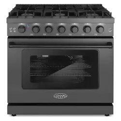
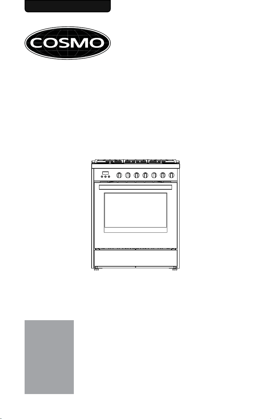
GAS RANGE
COS-305AGC
INSTALLATION MANUAL
READ AND SAVE THESE INSTRUCTIONS.
FOR RESIDENTIAL USE ONLY.
PLEASE LEAVE THIS GUIDE WITH THE HOMEOWNER.
PLEASE KEEP THIS GUIDE FOR FUTURE REFERENCE.
IMPORTANT:
INSTALLER:
HOMEOWNER:
30-IN FREESTANDING RANGE
Rev.22.07


1
THANK YOU FOR YOUR PURCHASE
Thank you for your purchase. We know that you have many brands and
products to choose from and we are honored to know that you have decided
to take one of our products into your home and hope that you enjoy it.
COSMO Appliances are designed according to the strictest safety and
performance standard for the North American market. We follow the most
advanced manufacturing philosophy. Each appliance leaves the factory after
thorough quality inspection and testing. Our distributors and our service
partners are ready to answer any questions you may have regarding how to
install, use and case for your products. We hope that this manual will help you
learn to use the product in the safest and most effective manner.
Before using this product, please read through this manual carefully. Keep
this user manual in a safe place for future reference. Please ensure that other
persons using this product are familiar with these instructions as well.
If you have any questions or concerns, please contact the dealer from whom you
purchased the product, or contact our Customer Support at:
1-888-784-3108
Reach us online at:
www.cosmoappliances.com

2
TABLE OF CONTENTS
RANGE SAFETY.................................................................................................... 3
Anti-tip Device ........................................................................................................... 4
INSTALLATION REQUIREMENTS ........................................................................ 6
Tools and Parts .......................................................................................................... 6
Location Requirements ............................................................................................ 8
Product Dimensions ................................................................................................ 10
Clearances .................................................................................................................. 11
Venting Requirements ............................................................................................. 12
Electrical Requirements ........................................................................................... 13
Gas Supply Requirements ...................................................................................... 16
INSTALLATION INSTRUCTIONS ......................................................................... 19
Unpack Range .......................................................................................................... 19
Install Anti-tip Device ............................................................................................. 20
Install Backsplash .................................................................................................... 22
Gas Connection ....................................................................................................... 23
Complete Connection ............................................................................................ 25
Adjust Flame Height .......................................................................................... 27
Level Range .............................................................................................................. 28
GAS CONVERSION ............................................................................................ 30
Convert Gas Pressure Regulator ........................................................................... 31
Convert Surface Burners ........................................................................................ 32
Convert Oven Bake Burner .................................................................................... 34
Convert Oven Broil Burner ..................................................................................... 35
Complete Gas Conversion ..................................................................................... 35
3
RANGE SAFETY
WARNING
Fire Hazard
If the information in this manual is not followed exactly, a fire or explosion
may result causing property damage, personal injury or death.
WARNING
Never Operate the Top Surface Cooking Section of this Appliance
Unattended.
DO NOT ATTEMPT TO EXTINGUISH AN OIL/GREASE FIRE WITH WATER
- Do not store or use gasoline or other flammable vapors and liquids in
the vicinity of this or any other appliance.
- WHAT TO DO IF YOU SMELL GAS
• Do not try to light any appliance.
• Do not touch any electrical switch.
• Do not use any phone in your building.
• Clear the room, building, or area of all occupants.
• Immediately call your gas supplier from a neighbor's phone. Follow
the gas supplier's instructions.
• If you cannot reach your gas supplier, call the fire department.
- Installation and service must be performed by a qualified installer,
service agency or the gas supplier.
• Failure to follow this warning statement could result in fire, explosion, or
burn hazard that could cause property damage, personal injury, or
death.
• If a fire should occur, keep away from the appliance and immediately
call your fire department.
4
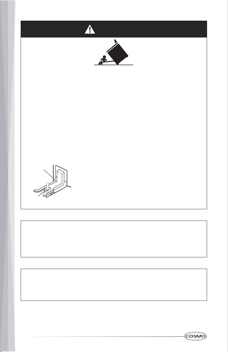
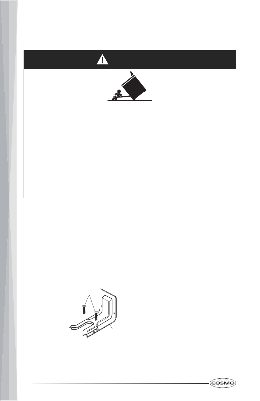
WARNING
Tip Over Hazard
Making sure the anti-tip bracket is installed:
WARNING: Gas leaks cannot always be detected by smell.
Gas suppliers recommend that you use a gas detector approved by UL or
CSA.
For more information, contact your gas supplier.
WARNING: Do not install a ventilation system that blows air downward
toward this cooking appliance. This type of ventilation system may cause
ignition and combustion problems with this cooking appliance resulting in
personal injury or unintended operation.
Anti-Tip
Bracket
Range
Foot
• A child or adult can tip the range and be killed.
• Install anti-tip bracket to floor or wall per installation instructions.
• Slide range back so rear range foot is engaged in the slot of the anti-tip
bracket.
• Re-engage the anti-tip bracket if range is moved.
• Do not operate the range without anti-tip bracket installed and
engaged.
• Failure to follow these instructions can result in death or serious burns to
children and adults.
• Slide range forward.
• Look for the anti-tip bracket securely attached
to floor and wall.
• Slide range back so rear range foot is under
anti-tip bracket.
5
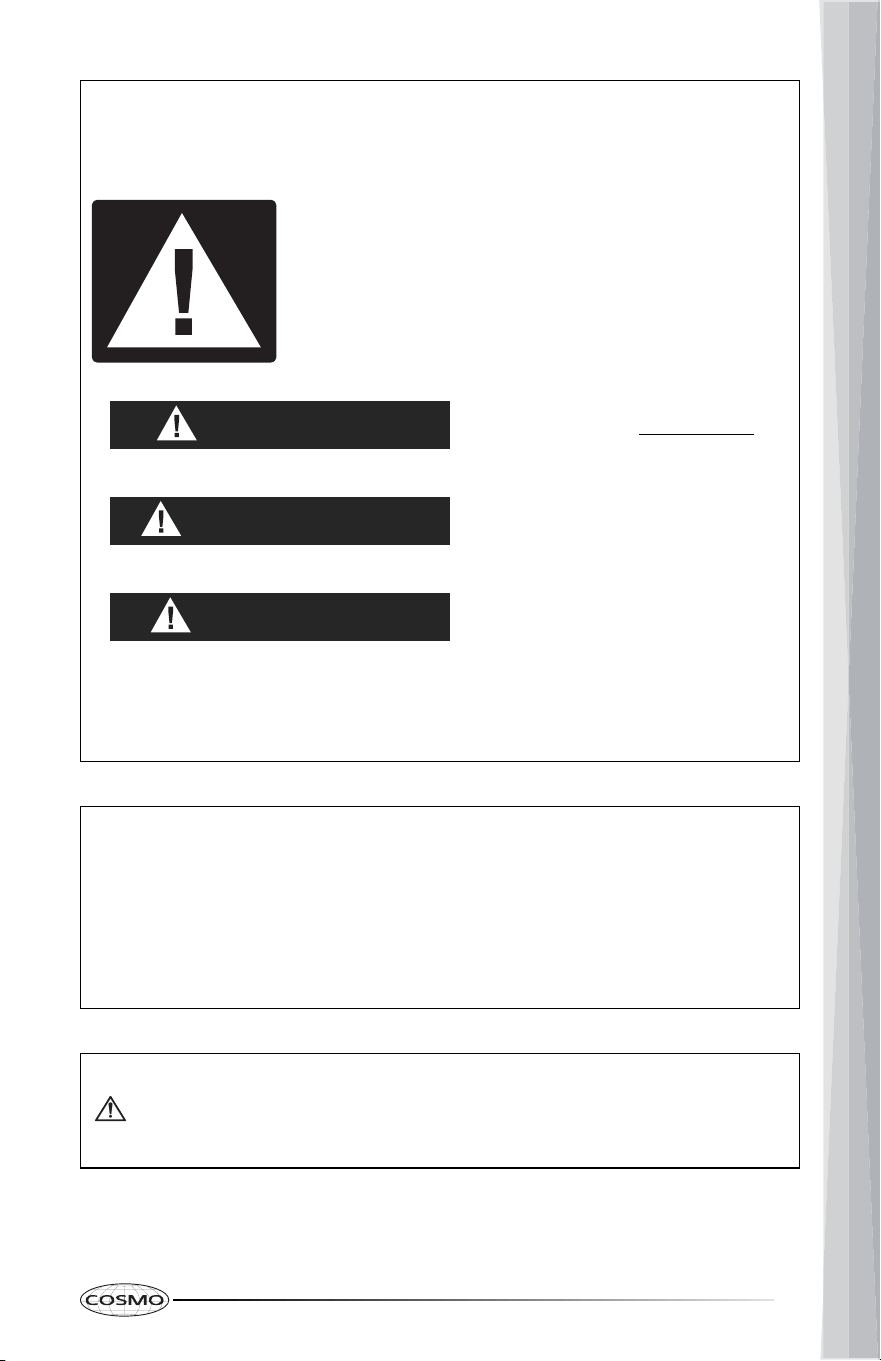
Your safety and the safety of others are very important.
We have provided many important safety messages in this manual and on
your appliance. Always read and obey all safety messages.
This is the safety alert symbol.
This symbol alerts you to potential hazards that can
kill or hurt you and others.
All safety messages will follow the safety alert symbol
and either the word "DANGER," "WARNING" or
"CAUTION." These words mean:
You can be killed or seriously
injured if you don't immediately
follow instructions.
DANGER
You can be killed or seriously
injured if you don't follow
instructions.
WARNING
A potentially hazardous situation
which, if not avoided, could result
in minor or moderate injury.
CAUTION
All safety messages will tell you what the potential hazard is, tell you how
to reduce the chance of injury, and tell you what can happen if the
instructions are not followed.
In the State of Massachusetts, the following installation instructions apply:
California Proposition 65 Warning
WARNING:
Cancer and Reproductive Harm - www.P65Warnings.ca.gov.
• Installations and repairs must be performed by a qualified or licensed
contractor, plumber, or gasfitter qualified or licensed by the State of
Massachusetts.
• If using a ball valve, it shall be a T-handle type.
• A flexible gas connector, when used, must not exceed 3 feet.
6
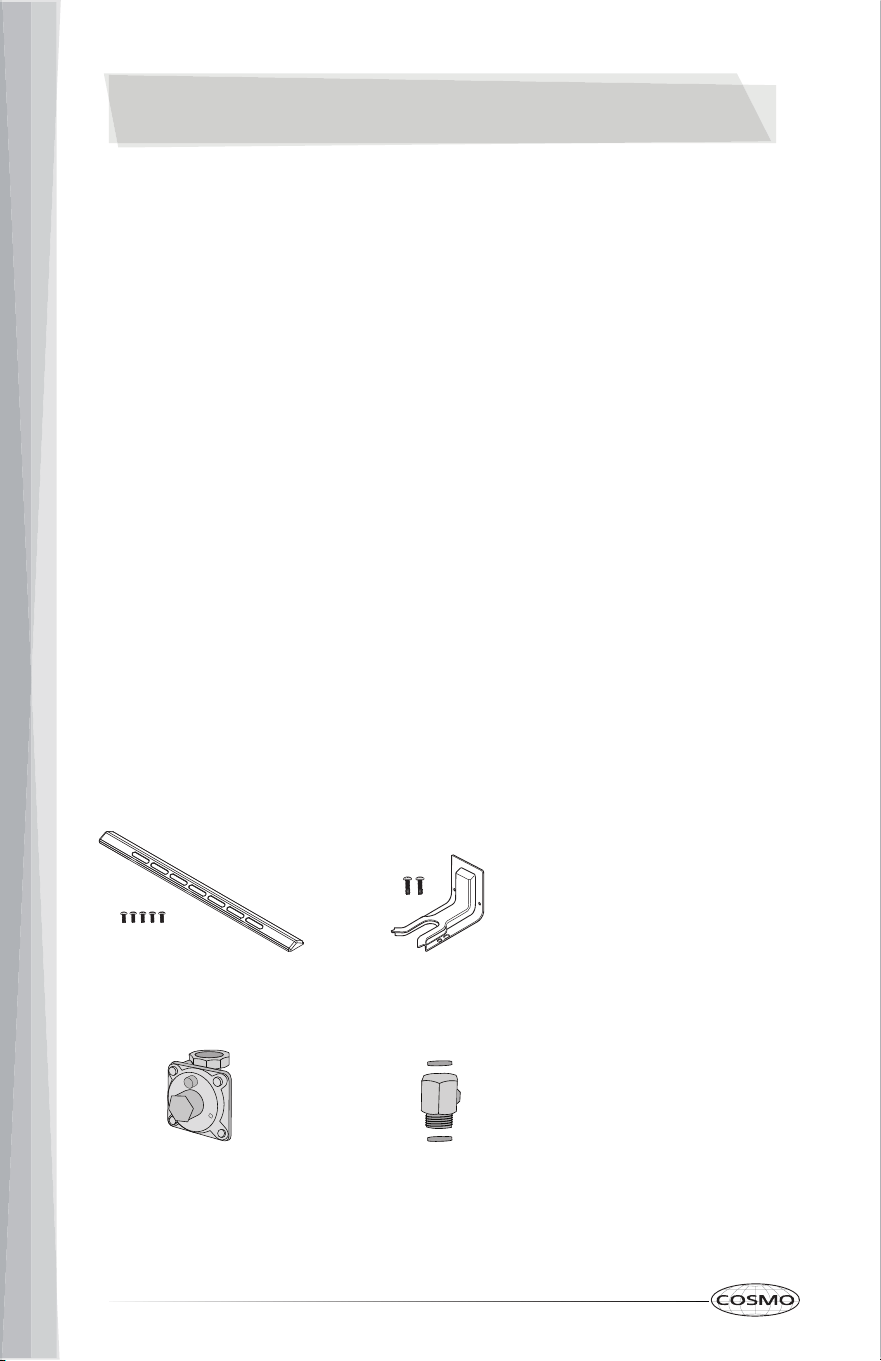
Backsplash with screws Anti-tip bracket with screws
Gas pressure regulator Gas pipe adapter with washers
INSTALLATION REQUIREMENTS
TOOLS AND PARTS
Gather the required tools and parts before starting installation. Read and
follow the instructions provided with any tools listed here.
Tools Needed
Parts Supplied
• Tape measure
• Flat-blade screwdriver
• Phillips screwdriver
• Level
• Drill
• Adjustable wrench or pliers
• Pipe wrench
• 1/8" (3.2 mm) drill bit (for wood
floors)
• Masonry drill bit (for
concrete/ceramic floors only)
• Marker or pencil
• Pipe-joint compound resistant to
Propane gas
• Noncorrosive leak-detection
solution
• Combination wrench
• Nut drive
• Masking tape
For Propane/Natural Gas
Conversions
7
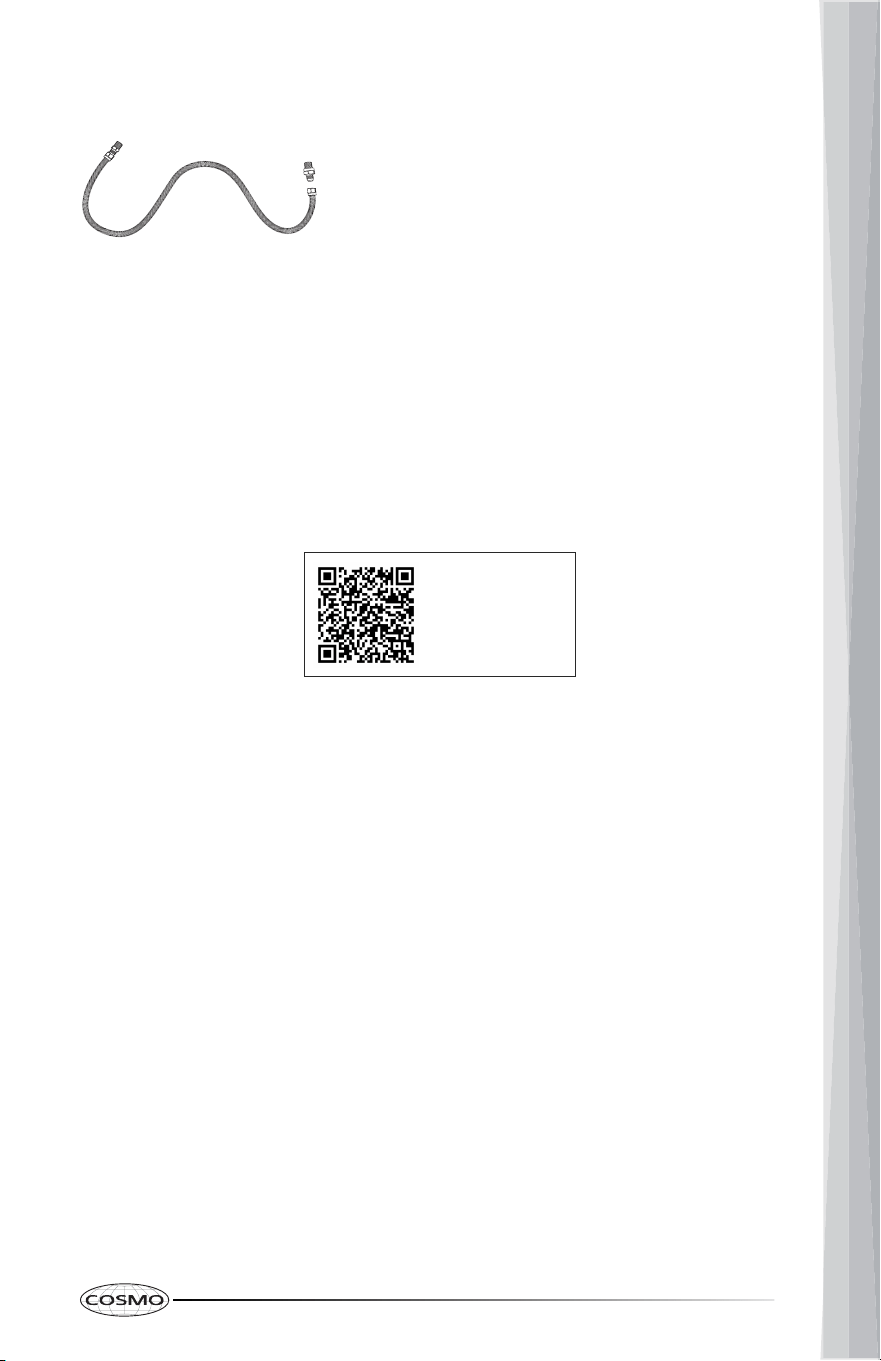
Parts Needed
Scan to find
available LP kits
Gas supply line kit
(supply line and 2 adapters)
Optional Parts
To purchase these or any other accessories, please visit
www.cosmoappliances.com or reference the contact information at the end
of this manual.
• LP conversion kits
8
LOCATION REQUIREMENTS
IMPORTANT: Observe all governing codes and ordinances. Do not obstruct
flow of combustion and ventilation air.
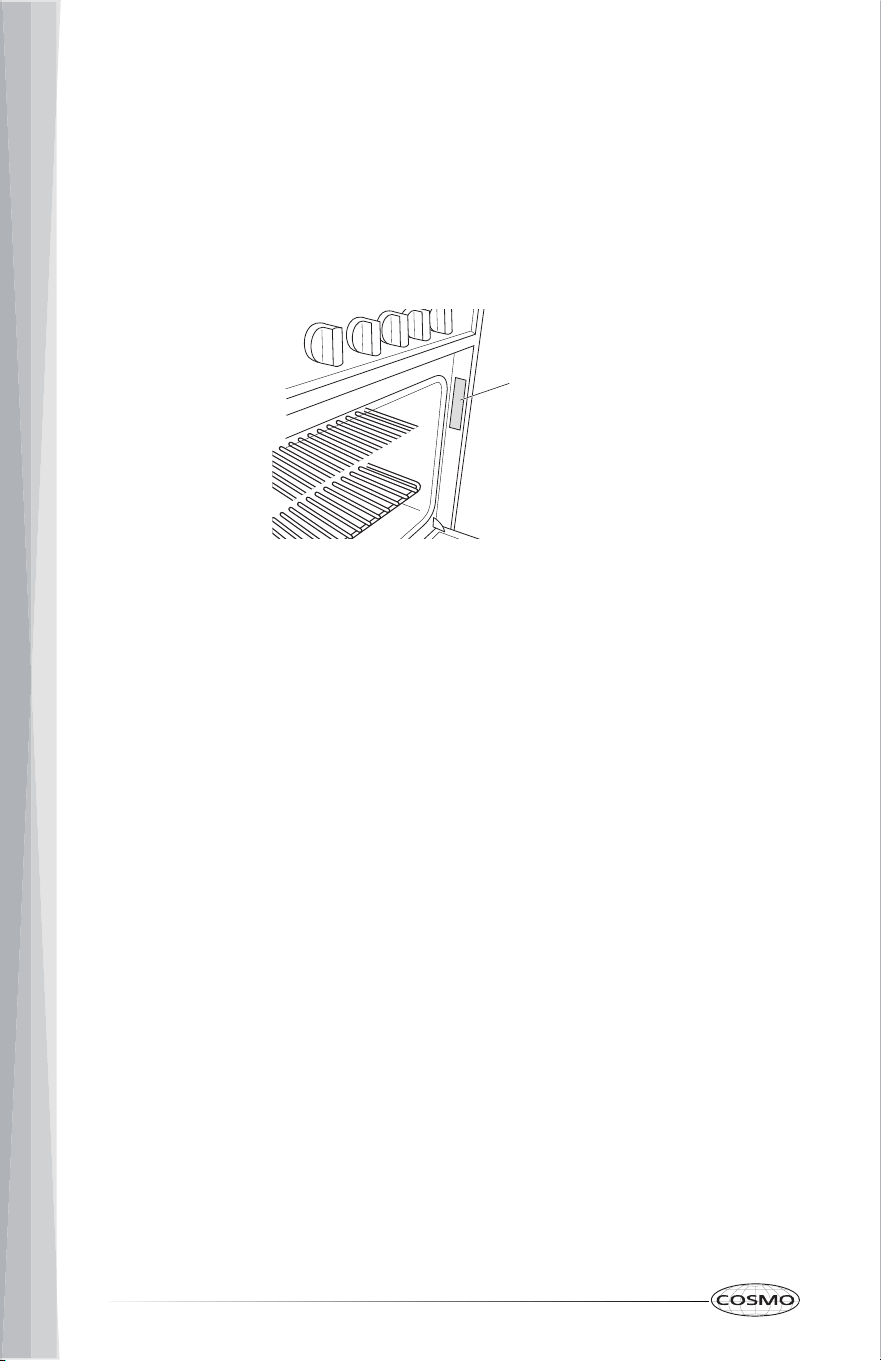
Rating Plate
• It is the installer's responsibility to comply with installation clearances
specified on the model/serial rating plate. The model/serial rating plate is
located behind the oven door on the oven frame.
• The range should be located for convenient use in the kitchen.
• Recessed installations must provide complete enclosure of the sides and
rear of the range.
• To eliminate the risk of burns or fire by reaching over heated surface
units, cabinet storage space located above the surface units should be
avoided. If cabinet storage is to be provided, the risk can be reduced by
installing a range hood or microwave hood combination that projects
horizontally a minimum of 5" (12.7 cm) beyond the bottom of the cabinets.
• All openings in the wall or floor where range is to be installed must be
sealed.
• Do not seal the range to the side cabinets.
• Cabinet opening dimensions that are shown must be used.
• Grounded electrical supply is required. See "Electrical Requirements"
section.
• Proper gas supply connection must be available. See "Gas Supply
Requirements" section.
• Contact a qualified floor covering installer to check that the floor covering
can withstand at least 200°F (93°C).
• Use an insulated pad or 1/4" (0.64 cm) plywood under range if installing
range over carpeting.

9
Mobile Home - Additional Installation Requirements
• The installation of this range must conform to the Manufactured Home
Construction and Safety Standard, Title 24 CFR, Part 3280 (formerly the
Federal Standard for Mobile Home Construction and Safety, Title 24, HUD
Part 280). When such standard is not applicable, use the Standard for
Manufactured Home Installations, ANSI A225.1/NFPA 501A or with local
codes.
In Canada, the installation of this range must conform with the current
standards CAN/CSA-A240-latest edition, or with local codes.
Mobile Home Installations Require:
• When this range is installed in a mobile home, it must be secured to the
floor during transit. Any method of securing the range is adequate as
long as it conforms to the standards listed above.
• Four-wire power supply cord or cable must be used in a mobile home
installation. The appliance wiring will need to be revised. See "Electrical
Connection" section.
10
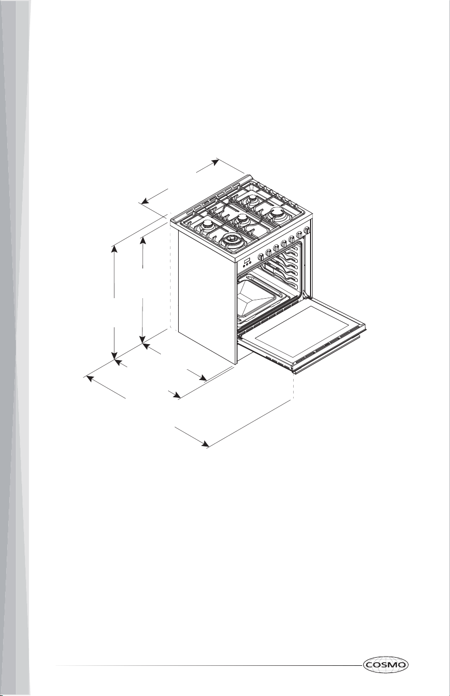
PRODUCT DIMENSIONS
This manual covers several models. Your model may appear different from
the models depicted. Dimensions given are maximum dimensions across all
models.
29.8 in
(758 mm)
35.4 in
(900 mm)
To cooktop
36.4 in
(925 mm)
To grate
27.0 in
(686 mm)
With handle
46.2 in
(1174 mm)
Door fully open
25.0 in
(635 mm)
COS-305AGC
11
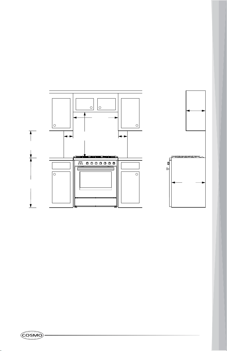
CLEARANCES
IMPORTANT: Some cabinet and building materials are not designed to
withstand the heat produced by the oven for baking and self-cleaning. Check
with your builder or cabinet supplier to make sure that the materials used will
not discolor, delaminate or sustain other damage.
GIVEN DIMENSIONS ARE MINIMUM CLEARANCES.
NOTE:
24 in
(61 cm)
Lower
Cabinet
Depth
13 in
(33 cm)
Maximum
36 in
(91.4 cm)
18 in
(45.7 cm)
30 in
(76.2 cm)
30 in
(76.2 cm)
6 in
(15.2 cm)
to right
wall
6 in
(15.2 cm)
to left
wall
Overhead
Cabinet
Depth
• 30" (76.2 cm) minimum clearance between cooking surface and bottom
of the overhead cabinet.
• 18" (45.7 cm) minimum clearance from upper cabinet to countertop on
either side of unit.
12
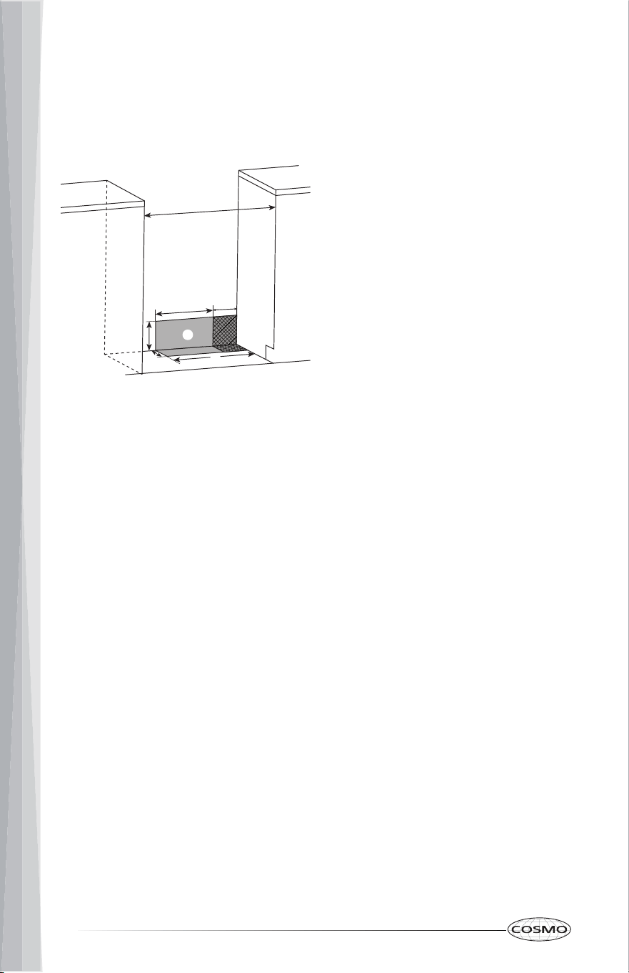
Power Supply Location
IMPORTANT: An electrical outlet in the floor, may be either recessed or
surface mounted, but an electrical outlet in the wall must be recessed to make
the connection. For Direct Wiring, the electrical box should be mounted to the
wall.
VENTING REQUIREMENTS
IMPORTANT: This range must be exhausted outdoors unless you are using
ductless venting. Observe all governing codes and ordinances. Do not
obstruct flow of combustion and ventilation air.
a
b
e
d
g
h
c
f
30" (76 cm)
11½" (29.2 cm)
6" (15.2 cm)
7¼" (18.4 cm)
3" (7.6 cm)
17½" (44 cm)
Recommended Location for
Electrical Outlet
Recommended Location for
Gas Supply Connection
a
b
c
d
e
f
g
h
• Do not terminate the vent system in an attic or other enclosed area.
• Use an approved vent cap for proper performance. If an alternate wall or
roof cap is used, be certain the cap size is not reduced and that it has a
backdraft damper.
• Vent system must terminate to the outside unless you are using a ductless
vent kit.
• Rigid metal vent is recommended. For best performance, do not use
plastic or metal foil vent.
• If a joist or stud must be cut, then a supporting frame must be
constructed.
• The size of the vent should be uniform.
• The vent system must have a damper.
• Seal all joints in the vent system.
• Use caulking to seal exterior wall or roof opening around the cap.
• Determine which venting method is best for your application.
13
Makeup Air
Local building codes may require the use of makeup air systems when using
ventilation systems greater than specified CFM of air movement. The specified
CFM varies from locale to locale. Consult your HVAC professional for specific
requirements in your area.
ELECTRICAL REQUIREMENTS
WARNING
Electrical Shock Hazard
Electrically ground range.
Failure to do so can result in death, fire or electrical shock.
Electrical Grounding Instructions
This appliance is equipped with a three-prong grounding plug for your
protection against shock hazard and should be plugged directly into a
properly grounded receptacle. Do not cut or remove the grounding prong
from this plug.
This range is equipped with an electronic ignition system that will not operate
if plugged into an outlet that is not properly polarized.
If codes permit and a separate ground wire is used, it is recommended that a
qualified electrical installer determine that the ground path is adequate and
wire gauge is in accordance with local codes.
Do not use an extension cord.
WARNING: Improper connection of the equipment-grounding conductor can
result in a risk of electric shock. Check with a qualified electrician or service
technician if you are in doubt as to whether the appliance is properly
grounded. Do not modify the power supply cord plug. If it will not fit the
outlet, have a proper outlet installed by a qualified electrician.

14
ELECTRICAL REQUIREMENTS - U.S.A. ONLY
Be sure that the electrical connection and wire size are adequate and in
conformance with the National Electrical Code, ANSI/ NFPA No. 70-latest
edition and all local codes and ordinances.
A copy of the above code standards can be obtained from:
National Fire Protection Association
1 Batterymarch Park
Quincy, MA 02169
Electrical Connection
• Check local codes and consult gas supplier. Check existing electrical
supply and gas supply. It is recommended that all electrical connections
be made by a licensed, qualified electrical installer.
• Range must be connected to the proper electrical voltage and frequency
as specified on the model/serial rating plate. The plate is located behind
the oven door on the oven frame. Refer to the illustrations in the "Location
Requirements" section.
• A 120 volt, 60 Hz, AC only, 15-amp fused, electrical circuit is required. A
time- delay fuse or circuit breaker is also recommended. It is
recommended that a separate circuit serving only this range be provided.
• Electronic ignition systems operate within wide voltage limits, but proper
grounding and polarity are necessary. Check that the outlet provides 120-
volt power and is correctly grounded.
• This gas range is not required to be plugged into a GFCI (Ground-Fault
Circuit Interrupter) outlet. It is recommended that you not plug an electric
spark ignition gas range or any other major appliance into a GFCI wall
outlet as it may cause the GFCI to trip during normal cycling.
• Performance of this range will not be affected if operated on a GFCI-
protected circuit. However, occasional nuisance tripping of the GFCI
breaker is possible due to the normal operating nature of electronic gas
ranges.
• The wiring diagram is located on the back of the range in a clear plastic
bag.
NOTE: The metal chassis of the range must be grounded in order for the
control panel to work. If the metal chassis of the range is not grounded, no
keypads will operate. Check with a qualified electrician if you are in doubt as
to whether the metal chassis of the range is grounded.

15
ELECTRICAL REQUIREMENTS - CANADA ONLY
Be sure that the electrical connection and wire size are adequate and in
conformance with the CSA Standard C22.1, Canadian Electrical Code, Part 1 -
latest edition and all local codes and ordinances.
A copy of the above code standards can be obtained from:
Canadian Standards Association
178 Rexdale Blvd.
Toronto, ON M9W 1R3 CANADA
Electrical Connection
Check local codes and consult gas supplier. Check existing electrical supply
and gas supply. It is recommended that all electrical connections be made by
a licensed, qualified electrical installer.
• Check with a qualified electrical installer if you are not sure the range is
properly grounded.
• A time-delay fuse or circuit breaker is recommended.
• This range is equipped with a CSA International Certified Power Cord
intended to be plugged into a standard 14-50R wall receptacle. Be sure
the wall receptacle is within reach of range's final location.
• Do not use an extension cord.
• The wiring diagram is located on the back of the range in a clear plastic
bag.
NOTE: The metal chassis of the range must be grounded in order for the
control panel to work. If the metal chassis of the range is not grounded, no
keypads will operate. Check with a qualified electrician if you are in doubt as
to whether the metal chassis of the range is grounded.
16
GAS SUPPLY REQUIREMENTS
WARNING
Failure to do so can result in death, explosion or fire.
• licensed heating personnel
• authorized gas company personnel
• authorized service personnel
IMPORTANT:
TYPE OF GAS
Natural Gas:
This range is design-certified by CSA International for use with natural gas or,
after proper conversion, for use with LP gas.
This range is factory-set for use with Natural gas. The model/serial rating
plate located on the right side oven door trim has information on the types of
gas that can be used. If the types of gas listed do not include the type of gas
available, check with the local gas supplier.
• Observe all governing codes and ordinances.
• This installation must conform with all local codes and ordinances. In the
absence of local codes, installation must conform with American National
Standard, National Fuel Gas Code ANSI Z223.1 - latest edition or, in
Canada, CAN/CGA B149 - latest edition.
• Leak testing of the range must be conducted according to the
manufacturer's instructions. Do not use a flame to check for leaks.
Explosion Hazard
Use a new CSA International approved gas supply line.
Install a shut-off valve.
Securely tighten all gas connections.
If connected to LP, have a qualified person make sure gas pressure does
not exceed the maximum pressure listed in this section.
Examples of a qualified person include:

17
LP Gas Conversion:
Conversion must be performed by a qualified service technician. The qualified
agency performing this work assumes the gas conversion responsibility.
No attempt shall be made to convert the appliance from the gas specified on
the model/serial rating plate for use with a different gas without consulting
the serving gas supplier. See "GAS CONVERSION" section.
GAS SUPPLY LINE
Provide a gas supply line of 3/4" (1.9 cm) rigid pipe to the range location. A
smaller size pipe on longer runs may result in insufficient gas supply. Pipe-joint
compounds that resist the action of LP gas must be used. With LP gas, piping
or tubing size can be 1/2" (1.3 cm) minimum. Usually, LP gas suppliers
determine the size and materials used in the system.
Flexible metal appliance connector:
• If local codes permit, a new CSA design-certified, 4 - 5 ft (122 - 152.4 cm)
long, 1/2" (1.3 cm) or 3/4" (1.9 cm) I.D., flexible metal appliance connector
may be used for connecting range to the gas supply line.
• A 1/2" (1.3 cm) male pipe thread is needed for connection to the female
pipe threads of the inlet to the appliance pressure regulator.
• Do not kink or damage the flexible metal tubing when moving the range.
Rigid pipe connection:
Since the range must be pulled away from the installation space to provide
access to the gas regulator connections, and because hard piping restricts
movement of the range, the range can only be installed using a CSA
International-certified flexible metal appliance connector.
If local codes require a hard-piped connection, a combination of pipe fittings
must be used to connect the range to the existing gas line and maintain an
accessible working space behind the range. Consult with a qualified local
technician for an optimal connection suitable for your installation.
18
Gas shutoff valve:
A manual gas line shut-off valve must be installed in an easily accessible
location. Do not block access to shut-off valve. The valve is for turning on or
shutting off gas to the range.
GAS PRESSURE REGULATOR
The gas pressure regulator supplied with this range must be used. The inlet
pressure to the regulator should be as follows for proper operation:
Contact local gas supplier if you are not sure about the inlet pressure.
Burner Input Requirements
Input ratings shown on the model/serial rating plate are for elevations up to
2,000 ft (609.6 m).
For elevations above 2,000 ft (609.6 m), ratings are reduced at a rate of 4%
for each 1,000 ft (304.8 m) above sea level (not applicable for Canada).
GAS SUPPLY PRESSURE TESTING
Gas supply pressure for testing regulator must be at least 1" (2.5 cm) water
column pressure above the manifold pressure shown on the model/serial
rating plate.
Line pressure testing above 0.5 psi gauge (14" WCP)
The range and its individual shutoff valve must be disconnected from the gas
supply piping system during any pressure testing of that system at test
pressures in excess of 0.5 psi (3.5 kPa).
Line pressure testing at 0.5 psi gauge (14" WCP) or lower
The range must be isolated from the gas supply piping system by closing its
individual manual shutoff valve during any pressure testing of the gas supply
piping system at test pressures equal to or less than 1/2 psi (3.5 kPa).
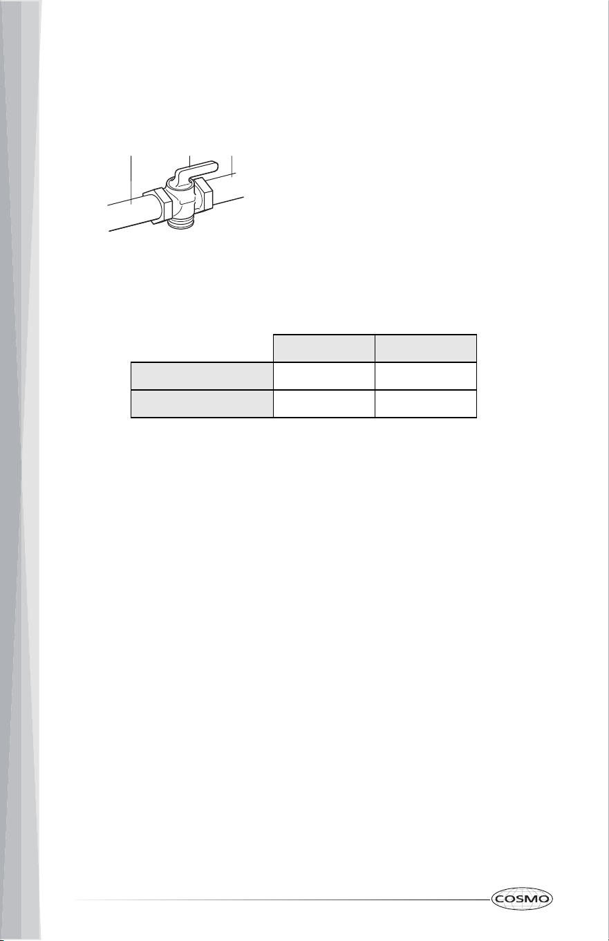
a b c
Gas Supply Line
Shutoff Valve "Open" Position
To Range
a
b
c
Natural gas LP gas
Minimum pressure 4" WCP 10" WCP
Maximum pressure 7" WCP 11" WCP
19
INSTALLATION INSTRUCTIONS
IMPORTANT: This appliance shall be installed only by authorized persons and
in accordance with the manufacturer's installation instructions, local gas
fitting regulations, municipal building codes, electrical wiring regulations,
local water supply regulations.
UNPACK RANGE
WARNING
Excessive Weight Hazard
Use two or more people to move and install range.
Failure to do so can result in back or other injury.
NOTES:
1. Remove shipping materials, tape and film from the range. Keep
cardboard bottom under range. Do not dispose of anything until the
installation is complete.
2. Remove oven racks and parts package from oven and shipping materials.
3. To remove cardboard bottom, first take 4 cardboard corners from the
carton. Stack one cardboard corner on top of another. Repeat with the
other 2 corners. Place them lengthwise on the floor behind the range to
support the range when it is laid on its back.
4. Using two or more people, firmly grasp the range and gently lay it on its
back on the cardboard corners.
5. Remove cardboard bottom.
• The leveling legs can be adjusted while the range is on its back.
• To place range back up into a standing position, put a sheet of
cardboard or hardboard on the floor in front of range to protect the
flooring. Using two or more people, stand range back up onto the
cardboard or hardboard.
20
INSTALL ANTI-TIP DEVICE
WARNING
Tip Over Hazard
IMPORTANT:
a
16 x 1⁵⁄₈" Screws (2)
Anti-tip Bracket
a
b
b
• A child or adult can tip the range and be killed.
• Install anti-tip bracket to floor or wall per installation instructions.
• Slide range back so rear range foot is engaged in the slot of the anti-tip
bracket.
• Re-engage the anti-tip bracket if range is moved.
• Do not operate the range without anti-tip bracket installed and
engaged.
• Failure to follow these instructions can result in death or serious burns to
children and adults.
• An anti-tip bracket is provided with the range. The anti-tip bracket uses a
rear range foot to secure the range to the floor or wall.
• Attach the anti-tip bracket to the floor or wall so that the rear range foot
will be centered within the bracket when the range is pushed into its final
position.
1. Remove the anti-tip bracket and screws from the parts bag.
NOTE: The anti-tip bracket must be securely mounted to the subfloor or
wall. The flooring's thickness may require longer screws to anchor bracket
to subfloor.
21
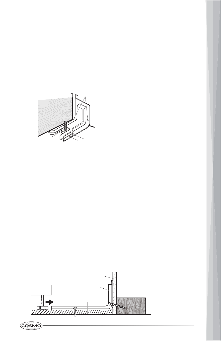
Distance from Adjacent Cabinet
(3/8" to 1/2" [0.95 cm to 1.27 cm])
Wall Holes
Concrete Floor Holes
Wood Floor Holes
Rear Range Foot
a
b
a
b
d
c
d
c
e
Wall
Anti-tip
Bracket
Floor
a
b
c
a
b
c
e
2. Place the bracket so that the back of the bracket is against the rear wall
and the side edge of the bracket is 3/8" to 1/2" from the adjacent cabinet.
NOTE: If there is no adjacent cabinet, place the bracket so that the edge
of the bracket is 3/8" to 1/2" in from the range side panel. If the
countertop overhangs the cabinet, offset the bracket from the cabinet by
the depth of the overhang plus an additional 3/8" to 1/2".
3. Using the anti-tip bracket as a template, mark the two holes for either a
Floor Wood, Floor Concrete, or Wall installation, as shown.
4. Drill two pilot holes where marked. Follow the instructions specific to your
construction.
NOTE: A nail or awl may be used to create a pilot hole, if a drill is not
available. For concrete construction 1/4" x 1 ½" Lag Bolts and 1/2" O.D.
Sleeve Anchors are required.
Wood
• Floor - Drill a 1/8" pilot hole, as shown.
NOTE: Contact a qualified floor covering installer for the best
procedure for drilling mounting holes through your type of floor
covering.
• Wall - Drill an angled 1/8" pilot hole, as shown.
Concrete
• Drill the size hole recommended for the anchors into the concrete at
the center of the holes identified as Floor Concrete or Wall.
22
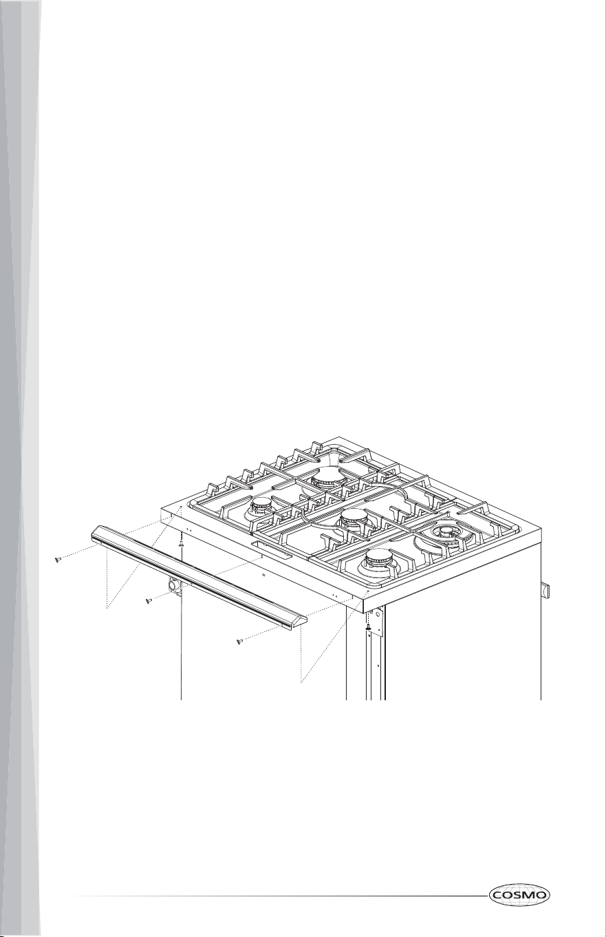
INSTALL BACKSPLASH
5. Install the anti-tip bracket.
Wood
• Using the two screws (provided) fasten the anti-tip bracket to the
floor or wall.
NOTE: The screw must enter wood or metal.
Concrete
• Insert the sleeve anchor into the drilled holes and then insert the lag
bolts through the anti-tip bracket and into the floor or wall. The bolts
must be properly tightened as recommended for the hardware.
• Install the backsplash to rear of range with the screws provided.
23
GAS CONNECTION
WARNING
• licensed heating personnel
• authorized gas company personnel
• authorized service personnel
Failure to do so can result in death, explosion or fire.
Explosion Hazard
Use a new CSA International approved gas supply line.
Install a shut-off valve.
Securely tighten all gas connections.
If connected to LP, have a qualified person make sure gas pressure does
not exceed the maximum pressure listed in the "Gas Supply Requirement"
section.
Examples of a qualified person include:
This appliance shall be installed only by authorized persons and in
accordance with the manufacturer's installation instructions, local gas fitting
regulations, municipal building codes, electrical wiring regulations, local
water supply regulations. The agency performing this work assumes
responsibility for the quality of work performed, including checking for leaks
and ensuring installation meets code requirements.
This range is factory-set for use with Natural gas. To use this range with
Propane gas, see the "GAS CONVERSION" section before connecting this
range to the gas supply. Gas conversions from Natural gas to Propane gas or
from Propane gas to Natural gas must be done by a qualified installer.
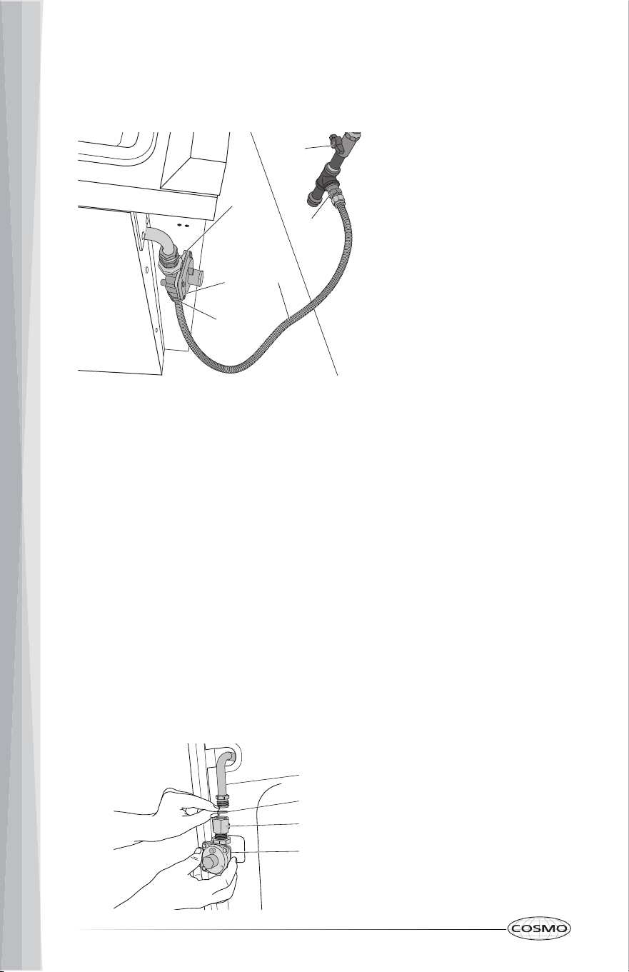
TYPICAL FLEXIBLE CONNECTION
1. Apply pipe-joint compound made for use with LP gas to the smaller
thread ends of the flexible connector adapters.
24
b
c
e
a
d
d
Adapter (provided)
Gas Pressure Regulator
Gas Supply Line
Adapters (From Gas
Supply Line Kit)
Gas Shutoff Valve
b
a
c
d
e
a
b
c
d
Gas Line from Range
Washer (provided)
Adapter (provided)
Gas Pressure Regulator
(provided)
a
b
c
d
2. Attach one adapter to the gas pressure regulator and the other adapter
to the gas shutoff valve. Tighten both adapters, being certain not to
move or turn the gas pressure regulator.
3. Use a 15/16" (2.4 cm) combination wrench and channel lock pliers to
attach the flexible connector to the adapters. Check that connector is not
kinked.
TYPICAL RIGID PIPE CONNECTION
A combination of pipe fittings must be used to connect the range to the
existing gas line and maintain an accessible working space behind the range.
Your connections may be different according to the supply line type, size and
location. Consult with a qualified local technician for an optimal connection
suitable for your installation.
1. Apply pipe-joint compound made for use with LP gas to all pipe thread
connections.
2. Using a pipe wrench to tighten, connect the gas supply to the range.
25
CONVERT TO LP GAS (OPTIONAL)
This range is shipped from the factory set up to use natural gas. It can be
converted to use LP gas by a qualified service technician.
The LP conversion kit is sold separately. The conversion to LP requires all
surface burner orifices and, if applicable, gas oven orifices to be changed. In
addition, the nozzle on the gas pressure regulator needs to be reversed.
See "GAS CONVERSION" section for detailed instructions.
NOTE: All replaced orifices must be left with the consumer, including the
instructions and retrofit sizes and orifice indication.
COMPLETE INSTALLATION
WARNING
Electrical Shock Hazard
Disconnect power before servicing.
Plug into a grounded 3-prong outlet.
Do not use an adapter or an extension cord.
Failure to do so can result in death, fire, or electrical shock
1. Open the manual shutoff valve in the gas supply line. The valve is open
when the handle is parallel to the gas pipe.
2. Test all connections by brushing on an approved noncorrosive leak-
detection solution. If bubbles appear, a leak is indicated. Correct any leak
found.
26
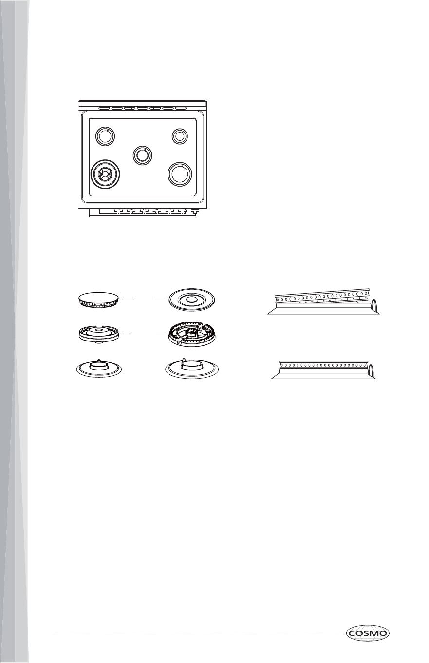
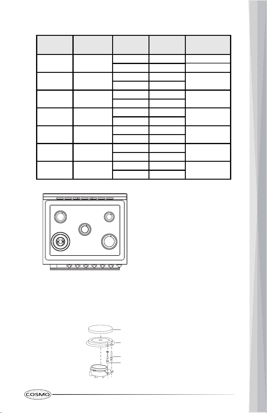
A. Triple Ring (X-Large)
B. Rapid (Large)
C. Semi Rapid (Medium)
D. Auxiliary (Small)
C D
C
A B
Triple Ring Burner
Auxiliary Burner
Semi Rapid Burner
Rapid Burner
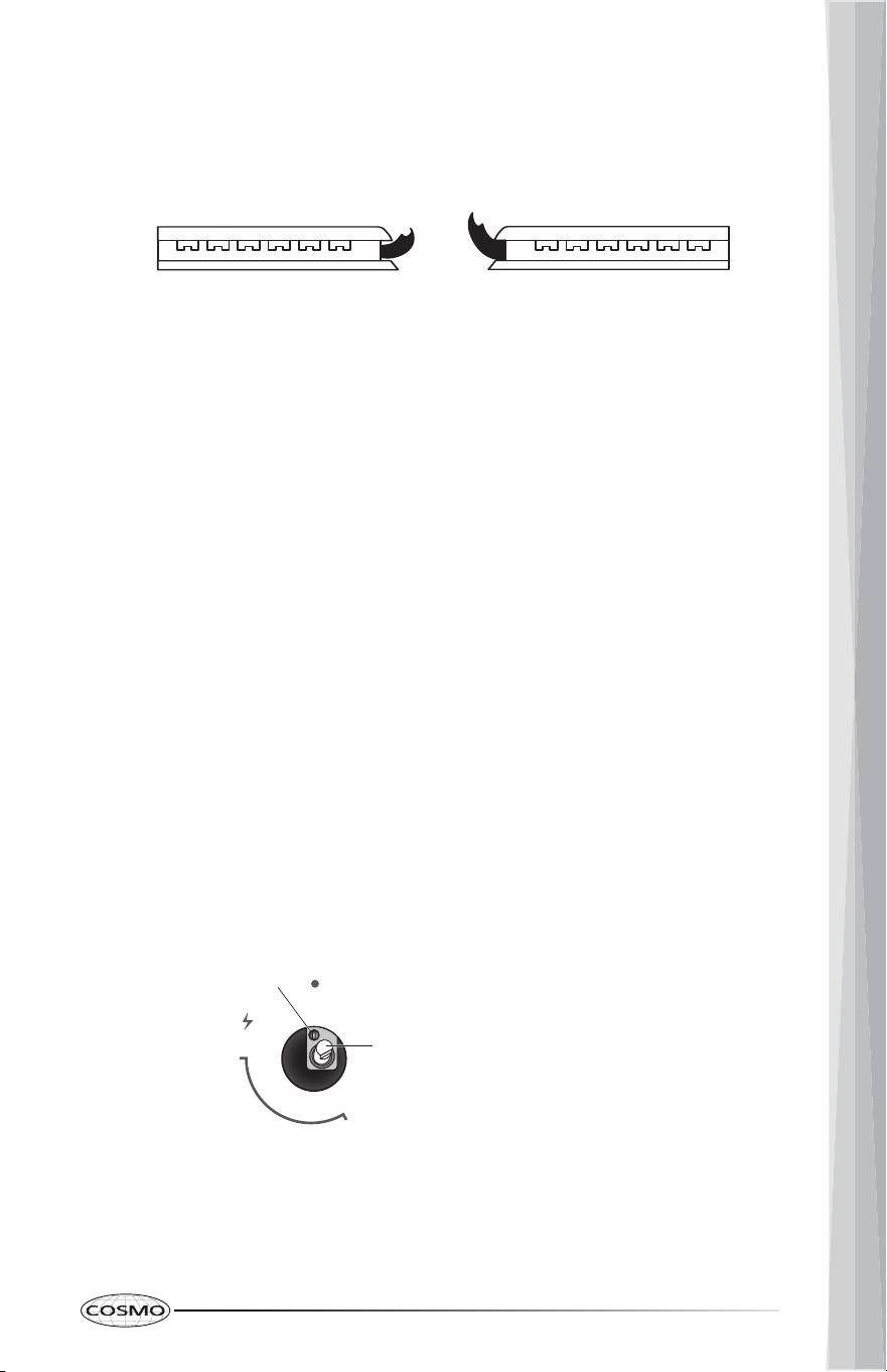
Correctly Positioned
Incorrectly Positioned
Cap
Base
3. Remove, if any, packaging tapes securing the burners on the surface. If
the cooktop burner bases and caps are not pre-installed, remove them
from package containing parts, align and place the burner bases and
caps accordingly.
Note: Align notches in burner caps with pins in burner base. Burner caps
should be level when properly positioned. If burner caps are not properly
positioned, surface burners will not light.
4. Place burner grates over burners and caps.
5. Plug in range or reconnect power.
27
ADJUST FLAME HEIGHT
Check and adjust the height of top burner flames. The cooktop "low" burner
flame should be a steady blue flame approximately 1/4" (6 mm) high. Propane
gas flames have a slightly yellow tip.
If burners do not light properly:
To adjust standard burner:
IMPORTANT: Adjustments must be made with two other burners in operation
on a medium setting. This prevents the upper row of flames from being set too
low, resulting in the flame being extinguished when other burners are turned
on.
The flame can be adjusted using the adjustment screw in the center of the
valve stem. The valve stem is located directly behind the control knob.
ig lameLow lame
MAX
MIN
OFF
a
b
Adjustment Screw
Control Knob Stem
a
b
1. Turn burner control knob to the "OFF" position.
2. Check that the range is plugged in. Check that the circuit breaker has not
tripped or the household fuse has not blown.
3. Check that the gas shutoff valves are set to the "open" position.
4. Check that burner caps are properly positioned on burner bases.
1. Light the burner and turn the knob to the lowest setting (MIN).
2. Pull and remove the control knob.
3. Insert a small, flat-blade screwdriver into the adjustment screw, and
slowly turn the screw until the flame appearance is correct.
• Open the valve more if the flames are too small or fluttered.
• Close the valve more if the flames are too large.
4. Replace the control knob.
5. Test and check the flame by turning the control knob from the lowest to
the highest settings.

28
NOTE: For burners (on some models) with safety valve, make sure that the
regulation obtained is sufficient to maintain heating of the thermocouple. If it
is not, increase the minimum flame.
ABNORMAL OPERATION
ANY OF THE FOLLOWING ARE CONSIDERED TO BE ANBORMAL OPERATION
AND MAY REQUIRE SERVICING:
IN CASE THE APPLIANCE FAILS TO OPERATE CORRECTLY, CONTACT THE
AUTHORIZED SERVICE PROVIDE IN YOUR AREA.
THE BURNERS REQUIRE NO REGULATION OF THE PRIMARY AIR.
LEVEL RANGE
IMPORTANT: Do not operate the range if its rear foot is not completely
engaged in the anti-tip bracket. Never completely remove the leveling legs or
the range will not be secured to the anti-tip device properly.
• Yellow burner flames.
• Sooting up of cooking utensils.
• Burners not igniting properly.
• Burners failing to remain lit.
• Burners extinguished by oven door.
• Gas valves, which are difficult to turn.
NOTE: The range must be level for optimum cooking and baking
performance.
1. Slide range into final location, making sure rear leveling leg slides into the
anti- tip bracket. Leave a 1" (2.5 cm) gap between the back of the range
and the back wall.
2. Check that the range is level by placing a level on the oven bottom. If
needed, use a wrench to adjust the height of the leveling legs until the
range is level from side to side and from front to back.
29
VERIFY ANTI-TIP BRACKET ENGAGEMENT
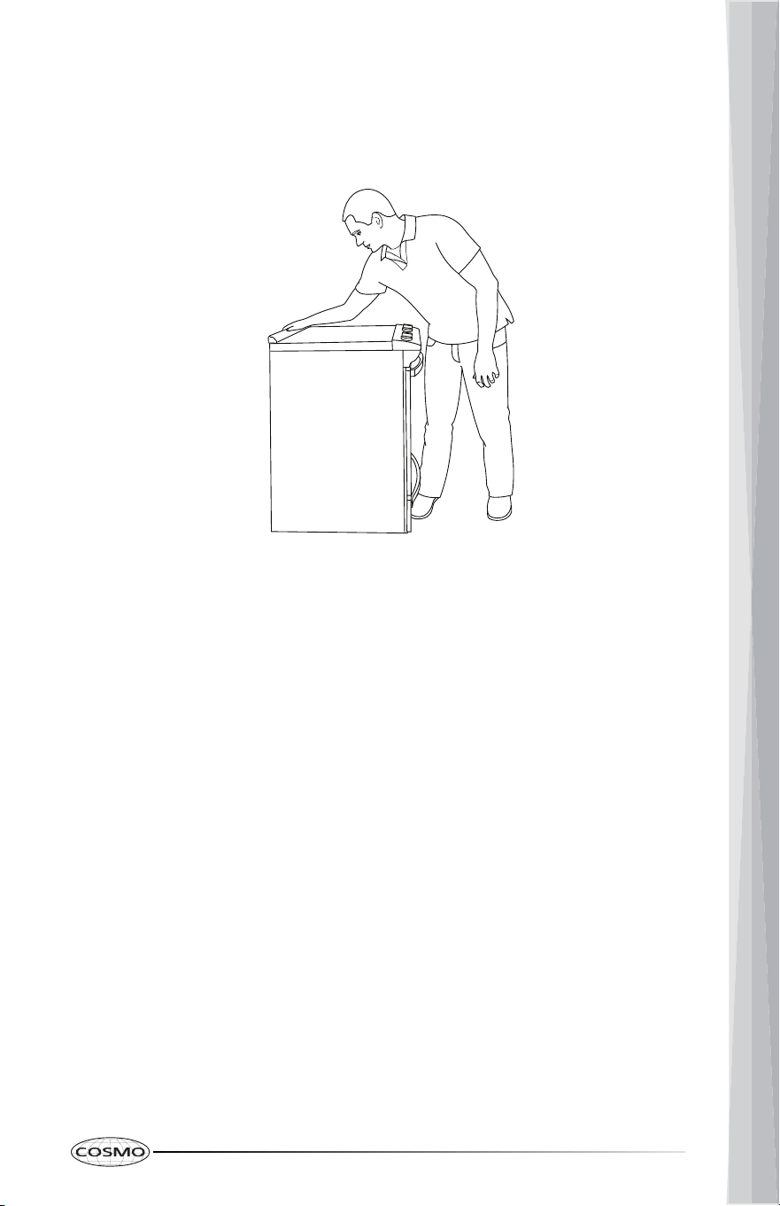
1. Place the outside of your foot against the bottom of the front panel to
keep the range from moving, and then grasp the back of the range, as
shown.
2. Slowly attempt to tilt the range forward.
• If you encounter immediate resistance, the range foot is engaged in
the anti-tip bracket. Range installation is completed.
• If the rear of the range lifts more than 1/2" (1.3 cm) off the floor
without resistance, stop tilting the range and lower it gently back to
the floor. The range foot is not engaged in the anti-tip bracket.
Proceed to Steps 3 and 4.
IMPORTANT: If there is a snapping or popping sound when tilting the
range, the range may not be fully engaged in the bracket. Check to
see if there are obstructions keeping the range from sliding to the
wall or keeping the range foot from sliding into the bracket. Verify
that the bracket is held securely in place by the mounting screws.
3. Slide the range forward, and verify that the anti-tip bracket is securely
attached to the floor or wall.
4. Slide range back so the rear range foot is inserted into the slot of the anti-
tip bracket.
IMPORTANT: If the range is pulled away from the wall for any reason, always
verify anti-tip bracket engagement again.
30
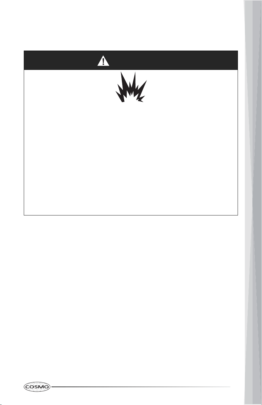
GAS CONVERSION
WARNING
Explosion Hazard
Use a new CSA International approved gas supply line and install a shut-
off valve for new installations.
Securely tighten all gas connections.
If connected to LP, have a qualified person make sure gas pressure does
not exceed the maximum pressure listed in the "Gas Supply Requirement"
section.
Examples of a qualified person include:
• licensed heating personnel
• authorized gas company personnel
• authorized service personnel
Failure to do so can result in death, explosion or fire.
WARNING
Tip Over Hazard
• A child or adult can tip the range and be killed.
• Install anti-tip bracket to floor or wall per installation instructions.
• Slide range back so rear range foot is engaged in the slot of the anti-tip
bracket.
• Re-engage the anti-tip bracket if range is moved.
• Do not operate the range without anti-tip bracket installed and
engaged.
• Failure to follow these instructions can result in death or serious burns to
children and adults.
31
LP/PROPANE GAS CONVERSION
IMPORTANT: Gas conversions must be done by a qualified service technician
in accordance with the manufacturer's instructions and all codes and
requirements of the authority having jurisdiction. The qualified agency
performing this work assumes the gas conversion responsibility.
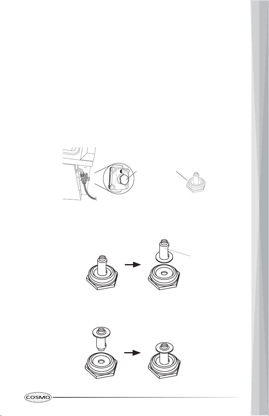
Convert Gas Pressure Regulator
Regulator Cap
1. Turn manual shutoff valve to the closed position.
2. Unplug range or disconnect power.
3. Locate the gas pressure regulator on the back of the range.
IMPORTANT: Do not remove the gas pressure regulator.
4. Unscrew the regulator cap with the wrench.
5. Remove the retainer pin that is currently positioned for use with natural
gas.
6. Turn the retainer pin upside down and place it back into the regular cap.
The regular cap is now positioned for use with LP gas.
Propane gas
position
Retainer Pin
Natural gas
position
32
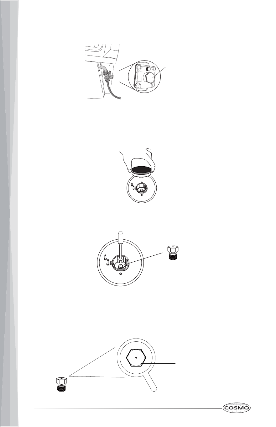
Convert Surface Burners
Regulator
Cap
7. Screw and tighten the regulator cap back into the gas pressure regulator
with the wrench.
1. If installed, remove the burner grates.
2. Remove the burner grates, burner caps, and the burner base.
3. Remove the natural gas orifices with a 9/32" (7 mm) nut driver.
4. Replace the natural gas orifices with the correct LP gas orifices from the
LP conversion kits. LP gas orifices are stamped with a size. Refer to the
following chart for correct LP gas orifice ratings and sizes for proper
placement.
Orifice Size
(091 - Denotes 0.91 mm)
091
Orifice
33
A. Triple Ring (X-Large)
B. Rapid (Large)
C. Semi Rapid (Medium)
D. Auxiliary (Small)
Burner cap
Burner base
Igniter
Flame failure safety device
(for older versions)
Orifice Chart for Surface and Oven Burners: COS-305AGC
Burner Placement
Orifice
Type
Orifice
Size (mm)
Burner
Rating
Triple
Ring
Front Left
NG 2.10 18,000 BTU
LP 1.22 17,000 BTU
Rapid Front Right
NG 1.45
8,800 BTU
LP 0.91
Semi
Rapid
Center
NG 1.29
6,900 BTU
LP 0.80
Semi
Rapid
Rear Left
NG 1.29
6,900 BTU
LP 0.80
Auxiliary Rear Right
NG 1.05
5,000 BTU
LP 0.70
Broil Oven Top
NG 1.40
8,500 BTU
LP 0.83
Bake
Oven
Bottom
NG 1.85
14,000 BTU
LP 1.10
5. Keep and store natural gas orifices in case of re-installation with natural
gas.
6. Replace the burner base, the burner caps, and the burner grates.
C D
C
A B
34
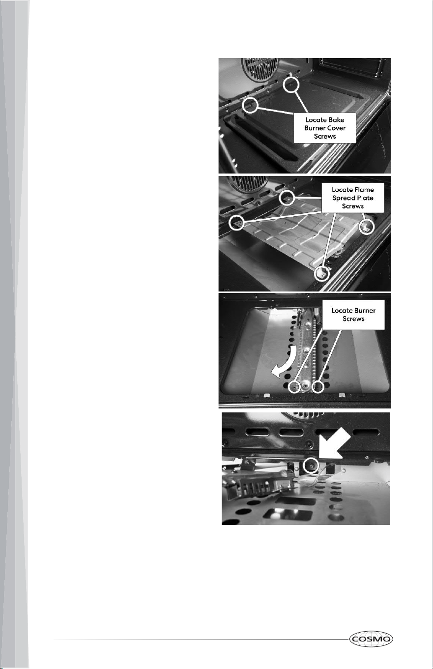
Convert Oven Bake Burner
1. Remove Bake Burner Cover
Open your oven door and
unscrew the back two screws of
bake burner cover. Remove the
bake burner cover.
2. Remove Flame Spread Plate
Unscrew the four screws of the
flame spread plate. Remove the
flame spread plate.
3. Slide Out Burner
Unscrew the front two screws
holding the burner in place. Slide
out the burner up and towards
oven door out of the socket,
careful not to sever or pull on the
wire.
4. Change the Burner Orifice
Move the burner carefully to gain
access to the burner orifice,
careful not to sever or pull on the
wire. Proceed with changing the
orifice.
35
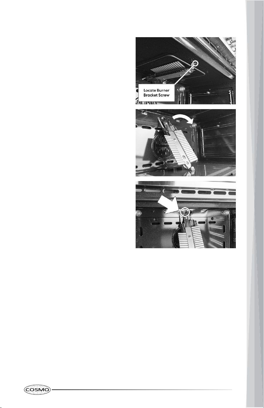
Convert Oven Broil Burner
1. Unscrew Front Bracket
Locate the bracket at the front of
the broiler. Remove the screw.
2. Remove the Burner
Carefully slide the burner forward
and out of the socket, without
severing or damaging the wire
attached. Carefully lay the
burner down as shown in the
image to the right.
3. Change the Burner Orifice
With the burner out of the way
look for the orifice as shown.
Continue with changing the
orifice.
Complete Gas Conversion
1. Open shutoff valve in the gas supply line.
2. Plug in cooktop or reconnect power.
• Refer to "Gas Connection" section in the "Installation Instructions" section
for proper connection of the range to the gas supply.
• Refer to "Complete Installation" section to complete this procedure.
• Refer to the "Adjust Flame Height" section for burner flame adjustments.
IMPORTANT: You may have to adjust the low setting for each cooktop
burner.
36
IMPORTANT
Do Not Return This Product To The Store
If you have a problem with this product, please contact COSMO Customer
Support at
+1 (888) 784-3108
DATED PROOF OF PURCHASE, MODEL #, AND SERIAL # REQUIRED FOR
WARRANTY SERVICE.
IMPORTANT
Ne pas Réexpédier ce Produit au Magasin
Pour tout problème concernant ce produit, veuillez contacter le service des
consommateurs Cosmo Customer Support au
+1 (888) 784-3108
UNE PREUVE D’ACHAT DATEE EST REQUISE POUR BENEFICIER DE LA GARANTIE.
IMPORTANTE
No regrese este producto a la tienda
Si tiene algún problema con este producto, por favor contacte el ayuda al
cliente COSMO al
+1 (888) 784-3108
(Válido solo en E.U.A.)
NECESITA UNA PRUEBA DE DE COMPRA FECHADA, NÚMERO DE MODELO Y DE
SERIE PARA EL SERVICIO DE LA GARANTÍA.
Correct Disposal of this product:
This marking indicates that this appliance should not
be disposed with other household wastes. To prevent
possible harm to the environment or human health
from uncontrolled waste disposal, recycle it responsibly
to promote the sustainable reuse of material resources.
MEMO
MEMO


Cosmo is constantly making efforts to improve the quality and
performance of our products, so we may make changes to our
appliances without updating this manual.
Electronic version of this manual is available at:
www.cosmoappliances.com
APPLIANCES