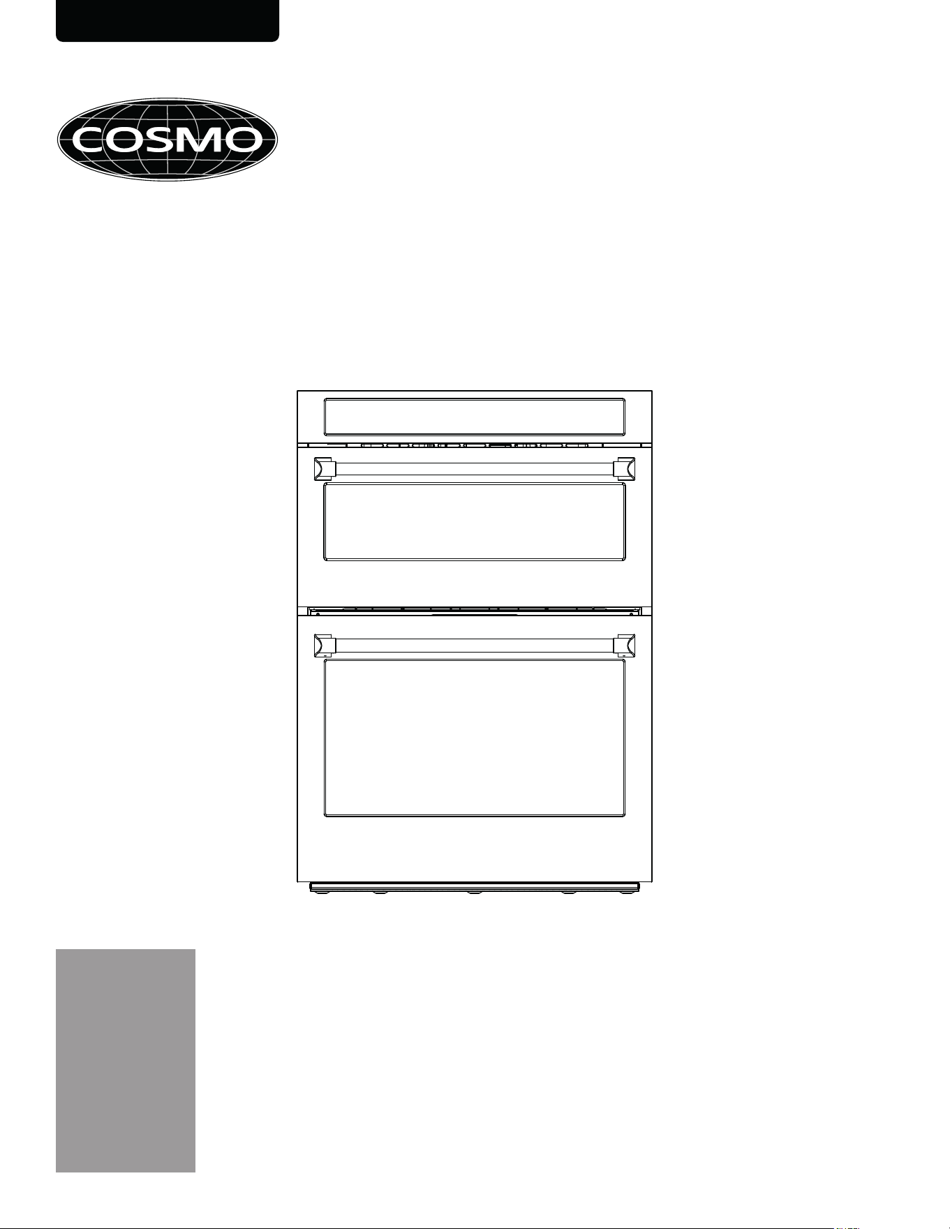
INSTALLATION INSTRUCTIONS
WALL OVEN & MICROWA VE
COMBINATION
COS-WOMCR302SS
OWNER: PLEASE RETAIN THESE INSTRUCTIONS FOR FUTURE REFERENCE.
FOR RESIDENTIAL USE ONLY.
INSTALLER: PLEASE LEAVE THESE INSTRUCTIONS WITH THIS UNIT FOR THE OWNER.
IMPORTANT: READ AND SAVE THESE INSTRUCTIONS.
Rev.26.02
2
THANK YOU FOR YOUR PURCHASE
We know that you have many brands and products to choose from and we are honored to know
that you have decided to take one of our products into your home and hope that you enjoy it.
COSMO Appliances are designed according to the strictest safety and performance standard for
the North American market. We follow the most advanced manufacturing philosophy. Each
appliance leaves the factory after thorough quality inspection and testing. Our distributors and our
service partners are ready to answer any questions you may have regarding how to install, use and
care for your products. We hope that this manual will help you learn to use the product in the safest
and most effective manner.
Before using this product, please read through this manual carefully. Keep this manual in a safe
place for future reference. Please ensure that other persons using this product are familiar with these
instructions as well.
If you have any questions or concerns, please contact the dealer from whom you purchased the
product, or contact our Customer Support at:
1-888-784-3108
Reach us online at:
www.cosmoappliances.com

3
B
uilt-in Combination Oven Safety ................................................................................................................................. 4
Important Safety Instructions ....................................................................................................................................................... 5
Installation Requirements .............................................................................................................................................. 6
Tools and Parts ................................................................................................................................................................................ 6
Location Requirements .................................................................................................................................................................. 9
Product Dimensions ...................................................................................................................................................................... 10
Cabinet/Cutout Dimensions ........................................................................................................................................................ 11
Electrical Requirements.................................................................................................................................................................13
Installation Instructions ................................................................................................................................................ 16
Prepare the Opening .................................................................................................................................................................... 16
Unpack and Prepare Combination Oven ................................................................................................................................. 16
Remove/Install Gliding Oven Racks ...........................................................................................................................................18
Remove/Replace Oven Door ...................................................................................................................................................... 19
Install/Remove Oven Door Handle ............................................................................................................................................ 21
Make Electrical Connection ........................................................................................................................................................ 24
Connecting the Flexible Conduit ......................................................................................................................................... 24
4-Wire Connection ................................................................................................................................................................ 26
3-Wire Connection ................................................................................................................................................................. 27
Install Combination Oven ........................................................................................................................................................... 28
Complete Installation ....................................................................................................................................................................31
Test the Combination Oven Before Use .............................................................................................................................31
TABLE OF CONTENTS
4
BUILT-IN COMBINATION OVEN SAFETY
Your safety and the safety of others are very important.
We have provided many important safety messages in this manual and on your appliance. Always read and obey all
safety messages.
CAUTION
• This is the safety alert symbol.
• This symbol alerts you to potential hazards that can kill or hurt you and others. All safety messages will
follow the safety alert symbol and either the word WARNING or CAUTION.
• You can be killed or seriously injured if you do not follow instructions.
• You may be injured or cause damage to the product if you do not follow instructions.
Precautions to Avoid Possible Exposure to Excessive Microwave Energy
All safety messages will tell you what the potential hazard is, tell you how to reduce the chance of injury, and tell you
what can happen if the instructions are not followed.
• Do not attempt to operate this oven with the door open since open-door operation can result in harmful
exposure to microwave energy. It is important not to defeat or tamper with the safety interlocks.
• Do not place any object between the oven front face and the door or allow soil or cleaner residue to
accumulate on sealing surfaces.
• Do not operate the oven if it is damaged. It is particularly important that the oven door close properly and
that there is no damage to the:
- door (bent),
- hinges and latches (broken or loosened),
- door seals and sealing surfaces.
• The oven should not be adjusted or repaired by anyone except properly qualified service personnel.
WARNING
5
IMPORTANT SAFETY INSTRUCTIONS
Read all instructions carefully before installation.
WARNING
To reduce the risk of fire, explosion, death, electric shock, injury or scalding to persons when using the appliance,
follow basic precautions, including the following:
Installation
• Never allow anyone to climb, sit, stand or hang on the oven door. Injury might result from contact with hot
food or the oven itself.
• Do not line the oven walls, racks, bottom, or any other part of the oven with aluminum foil or any other
material. Doing so will disrupt heat distribution, produce poor baking results and cause permanent damage
to the oven interior. (Aluminum foil will melt on the interior surface of the oven.)
• Do not use aluminum foil or any other material to line the oven bottom. Improper installation of oven liners
may result in a risk of electric shock or fire.
• Make sure your appliance is properly installed and grounded by a qualified installer, according to the
installation instructions. Any adjustment and service should be performed only by qualified installers or
service technicians.
• Be certain that all packing materials are removed from the appliance before operating. Keep plastic,
clothes, paper, and other flammable materials away from parts of the appliance that may become hot.
• The electrical power must be shut off while the electrical connections are being made.
• Improper connection of aluminum house wiring to copper leads can result in an electrical hazard or fire. Use
only connectors designed for joining copper to aluminum and follow the manufacturer’s recommended
procedure closely.
• This appliance is intended for normal residential use. It is not approved for commercial use, outdoor
installation, or any other application not specifically allowed by this manual.
• Flexible conduit from the appliance should be connected directly (hard-wired) to an approved junction box.
A plug or receptacle is NOT permitted on all built-in electric wall ovens.
• This appliance requires a single-phase, 208 VAC or 240 VAC, 60 Hz grounded electrical source dedicated to
the appliance. When installed, appliance must be electrically grounded in accordance with local codes or,
in the absence of local codes, with the National Electrical Code, ANSI/NFPA 70 or the Canadian Electric
Code, CSA C22.1-02.
• Proper installation is the responsibility of the installer. Any adjustment and service should be performed only
by qualified oven installers or service technicians. The manufacturer is not responsible for any injury or
damage that may result from incorrect or defective installation by unauthorized personnel.
• Product failure due to improper installation is not covered under warranty.
• Do not use a steam cleaner to clean the appliance.
• This appliance is not intended to be operated with separate remote control system.
READ AND SAVE THESE INSTRUCTIONS
6
INSTALLATION REQUIREMENTS
TOOLS AND PARTS
Gather the required tools and parts before starting installation. Read and follow the instructions provided with any
tools listed here.
TOOLS NEEDED
PARTS NEEDED
• Phillips screwdriver
• Flat-blade screwdriver
• Hand or electric drill
• Drill bit
• Measuring tape
• Level
• Safety glasses
• Gloves
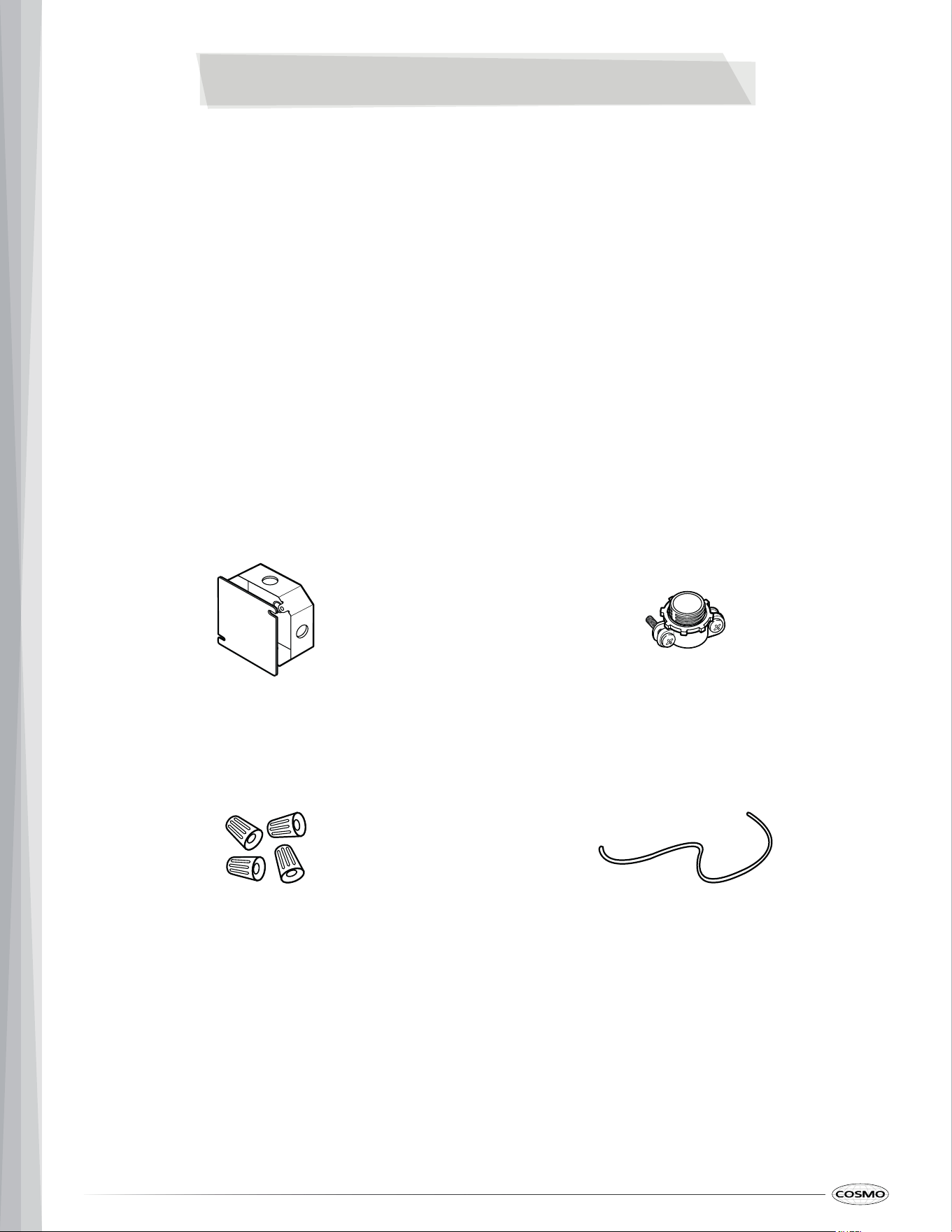
Junction box
Conduit connector
(UL listed or CSA approved)
36" (91 cm) of string Wire connectors
(UL listed or CSA approved)
7
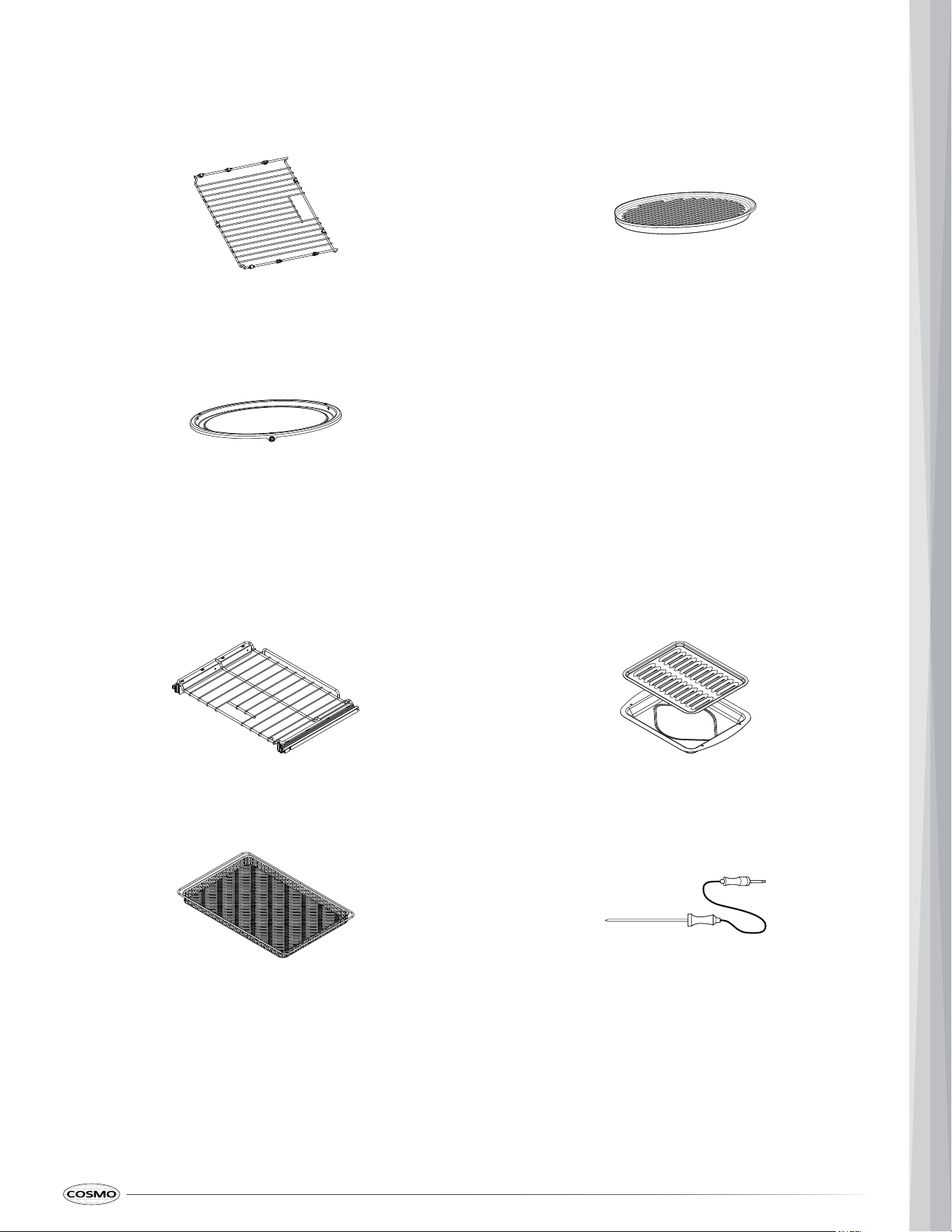
PARTS SUPPLIED
UPPER OVEN
Oven rack Ceramic tray
Metal turntable
LOWER OVEN
Gliding oven rack (2) 2-piece broiler pan
Air fry tray Meat probe
8
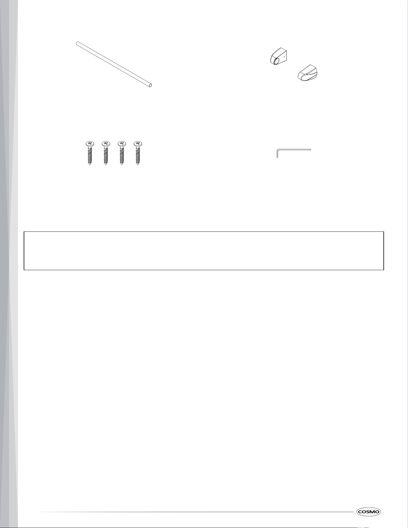
INSTALLATION HARDWARE
Oven door handle (2) Door handle end caps (4)
Hex key 4 x 14 mm wood mounting screws (4 + 2 spare)
Note:
• To purchase these replacement parts or any other accessories, please visit www.cosmoappliances.com or
refer to the contact information referenced at the end of this manual.
9
CAUTION
LOCATION REQUIREMENTS
IMPORTANT: Observe all governing codes and ordinances.
• If marks, blemishes or the cutout opening are visible above the installed appliance, it may be necessary t o
add wood shims under the runners and front trim until the marks or opening are covered.
• If the cabinet does not have a front frame and the sides are less than 3/4" (1.9 cm) thick, shim both sides
equally to establish the cutout width.
• The junction box a must be flush with the conduit opening of the cabinet.
• Grounded electrical supply is required. See "Electrical Requirements" section.
• Allow at least a 23" (58.4 cm) clearance for the oven door depth when it is open.
• The cabinet base platform must be able to support 243 lbs (110 kg) for this appliance plus food load of 4 5
lbs (20 kg). If the cabinet does not have a solid bottom, two braces or runners must be installed level wit h
the bottom of the cutout to support the weight of the appliance. Make sure the base is level and the front o f
the cabinet is square. If the cabinet base is not level, the oven racks will tend to slide out when opening t he
door.
• Check with your builder or cabinet supplier to make sure the materials used on the cabinets and wall
coverings around the oven can withstand the temperature up to 194°F (90°C) generated by the ove n.
Discoloration, delamination or melting may occur.
• Kitchen cabinets in contact with the oven must be heat resistant up to 194°F (90°C), and fronts of near by
units up to at least 158°F (70°C).
• DO NOT remove spacers on the side walls of the built-in oven. These spacers center the oven in the spac e
provided. The oven must be centered to prevent excess heat buildup that may result in heat damage or fire.
• The information in this manual should be followed exactly. Failure to do so could result in fire or electrica l
shock, causing property damage, personal injury or death.
• Be sure the oven is securely installed in a cabinet that is firmly attached to the house structure.
• DO NOT put any weight on the oven door. Never allow anyone to climb, sit, stand or hang on the ove n
door. Weight on the oven door could cause the oven to tip and result in injury from contact with hot food or
the oven itself.
• DO NOT block the oven air exhaust located at the bottom of the oven. Blocking the exhaust may caus e
cabinet damage and product malfunction.
10
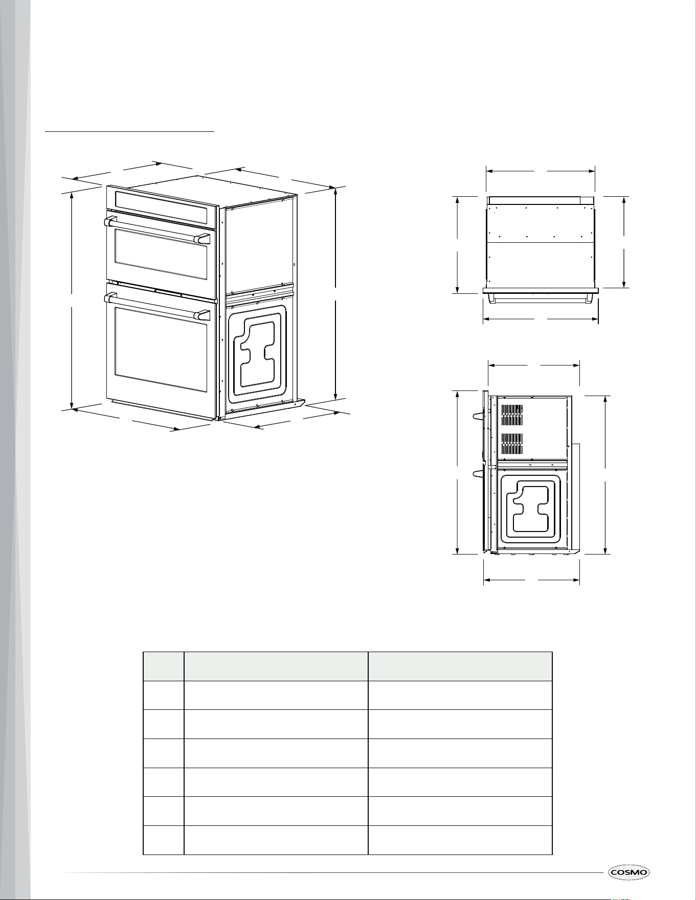
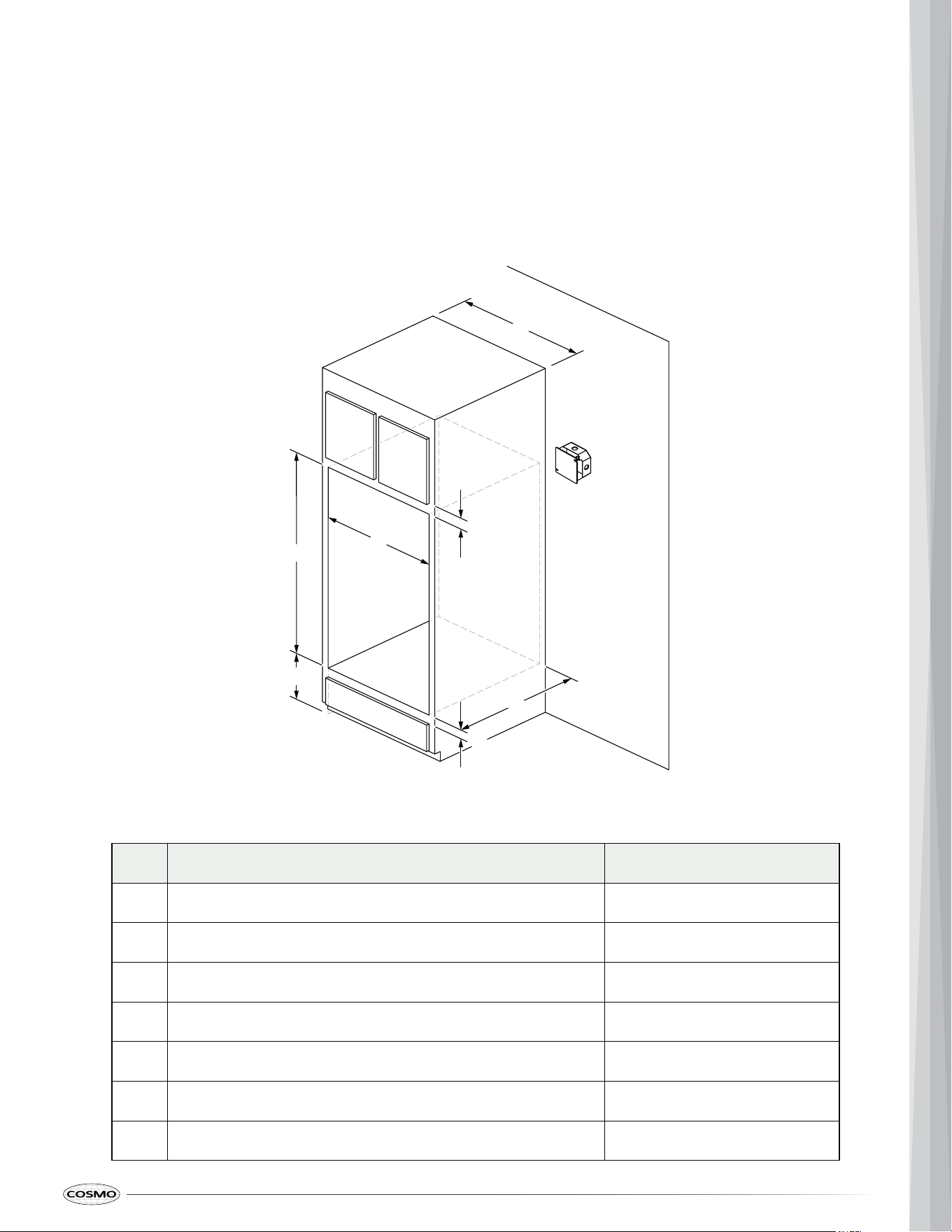
PRODUCT DIMENSIONS
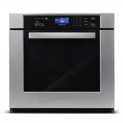
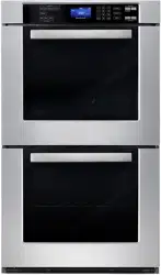
Your model may appear different from the model depicted. Dimensions given are maximum dimensions.
30" Model: COS-WOMCR302SS
Label Description Dimension
A Overall width 30" (76.2 cm)
B
Overall depth 25 ¹⁄₈" (63.8 cm)
C
Overall height 42 ¹⁄₂" (108.0 cm)
D Recessed width 28 ⁵⁄₁₆" (71.9 cm)
E
Recessed depth 23 ³⁄₄" (60.4 cm)
F
Recessed height 41 ¹⁄₄" (104.8 cm)
D
B
E
C
A
F
C
F
E
B
Side
View
D
A
C
F
Top
View
11
Label Description Dimension
A
B
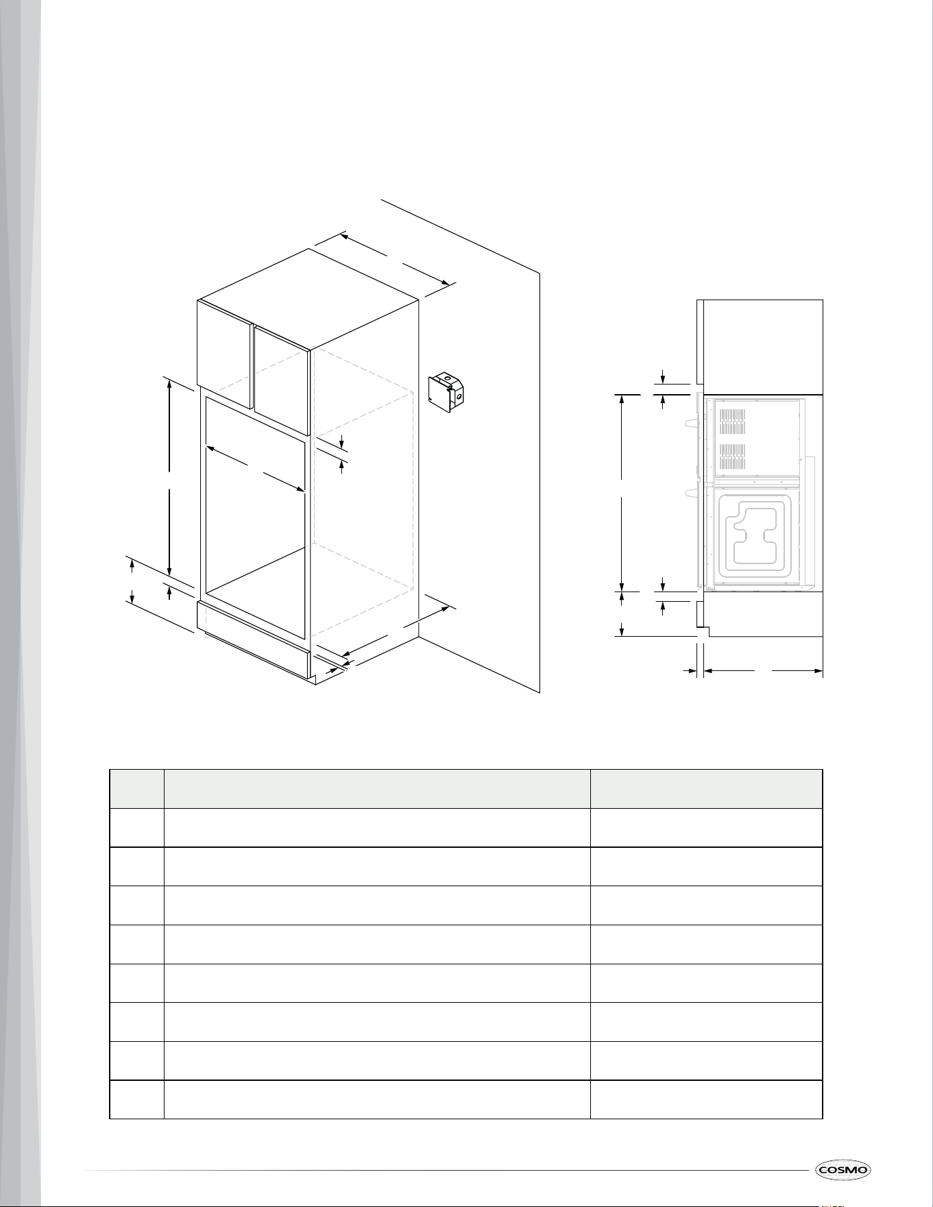
CABINET/CUTOUT DIMENSIONS
Measure the current cutout dimensions and compare them to the cutout dimensions shown below. Little or no
cabinet work may be necessary.
Given dimensions are minimum clearances.
STANDARD INSTALLATION
C
D
E
F
G
Cabinet width 30" (76.2 cm)
1" (2.5 cm)Top of cutout to bottom of upper cabinet door
Cutout width 28 ¹⁄₂" (72.4 cm)
Cutout height 41 ³⁄₄" (106.0 cm)
Cutout depth 22 ¹⁄₁₆" (61.0 cm)
Bottom of cutout to top of lower cabinet door 1 ¹⁄₂" (3.8 cm)
7 ¹⁄₂" - 15 ¹³⁄₁₆" (19.1 - 40.1 cm)Recommended bottom of cutout to floor
F
G
E
D
C
B
A
12
Label Dimensions Measurements
FLUSH INSTALLATION
A 25 ⁷⁄₁₆" (64.6 cm) minimum cabinet depth is required.
The front face of the cleats and platform will be visible and should be treated as a finished surface.
Cleats must be recessed 1 ³⁄₈" (3.6 cm) from the front of the cabinet.
A
B
C
D
E
F
G
H
B
A
E
G
F
H
D
C
Flush inset Cutout width 30 ¹⁄₄" (76.8 cm)
1" (2.5 cm)Top cleat (spacer) height
Cutout width 28 ¹⁄₂" (72.4 cm)
Cutout height
Cutout depth 22 ¹⁄₁₆" (61.0 cm)
Cleat (spacer) inset from front of cabinet 1 ³⁄₈" (3.6 cm)
Recommended bottom cleat (spacer) clearance ³⁄₄" (1.9 cm)
Recommended bottom of cutout to floor 7 ¹⁄₂" - 15 ¹³⁄₁₆" (19.1 - 40.1 cm)
41 ³⁄₄" (106.0 cm)
F
E
G
H
D
B
Side View
13
ELECTRICAL REQUIREMENTS
WARNING
Electrical Shock Hazard
• This appliance must be properly grounded.
• Do not use an extension cord with this appliance.
• Remove house fuse or open circuit breaker before beginning installation.
• Failure to do so could result in death, fire, or electrical shock.
If codes permit and a separate ground wire is used, it is recommended that a qualified electrical installer determine
that the ground path and the wire gauge are in accordance with local codes.
Check with a qualified electrical installer if you are not sure the oven is properly grounded. This oven must be
connected to a grounded metal, permanent wiring system.
Be sure that the electrical connection and wire size are adequate and in conformance with the National Electrical
Code, ANSI/NFPA 70-latest edition or CSA Standards C22.1-94, Canadian Electrical Code, Part 1 and C22.2 No. O-
M91-latest edition, and all local codes and ordinances.
A copy of the above code standards can be obtained from:
National Fire Protection Association
1 Batterymarch Park
Quincy, MA 02169-7471
CSA International
8501 East Pleasant Valley Road
Cleveland, OH 44131-5575
ELECTRICAL CONNECTION
Check with your local utilities for electrical codes which apply in your area. Failure to wire your oven according to
governing codes could result in a hazardous condition.
We recommend you have the electrical wiring and hookup of your appliance connected by a qualified electrician.
After installation, have the electrician show you how to disconnect power from the appliance.
To properly install your appliance, you must determine the type of electrical connection you will be using and follow
the instructions provided for it here.
14
• Appliance must be supplied with the proper electrical voltage, amperage, and frequency as specified on the
model/serial/rating plate.
• This appliance requires a single-phase, 208 VAC or 240 VAC, 60 Hz electrical system dedicated to the
appliance. It is the personal responsibility of the owner to provide the correct electrical service for this
appliance.
• This appliance must be connected to an individual (dedicated to the appliance), properly grounded branch
circuit, protected by a circuit breaker or fuse.
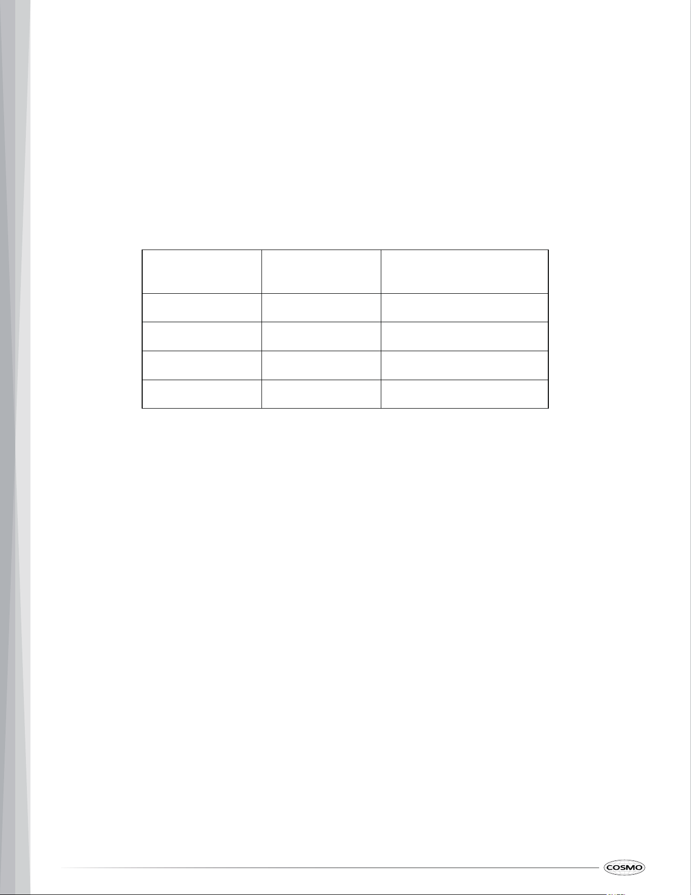
• Use the chart below to determine the minimum recommended dedicated circuit protection:
Rating at 240 V Rating at 208 V
Recommended Circuit Size
(Dedicated)
≤ 4.8 kW ≤ 4.2 kW 20 Amp
4.9 – 7.2 kW 4.3 – 6.2 kW 30 Amp
7.3 – 9.6 kW 6.3 – 8.3 kW 40 Amp
9.7 – 12.0 kW 8.4 – 10.4 kW 50 Amp
• The appliance, when installed, must be electrically grounded in accordance with local codes, or in the
absence of local codes, with the National Electrical Code, ANSI/NFPA 70 or the Canadian Electrical Code,
CSA C22.1-02. In Canada, the appliance must be electrically grounded in accordance with Canadian
Electrical Code. Be sure your appliance is properly installed and grounded by a qualified technician.
• Effective January 1, 1996, the National Electrical Code requires that new construction (not existing) utilize a 4-
conductor connection to an electric oven. When installing an electric oven in new construction, mobile home,
recreational vehicle, or an area where local codes prohibit grounding through the neutral conductor, refer to
the "4-Wire Connection" in the "Make Electrical Connection" section.
• A circuit breaker is recommended.
• Flexible conduit from the oven should be connected directly (hard-wired) to an approved junction box. A plug
or receptacle is NOT permitted on all built-in electric wall ovens.
• The conduit connector must be securely attached to the junction box and the flexible conduit must be
securely attached to the conduit connector. If the flexible conduit will not fit within the conduit connector, do
not install the oven until a connector of the proper size is obtained.
• Do not cut the conduit. The length of conduit provided is for serviceability of the oven.
• A UL listed or CSA approved conduit connector must be provided.

15
• If the house has aluminum wiring, follow the procedure below:
- Connect the aluminum wiring using special connectors and/or tools designed and UL listed for joining
copper to aluminum.
- Follow the electrical connector manufacturer’s recommended procedure. Aluminum/copper
connection must conform with local codes and industry accepted wiring practices.
- Be sure that the electrical connection and wire size are adequate and in conformance with th
e
N
ational Electrical Code, ANSI/ NFPA 70-latest edition or CSA Standards C22.1-94, Canadian
Electrical Code, Part 1 and C22.2 No. O-M91-latest edition, and all local codes and ordinances.
- Check with your local utilities for electrical codes which apply in your area. Failure to wire your
appliance according to governing codes could result in a hazardous condition.
16
INSTALLATION INSTRUCTIONS
IMPORTANT:
PREPARE THE OPENING
installation.
1 . Decide on the final location for the combination oven. Avoid drilling or cutting into house wiring during
• This appliance shall be installed only by authorized persons and in accordance with the manufacturer' s
installation instructions, municipal building codes, and electrical wiring regulations.
• Before beginning the installation, switch power off at the service panel and lock the service disconnectin g
means to prevent power from being switched on accidentally. When the service disconnecting means canno t
be locked, securely fasten a prominent warning device, such as a tag, to the service panel.
WARNING
UNPACK AND PREPARE COMBINATION OVEN
Excessive Weight Hazard
• Use two or more people to move and install or uninstall appliance. Failure to do so can result in back o r
other injury.
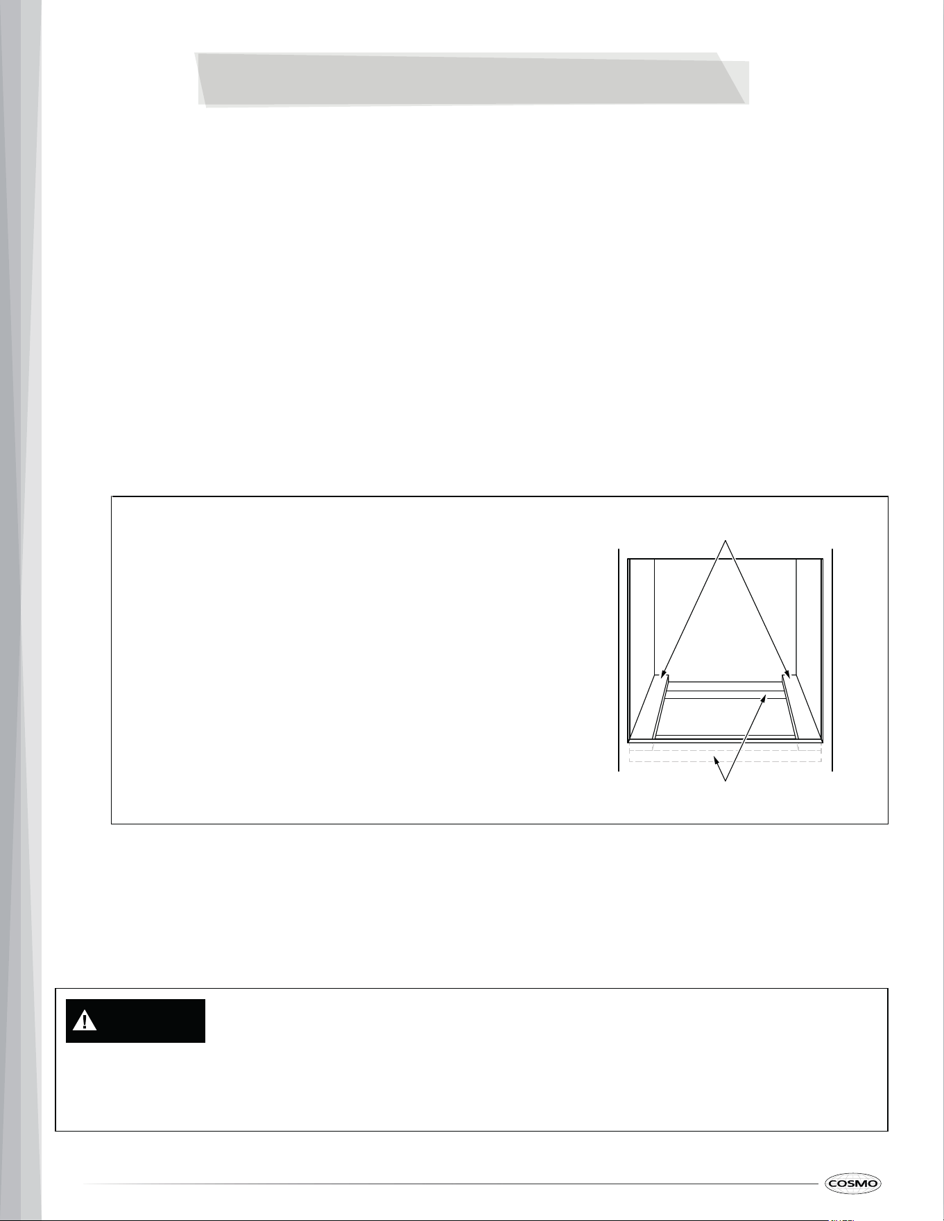
Note:
• If the cabinet does not have a solid bottom,
two braces or runners must be installed to
support the oven weight of 243 lbs (110 kg) plus
food load of 45 lbs (20 kg).
• If marks, blemishes or the cutout opening
are visible above the installed oven, it may
be necessary to add wood shims under the
runners until the marks or opening are
covered.
• If the cabinet does not have a front frame
and the sides are less than ¾" (1.9 cm)
thick, shim both sides equally to establish
the cutout width.
2" x 4" (5 cm x 10 cm) or Equivalent Runners Level with
Bottom of Cutout and Flush with Sides of Cutout
Suitable Bracing to Support Runners
17
IMPORTANT:
• Keep packing materials out of the reach of children. Packaging material can be dangerous for children. There
is a risk of suffocation.
• Do not remove any warning-type labels, the model/serial number label, or the Tech Sheet that is located on
the back of the appliance.
• Do not use oven door handle or any portion of the front frame for lifting or moving.
• Do not push or pull the appliance by grabbing the opened oven door. Doing so can result in serious damage
to the appliance.
• Do not use sharp instruments, rubbing alcohol, flammable fluids, or abrasive cleaners to remove tape or glue.
These products can damage the surface of your appliance.
• To remove any remaining tape or glue, rub the area briskly with your thumb. Tape or glue residue can also be
easily removed by rubbing a small amount of liquid dish soap over the adhesive with your fingers. Wipe with
warm water and dry.
1. To av
oid floor damage, set the combination oven onto cardboard prior to installation.
2. Remove the shipping materials and tape from the oven. Remember to keep the corner posts and other
materials that may be needed for installation.
3. Rem
ove and set aside literature pack, oven racks, air fry tray, and other parts from inside the oven. See
"Remove/Install Gliding Oven Racks" section.
4. Rem
ove the lower oven door. See "Remove/Replace Oven Door" section.
Not
e:
• Door removal is not a requirement for installation of the product but is an added convenience.
5. Usi
ng two or more people, move oven and cardboard close to the oven’s final location.
CAUTION
Laceration, Foreign Object, Crush Hazard
• When installing, moving, or servicing any appliance, wear proper protective equipment, including cu t
resistant gloves, steel-toed shoes, and safety glasses.
18
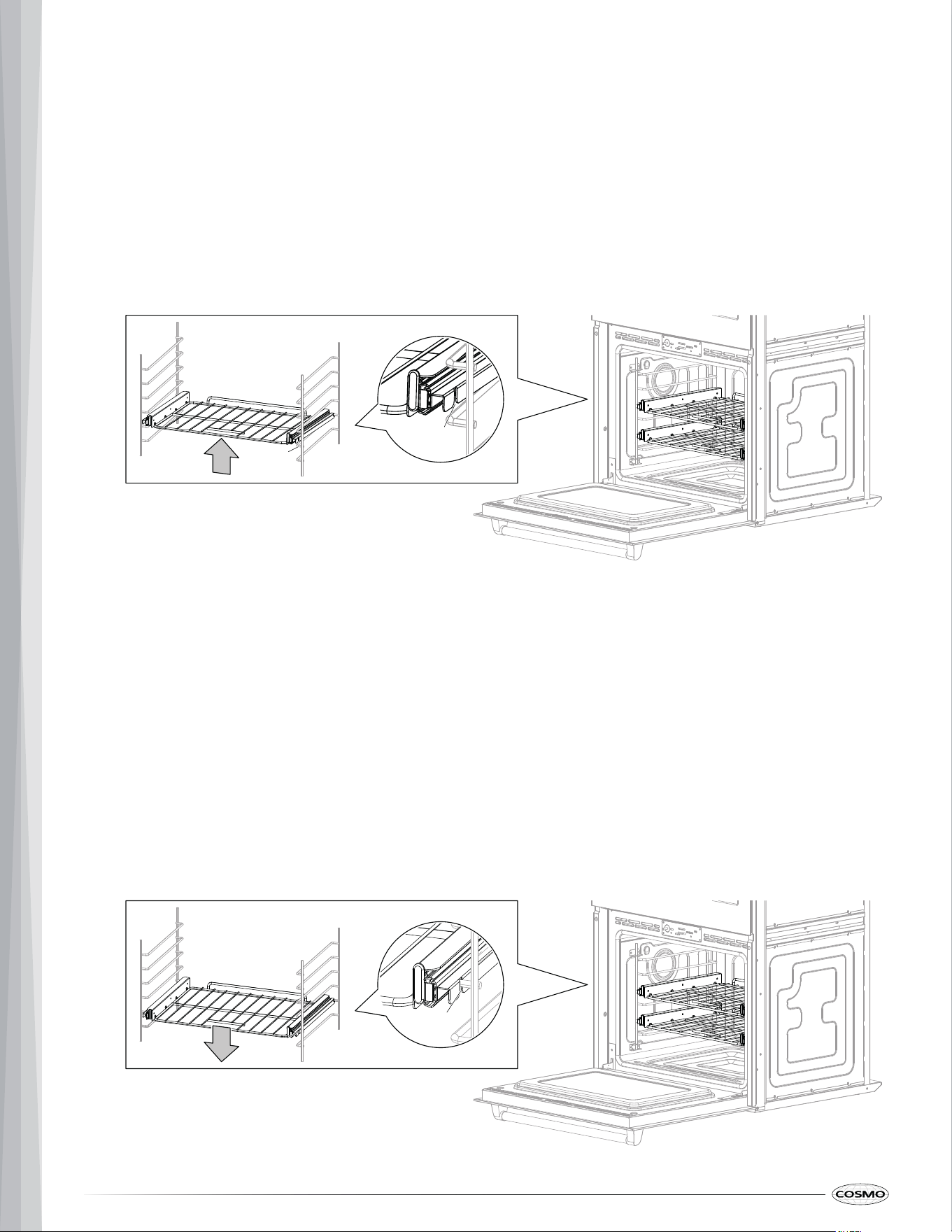
rack guide.
1. With the rack in the closed position, grasp the front of the rack and lift it until the rack stop is free from the
REMOVE/INSTALL GLIDING OVEN RACKS
The gliding racks slide in and out on a frame in lower oven. This keeps heavy cookware level and prevents it from
sliding forward when the rack is completely extended.
REMOVING GLIDING OVEN RACKS
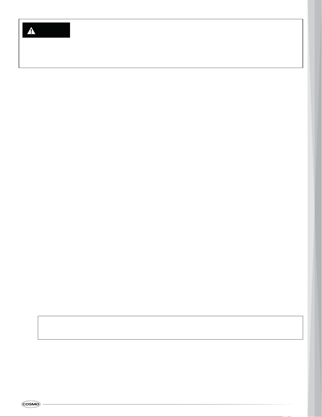
INSTALLING GLIDING OVEN RACKS
2. After disengaging the rack stop, pull and lift the back of the rack out.
1. Start with the rack in the closed position. Hold the rack with both hands on the sides.
2. Insert the rack onto the desired level and slide it along the struts of the level until it stops.
3. Slowly lower the front of the rack. Make sure that the rack stop is engaged with the rack guide.
Rack
guide
Rack
stop
Rack
guide
Rack
stop
19
WARNING
REMOVE/REPLACE OVEN DOOR
For normal use, it is not suggested to remove the oven door. However, if removal is necessary, make sure the oven is
off and cool.
Note:
• The door for the microwave oven on a combination oven should never be removed, unless by a certified
technician.
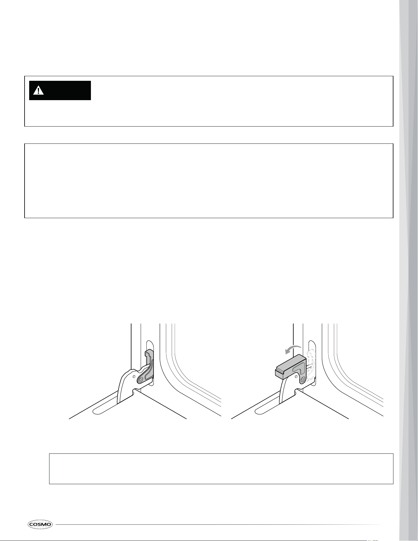
REMOVING LOWER OVEN DOOR
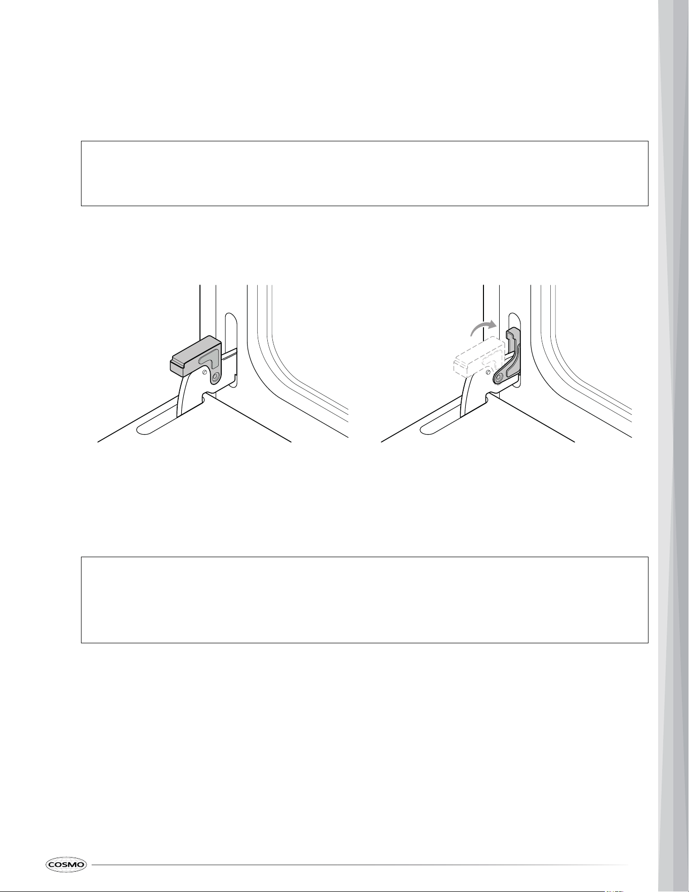
Lock position Unlock position
Note:
1. Fully open the lower oven door.
2. Locate the oven door hinge locks in both corners of the oven door, and rotate the hinge locks as far toward
the open door to the unlock position.
• The oven door is heavy.
• Prior to removing the oven door, prepare a surface where you will place it. This surface should be flat and
covered with a soft blanket, or use the corner posts from your packaging material.
• If oven door is removed, confirm that oven door operates correctly and seals properly when reinstalled. If
door gasket does not seal completely, heat escaping from around doors could ignite cabinetry.
• If the oven door hinge lock is not rotated fully, the oven door will not remove properly.
20
Note:
oven door by door handle, if installed.
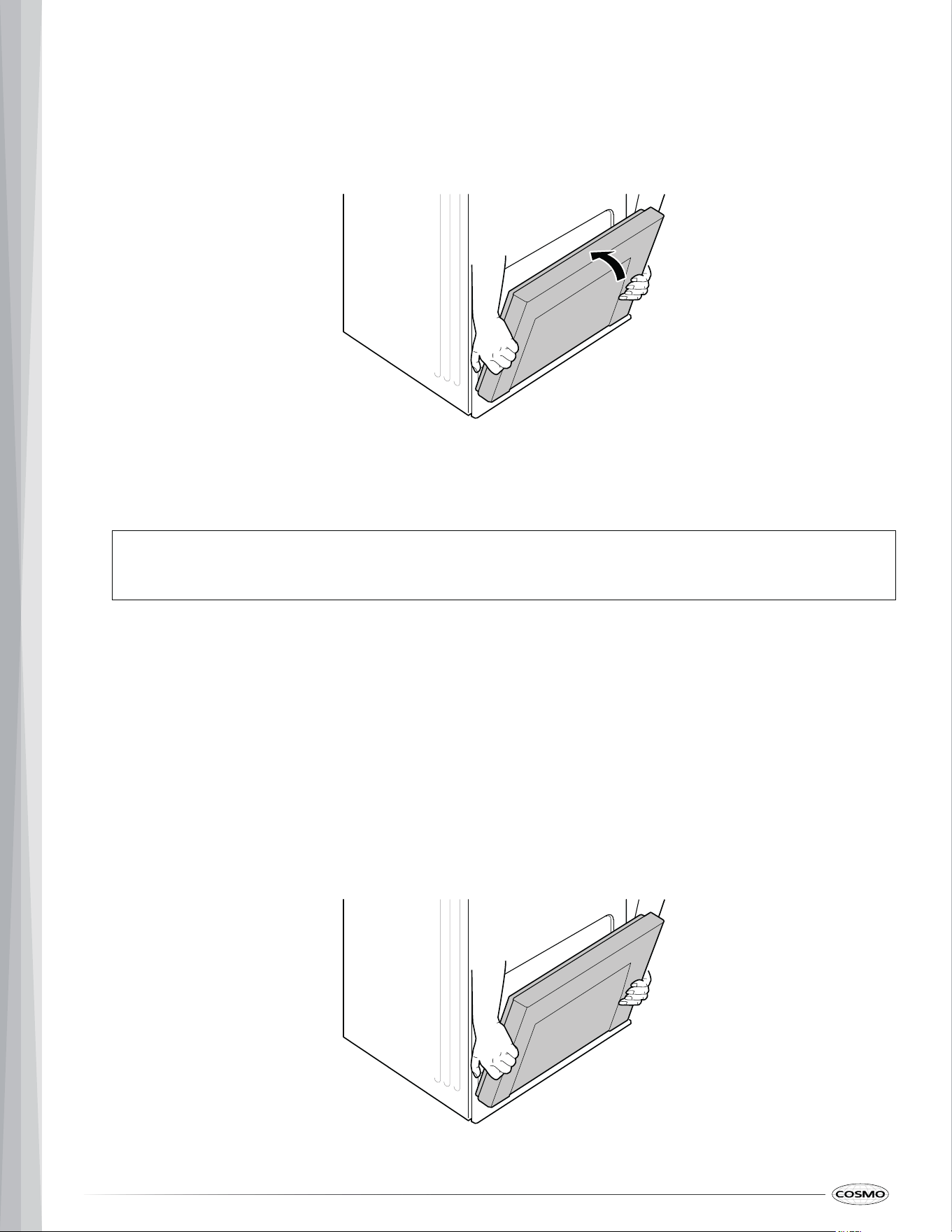
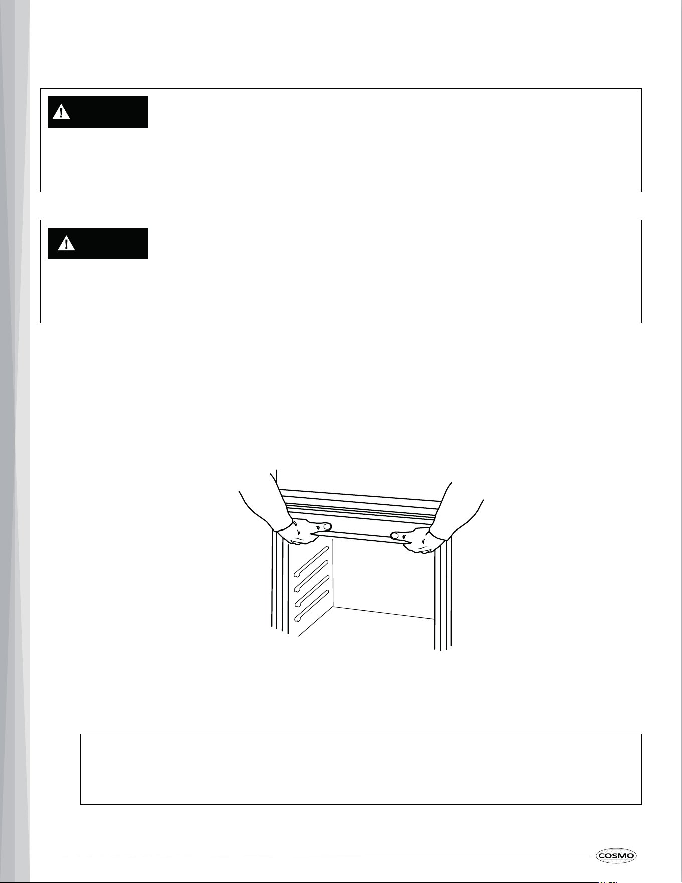
3. Using two hands, firmly grasp both sides of the oven door.
4. Gently close the oven door to the romoval position, which is approximately five degrees or 2" - 3" (5.1 - 7.6 cm)
from being fully closed. If the position is correct, the hinge arms will move freely.
5. Lift oven door up and out until the hinge arms are clear of the slots, and set the oven door aside. Do not lift
REPLACING LOWER OVEN DOOR
• Do not lay the oven door on its handle or front side. This could cause dents or scratches.
1. Locate the slots on each side of the oven cavity for the door hinge locks.
2. Using two hands, firmly grasp both sides of the oven door. Do not lift oven door by door handle, if installed.
3. Hold the oven door at similar angle as the removal position, which is approximately five degrees or 2" - 3" (5.1
- 7.6 cm) from being fully closed
21
Note:
4. Seat the indentation of the hinge arms into the bottom edge of the hinge slots. The notch in the hinge arm s
must be fully seated into the bottom edge of the slots.
5. Gently lower the oven door to the fully open position.
• If the oven door will not open fully, the indentation is not seated correctly in the bottom edge of t he
slots. Repeat the steps above.
oven cavity to the lock position.
Unlock position
6. Locate the oven door hinge locks in the corners of the oven door, and rotate the hinge locks as far toward the
Lock position
while closed.
Note:
7. Gently swing the oven door upward to close. Check that the oven door is free to open and close, and is level
• The oven door should not be forced opened or closed.
• When the hinges are properly installed and the oven door is closed, the oven door should be level. I f
one side of the oven door is lower than the other, the hinge on that side is not properly installed.
• Hex key (provided)
INSTALL/REMOVE OVEN DOOR HANDLE
Be very careful not to scratch the surface of the unit. The appearance of the handle may vary from what is shown
below, but the installation will be the same.
Tool Needed
22
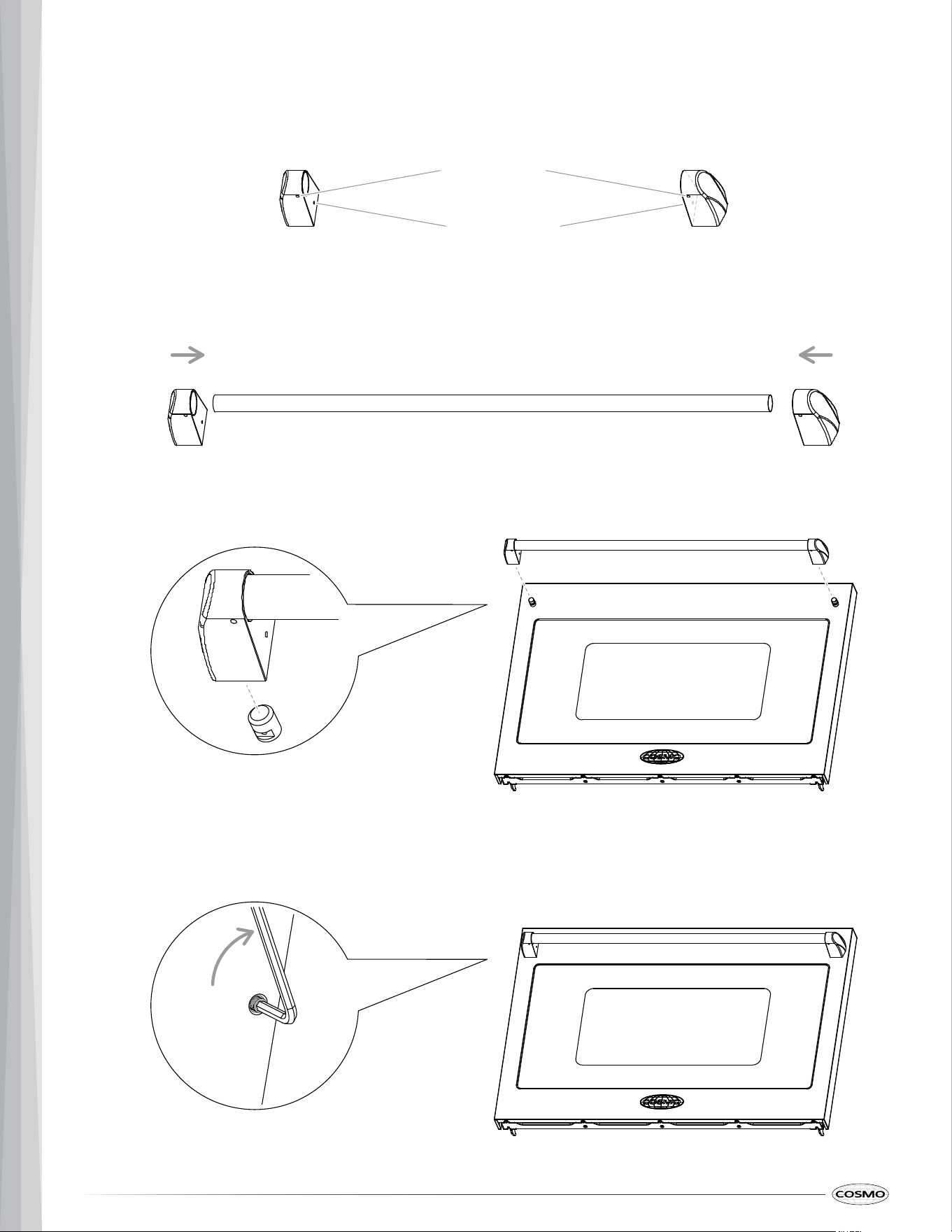
INSTALLING THE HANDLE
1. Partially loosen the set screws in the handle end caps with the Hex key.
2. Attach the end cap over each end of the handle, and slightly tighten the handle set screws.
3. Place the handle on the door by fitting both ends of the handle footprints over the mounting fasteners.
4. Tighten the mounting fastener and handle set screws.
Mounting fastener
set screw
Handle set screw
23
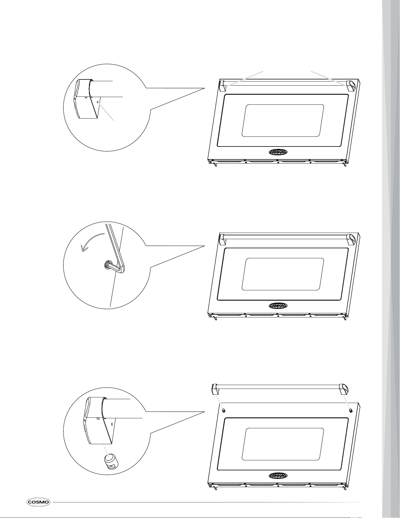
REMOVING THE HANDLE
1. Locate the mounting fastener set screws on the handle end caps.
set screw from the handle end cap.
2.
3. Keep supporting the handle while loosening the set screw on the other handle end cap.
4. Remove the handle from the mounting fasteners on the door and set aside.
Mounting fastener
set screw
Mounting fastener
set screw
24
MAKE ELECTRICAL CONNECTION
WARNING
Electrical Shock Hazard
IMPORTANT:
• Remove house fuse or open circuit breaker to disconnect power before servicing.
• This appliance must be properly grounded.
• Do not use an adapter or an extension cord.
• Failure to do so can result in death, fire, or electrical shock.
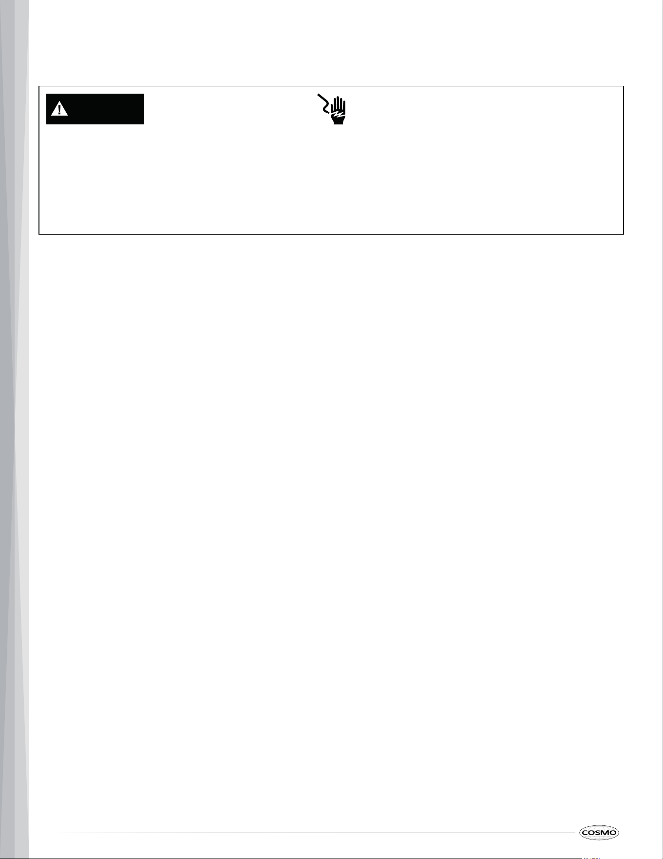
CONNECTING THE FLEXIBLE CONDUIT
This combination oven is manufactured with a neutral (white) power supply wire and a cabinet-connected green (or
bare) ground wire.
1. Disconnect power by turning off the circuit breaker or removing fuses to the combination oven branch circuit.
2. Remove junction box cover, if it is present.
• Installation work and repairs should only be performed by a qualified technician in accordance with all
applicable codes and standards. Repairs and service by unqualified persons could be dangerous and t he
manufacturer will not be held responsible.
• Before connecting the appliance to the power supply, make sure that the voltage and frequency listed on th e
rating label correspond with the household electrical supply. This data must correspond to prevent applianc e
damage. Consult an electrician if in doubt.
• This appliance requires a single-phase, 208 VAC or 240 VAC, 60 Hz electrical system dedicated to th e
appliance. It is the personal responsibility of the owner to provide the correct electrical service for th is
appliance.
• This appliance must be connected to an individual (dedicated to the appliance), properly grounded branc h
circuit, protected by a circuit breaker or fuse.
• Local codes and ordinances take precedence over these instructions. Complete electrical connection s
according to local codes and ordinances.
25
3. Install a UL listed or CSA approved conduit connector to the junction box.
4. With the oven positioned directly in front of the cabinet opening, feed the flexible conduit from the ove n
through the opening in the cabinet.
5. Route the flexible conduit to the junction box through the conduit connector.
6. Tighten screws on conduit connector.
7. Complete installation following instructions for your type of electrical connection from home power supply:
• 4-wire connection (recommended)
• 3-wire connection (if 4-wire is not available)
4-Wire Cable from Power Supply
Junction Box
UL Listed or CSA Approved
Wire Connector
UL Listed or CSA Approved
Conduit Connector
26
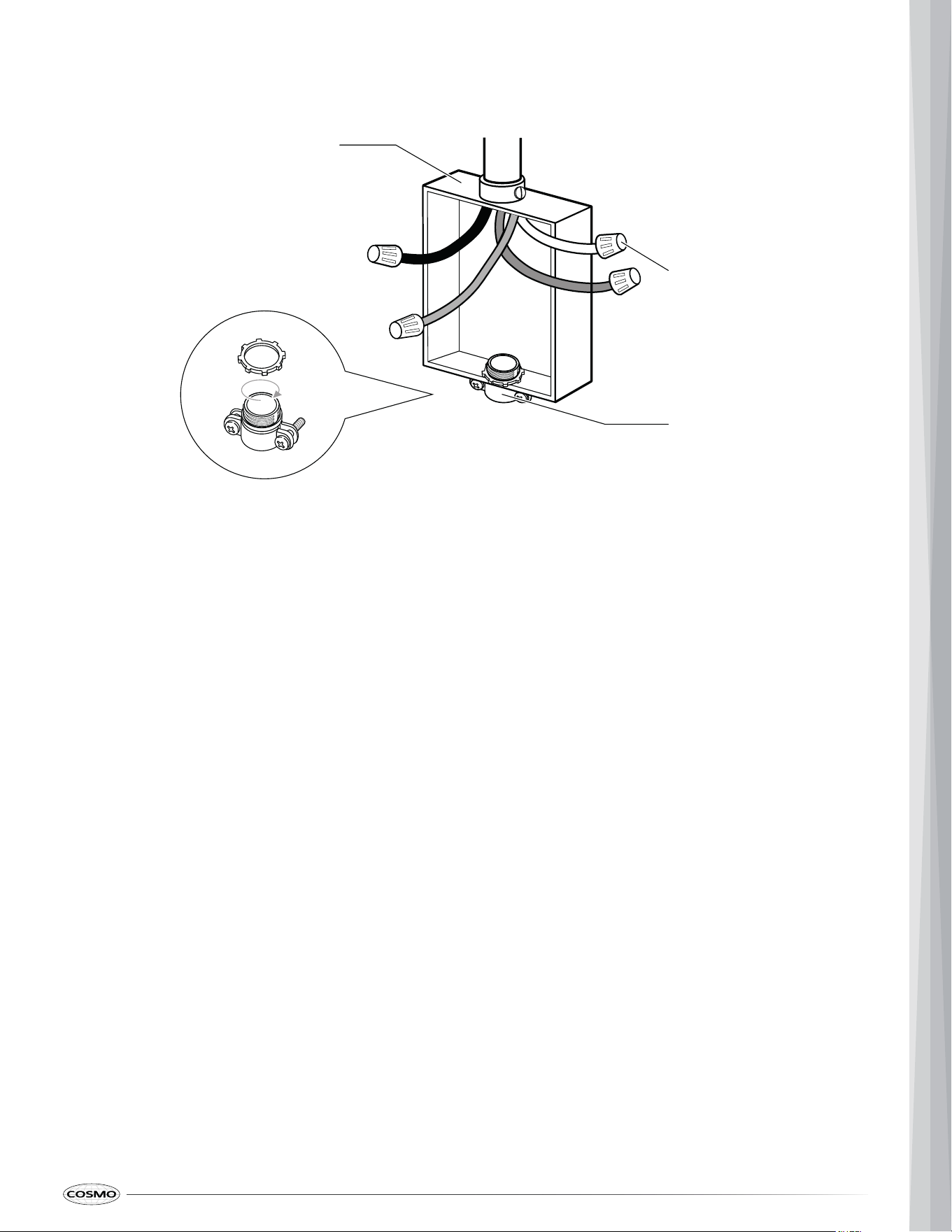
1. Using a UL listed wire connector:
• Connect the two black wires together.
• Connect the two red wires together.
• Connect the two neutral (white) wires together.
• Connect the ground (green or bare) wire from the oven flexible conduit to the ground (green or bare)
wire in the junction box.
2. Replace junction box cover if removed.
4-WIRE CONNECTION
IMPORTANT: Use the 4-wire connection from home power supply in areas where local codes do not allow grounding
through neutral, new branch circuit installations (1996 NEC), mobile homes, recreational vehicles, and new
constructions.
4-Wire Cable from Power Supply
Junction Box
White Wires
UL Listed or CSA Approved
Wire Connector
Red Wires
UL Listed or CSA Approved
Conduit Connector
Oven Conduit
Black Wires
Ground (Green or Bare)
Wires
27
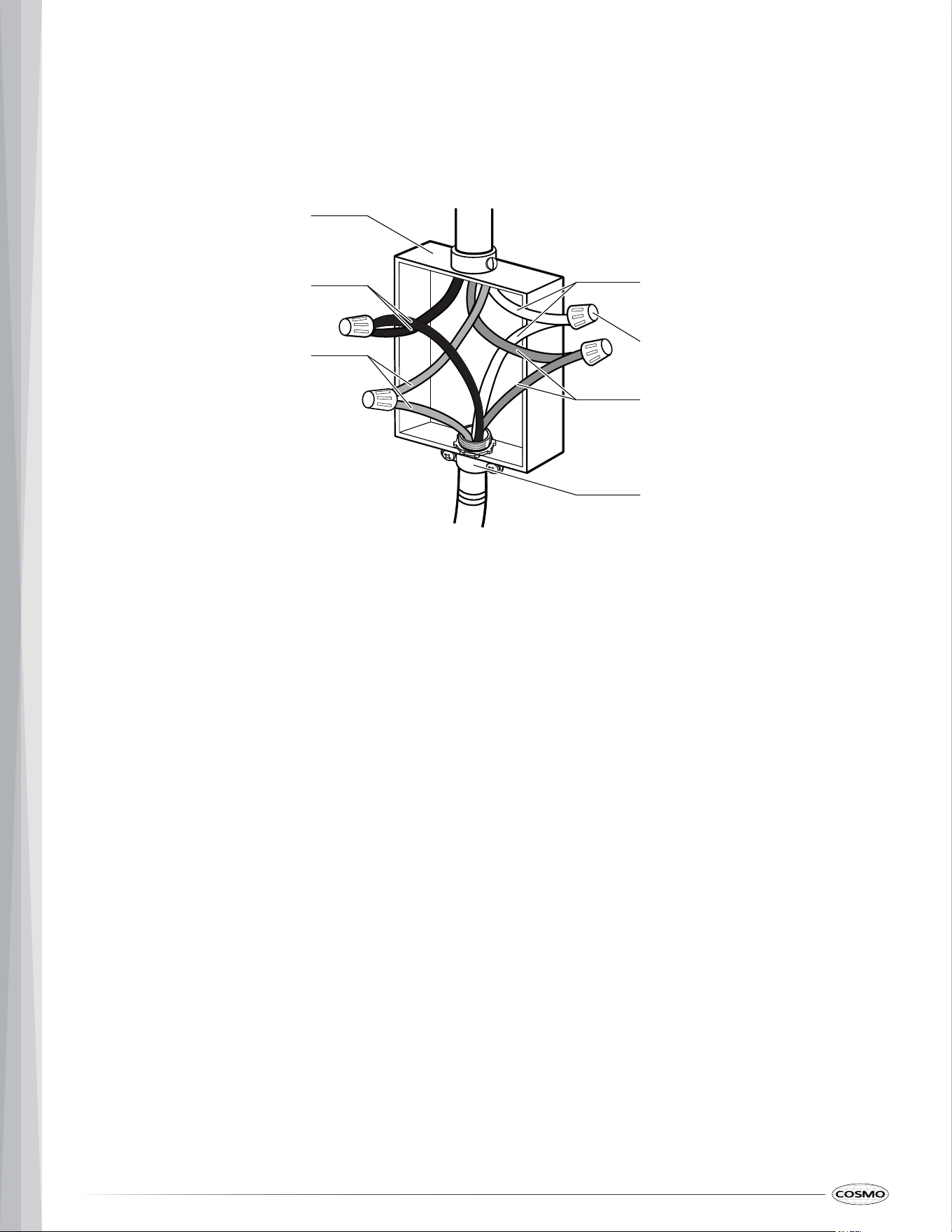
3-WIRE CONNECTION
IMPORTANT: Use the 3-wire connection from home power supply where local codes permit a 3-wire connection.
1. Using a UL listed wire connector:
• Connect the two black wires together.
• Connect the two red wires together.
• Connect the two neutral (white) wires and the ground (green or bare) wire from the oven flexible
conduit together.
2. Replace junction box cover if removed.
3-Wire Cable from Power Supply
Junction Box
UL Listed or CSA Approved
Wire Connector
Red Wires
UL Listed or CSA Approved
Conduit Connector
Oven Conduit
Black Wires
White Wires
Ground (Green or Bare)
Wires
28
INSTALL COMBINATION OVEN
WARNING
Excessive Weight Hazard
CAUTION
• Use two or more people to move and install or uninstall appliance. Failure to do so can result in back or
other injury.
Laceration, Foreign Object, Crush Hazard
• When installing, moving, or servicing any appliance, wear proper protective equipment, including cut
resistant gloves, steel-toed shoes, and safety glasses.
Note:
on the top of the oven in a natural loop.
3. Push the oven into the cabinet. While pushing oven into cabinet, pull the string so that the flexible conduit lies
1. Loop (do not tie) a 36" (91 cm) string around the flexible conduit before the combination oven is slid into
place. Lay the string over the top of the oven and use it to keep the
conduit from falling behind the oven.
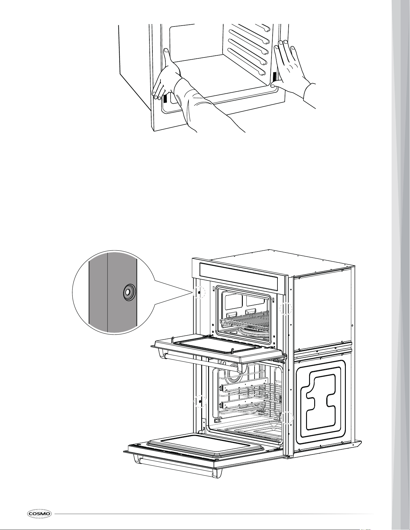
2. Using two or more people, lift oven into cabinet cutout using the oven opening as a grip.
• Carefully push against the lower oven front frame. Do not push against outside edges.
• Ensure that no damage is done to oven gasket which lines the edge of oven cavity.
29
4. When you are sure the flexible conduit is out of the way, carefully push the oven 3/4 way into the cabinet.
Remove the string by pulling on one end of the loop.
5. Carefully push the oven completely into the cabinet until the back surface of the front frame touches the front
wall of the cabinet and center oven in cabinet cutout.
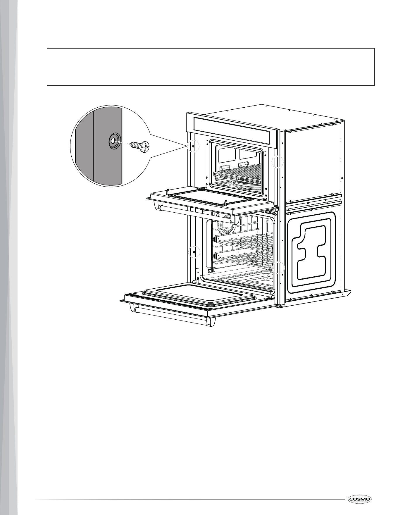
6. Using the mounting holes on the oven side trim as a guide, drill 4 pilot holes (one on each side in both the
upper and lower ovens) for mounting screws provided.
30
Note:
7. Secure the oven to the cabinet with mounting screws provided. Do not overtighten screws.
• If the cabinet is particle board, you must use 3/4" particle board screws. These may be purchased at
any hardware store.
8. Replace the lower oven door, if removed. See "Remove/Replace Oven Door" section.
9. Install the oven door handles. See "Install/Remove Oven Door Handle" section.
31
COMPLETE INSTALLATION
Check that all accessories are present and you have all of your tools.
Note:
• The display panel will light briefly. If it does not, refer the "Warranty" section in the user manual.
1. Install the gliding oven racks. See "Remove/Install Gliding Oven Rack" section.
2. Check that all parts are now installed.
3. Dispose of/recycle all packaging materials.
4. For oven cleaning, read the "Maintenance" section in the user manual.
5. Reconnect power.
Note:
• Ensure all packaging is removed, and oven is empty except for oven rack(s).
• Be sure power is in service.
TEST THE COMBINATION OVEN BEFORE USE
Each of the functions has been factory checked before shipping. However, it is suggested that you verify the
operation of the oven once more. Refer to the user manual. Follow the instructions for the basic check.
IMPORTANT:
• A small amount of smoke and odor may be noticeable during the initial break-in period.

32
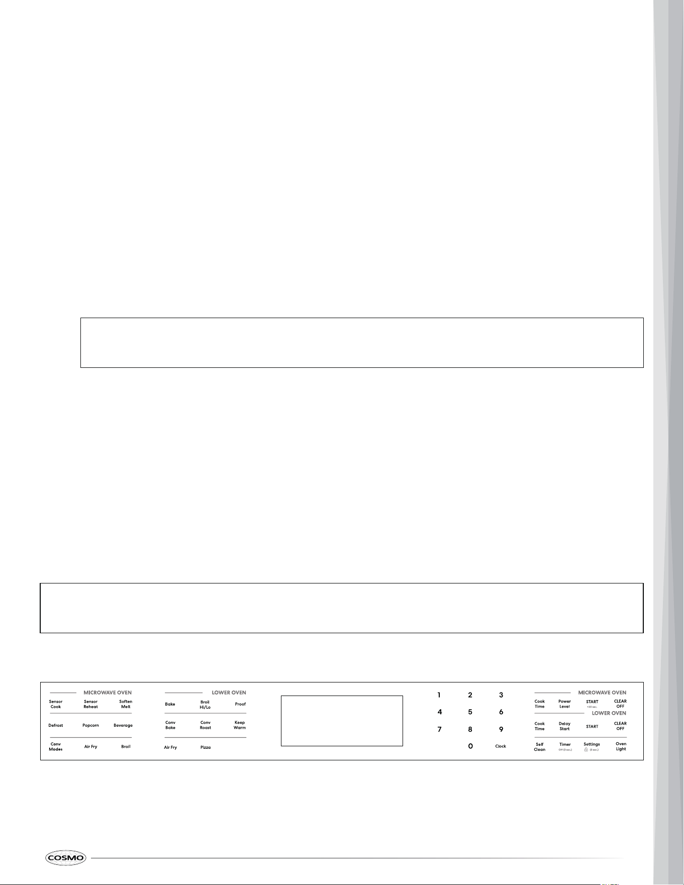
UPPER OVEN
1. Check the operation of the microwave mode.
a) Place a glass bowl filled with water in upper oven.
b) Close the oven door.
c) Press Cook Time (upper oven) to select Microwave mode.
d) Press 1, 0, and 0 to set the cook time to 1 minute.
e) Press START (upper oven) to turn the microwave on.
f) When the cook time is over, inspect the water in glass bowl. The water should be hot.
2. Check the operation of the broil mode.
a) Keep the oven door closed.
b) Press Broil (upper oven) once to select Hi Broil mode.
c) Press START (upper oven) to turn the oven on.
d) When the oven is set to broil, the upper element in the oven should become red.
e) After a few minutes, press CLEAR/OFF (upper oven) to stop Broil mode.
f) Open the oven door. You should feel heat from the oven. If you do not feel heat, contact a qualified
technician.
3. Check the operation of the convection mode.
a) Keep the oven door closed.
b) Press Conv Modes (upper oven) to select Convection modes.
c) Press 1 to select Baked Goods.
d) Press 3, 5, and 0 to enter temperature 350°F (177°C).
e) Press START (upper oven) to turn the oven on.
f) When the oven is set to convection mode, the rear convection fan inside the oven should come on
with the door closed. Confirm that the convection fan is operating.
g) After a few minutes, press CLEAR/OFF (upper oven) to stop the convection mode.
h) Open the oven door. Without touching the oven components, confirm that heat can be felt radiating
from the oven bottom and rear wall. If you do not feel heat, contact a qualified technician.

33
LOWER OVEN
1. Check the operation of the broil mode.
a) Keep the oven door closed.
b) Press Broil (lower oven) once to select Hi Broil mode.
c) Press START (lower oven).
d) When the oven is set to broil, the upper element in the oven should become red.
e) After a few minutes, partially open the oven door. You should feel heat from the oven. If you do not
feel heat, turn off the oven and contact a qualified technician.
f) Press CLEAR/OFF (lower oven) to stop Broil mode.
2. Check the operation of the convection bake mode.
a) Keep the oven door closed.
b) Press Conv Bake (lower oven) to select Convection Bake mode.
c) Press 3, 5, and 0 to enter temperature 350°F (177°C).
d) Press START. The oven starts to preheat.
e) When the oven is set to convection bake, the rear convection fan inside the oven should come on with
the door closed. Confirm that the convection fan is operating.
f) After a few minutes, open the oven door temporarily. Without touching the oven components,
confirm that heat can be felt radiating from the oven bottom. If you do not feel heat, turn off the
oven and contact a qualified technician.
g) Press CLEAR/OFF (lower oven) to stop Convection Bake mode.

34
IMPORTANT
Do Not Return This Product to The Store
If you have a problem with this product, please contact Customer Support at
+1 (888) 784-3108
Dated proof of purchase, model #, and serial # required for warranty service.
IMPORTANT
Ne pas Réexpédier ce Produit au Magasin
Pour tout problème concernant ce produit, veuillez contacter le service des consommateurs
Customer Support au
+1 (888) 784-3108
Une preuve d’achat datee est requise pour beneficier de la garantie.
IMPORTANTE
No regrese este producto a la tienda
Si tiene algún problema con este producto, por favor contacte el ayuda al cliente al
+1 (888) 784-3108
(Válido solo en E.U.A.)
Necesita una prueba de de compra fechada, número de modelo y de serie para el servicio de la
garantía.
Correct disposal of this product:
This marking indicates that this appliance should not be disposed with other
household wastes. To prevent possible harm to the environment or human
health from uncontrolled waste disposal, recycle it responsibly to promote the
sustainable reuse of material resources.

MEMO