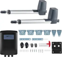
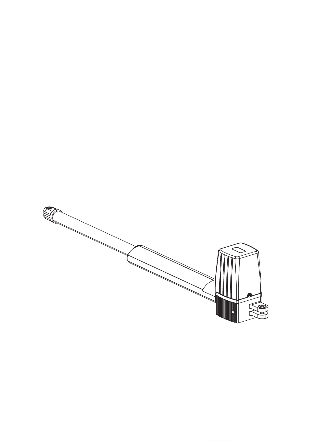
Swing Gate Opener
User Manual
V20231205
Read Carefully Before Use
Keep for Future Reference

1
General Safety
• Read these instructions completely before installation and use. Provide them to any technician
used to install, maintain, or repair this device and provide them with the device if it is ever given
or sold to a third party.
• Install and use this gate operator only in accordance with these instructions and all applicable
local and national laws and regulations. Adding clearly visible warning signs may be necessary
in your area and is a requirement for UL 325 compliance. Only use the device for its intended
purpose, opening and closing gates for Class I residential vehicular trac. Always aim to
minimize public exposure to potential hazards such as pinch points. Failure to do so may result
in serious property damage and severe personal injury.
• ONLY use this device for a gate intended for vehicular trac. If pedestrian trac is expected, it
should be provided with a separate access point far enough away to ensure everyone on foot
never comes into contact with the moving vehicular gate.
• ONLY use this device with gates of compatible weight and size.
• When properly congured and activated, the gate operator’s collision reaction system functions
as a Type A entrapment protection and an attentive user and the device remote function
together as a Type B1 non-contact sensor. If any other access system is added, additional
contact or non-contact sensors such as photo eyes, edge sensors, and/or infrared sensors may
be necessary to ensure legal and UL 325 safety compliance.
• Install and use this operator only on rm and well-supported surfaces. Install and use this
device so that its motor and other hazardous components are not in public areas and protected
as much as possible from unauthorized access and use. There should be adequate clearance
between your gate and any nearby structures to prevent any possibility of a pinching or crushing
hazard during use. If this is impossible, the area should be guarded as well as possible and
warnings placed nearby.
• Conrm BEFORE any digging that there are no nearby gas, power, or other utility lines or that
all such lines have been fully disabled and cleared to allow for safe work.
• DO NOT install this device in any area prone to ooding or in locations exposed to ammable
or explosive fumes.
• ONLY install xed controls for the gate where they cannot be reached over, under, around,
or through the gate. They should also be far enough away that operators cannot contact the
moving gate during use. For full UL 325 compliance, there should be a clear line of sight
between the control box and the gate, but the box and any other permanent access system
should still be at least 6 feet (2 m) away from any of the gate’s moving parts.
Electric Safety
• Use a dedicated circuit breaker for the gate opener. The circuit breaker should be located out
of the reach from outside your property and 5 feet (1.5 m) above the ground. Shelter the circuit
breaker from the weather elements.
• ONLY allow trained technicians to install and repair this automatic gate operator and its
electrical connections. Keep electronic components disconnected from any power source
during installation and maintenance except as instructed for safely testing functionality.
• The control box and the actuator have no preinstalled power cords. ONLY use cords with 3
cores and a minimum cross-section of 1.5 mm² (approx. AWG 15).
1. Safety Information
2
• Provide robust protection for the control box power cable. Use PVC conduit or other similarly
sturdy material.
• NEVER allow children to play on or around this device or its attached gate. Keep controls away
from children and out of their reach at all times and warn them of the gate’s danger.
• NEVER pair a remote control for this device with any other control board. Never attempt to
operate this device with two or more remotes or control devices at the same time.
• All provided components of this device are weatherproofed to withstand normal rain. Ensure
adequate insulation and protection of all electrical connections and never direct pressurized
water against any part of this device.
Maintenance Safety
• Never check or clean the piston of the actuator when it is connected to power. Keep your gate
well maintained and the device’s piston(s) free of grime and debris. Periodically conrm that it
runs smoothly under manual operation.
• DO NOT use if any component is missing, loose, worn, or damaged. Tighten, repair, or replace
problematic parts before further use. Only replace components with identical parts and always
fully replace damaged electrical cords.
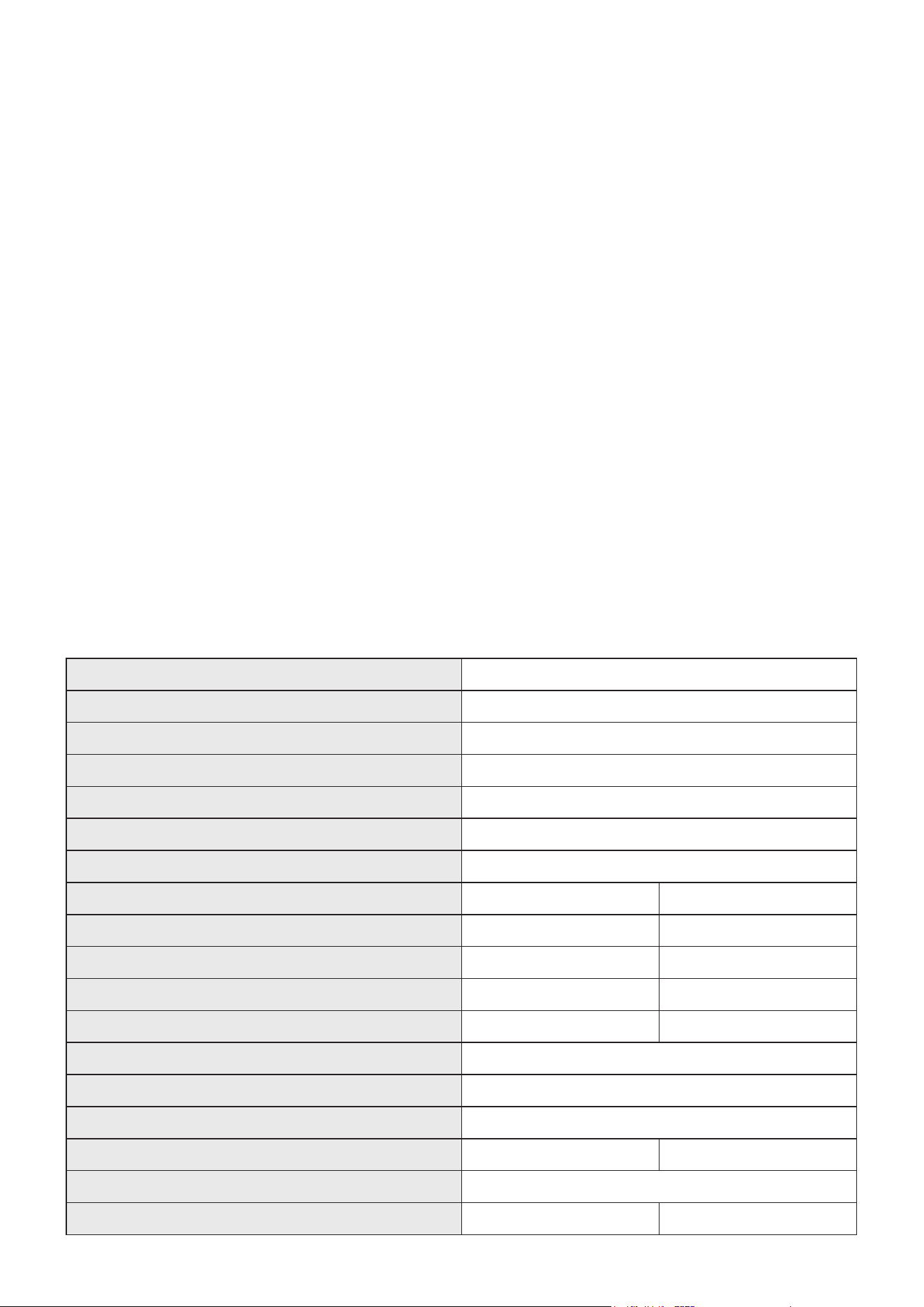
Model PK300DC
Voltage
110 V/60 Hz
Power
80 W
Est. Time to Open/Close 90°
18–22 sec.
Gate Open Delay
0–10 sec.
Gate Close Delay
0/15/30/60/90 sec.
Duty Cycle
S2 30 min.
Max. Single-Leaf Gate Weight
650 lb. 300 kg
Max. Single-Leaf Gate Length
9′10″ 3 m
Actuator Max. Stroke
21.1″ 54 cm
Max. Force(ea.)
337.5 lbf 1500 N
Max. Remote Control Range
98.4 ft. 30 m
Max. Noise
58 dB
Max. Remote Pairs
32
Frequency
433.92 MHz
Working Temperature
−4 to 158°F –20 to 70°C
Weatherproong
IP44
Net Weight
37.7 lb. 17.1 kg
2. Specications
3
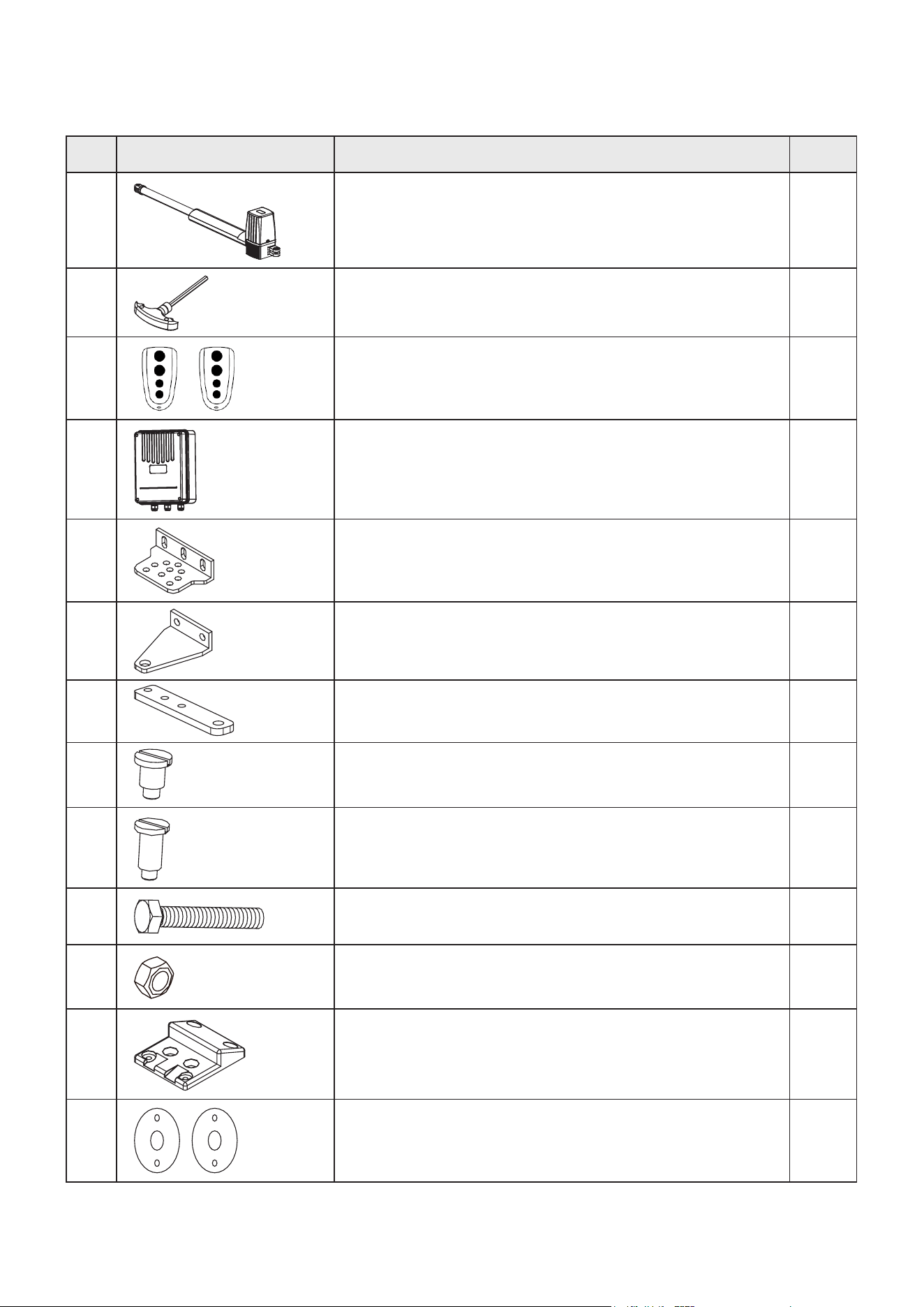
2.1 Package List (Standard)
No. Illustrations Items Qty.
A
Actuators 2
B
Manual Release Key 1
C
Remote Controls 2
D
Control Box with Casing 1
E
Post Brackets 4
F
Gate Brackets 2
G
Post Pivot Brackets 2
H
Actuator Tip Bolts (short) 2
I
Actuator End Bolts (long) 2
J
Screw M8×25 4
K
Nut M8 8
L
Limit Stop 1
M
Wired Photocells 1
4
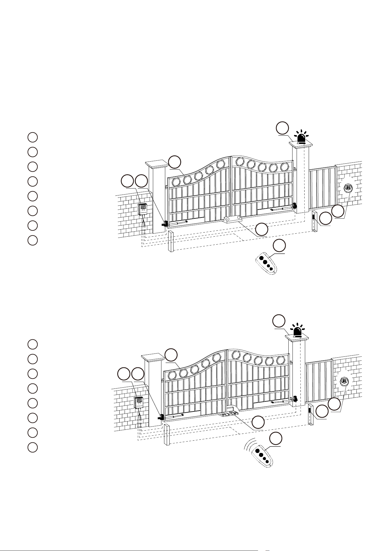
Overview
Push-to-Open
Refer to the diagram above for where things should be. Note that there are too ways to install
the actuators: push-to-open and pull-to-open. Each way only works properly with the limit stop
properly installed (L).
1
Control Box
2
Actuator
3
Gate
4
Alarm Lamp
5
IR Sensor (Optional)
6
Limit Stop
7
Remote Control
8
Keypad (Optional)
Pull-to-Open
1
Control Box
2
Actuator
3
Gate
4
Alarm Lamp
5
IR Sensor (Optional)
6
Limit Stop
7
Remote Control
8
Keypad (Optional)
3. Installation
0
8
56
97
4
123
3
4
5
6
7
8
1 2
Property Outside
Property Inside
0
8
56
97
4
123
3
4
5
6
7
8
1 2
Property Outside
Property Inside
5
Installation Preparation
Required Tools
• Power Drill/Hammer Drill
• M8 Drill Bits
• M8 Bolts & Nuts× 4
(1)
• M8 Expansion Bolts & Nuts× 8
(2)
• Tape Measure
• Adjustable Wrenches
• Wire Strippers
• Spirit Level
• Hacksaw or Heavy-Duty Bolt Cutters
• Phillips Screwdriver
• Pickaxe
• PVC Conduits
• Marker
(1) Length of the bolts depends on the exact thickness of the gate beam to which you will attach
the gates brackets.
(2) Length of the expansion bolts depends on the exact thickness of the posts to which you will
attach the post brackets.
Pre-installation Check
Actuator End Bolt (long)
M8 Nut
Actuator Tip
Bolt (short)
M8 Nut
6
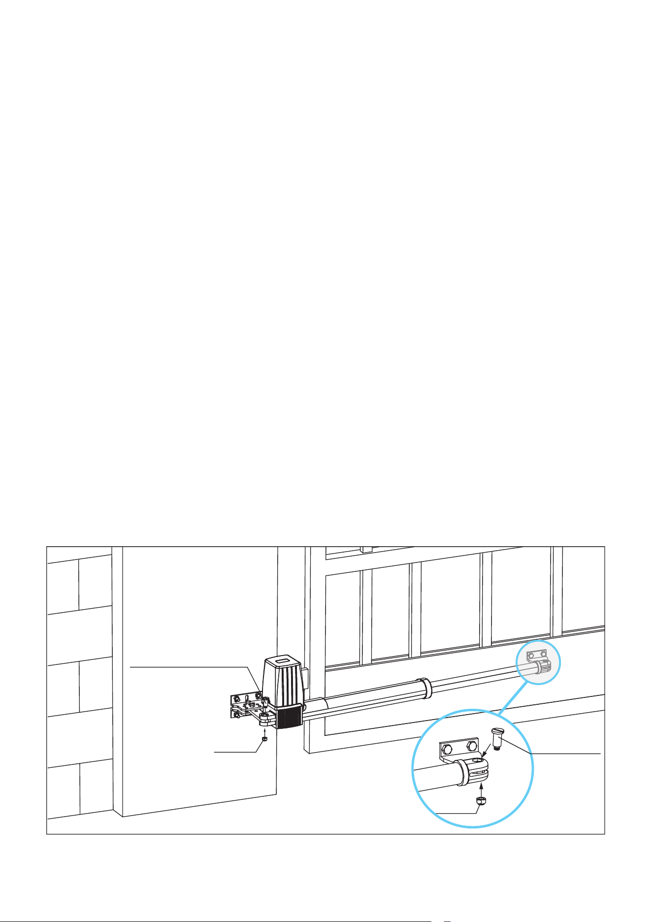
Referring to the diagram above, check that:
• Both your gate leaves have a horizontal beam sturdy enough to bear the push and pull of the
actuator. Ideally the beam should be metal or solid wood at least.
• The post on which the gate is mounted has a sturdy structure and provides drillable surface
facing the inside of your property.
• Both beams are about 11.8–31.5 inches (300–800mm) above the ground.
• Your gate is plumb and level both vertically and horizontally. Conrm that it swings smoothly
on its hinges throughout its full range of motion without any binding or contact with the ground.
Conrm that its posts are rmly secured in concrete and that the gate itself will not bend or ex
once its movement is automated. Lubricate, repair, and reinforce the gate’s components as
needed.
• All of the hinges’ fasteners are securely xed to the post or wall. Reinforce as needed.
• The ground on which the limit stops will be installed is rm enough to withstand the moving
weight of the gate.
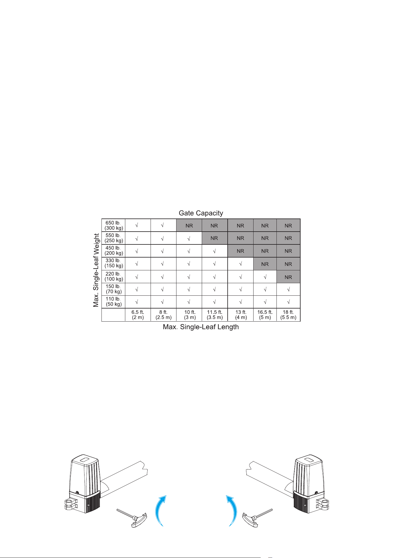
• Your automatic gate operator will be able to provide the necessary torque using the chart
below.
• If you will use an electronic lock with your gate, make any necessary adjustments so that the
two sides connected by the lock are spaced ⅝ to ¾ inch (1.5–2 cm) apart. (If you will not use
an automated electronic lock, any range should be ne.)
Actuator Positioning
1. Unlock the actuator.
a) Fetch the manual release key (9) to each actuator.
b) insert it to the key hole on its corresponding actuator.
c) turn the key the way as shown below.
7
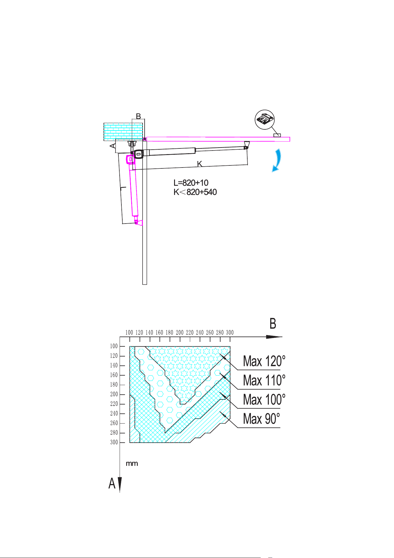
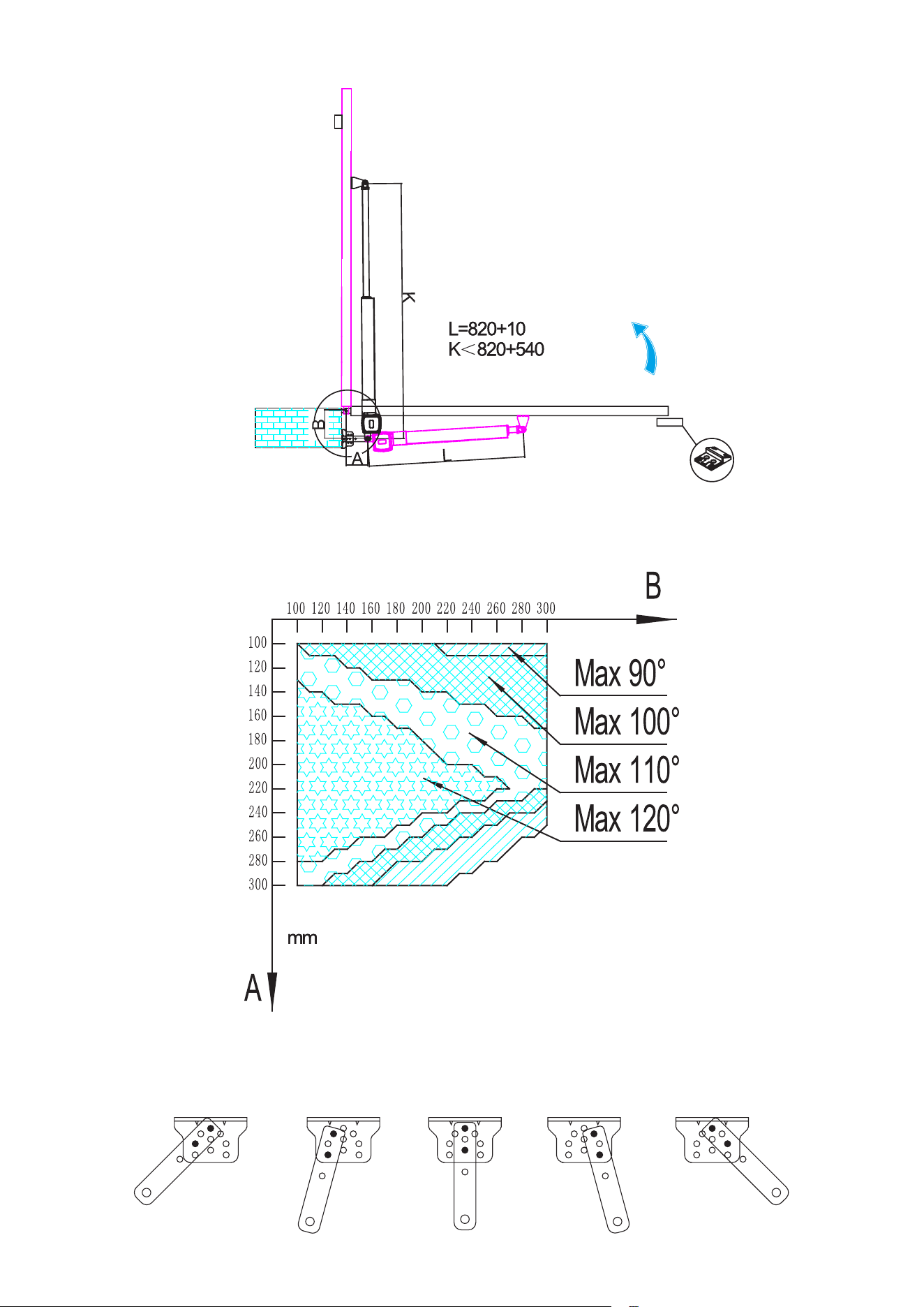
2. Determine the mounting positions and for the post brackets and gates bracket referring to
the diagrams below, which show the maximum opening angle for a given horizontal (B) and
vertical (A) distance between bracket joints and gates in millimeters.
Note: Limit stop must be installed
8
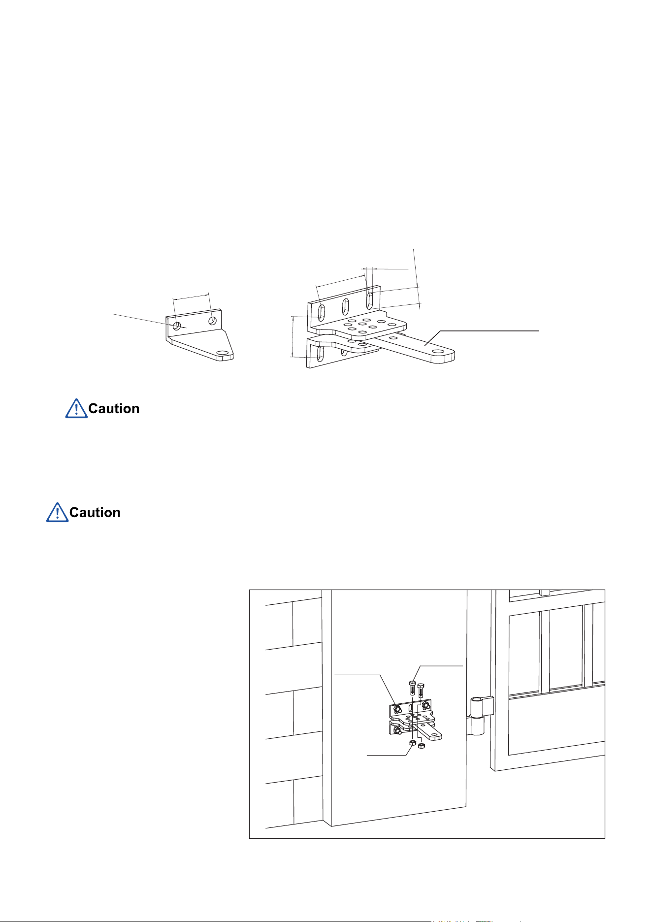
Note that the post pivot bracket can be installed in the following fashion. Choose one that
works with your specic gates and post.
Note: Limit stop must be installed
This limit stop is not included.
Purchase one that can handle
the weight of your gate.
9
3. Mark the positions of the post brackets and gate brackets on the post and gate beam using
your marker (not included).
4. Repeat Step 2–3 for the other actuator.
Use the four diagonal holes on the two post brackets.
Positioning the Brackets
1. Press the gate brackets on the beam and the post brackets referring to the marks you have
made above.
2. Again, using your marker, mark the positions of the bracket’s hole on the gate and post. Refer
to the bracket specications for quick marking.
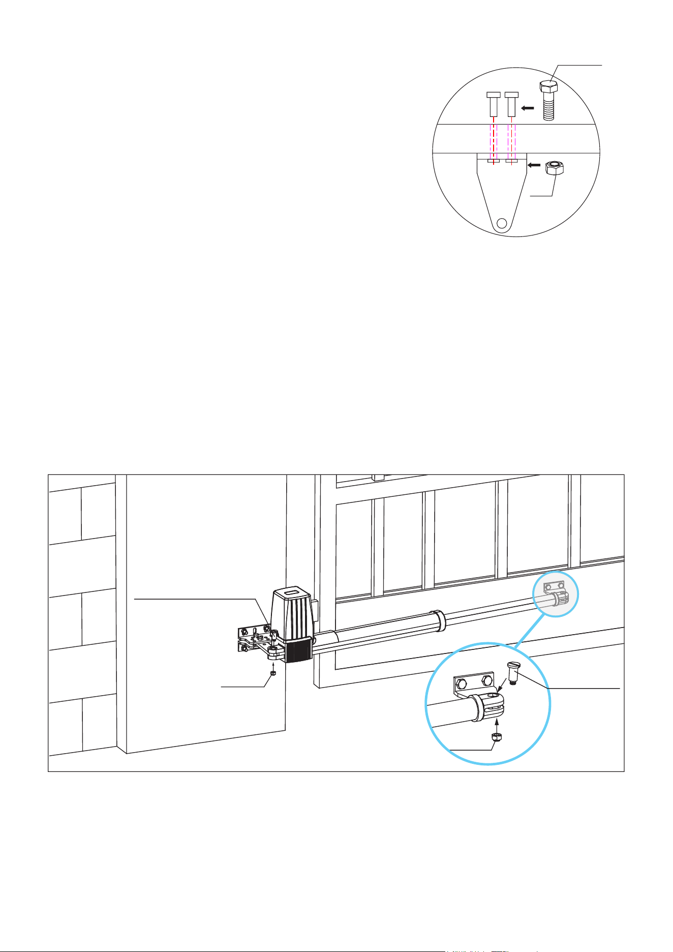
Installing the Brackets
Do not use hammer drills on wooden posts, which could crack easily upon the impact of such drill.
Instead, use drills and M8 bolts long enough to impale the post
1. Drill a hole at each mark
that you made for the post
brackets using a power
drill or hammer drill (not
included), depending on the
exact material of the post.
2. Bolt the post brackets to the
post the way as shown using
your adjustable wrench and
the M8 expansion bolts or
regular bolts long enough
to pass through the whole
thickness of the post.
3. Insert the post pivot bracket
into the two post brackets
and fastening it in place with
2 of the provided M8 bolts
and nuts (J & K).
M8 Expansion
Bolts
M8 Bolts
M8 Nut
Gate Bracket Post Bracket
Post Pivot Bracket
2×Φ8.5 mm
40 mm
43 mm
70 mm
8.5 mm
17.5 mm
10
4. Drill a hole through each mark that you made for the gate
bracket using a power drill.
5. Bolt the gate bracket to the gate using your regular M8 bolts
and adjustable wrench.
6. Repeat Step 1–5 for the other gate bracket and post
brackets.
M8 Bolts
M8 Nut
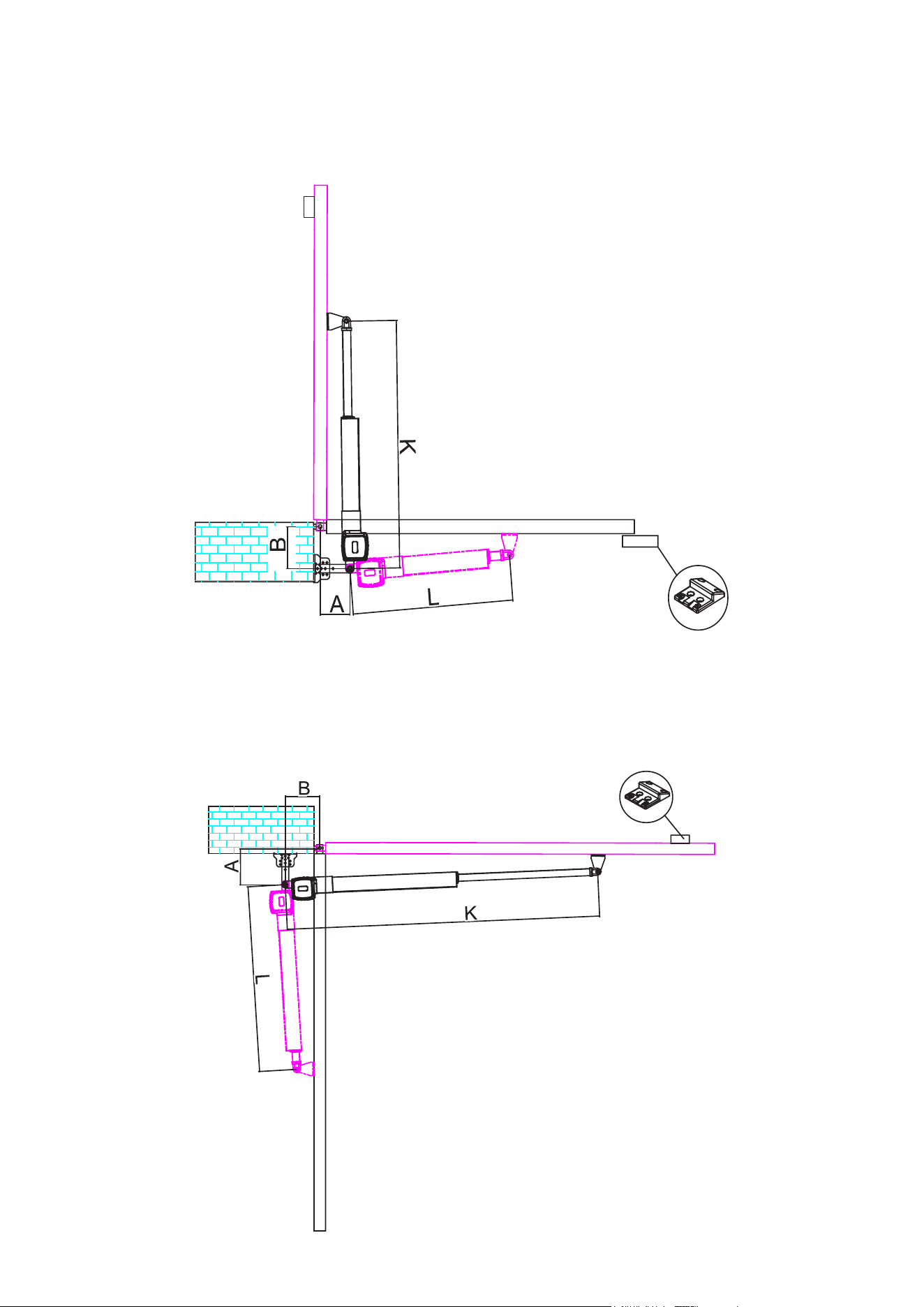
Mounting the Actuators
1. Mount one actuator to the gate bracket and post brackets the way as shown.
2. Repeat Step 1 for the other actuator.
Actuator End Bolt (long)
M8 Nut
Actuator Tip
Bolt (short)
M8 Nut
11
Installing the Limit Stops
For Push-to-Open installation, refer to the diagram below for where the limit stop should be installed.
For Pull-to-Open installation, refer to the diagram below for where the limit stop should be installed.
Limit Stop
Limit Stop
This limit stop is not included.
Purchase one that can handle
the weight of your gate.
12
Mounting the Control Box
Pre-Mounting Check
Check that:
• The gate will not enter or obstruct ANY public area once its movement is automated.
Ifthisisimpossibleforyourlocation,getspecicapprovalfromtherelevantauthority.Postclear
warningsandtakeeveryprotectivemeasurenecessarysothegatewillnotriskaccidentsor
block any public right of way.
• The location for your control box is within sight of the gate but at least 6 feet (2 m) from any
moving part. Never mount it on the same post as the gate itself. For best results, mount the
box on a sturdy level surface within 6 m (20 feet) of the gate opener in a position inaccessible
to anyone reaching through the gate. It must be at least 3 feet (1 m) above the ground to avoid
damage from rain and snow and, for best results, place it 5 feet (1.5 m) or higher to help keep
it inaccessible to small children and animals.
• The location of the control box is at least 3 feet (1 m) away from any power outlet to avoid
possible electrical interference. When using AC power, its own outlet should be visible from
the gate and equipped with a GFCI or circuit breaker. If no outlet is available within 300 m
(1000 feet) of the control box, the gate should be powered by a 24V DC battery, two 12V DC
batteries wired to provide 24V power, and/or a dedicated solar system adequate to its needs
(sold separately) or a licensed electrician should be consulted to safely make the necessary
adjustments to handle the expected voltage drop along the power cord.
• If using AC power, check that you have main power cord and control bx wire of the correct
gauge and length. If you will be using additional wire to extend the length of the provided power
cord, be sure to keep all connections clean and well insulated. Any additional wiring should be
a 3-core cable at least 1.5 mm² (16 AWG) thick for distances less than 90 m (300 feet) and 2.5
mm² (14 AWG) for distances beyond that. If the power outlet is located a considerable distance
from the control box, the wiring should be placed inside a weatherproof PVC sheath and buried
to avoid damage from animals, vehicles, etc. and minimize any risk of tripping.
• All lines are fully disconnected from power.
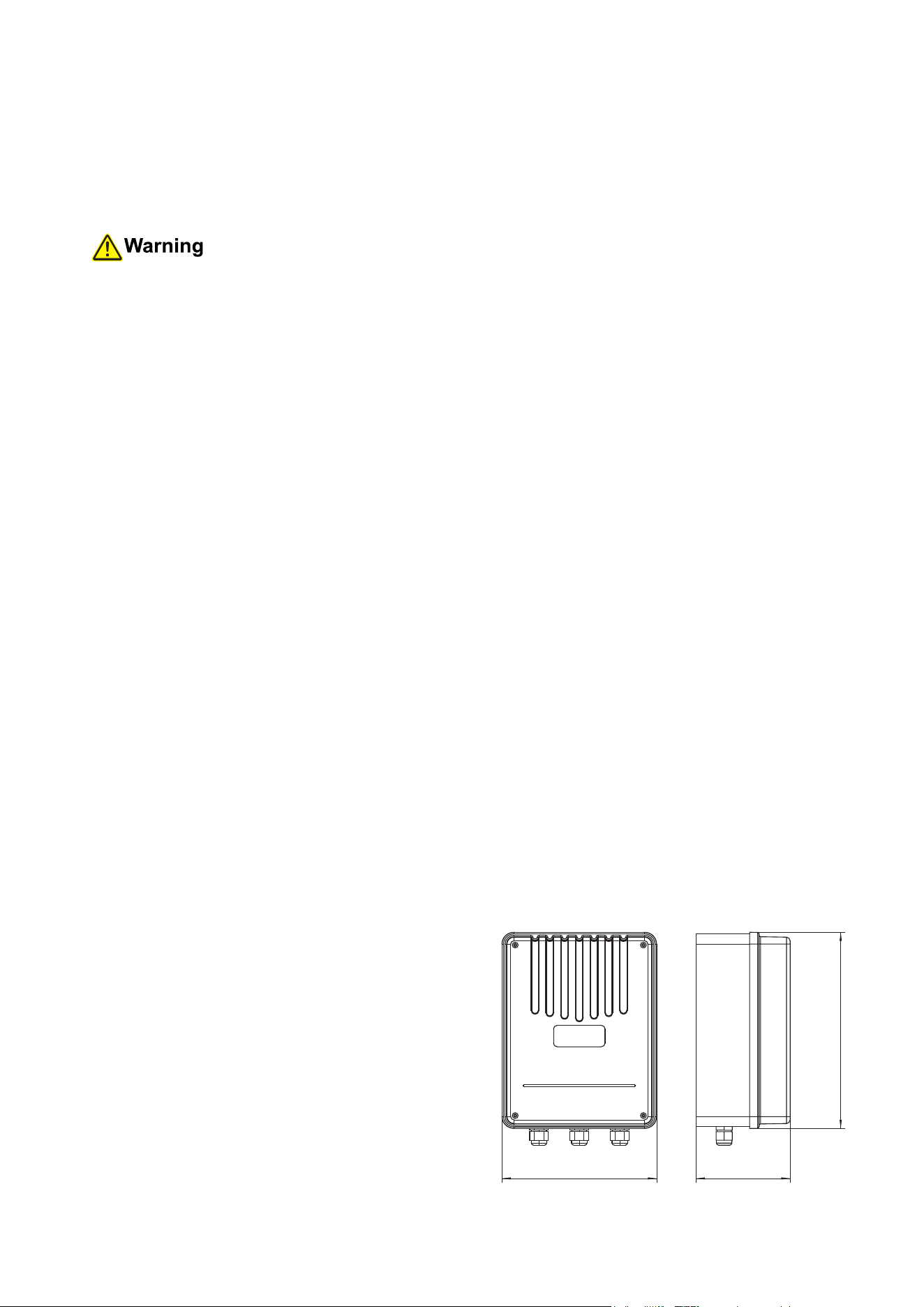
Control Box Installation
1. The control box should be attached to the
location previously selected using 4 deck
screws or 4 anchor bolts (not included). Be
sure the box’s strain relief slots are all pointed
DOWN to help drain excess moisture.
2. Remove the protective cover from the control
box. Keep its fasteners nearby. Loosen the
strain relief slots at the bottom of the box.
In each step below, feed the wires through
the strain reliefs before making connections
so the wiring can be held securely in place
between adjustments.
8.3 in.
(210 mm)
5 in.
(120 mm)
10.9
(275 mm)
13
Wiring
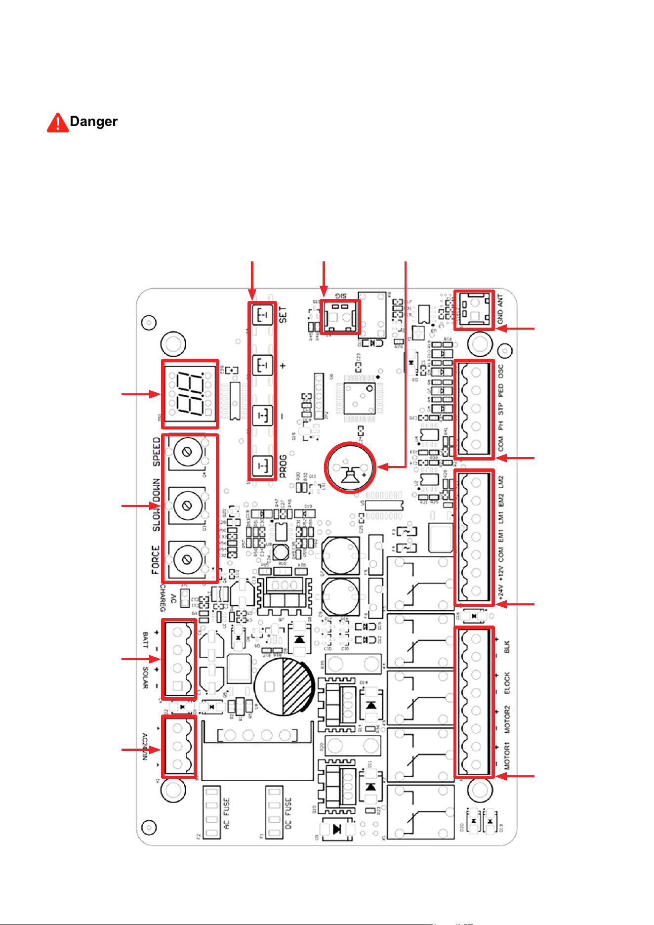
Circuit Board Diagram
NEVERmakeelectricalconnectionswhileyourpowersupplyisactive.TurnoyourACpoweror
disconnect your battery terminal(s) during any wiring adjustment.
Adjustment
Buttons
Digital
Display
Adjustment
Knobs
X2 Terminal
X6 Terminal
X5 Terminal
X4 Terminal
X3 Terminal
X1 Terminal
Signal
Terminal
Alarm
14
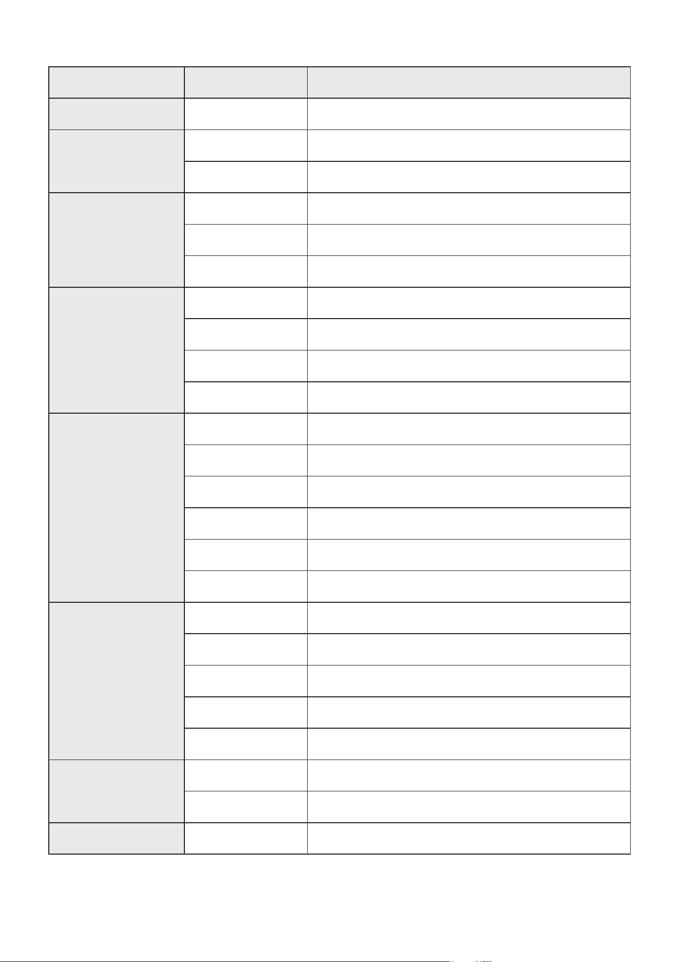
Terminals Pins Descriptions
X1 Terminal
AC24VIN 24V AC input
X2 Terminal
+SOLAR- Solar battery input and output
+BATT- 24V DC input and output
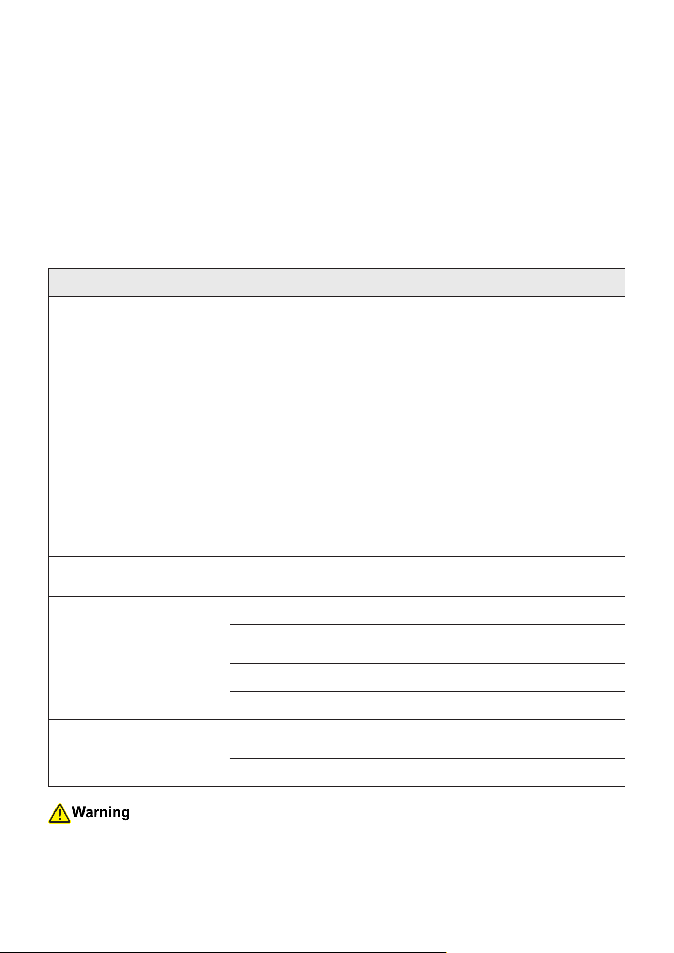
Adjustment Knobs
FORCE Obstruction sensitivity adjustment
SLOW DOWN Stop distance adjustment
SPEED Speed adjustment
X3 Terminal
MOTOR1 Motor 1 input and output
MOTOR2 Motor 2 input and output
-ELOCK+ Electronic lock input and output
-BLK+ Alarm lamp input and output
X4 Terminals
+24V 24V DC output
+12V 12V DC output
EM1 Disabled
LM1 Disabled
EM2 Disabled
LM2 Disabled
X5 Terminal
COM DC Ground
PH Photocells input
STP Keypad stop button signal input
PED Keypad open button signal input
OSC Cyclical control signal input
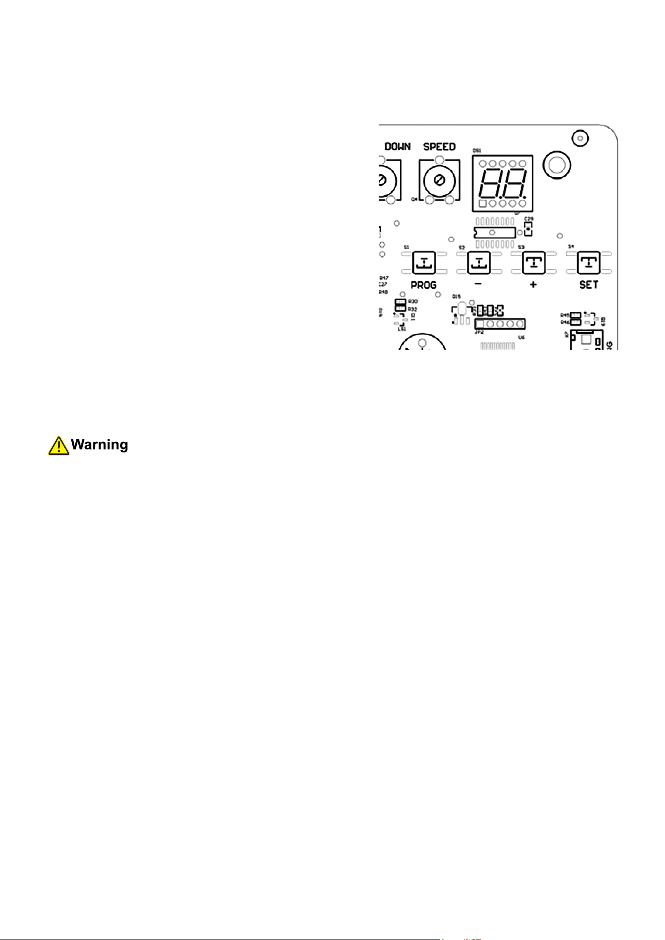
X6 Terminal
ANT Remote control antenna
GND Antenna ground
Signal Terminal
SIG Wi-Fi module signal input and output
15
Power Options
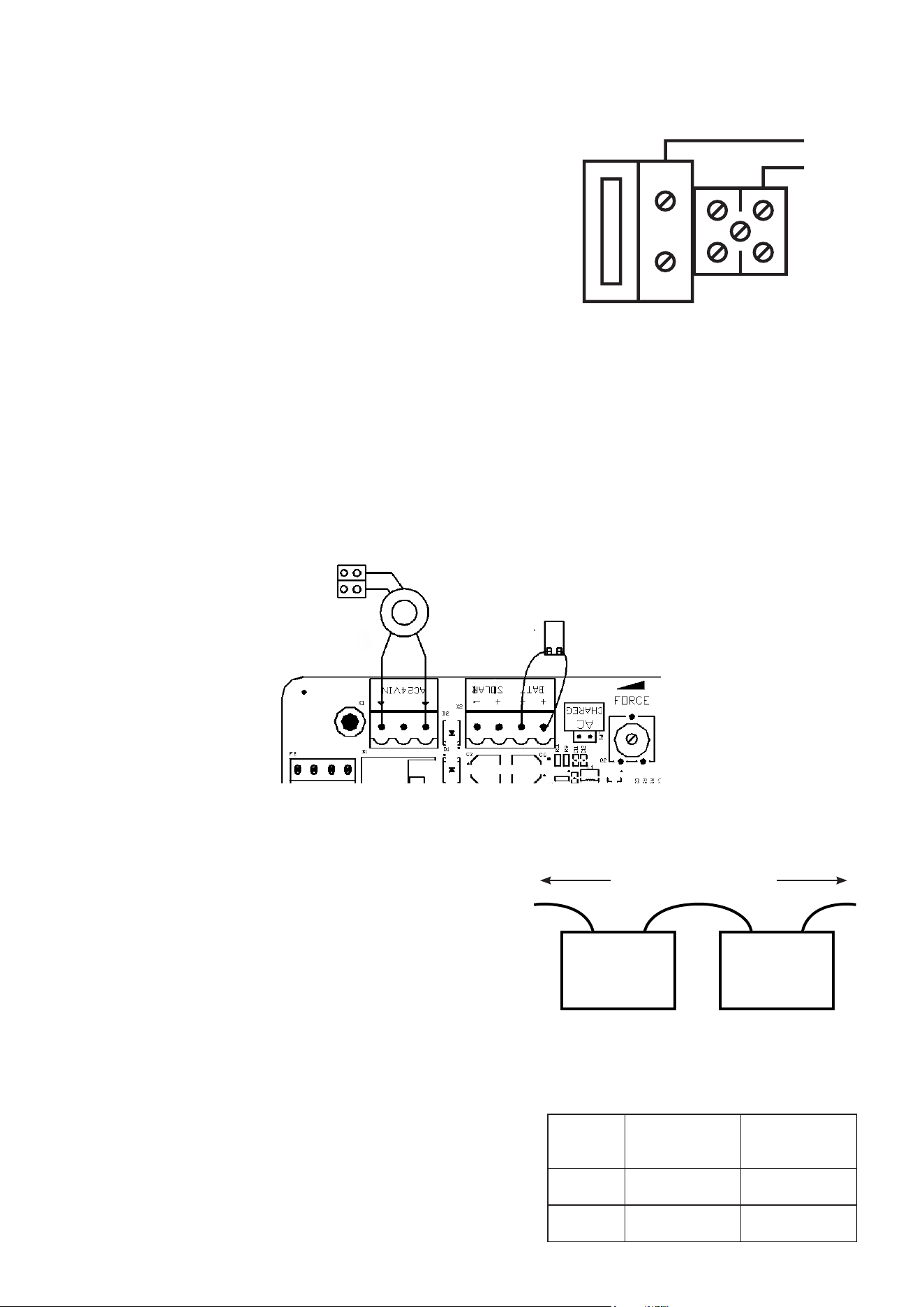
• If you will be using AC power, connect the provided
cord or your extension to the main power terminal.
This small white box runs to a 10A fuse and 24V
transformer which should be prewired to the part of
the circuit board's X1 terminal marked AC24VIN. Use
a small screwdriver to loosen and tighten the main
power terminal’s screws as needed. Connect the
ground wire to the central pin, the live wire to the left
pin, and the return or neutral wire to the right pin. Be
sure no wiring is left bare and exposed.
L PE N
If you will be using a dedicated solar system, follow its separate instructions for installation,
adjust its wiring so no power will be owing as you work, and connect its live wire to the
SOLAR+ pin on the X2 terminal and its return or neutral wire to the SOLAR− pin. Any gate
that will be using a solar system should also have a 24V battery attached (see below). This
will allow the solar system to charge it during sunny days but still provide consistent service at
night, in poor weather, and on occasions where the operator(s) must be used repeatedly in a
short time.
To use a 24V battery to provide primary or backup
power, prepare weatherproof housing for it near the
control box. Two 12V batteries can also be used as
a single 24V unit by wiring the negative terminal
of the rst battery to the positive terminal of the
second. Whether you are using one or two batteries,
leave one terminal disconnected to prevent power
from owing during setup and adjustment. Connect
the live wire from the battery's positive terminal to
the BATT+ pin on the board’s X2 terminal and the
return or neutral wire from the negative terminal to
the BATT− pin.
10A Fuse
24V Battery
+ + − −
to
BATT+
to
BATT−
Wire
Color
Master
Operator
Secondary
Operator
Red MOTOR1− MOTOR2+
Black MOTOR1+ MOTOR2−
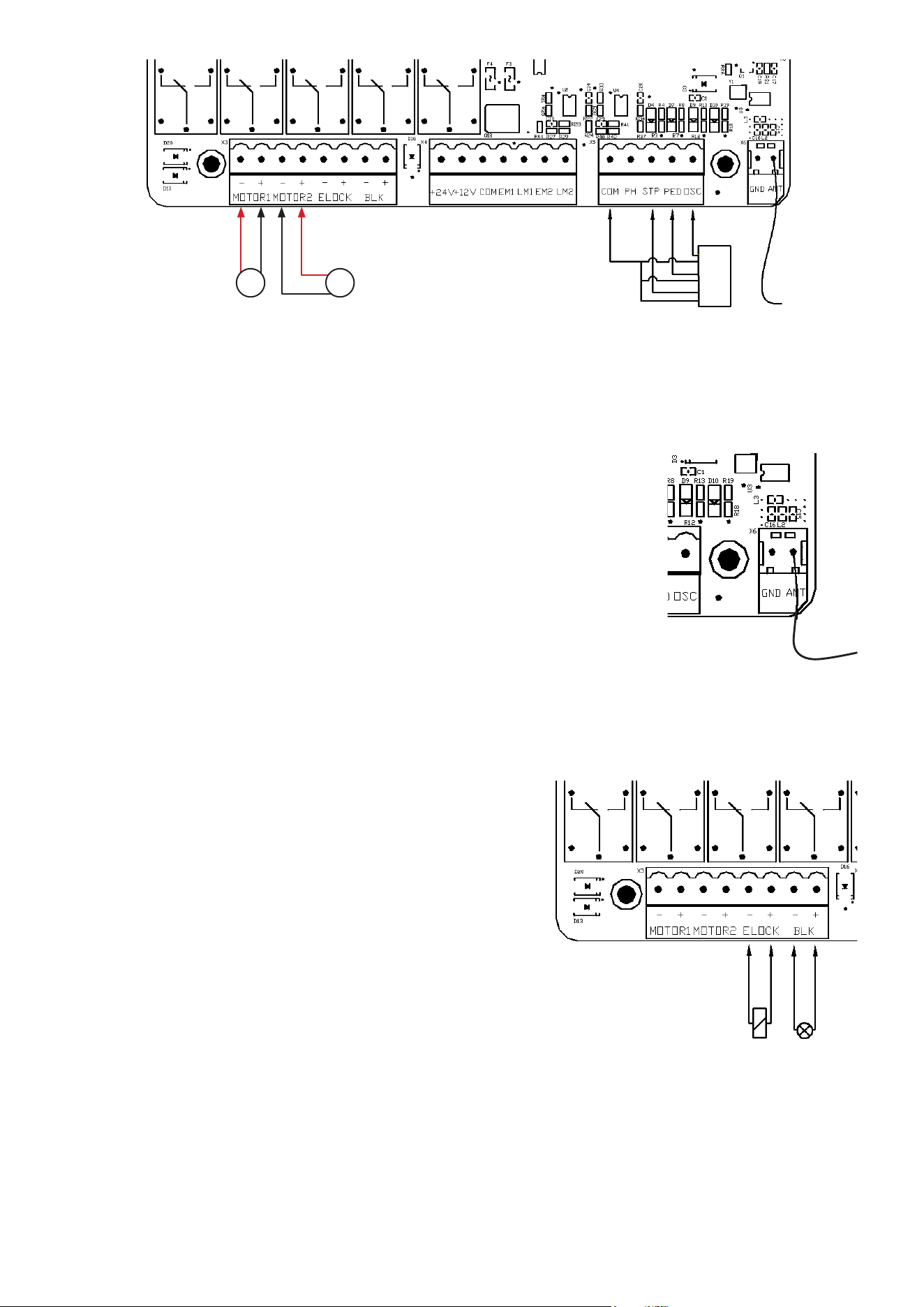
Wiring the Motors
• Each operator should have two wires to connect it
to the circuit board for power and control signals.
Connect them as shown on the right. The MOTOR
pins are located on the board’s X3 terminal.
16
• Double check that the wire from the remote control antenna is securely connected to the ANT
pin on the X6 terminal.
Wiring a Keypad
• If your gate will have a separate keypad entry system, follow its
separate instructions for installation and connect its wiring to the
X5 terminal. The return or neutral wires should be connected to
the COM pin, the signal wire for STOP commands to the STP pin,
the signal wires for pedestrian commands to the PED pin, and the
signal wire for cyclical control—OPEN/STOP/CLOSE/STOP—to
the OSC pin.
Wiring Other Accessories (Optional)
• Connect any other accessories you might wish to use with this gate opener, following their
separate manuals to ensure safe and reliable operation. Some of the more common accessories
for this gate opening system include:
Electronic Locks
To automatically control an electronic lock on your
gate, connect its signal wire to the ELOCK+ pin on
the board’s X3 terminal. Connect its return or neutral
wire to the ELOCK− pin.
Alarm Lights
To automatically activate an alarm or indicator light
when the gate is in motion, connect the light’s signal
wire to the BLK+ pin on the X3 terminal. Connect the
light’s return or neutral wire to the BLK− pin.
Infrared Sensors (“Photo Eyes”)
As shown below, connect the sensors’ common (COM) and return or neutral pins (V−) to the
COM pin on the board’s X5 terminal. Connect the receiver’s normally closed (NC) pin to the
PH pin on the same terminal. Connect the power input pins (V+) on each sensor to the 24V
power supply pin (+24V) on the board’s X4 terminal. Remove any other wire connecting any
of these pins directly, but save any such wire in a safe place in case you ever need to use the
operator(s) without the photocells.
Lock Light
Black
Red
Main Operator
Optional Keypad
Secondary
Operator
KP
M1 M2
17
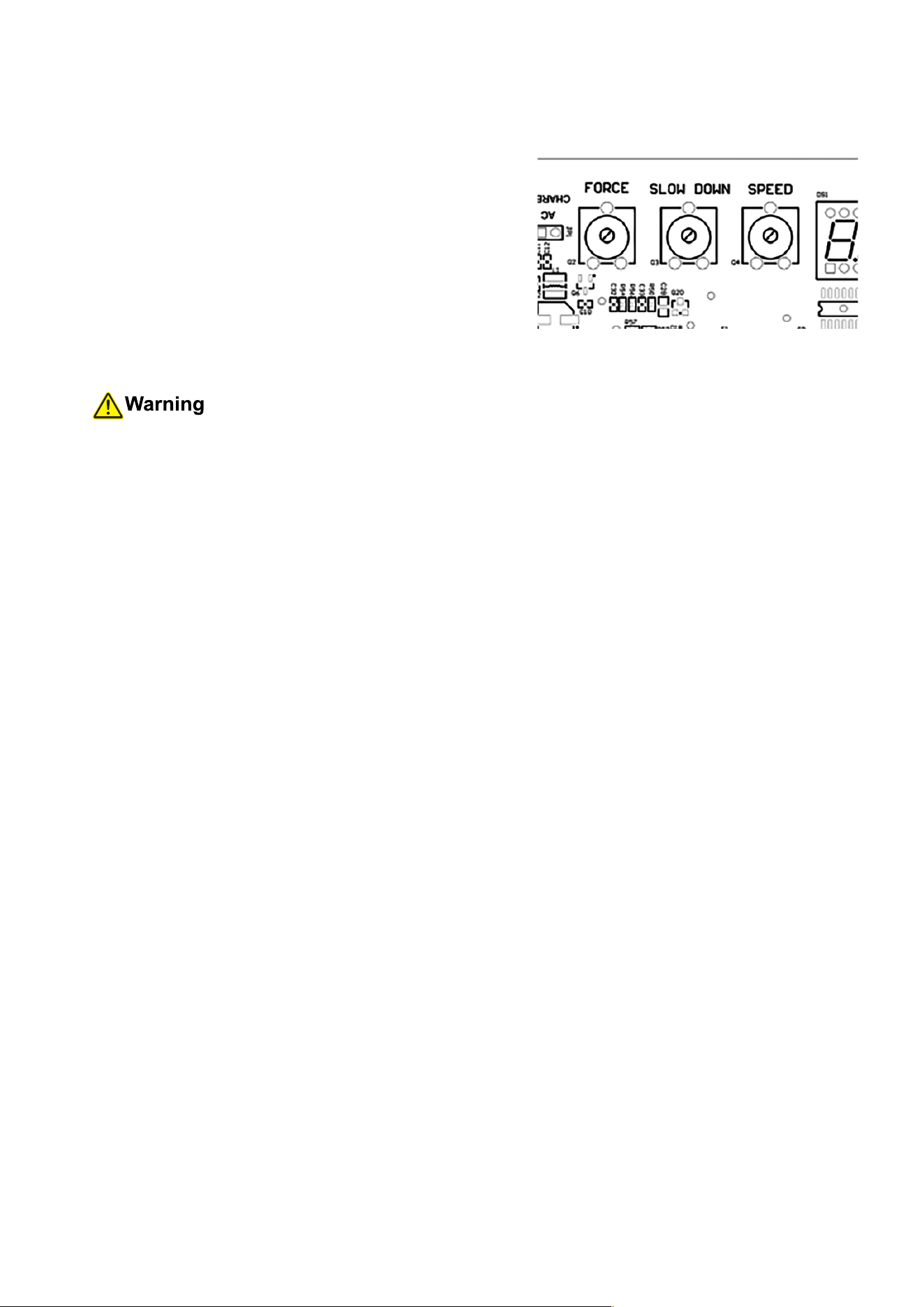
• Your system should come correctly preprogrammed
to work as a single operator for a single gate or as
paired operators for two separate gate leaves.
1. To conrm this before testing the gate, press
the PROG button until the digital display
changes from “--” to “NE”.
2. Press + or – until the display reads “SP”.
3. Press SET to conrm that the circuit board is
using the proper operational mode. The display
should read “OF” for one operator working
alone and “ON” for two operators working
together.
4. If the setting doesn’t match your system, use +
or – to toggle to the correct setting and press
SET to conrm your change.
Setting PSO
InstallthelimitstopoutsideyourgateifyouchoosetousePSO.
• Your system should come preprogrammed to use pull-to-open operation, opening inward
towards your property. If your gate will be using push-to-open operation instead, pushing the
gate outward, you will need to reset that parameter.
1. Press the PROG button until the digital display changes from “--” to “RL”. Press + or – until
the display reads “dR”.
2. Press SET to enter the submenu and use + or – to toggle the setting from “IN” to “OU”.
3. Press SET to conrm your change.
Initial Testing
Setting Dual Actuators

18
Travel Setting
• By default, the actuator works under such a mode: it runs at full speed for 15 seconds after
receivingasignaltoopenthedoorandonlyslowsdownwhencomingintocontactwithalimit
stoporawall.Thisdefaultmodeiscustomizable,butitisrestoredEVERY TIME the SPEED
adjustment knob is turned.
• ALWAYS retrain the circuit board about the limit stop once the SPEED adjustment knob is
turned.
•Clearanyobstaclesfromthegate’spathandkeepallbystandersawaythroughoutthefollowing
steps.
Upon using the actuator(s) to open or close your gate for the rst time, DO set its travel distance
following the steps below so that your gate can stop at the right position and at your desired speed.
1. Open your gate to its half-open position and lock the operator
2. Hold the + button on the control board until the display reads “SU”.
3. Your gate should start to close, stop at the limit stop, open to its fully opening position, and
close and stop for a second time, indicating the retraining is done. If your gate did not start
to close but to open, access the circuit board and switch the negative wiring with the positive
wiring of the motor.
AT T E NT I O N ! ForeitherPLOorPSOsetup,afterbeinginitiallyopened,yourgateshouldbe
movingtoitsclosedposition.Ifitismovingintheotherdirection,stopitandswitchtheoperator’s
motorpins’wiringonthecircuitboard.
19
• If the gate starts up too slow or too fast, use the
SLOW DOWN knob on the circuit board to adjust
the speed.
If the door stops abruptly due to wind or the friction
of the gate itself or if the gate does not react
appropriately to the end stops or closes you are
using, turn FORCE knob to adjust the operator’s
force against resistance.
If you, by accident, turned the SPEED knob during
any point of these steps, you have to start all over
again.
Setting the Speed & Obstruction Sensitivity
ALWAYS retrain the circuit board about the limit stop once the SPEED adjustment knob is
turned.
Testing the Single Control Mode
• The top button on both remote controls should already be paired with your circuit board. They
use a single control mode at a distance of up to 98 feet (30 m). Pressing either button should
cycle through the commands OPEN→STOP→CLOSE→STOP. Test both remotes through the
full cycle of commands. The gate should now automatically stop at the right places but be ready
to manually stop the gate using the remote if the memorized settings do not activate correctly.
Conrm that the display shows “OP” as the door is opening and “CL” as it is closing. (If the top
button on either remote does not control the gate, see below for pairing instructions and then
repeat this testing.)
Testing the Closing
• Your system does not come preprogrammed to automatically close your gate after reaching its
fully open position. If you activate this function (see below), test that it works correctly by using
either remote to open the gate to its fully open position and waiting to see if it begins closing
automatically. Conrm that the remote can still stop the gate when it is closing automatically.
• If you have installed any additional safety features like an infrared sensor system or magnetic
detection loops, test them now and conrm that they work correctly and safely.
• Disconnect your system from its power source. If any abnormalities have been detected during
testing, make the necessary adjustments—e.g. by repositioning your end stops, shifting the
adjustment knobs, or changing the stored parameters (see below)—or contact Customer
Service. Once everything is functioning, replace the circuit board and motor covers and their
fasteners, reconnect power, and enjoy!

20
The top button of each included remote should come already paired with your gate opener. Up to
30 additional remotes or wireless control buttons can be paired to the gate’s circuit board. Be sure
that they use the 433.92 MHz (LPD433 Channel 35) radio band or can be congured to do so.
NEVER pair the same button to 2 dierent gates or devices at the same time.
1. Remote pairing must be done with the circuit board exposed and connected to power. Be careful
and only touch the adjustment buttons while the circuit is live. Disconnect your power supply
while the control box’s cover is being removed or replaced and while making any adjustment to
any wiring.
2. Press the − button until the digital display shows the current remote control mode (“PO”, “Pd”,
or “SE”) and then displays the number of currently paired remotes. Release the − button.
3. Press the remote button to be paired or enter a passcode and press the open button on your
wireless control.
4. Press the same button on the remote control again or reenter the passcode and press the open
button again on the wireless control. The digital display should show the new total number of
devices and then automatically return to standby mode, displaying “--”.
5. The button or keypad is now paired and can be used to open or close the gate. This pairing
should remain stored in memory even when power to the gate opener is cut accidentally or at
its circuit breaker.
6. Test that your gate responds correctly to commands from the new remote or keypad. When you
are nished pairing and testing, disconnect the gate from power, replace the control box’s cover
and fasteners, and restore power.
When remote inputs are handled in four-button mode (see the “Pd” setting below), you can also
pair a remote without opening the control box. Hold the bottom two buttons on any previously
installed remote control to authorize remote pairing. Hold the bottom two buttons on the new
remote to pair it. Test that each of the four buttons works safely and correctly.
This board cannot unpair an individual remote. If you need to remove lost remotes from the system’s
memory, you will need to delete ALL stored remotes at once. Open the control box as before. Hold
the + button for about eight seconds. (Alternatively, press the PROG button until the digital display
changes from “--” to “NE”. Press + or – until the display reads “RE”. Press SET to access the
remote submenu. Press + or – until the display reads “rE”. Press SET to conrm the deletion and
exit.) Use any remote to test that all stored remotes have been purged.
Once this process is successful, pair the remotes that you want to continue using in the same way
as before.
4. Remote Pairing
21
Aside from the three settings controlled by the adjustment knobs, all other parameters are controlled
using the adjustment buttons and the digital display. There are two separate menus, one for basic
settings and another for advanced settings.
In each case, use PROG to enter the main menus; + and – to toggle through menus and adjust
values up or down; and SET to select submenus or conrm and save your changes. You can also
wait one minute for the system to reset to standby (“--”) without saving changes.
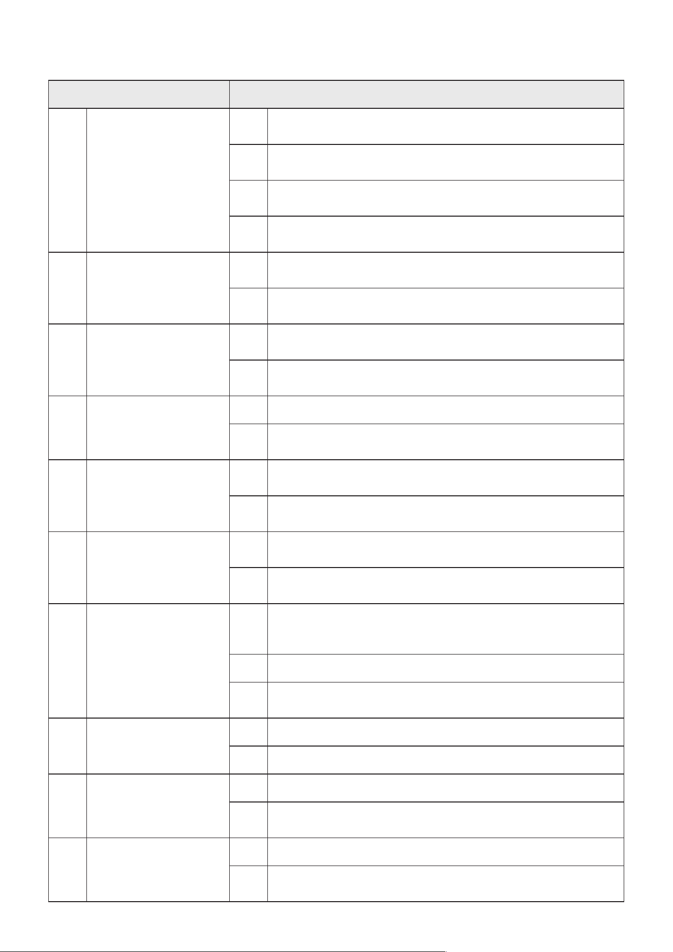
Basic Setting Menu
Electronic locks cannot be used when the OH value is set to 0, 1, or 2 seconds.
Submenu Name Options
NE
Operational Mode
SA
Use this setting for standard operation without autoclosure
PE
Activates automatic gate closure
HO
Activates automatic gate closure and only responds to
one remote at a time (for commercial and large residential
units)
oc
Use this setting for standard xed 3 button control systems
oA
Use this setting for 3 button systems with automatic closure
SP
Gate Mode
ON
Use this setting for 2-leaf gates with twin operators
OF
Use this setting for single gates with a single operator
OH
Gate Open Delay
##
Automatically delays opening the gate after a signal is
received for this number of seconds (3 sec. default)
CH
Gate Close Delay
##
Automatically closes the gate from a fully open position
after this number of seconds (15 sec. default) if activated
RE
Remote Settings
PO
Uses standard cyclical operation from a single button
Pd
Uses four separate buttons for opening, closing, stopping,
and opening the master side only on a 2-leaf gate
SE
Opens only the master side of a 2-leaf gate
rE
Deletes a saved remote (see above)
LC
Energy Saving Mode
ON
Reduces power consumption after more than 1 minute
without use but causes a slightly slower response time
OF
Uses standard operation
5. Parameter Adjustment
22
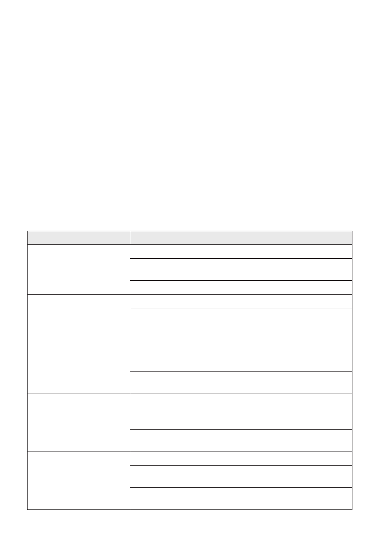
Advanced Setting Menu
Submenu Name Options
rL
Resistance Limit Time
r1
Sets the time in seconds that the master operator will slow
at each end of its movement
r2
Sets the time in seconds that the secondary operator will
slow at each end of its movement
L1
Adds a value in 1/100ths of a second to the r1 value for
ne tuning the master operator’s movement
L2
Adds a value in 1/100ths of a second to the r2 value for
ne tuning the secondary operator’s movement
PH
Infrared Mode
NO
If an infrared sensor is attached to the system, use this
setting for those that use a normally open signal
NC
Use this setting with any infrared sensors that use a
normally closed signal
EL
Electric Lock Mode
NO
If an electronic lock is attached to the system, use this
setting for those that use a normally open signal
NC
Use this setting with any electric locks that use a normally
closed signal
Oc
Lock Pushback
NO
Opens the gate directly
YS
Pushes outward when rst opening, used to prevent
catching on some delayed electric locks
PA
Alarm Light Mode
NO
If an alarm light is attached to the system, it will stay on
continuously when the gate is in motion
FL
Any alarm light will ash on and o when the gate is in
motion
LP
Limit Mode
RS
Processes the open and close limits based on stored
values and resistance detection
LS
Do not use this setting for these operators, as it requires
additional wiring and components
Nd
Gate Type
00
Use this setting for extremely heavy gates that respond
poorly even with the POWER adjustment knob is at its
maximum
01
Use this setting for standard gates
02
Use this setting for better operation with extremely small or
light gates (under 110 lb. or 50 kg)
dr
Gate Direction
IN
Use this setting for pull-to-open gates
OU
Use this setting for push-to-open gates
bE
Alarm Buzzer
YS
Sounds an alarm when the gate moves or an error occurs
NO
Disables the alarm (Note that such an audible alarm may
be required for automatic gates in your area)
FP
Parameter Reset
OF
Exits without changes
ON
Removes all stored information, requiring setup to be
repeated
23
• Always supervise children and pets near the gate, the operators, and their controls to prevent
accidents.
• Always fully disconnect the control box from its power supply before removing its cover or
making any adjustments to its wiring, except as specically directed elsewhere in this manual.
Use trained and licensed electricians for rewiring or electrical repair work.
• Keep your gate and its hinges clean and free of any corrosion, grime, or obstructions.
• Lubricate hinges as needed and, in climates where temperatures reach 34°F (1°C) or lower,
spray silicone on the operator piston(s) every 4–6 weeks to prevent freezing.
• If your gate is not in regular use, test your gate opener’s operation at least once a month. If
any problems are noticed during testing or normal use, disconnect the control box from power,
unlock the operator(s), and test manually that the gate still moves smoothly on its own. Tighten,
repair, or replace problematic parts as needed. Only use identical components and always fully
replace damaged or malfunctioning electrical cables.
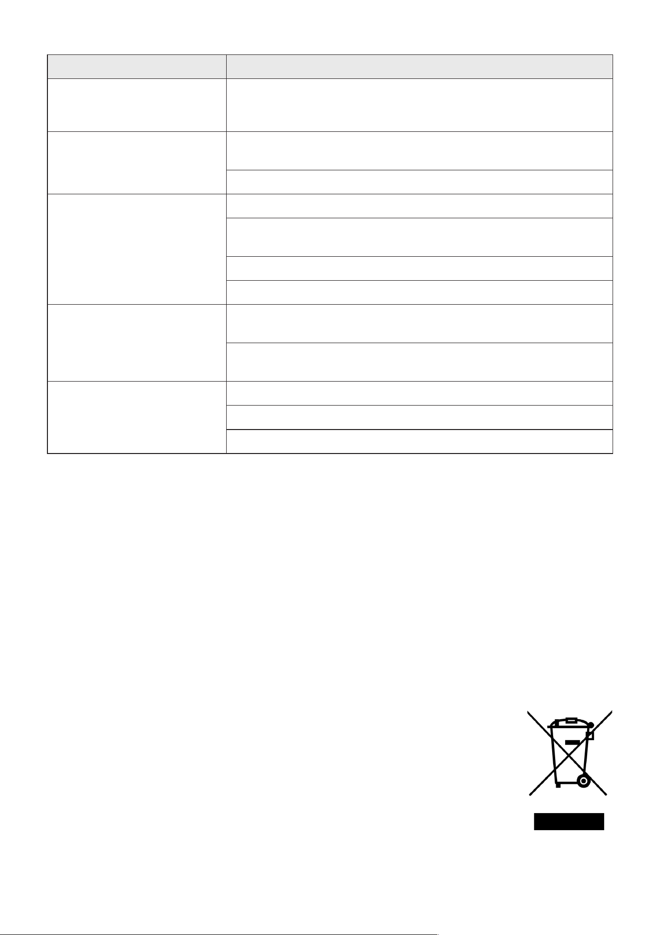
Possible Problems Typical Solution(s)
The gate does not open or
close normally and the digital
display does not activate on
the circuit board.
Verify that the power supply if functioning properly.
Check that the fuse is not blown. If necessary, replace it with an
identical 10A 250V fuse.
Have a certied electrician rewire your system.
Operator 1 or 2 is blocked
from opening (errors “E1”
or “E2”) or closing (“E3” or
“E4”).
Remove any obstacles that might be in the gate’s path.
Decrease the gate’s obstruction sensitivity with the FORCE knob.
Increase the gate’s deceleration distance with the SLOW DOWN
knob.
No infrared signal is detected
by the circuit board (“E5”).
Remove anything that might be in the sensors’ path.
Check all wiring for any damage or poor connections.
If there is no IR system, replace the short wire between the PH
and COM pins on the X5 terminal.
The master operator closes
long before the secondary
operator (“E6”).
Adjust the open delay (“OH”) settings to see if the situation
resolves.
Check all wiring for any damage or poor connections.
Repeat the steps in Initial Testing above, teaching the system
about its route again.
The motor overheats or the
system misunderstands the
operator(s) as overheated
(“E7”).
Wait for the operator(s) to cool before resuming operation.
Repeat the steps in Initial Testing above, teaching the system
about its route again.
Have a certied electrician check the Hall sensors and repair or
replace as needed.
6. Maintenance
7. Troubleshooting
24
Electrical products should not be disposed of with household products. In the
EU and UK, according to the European Directive 2012/19/EU for the disposal
of electrical and electronic equipment and its implementation in national laws,
used electrical products must be collected separately and disposed of at the
collection points provided for this purpose. Locations in Australia, Canada,
and the United States may have similar regulations. Contact your local
authorities or dealer for disposal and recycling advice.
Possible Problems Typical Solution(s)
The system does not have
or has forgotten its route
information (“E8”).
Repeat the steps in Initial Testing above, teaching the system
about its route again. (Remember that this is necessary after any
adjustment of the SPEED knob.)
The gate opens but does not
close.
If an IR system is installed, correct any problems it might have. If
there is no IR system, replace the wire shorting the IR pins.
Decrease the gate’s obstruction sensitivity with the FORCE knob.
The gate does not respond
to commands from a remote.
Repeat the remote pairing process.
Remove any obstructions between the remote and the control
box.
Replace the remote’s battery.
Check that the receiver antenna is wired to the ANT pin.
The gate does not move
even though the control box
and operator(s) function
normally.
Lubricate or repair the gate’s hinges. (Again, ball bearing hinges
are highly recommended for any large gates.)
Check that all components and xtures remain level, xing as
needed.
The gate suddenly stops or
reverses when moving.
Remove any obstacles that might be in the gate’s path.
Check any IR sensors and wiring, adjusting as necessary.
Decrease the gate’s obstruction sensitivity with the FORCE knob.
8. Disposal

Thank you for choosing our products! If you have any questions or comments,
contact us at contact@b2csupportpro.com and we'll resolve your issue ASAP!
For a .pdf copy of the latest version of these instructions, use the appropriate
app on your smartphone to scan the QR code to the right.
Contact Us
SGO-0301-02
Rev. 5 Dec. 2023

