
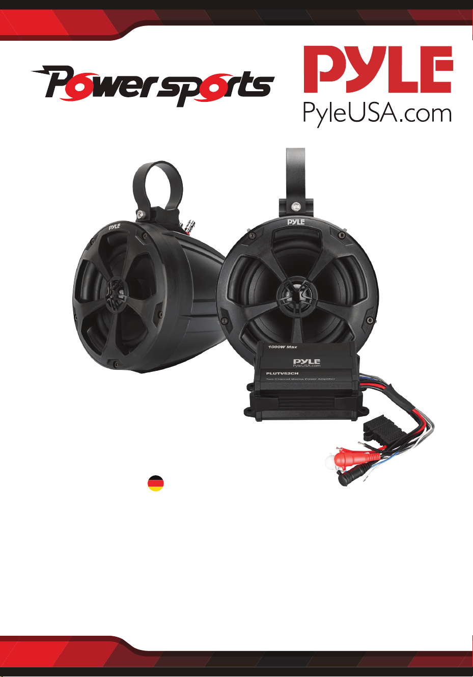
PowerSport Amp for ATV, UTV, 4x4, Jeep,Wired
RCA, for Boat Stereo Speaker & Other Watercraft
USER MANUAL
PLUTV52CH
ENG
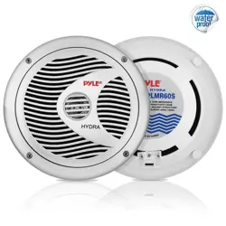
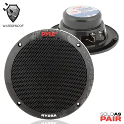
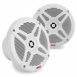
5.25” (16.5 cm) Waterproof Marine Speakers
+2 Ch. Rated Amplifier (1000W)

PRECAUTIONS
WIRING INSTRUCTIONS
This unit is designed for negative ground 12-14.50 Volts (DC) operation only.
Use speakers with an impedance of 4 Ohms
It would be subject to high temperatures, such as from direct sunlight or hot air
from the heater.
This power amplier employs a protection circuit to protect the transistors and
speakers if the amplier malfunctions. Do not attempt to test the protection
circuits by covering the heatsink or connecting improper loads.
If this unit is placed too close to the resources radio, an interference may occur.
In this case, separate the amplier from the car radio.
POWER CONNECTION
The battery terminal (BATT) must be connected directly to the positive terminal of
the vehicle battery to provide an adequate voltage source and minimize noise.
Connecting the battery terminal lead to any other point (such as the fuse block)
will reduce the power output and may cause noise and distortion. Use only #12
gauge or thicker (smaller gauge #) wire for this lead and connect it to the terminal
of the battery after all other wiring is completed.
GROUND CONNECTION
The ground terminal (GND) connection is also critical to the correct operation of
the amplier. Use a wire of the same gauge as the power connection (#8 or thicker)
and connect it between the ground terminal (GND) of the amplier and a metal
part of the vehicle close to the mounting location. This wire should be as short as
possible and any paint or rust at the grounding point should be scraped away to
provide a clean metal surface to which the end of the ground wire can be screwed
or bolted.
For safety reasons, keep the volume of your audio system moderate so that you
can still hear normal trac sounds in a reasonable distance.
Do not use the unit with a weak auto battery as its optimum performance
depends on a normal battery supply voltage.
When installing the unit horizontally, be sure not to cover the heatsink ns with
the oor carpet.
If your vehicle or boat is parked in direct sunlight and there is a considerable
rise in temperature inside the car, allow the unit to cool o before operation.
Avoid installing the unit where:
It would be subject to dust or dirt.
It would be exposed to rain or moisture.

REMOTE TURN-ON CONNECTION
The amplier is turned on by applying +12V to the remote turn-on terminal (REM).
The wire lead to this terminal should be connected to the "Auto-Antenna” lead
from the vehicle/or boat stereo resources which will provide the +12V only when
the stereo resources is turned on. If the car stereo does not provide an "Auto-An-
tenna” lead, the remote turn-on lead may be wired to an "Accessory" or "Radio"
terminal in the vehicle’s/or boat's fuse block. This will turn the amplier on and o
with the ignition key, regardless of whether the stereo resources is on or o.
The remote turn-on lead does not carry large currents. So #16 gauge wire may be
used for this application.
SPEAKER CONNECTIONS
Depending on the type and number of speakers used with the amplier wire them
to the speaker terminals as per the appropriate wiring diagram. For most applications
#18 gauge wire should be used for the speaker leads but in no case thinner than
#16 gauge. For leads is excess of 10 feet #12 gauge is recommended. When wiring
the speakers, pay careful attention to the polarity of the terminals on the speakers
and make certain they correspond to the polarity of the corresponding terminals
on the amplier. Do not ground any speaker leads to the chassis of the vehicle/or
boat.
GND (-) = GROUND CONNECTION
Connect the GND terminal to the chassis ground of your vehicle/or boat and
take care of best electric and mechanic contact. In doing so, drill a hole into the
vehicle/or boat chassis near the amplier then remove color, dirt or any other
substance from the ground point. Thereafter fasten the cable end with added ring
terminal by using a screw. Ensure that the ground connection is as short as possible
and that the cable diameter is sucient (min 4mm). Route the ground cables from
the radio and all other equipment parts, like equalizer, active crossover network or
other ampliers, to the same ground point.
OPERATION
After the amplier has been installed and all connectios have been made carefully
and securely, turn the radio on so that the amplier is switched on automatically.
After a short power-on period, the amplier reaches its full performance. Now turn
up the volume slowly using the volume control of the radio. If there is no sound or
only a distorted replay, switch o the radio immediately - the amplier will also
switch o automatically - and check if all connections have been made correctly.

+ 12V = POWER SUPPLY
Connect the BATT terminal to the positive pole of the battery with a lead cable and
add a fuse into the power cable in a distance of not more than 30 cm from the
battery. The lead cable’s diameter should be at least 4 mm for a length of 3 m and
6 mm for a length of 6 m.
REM (ON/OFF) REMOTE CONTROL
Connect the REM terminal to the automatic antenna connector of your vehicle/or
boat radio. Now when turning on and o your vehicle/or boat radio, the amplier
automatically switches ON and OFF. A cable diameter of 0.5mm is sucient.
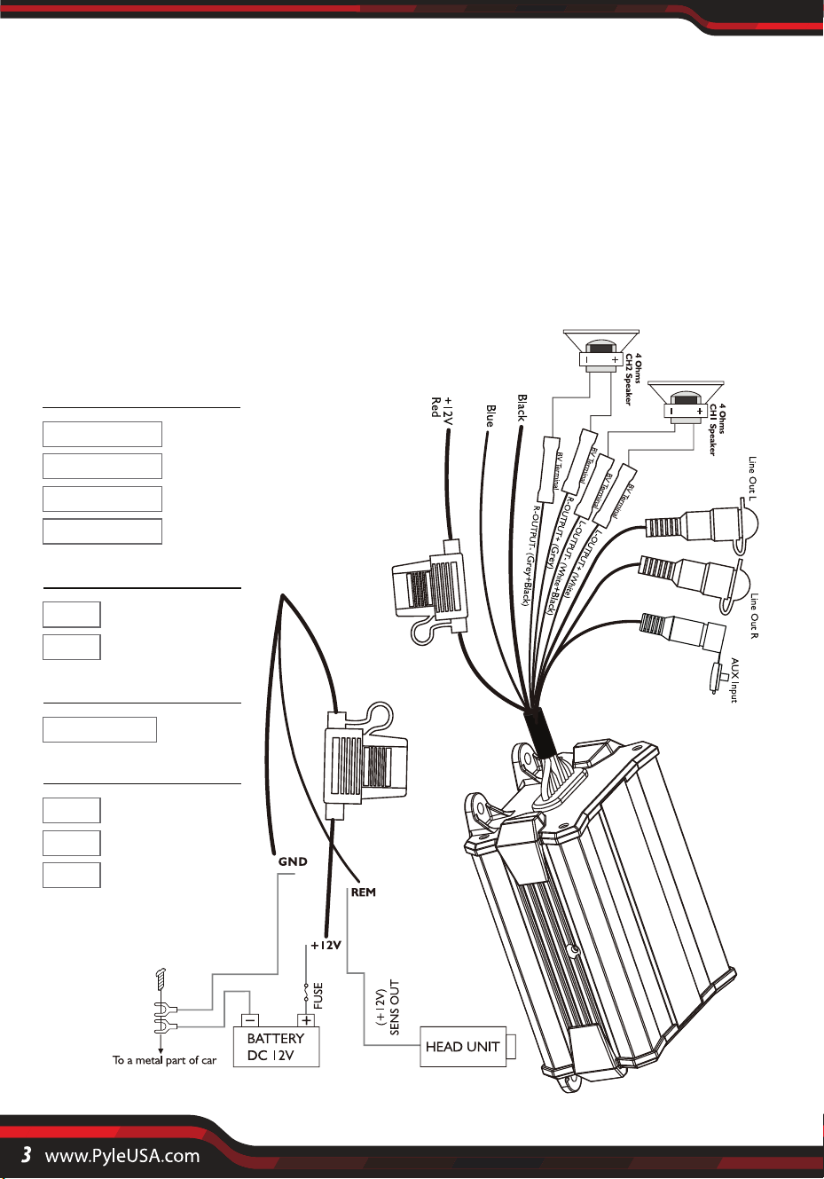
SPEAKERS CONNECTIONS
Speaker Output
Line Output
AUX Input
WhiteL-OUTPUT+
Black
AUX Input
White ( L )OUT
Red ( R )OUT
Red+12V
BlackGND
BlueREM
GreyR-OUTPUT+
Grey+BlackR-OUTPUT-
White+BlackL-OUTPUT-
Power
POWER CONNECTION LEADS

NOTES ON THE POWER SUPPLY
Connect the +12V power input lead only after all other leads have been connected.
Be sure to connect the ground wire of the unit securely to a metal part of the
vehicle/or boat.
Use the power supply lead with a fuse attached whose value is the same as original
fuse.
Use the specied amperage fuse. Use of a higher amperage fuse may cause serious
damage.
the unit is overheated.
the speaker terminals are short circuited.
REM: The unit is turned on by applying +12 Volts to this terminal. This terminal
does not draw heavy current like the tow Power Terminals so a thinner connecting
wire is acceptable. Standard 18 GAUGE is ne and the standard color is red. If the
radio is equipped with a Power Antenna control wire, it can drive this terminal.
If the Power Antenna wire is already in use, you can still splice into it. With this
method, the unit will turn ON automatically with the radio.
During a full power operation, Maximum current will run through the system.
Therefore, make sure that the leads to be connected to the +12V and GND
terminals of the unit respectively must be larger than 18-Gauge (AWG.18) proper
Bridged operation. If only mono signal is available, a "Y" adapter is required.
The connection cable is not connected correctly (=terminal +12V/GND/REM).
Ensure that all connections and mechanic contact and that the jacket has been
removed. The fuse is defective-pay attention to the correct value of a new fuse!
Loose or faulty connection may cause amplier malfunction
Place the fuse in the power supply lead as close as possible to the car battery.
FUSE REPLACEMENT
If the fuse blows, check the power connection and replace the fuse. If the fuse blows
again after replacement, there may be an internal malfunction. In this case, consult
your dealer.
This amplier is provided with a protection circuit which operates in the
following cases when:
No Function:
WARNING
HOW TO PROCEED IN CASE OF FAULTS
PROTECTION CIRCUIT

No Sound:
Speaker cable or speaker plug are not connected correctly.
The plus and minus wires of the speaker cable have contact, thus eliminate the
short circuit. If you use Pay attention only 4 ohm load speaker is allowed. No 2 ohm
or less impedance speaker connection is allowed.
Lay the signal, speaker and power cables separately with enough distance from
one another and also from each other car cable. If not possible, you can lay the
circuit and ground cable together with the serial cables. Audio and speaker cable
should be as far away from these as possible. The REM cable to the automatic
antenna output of the radio can be laid together with the signal cables.
Avoid ground loops by laying the ground wiring of all components to a center
point in a star-like way. you can nd the best central point in measuring the
voltage directly at the battery. Now compare this voltage value with the chosen
ground point and the (+) terminal of the amplier. If measured voltage is only
slightly dierent, you've found the correct central. Otherwise you have to look for
another point. You should measure with the ignition point for earth being switched
on and additionally switched on consumers (rear window heating and light).
Poor Sound Quality (Distortions):
All cables can source and create interference. The power cable and Cinch/RCA
audio cable are very prone to interference; the remote cables are less prone.
There is often interference caused by the generator (piping), ignition (cracking) or
other vehicle/or boat electronic parts. Most of these problems can be eliminated
by correct and careful cabling. In doing so, here are the following guidelines:
The speakers are overloaded therefore turn down the volume level and check the
volume control positions.
If there are noises from the car electrics, add an interference suppression choke
into the power wiring.
If there are humming noises, use thicker ground cables or add further ground
cables to the chassis.
If there are pickups from external electrical sources into the speaker cables, divide
the core leads and twist them together.
Use only a screened audio cable for the wiring between “low level in” of the
amplier and RCA or DIN output of the radio.
No Stereo Sound And A Weak Bass:
INTERFERENCE
Speaker cables (+) and (-) are mixed up, unit wired out of phase.

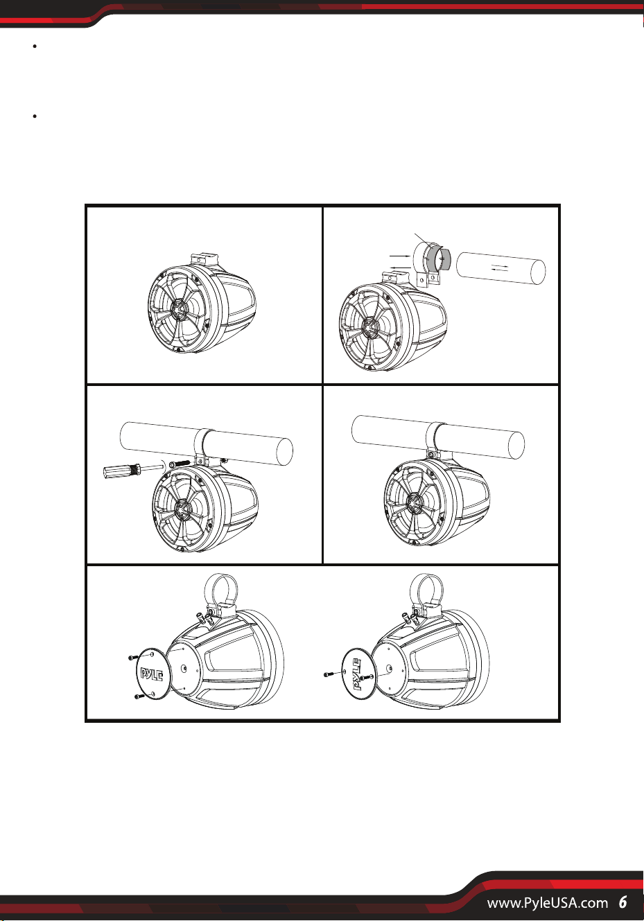
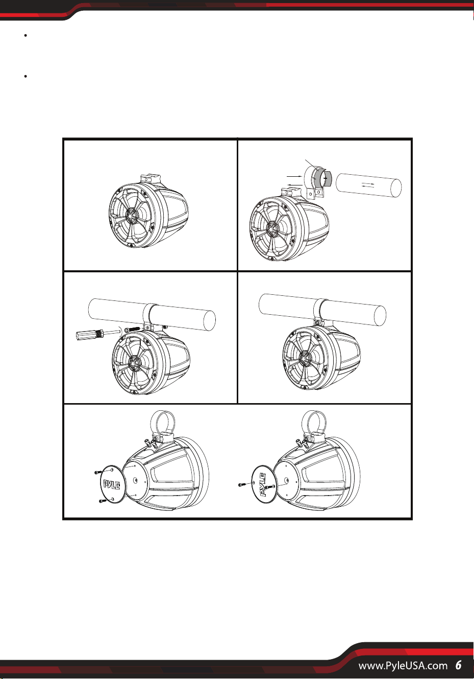
PLUTV52CH Speaker Installation
Speaker Mounting suggestion as below:
Auto Reconnection:
STEP 1 STEP 2
STEP 3
STEP 5
STEP 4
Rubber Pad
To reduce contact resistance and bad and loose contacts, please solder the cable
ends or use multi core cable ends, spade terminals or others. Gold Plated spade
terminal are free of corrosion and have the lowest contact resistance.
Should all these meaures be without any success, the use of a ground loop
isolator may solve the problem.
Step 1: Put the PLUTV52CH speaker in a safe place.
Step 2: Slide in the buckle with rubber pad attached to the bracket stand of the
speaker. Attach the set to the handle bar of vehicle/ship.
Step 3/4: Attach screw to lock the buckle.
Step5: Option for adjustable PYLE logo---Unbolted the screws rst, adjusting
logo direction, then re-x screws.

Features:
• Waterproof Rated Speakers
• Pro Audio Power Sports Amplier System Kit
• 2-Channel Marine Audio Amplier
• Marine Grade Rugged Construction
• Waterproof Rated & Weather-Resistant Connectors
• Integrated Power Wiring Harness
• Perfect for Custom Installations & Applications
• Ability to Connect & Stream Audio from External Devices
• Aux (3.5mm) Input
• Pre-Amp RCA Out to Any OEM/Factory-Made Block/Full-Range Amplier
• Speaker Wiring Connectivity
• Anti-Thump Turn-On
• Soft Turn On / O
• Overload & Power Protection Circuitry
• Used for Watercraft & Portable Mobile Vehicle Sound Systems
What’s in the Box:
• (2) 5.25” inches (13.3 cm) Marine Speakers
• (2) Speaker Connection Wires, 6.5' ft. (78“ inches) (198.1 cm)
• (2) 1.75” inches (4.4 cm) Aluminum Mounting Brackets
• (2) 2” inches (5 cm) Aluminum Mounting Brackets
• (2) 6.5”x 0.95" x 0.67" Inches (16.5 x 2.4 x 1.7 cm) Rubber Pads
• (2) 5.7”x 0.95" x 0.67" Inches (14.4 x 2.4 x 1.7 cm) Rubber Pads
• (2) 6x50mm (0.23”x1.96” inches) (0.6 x 5 cm) Hexagon Socket Head Cap Screws
• (2) Stainless Steel Nuts
• Compact Marine Amp
• (4) Butt Connector 16-22AWG
• Screw Bag
• (4) Nylon Wire Straps

Amplier Technical Specs:
• Amplier Type: 2-Ch. Audio Component
• Power Output: 1000 Watt MAX
• 2x 50 Watts RMS @ 4 Ohm
• 2x 150 Watts MAX @ 4Ohm
• Marine Grade IP-45 Rating
• T.H.D:< 1%
• S/N Ratio: > 80dB
• Channel Separation: > 65dB
• Amp Freq. Response: 20Hz- 20 kHz
• Fuse: 15A
• Power: DC 12V
• Amp Dimensions (L x W x H):
6" x 3.86” x 2.36” -inch (15.2 x 9.8 x 5.9 cm)
Marine Speaker Technical Specs:
• Power Output: 1000 Watts
• Marine Grade Waterproof Rating: IP-X45
• Speaker Size: 5.25” -inch (13.3 cm) (Each)
• Speaker Style: Passive Speakers
• Speaker Type: Polypropylene Cone, Butyl Rubber Surround (x2)
• Tweeter Type: Neodymium Dome (x2)
• Frequency Response: 80Hz-20kHz
• Impedance: 4 Ohm
• Magnet Type: 24 oz. Circuit
• Mid-Woofer Voice Coil Type: 1“ inch (2.5 cm), Aluminum
• Sensitivity: 88 dB +/- 2 dB @ 1M/1W
• Universal Mounting Brackets Roll-Bar /
Roll-Cage Diameter: 1.75” ~ 2.0”-inch (4.4 ~ 5 cm)
• Speaker Dimensions:
6.5"x 7.1” x 9.5” -inch (16.5 x 18 x 24.1 cm), with Bracket (-Each)
This products can expose you to a chemical or group of chemicals, which
may include “Di (2-ethylhexyl) phthalate (DEHP)” which is known in the
state of California to cause cancer, birth defects, or other reproductive harm.
For more info, go to https:/www.p65warnings.ca.gov/.
WARNING:


Amplificador PowerSport para ATV, UTV, 4x4, Jeep, RCA con
cable, para altavoz estéreo de barco y otras embarcaciones
Maual del usuario
PLUTV52CH
Altavoces marinos impermeables de 5,25" (16.5 cm)
+ Amplificador nominal de 2 canales (1000 W)
SPA

PRECAUCIONES
INSTRUCCIONES DE CABLEADO
Esta unidad está diseñada para funcionar únicamente con tierra negativa de 12 a
14,50 voltios (CC).
Utilice altavoces con una impedancia de 4 ohmios
Estaría sujeto a altas temperaturas, como la luz solar directa o el aire caliente del
calentador.
Este amplicador de potencia emplea un circuito de protección para proteger los
transistores y los altavoces en caso de que el amplicador no funcione correctamente.
No intente probar los circuitos de protección cubriendo el disipador de calor o
conectando cargas inadecuadas.
Si esta unidad se coloca demasiado cerca de la radio de recursos, puede producirse una
interferencia. En este caso, separe el amplicador de la radio del automóvil.
CONEXIÓN DE ALIMENTACIÓN
El terminal de la batería (BATT) debe conectarse directamente al terminal positivo de la
batería del vehículo para proporcionar una fuente de voltaje adecuada y minimizar el
ruido. Conectar el cable del terminal de la batería a cualquier otro punto (como el bloque
de fusibles) reducirá la potencia de salida y puede causar ruido y distorsión. Use solo un
cable de calibre # 12 o más grueso (calibre más pequeño #) para este cable y conéctelo al
terminal de la batería después de que se complete todo el resto del cableado.
CONEXIÓN A TIERRA
La conexión del terminal de tierra (GND) también es fundamental para el correcto
funcionamiento del amplicador. Use un cable del mismo calibre que la conexión de
alimentación (# 8 o más grueso) y conéctelo entre el terminal de tierra (GND) del
amplicador y una parte metálica del vehículo cerca del lugar de montaje. Este cable debe
ser lo más corto posible y cualquier pintura u óxido en el punto de conexión a tierra debe
rasparse para proporcionar una supercie metálica limpia a la que se pueda atornillar o
atornillar el extremo del cable de tierra.
Por razones de seguridad, mantenga el volumen de su sistema de audio moderado para
que pueda escuchar los sonidos normales del tráco a una distancia razonable.
No utilice la unidad con una batería automática débil, ya que su rendimiento óptimo
depende de un voltaje de alimentación de batería normal.
Al instalar la unidad horizontalmente, asegúrese de no cubrir las aletas del disipador de
calor con la alfombra del piso.
Si su vehículo o embarcación está estacionado bajo la luz solar directa y hay un aumento
considerable de la temperatura dentro del automóvil, deje que la unidad se enfríe antes
de funcionar.
Evite instalar la unidad donde:
Estaría sujeto a polvo o suciedad.
Estaría expuesto a la lluvia o a la humedad.

CONEXIÓN DE ENCENDIDO REMOTO
El amplicador se enciende aplicando +12 V al terminal de encendido remoto (REM). El
cable de este terminal debe conectarse al cable de "Antena automática" de los recursos
estéreo del vehículo o embarcación, que proporcionará +12 V solo cuando se enciendan
los recursos estéreo. Si el estéreo del automóvil no proporciona un cable "Auto-Antena", el
cable de encendido remoto puede estar conectado a un terminal de "Accesorio" o "Radio"
en el bloque de fusibles del vehículo / o embarcación. Esto encenderá y apagará el
amplicador con la llave de encendido, independientemente de si los recursos estéreo
están encendidos o apagados. El cable de encendido remoto no transporta grandes
corrientes. Por lo tanto, se puede usar alambre de calibre # 16 para esta aplicación.
CONEXIONES DE ALTAVOCES
Dependiendo del tipo y la cantidad de altavoces utilizados con el amplicador, conéctelos
a los terminales de los altavoces según el diagrama de cableado correspondiente. Para la
mayoría de las aplicaciones, se debe usar un cable de calibre # 18 para los cables de los
altavoces, pero en ningún caso más delgado que el calibre # 16. Para los cables que exceden
los 10 pies, se recomienda el calibre # 12. Al cablear los altavoces, preste mucha atención a
la polaridad de los terminales de los altavoces y asegúrese de que correspondan a la
polaridad de los terminales correspondientes del amplicador. No conecte a tierra ningún
cable de altavoz al chasis del vehículo o embarcación.
GND (-) = CONEXIÓN A TIERRA
Conecte el terminal GND a la tierra del chasis de su vehículo / embarcación y asegúrese de
que tenga el mejor contacto eléctrico y mecánico. Al hacerlo, taladre un oricio en el chasis
del vehículo o barco cerca del amplicador y luego elimine color (pintura), suciedad o
cualquier otra sustancia del punto de tierra. A continuación, je el extremo del cable con el
terminal de anillo agregado con un tornillo. Asegúrese de que la conexión a tierra sea lo
más corta posible y que el diámetro del cable sea suciente (mínimo 4 mm). Enrute los
cables de tierra desde la radio y todas las demás partes del equipo, como el ecualizador, la
red de cruce activa u otros amplicadores, al mismo punto de tierra.
OPERACIÓN
Una vez que se haya instalado el amplicador y se hayan realizado todas las conexiones
de forma cuidadosa y segura, encienda la radio para que el amplicador se encienda
automáticamente. Después de un breve período de encendido, el amplicador alcanza
su máximo rendimiento. Ahora sube el volumen lentamente usando el control de volumen
de la radio. Si no hay sonido o solo una repetición distorsionada, apague la radio
inmediatamente (el amplicador también se apagará automáticamente) y verique si todas
las conexiones se han realizado correctamente.

+ 12V = FUENTE DE ALIMENTACIÓN
Conecte el terminal BATT al polo positivo de la batería con un cable conductor y agregue
un fusible en el cable de alimentación a una distancia de no más de 30 cm de la batería. El
diámetro del cable conductor debe ser de al menos 4 mm para una longitud de 3 m y de 6
mm para una longitud de 6 m.
MANDO A DISTANCIA REM (ON/OFF)
Conecte el terminal REM al conector de antena automática de la radio de su vehículo o
barco. Ahora, al encender y apagar la radio de su vehículo o barco, el amplicador se
enciende y apaga automáticamente. Un diámetro de cable de 0.Smm2 es suciente.
SPEAKERS CONNECTIONS
Salida de altavoz
línea de salida
Entrada AUX
BlancoL-OUTPUT+
Negro
AUX Input
Blanco ( L )OUT
Rojo ( R )OUT
Rojo+12V
NegroGND
AzulREM
GrisR-OUTPUT+
Gris+NegroR-OUTPUT-
Blanco+NegroL-OUTPUT-
conexión
Cables de conexión de alimentación

NOTAS SOBRE LA FUENTE DE ALIMENTACIÓN
Conecte el cable de entrada de alimentación de + 12 V solo después de que se hayan
conectado todos los demás cables.
Asegúrese de conectar el cable de tierra de la unidad de forma segura a una parte metálica
del vehículo o embarcación.
Utilice el cable de la fuente de alimentación con un fusible conectado cuyo valor sea el
mismo que el fusible original.
Utilice el fusible de amperaje especicado. El uso de un fusible de mayor amperaje puede
causar daños graves.
La unidad está sobrecalentada.
Los terminales de los altavoces están en cortocircuito.
REM: La unidad se enciende aplicando +12 voltios a este terminal. Este terminal no
consume corriente pesada como los terminales de alimentación de remolque, por lo que es
aceptable un cable de conexión más delgado. El calibre 18 estándar está bien y el color
estándar es rojo. Si la radio está equipada con un cable de control de antena de alimentación,
puede controlar este terminal. Si el cable de la antena de alimentación ya está en uso, aún
puede empalmarlo. Con este método, la unidad se encenderá automáticamente con la radio.
Durante una operación a plena potencia, la corriente máxima correrá a través del sistema.
Por lo tanto, asegúrese de que los cables que se conectarán a los terminales + 12 V y GND
de la unidad, respectivamente, deben ser más grandes que el funcionamiento correcto del
puente de calibre 18 (AWG.18). Si solo hay señal mono disponible, se requiere un adaptador
"Y".
El cable de conexión no está conectado correctamente (=terminal+12V/GND/REM).
Asegúrese de que se hayan quitado todas las conexiones y el contacto mecánico y que se
haya quitado la camisa. El fusible está defectuoso: ¡preste atención al valor correcto de un
fusible nuevo!
Una conexión suelta o defectuosa puede causar un mal funcionamiento del amplicador
Coloque el fusible en el cable de la fuente de alimentación lo más cerca posible de la batería
del automóvil.
REEMPLAZO DE FUSIBLES
Si el fusible se funde, verique la conexión de alimentación y reemplace el fusible. Si el
fusible vuelve a fundirse después de la sustitución, puede haber un mal funcionamiento
interno. En este caso, consulte a su distribuidor.
Este amplicador está provisto de un circuito de protección que funciona en los
siguientes casos cuando:
Sin función:
ADVERTENCIA
CÓMO PROCEDER EN CASO DE AVERÍAS
CIRCUITO DE PROTECCIÓN

Sin sonido:
El cable del altavoz o el enchufe del altavoz no están conectados correctamente.
Los cables positivo y negativo del cable del altavoz tienen contacto, lo que elimina el
cortocircuito. Si usa Preste atención, solo se permite un altavoz de carga de 4 ohmios. No
se permite una conexión de altavoz de 2 ohmios o menos impedancia.
Coloque los cables de señal, altavoz y alimentación por separado con suciente distancia
entre sí y también entre sí del cable del automóvil. Si no es posible, puede tender el circuito
y el cable de tierra junto con los cables serie. El cable de audio y del altavoz debe estar lo
más lejos posible de ellos. El cable REM a la salida automática de la antena de la radio se
puede tender junto con los cables de señal.
Evite los bucles de tierra colocando el cableado de tierra de todos los componentes en un
punto central en forma de estrella. Puede encontrar el mejor punto central para medir el
voltaje directamente en la batería. Ahora compare este valor de voltaje con el punto de tierra
elegido y el terminal (+) del amplicador. Si el voltaje medido es solo ligeramente diferente,
ha encontrado la central correcta. De lo contrario, hay que buscar otro punto. Debe medir
con el punto de encendido para la conexión a tierra y los consumidores adicionales encendi-
dos (calefacción y luz de la ventana trasera).
Mala calidad de sonido (distorsiones):
Todos los cables pueden originar y crear interferencias. El cable de alimentación y el cable
de audio Cinch/RCA son muy propensos a interferencias; Los cables remotos son menos
propensos. A menudo hay interferencias causadas por el generador (tuberías), el encendi-
do (agrietamiento) u otras partes electrónicas del vehículo o embarcación. La mayoría de
estos problemas se pueden eliminar con un cableado correcto y cuidadoso. Al hacerlo,
aquí están las siguientes pautas:
Los altavoces están sobrecargados, por lo tanto, baje el nivel de volumen y verique las
posiciones de control de volumen.
Si hay ruidos del sistema eléctrico del automóvil, agregue un estrangulador de supresión de
interferencias en el cableado de alimentación.
Si hay zumbidos, utilice cables de tierra más gruesos o agregue más cables de tierra al chasis.
Si hay captaciones de fuentes eléctricas externas en los cables de los altavoces, divida los
cables del núcleo y gírelos juntos.
Utilice únicamente un cable de audio con pantalla para el cableado entre la entrada de
"bajo nivel" del amplicador y la salida RCA o DIN de la radio.
Sin sonido estéreo y con un bajo débil:
INTERFERENCIA
Los cables de los altavoces(+) y (-) están mezclados, la unidad está desfasada.

PLUTV52CH Instalación de altavoces
Sugerencia de montaje de altavoces de la siguiente manera:
Reconexión automática:
PASO 1 PASO 2
PASO 3
PASO 5
PASO 4
Rubber Pad
Para reducir la resistencia de contacto y los contactos defectuosos y sueltos, suelde los
extremos de los cables o utilice extremos de cables multipolares, terminales de pala u
otros. Los terminales de pala chapados en oro están libres de corrosión y tienen la
resistencia de contacto más baja.
En caso de que todas estas medidas no tengan éxito, el uso de un aislador de bucle de
tierra puede resolver el problema.
Paso 1: Coloque el altavoz PLUTV52CH en un lugar seguro.
Paso 2: Deslice la hebilla con la almohadilla de goma unida al soporte del altavoz.
Fije el juego al manillar del vehículo/barco.
Paso 3/4: Coloque el tornillo para bloquear la hebilla.
Paso 5: Opción para el logotipo PYLE ajustable---Desatornille primero los tornillos,
ajuste la dirección del logotipo y luego vuelva a jar los tornillos.

Funciones:
• Altavoces resistentes al agua
• Kit de sistema de amplicador de deportes de potencia de audio profesional
• Amplicador de audio marino de 2 canales
• Construcción robusta de grado marino
• Conectores resistentes al agua y a la intemperie
• Arnés de cableado eléctrico integrado
• Perfecto para instalaciones y aplicaciones personalizadas
• Capacidad para conectarse y transmitir audio desde dispositivos externos
• Entrada auxiliar (3,5 mm)
• Salida RCA de preamplicador a cualquier amplicador OEM/de bloque fabricado en
fábrica/amplicador de rango completo
• Conectividad de cableado de altavoces
• Encendido anti-golpe
• Encendido/apagado suave
• Circuitos de protección contra sobrecarga y energía
• Se utiliza para sistemas de sonido de embarcaciones y vehículos móviles portátiles
Contenido de la caja:
• (2) Altavoces marinos de 5,25" pulgadas
• (2) Cables de conexión de altavoces, 6.5' ft. (78“ inches) (198.1 cm)
• (2) Soportes de montaje de aluminio de 1.75" (4.4 cm)
• (2) Soportes de montaje de aluminio de 2" (5 cm)
• (2) Almohadillas de goma de 6.5" x 0.95" x 0.67" pulgadas (16.5 x 2.4 x 1.7 cm)
• (2) Almohadillas de goma de 5.7" x 0.95" x 0.67" pulgadas (14.4 x 2.4 x 1.7 cm)
• (2) Tornillos de cabeza hueca hexagonal de 6x50 mm (0.23”x1.96” inches) (0.6 x 5 cm)
• (2) Tuercas de acero inoxidable
• Amplicador marino compacto
• (4) Conector a tope 16-22AWG
• Bolsa de rosca
• (4) Correas de alambre de nailon

Especicaciones técnicas del amplicador:
• Tipo de amplicador: componente de audio de 2 canales
• Potencia de salida: 1000 vatios máx.
• 2 x 50 vatios RMS@ 4 ohmios
• 2 x 150 vatios MAX @ 4 Ohm
• Clasicación IP-45 de grado marino
• T.H.D:1%
• Relación señal/ruido: 80dB
• Separación de canales:: 65dB
• Respuesta de frecuencia de amperaje: 20 Hz- 20 kHz
• Fusible: 15A
• Alimentación: DC 12V
• Dimensiones del amperio (largo x ancho x alto):
6" x 3.86" x 2.36" -pulgadas (15.2 x 9.8 x 5.9 cm)
Especicaciones técnicas del altavoz marino:
• Potencia de salida: 1000 vatios
• Grado marino Grado de impermeabilidad: IP-X45
• Tamaño del altavoz: 5,25" pulgadas (13.3 cm) (cada uno)
• Estilo de altavoz: altavoces pasivos
• Tipo de altavoz: cono de polipropileno, borde de caucho butílico (x2)
• Tipo de tweeter: Cúpula de neodimio (x2)
• Respuesta de frecuencia: 80Hz-20kHz
• Impedancia: 4 Ohm
• Tipo de imán: 24 oz. Circuito
• Tipo de bobina de voz de woofer medio: 1” pulgada (2.5 cm), aluminio
• Sensibilidad: 88 dB+/- 2 dB@ 1M/1 W
• Soportes de montaje universales Roll-Bar/Roll-Cage Diámetro:
1.75 "~ 2.0" -pulgadas (4.4 ~ 5 cm)
• Dimensiones del altavoz: 6.5" x 7.1" x 9.5" pulgadas
(16.5 x 18 x 24.1 cm), con soporte (-cada uno)
Este producto puede exponerlo a un químico o grupo de químicos que pueden incluir
Di (2 ethiexil) ftalato (DEHP) que en el estado de California se reconoce como un
agente que causa cáncer, defectos de nacimiento u otros problemas reproductivos.
Para más información visite: www.P65warnings.ca.gov
ADVERTENCIA:


Amplificateur Powersport pour ATV, UTV, 4x4, Jeep, RCA câblé,
pour haut-parleur stéréo de bateau et autres embarcations.
GUIDE D’UTILISATION
PLUTV52CH
Haut-parleurs marins étanches de 5,25 pouces (16.5 cm)
Amplificateur +2 Ch.Rated (1000W)
FRE

PRÉCAUTIONS
INSTRUCTIONS DE C BLAGE
Cet appareil est conçu pour fonctionner uniquement avec une masse négative de 12 à
14,50 volts (DC).
Utilisez des haut-parleurs d'une impédance de 4 Ohms.
Il serait soumis à des températures élevées, telles que la lumière directe du soleil ou l'air
chaud du chauage.
Cet amplicateur de puissance utilise un circuit de protection pour protéger les
transistors et les enceintes en cas de dysfonctionnement de l'amplicateur. Ne pas
essayer de tester les circuits de protection en couvrant le dissipateur thermique ou en
connectant des charges inappropriées.
Si cet appareil est placé trop près d'une radio de ressources, des interférences peuvent
se produire. Dans ce cas, séparez l'amplicateur de l'autoradio.
BRANCHEMENT ÉLECTRIQUE
La borne de la batterie (BATT) doit être connectée directement à la borne positive de la
batterie du véhicule an de fournir une source de tension adéquate et de minimiser les
bruits. La connexion du l de la borne de la batterie à tout autre point (tel que le bloc de
fusibles) réduira la puissance de sortie et peut causer du bruit et de la distorsion. N'utilisez
que du l de calibre 12 ou plus épais (plus petit numéro de calibre) pour ce l et connect-
ez-le à la borne de la batterie une fois que tous les autres câblages sont terminés.
CONNEXION À LA TERRE
La connexion à la borne de terre (GND) est également essentielle au bon fonctionnement
de l'amplicateur. Utilisez un l de même calibre que la connexion d'alimentation (#8 ou
plus épais) et connectez-le entre la borne de terre (GND) de l'amplicateur et une partie
métallique du véhicule proche de l'emplacement de montage. Ce l doit être aussi court
que possible et toute peinture ou rouille au point de mise à la terre doit être grattée pour
obtenir une surface métallique propre à laquelle l'extrémité du l de mise à la terre peut
être vissée ou boulonnée.
Pour des raisons de sécurité, maintenez le volume de votre système audio à un niveau
modéré an de pouvoir entendre les bruits normaux de la circulation à une distance
N'utilisez pas l'appareil avec une batterie faible, car ses performances optimales
dépendent d'une tension d'alimentation normale.
Lors de l'installation horizontale de l'appareil, veillez à ne pas recouvrir les ailettes du
dissipateur thermique avec le tapis de sol.
Si votre véhicule ou votre bateau est garé en plein soleil et que la température
augmente considérablement à l'intérieur du véhicule, laissez l'appareil refroidir avant
de l'utiliser.
Évitez d'installer l'appareil dans un endroit où:
Il serait exposé à la poussière ou à la saleté.
Il serait exposé à la pluie ou à l'humidité.

CONNEXION DE LA MISE EN MARCHE A DISTANCE
L'amplicateur est mis en marche en appliquant + 12V à la borne de mise en marche à
distance (REM). Le l de cette borne doit être connecté au l de l'antenne automatique du
véhicule ou de la chaîne stéréo du bateau, qui fournira le +12V uniquement lorsque la
chaîne stéréo est allumée. Si l'autoradio ne fournit pas de l "Antenne auto", le l de mise en
marche à distance peut être câblé à une borne "Accessoire" ou "Radio" dans le bloc de
fusibles du véhicule ou du bateau. Cela permet d'allumer et d'éteindre l'amplicateur avec
la clé de contact, que les ressources stéréo soient allumées ou éteintes. Le l de mise sous
tension à distance ne transporte pas de courants importants. Un l de calibre 16 peut
donc être utilisé pour cette application.
CONNEXIONS DES HAUT-PARLEURS
Selon le type et le nombre de haut-parleurs utilisés avec l'amplicateur, raccordez-les aux
bornes des haut-parleurs conformément au schéma de câblage approprié. Pour la plupart
des applications, un l de calibre 18 doit être utilisé pour les câbles des haut-parleurs, mais
en aucun cas un l plus n que le calibre 16. Pour les ls de plus de 3 mètres, il est
recommandé d'utiliser du l de calibre 12. Lors du câblage des enceintes, faites attention
à la polarité des bornes des enceintes et assurez-vous qu'elles correspondent à la polarité
des bornes correspondantes de l'amplicateur. Ne mettez pas les ls des enceintes à la
terre sur le châssis du véhicule ou du bateau.
GND (-)=CONNEXION À LA TERRE
Connectez la borne GND à la masse du châssis de votre véhicule/bateau et veillez à ce qu'il
n'y ait pas de contact électrique ou mécanique. Pour ce faire, percez un trou dans le châssis
du véhicule ou du bateau près de l'amplicateur, puis enlevez la couleur, la saleté ou toute
autre substance du point de mise à la terre. Fixez ensuite l'extrémité du câble avec la borne
annulaire ajoutée à l'aide d'une vis. Veillez à ce que la connexion à la terre soit aussi courte
que possible et que le diamètre du câble soit susant (min. 4 mm). Acheminez les câbles
de mise à la terre de la radio et de tous les autres éléments de l'équipement, tels que
l'égaliseur, le réseau de croisement actif ou d'autres amplicateurs, vers le même point de
mise à la terre.
FONCTIONNEMENT
Une fois que l'amplicateur a été installé et que tous les raccordements ont été eectués
avec soin et en toute sécurité, allumez la radio de manière à ce que l'amplicateur se mette
automatiquement en marche. Après une courte période de mise sous tension, l'amplicateur
atteint sa pleine puissance. Augmentez alors lentement le volume à l'aide du bouton de
réglage du volume de la radio. S'il n'y a pas de son ou seulement une reproduction déformée,
éteignez immédiatement la radio - l'amplicateur s'éteindra également automatiquement -
et vériez si toutes les connexions ont été eectuées correctement.

TÉLÉCOMMANDE REM (MARCHE/ARRÊT)
Connectez la borne REM au connecteur de l'antenne automatique de votre véhicule/radio
de bateau. Ainsi, lorsque vous allumez et éteignez la radio de votre véhicule ou de votre
bateau, l'amplicateur s'allume et s'éteint automatiquement. Un diamètre de câble de 0,5
mm2 est susant.
CONNEXIONS DES HAUT-PARLEURS
Sortie haut-parleur
Sortie ligne
Rouge
BlancL-OUTPUT+
Noir
AUX Input
Blanc ( L )OUT
Rouge ( R )OUT
Rouge+12V
NoirGND
BleuREM
GrisR-OUTPUT+
Gris+NoirR-OUTPUT-
Blanc+NoirL-OUTPUT-
Alimentation
POWER CONNECTION LEADS
+ 12V = ALIMENTATION
Connectez la borne BATT au pôle positif de la batterie à l'aide d'un câble et ajoutez
un fusible dans le câble d'alimentation à une distance maximale de 30 cm de la
batterie. Le diamètre du câble doit être d'au moins 4 mm' pour une longueur de 3
m et de 6 mm' pour une longueur de 6 m.

NOTES SUR L'ALIMENTATION ÉLECTRIQUE
Ne branchez le l d'entrée +12V qu'après avoir branché tous les autres ls.
Veillez à bien connecter le l de terre de l'appareil à une partie métallique du véhicule ou
du bateau.
Utilisez le l d'alimentation avec un fusible attaché dont la valeur est la même que celle
du fusible d'origine.
Utilisez le fusible d'ampérage spécié. L'utilisation d'un fusible d'un ampérage supérieur
peut entraîner de graves dommages.
l'appareil est surchaué
les bornes du haut-parleur sont court-circuitées.
REM: REM : L'appareil est mis sous tension en appliquant une tension de +12 volts à cette
borne. Cette borne ne tire pas un courant important comme les bornes d'alimentation de
remorquage, de sorte qu'un l de connexion plus n est acceptable. Un l standard de
calibre 18 convient et la couleur standard est le rouge. Si la radio est équipée d'un l de
commande d'antenne électrique, il peut alimenter cette borne. Si le l de l'antenne
d'alimentation est déjà utilisé, vous pouvez toujours y faire une épissure. Avec cette
méthode, l'appareil s'allumera automatiquement avec la radio.
Lors d'un fonctionnement à pleine puissance, le système est parcouru par un courant
maximal. Par conséquent, veillez à ce que les ls à connecter aux bornes +12V et GND de
l'appareil soient d'un calibre supérieur à 18 (AWG.18) pour un fonctionnement en pont.
Si seul un signal mono est disponible, un adaptateur "Y" est nécessaire.
Le câble de connexion n'est pas branché correctement (=terminal + 12V/GND/REM).
Assurez-vous que toutes les connexions et tous les contacts mécaniques sont en place et
que la gaine a été enlevée. Le fusible est défectueux - faites attention à la valeur correcte
d'un nouveau fusible!
Une connexion lâche ou défectueuse peut entraîner un dysfonctionnement de
l'amplicateur.
Placez le fusible dans le câble d'alimentation aussi près que possible de la batterie de la
voiture.
REMPLACEMENT DU FUSIBLE
Si le fusible saute, vériez la connexion électrique et remplacez le fusible. Si le fusible
saute à nouveau après avoir été remplacé, il se peut qu'il y ait un dysfonctionnement
interne.
Cet amplicateur est équipé d'un circuit de protection qui fonctionne dans les cas
suivants :
Pas de fonctionnement:
ATTENTION
COMMENT PROCÉDER EN CAS DE PANNE
CIRCUIT DE PROTECTION

Pas de son:
Le câble ou la che de l'enceinte n'est pas correctement connecté.
Les ls plus et moins du câble de l'enceinte sont en contact, ce qui élimine le court-circuit.
Si vous utilisez des enceintes, faites attention : seules les enceintes à charge de 4 ohms sont
autorisées. Aucune connexion de haut-parleur d'une impédance de 2 ohms ou moins n'est
autorisée.
Posez les câbles de signal, de haut-parleur et d'alimentation séparément, à une distance
susante les uns des autres et également de chaque câble de voiture. Si ce n'est pas
possible, vous pouvez poser le câble de circuit et de masse avec les câbles série. Les câbles
audio et de haut-parleurs doivent être aussi éloignés que possible de ces derniers. Le câble
REM vers la sortie de l'antenne automatique de la radio peut être posé avec les câbles de
signal.
Évitez les boucles de masse en plaçant les câbles de masse de tous les composants en
étoile vers un point central. Vous pouvez trouver le meilleur point central en mesurant la
tension directement sur la batterie. Comparez ensuite cette valeur de tension avec le point
de masse choisi et la borne (+) de l'amplicateur. Si la tension mesurée n'est que légère-
ment diérente, vous avez trouvé le bon point central. Dans le cas contraire, vous devez
chercher un autre point. Vous devez mesurer avec le point d'allumage de la terre allumé et
les consommateurs supplémentaires allumés (chauage et éclairage de la lunette arrière).
Mauvaise qualité sonore (distorsions):
Tous les câbles peuvent être à l'origine d'interférences. Le câble d'alimentation et le
câble audio Cinch/RCA sont très sensibles aux interférences ; les câbles de la télécom-
mande le sont moins. Il y a souvent des interférences causées par le générateur
(tuyauterie), l'allumage (ssuration) ou d'autres pièces électroniques du véhicule ou du
bateau. La plupart de ces problèmes peuvent être éliminés par un câblage correct et
soigneux. Pour ce faire, il convient de suivre les lignes directrices suivantes :
Les enceintes sont surchargées, il faut donc baisser le volume et vérier la position des
commandes de volume.
En cas de bruits provenant du système électrique de la voiture, ajoutez une self
antiparasite dans le câblage d'alimentation.
En cas de bourdonnement, utilisez des câbles de masse plus épais ou ajoutez des câbles
de masse supplémentaires au châssis.
Si des sources électriques externes sont présentes dans les câbles des haut-parleurs,
divisez les ls de l'âme et torsadez-les ensemble.
Utilisez uniquement un câble audio blindé pour le câblage entre l'"entrée bas niveau" de
l'amplicateur et la sortie RCA ou DIN de la radio.
Pas de son stéréo et des basses faibles
INTERFÉRENCES
Les câbles des enceintes (+) et (-) sont mélangés, l'appareil est déphasé.
PLUTV52CH Installation des enceintes
Suggestion de montage de l'enceinte comme ci-dessous:
Reconnexion automatique:
ÉTAPE 1 ÉTAPE 2
ÉTAPE 3
ÉTAPE 5
ÉTAPE 4
Coussinet en caoutchouc
Pour réduire la résistance de contact et les mauvais contacts, soudez les extrémités du
câble ou utilisez des extrémités de câble à plusieurs conducteurs, des cosses ou autres.
Les cosses plaquées or sont exemptes de corrosion et ont la plus faible résistance de
contact.
Si toutes ces mesures restent sans eet, l'utilisation d'un isolateur de boucle de terre
peut résoudre le problème.
Étape 1: Placez l'enceinte PLUTV52CH dans un endroit sûr.
Étape 2: Glissez la boucle avec le tampon en caoutchouc attaché au support de l'enceinte.
Attachez l'ensemble au guidon du véhicule/navire.
Étape 3/4: Fixer la vis pour verrouiller la boucle.
Étape 5: Option pour l'ajustement du logo PYLE : dévisser d'abord les vis, ajuster la directio
du logo, puis xer à nouveau les vis.

Caractéristiques:
• Haut-parleurs étanches
• Kit de système d'amplication Pro Audio Power Sports
• Amplicateur audio marin à 2 canaux
• Construction robuste de qualité marine
• Connecteurs étanches et résistants aux intempéries
• Faisceau de câblage intégré
• Parfait pour les installations et applications personnalisées
• Possibilité de connecter et de diuser de l'audio à partir d'appareils externes
• Entrée auxiliaire (3,5 mm)
• Sortie RCA pré-ampliée pour tout bloc ou amplicateur d'origine ou d'usine
• Connectivité du câblage des haut-parleurs
• Mise en marche anti-bélier
• Mise en marche/arrêt progressif
• Circuit de protection contre les surcharges et l'alimentation
• Utilisé pour les systèmes de sonorisation des bateaux et des véhicules mobiles portables
Contenu de la boîte:
• (2) Haut-parleurs marins de 5,25 pouces (13.3 cm)
• (2) Fils de connexion de haut-parleur, 6,5' ft. (78“ inches) (198.1 cm)
• (2) Supports de montage en aluminium de 1,75 pouces (4.4 cm)
• (2 supports de montage en aluminium de 2 pouces (5 cm)
• (2 tampons en caoutchouc de 6,5" x 0,95" x 0,67" pouces (16.5 x 2.4 x 1.7 cm)
• (2) Coussinets en caoutchouc de 5,7" x 0,95" x 0,67" pouces (14.4 x 2.4 x 1.7 cm)
• (2 vis à tête cylindrique hexagonale de 6x50 mm (0.23”x1.96” inches) (0.6 x 5 cm)
• (2 écrous en acier inoxydable
• Amplicateur marin compact
• (4) Connecteur en bout 16-22AWG
• Sac de vis
• (4) Sangles en nylon

Caractéristiques techniques de l'amplicateur:
• Type d'amplicateur : Composant audio à 2 canaux
• Puissance de sortie : 1000 Watt MAX
• 2 x 50 Watts RMS @40hm
• 2 x 150 Watts MAX @ 40hm
• Classe marine IP-45
• T.H.D : ≤ 1%
• Rapport S/B : ≥ 80dB
• Séparation des canaux : ≥ 65dB
• Réponse en fréquence de l'amplicateur Réponse en fréquence de l'amplicateur :
20Hz- 20 kHz
• Fusible : 15A
• Alimentation : DC 12V
• Dimensions de l'amplicateur (L x L x H) :
6" x 3,86" x 2,36" -pouces (15.2 x 9.8 x 5.9 cm)
Caractéristiques techniques du haut-parleur marin:
• Puissance de sortie : 1000 Watts
• Classe d'étanchéité marine : IP-X45
• Taille du haut-parleur : 5,25 pouces (13.3 cm) (chacun)
• Style de haut-parleur : Haut-parleurs passifs
• Type de haut-parleur : Cône en polypropylène, entourage en caoutchouc butyle (x2)
• Type de tweeter : Dôme en néodyme (x2)
• Réponse en fréquence : 80Hz-20kHz
• Impédance : 4 Ohm
• Type d'aimant : 24 oz. Circuit
• Type de bobine mobile du haut-parleur de médium : 1" pouces (2.5 cm), aluminium
• Sensibilité : 88 dB +/- 2 dB @ 1M/1W
• Supports de montage universels Diamètre de l'arceau /
de la cage : 1,75" - 2,0° pouces (4.4 ~ 5 cm)
• Dimensions des enceintes :
6,5" x 7,1" x 9,5" pouces (16.5 x 18 x 24.1 cm), avec support (-chacun)
Ce produit peut vous exposer à un produit chimique ou à un groupe de produits chimiques
pouvant inclure le "Di (2-éthylhexyl) phtalate (DEHP)", connu dans l'État de Californie pour
provoquer des cancers, des malformations congénitales ou d'autres troubles de la
reproduction. Pour plus d'informations, consultez le site https://www.p65warnings.ca.gov
AVERTISSEMENT:


Amplificatore PowerSport per ATV, UTV, 4x4, Jeep, cablato
RCA, per altoparlanti stereo di barche e altre imbarcazioni
MANUALE UTENTE
PLUTV52CH
Altoparlanti marini impermeabili da 5,25" (16,5 cm)
Amplificatore da +2 canali (1000W)
ITA

PRECAUTIONS
ISTRUZIONI PER IL CABLAGGIO
Questa unità è progettata solo per il funzionamento a terra negativa a
12-14,50 Volt (CC).
Utilizzare altoparlanti con un'impedenza di 4 Ohm.
L'unità è soggetta a temperature elevate, ad esempio a causa della luce solare diretta
o dell'aria calda del riscaldamento.
Questo amplicatore di potenza impiega un circuito di protezione per proteggere i
transistor e i diusori in caso di malfunzionamento dell'amplicatore.
Non tentare di testare i circuiti di protezione coprendo il dissipatore di calore o
collegando carichi impropri.
Se l'unità viene collocata troppo vicina alle risorse radio, si potrebbero vericare
delle interferenze. In questo caso, separare l'amplicatore dall'autoradio.
COLLEGAMENTO ALL'ALIMENTAZIONE
Il terminale della batteria (BATT) deve essere collegato direttamente al terminale
positivo della batteria del veicolo per fornire una fonte di tensione adeguata e ridurre
al minimo i disturbi. Il collegamento del cavo del terminale della batteria a qualsiasi
altro punto (come il blocco fusibili) ridurrà la potenza in uscita e potrebbe causare
disturbi e distorsioni. Utilizzare solo cavi di calibro #12 o più spesso (calibro più
piccolo #) per questo cavo e collegarlo al terminale della batteria dopo aver eettuato
tutti gli altri cablaggi.
COLLEGAMENTO A TERRA
Anche il collegamento del terminale di terra (GND) è fondamentale per il corretto
funzionamento dell'amplicatore. Utilizzare un lo dello stesso calibro del
collegamento di alimentazione (#8 o più spesso) e collegarlo tra il morsetto di terra
(GND) dell'amplicatore e una parte metallica del veicolo vicino alla posizione di
montaggio. Il lo deve essere il più corto possibile e qualsiasi vernice o ruggine nel
punto di messa a terra deve essere raschiata via per per ottenere una supercie
metallica pulita su cui avvitare o imbullonare l'estremità del lo di terra.
Per motivi di sicurezza, mantenere il volume dell'impianto audio moderato, in modo
da poter ascoltare i normali suoni della traccia da una distanza ragionevole.
Non utilizzare l'unità con una batteria auto debole, poiché le sue prestazioni
ottimali dipendono da una tensione di alimentazione normale.
Quando si installa l'unità in orizzontale, assicurarsi di non coprire le alette del
dissipatore con la moquette del pavimento.
Se il veicolo o l'imbarcazione è parcheggiato alla luce diretta del sole e si verica un
notevole aumento di temperatura all'interno dell'abitacolo, lasciar rareddare
l'unità prima di metterla in funzione.
Evitare di installare l'unità in luoghi in cui:
Può essere soggetta a polvere o sporcizia.
Sia esposto alla pioggia o all'umidità.

CONNESSIONE ALL'ACCENSIONE REMOTA
L'amplicatore si accende applicando +12V al terminale di accensione remota (REM).
Il cavo di collegamento a questo terminale deve essere collegato al cavo
"Auto-Antenna" dell'impianto stereo del veicolo o dell'imbarcazione, che fornirà il
+12V solo quando l'impianto stereo è acceso. Se l'autoradio non fornisce un cavo
"Auto-Antenna", il cavo di accensione a distanza può essere collegato a un terminale
"Accessorio" o "Radio" nel blocco dei fusibili del veicolo o dell'imbarcazione. In questo
modo l'amplicatore si accende e si spegne con la chiave di accensione,
indipendentemente dal fatto che le risorse siano accese o spente. Il cavo di
accensione remota non trasporta grandi quantità di corrente. Pertanto, per questa
applicazione si può utilizzare un cavo di calibro #16.
COLLEGAMENTI DEI DIFFUSORI
A seconda del tipo e del numero di diusori utilizzati con l'amplicatore, collegarli ai
terminali dei diusori come indicato nello schema di cablaggio appropriato. Per i cavi
dei diusori si dovrebbe utilizzare un cavo di calibro #18, ma in nessun caso più
sottile di un calibro
calibro #16. Per i cavi superiori a 3 metri si consiglia il calibro #12. Durante il cablaggio
dei diusori, prestare attenzione alla polarità dei terminali dei diusori e accertarsi
che corrispondano alla polarità dei terminali dei diusori.
Non collegare i cavi dei diusori al telaio del veicolo/imbarcazione.
GND (-) = COLLEGAMENTO A TERRA
Collegare il terminale GND alla messa a terra del telaio del veicolo o dell'imbarcazione
e e fare in modo che il contatto elettrico e meccanico sia ottimale. A tale scopo,
praticare un foro nel telaio del veicolo/imbarcazione vicino all'amplicatore e rimuo-
vere colore, sporcizia o qualsiasi altra sostanza dal punto di massa. Successivamente,
ssare l'estremità del cavo con il terminale ad anello aggiunto utilizzando una vite.
Assicurarsi che il collegamento a terra sia il più breve possibile e che il diametro del
cavo sia suciente (minimo 4 mm). Dalla radio e da tutte le altre apparecchiature,
come l'equalizzatore, il ltro crossover attivo o altri amplicatori, i cavi di terra devono
essere collegati allo stesso punto di massa. altri amplicatori, allo stesso punto di
messa a terra.
FUNZIONAMENTO
Dopo aver installato l'amplicatore e aver eettuato tutti i collegamenti con
attenzione e sicurezza, accendere la radio in modo che l'amplicatore si accenda
automaticamente. Dopo un breve periodo di accensione, l'amplicatore raggiunge le
sue massime prestazioni. Ora alzate lentamente il volume con il regolatore di volume
della radio. Se non c'è alcun suono o c'è solo una riproduzione distorta, spegnere
immediatamente la radio - anche l'amplicatore si spegnerà automaticamente - e
vericare che tutti i collegamenti siano stati eseguiti correttamente.

+ 12V = ALIMENTAZIONE
Collegare il terminale BATT al polo positivo della batteria con un cavo di piombo e
aggiungere un fusibile nel cavo di alimentazione a una distanza non superiore a 30
cm dalla batteria. Il diametro del cavo deve essere di almeno 4 mm per una lung-
hezza di 3 m e di 6 mm per una lunghezza di 6 m.
TELECOMANDO REM (ON/OFF)
Collegare il terminale REM al connettore dell'antenna automatica della radio del
veicolo e/o dell'imbarcazione. Ora, quando si accende e si spegne la radio del
veicolo o dell'imbarcazione, l'amplicatore si accende e si spegne automatica-
mente. È suciente un diametro del cavo di 0,5 mm.
COLLEGAMENTI DEI DIFFUSORI
Uscita altoparlanti
Uscita di linea
Ingresso AUX
BiancoL-OUTPUT+
Nero
AUX Input
Bianco ( L )OUT
Rosso ( R )OUT
Rosso+12V
NeroGND
BluREM
GrigioR-OUTPUT+
Grigio+NeroR-OUTPUT-
Bianco+NeroL-OUTPUT-
Potenza
CAVI DI COLLEGAMENTO ALL'ALIMENTAZIONE

NOTE SULL'ALIMENTAZIONE
Collegare il cavo di ingresso dell'alimentazione +12V solo dopo aver collegato tutti gli
altri cavi.
Assicurarsi di collegare saldamente il lo di terra dell'unità a una parte metallica del
veicolo/imbarcazione.
Utilizzare il cavo di alimentazione con un fusibile il cui valore è uguale a quello del
fusibile originale.
Utilizzare il fusibile di amperaggio specicato. L'uso di un fusibile di amperaggio
superiore può causare gravi danni.
l'unità è surriscaldata.
i terminali dei diusori sono in cortocircuito.
REM: L'unità si accende applicando +12 Volt a questo terminale. Questo terminale
non assorbe una corrente elevata come i terminali di alimentazione del rimorchio, per
cui è accettabile un lo di collegamento più sottile. Il lo standard da 18 Gauge è di
colore rosso. Se la radio è dotata di un cavo di controllo dell'antenna di potenza, può
pilotare questo terminale. Se il cavo dell'antenna di potenza è già in uso, è comunque
possibile collegarlo. Con questo metodo, l'unità si accenderà automaticamente con la
radio.
Durante il funzionamento a piena potenza, il sistema sarà attraversato da una corrente
massima. Pertanto, assicurarsi che i conduttori da collegare rispettivamente ai terminali
+12V e GND dell'unità siano di dimensioni superiori a 18 Gauge (AWG.18) Funzionamen-
to a ponte. Se è disponibile solo il segnale mono, è necessario un adattatore a "Y".
Il cavo di collegamento non è collegato correttamente (=terminale +12V/GND/REM).
Assicurarsi che tutti i collegamenti e i meccanici siano a contatto e che la guaina sia
stata rimossa. Il fusibile è difettoso: prestare attenzione al valore corretto di un
nuovo fusibile!
Un collegamento allentato o difettoso può causare il malfunzionamento
dell'amplicatore.
Posizionare il fusibile nel cavo di alimentazione il più vicino possibile alla batteria
dell'auto.
SOSTITUZIONE DEL FUSIBILE
Se il fusibile si brucia, controllare il collegamento di alimentazione e sostituire il
fusibile. Se il fusibile si brucia di nuovo dopo la sostituzione, è possibile che si sia
vericato un malfunzionamento interno. In questo caso, consultare il proprio
rivenditore.
Questo amplicatore è dotato di un circuito di protezione che interviene nei
seguenti casi seguenti quando:
Non funziona:
ATTENZIONE
COME PROCEDERE IN CASO DI GUASTI
CIRCUITO DI PROTEZIONE

Nessun suono:
Il cavo del diusore o la spina del diusore non sono collegati correttamente.
I li positivo e negativo del cavo del diusore sono in contatto, quindi eliminare il
cortocircuito. Se si utilizza un altoparlante da 4 ohm, è possibile utilizzarlo solo con
un carico di 4 ohm. Non è consentito il collegamento di diusori da 2 ohm
o di impedenza inferiore.
Posare i cavi di segnale, altoparlante e alimentazione separatamente, a una
distanza suciente l'uno dall'altro e da ogni altro cavo dell'auto. Se non è possibile,
è possibile posare il cavo di circuito e di terra insieme ai cavi seriali. I cavi audio e
dei diusori devono essere il più lontano possibile da questi ultimi. Il cavo REM per
l'uscita dell'antenna automatica della radio può essere posato insieme ai cavi di
segnale.
Per evitare loop di massa, posare il cablaggio di terra di tutti i componenti in un
punto centrale, a stella. Si può individuare il punto centrale migliore misurando la
tensione direttamente sulla batteria. Ora si confronta questo valore di tensione
con il punto di terra scelto e il terminale (+) dell'amplicatore. Se la tensione
misurata è sololeggermente diversa, avete trovato il punto centrale corretto. In
caso contrario, è necessario cercare un altro punto. Si dovrebbe misurare con il
punto di accensione per la messa a terra acceso e con le utenze accese in aggiunta
(riscaldamento e luci del lunotto).
Qualità del suono scadente (distorsioni):
Tutti i cavi possono generare interferenze. Il cavo di alimentazione e il cavo
audio Cinch/RCA sono molto soggetti a interferenze; i cavi remoti sono meno
soggetti. Spesso le interferenze sono causate dal generatore (tubature),
dall'accensione (crepe) o da altre parti elettroniche del veicolo o
dell'imbarcazione. La maggior parte di questi problemi può essere eliminata
con un cablaggio corretto e attento. A tale scopo, ecco le seguenti linee guida:
I diusori sono sovraccarichi, quindi abbassare il livello del volume e controllare le
posizioni del controllo del volume.
In caso di rumori provenienti dall'impianto elettrico dell'auto, aggiungere
un'induttanza di soppressione delle interferenze nel cablaggio di alimentazione.
In caso di ronzii, utilizzare cavi di massa più spessi o aggiungere altri cavi di massa
al telaio.
Se nei cavi dei diusori sono presenti pickup da fonti elettriche esterne, dividere i
conduttori e attorcigliarli insieme.
Per il cablaggio tra l'ingresso a basso livello dell'amplicatore e l'uscita RCA o DIN
della radio, utilizzare esclusivamente un cavo audio schermato.
Assenza di suono stereo e bassi deboli:
INTERFERENZA
I cavi dei diusori (+) e (-) sono confusi, l'unità è cablata fuori fase.
PLUTV52CH Installazione dei diusori
Suggerimento per il montaggio dei diusori come indicato di seguito:
Riconnessione automatica:
FASE 1 FASE 2
FASE 3
FASE 5
FASE 4
Tampone in gomma
Per ridurre la resistenza di contatto e i contatti difettosi e allentati, saldare le estremità
del cavo o utilizzare terminali multipolari, a forcella o di altro tipo. I terminali a forcella
placcati in oro sono esenti da corrosione e presentano la più bassa resistenza di contatto.
Se tutti questi accorgimenti non dovessero avere successo, l'uso di un isolatore di loop di
terra potrebbe risolvere il problema.
Step 1: Fase 1: collocare il diusore PLUTV52CH in un luogo sicuro.
Fase 2 : Inserire la bbia con il cuscinetto di gomma attaccata al supporto del
diu sore. altoparlante. Fissare il set al manubrio del veicolo/nave.
Fase 3/4 : ssare la vite per bloccare la bbia.
Fase 5 : Opzione per il logo PYLE regolabile: svitare prima le viti, regolare la
direzione del logo, quindi rimontare le viti.

Caratteristiche:
• Altoparlanti impermeabili
• Kit sistema di amplicazione Pro Audio Power Sports
• Amplicatore audio marino a 2 canali
• Costruzione robusta di livello marino
• Connettori impermeabili e resistenti alle intemperie
• Cablaggio di alimentazione integrato
• Perfetto per installazioni e applicazioni personalizzate
• Possibilità di collegare e trasmettere l'audio da dispositivi esterni
• Ingresso Aux (3,5 mm)
• Uscita RCA preamplicata per qualsiasi blocco OEM/fabbricato/amplicatore
full-range
• Connettività per il cablaggio degli altoparlanti
• Accensione anti-urto
• Accensione morbida
• Circuito di protezione da sovraccarico e alimentazione
• Utilizzato per imbarcazioni e sistemi audio portatili per veicoli mobili
Cosa contiene la confezione:
• (2) altoparlanti marini da 5,25" pollici (13,3 cm)
• (2) cavi di collegamento degli altoparlanti, 6,5' ft. (78" pollici) (198,1 cm)
• (2) Stae di montaggio in alluminio da 1,75" pollici (4,4 cm)
• (2) Stae di montaggio in alluminio da 2" pollici (5 cm)
• (2) 6,5" x 0,95" x 0,67" pollici (16,5 x 2,4 x 1,7 cm) Cuscinetti in gomma
• (2) Cuscinetti in gomma da 5,7" x 0,95" x 0,67" pollici (14,4 x 2,4 x 1,7 cm)
• (2) Viti a testa cilindrica esagonale 6x50 mm (0,23 "x1,96" pollici) (0,6 x 5 cm)
• (2) Dadi in acciaio inox
• Amplicatore marino compatto
• (4) Connettore di testa 16-22AWG
• Borsa per viti
• (4) Cinghie per li in nylon

Caratteristiche tecniche dell'amplicatore:
• Tipo di amplicatore: 2-Ch. Componente audio
• Potenza di uscita: 1000 Watt MAX
• 2x 50 Watt RMS a 4 Ohm
• 2x 150 Watt MAX a 4 Ohm
• Grado marino IP-45
• T.H.D: < 1%
• Rapporto S/N: > 80dB
• Separazione dei canali: > 65dB
• Risposta in frequenza dell'amplicatore Risposta: 20Hz- 20 kHz
• Fusibile: 15A
• Alimentazione: DC 12V
• Dimensioni dell'amplicatore (L x W x H):
6" x 3,86" x 2,36" pollici (15,2 x 9,8 x 5,9 cm)
Speciche tecniche degli altoparlanti marini:
• Potenza di uscita: 1000 Watt
• Grado di impermeabilità marina: IP-X45
• Dimensioni altoparlante: 13,3 cm (5,25") (ciascuno)
• Stile degli altoparlanti: Altoparlanti passivi
• Tipo di altoparlante: Cono in polipropilene, bordo in gomma butilica (x2)
• Tipo di tweeter: Cupola al neodimio (x2)
• Risposta in frequenza: 80Hz-20kHz
• Impedenza: 4 Ohm
• Tipo di magnete: 24 oz. Circuito
• Tipo di bobina del mid-woofer: 1" pollice (2,5 cm), alluminio
• Sensibilità: 88 dB +/- 2 dB a 1M/1W
• Stae di montaggio universali Roll-Bar /
Diametro gabbia: 1,75" ~ 2,0" pollici (4,4 ~ 5 cm)
• Dimensioni del diusore:
6,5" x 7,1" x 9,5" pollici (16,5 x 18 x 24,1 cm), con staa (ciascuno)
Questo prodotto può esporre a una sostanza chimica o a un gruppo di sostanze chimiche,
che possono può includere il "Di (2-etilesil) ftalato (DEHP)" che è noto nello Stato della
California per provocare cancro, difetti alla nascita o altri danni riproduttivi. Per maggiori
informazioni, visitate il sito https://www.p65warnings.ca.gov/.
ATTENZIONE:

PowerSport Verstärker für ATV, UTV, 4x4, Jeep, verdrahtete
RCA, für Boots-Stereo-Lautsprecher & andere Wasserfahrzeuge
BENUTZERHANDBUCH
5.25" (16.5 cm) Wasserdichte Marine-Lautsprecher
+ 2-Kanal-Verstärker (1000W)
PLUTV52CH
GER

VORSICHTSMASSNAHMEN
VERKABELUNGSANLEITUNG
Dieses Gerät ist ausschließlich für den Betrieb mit negativer Masse bei 12-14,50 Volt
(DC) ausgelegt.
Verwenden Sie Lautsprecher mit einer Impedanz von 4 Ohm.
Es hohen Temperaturen ausgesetzt wäre, wie direkter Sonneneinstrahlung oder heißer
Luft vom Heizgerät.
Dieser Leistungsverstärker verwendet eine Schutzschaltung, um die Transistoren
und Lautsprecher zu schützen, falls der Verstärker ausfällt. Versuchen Sie nicht, die
Schutzschaltungen zu testen, indem Sie den Kühlkörper abdecken oder unangemessene
Lasten anschließen.
Wenn dieses Gerät zu nah an einem Autoradio platziert wird, kann es zu Störungen
kommen. In diesem Fall sollten Sie den Verstärker vom Autoradio trennen.
STROMVERBINDUNG
Der Batterieanschluss (BATT) muss direkt mit dem positiven Terminal der Fahrzeugbatterie
verbunden werden, um eine ausreichende Spannungsquelle zu gewährleisten und
Geräusche zu minimieren. Das Anschließen des Batterieanschlusskabels an einen anderen
Punkt (wie den Sicherungskasten) verringert die Leistungsausgabe und kann zu Geräus-
chen und Verzerrungen führen. Verwenden Sie für dieses Kabel nur Draht der Stärke #12
oder dicker (kleinere Drahtstärke #) und verbinden Sie es mit dem Terminal der Batterie,
nachdem alle anderen Verkabelungen abgeschlossen sind.
ERDVERBINDUNG
Die Erdverbindung (GND) ist ebenfalls entscheidend für den korrekten Betrieb des Verstärk-
ers. Verwenden Sie einen Draht derselben Stärke wie die Stromverbindung (#8 oder dicker)
und verbinden Sie ihn zwischen dem Erdungsterminal (GND) des Verstärkers und einem
Metallteil des Fahrzeugs nahe dem Montageort. Dieses Kabel sollte so kurz wie möglich
sein, und jegliche Farbe oder Rost an der Erdungspunkt sollte abgeschabt werden, um eine
saubere Metalloberäche zu schaen, an der das Ende des Erdungskabels verschraubt oder
festgeschraubt werden kann.
Aus Sicherheitsgründen halten Sie die Lautstärke Ihres Audiosystems moderat, damit
Sie normale Verkehrsgeräusche in angemessener Entfernung noch hören können.
Benutzen Sie das Gerät nicht mit einer schwachen Autobatterie, da seine optimale
Leistung von einer normalen Batteriespannung abhängt.
Bei horizontaler Installation des Geräts stellen Sie sicher, dass die Kühlrippen nicht vom
Bodenteppich bedeckt werden.
Wenn Ihr Fahrzeug oder Boot direkt in der Sonne geparkt ist und es im Inneren zu
einem erheblichen Temperaturanstieg kommt, lassen Sie das Gerät abkühlen, bevor
Sie es in Betrieb nehmen.
Vermeiden Sie die Installation des Geräts an Orten, wo:
Es Staub oder Schmutz ausgesetzt wäre.
Es Regen oder Feuchtigkeit ausgesetzt wäre.

FERN-EINSCHALTVERBINDUNG
Der Verstärker wird eingeschaltet, indem +12V an das Fern-Einschaltterminal (REM)
angelegt werden. Das Kabel für dieses Terminal sollte mit dem "Auto-Antenne"-Anschluss
des Fahrzeug- oder Boots-Stereosystems verbunden werden, der die +12V nur liefert, wenn
das Stereoressource eingeschaltet ist. Wenn das Autoradio keinen "Auto-Antenne"-An-
schluss bietet, kann das Fern-Einschaltkabel an ein "Zubehör"- oder "Radio"-Terminal im
Sicherungskasten des Fahrzeugs oder Boots angeschlossen werden. Dies schaltet den
Verstärker mit dem Zündschlüssel ein und aus, unabhängig davon, ob das Stereoressource
ein- oder ausgeschaltet ist. Das Fern-Einschaltkabel führt keine großen Ströme, daher kann
für diese Anwendung ein Kabel der Stärke #16 verwendet werden.
LAUTSPRECHERVERBINDUNGEN
Je nach Typ und Anzahl der mit dem Verstärker verwendeten Lautsprecher, schließen Sie
diese entsprechend dem passenden Verdrahtungsschema an die Lautsprecheranschlüsse
an. Für die meisten Anwendungen sollte ein Kabel der Stärke #18 für die Lautsprecherlei-
tungen verwendet werden, jedoch nicht dünner als #16. Für Leitungen über 10 Fuß wird
#12 empfohlen. Achten Sie beim Verdrahten der Lautsprecher sorgfältig auf die Polarität
der Anschlüsse an den Lautsprechern und stellen Sie sicher, dass diese der Polarität der
entsprechenden Anschlüsse am Verstärker entsprechen. Schließen Sie keine
Lautsprecherleitungen an das Fahrzeug- oder Boots-Chassis an.
GND (-) = ERDVERBINDUNG
Verbinden Sie das GND-Terminal mit dem Chassisgrund Ihres Fahrzeugs oder Boots und
achten Sie auf besten elektrischen und mechanischen Kontakt. Bohren Sie dazu ein Loch in
das Chassis des Fahrzeugs oder Boots in der Nähe des Verstärkers, entfernen Sie Farbe,
Schmutz oder andere Substanzen vom Erdungspunkt. Befestigen Sie anschließend das
Kabelende mit dem hinzugefügten Ringkabelschuh mit einer Schraube. Stellen Sie sicher,
dass die Erdverbindung so kurz wie möglich ist und dass der Kabeldurchmesser ausreichend
ist (mindestens 4mm). Verlegen Sie die Erdungskabel vom Radio und allen anderen
Geräteteilen, wie Equalizer, aktiven Frequenzweichen oder anderen Verstärkern, zum selben
Erdungspunkt.
BETRIEB
Nachdem der Verstärker installiert und alle Verbindungen sorgfältig und sicher hergestellt
wurden, schalten Sie das Radio ein, sodass der Verstärker automatisch eingeschaltet wird.
Nach einer kurzen Einschaltphase erreicht der Verstärker seine volle Leistung. Erhöhen Sie nun
langsam die Lautstärke mit dem Lautstärkeregler des Radios. Wenn kein Ton oder nur eine
verzerrte Wiedergabe zu hören ist, schalten Sie das Radio sofort aus - der Verstärker wird
ebenfalls automatisch ausgeschaltet - und überprüfen Sie, ob alle Verbindungen korrekt
hergestellt wurden.
+ 12V = STROMVERSORGUNG
Verbinden Sie das BATT-Terminal mit dem positiven Pol der Batterie mit einem
Anschlusskabel und fügen Sie eine Sicherung in das Stromkabel in einem Abstand von
nicht mehr als 30 cm von der Batterie ein. Der Durchmesser des Anschlusskabels sollte
mindestens 4 mm für eine Länge von 3 m und 6 mm für eine Länge von 6 m betragen.
REM (EIN/AUS) FERNSTEUERUNG
Verbinden Sie das REM-Terminal mit dem automatischen Antennenanschluss Ihres Fahrze-
ug- oder Boots-Radios. Wenn Sie nun Ihr Fahrzeug- oder Boots-Radio ein- und ausschalten,
schaltet sich der Verstärker automatisch EIN und AUS. Ein Kabeldurchmesser von 0,5 mm²
ist ausreichend.
LAUTSPRECHERVERBINDUNGEN
Lautsprecherausgang
Line-Ausgang
AUX-Eingang
WeißL-AUSGANG+
Schwarz
AUX-Eingang
Weiß ( L )AUS
Rot ( R )AUS
Rot+12V
SchwarzGND
BlauREM
Grau
R-AUSGANG+
Grau+SchwarzR-AUSGANG-
Weiß+SchwarzL-AUSGANG-
Strom
STROMVERBINDUNGSLEITUNGEN

HINWEISE ZUR STROMVERSORGUNG
Verbinden Sie das +12V Stromzuführungskabel erst, nachdem alle anderen Kabel anges-
chlossen wurden.
Stellen Sie sicher, dass das Erdungskabel des Geräts sicher an einem Metallteil des Fahrzeugs
oder Boots befestigt ist.
Verwenden Sie das Stromversorgungskabel mit einer angebrachten Sicherung, deren Wert
mit der Originalsicherung übereinstimmt.
Verwenden Sie die angegebene Sicherung mit der richtigen Amperezahl. Die Verwendung
einer Sicherung mit höherer Amperezahl kann ernsthafte Schäden verursachen.
das Gerät überhitzt ist.
die Lautsprecheranschlüsse kurzgeschlossen sind.
REM: Das Gerät wird eingeschaltet, indem +12 Volt an dieses Terminal angelegt werden.
Dieses Terminal zieht keinen starken Strom wie die beiden Stromterminals, daher ist ein
dünneres Verbindungskabel akzeptabel. Standard 18 GAUGE ist in Ordnung und die
Standardfarbe ist rot. Wenn das Radio mit einem Steuerdraht für eine automatische
Antenne ausgestattet ist, kann dieser das Terminal steuern. Wenn der Draht der automa-
tischen Antenne bereits in Gebrauch ist, können Sie trotzdem daran anschließen.
Mit dieser Methode wird das Gerät automatisch mit dem Radio eingeschaltet.
Bei voller Leistung wird maximaler Strom durch das System ießen. Daher stellen Sie sicher,
dass die Kabel, die an die +12V- und GND-Terminals des Geräts angeschlossen werden,
größer als 18-Gauge (AWG.18) für einen ordnungsgemäßen Brückenbetrieb sind. Wenn nur
ein Monosignal verfügbar ist, wird ein "Y"-Adapter benötigt.
Das Anschlusskabel ist nicht korrekt verbunden (=Terminal +12V/GND/REM). Stellen Sie
sicher, dass alle Verbindungen und der mechanische Kontakt hergestellt sind und dass die
Isolierung entfernt wurde. Die Sicherung ist defekt – achten Sie auf den korrekten Wert
einer neuen Sicherung!
Eine lose oder fehlerhafte Verbindung kann eine Fehlfunktion des Verstärkers verursachen.
Platzieren Sie die Sicherung im Stromversorgungskabel so nah wie möglich an der
Autobatterie.
SICHERUNGSERSATZ
Wenn die Sicherung durchbrennt, überprüfen Sie die Stromverbindung und ersetzen Sie
die Sicherung. Wenn die Sicherung nach dem Austausch erneut durchbrennt, kann eine
interne Fehlfunktion vorliegen. In diesem Fall wenden Sie sich an Ihren Händler.
Dieser Verstärker ist mit einer Schutzschaltung ausgestattet, die in folgenden Fällen
aktiv wird:
Keine Funktion:
WARNUNG
VORGEHENSWEISE BEI FEHLERN
SCHUTZSCHALTUNG

Kein Ton:
Lautsprecherkabel oder Lautsprecherstecker sind nicht korrekt angeschlossen.
Die Plus- und Minuskabel des Lautsprecherkabels haben Kontakt, beseitigen Sie also den
Kurzschluss. Achten Sie darauf, nur 4-Ohm-Lautsprecher zu verwenden. Eine Verbindung
mit Lautsprechern mit einer Impedanz von 2 Ohm oder weniger ist nicht zulässig.
Verlegen Sie die Signal-, Lautsprecher- und Stromkabel getrennt mit genügend Abstand
zueinander und auch von anderen Fahrzeugkabeln. Falls dies nicht möglich ist, können
Sie das Strom- und Erdungskabel zusammen mit den seriellen Kabeln verlegen. Audio-
und Lautsprecherkabel sollten so weit wie möglich davon entfernt liegen. Das REM-Kabel
zum automatischen Antennenausgang des Radios kann zusammen mit den Signalkabeln
verlegt werden.
Vermeiden Sie Masseschleifen, indem Sie die Erdungsverkabelung aller Komponenten
sternförmig zu einem zentralen Punkt verlegen. Den besten zentralen Punkt nden Sie,
indem Sie die Spannung direkt an der Batterie messen. Vergleichen Sie nun diesen
Spannungswert mit dem gewählten Erdungspunkt und dem (+)-Terminal des Verstärkers.
Wenn die gemessene Spannung nur geringfügig abweicht, haben Sie den richtigen
Zentralpunkt gefunden. Andernfalls müssen Sie einen anderen Punkt suchen. Messen Sie
mit eingeschalteter Zündung und zusätzlich eingeschalteten Verbrauchern
(Heckscheibenheizung und Licht).
Schlechte Tonqualität (Verzerrungen):
Alle Kabel können Störungen verursachen und empfangen. Das Stromkabel und das
Cinch/RCA-Audiokabel sind sehr anfällig für Störungen; die Fernsteuerkabel sind
weniger anfällig. Oft werden Störungen durch den Generator (Leitungsrauschen), die
Zündung (Knacken) oder andere elektronische Teile des Fahrzeugs oder Boots
verursacht. Die meisten dieser Probleme können durch korrekte und sorgfältige
Verkabelung behoben werden. Dabei gelten folgende Richtlinien:
Die Lautsprecher sind überlastet, daher reduzieren Sie die Lautstärke und überprüfen Sie
die Positionen des Lautstärkereglers.
Wenn es Geräusche von der Autoelektrik gibt, fügen Sie eine Störunterdrückungsdrossel in
die Stromverkabelung ein.
Wenn Brummgeräusche auftreten, verwenden Sie dickere Erdungskabel oder fügen Sie
weitere Erdungskabel zum Chassis hinzu.
Wenn Störungen von externen elektrischen Quellen in die Lautsprecherkabel eindringen,
teilen Sie die Kernleitungen auf und verdrehen Sie sie.
Verwenden Sie nur ein abgeschirmtes Audiokabel für die Verkabelung zwischen dem
"Low-Level-In" des Verstärkers und dem RCA- oder DIN-Ausgang des Radios.
Kein Stereo-Sound und schwacher Bass:
STÖRUNGEN
Die Lautsprecherkabel (+) und (-) sind vertauscht, die Einheit ist phasenverkehrt
angeschlossen.

PLUTV52CH Lautsprecherinstallation
Vorschlag zur Lautsprechermontage wie folgt:
Auto-Rekonnektion:
Schritt 1 Schritt 2
Schritt 3
Schritt 5
Schritt 4
Gummipolster
Um den Kontaktwiderstand sowie schlechte und lose Verbindungen zu reduzieren,
sollten Sie die Kabelenden verlöten oder mehradrige Kabelenden, Flachstecker oder
andere verwenden. Vergoldete Flachstecker sind korrosionsfrei und haben den
geringsten Kontaktwiderstand.
Sollten all diese Maßnahmen keinen Erfolg haben, könnte die Verwendung eines
Masseschleifen-Isolators das Problem lösen.
Schritt 1: Platzieren Sie den PLUTV52CH Lautsprecher an einem sicheren Ort.
Schritt 2: Schieben Sie die Schnalle mit daran befestigtem Gummipolster in den
Halterungsständer des Lautsprechers. Befestigen Sie das Set am Lenker des
Fahrzeugs/Schis.
Schritt 3/4: Befestigen Sie die Schraube, um die Schnalle zu verriegeln.
Schritt 5: Option für einstellbares PYLE-Logo – Lösen Sie zuerst die Schrauben, justieren
Sie die Logoausrichtung und befestigen Sie die Schrauben dann erneut.

Merkmale:
• Wasserdicht bewertete Lautsprecher
• Pro Audio Power Sports Verstärker System Kit
• 2-Kanal Marine Audio Verstärker
• Marine-geeignete robuste Bauweise
• Wasserdicht bewertete und wetterbeständige Anschlüsse
• Integrierter Stromkabelbaum
• Perfekt für benutzerdenierte Installationen und Anwendungen
• Möglichkeit zur Verbindung und zum Streamen von Audio von externen Geräten
• Aux (3,5 mm) Eingang
• Pre-Amp RCA-Ausgang für jeden OEM-/Werksblock/Vollbereichsverstärker
• Lautsprecheranschlussverbindungen
• Anti-Thump Einschaltung
• Sanftes Ein- / Ausschalten
• Überlast- und Stromschutzschaltung
• Verwendung für Wasserfahrzeuge und tragbare mobile Fahrzeug-Soundsysteme
Was ist in der Box:
• (2) 5,25-Zoll (13.3 cm) Marine-Lautsprecher
• (2) Lautsprecherverbindungskabel, 6,5 Fuß (78“ inches) (198.1 cm)
• (2) 1,75 Zoll (4.4 cm) Aluminium-Montagehalterungen
• (2) 2 Zoll Aluminium-Montagehalterungen
• (2) 6,5 x 0,95 x 0,67 Zoll (16.5 x 2.4 x 1.7 cm) Gummipolster
• (2) 5,7 x 0,95 x 0,67 Zoll (14.4 x 2.4 x 1.7 cm) Gummipolster
• (2) 6x50mm (0.23”x1.96” inches) (0.6 x 5 cm) Sechskant-Innensechskantschrauben
• (2) Edelstahlmuttern
• Kompakter Marine-Verstärker
• (4) Stoßverbinder 16-22AWG
• Schraubenbeutel
• (4) Nylon-Kabelbinder

Technische Spezikationen des Verstärkers:
• Verstärkertyp: 2-Kanal-Audiokomponente
• Leistungsausgabe: 1000 Watt MAX
• 2 x 50 Watt RMS bei 4 Ohm
• 2 x 150 Watt MAX bei 4 Ohm
• Marine-Grad IP-45 Bewertung
• Klirrfaktor (T.H.D): ≤ 1%
• Signal-Rausch-Verhältnis (S/N Ratio): ≥ 80 dB
• Kanaltrennung: ≥ 65 dB
• Frequenzantwort des Verstärkers: 20 Hz - 20 kHz
• Sicherung: 15A
• Stromversorgung: DC 12V
• Abmessungen des Verstärkers (L x B x H):
6" x 3,86" x 2,36" Zoll (15.2 x 9.8 x 5.9 cm)
Technische Spezikationen der Marine-Lautsprecher:
• Leistungsausgabe: 1000 Watt
• Wasserdichtigkeitsbewertung nach Marine-Standard: IP-X45
• Lautsprechergröße: 5,25 Zoll (13.3 cm) (jeder)
• Lautsprecherart: Passive Lautsprecher
• Lautsprechertyp: Polypropylen-Konus, Butylkautschuk-Sicke (x2)
• Hochtönertyp: Neodym-Dom (x2)
• Frequenzgang: 80 Hz - 20 kHz
• Impedanz: 4 Ohm
• Magnettyp: 24 oz. Schaltung
• Typ der Mitteltöner-Schwingspule: 1" Zoll (2.5 cm), Aluminium
• Empndlichkeit: 88 dB +/- 2 dB @ 1M/1W
• Universelle Montagehalterungen für Überrollbügel /
Kägdurchmesser: 1,75" ~ 2,0" Zoll (4.4 ~ 5 cm)
• Abmessungen der Lautsprecher:
6,5" x 7,1" x 9,5" Zoll (16.5 x 18 x 24.1 cm), mit Halterung (jeder)
Dieses Produkt kann Sie Chemikalien aussetzen, einschließlich "Di(2-ethylhexyl)phthalat
(DEHP)", das im US-Bundesstaat Kalifornien als krebserregend und geburtsfehlerverursachend
bekannt ist oder andere reproduktive Schäden verursachen kann. Weitere Informationen
nden Sie unter https://www.p65warnings.ca.gov/.
WARNUNG:


Wzmacniacz PowerSport do ATV, UTV, 4x4, Jeep, przewodowy
RCA, do głośników stereo do łodzi i innych jednostek pływających
Instrukcja obsługi
PLUTV52CH
Wodoodporne głośniki morskie 5,25" (16.5 cm)
+ Znamionowy wzmacniacz 2-kanałowy [1000 W]
POL

ŚRODKI OSTROŻNOŚCI
INSTRUKCJE OKABLOWANIA
To urządzenie jest przeznaczone do pracy wyłącznie z ujemnym uziemieniem
12-14,50 V (DC).
Używaj głośników o impedancji 4 omów.
Byłoby narażone na działanie wysokich temperatur, takich jak bezpośrednie światło
słoneczne lub gorące powietrze z grzejnika.
Wzmacniacz wyposażony jest w obwód zabezpieczający, który chroni tranzystory i
głośniki w przypadku awarii wzmacniacza. Nie próbuj testować obwodów zabezpiecza-
jących poprzez zakrywanie radiatora lub podłączanie niewłaściwych obciążeń.
Jeśli urządzenie zostanie umieszczone zbyt blisko radia, mogą wystąpić zakłócenia. W
takim przypadku oddziel wzmacniacz od radia samochodowego.
PODŁĄCZENIE ZASILANIA
Zacisk akumulatora (BATT) powinien być podłączony bezpośrednio do dodatniego
bieguna akumulatora pojazdu, aby zapewnić odpowiednie źródło napięcia i zminimal-
izować zakłócenia. Podłączenie kabla zacisku akumulatora do dowolnego innego punktu
(takiego jak blok bezpieczników) zmniejszy moc wyjściową i może powodować szumy i
zniekształcenia. Używaj tylko przewodu o przekroju #12 lub cięższego (o mniejszym
przekroju) i podłącz go do zacisku akumulatora po zakończeniu wszystkich innych
przewodów.
UZIEMIENIE
Podłączenie zacisku uziemienia (GND) ma również kluczowe znaczenie dla prawidłowego
działania wzmacniacza. Użyj przewodu o takim samym przekroju jak połączenie zasilania
(#8 lub grubszy) i podłącz go między zaciskiem GND wzmacniacza a metalową częścią
pojazdu w pobliżu miejsca montażu. Przewód ten powinien być jak najkrótszy, a farba lub
rdza w punkcie uziemienia powinna zostać zeskrobana, aby zapewnić czystą metalową
powierzchnię, do której można przykręcić lub przykręcić koniec przewodu uziemiającego.
Ze względów bezpieczeństwa utrzymuj głośność systemu audio na umiarkowanym
poziomie, abyś mógł słyszeć normalne dźwięki ruchu drogowego z rozsądnej odległości.
Nie używaj urządzenia ze słabym akumulatorem automatycznym, ponieważ jego
optymalna wydajność zależy od normalnego napięcia zasilania akumulatora.
Instalując urządzenie w pozycji poziomej, pamiętaj, aby nie przykrywać żeber radiatora
wykładziną podłogową.
Jeśli pojazd lub łódź są zaparkowane w bezpośrednim świetle słonecznym, a temperatura
wewnątrz pojazdu znacznie wzrośnie, przed uruchomieniem poczekaj, aż urządzenie
ostygnie.
Unikaj instalowania urządzenia w miejscach:
Może być narażone na kurz lub brud.
Może być narażone na działanie deszczu lub wilgoci.

POŁĄCZENIE ZDALNEGO WŁĄCZANIA
Wzmacniacz jest włączany przez podanie napięcia +12 V na zacisk zdalnego włączania
(REM). Przewód z tego zacisku musi być podłączony do przewodu "Auto-Antenna" z
samochodowego lub łodziowego zestawu stereo, który będzie dostarczał +12 V tylko
wtedy, gdy zestaw stereo jest włączony. Jeśli samochodowy zestaw stereo nie
zapewnia przewodu "Auto-Antenna", przewód zdalnego zasilania można podłączyć
do zacisku "Accessory" lub "Radio" w bloku bezpieczników pojazdu / łodzi. Spowoduje
to włączanie i wyłączanie wzmacniacza za pomocą kluczyka zapłonu, niezależnie od
tego, czy zasoby stereo są włączone, czy wyłączone. Przewód zdalnego zapłonu nie
przewodzi dużych prądów. Dlatego do tego zastosowania można użyć przewodu o
przekroju #16.
POŁĄCZENIA GŁOŚNIKÓW
W zależności od typu i liczby głośników używanych ze wzmacniaczem, podłącz je do
zacisków głośnikowych zgodnie z odpowiednim schematem okablowania. Dla
większości zastosowań, przewody głośnikowe powinny mieć przekrój #18, ale w
żadnym wypadku nie mogą być cieńsze niż #16. Dla przewodów o długości
przekraczającej 10 stóp, zalecany jest #12. Podczas podłączania głośników, zwróć
szczególną uwagę na biegunowość zacisków głośnikowych i upewnij się, że są one
zgodne z biegunowością odpowiednich zacisków wzmacniacza. Nie uziemiaj
GND (-) = UZIEMIENIE
Podłącz zacisk GND do uziemienia podwozia pojazdu / łodzi i upewnij się, że masz
najlepszy kontakt elektryczny i mechaniczny. W tym celu wywierć otwór w podwoziu
pojazdu lub łodzi w pobliżu wzmacniacza, a następnie usuń kolor (farbę), brud lub
jakąkolwiek inną substancję z punktu uziemienia. Następnie przymocuj koniec kabla z
zaciskiem pierścieniowym za pomocą śruby. Upewnij się, że połączenie uziemienia
jest jak najkrótsze i że średnica kabla jest wystarczająca (minimum 4 mm). Poprowadź
przewody uziemiające od radia i wszystkich innych części sprzętu, takich jak korektor,
aktywna zwrotnica lub inne wzmacniacze, do tego samego punktu uziemienia.
OBSŁUGA
Po zainstalowaniu wzmacniacza i starannym wykonaniu wszystkich połączeń włącz
radio, aby wzmacniacz włączył się automatycznie. Po krótkim włączeniu wzmacniacz
osiągnie maksymalną moc wyjściową. Teraz powoli zwiększ głośność za pomocą
regulatora głośności w radiu. Jeśli nie słychać dźwięku lub słychać tylko znieksz-
tałcone powtórzenia, natychmiast wyłącz radio (wzmacniacz również wyłączy się
automatycznie) i sprawdź, czy wszystkie połączenia zostały wykonane prawidłowo.

+ 12V = ZASILANIE
Podłącz zacisk BATT do dodatniego bieguna akumulatora za pomocą przewodu
przewodzącego i dodaj bezpiecznik w przewodzie zasilającym w odległości nie większej
niż 30 cm od akumulatora. Średnica przewodu zasilającego musi wynosić co najmniej 4
mm dla długości 3 m i 6 mm dla długości 6 m.
PILOT ZDALNEGO STEROWANIA REM (WŁ./WYŁ.)
Podłącz złącze REM do złącza automatycznej anteny w radiu samochodowym lub łodzio-
wym. Teraz, gdy włączasz i wyłączasz radio w pojeździe lub łodzi, wzmacniacz jest
automatycznie włączany i wyłączany. Wystarczy przewód o średnicy 0,S mm2.
POŁĄCZENIA GŁOŚNIKÓW
Wyjście głośnika
Wyjście linowe
Wejście AUX
BiałyL-OUTPUT+
Czarny
AUX Input
Biały ( L )OUT
Czarne ( R )OUT
Czarne +12V
CzarnyGND
Niebieskie REM
SzaryR-OUTPUT+
Szary+CzarnyR-OUTPUT-
Biały+CzarnyL-OUTPUT-
Moc
Kable połączeniowe zasilania

UWAGI DOTYCZĄCE ZASILACZA
Podłącz kabel wejściowy zasilania +12 V dopiero po podłączeniu wszystkich innych kabli.
Upewnij się, że przewód uziemienia urządzenia jest prawidłowo podłączony do metalowej
części pojazdu lub statku.
Użyj przewodu zasilającego z podłączonym bezpiecznikiem, którego wartość jest taka sama
jak oryginalnego bezpiecznika.
Używaj bezpiecznika o podanym natężeniu. Użycie bezpiecznika o wyższym
natężeniu może spowodować poważne uszkodzenia.
Urządzenie jest przegrzane.
Zaciski głośnika są zwarte.
REM: Urządzenie jest zasilane przez doprowadzenie napięcia +12 V do tego zacisku.
Ten zacisk nie pobiera dużego prądu jak zaciski zasilania przyczepy, więc dopuszczalny
jest cieńszy przewód łączący. Standardowy przewód o przekroju 18 mm jest odpowiedni,
a jego standardowy kolor to czerwony. Jeśli radio jest wyposażone w przewód sterujący
anteny zasilającej, możesz sterować tym zaciskiem. Jeśli przewód anteny zasilającej jest już
używany, możesz go połączyć. Dzięki tej metodzie urządzenie włączy się automatycznie
wraz z radiem.
Podczas pracy z pełną mocą przez system przepływa maksymalny prąd. W związku z tym
upewnij się, że przewody podłączane odpowiednio do zacisków +12 V i GND urządzenia
muszą być większe niż prawidłowe działanie zworki o rozmiarze 18 (AWG.18). Jeśli
dostępny jest tylko sygnał mono, wymagany jest adapter "Y".
Przewód połączeniowy nie jest prawidłowo podłączony (=zacisk+12V/GND/REM). Upewnij
się, że wszystkie połączenia i styk mechaniczny zostały usunięte, a płaszcz został usunięty.
Bezpiecznik jest uszkodzony: zwróć uwagę na prawidłową wartość nowego bezpiecznika!
Luźne lub wadliwe połączenie może spowodować nieprawidłowe działanie wzmacniacza.
Umieść bezpiecznik w przewodzie zasilającym jak najbliżej akumulatora samochodowego.
WYMIANA BEZPIECZNIKA
Jeśli bezpiecznik przepali się, sprawdź połączenie zasilania i wymień bezpiecznik. Jeśli
bezpiecznik przepali się ponownie po wymianie, może to oznaczać usterkę wewnętrzną.
W takim przypadku skonsultuj się ze sprzedawcą.
Wzmacniacz jest wyposażony w obwód zabezpieczający, który działa w
następujących przypadkach:
Brak funkcji:
OSTRZEŻENIE
JAK POSTĘPOWAĆ W PRZYPADKU AWARII
OBWÓD ZABEZPIECZAJĄCY

Brak dźwięku:
Kabel głośnikowy lub wtyczka głośnika nie są prawidłowo podłączone.
Dodatnie i ujemne przewody kabla głośnikowego stykają się, co eliminuje zwarcie.
Jeśli używasz Zwróć uwagę, że dozwolony jest tylko głośnik o obciążeniu 4 omów.
Podłączenie głośnika o impedancji 2 omów lub mniejszej jest niedozwolone.
Ułóż kable sygnałowe, głośnikowe i zasilające oddzielnie w odpowiedniej odległości od
siebie, a także od okablowania samochodu. Jeśli nie jest to możliwe, możesz poprowadzić
kabel obwodu i uziemienia razem z kablami szeregowymi. Kabel audio i głośnikowy powinny
znajdować się jak najdalej od siebie. Przewód REM do automatycznego wyjścia antenowego
radia można poprowadzić razem z przewodami sygnałowymi.
Unikaj pętli uziemienia, umieszczając przewody uziemiające wszystkich komponentów w
punkcie centralnym w kształcie gwiazdy. Możesz znaleźć najlepszy punkt środkowy, aby
zmierzyć napięcie bezpośrednio na akumulatorze. Następnie porównaj tę wartość napięcia
z wybranym punktem uziemienia i zaciskiem (+) wzmacniacza. Jeśli zmierzone napięcie
różni się tylko nieznacznie, znalazłeś prawidłowy punkt środkowy. W przeciwnym razie
musisz znaleźć inny punkt. Pomiaru należy dokonać przy włączonym punkcie zapłonu dla
uziemienia i włączonych dodatkowych odbiornikach (ogrzewanie i oświetlenie tylnej szyby).
Niska jakość dźwięku (zniekształcenia):
Wszystkie kable mogą powodować zakłócenia. Kabel zasilający i kabel audio Cinch/RCA
są bardzo podatne na zakłócenia; kable zdalne są mniej podatne. Często występują
zakłócenia powodowane przez generator (hydraulika), zapłon (pękanie) lub inne części
elektroniczne pojazdu lub łodzi. Większość z tych problemów można wyeliminować
poprzez prawidłowe i staranne okablowanie. Aby to zrobić, zapoznaj się z poniższymi
wskazówkami:
Głośniki są przeciążone, więc zmniejsz poziom głośności i sprawdź pozycje regulacji
głośności.
Jeśli występują zakłócenia z układu elektrycznego samochodu, dodaj dławik
przeciwzakłóceniowy w okablowaniu zasilającym.
Jeśli występuje przydźwięk, użyj grubszych przewodów uziemiających lub dodaj więcej
przewodów uziemiających do obudowy.
Jeśli w kablach głośnikowych występują odbiory z zewnętrznych źródeł elektrycznych,
rozdziel kable rdzeniowe i skręć je razem.
Używaj wyłącznie ekranowanego kabla audio do okablowania między wejściem "niskiego
poziomu" wzmacniacza a wyjściem RCA lub DIN radia.
Brak dźwięku stereo i słabe basy:
ZAKŁÓCENIA
Przewody głośnikowe(+) i (-) są pomieszane, urządzenie jest poza fazą.

Instalacja głośników PLUTV52CH
Sugerowany montaż głośnika w następujący sposób:
Automatyczne ponowne podłączenie:
KROK 1 KROK 2
KROK 3
KROK 5
KROK 4
Gumowa podkładka
Aby zmniejszyć rezystancję styku i luźne, wadliwe styki, przylutuj końcówki kabli lub
użyj końcówek wielożyłowych, zacisków widełkowych lub innych. Pozłacane zaciski
widełkowe są odporne na korozję i mają najniższą rezystancję styku.
Jeśli wszystkie te środki okażą się nieskuteczne, zastosowanie izolatora pętli masy
może rozwiązać problem.
Krok 1: Krok 1: Umieść głośnik PLUTV52CH w bezpiecznym miejscu.
Krok 2: Wsuń klamrę z gumową podkładką przymocowaną do wspornika głośnika.
Przymocuj zestaw do kierownicy pojazdu/łodzi.
Krok 3/4: Przymocuj śrubę, aby zablokować klamrę.
Kroki 5: Opcja regulowanego logo PYLE - najpierw odkręć śruby, wyreguluj kierunek
logo, a następnie ponownie przykręć śruby.

Funkcje:
• Wodoodporne głośniki
• Profesjonalny zestaw wzmacniacza sportowego audio
• 2-kanałowy morski wzmacniacz audio
• Wytrzymała konstrukcja klasy morskiej
• Wodoodporne i odporne na warunki atmosferyczne złącza
• Zintegrowana wiązka przewodów elektrycznych
• Idealny do niestandardowych instalacji i zastosowań
• Możliwość podłączenia i przesyłania dźwięku z urządzeń zewnętrznych
• Wejście pomocnicze (3,5 mm)
• Wyjście przedwzmacniacza RCA do dowolnego wzmacniacza OEM/fabrycznego
wzmacniacza blokowego/wzmacniacza pełnozakresowego
• Możliwość podłączenia przewodów głośnikowych
• Antywstrząsowe włączanie/wyłączanie zasilania
• Miękki start/płynne wyłączanie
• Obwód zabezpieczający przed przeciążeniem i zasilaniem
• Używany do łodzi i przenośnych systemów nagłośnienia pojazdów
Zawartość pudełka:
• (2) 5,25-calowe (13.3 cm) głośniki morskie
• (2) Kable połączeniowe głośników, 6,5' ft. (78“ inches) (198.1 cm)
•
(2) Aluminiowe wsporniki montażowe, 1,75"-calowe (4.4 cm)
• (2) 2”-calowe (5 cm) aluminiowe wsporniki montażowe
• (2) Gumowe podkładki 6,5" x 0,95" x 0,67" cala (16.5 x 2.4 x 1.7 cm)
•
(2) gumowe podkładki 5,7" x 0,95" x 0,67" cala (14.4 x 2.4 x 1.7 cm)
•
(2) Śruby z łbem sześciokątnym 6x50 mm (0.23”x1.96” inches) (0.6 x 5 cm)
•
(2) Nakrętki ze stali nierdzewnej
• Kompaktowy wzmacniacz morski
• (4) Złącze doczołowe 16-22AWG
• Torba na przewody
• (4) Nylonowe paski do przewodów

Specykacja techniczna wzmacniacza:
• Typ wzmacniacza: 2-kanałowy komponent audio
• Moc wyjściowa: 1000 W maks.
• 2 x 50 W RMS przy 4 Ohm
• 2 x 150 W MAX przy 4 Ohm
• Stopień ochrony IP-45
• T.H.D:1% -T.H.D:1% -STOSUNEK SYGNAŁU DO SZUMU
• Stosunek sygnału do szumu: 80dB
• Separacja kanałów:: 65dB
• Amperaż Pasmo przenoszenia: 20 Hz - 20 kHz
• Bezpiecznik: 15A
• Zasilanie: DC 12V
• Wymiary wzmacniacza (dł. x szer. x wys.):
6" x 3,86" x 2,36" cali (15.2 x 9.8 x 5.9 cm)
Specykacja techniczna głośnika morskiego:
- Moc wyjściowa: 1000 W
- Wodoodporność klasy morskiej: IP-X45
- Rozmiar głośnika: 5,25" cala (13.3 cm) (każdy)
- Styl głośnika: głośniki pasywne
- Typ głośnika: Stożek polipropylenowy, otoczka z gumy butylowej (x2)
- Typ głośnika wysokotonowego: kopułka neodymowa (x2)
- Pasmo przenoszenia: 80Hz-20kHz
- Impedancja: 4 Ohm
- Typ magnesu: 24 oz. Obwód
- Typ cewki głośnika nisko-średniotonowego: 1" (2.5 cm), aluminium
- Czułość: 88 dB+/- 2 dB przy 1M/1W
- Uniwersalne uchwyty montażowe Roll-Bar/
Roll-Cage Średnica: 1,75"~2,0"-w. (4.4 ~ 5 cm)
- Wymiary głośnika:
6,5" x 7,1" x 9,5" cali (16.5 x 18 x 24.1 cm), z podstawką (każdy)
Ten produkt może narazić Cię na działanie substancji chemicznej lub grupy substancji
chemicznych, które mogą zawierać ftalan di(2-etieksylu) (DEHP), który jest uznawany w
stanie Kalifornia za środek powodujący raka, wady wrodzone lub inne problemy związane
z rozrodczością. Aby uzyskać więcej informacji, odwiedź stronę: www.P65warnings.ca.gov
OSTRZEŻENIE:


ATV, UTV, 4×4, Jeep, Kablolu RCA, Tekne Stereo
Hoparlörü ve Diğer Deniz Taşıtları için PowerSport Amp
KULLANICI KILAVUZU
PLUTV52CH
5.25” (16.5 cm) Su Geçirmez Deniz Hoparlörleri
+ 2 Ch. Nominal Amplifikatör (1000W)
TUR

ÖNLEMLER
KABLOLAMA TALİMATLARI
Bu ünite yalnızca negatif topraklı 12-14,50 Volt (DC) çalışma için tasarlanmıştır.
Empedansı 4 Ohm olan hoparlörler kullanın.
Doğrudan güneş ışığı veya ısıtıcıdan gelen sıcak hava gibi yüksek sıcaklıklara
maruz kalabilir.
Bu güç amplikatörü, amplikatör arızalanırsa transistörleri ve hoparlörleri
korumak için bir koruma devresi kullanır. Soğutucuyu kapatarak veya uygun
olmayan yükler bağlayarak koruma devrelerini test etmeye çalışmayın.
Bu ünite kaynak radyoya çok yakın yerleştirilirse, bir parazit oluşabilir.
Bu durumda, amplikatörü araç radyosundan ayırın.
GÜÇ BAĞLANTISI
Akü terminali (BATT), yeterli bir voltaj kaynağı sağlamak ve gürültüyü en aza
indirmek için doğrudan araç aküsünün pozitif terminaline bağlanmalıdır.
Akü terminal ucunun başka bir noktaya (sigorta bloğu gibi) bağlanması güç
çıkışını azaltacak ve gürültü ve bozulmaya neden olabilecektir. Bu uç için sadece
#12 ölçüsünde veya daha kalın (daha küçük ölçü # kablo kullanın ve diğer tüm
kablo bağlantıları tamamlandıktan sonra akünün terminaline bağlayın.
TOPRAK BAĞLANTISI
Toprak terminali (GND) bağlantısı da amplikatörün doğru çalışması için kritik
öneme sahiptir. Güç bağlantısıyla aynı ölçülerde (#8 veya daha kalın) bir kablo
kullanın ve bunu amplikatörün toprak terminali (GND) ile aracın montaj yerine
yakın metal bir parçası arasına bağlayın. Bu kablo mümkün olduğunca kısa olmalı
ve topraklama noktasındaki her türlü boya veya pas, topraklama kablosunun
ucunun vidalanabileceği veya cıvatalanabileceği temiz bir metal yüzey sağlamak
için kazınmalıdır.
Güvenlik nedeniyle, ses sisteminizin ses seviyesini makul bir mesafede normal
trak seslerini duyabileceğiniz şekilde orta düzeyde tutun.
Optimum performansı normal bir akü besleme voltajına bağlı olduğundan,
üniteyi zayıf bir otomatik akü ile kullanmayın.
Üniteyi yatay olarak monte ederken, soğutucu kanatlarını zemin halısı ile
kapatmadığınızdan emin olun.
Aracınız veya tekneniz doğrudan güneş ışığı alan bir yere park edilmişse ve araç
içinde sıcaklık önemli ölçüde yükselmişse, çalıştırmadan önce ünitenin
soğumasını bekleyin.
Üniteyi aşağıdaki yerlere kurmaktan kaçının:
Toz veya kire maruz kalabileceği yerler.
Yağmur veya neme maruz kalabileceği.

UZAKTAN AÇMA BAĞLANTISI
Amplikatör, uzaktan açma terminaline (REM) + 12V uygulanarak açılır. Bu
terminale giden kablo ucu, araç ve/veya tekne stereo kaynaklarından gelen ve
yalnızca stereo kaynakları açıldığında +12V sağlayacak olan "Otomatik Anten"
kablosuna bağlanmalıdır. Araç stereo sistemi bir "Otomatik Anten" kablosu
sağlamıyorsa, uzaktan açma kablosu aracın ve/veya teknenin sigorta bloğundaki
bir "Aksesuar" veya "Radyo" terminaline bağlanabilir. Bu, stereo kaynaklarının açık
veya kapalı olmasına bakılmaksızın, kontak anahtarı ile amplikatörü açıp
kapatacaktır. Uzaktan açma kablosu büyük akımlar taşımaz. Bu yüzden bu
uygulama için #16 ölçüsünde kablo kullanılabilir.
HOPARLÖR BAĞLANTILARI
Amplikatörle birlikte kullanılan hoparlörlerin türüne ve sayısına bağlı olarak,
bunları uygun kablolama şemasına göre hoparlör terminallerine bağlayın. Çoğu
uygulamada hoparlör uçları için #18 ölçülü tel kullanılmalıdır ancak hiçbir durumda
#16 ölçü'den daha ince olmamalıdır. 10 feet'ten uzun kablolar için #12 ölçü önerilir.
Hoparlörleri bağlarken, hoparlörlerdeki terminallerin polaritesine dikkat edin ve
amplikatördeki ilgili terminallerin polaritesine karşılık geldiklerinden emin olun.
Hiçbir hoparlör kablosunu aracın/teknenin şasisine topraklamayın.
GND (-) = TOPRAK BAĞLANTISI
ND terminalini aracınızın/teknenizin şasi topraklamasına bağlayın ve en iyi elektrik
ve mekanik temasa dikkat edin. Bunu yaparken, amplikatörün yakınındaki araç /
tekne şasisine bir delik açın ve ardından topraklama noktasından renk, kir veya
başka herhangi bir maddeyi temizleyin. Daha sonra kablo ucunu bir vida kullanarak
eklenen halka terminal ile sabitleyin. Topraklama bağlantısının mümkün olduğunca
kısa olduğundan ve kablo çapının yeterli olduğundan emin olun (min 4mm).
Telsizden ve ekolayzır, aktif crossover ağı veya diğer amplikatörler gibi diğer tüm
ekipman parçalarından gelen topraklama kablolarını aynı topraklama noktasına
yönlendirin.
OPERASYON
Amplikatör kurulduktan ve tüm bağlantılar dikkatli ve güvenli bir şekilde
yapıldıktan sonra, amplikatörün otomatik olarak açılması için radyoyu açın.
Kısa bir açılma süresinden sonra amplikatör tam performansına ulaşır. Şimdi
radyonun ses kontrolünü kullanarak sesi yavaşça açın. Eğer ses yoksa ya da sadece
bozuk bir şekilde çalıyorsa, radyoyu hemen kapatın - amplikatör de otomatik
olarak kapanacaktır - ve tüm bağlantıların doğru yapılıp yapılmadığını kontrol edin.

+ 12V = GÜÇ KAYNAĞI
BATT terminalini bir kurşun kablo ile akünün artı kutbuna bağlayın ve aküden en
fazla 30 cm uzakta olacak şekilde güç kablosuna bir sigorta ekleyin. Kablo çapı
3 m uzunluk için en az 4 mm ve 6 m uzunluk için en az 6 mm olmalıdır.
REM (AÇMA/KAPAMA) UZAKTAN KUMANDA
REM terminalini aracınızın ve/veya tekne radyonuzun otomatik anten
konektörüne bağlayın. Artık aracınızın ve/veya teknenizin radyosunu açıp
kapatırken amplikatör otomatik olarak AÇILIR ve KAPANIR. Kablo çapının 0,5
mm2 olması yeterlidir.
HOPARLÖR BAĞLANTILARI
Hoparlör Çıkışı
Hat çıkışı
AUX girişi
BeyazL-OUTPUT+
Siyah
AUX Input
Beyaz ( L )OUT
Kırmızı ( R )OUT
Kırmızı+12V
SiyahGND
MaviREM
GriR-OUTPUT+
Gri+SiyahR-OUTPUT-
Beyaz+SiyahL-OUTPUT-
Güç
GÜÇ BAĞLANTI UÇLARI

GÜÇ KAYNAĞI HAKKINDA NOTLAR
12 güç giriş kablosunu yalnızca diğer tüm kablolar bağlandıktan sonra bağlayın.
Ünitenin topraklama kablosunu aracın/teknenin metal bir parçasına sıkıca
bağladığınızdan emin olun.
Değeri orijinal sigorta ile aynı olan bir sigortanın takılı olduğu güç kaynağı
kablosunu kullanın.
Belirtilen amperajda sigorta kullanın. Daha yüksek amperli bir sigortanın
kullanılması ciddi hasara neden olabilir.
ünite aşırı ısındığında.
hoparlör terminalleri kısa devre yaptığında.
REM: Ünite bu terminale +12 Volt uygulanarak açılır. Bu terminal, yedek Güç
Terminalleri gibi ağır akım çekmez, bu nedenle daha ince bir bağlantı teli kabul
edilebilir. Standart 18 ölçülü uygundur ve standart renk kırmızıdır. Eğer radyo bir
Güç Anteni kontrol kablosu ile donatılmışsa, bu terminali kullanabilir. Güç Anteni
kablosu zaten kullanılıyorsa, yine de ona ekleyebilirsiniz. Bu yöntemle, ünite radyo
ile birlikte otomatik olarak AÇILACAKTIR.
Tam güç çalışması sırasında, sistemden Maksimum akım geçecektir.
Bu nedenle, ünitenin +12V ve GND terminallerine bağlanacak uçların sırasıyla 18-
ölçüsünden (AWG.18) daha büyük olduğundan emin olun. Sadece mono sinyal
mevcutsa, bir "Y" adaptörü gereklidir.
Bağlantı kablosu doğru bağlanmamış (=terminal +12V/GND/REM).
Tüm bağlantıların ve mekanik temasın sağlandığından ve kılıfın çıkarıldığından
emin olun. Sigorta arızalı - yeni bir sigortanın doğru değerine dikkat edin!
Gevşek veya hatalı bağlantı amplikatörün arızalanmasına neden olabilir
Sigortayı güç kaynağı kablosuna araç aküsüne mümkün olduğunca yakın yerleştirin.
SİGORTA DEĞİŞTİRME
Sigorta atarsa, güç bağlantısını kontrol edin ve sigortayı değiştirin. Değiştirdikten
sonra sigorta tekrar atarsa, dahili bir arıza olabilir. Bu durumda satıcınıza danışın.
Bu amplikatör aşağıdaki durumlarda çalışan bir koruma devresi ile
donatılmıştır:
İşlev Yok:
UYARI
HATA DURUMUNDA NASIL İŞLEM YAPILIR
KORUMA DEVRESI

Ses Yok:
Hoparlör kablosu veya hoparlör şi doğru bağlanmamış.
Hoparlör kablosunun artı ve eksi telleri temas eder, böylece kısa devreyi ortadan
kaldırır. Eğer kullanıyorsanız Dikkat edin sadece 4 ohm yük hoparlörüne izin verilir.
2 ohm veya daha düşük empedanslı hoparlör bağlantısına izin verilmez.
Sinyal, hoparlör ve güç kablolarını birbirlerinden ve ayrıca her bir araç kablosundan
yeterince uzakta olacak şekilde ayrı ayrı döşeyin. Eğer mümkün değilse, devre ve
toprak kablosunu seri kablolarla birlikte döşeyebilirsiniz. Ses ve hoparlör kablosu
bunlardan mümkün olduğunca uzakta olmalıdır. Radyonun otomatik anten
çıkışına giden REM kablosu sinyal kabloları ile birlikte döşenebilir.
Tüm bileşenlerin toprak kablolarını yıldız benzeri bir şekilde bir merkez noktaya
döşeyerek toprak döngülerinden kaçının. doğrudan aküdeki voltajı ölçerek en iyi
merkez noktayı bulabilirsiniz. Şimdi bu voltaj değerini seçilen topraklama noktası
ve amplikatörün (+) terminali ile karşılaştırın. Eğer ölçülen voltaj çok az farklıysa,
doğru merkezi bulmuşsunuz demektir. Aksi takdirde başka bir nokta aramanız
gerekir. Topraklama için kontak noktası açıkken ve ek olarak tüketiciler (arka cam
ısıtması ve ışığı) açıkken ölçüm yapmalısınız.
Kötü Ses Kalitesi (Bozulmalar):
Tüm kablolar parazit kaynağı olabilir ve parazit oluşturabilir. Güç kablosu ve
Cinch/RCA ses kablosu parazite çok yatkındır; uzak kablolar daha az yatkındır.
Genellikle jeneratör (boru tesisatı), ateşleme (çatlama) veya diğer araç/tekne
elektronik parçalarından kaynaklanan parazitler vardır. Bu sorunların çoğu
doğru ve dikkatli kablolama ile ortadan kaldırılabilir. Bunu yaparken, aşağıdaki
yönergeleri dikkate alın
Hoparlörler aşırı yüklenmiş, bu nedenle ses seviyesini düşürün ve ses kontrol
konumlarını kontrol edin.
Araç elektriğinden gelen sesler varsa, güç kablolarına parazit önleyici bir
bobin ekleyin.
Uğultu sesleri varsa, daha kalın topraklama kabloları kullanın veya şasiye daha
fazla topraklama kablosu ekleyin.
Hoparlör kablolarında harici elektrik kaynaklarından gelen sesler varsa, çekirdek
uçlarını ayırın ve birlikte bükün.
Amplikatörün "düşük seviye girişi" ile radyonun RCA veya DIN çıkışı arasındaki
kablolama için yalnızca ekranlı bir ses kablosu kullanın.
Stereo Ses Yok ve Zayıf Bas:
MÜDAHALE
Hoparlör kabloları (+) ve (-) karışmış, ünite faz dışı bağlanmış.

PLUTV52CH Hoparlör Kurulumu
Hoparlör Montaj önerisi aşağıdaki gibidir:
Otomatik Yeniden Bağlanma:
ADIM 1 ADIM 2
ADIM 3
ADIM 5
ADIM 4
Kauçuk Ped
Temas direncini ve kötü ve gevşek temasları azaltmak için lütfen kablo uçlarını lehimleyin
veya çok damarlı kablo uçları, maça terminalleri veya diğerlerini kullanın. Altın Kaplama
maça terminalleri korozyona uğramaz ve en düşük temas direncine sahiptir.
Tüm bu önlemler başarısız olursa, bir topraklama döngüsü izolatörünün kullanılması
sorunu çözebilir.
Adım 1: PLUTV52CH hoparlörü güvenli bir yere koyun.
Adım 2: Hoparlörün braket standına takılı lastik pedli tokayı içeri kaydırın.
hoparlör. Seti aracın/geminin tutma çubuğuna takın.
Adım 3/4: Tokayı kilitlemek için vidayı takın.
Adım 5: Ayarlanabilir PYLE logosu için seçenek --- Önce vidaları sökün, logo
yönünü ayarlayın, ardından vidaları yeniden sabitleyin.

Özellikler:
• Su Geçirmez Hoparlörler
• Pro Audio Power Spor Amplikatör Sistemi Kiti
• 2 Kanallı Deniz Ses Amplikatörü
• Denizcilik Sınıfı Sağlam Yapı
• Su Geçirmezlik Dereceli ve Hava Koşullarına Dayanıklı Konnektörler
• Entegre Güç Kablo Demeti
• Özel Kurulumlar ve Uygulamalar için Mükemmel
• Harici Cihazlardan Ses Bağlayabilme ve Aktarabilme
• Aux (3,5 mm) Girişi
• Herhangi Bir OEM/Fabrika Yapımı Blok/Tam Aralıklı Amplikatöre Pre-Amp RCA Çıkışı
• Hoparlör Kablolama Bağlantısı
• Vuruntu Önleyici Açma
• Yumuşak Açma / Kapama
• Aşırı Yük ve Güç Koruma Devresi
• Deniz Taşıtları ve Taşınabilir Mobil Araç Ses Sistemleri için kullanılır
Kutunun İçinde Ne Var:
• (2) 5,25 inç Deniz Hoparlörleri
• (2) Hoparlör Bağlantı Kabloları, 6,5' ft. (78“ İnç) (198.1 cm)
• (2) 1,75" Alüminyum Montaj Braketleri
• (2) 2" Alüminyum Montaj Braketleri
• (2) 6.5" x 0.95" x 0,67 " İnç (16.5 x 2.4 x 1.7 cm) Kauçuk Pedler
• (2) 5.7" x 0.95" x 0,67 " İnç (14.4 x 2.4 x 1.7 cm) Kauçuk Pedler
• (2) 6x50mm (0.23”x1.96” İnç) (0.6 x 5 cm) Altıgen Soket Başlı Vidalar
• (2) Paslanmaz Çelik Somunlar
• Kompakt Deniz Amsi
• (4) Alın Konnektörü 16-22AWG
• Vidalı Çanta
• (4) Naylon Tel Kayışlar

Amplikatör Teknik Özellikleri:
• Amplikatör Tipi: 2-Ch. Ses Komponenti
• Güç Çıkışı: 1000 Watt MAX
• 2 x 50 Watt RMS @ 4 Ohm
• 2 x 150 Watt MAX @ 4 Ohm
• Denizcilik Sınıfı IP-45 Derecesi
• T.H.D: ≤ %1
• S/N Oranı: ≥ 80dB
• Kanal Ayrımı: ≥ 65dB
• Amp Frek. Yanıt: 20Hz- 20 kHz
• Sigorta: 15A
• Güç: DC 12V
• Amp Boyutları (U x G x Y):
6 "x 3,86" x 2,36" -inç (15.2 x 9.8 x 5.9 cm)
Deniz Hoparlörü Teknik Özellikleri:
• Güç Çıkışı: 1000 Watt
• Deniz Sınıfı Su Geçirmezlik Derecesi: IP-X45
• Hoparlör Boyutu: 5,25 inç (13.3 cm) (Her biri)
• Hoparlör Stili: Pasif Hoparlörler
• Hoparlör Tipi: Polipropilen Koni, Butil Kauçuk Surround (×2)
• Tweeter Tipi: Neodimyum Kubbe (x2)
• Frekans Tepkisi: 80Hz-20kHz
• Empedans: 4 Ohm
• Mıknatıs Tipi: 24 oz. Devre
• Orta Woofer Ses Bobini Tipi: 1" inç (2.5 cm), Alüminyum
• Hassasiyet: 88 dB +/- 2 dB @ 1M/1W
• Evrensel Montaj Braketleri Roll-Bar / Roll-Cage Çapı: 1,75" ~ 2,0" inç (4.4 ~ 5 cm)
• Hoparlör Boyutları:
6,5" × 7,1"× 9,5" inç (16.5 x 18 x 24.1 cm), Braket ile birlikte (-Her biri)
Bu ürün sizi, Kaliforniya Eyaleti tarafından kansere, doğum kusurlarına veya
diğer üreme zararlarına neden olduğu bilinen "Di (2-etilheksil) ftalat (DEHP)"
içerebilecek bir kimyasala veya kimyasal grubuna maruz bırakabilir. Daha fazla
bilgi için https://www.p65warnings.ca.gov adresini ziyaret edin.
UYARI: