
1 / 8
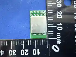
Module SDC-LE-02HD Specification
Document
V1.0
edition
revision content
date
Revision Author
V1.0
Initial Version
2026/5/18
WZJ
2 / 8
1. Product Overview
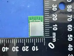
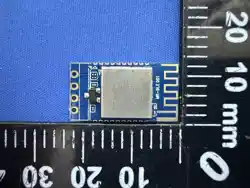
The SDC-LE-02HD is a dual-mode Bluetooth module featuring a plug-in interface, with
serial port compatibility for 3.3V voltage levels. Its key features include:
BT5.4 Dual Mode(PCaA15E2B On Board,QDID:215269)
16-bit stereo, software EQ equalizer, 1-stage DRC dynamic range compression
A 32-bit RISC-V CPU with a clock frequency of 125 MHz, featuring 4 MB of built-
in Flash memory and 128 KB of built-in RAM.
The radio frequency transmission power is 6 dBm, with a reception sensitivity of-
90.5 dBm at EDR (2 MHz bandwidth).
UART serial port, MUTE mute control
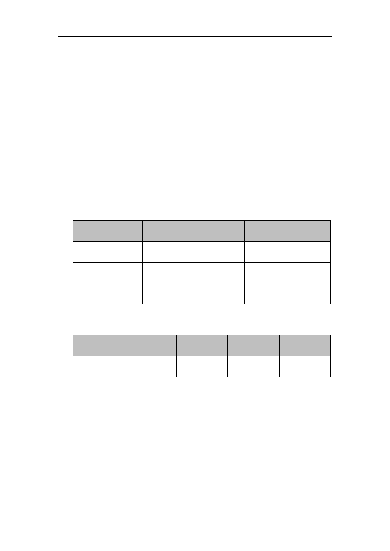
2. Electrical Parameters
electrical character
name
least value
representative
value
crest value
unit
I/O supply voltage
-
3.3
-
V
VDDIO
-
3.3
-
V
working temperature
-40
85
℃
Storage temperature
-65
150
℃
*Absolute maximum rated value; exceeding this may cause chip damage.
IO parameter
name
least value
representative
value
crest value
unit
VIL
-0.3
1.27
V
VIH
2.03
3.6
V
3 / 8
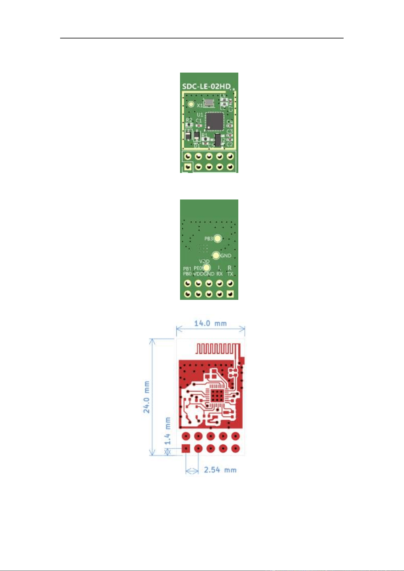
3. External dimensions
Front (TOP) appearance
Back (-bottom) appearance
Module Dimension Diagram

4 / 8
4. Pin Definition
The SDC-LE-02HD features a total of 10 interfaces.
pin
Signal
Name
description
Pin type
PB1
AUDIO
After audio connection, the
output is low-level with a
maximum voltage rating of
3.6 V.
O( output )
PE0
MUTE
Mute control pin: Muted at
low level
O( output )
AGND
AGND
Modularly
P( source )
DACL
M DACL
Left channel audio output
O( output )
DACR
M DACR
Right channel audio output
O( output )
PB0
APP
After connection, the app
outputs a low level with a
maximum voltage rating of
3.6 V.
O( output )
VDD
VDD
Positive terminal of the power
supply, operating voltage
range: 3.0V to 6V (typically
5V)
P( source )
GND
GND
Power supply location
P( source )
(RX)PE6
UART_RX
Serial RX data receiver,
compatible with 3.3V/5V
voltage levels
I( import )
(TX)PE7
UART_TX
Serial TX data transmitter,
compatible with 3.3V/5V
voltage levels
O( output )
Pin Function Definition Table
5 / 8
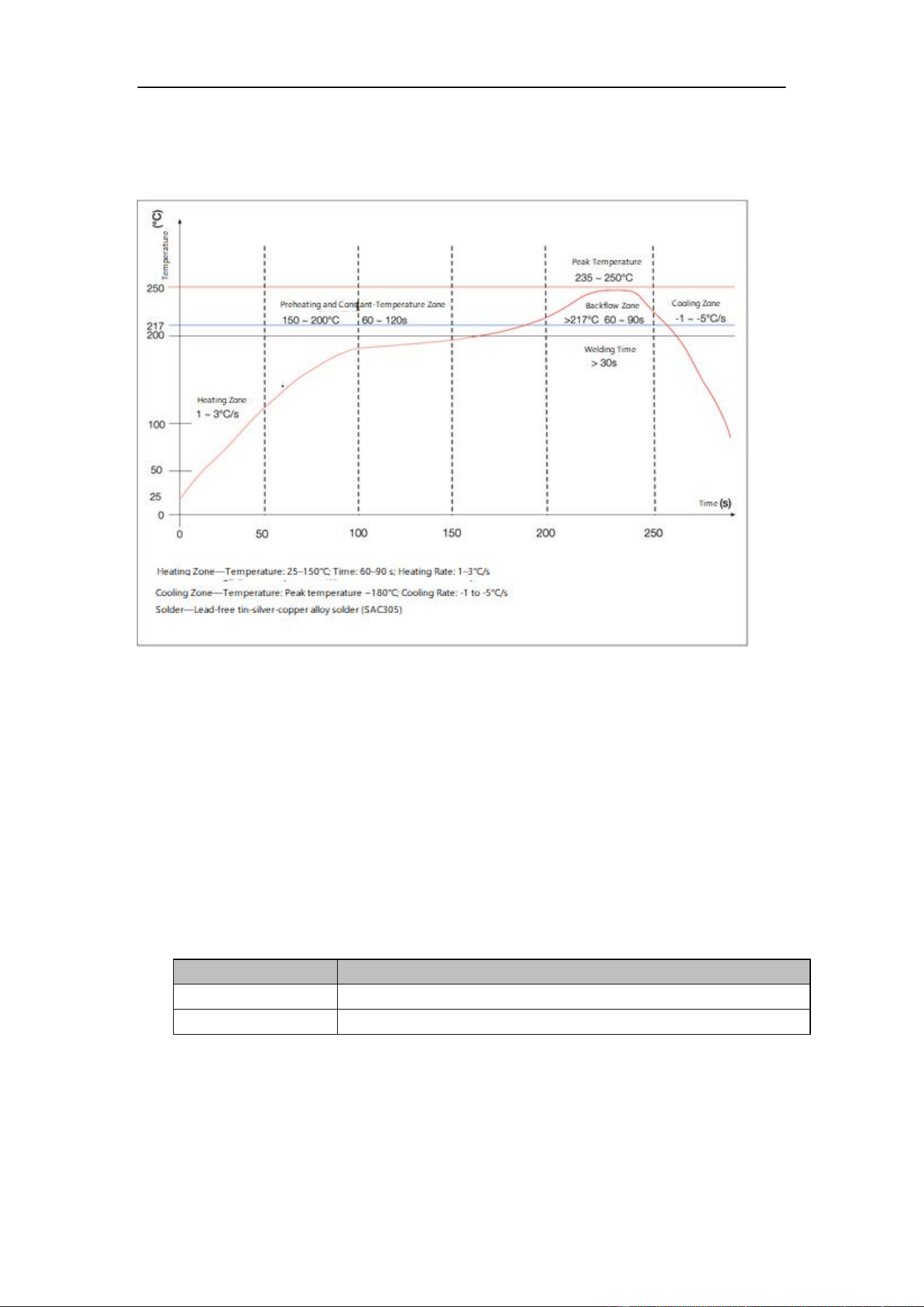
5. plant use
Furnace Temperature Curve
Reflow soldering temperature curve
It is recommended that the module undergo only one reflow soldering process.
ultrasonic vibration
Avoid exposing the module to vibrations from ultrasonic equipment such as ultrasonic welding
machines or ultrasonic cleaners. The vibrations from such equipment may resonate with the
internal crystal oscillator of the module, leading to oscillator failure or malfunction, which can
result in the module failing to operate or experiencing performance degradation.
For ultrasound application scenarios, please contact us to provide the specific model.
6. pack
Packaging Type
explain
Bandage pack
TBD
Disk packaging
TBD

6 / 8
FCC Statement
Any Changes or modifications not expressly approved by the party responsible for
compliance could void the user’s authority to operate the equipment.
This device complies with part 15 of the FCC Rules. Operation is subject to the following two
conditions:
(1) This device may not cause harmful interference, and
(2) This device must accept any interference received, including interference that may
cause undesired operation.
FCC Radiation Exposure Statement:
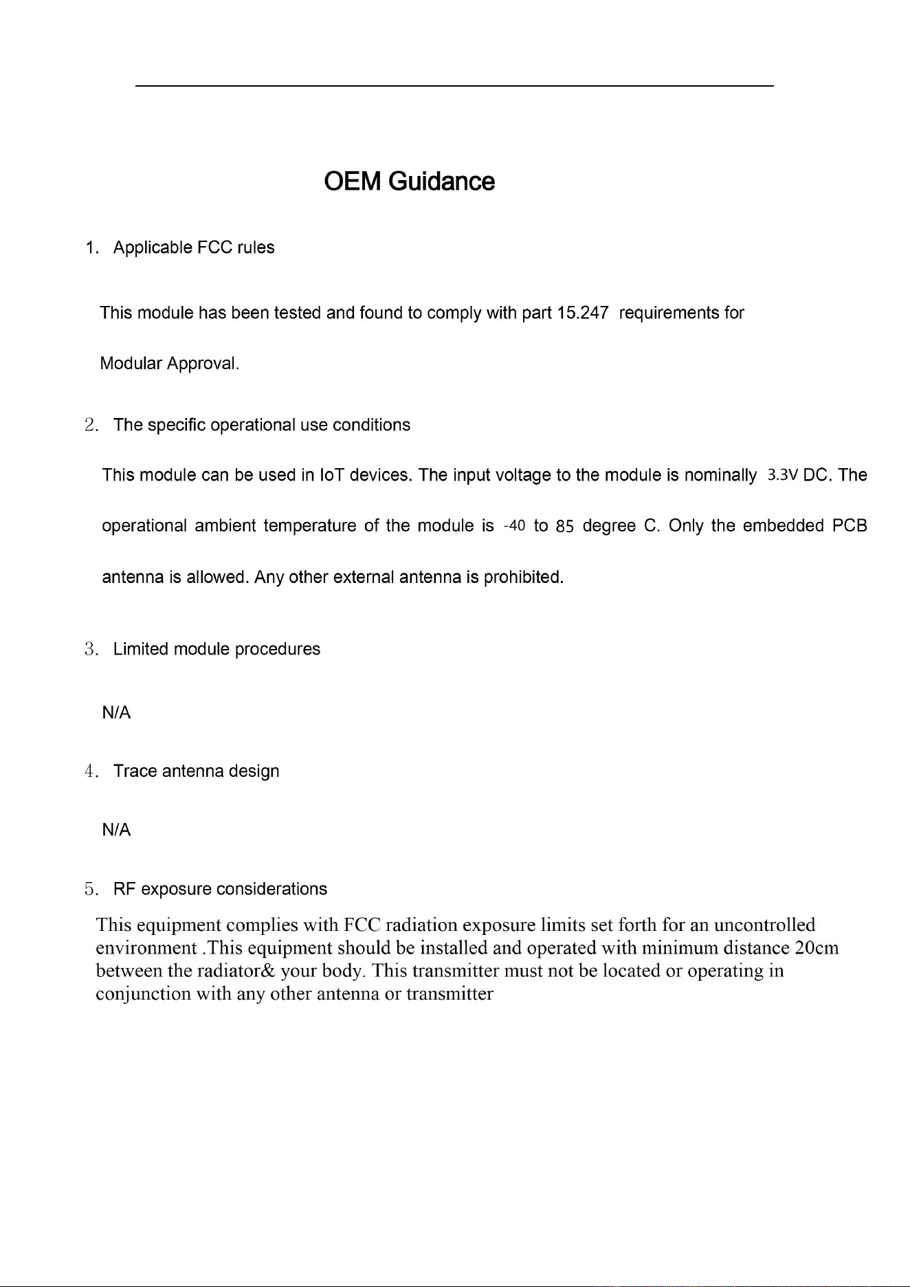
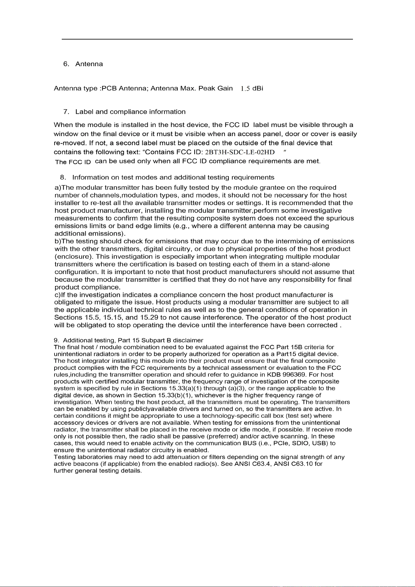
This equipment complies with FCC radiation exposure limits set forth for an uncontrolled
environment .This equipment should be installed and operated with minimum distance 20cm
between the radiator& your body. This transmitter must not be located or operating in
conjunction with any other antenna or transmitter.
Note : This equipment has been tested and found to comply with the limits for a Class B digital
device, pursuant to part 15 of the FCC Rules. These limits are designed to provide reasonable
protection against harmful interference in a residential installation. This equipment
generates,uses and can radiate radio frequency energy and, if not installed and used in
accordance with the instructions, may cause harmful interference to radio communications.
However, there is no guarantee that interference will not occur in a particular installation. If
this equipment does cause harmful interference to radio or television reception, which can be
determined by turning the equipment off and on, the user is encouraged to try to correct the
interference by one or more of the following measures:
—Reorient or relocate the receiving antenna.
—Increase the separation between the equipment and receiver.
—Connect the equipment into an outlet on a circuit different from that to which the receiver is
connected.
—Consult the dealer or an experienced radio/TV technician for help.
7 / 8
8 / 8