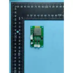
1. Circuit Composition:The circuit consists of Bluetooth, power amplifier, storage,
communication interface, speaker interface, and USB port. See the PCB layout
diagram for details.
2. Bluetooth Electrical Parameters:
蓝牙 Bluetooth
VoltageInput
2.2-4.5V
GPIOInputVoltage
-0.3-(VDDIO+0.3)V
Loadingcurrent
4.2V—150ma
AmbientTemperature
-40-85C
Storagetemperature
-65-150C
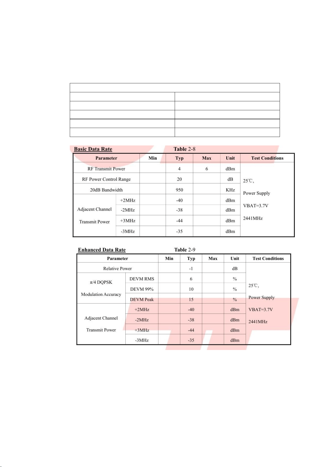
1. Bluetooth Transmit Characteristics (Basic Data Rate)
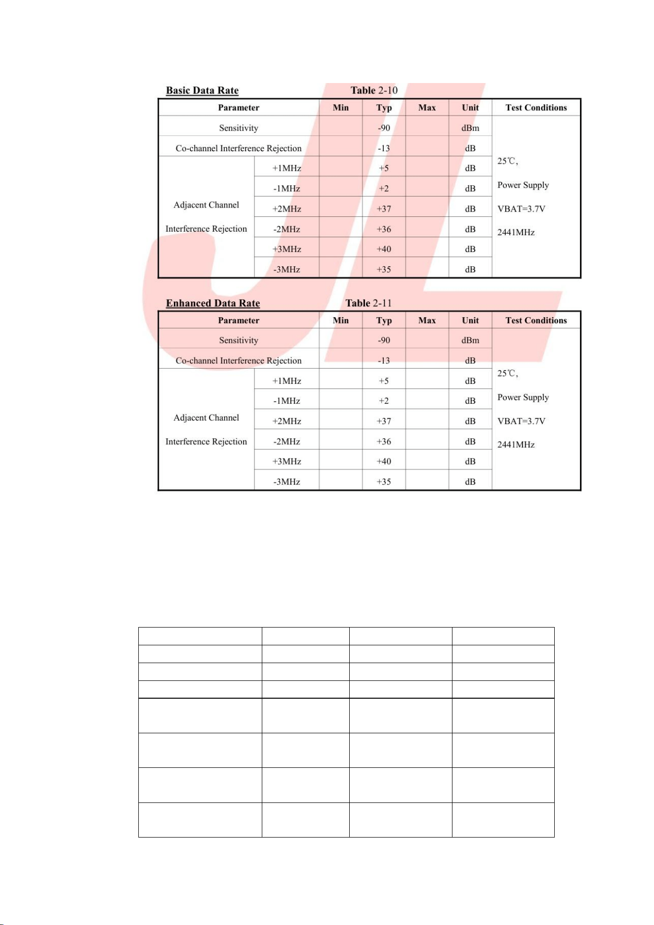
2. Bluetooth Receive Characteristics (Basic Data Rate)
3. Power Amplifier Section:
Parameter
Min
Max
Unit
Supply Voltage
2.8
5.5
V
Storage Temperature
-65
150
°C
Input Voltage
-0.3
VDD
V
ESDVoltage
Tolerance
4000
V
Junction
Temperature
150
°C
Operating
Temperature
-40
85
°C
Recommended
Operating Voltage
3.3
5.5
V
Thermal Resistance
θJC (eSOP8)
20
°C/W
Thermal Resistance
θJA (eSOP8)
80
°C/W
Soldering
Temperature
220
°C
Operating Conditions (unless otherwise specified): TA = 25 °C, VDD = 5 V
Symbol
Parameter
Test
Conditions
Min
typecal
Max
Unit
VDD
Supply Voltage
3.3
5.5
V
I0D
Quiescent
Supply Current
VDD=3.6V,
IN=0V, No
Load
12
ma
VDD=5.0V,
IN=0V, No
Load
18
ma
I5D
Shutdown
Leakage Current
Vctrl=VDD
1
20
uA
VOS
Output Offset
Voltage
10
40
mv
RO
Output
Resistance
3
K
PSRR
Power Supply
Rejection Ratio
217HZ
-80
dB
20KHZ
-72
dB
CMRR
Common Mode
Rejection Ratio
-70
dB
fSW
Modulation
Frequency
VDD=3.0V
to 5.25V
450
KHZ
η
Efficiency
Po=0.5W,
RL=4Ω,
VDD=3.6V
90
%
VIH
Logic Control
Input High
Voltage
1.4
1.4
V
VIL
Logic Control
Input Low
Voltage
0.4
V
THICTRL
One-Line Pulse
High Time
1
12
uS
TLOC TRL
One-Line Pulse
Low Time
1
12
uS
TOFF
CTRL Shutdown
Time
100
uS
Output
Power
(Class AB)
THD=1%,
f=1KHz, RL=2Ω
3.9
W
THD=1%,
f=1KHz, RL=4Ω
2.1
W
THD=10%,
f=1KHz, RL=2Ω
4.7
W
THD=10%,
f=1KHz, RL=4Ω
2.9
W
Output
Power
(Class D)
THD=1%,
f=1KHz, RL=2Ω
4
W
THD=1%,
f=1KHz, RL=4Ω
2.6
W
THD=10%,
f=1KHz, RL=2Ω
5
W
THD=10%,
f=1KHz, RL=4Ω
3.1
W
THD (Distortion)
f=1KHz,
Class D,
RL=2Ω/4Ω,
P0=0.5W
0.1%
SNR (Signal-to-
Noise Ratio)
RL=2Ω,
P0=0.5W
85
dB
4. Storage Section:
Supply Voltage
2.7-3.6V
Static Current Consumption
1uA
Storage Temperature
-40-85C
Capacity
16Mbyte
Data Retention Time
20 year
5. Communication Interface: BLE communicates with the motherboard
6. USB Interface: Program burning port
7. Speaker Interface:: Connects to 5W 8R speaker
8. Module Physical Dimensions: 60 x 37 mm. Supply Voltage: 5V. Maximum
Output Power: 5W x 2.

9. The module has passed relevant EMC and EMI certification tests

FCC Statement
This device complies with part 15 of the FCC Rules.Operation is subject to the following
two conditions:(1)This device may not cause harmful interference,and (2)this device must
accept any interference received,including interference that may cause undesired
operation.
Note:This equipment has been tested and found to comply with the limits for a Class B
digital device,pursuant to part 15 of the FCC Rules.These limits are designed to provide
reasonable protection against harmful interference in a residential installation.This
equipment generates, uses and can radiate radio frequency energy and,if not installed
and used in accordance with the instructions, may cause harmful interference to radio
communications. However, there is no guarantee that interference will not occur in a
particular installation. If this equipment does cause harmful interference to radio or
television reception,which can be determined by turning the equipment off and on,the
user is encouraged to try to correct the interference by one or more of the following
measures:
—Reorient or relocate the receiving antenna.
—Increase the separation between the equipment and receiver.
—Connect the equipment into an outlet on a circuit different from that to which the
receiver is connected.
—Consult the dealer or an experienced radio/TV technician for help.
Note:The Grantee is not responsible for any changes or modifications not expressly
approved by the party responsible for compliance. such modifications could void the
user's authority to operate the equipment.
The device has been evaluated to meet general RF exposure requirement.
To maintain compliance with FCC's RF exposure guidelines,the distance must be at least
20 cm between the radiator and your body, and fully supported by the operating and
installation configurations of the transmitter and its antenna(s).

I
ntegration instructions for host product manufacturers according to KDB 996369
D03OEM Manual v01
2.2 List ofapplicable FCC rules
FCC Part 15 Subpart C 15.247
2.3 Specific operational use conditions
The module can be used for mobile applications with a maximum 1.68dBi antenna. The
host manufacturer installing this module into their product must ensure that the final
composite product complies with the FCC requirements by a technical assessment or
evaluation to the FCC rules, including the transmitter operation. The host manufacturer
has to be aware not to provide information to the end user regarding how to install or
remove this RF module in the user's manual of the end product which integrates this
module. The end user manual shall include all required regulatory information/warning as
show in this manual
2.4 Limited module procedures
The device is a Single module and complies with the requirement of FCC Part 15.212
2.5 Trace antenna designs
Not applicable, The module has its own antenna, and does n t need a host sprinted board
micro strip trace antenna etc
2.6 RF exposure considerations
The device has been evaluated to meet general RF exposure requirement. The device
can be used in portable exposure condition without restriction, and if RF exposure
statement or module layout is changed, then the host product manufacturer required to
take responsibility of the module through a change in FCC ID or new application The
FCC ID ofthe module cannot be used on the final product In these circumstances, the
host manufacturer will be responsible for re-evaluating the end product (including the
transmitter) and obtaining a separate FCC authorization
2.7 Antennas
Antenna Specification are as follows.
Lype of antenna: PCB Antenna
Gain of antenna: 2.4GHz@ 1.68dBi Max.
This device is intended only for host manufacturers under the following conditions: The
transmitter module may not be co-located with any other transmitter or antenna, The
module shall be only used with the internal antenna(s) that has been originally tested and
certified with this module. The antenna must be either permanently attached or employ a
"unique" antenna coupler As long as the conditions above are met, further transmitter
test will not be required However, the host manufacturer is still responsible for testing
their end-product for any additional compliance requirements required with this module
installed (for example, digital device emissions, PC peripheral requirements, etc)

2.8 Label and compliance information
Host product manufacturers need to provide a physical or e-label stating " Contains FCC
ID:2BX5S-BEF4BLE1 "with their finished product
2.9 Information on test modes and additional testing requirements
Host manufacturer must perform test of radiated & conducted emission and spurious
emission, e.t.c according to the actual test modes for a stand-alone modular transmitter
in a host, as well as for multiple simultaneously transmitting modules or other transmitters
in a host product.
Only when all the test results oftest modes comply with FCC requirements, then the
endproduct can be sold legally.
2.10 Additional testing, Part 15 Subpart B disclaimer
The modular transmitter is only FCC authorized for FCC Part 15 Subpart C 15.247 and
that the host product manufacturer is responsible for compliance to any other FCC rules
that apply to the host not covered by the modular transmitter grant of certification.If the
grantee markets their product as being Part 15 Subpart B compliant (when it also
contains unintentional-radiator digital circuit), then the grantee shall provide a notice
stating that the final host product still requires Part 15 Subpart B compliance testing with
the modular transmitter installed