-3--1-
Technical Specifications
· Voltage: 3.7 V
· Capacity: 200 mAh
· Charging Power: 5 V 0.05 A (0.25 W)
· Frequency: 433.925 MHz
· Ambient Operating Temperature: −5°C to 50°C
· Transmission Range:
Outdoor: up to 220 feet
Indoor (through two walls): up to 115 feet
Function Description
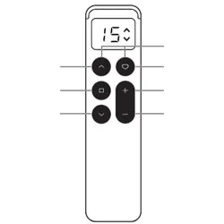
The WR09-15CH is a 15-channel transmitter. The number
displayed on the screen indicates the currently selected
control channel.
Press CH− (decrease) or CH+ (increase) to change the
channel.
When the selected channel number appears on the
display, the channel is active and ready for control.
When “0” is displayed on the screen, all channels are
active, indicating Group Control Mode.
Tips:
Do not expose the remote to moisture or impact, as this
may affect its service life.
If the transmission range is significantly reduced or
responsiveness decreases during use, please recharge the
remote promptly.
Warnings:
The remote is not user-serviceable. Do not disassemble it,
as this may cause damage or pose a risk of explosion.
* If the remote malfunctions, press Reset with the included pin.
Release. The screen lights up, then shows channel '1' after 2
seconds to confirm the reset.
Do not dispose of electrical products with household
waste.
Please recycle damaged electrical products properly.
INS-101-C124
-2-
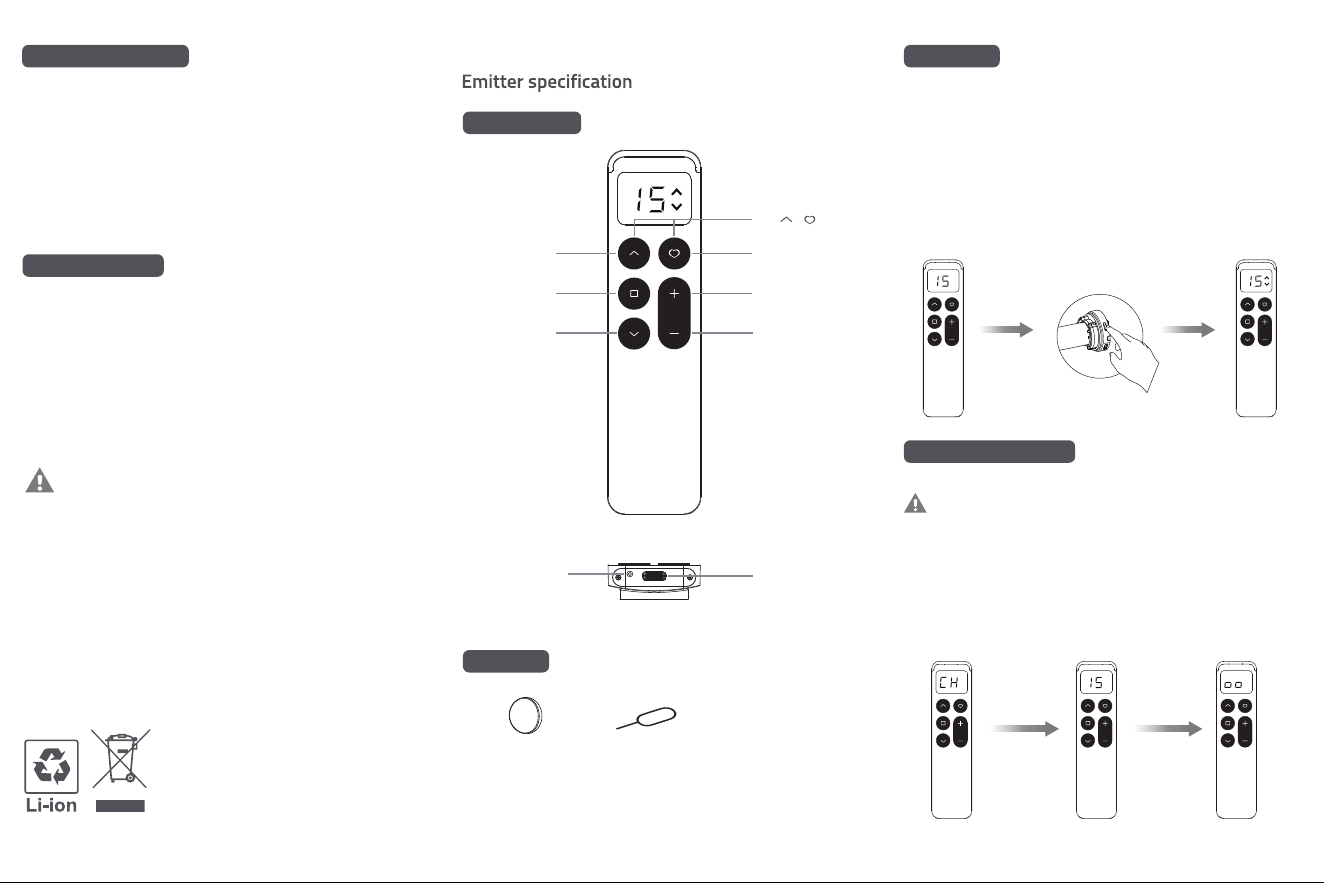
Button Functions
Accessories
Pairing Steps
WR09-15CH
① Press the CH− or CH+ button to select the channel(1–15) to
pair.
Select
Channel
② Press and hold the programming button on the motor head
for about 2 seconds until the motor jogs once.
③ Within 10 seconds, press and hold the STO P button for 2
seconds. The motor will jog twice, indicating that pairing is
successful.
2 secs
Hiding Remote Channels
In the setting mode, pressing the UP or DOWN button will
quickly exit. To change the active channel, the remote must
be reset to select a new channel.
A-01 January 2026
UP
FRONT
BOTTOM
STOP
DOWN
50%
P( + )
CHANNEL
UP
CHANNEL
DOWN
① Press and hold CH+ and CH−. The screen will display “CH”,
then “15” .
② Press CH+ or CH− to select the desired channel (Channel 1 to
Channel 15).
③ After selecting the channel, press and hold STOP. When the
screen displays oo, the setting is successfully saved.
Reset
button
Magnetic Holder Ejector Pin
Charging
port
—
---
* Channel 0 is for Group Control Mode, which controls all chan-
nels simultaneously but cannot be paired individually.
-4- -6--5-
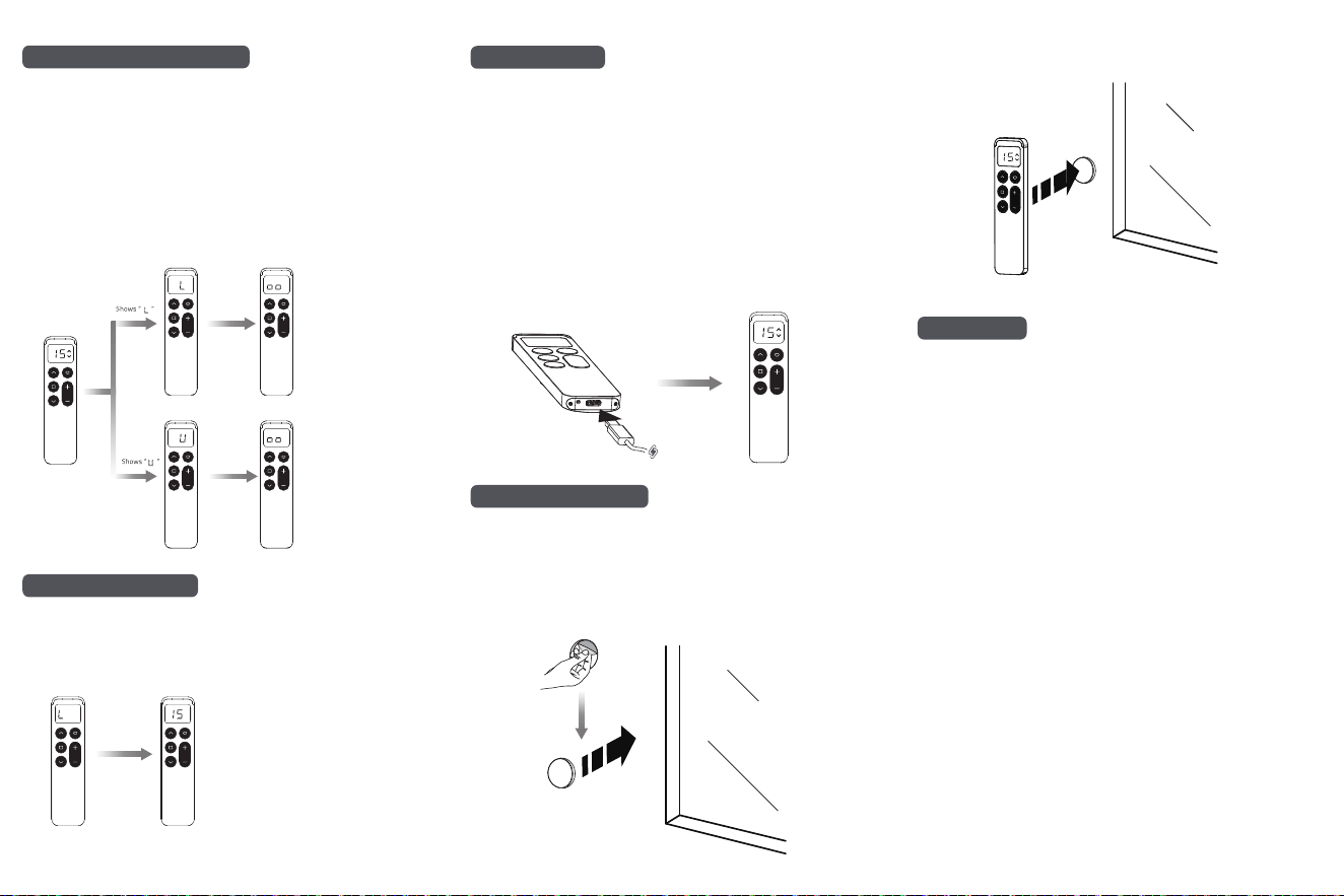
Low Battery Notifications
Metal Bracket Installation
When the battery is low, the remote displays “L” for about 3
seconds on wake-up, indicating that it needs to be recharged.
Normal operation is unaffected during the “L” display, which
clears automatically after 3 seconds.
Combination Button Lock/Unlock
Switch to
Combination
Button Lock
state
Switch to
Combination
Button Unlock
state
The remote is unlocked by default and can be switched
between Lock and Unlock modes.
When Locked, combination buttons are disabled, no
display appears, and no codes are transmitted.
When unlocked, the combination buttons display an icon
indicator.
Locking only affects combination buttons and does not
impact the operation of other buttons.
Note: The SETTING (P) button is located on the top left of
the remote.
Press and hold
STOP(>15 s)
Press and
hold SETTING
(P) (>1 s)
Press and
hold SETTING
(P) (>1 s)
Charging Indicator
When the charger is connected, the remote will automatically
wake up and display the channel number. The low battery alert
will no longer appear.
During charging, the UP & DOWN icons on the display screen
will flash, and the remote will not enter low-power mode.
When the battery is fully charged, the UP & DOWN icons will
remain steadily lit.
Pressing any button during charging temporarily returns the
remote to the normal display. If no operation occurs for 10
seconds, it will revert to the charging display.
If the charger is connected when the battery is already full, the
UP & DOWN icons will flash for approximately 1 minute before
remaining steadily lit.
UP & DOWN icons
stay lit when fully
charged.
Note: Install the bracket only on a solid, dry wall surface where
the adhesive can bond securely. Do not use it on damp walls or
in high-humidity environments, as poor adhesion may cause the
bracket to fall off.
Peel off the adhesive backing and attach the bracket to the wall
with the concave side facing vertically.
Align the remote with the bracket, and it will attach magnetically.
Any changes or modifications not expressly approved by the party
responsible for compliance could void the user’ s authority to
operate the equipment.
This device complies with Part 15 of the FCC Rules.
Operation is subject to the following two conditions:
(1) This device may not cause harmful interference, and
(2) This device must accept any interference received, including
interference that may cause undesired operation.
Note: This equipment has been tested and found to comply with
the limits for a Class B digital device, pursuant to Part 15 of the FCC
Rules. These limits are designed to provide reasonable protection
against harmful interference in a residential installation. This
equipment generates, uses and can radiate radio frequency energy
and, if not installed and used in accordance with the instructions,
may cause harmful interference to radio communications. However,
there is no guarantee that interference will not occur in a particular
installation. If this equipment does cause harmful interference to
radio or television reception, which can be determined by turning
the equipment off and on, the user is encouraged to try to correct
the interference by one or more of the following measures:
— Reorient or relocate the receiving antenna.
— Increase the separation between the equipment and receiver.
— Connect the equipment into an outlet on a circuit different from
that to which the receiver is connected.
— Consult the dealer or an experienced radio/TV technician for help.
FCC Radiation Exposure Statement:
This equipment complies with FCC radiation exposure limits set
forth for an uncontrolled environment.
FCC Statement