MAINTENANCE
Proper cleaning of the unit is required. When rubbing or scouring, always move gently in the direction of the polish lines(grains).
A Scotch-Brite™ general purpose pad may be used. DO NOT USE STEEL WOOL.
MAINTENANCE FOR LAMINATES
Laminate surfaces may be cleaned with warm water and mild soaps. Non-abrasive cleaners may also be used. Cleaning products
containing bleaching agents should not be used. Large quantities of these agents or extended periods of time of exposure to them can
cause discoloration.
CAUTION:
1. This equipment is designed and sold for commercial use only by personnel trained and experienced in its operation and is not sold
for consumer use in and around the home nor for use directly by the general public in food service locations.
2. Do not immerse unit in water.
3. All repairs should be done by an authorized service center.
4. Unit should be turned off when not in use. It is recommended that unit be disconnected from power supply by removing plug from
receptacle or shutting off power disconnect supply to the unit.
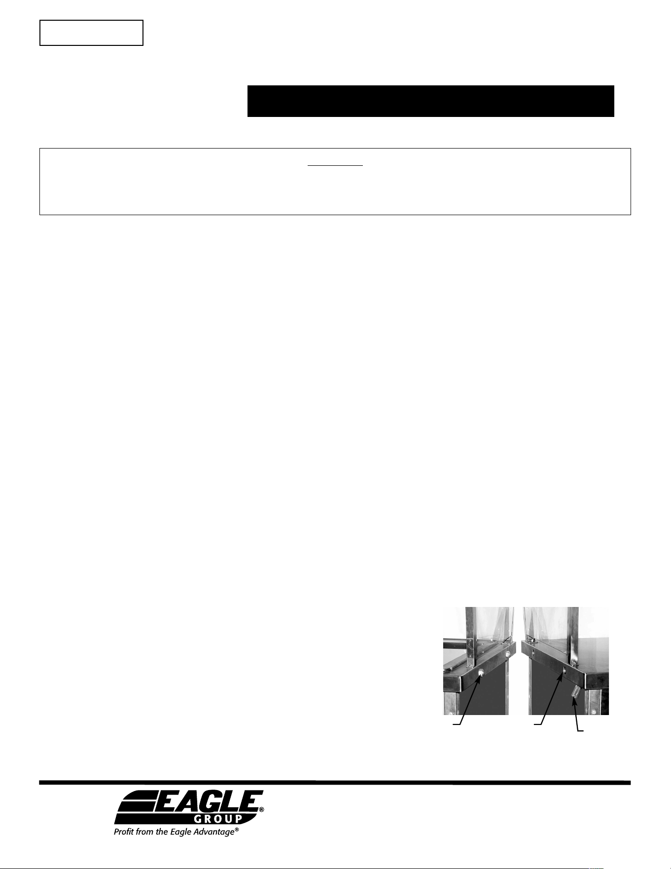
DOCKING DEVICE
The device comprises of two sub-assemblies: a male bullet catch and a female receiver with a locking plate.
1. Align the units so that the bullet catch and receivers line up.
2. Pull the lever and push the two units together so that the bullet catch
is pushed all the way into the receiver.
3. Release the lever and the two units are now securely docked together.
4. To release the two units, pull the lever and slowly push the two units
apart. Release the lever and now your units are separate.
OPERATIONS MANUAL & INSTRUCTIONS
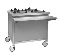
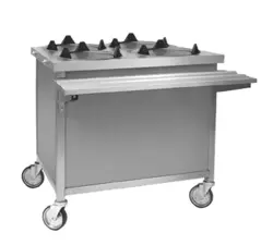
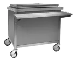
Director’s Choice
®
Tray & Silverware Unit and
Rack/Tray Dispensers
EG10082 Revised 10/23
bullet catch receiver
lever
Retain this manual
for future reference.
INSTRUCTION SHEET
#366758
Eagle Foodservice Equipment, Eagle MHC, and SpecFAB
®
are divisions of Eagle Group. ©2023 by the Eagle Group
• 100 Industrial Boulevard, Clayton, Delaware 19938-8903 U.S.A.
• Phone: 302/653-3000 • 800/441-8440 • Fax: 302/653-2065
• www.eaglegrp.com • www.eaglegrpnews.com • www.eaglemhc.com
CAUTION
INSPECT CONTENTS IMMEDIATELY AND FILE CLAIM WITH DELIVERING
CARRIER FOR ANY DAMAGE. SAVE YOUR BOX AND ALL PACKING MATERIALS.
YOU ARE RESPONSIBLE FOR DAMAGE TO YOUR UNIT IF RETURNED IMPROPERLY PACKED.
CABLE REPLACEMENT INSTRUCTIONS
2
Director’s Choice
®
Tray & Silverware Unit
and Rack/Tray Dispensers
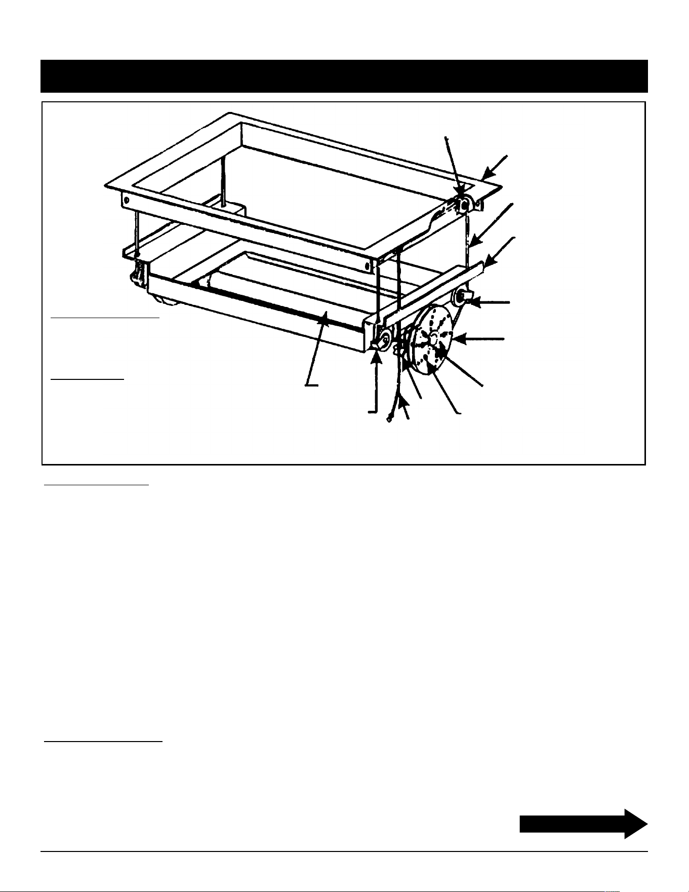
Power
Shaft
Screw “B”
Screw “A”
Carrier Pulley
Retainer
Carrier
Pulley
Carrier
Weldment
Flange
Weldment
Tape Lock Washer
(Cable Clamp)
Cable
Limit
Cable
Shaft
Clamp
Power
Drum
Materials Furnished
2 - (Two) Replacement Cables
2 - (Two) Power Drum Keys
Tools Needed
Needle Nose Pliers
Hammer
1/4˝ Punch (Screwdriver will do)
Phillips Head No. 3 Screwdriver
Box End or Hex Socket Wrenches
Removal of Cables
1) Turn unit upside down on flat surface.
2) With a box end or hex socket wrench, loosen the two hex head bolts to relax strap clamps holding power shaft.
The power shaft will turn about one revolution when free of clamps. Keep one hand on power shaft while
loosening the clamps so it will not spin suddenly and cause to "spill" off from power drums.
3) With the aid of another person, unwind the cables from the power drums by pulling the cables up evenly (allowing
the power shaft to turn) until the cables are completely off drums. Do not allow the cables to "spill" off the power
drums, as this puts an undesirable twist in the cables.
4) With a Phillips head screwdriver, remove screw A and screw B from power drum and put in a safe place. Do on
other side.
5) With a box end or hex socket wrench, loosen (do not take apart) the carrier pulleys and tape lock washers on
each side.
6) With needle nose pliers, pull out the ends of the cable, found in the center of the power drum, about 6" towards
you. In back of the two cable ends, find the power drum key. With the needle nose pliers, work the key up and
out. Remove the cable through the hole the key came out of. Remove the cable from the carrier pulleys and tape
lock washers; discard cable. Repeat on the other side.
Installing New Cables
1) Center 11ft. cable between two bottom lock washers. Thread through lock washers and through the guides
just above. Bring cable towards the center of the unit, threading between carrier pulley and carrier cable
retainer. Tighten hex lock nut on carrier pulley as the retainer is up against the metal flange as far as it can go.
Repeat on other side.
(continued on next page)

3
2) Position power shaft with the hole straight up and with the arrow pointing in the direction of the limit cable. Align
hole on the power drum with hole on the power shaft, showing heads of screws towards you.
3) Place ends of the cable in the hole and pull on the ends with a pair of needle nose pliers, bringing the ends out
about 6". Do not twist cables; make sure right cable is on the right side and the cable is on the left side.
4) Take the power drum key and place in the hole in back of the cables. With a 1/4" punch (screwdriver will do)
and a hammer, drive the key down into place making sure it has entered through both holes.
5) Pull cables up as far as they will go, and replace screw A in between the right and left cables. Pull cables in
direction of arrow and replace screw B over cables.
6) Repeat steps 2 through 5 on the other side.
7) Hold the cables up, to hold them taut. There will be two loops on each side-use your thumb and index finger to
support loops on each side.
8) Have another person wind up power shaft in direction of arrow stamped on power shaft, until all of cable is
wound back into power drums.
9) Once the cable is wound tight, continue to turn power shaft an additional 3/4 to one turn (for head load required
to support the weight of mechanism), and tighten the clamp bolt to prevent tube from turning.
10) Align groove on tape lock washers with cable. Tighten down tape lock washer to prevent slippage of cable in
future use.
11) Place unit back in counter and depress the platform fully several times to allow cables to attain their natural
position on power drums.
12) If platform is level, cable replacement is complete. If platform is uneven, loosen four tape lock washers and
allow cables to shift into a balanced tension. To help attain the condition, grip both power drums and apply
torque in direction of rotation that will put additional tension on cables. Tighten four tape lock washers and
re-install unit in counter.
Adjusting the Unit
1) Turn unit upside down on a flat surface.
2) With a socket or box end wrench, loosen two hex head bolts to relax strap clamps holding power shaft. Power
shaft will turn about one revolution when free of clamps, keep one hand on power shaft while loosening the
clamps so it will not spin suddenly and cause cable to "spill" off from power drums.
3) With the aid of another person, unwind cables from the power drums by pulling cables up evenly (allowing the
power shaft to turn) until cables are completely off drums. Do not allow cables to "spill" off the power drums, as
this puts an undesirable twist in the cables.
4) Remove eight screws from each power drum. If load rate is to be increased, re-install screws into a smaller
circle of holes. If load is to be decreased, re-install screws into larger circle of holes. Be certain that same circle
of holes is used on both power drums. Be certain that the cable emerges between the same relative screw
locations on both power drums.
5) Loosen cable clamp hex nuts at four corners under flange.
6) Hold cables up to hold them taut. There will be two loops on each side-use your thumb and index finger to
support the loops on each side.
7) Have another person wind up torque tube in direction of arrow stamped on power shaft, until all of the cable is
wound back into the power drums.
8) Once cable is wound tight, continue to turn power shaft an additional 3/4 to one turn (for head load required to
support weight of mechanism), and tighten the clamp bolts to prevent tube from turning.
9) Tighten-the cable clamp hex nuts at the four corners under the flange.
10) Place the unit back in the counter and depress the platform fully several times to allow cables to attain their
natural position on power drums.
Installing New Cables
(continued)
CABLE REPLACEMENT INSTRUCTIONS
(continued)
Director’s Choice
®
Tray & Silverware Unit
and Rack/Tray Dispensers
(
End
)
Cable replacement is complete.
ASSEMBLY INSTRUCTIONS
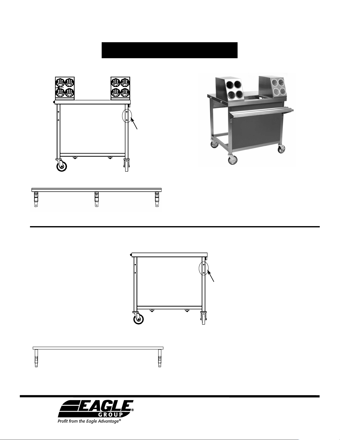
Work Shelves
1. Remove screws from the front of the unit.
2. Hold tray slide up to unit and align the
holes with the predrilled screw holes in
the unit.
3. Tighten screws and make sure tray slide
is securely mounted on unit.
1. Remove screws from the front of the unit.
2. Hold work shelf up to unit and align the
holes with the predrilled screw holes in
the unit.
3. Tighten screws and make sure work shelf
is securely mounted on unit.
location of
screws
location of
screws
Tray Slides
Director’s Choice
®
Tray & Silverware Unit and
Rack/Tray Dispensers
tray & silverware unit
shown with tray slide
Eagle Foodservice Equipment, Eagle MHC, and SpecFAB
®
are divisions of Eagle Group. ©2023 by the Eagle Group
• 100 Industrial Boulevard, Clayton, Delaware 19938-8903 U.S.A.
• Phone: 302/653-3000 • 800/441-8440 • Fax: 302/653-2065
• www.eaglegrp.com • www.eaglegrpnews.com • www.eaglemhc.com