
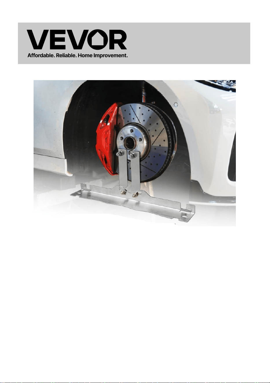
WHEEL ALIGNMENT & BALANCING TOOLS
MODEL:YL-716

- 1 -
MODEL:YL-716
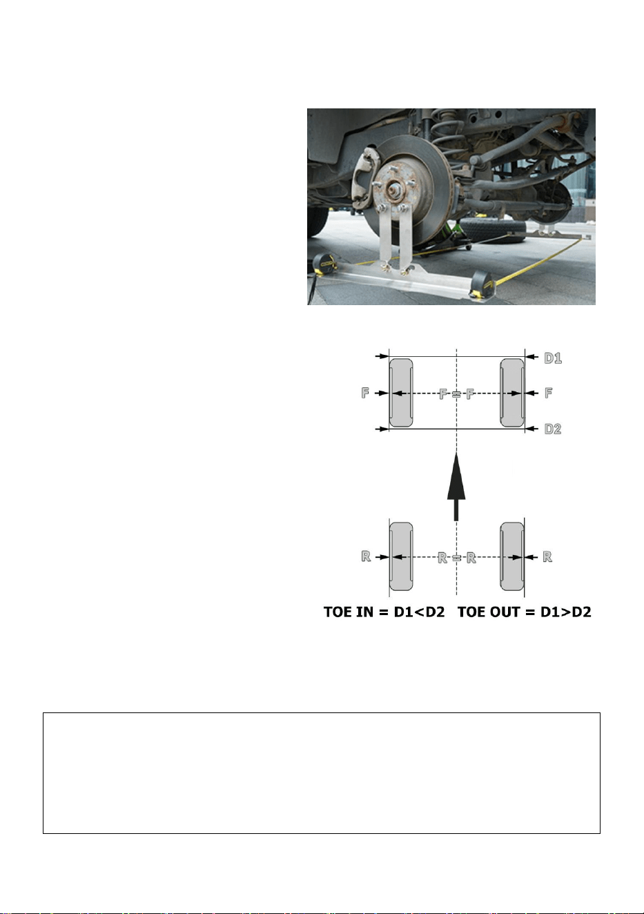
<Picture Only For Reference >
This is the original instruction, please read all manual instructions carefully
before operating. VEVOR reserves a clear interpretation of our user
manual. The appearance of the product shall be subject to the product you
received. Please forgive us that we won't inform you again if there are any
technology or software updates on our product.
WHEEL ALIGNMENT &
BALANCING TOOLS

- 2 -
IMPORTANT SAFEGUARDS
WARNING: Read and understand this entire manual before
operating or servicing this product. Failure to follow these
warnings and instructions can cause personal injury or
damage to valuable property.
1. Assemble only according to these instructions. Improper assembly can
create hazards.
2. Wear ANSI-approved safety goggles and heavy-duty work gloves
during assembly.
3. Keep assembly area clean and well-lit.
4. Keep bystanders out of the area during assembly.
5. Do not assemble when tired or when under the influence of alcohol,
drugs or medication.
6. Product capabilities apply to properly and completely assembled
product only.
7. Avoid children using the wheel alignment system. And this product is not
a toy. Do not allow children to play.
8. For additional information regarding the parts listed in the following
pages, please refer to the Assembly Diagram of this manual. Unwrap and
separate all parts in a clean work area. Please keep small spare parts out
of children's reach.
SAVE THESE INSTRUCTIONS
- 3 -
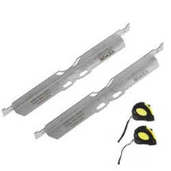
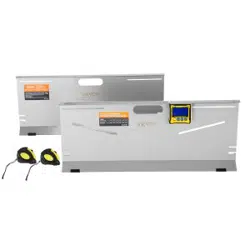
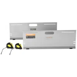
PACKAGE LIST
No.
Name
Description
Pic
QTY
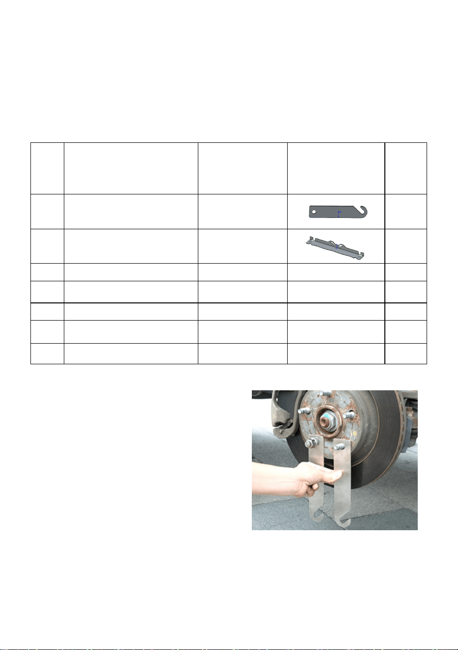
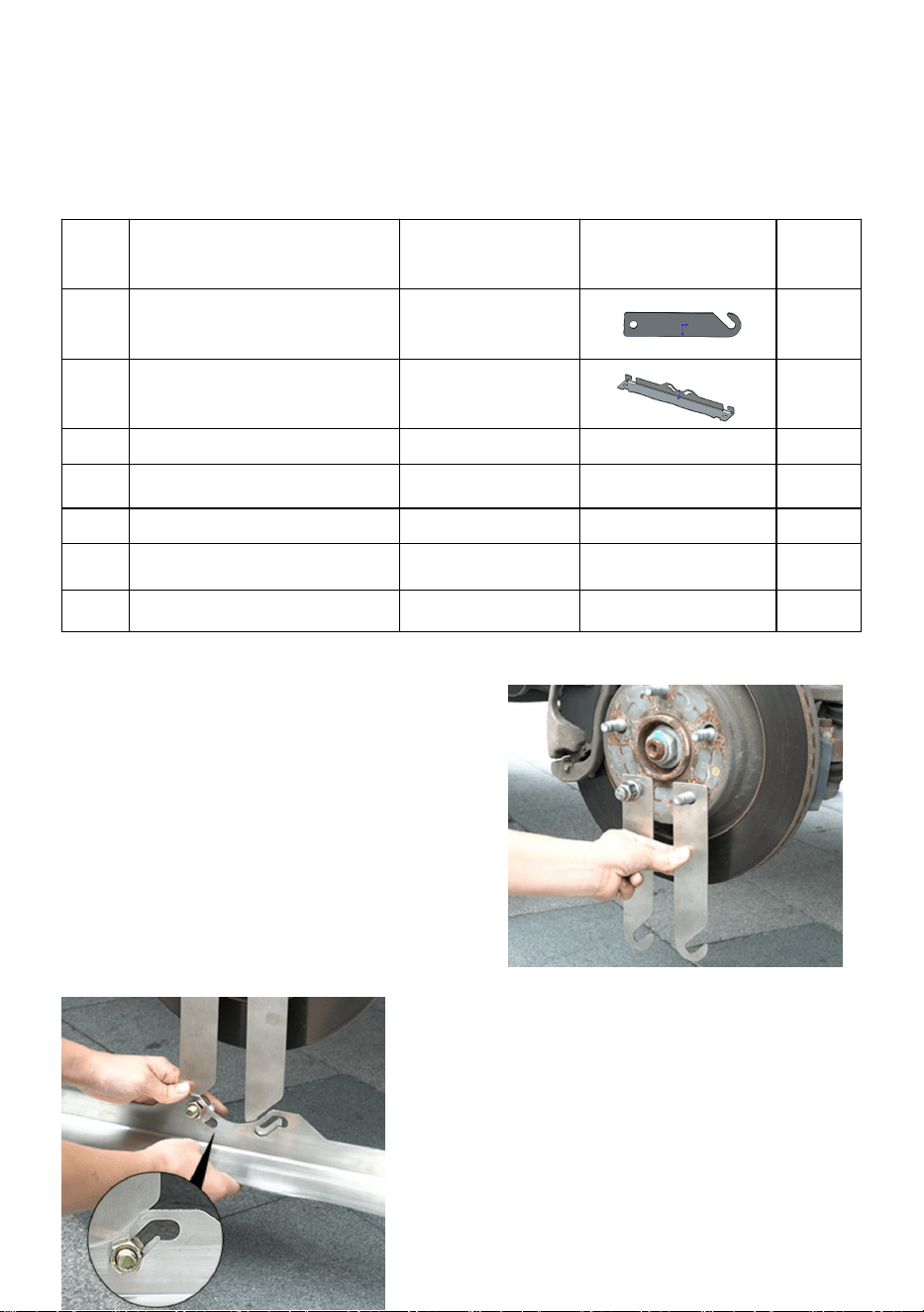
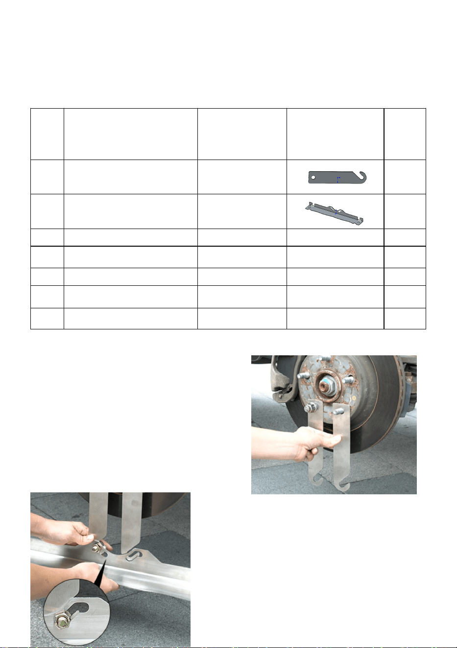
1
Extended plate
/
4
2
Reference plate
L=610mm
2
3
Hexagonal Bolt
M12*30
/
4
4
Nut
M12
/
4
5
Gaskets
12
/
4
6
Tape measure
3m(10ft)
/
2
7
Manual
/
/
1
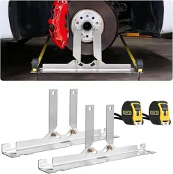
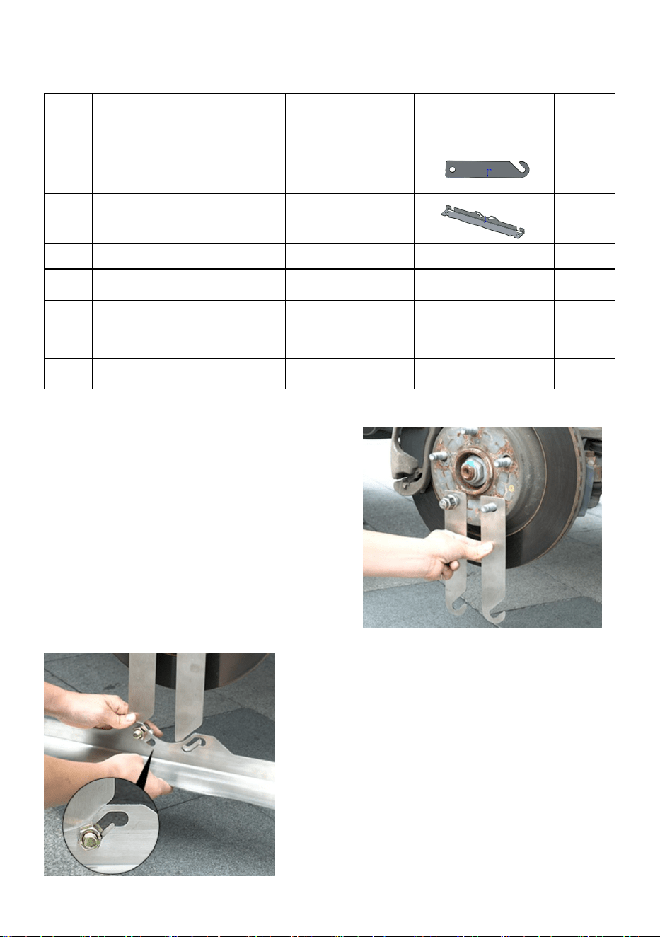
Installation steps
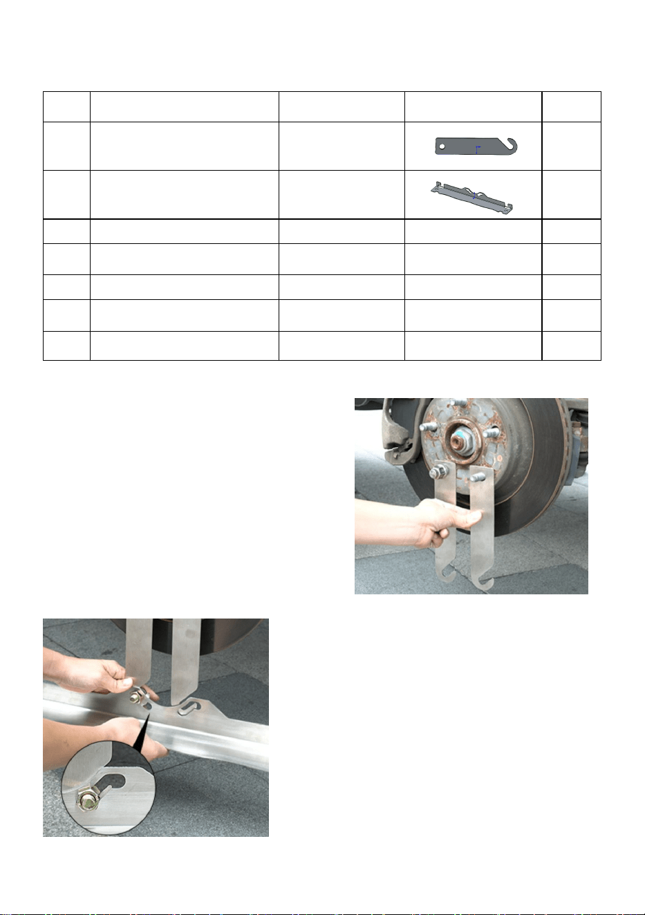
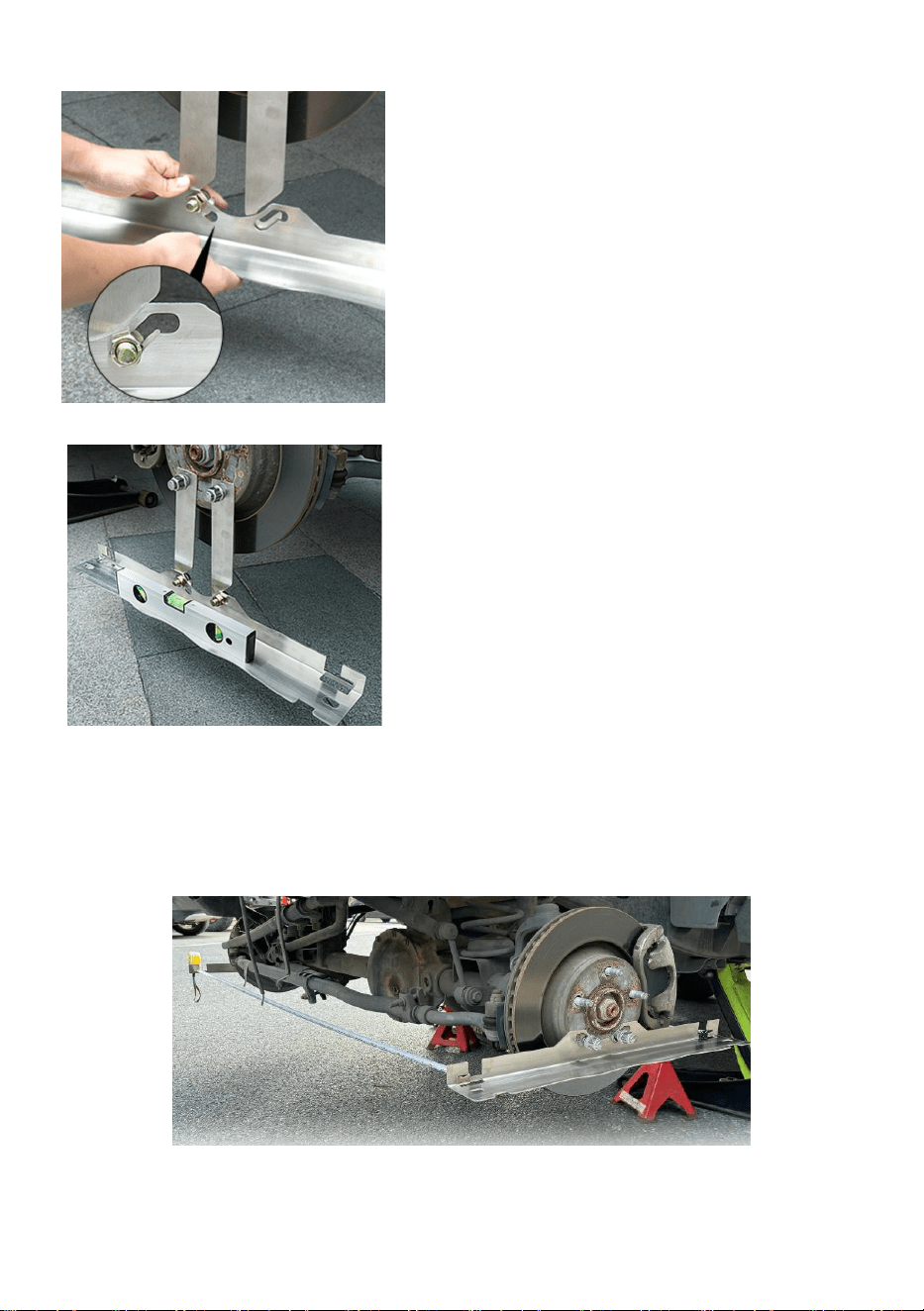
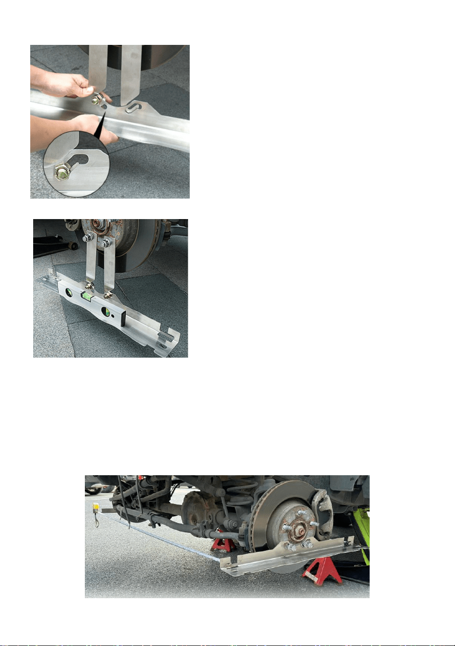
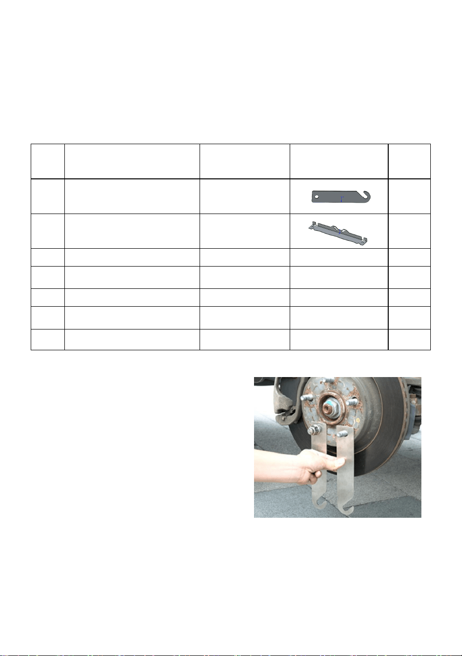
Step1.Install the Extended plate,
aligning the included recessed
connectors with the wheel stud
locations, ensuring they are securely
fastened to the studs while keeping the
installation smooth and stable.
Step2.Attach the Wheel Alignment Tool
Panel to the secured notch connector and
secure the alignment panel in place using
the nut with the notch connector parallel to
the ground.
- 4 -
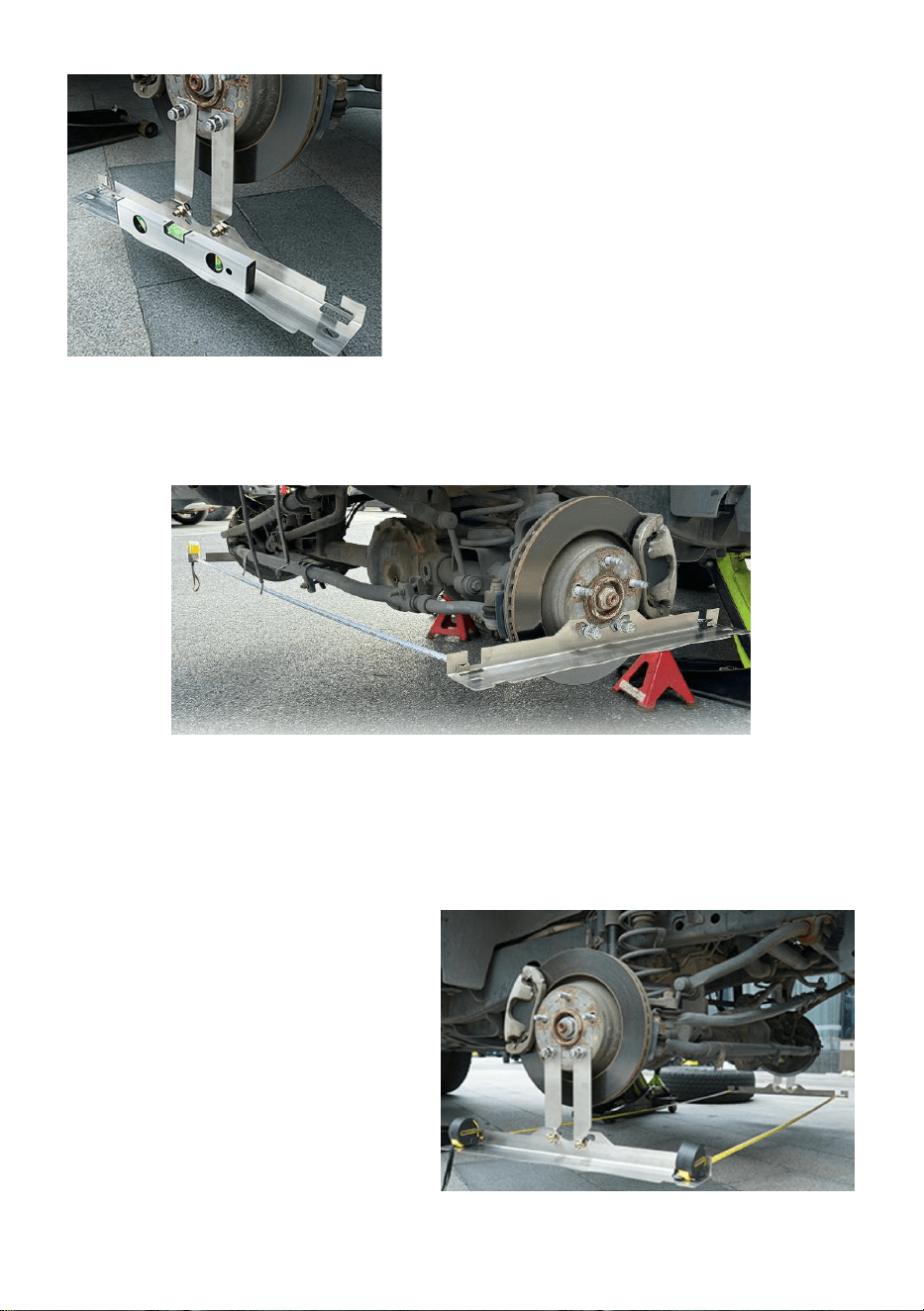
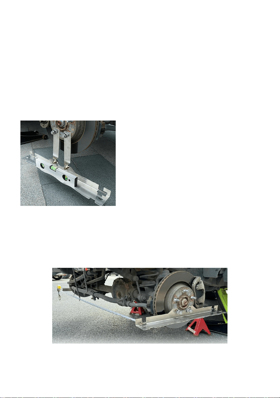
Step3.Use a level (not included) to adjust
the reference plate to a horizontal position
front to back, so that the value of the
measurement is more accurate.and then
tighten the screws. (make sure the screws
near the front of the vehicle are secured at
the lowest point of the panel holes)
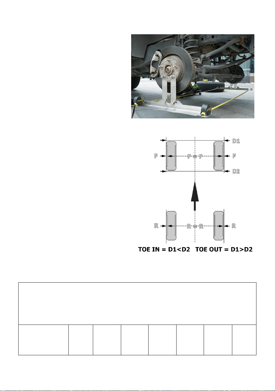
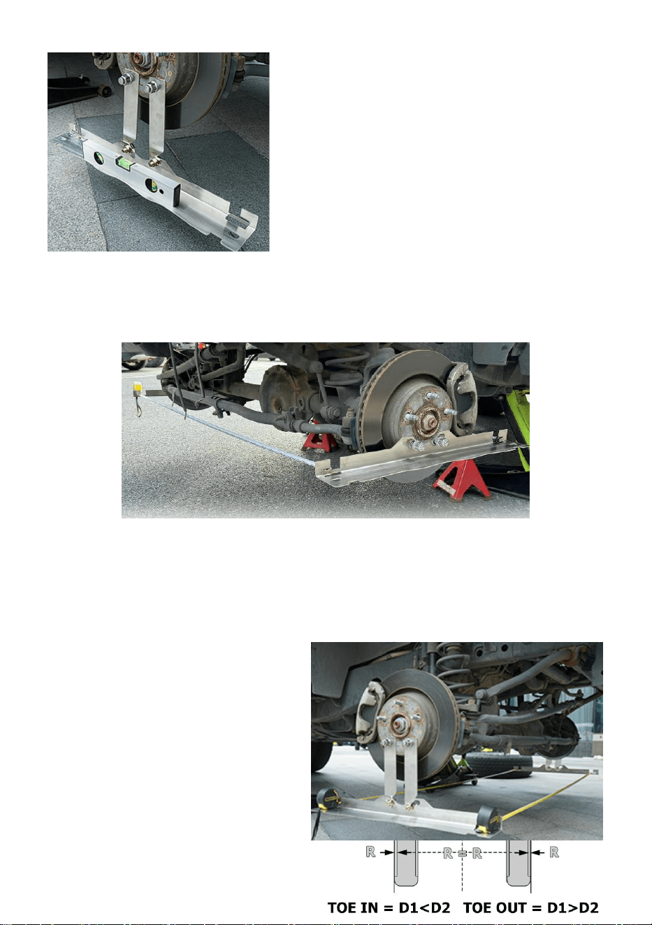
Step4.Repeat the same steps on opposite sides of the tyre.
If the chassis of your vehicle is high enough, you can also directly
install the reference plate onto the hub bearing without using an
extension plate.
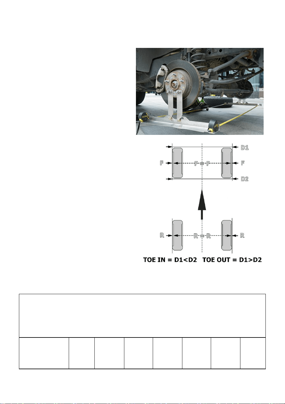
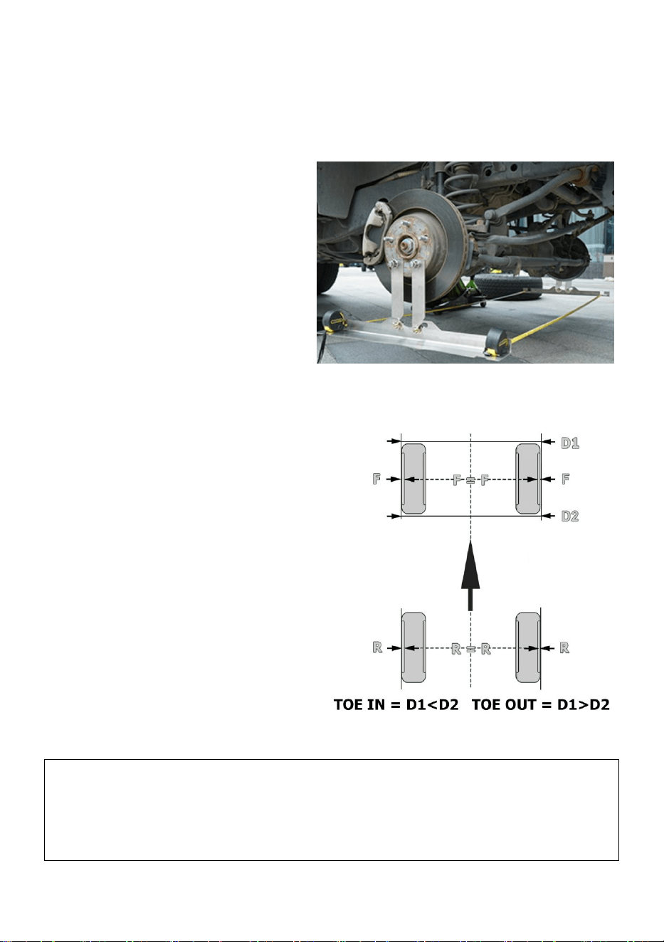
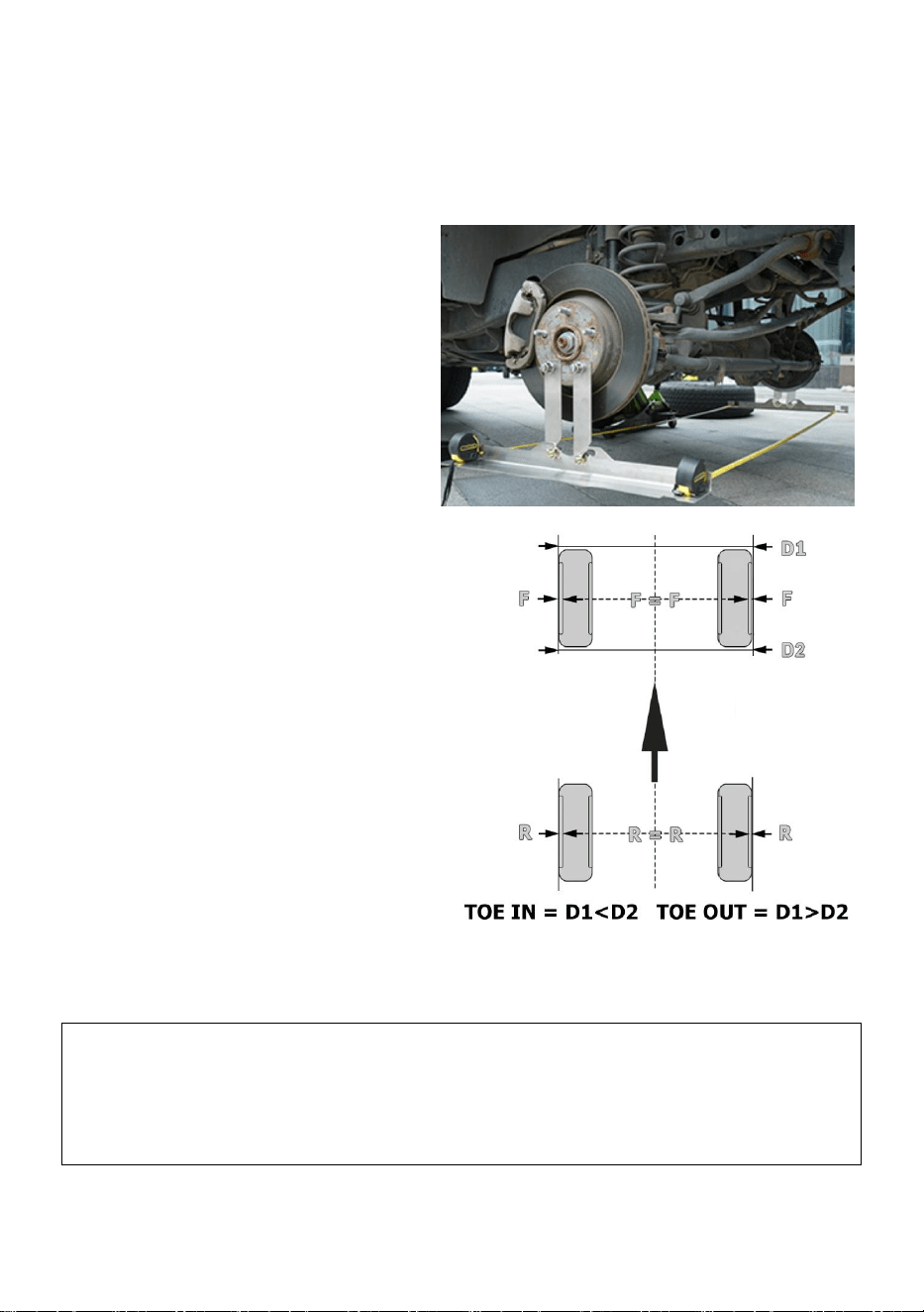
Step5.Run the tape measures
underneath the car as shown,
Unlock the tape measures and slide
them into the slots. DO NOT re-lock
the tape measures. Leaving them
unlocked will apply the proper
amount of tension. Pull on them
slightly and note the measurements.
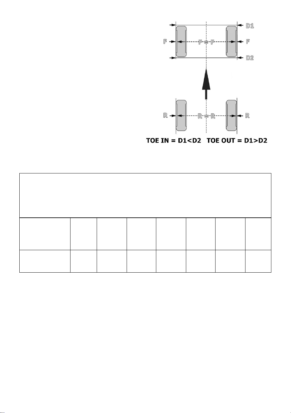
- 5 -
Step6.The rear tape measurement
(side towards the rear of the vehicle)
minus the front tape
measurement(side closest to the front
of the vehicle) is the total toe of the
axle. A larger measurement on the
front side indicates toe out, and a
larger measurement on the rear side
indicates toe in.
For example, if the front measurement
D1 is 66” and the rear measurement
D2 is 66 3/32 the axle has a total toe in
of 3/32”
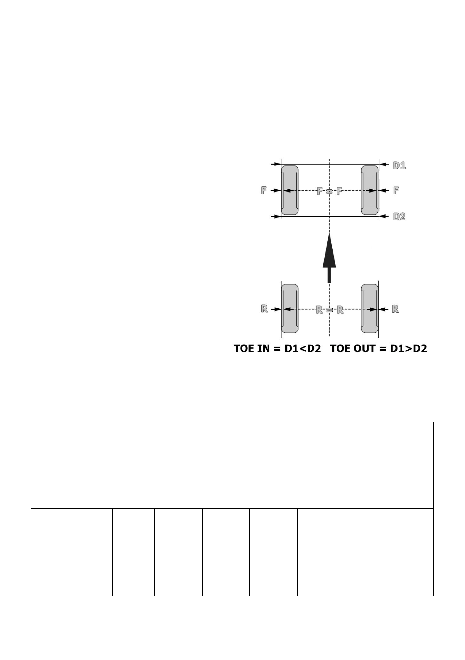
TOE PLATE DEGREES TO INCH CONVERSION CHART
Example: If the vehicle specs specify 0.4 degrees the toe should be half
way between 1/8”and 3/16” measured by the toe plates.
Degrees
Specification
0
0.16
0.32
0.48
0.64
0.8
0.96
Equivalent
0
1/16”
1/8”
3/16”
1/4”
5/16”
3/8”
Note: When using alignment specs, note that the toe plates measure the
TOTAL toe, not the toe of each wheel. Thus, if your specs are given for each
wheel, you will need to add those values together.
For example, if the toe-in of each wheel is supposed to be 0.15 degrees, then the
total toe should be 0.15+0.15= 0.3 degrees.
The optional alignment specs give total toe, so these specs do not need
modification; however, you should use the degree specifications, NOT the inch
specifications.

- 6 -
Tip: If the toe is correct, but the steering wheel is crooked, turn the tire rod
on one side in and the tie rod on the other side out an equal number of turns.
This will keep the toe measurement but adjust the position of the steering
wheel. Make sure to adjust it in the right direction!
Manufacturer: Shanghaimuxinmuyeyouxiangongsi
Address: Shuangchenglu 803nong11hao1602A-1609shi, baoshanqu,
shanghai 200000 CN.
Imported to AUS: SIHAO PTY LTD. 1 ROKEVA STREETEASTWOOD
NSW 2122 Australia
Imported to USA: Sanven Technology Ltd. Suite 250, 9166 Anaheim
Place, Rancho Cucamonga, CA 91730
REP
UK
YH CONSULTING LIMITED. C/O YH Consulting
Limited Office 147, Centurion House, London
Road, Staines-upon-Thames, Surrey, TW18 4AX
REP
EC
E-CrossStu GmbH
Mainzer Landstr.69,
60329 Frankfurt am Main.

- 1 -

- 2 -
OUTILS D'ALIGNEMENT ET D'ÉQUILIBRAGE
DES ROUES
MODÈLE : YL-716

- 1 -
MODÈLE : YL-716
< Image à titre indicatif uniquement >
Ceci est le mode d'emploi d'origine. Veuillez lire attentivement toutes les
instructions du manuel avant utilisation. VEVOR se réserve le droit
d'interpréter clairement ce manuel d'utilisation. L'apparence du produit
dépend du produit que vous avez reçu. Veuillez nous excuser pour le
retard dans la publication de toute mise à jour technologique ou logicielle
concernant notre produit.
WHEEL ALIGNMENT &
BALANCING TOOLS

- 2 -
MESURES DE SÉCURITÉ IMPORTANTES
AVERTISSEMENT : Veuillez lire attentivement et comprendre
l'intégralité de ce manuel avant d'utiliser ou d'entretenir ce
produit. Le non-respect de ces avertissements et instructions
peut entraîner des blessures corporelles ou des dommages
matériels.
9. Assemblez uniquement conformément à ces instructions. Un
assemblage incorrect peut créer des dangers.
10. Portez des lunettes de sécurité approuvées ANSI et des gants de
travail robustes pendant l’assemblage.
11. Gardez la zone de montage propre et bien éclairée.
12. Gardez les spectateurs hors de la zone pendant le montage.
13. Ne vous assemblez pas lorsque vous êtes fatigué ou sous l’influence
de l’alcool, de drogues ou de médicaments.
14. Les capacités du produit s'appliquent uniquement au produit
correctement et entièrement assemblé.
15. Évitez que les enfants n'utilisent le système d'alignement des roues .
Ce produit n'est pas un jouet. Ne laissez pas les enfants jouer avec .
16. Pour plus d'informations sur les pièces listées dans les pages
suivantes, veuillez vous référer au schéma d'assemblage de ce manuel.
Déballez et séparez toutes les pièces dans un espace de travail propre.
Veuillez conserver les petites pièces de rechange hors de portée des
enfants.
CONSERVEZ CES INSTRUCTIONS

- 3 -
LISTE DES PAQUETS
No
n.
Nom
Description
Photo
Qté
1
Plaque allongée
/
4
2
Plaque de référence
L=610mm
2
3
boulon hexagonal
M12*30
/
4
4
Noix
M12
/
4
5
Joints
12
/
4
6
Mètre à ruban
3 m ( 10 pi)
/
2
7
Manuel
/
/
1
Étapes d' installation
Étape 1. Installez la plaque
étendue en
alignant les connecteurs encastrés inclus
avec les emplacements des goujons de
roue, en vous assurant qu'ils sont
solidement
fixés aux goujons tout en
gardant l'installation fluide et stable.
- 4 -
Étape 2. Fixez le panneau d'outils
d'alignement des roues au connecteur à
encoche sécurisé et fixez le panneau
d'alignement en place à l'aide de l'écrou
avec le connecteur à encoche parallèle au
sol .
Étape 3. Utilisez un niveau (non fourni)
pour ajuster la plaque de référence à
l'horizontale, de l'avant vers l'arrière, afin
d'obtenir une mesure plus précise. Serrez
ensuite les vis. (Assurez-vous que les vis
situées à l'avant du véhicule sont bien
fixées au point le plus bas des trous du
panneau.)
Étape 4. Répétez les mêmes étapes sur les côtés opposés du pneu.
Si le châssis de votre véhicule est suffisamment haut, vous pouvez
également installer directement la plaque de référence sur le
- 5 -
roulement du moyeu sans utiliser de plaque d'extension.
Étape 5. Passez le mètre ruban
sous la voiture comme indiqué.
Déverrouillez-le et glissez-le dans
les fentes. NE reverrouillez PAS le
mètre ruban . Déverrouillés, ils
appliqueront la tension adéquate.
Tirez légèrement dessus et notez la
mesures.
Étape 6. La mesure du ruban arrière
(côté arrière du véhicule) moins la
mesure du ruban avant (côté le plus
proche de l'avant du véhicule) donne
le pincement total de l'essieu. Une
mesure plus grande à l'avant le côté
indique l'orteil vers l'extérieur, et une
mesure plus grande sur le côté arrière
indique l'orteil vers l'intérieur.
Par exemple, si la mesure avant D1
est de 66 pouces et la mesure arrière
D2 est de 66 3/32, l'essieu a un total
orteil de 3/32”
TABLEAU DE CONVERSION DES DEGRÉS DE LA PLAQUE D'EMBOUT EN
POUCES
Exemple : si les spécifications du véhicule précisent 0,4 degré l'orteil doit
être à mi-chemin entre 1/8 ” et 3/16 ” mesuré par les plaques d'orteils.
Diplômes
Spécification
0
0,16
0,32
0,48
0,64
0,8
0,96

- 6 -
Équivalent
0
1/16 ”
1/8 ”
3/16 ”
1/4 ”
5/16 ”
3/8 ”
Remarque : Lorsque vous utilisez des spécifications d'alignement, notez
que les plaques de butée mesurent la butée TOTALE, et non la butée de
chaque roue. Ainsi, si vos spécifications sont données pour chaque roue,
vous devrez additionner ces valeurs .
Par exemple, si le pincement de chaque roue est censé être de 0,15 degré, alors
le pincement total doit être de 0,15 + 0,15 = 0,3 degré.
Les spécifications d'alignement facultatives donnent le pincement total, ces
spécifications n'ont donc pas besoin d'être modifiées ; cependant, vous devez
utiliser les spécifications en degrés, PAS les spécifications en pouces .
Conseil : Si le pincement est correct, mais que le volant est tordu, tournez la
tige de direction d'un côté vers l'intérieur et la tige de direction de l'autre
côté du même nombre de tours. Cela conservera le pincement, mais ajustera
la position du volant. Veillez à le régler dans le bon sens !
Fabricant : Shanghaimuxinmuyeyouxiangongsi
Adresse : Shuangchenglu 803nong11hao1602A-1609shi, baoshanqu,
Shanghai 200 000 CN.
Importé en Australie : SIHAO PTY LTD. 1 ROKEVA STREET, ASTWOOD
NSW 2122 Australie
Importé aux États-Unis : Sanven Technology Ltd. Suite 250, 9166
Anaheim
Lieu, Rancho Cucamonga, CA 91730
REP
UK
YH CONSULTING LIMITED. C/O YH Consulting
Limited Office 147, Centurion House, London
Road, Staines-upon-Thames, Surrey, TW18 4AX
REP
EC
E-CrossStu GmbH
Mainzer Landstr.69,
60329 Frankfurt am Main.

- 7 -

- 1 -

- 2 -
WERKZEUGE ZUR ACHSVERMESSUNG UND
ZUM AUSWUCHTEN
MODELL: YL-716

- 1 -
MODELL: YL-716
< Bild nur als Referenz >
Dies ist die Originalanleitung. Bitte lesen Sie alle Anweisungen sorgfältig
durch, bevor Sie das Gerät in Betrieb nehmen. VEVOR behält sich eine
klare Auslegung unserer Bedienungsanleitung vor. Das Aussehen des
Produkts hängt vom gelieferten Produkt ab. Bitte haben Sie Verständnis
dafür, dass wir Sie nicht erneut über Technologie- oder Software-Updates
informieren.
WHEEL ALIGNMENT &
BALANCING TOOLS

- 2 -
WICHTIGE SICHERHEITSHINWEISE
WARNUNG: Lesen Sie das gesamte Handbuch, bevor Sie
dieses Produkt bedienen oder warten. Die Nichtbeachtung
dieser Warnungen und Anweisungen kann zu Verletzungen
oder Sachschäden führen.
17. Führen Sie die Montage ausschließlich gemäß dieser Anleitung durch.
Eine unsachgemäße Montage kann zu Gefahren führen.
18. Tragen Sie während der Montage eine ANSI-zugelassene Schutzbrille
und strapazierfähige Arbeitshandschuhe.
19. Halten Sie den Versammlungsbereich sauber und gut beleuchtet.
20. Halten Sie während der Montage unbeteiligte Personen vom Bereich
fern.
21. Montieren Sie nicht, wenn Sie müde sind oder unter dem Einfluss von
Alkohol, Drogen oder Medikamenten stehen.
22. Die Produktfunktionen gelten nur für ordnungsgemäß und vollständig
montierte Produkte.
23. des Achsmesssystems durch Kinder . Dieses Produkt ist kein
Spielzeug. Erlauben Sie Kindern nicht, damit zu spielen .
24. Weitere Informationen zu den auf den folgenden Seiten aufgeführten
Teilen finden Sie im Montageplan dieser Anleitung. Packen Sie alle Teile an
einem sauberen Arbeitsplatz aus und trennen Sie sie voneinander.
Bewahren Sie kleine Ersatzteile außerhalb der Reichweite von Kindern
auf.
BEWAHREN SIE DIESE ANWEISUNGEN AUF
- 3 -
PAKETLISTE
NEI
N.
Name
Beschreibung
Bild
MEN
GE
TY
1
Erweiterte Platte
/
4
2
Referenzplatte
L=610mm
2
3
Sechskantschraube
M12*30
/
4
4
Nuss
M12
/
4
5
Dichtungen
12
/
4
6
Bandmaß
3 m ( 10 Fuß)
/
2
7
Handbuch
/
/
1
Installationsschritte
Schritt 1. Installieren Sie die
erweiterte
Platte, indem Sie die mitgelieferten
versenkten Anschlüsse an den
Radbolzenpositionen ausrichten und
sicherstellen, dass sie sicher an den
Bolzen befestigt sind, während die
Installation reibungslos und stabil
bleibt .
- 4 -
Schritt 2. Befestigen Sie die
Radausrichtungswerkzeugplatte am
gesicherten Kerbverbinder und befestigen
Sie die Ausrichtungsplatte mit der Mutter,
wobei der Kerbverbinder parallel zum
Boden ist .
Schritt 3. Verwenden Sie eine
Wasserwaage (nicht im Lieferumfang
enthalten), um die Referenzplatte von
vorne nach hinten waagerecht
auszurichten, damit der Messwert genauer
wird. Ziehen Sie dann die Schrauben fest.
(Stellen Sie sicher, dass die Schrauben in
der Nähe der Fahrzeugfront am tiefsten
Punkt der Plattenlöcher befestigt sind.)
Schritt 4. Wiederholen Sie die gleichen Schritte auf den
gegenüberliegenden Seiten des Reifens.
- 5 -
Wenn das Fahrgestell Ihres Fahrzeugs hoch genug ist, können Sie
die Referenzplatte auch direkt auf dem Radlager montieren, ohne eine
Verlängerungsplatte zu verwenden.
Schritt 5. Führen Sie die
Maßbänder wie gezeigt unter dem
Auto entlang. Entriegeln Sie die
Maßbänder und schieben Sie sie in
die Schlitze. Verriegeln Sie die
Maßbänder NICHT wieder.
Verlassen Wenn sie entriegelt sind,
wird die richtige Spannung
aufgebracht. Ziehen Sie leicht daran
und beachten Sie die Messungen.
Schritt 6. Das hintere Maß (Seite
zum Fahrzeugheck) abzüglich des
vorderen Maßbandes (Seite zur
Fahrzeugfront) ergibt die Gesamtspur
der Achse. Ein größeres Maß an der
Vorderachse Seite zeigt die Nachspur
an, und ein größerer Wert auf der
Rückseite zeigt die Nachspur an.
Wenn beispielsweise das vordere Maß
D1 66" und das hintere Maß D2 66
3/32 beträgt, hat die Achse insgesamt
Vorspur von 3/32 Zoll
UMRECHNUNGSTABELLE VON GRAD IN ZOLL
Beispiel: Wenn die Fahrzeugspezifikationen 0,4 Grad vorschreiben die
Zehe sollte auf halbem Weg zwischen 1/8 " und 3/16 " liegen gemessen an
den Zehenplatten.

- 6 -
Abschlüsse
Spezifikation
0
0,16
0,32
0,48
0,64
0,8
0,96
Äquivalent
0
1/16
Zoll
1/8
Zoll
3/16
Zoll
1/4
Zoll
5/16
Zoll
3/8
Zoll
Hinweis : Beachten Sie bei der Verwendung von Achsmesswerten, dass die
Spurplatten die GESAMTSpur messen, nicht die Spur jedes einzelnen Rads.
Wenn Ihre Werte also für jedes Rad angegeben sind, müssen Sie diese
Werte addieren .
beispielsweise die Vorspur jedes Rads 0,15 Grad betragen soll, dann sollte die
Gesamtspur 0,15 + 0,15 = 0,3 Grad betragen.
Die optionalen Ausrichtungsspezifikationen geben die Gesamtspur an, sodass
diese Spezifikationen nicht geändert werden müssen. Sie sollten jedoch die
Gradspezifikationen und NICHT die Zollspezifikationen verwenden .
Tipp : Wenn die Spur korrekt ist, das Lenkrad aber schief steht, drehen Sie
die Spurstange auf der einen Seite nach innen und die Spurstange auf der
anderen Seite um die gleiche Anzahl Umdrehungen nach außen. Dadurch
bleibt die Spur erhalten, die Lenkradposition wird jedoch korrigiert. Achten
Sie auf die richtige Einstellung !
Hersteller: Shanghaimuxinmuyeyouxiangongsi
Adresse: Shuangchenglu 803nong11hao1602A-1609shi, baoshanqu,
Shanghai 200000 CN.
Importiert nach AUS: SIHAO PTY LTD. 1 ROKEVA STREETEASTWOOD
NSW 2122 Australien
Importiert in die USA: Sanven Technology Ltd. Suite 250, 9166 Anaheim
Place, Rancho Cucamonga, CA 91730

- 7 -
REP
UK
YH CONSULTING LIMITED. C/O YH Consulting
Limited Office 147, Centurion House, London
Road, Staines-upon-Thames, Surrey, TW18 4AX
REP
EC
E-CrossStu GmbH
Mainzer Landstr.69,
60329 Frankfurt am Main.

- 1 -

- 2 -
STRUMENTI PER L'ALLINEAMENTO E
L'EQUILIBRATURA DELLE RUOTE
MODELLO: YL-716

- 1 -
MODELLO: YL-716
< Immagine solo per riferimento >
Queste sono le istruzioni originali, si prega di leggere attentamente tutte le
istruzioni del manuale prima dell'uso. VEVOR si riserva la piena
interpretazione del proprio manuale utente. L'aspetto del prodotto
dipenderà dal prodotto ricevuto. Vi preghiamo di scusarci se non vi
informeremo più in caso di aggiornamenti tecnologici o software sul nostro
prodotto.
WHEEL ALIGNMENT &
BALANCING TOOLS

- 2 -
IMPORTANTI MISURE DI SICUREZZA
AVVERTENZA: Leggere attentamente l'intero manuale prima
di utilizzare o effettuare la manutenzione del prodotto. La
mancata osservanza di queste avvertenze e istruzioni può
causare lesioni personali o danni a beni di valore.
25. Montare solo secondo queste istruzioni. Un montaggio improprio può
comportare pericoli.
26. Durante il montaggio, indossare occhiali di sicurezza omologati ANSI e
guanti da lavoro resistenti.
27. Mantenere l'area di assemblaggio pulita e ben illuminata.
28. Durante l'assemblea, tenere gli astanti lontani dall'area.
29. Non riunirsi quando si è stanchi o sotto l'effetto di alcol, droghe o
medicinali.
30. Le capacità del prodotto si applicano solo al prodotto correttamente e
completamente assemblato.
31. Evitare che i bambini utilizzino il sistema di allineamento delle ruote .
Questo prodotto non è un giocattolo. Non permettere ai bambini di
giocarci .
32. Per ulteriori informazioni sui componenti elencati nelle pagine seguenti,
fare riferimento allo schema di montaggio di questo manuale. Disimballare
e separare tutti i componenti in un'area di lavoro pulita. Tenere i ricambi di
piccole dimensioni fuori dalla portata dei bambini.
CONSERVARE QUESTE ISTRUZIONI
- 3 -
ELENCO DEI PACCHETTI
NO.
Nome
Descrizione
Foto
Q
TY
1
Piastra estesa
/
4
2
Piastra di riferimento
L=610mm
2
3
Bullone esagonale
M12*30
/
4
4
Noce
M12
/
4
5
Guarnizioni
12
/
4
6
metro a nastro
3 m ( 10 piedi)
/
2
7
Manuale
/
/
1
Fasi di installazione
Fase 1. Installare la piastra
estesa
,
allineando i connettori incassati inclusi
con le posizioni dei perni della ruota,
assicurandosi che siano fissati
saldamente ai perni e mantenendo
l'installazione fluida e stabile.
Fase 2. Collegare il pannello dello
strumento di allineamento delle ruote al
connettore a tacca fissato e fissare il

- 4 -
pannello di allineamento in
posizione utilizzando il dado con il
connettore a tacca parallelo al
terreno .
Fase 3. Utilizzare una livella (non inclusa)
per regolare la piastra di riferimento in
posizione orizzontale da davanti a dietro,
in modo che il valore della misurazione sia
più preciso. Quindi serrare le viti.
(Assicurarsi che le viti vicino alla parte
anteriore del veicolo siano fissate nel
punto più basso dei fori del pannello)
Fase 4. Ripetere gli stessi passaggi sui lati opposti dello pneumatico.
Se il telaio del veicolo è sufficientemente alto, è possibile installare la
piastra di riferimento
direttamente sul cuscinetto del
mozzo senza utilizzare una
piastra di estensione.
Fase 5. Far passare i metri a nastro
- 5 -
sotto l'auto come mostrato, sbloccare i
metri a nastro e farli scorrere nelle fessure.
NON ribloccare i metri a nastro. Lasciare
sbloccandoli si applicherà la giusta
quantità di tensione. Tirateli leggermente
e notate la misurazioni.
Fase 6. La misura del nastro
posteriore (lato rivolto verso la parte
posteriore del veicolo) meno la misura
del nastro anteriore (lato più vicino alla
parte anteriore del veicolo) è la
convergenza totale dell'asse. Una
misura maggiore sulla parte anteriore
Il lato indica la punta verso l'esterno,
mentre una misura più grande sul lato
posteriore indica la punta verso
l'interno.
Ad esempio, se la misura anteriore D1
è 66" e la misura posteriore D2 è 66 3/32
l'asse ha un totale punta verso l'interno 3/32"
TABELLA DI CONVERSIONE DA GRADI A POLLICI DELLA PIASTRA
CONDENSAZIONE
Esempio: se le specifiche del veicolo specificano 0,4 gradi la punta
dovrebbe essere a metà strada tra 1/8 " e 3/16 " misurata dalle piastre delle
dita.
Gradi
Specifica
0
0,16
0,32
0,48
0,64
0,8
0,96
Equivalente
0
1/16 "
1/8 "
3/16 ”
1/4 "
5/16 ”
3/8 "

- 6 -
Nota : quando si utilizzano le specifiche di allineamento, tenere presente che
le piastre di convergenza misurano la convergenza TOTALE, non la
convergenza di ciascuna ruota. Pertanto, se le specifiche sono fornite per
ciascuna ruota, sarà necessario sommare tali valori .
Ad esempio, se si suppone che la convergenza di ciascuna ruota sia di 0,15 gradi,
la convergenza totale dovrebbe essere 0,15+0,15= 0,3 gradi.
Le specifiche di allineamento opzionali forniscono la convergenza totale, quindi
non necessitano di modifiche; tuttavia, è necessario utilizzare le specifiche in gradi,
NON quelle in pollici .
Suggerimento : se la convergenza è corretta, ma il volante è storto, ruotare il
tirante dello pneumatico da un lato verso l'interno e il tirante dall'altro lato
verso l'esterno di un numero uguale di giri. In questo modo si manterrà la
convergenza, ma si regolerà la posizione del volante. Assicurarsi di
regolarlo nella direzione corretta !
Produttore: Shanghaimuxinmuyeyouxiangongsi
Indirizzo: Shuangchenglu 803nong11hao1602A-1609shi, baoshanqu,
Shanghai 200000 CN.
Importato in AUS: SIHAO PTY LTD. 1 ROKEVA STREETEASTWOOD
Nuovo Galles del Sud 2122 Australia
Importato negli USA: Sanven Technology Ltd. Suite 250, 9166 Anaheim
Luogo, Rancho Cucamonga, CA 91730
REP
UK
YH CONSULTING LIMITED. C/O YH Consulting
Limited Office 147, Centurion House, London
Road, Staines-upon-Thames, Surrey, TW18 4AX
REP
EC
E-CrossStu GmbH
Mainzer Landstr.69,
60329 Frankfurt am Main.

- 7 -

- 1 -

- 2 -
HERRAMIENTAS DE ALINEACIÓN Y
BALANCEO DE RUEDAS
MODELO: YL-716

- 1 -
MODELO: YL-716
< Imagen solo como referencia >
Estas son las instrucciones originales; lea atentamente todas las
instrucciones del manual antes de utilizarlo. VEVOR se reserva el derecho
de interpretar su manual de usuario. La apariencia del producto dependerá
del producto que haya recibido. Le rogamos que nos disculpe si no le
informamos de nuevo si hay actualizaciones tecnológicas o de software en
nuestro producto.
WHEEL ALIGNMENT &
BALANCING TOOLS

- 2 -
MEDIDAS DE SEGURIDAD IMPORTANTES
ADVERTENCIA: Lea y comprenda completamente este
manual antes de operar o realizar tareas de mantenimiento en
este producto. El incumplimiento de estas advertencias e
instrucciones puede causar lesiones personales o daños a
bienes valiosos.
33. Ensamble únicamente según estas instrucciones. Un montaje
incorrecto puede causar riesgos.
34. Use gafas de seguridad aprobadas por ANSI y guantes de trabajo
resistentes durante el montaje.
35. Mantenga el área de reunión limpia y bien iluminada.
36. Mantenga a los transeúntes fuera del área durante el montaje.
37. No se reúna cuando esté cansado o bajo la influencia del alcohol,
drogas o medicamentos.
38. Las capacidades del producto se aplican únicamente a productos
ensamblados de manera correcta y completa.
39. Evite que los niños utilicen el sistema de alineación de ruedas . Este
producto no es un juguete. No permita que los niños jueguen con él .
40. Para obtener más información sobre las piezas que se listan en las
páginas siguientes, consulte el diagrama de montaje de este manual.
Desembale y separe todas las piezas en un área de trabajo limpia.
Mantenga las piezas de repuesto pequeñas fuera del alcance de los niños.
GUARDE ESTAS INSTRUCCIONES
- 3 -
LISTA DE PAQUETES
No.
Nombre
Descripción
Foto
Cant
idad
1
Placa extendida
/
4
2
Placa de referencia
Largo = 610
mm
2
3
Perno hexagonal
M12*30
/
4
4
Tuerca
M12
/
4
5
Juntas
12
/
4
6
Cinta métrica
3 m ( 10 pies)
/
2
7
Manual
/
/
1
Pasos de instalación
Paso 1. Instale la placa
extendida
,
alineando los conectores empotrados
incluidos con las ubicaciones de los
pernos de la rueda, asegurándose de
que estén bien fijados a los pernos
mientras se mantiene la instalación
suave y
estable
.
- 4 -
Paso 2. Conecte el panel de la
herramienta de alineación de
ruedas al conector de muesca
asegurado y asegure el panel de
alineación en su lugar usando la
tuerca con el conector de muesca
paralelo al suelo .
Paso 3. Use un nivel (no incluido) para
ajustar la placa de referencia
horizontalmente de adelante hacia atrás,
de modo que la medición sea más precisa.
A continuación, apriete los tornillos.
(Asegúrese de que los tornillos cerca de la
parte delantera del vehículo estén fijados
en el punto más bajo de los orificios del
panel).
Paso 4. Repita los mismos pasos en los lados opuestos del neumático.
Si el chasis de su vehículo es lo suficientemente alto, también puede
instalar directamente la placa de referencia en el cojinete del cubo sin
- 5 -
utilizar una placa de extensión.
Paso 5. Pase las cintas métricas
por debajo del automóvil como se
muestra. Desbloquee las cintas
métricas y deslícelas en las ranuras.
NO vuelva a bloquear las cintas
métricas. Si los desbloqueas,
aplicarás la tensión adecuada. Tira
de ellos ligeramente y observa la
mediciones.
Paso 6. La medida de la cinta trasera
(lado hacia la parte trasera del
vehículo) menos la medida de la cinta
delantera (lado más cercano a la parte
delantera del vehículo) es la
convergencia total del eje. Una medida
mayor en la parte delantera. El lado
indica la convergencia hacia afuera, y
una medida más grande en el lado
trasero indica la convergencia hacia
adentro.
Por ejemplo, si la medida delantera D1
es 66” y la medida trasera D2 es 66 3/32 el
eje tiene un total de convergencia de 3/32”
TABLA DE CONVERSIÓN DE GRADOS A PULGADAS DE LA PLACA DE
PUNTA
Ejemplo: Si las especificaciones del vehículo especifican 0,4 grados La
punta debe estar a medio camino entre 1/8 ” y 3/16 ” medido por las
placas de los dedos.

- 6 -
Grados
Especificación
0
0.16
0.32
0.48
0.64
0.8
0,96
Equivalente
0
1/16 ”
1/8 ”
3/16 ”
1/4 ”
5/16 ”
3/8 ”
Nota : Al usar las especificaciones de alineación, tenga en cuenta que las
placas de convergencia miden la convergencia total, no la convergencia de
cada rueda. Por lo tanto, si las especificaciones corresponden a cada rueda,
deberá sumar esos valores .
Por ejemplo, si se supone que la convergencia de cada rueda debe ser de 0,15
grados, entonces la convergencia total debe ser 0,15 + 0,15 = 0,3 grados.
Las especificaciones de alineación opcionales brindan la convergencia total, por
lo que no es necesario modificarlas; sin embargo, debe utilizar las
especificaciones en grados, NO las especificaciones en pulgadas .
Consejo : Si la convergencia es correcta, pero el volante está torcido, gire la
barra de dirección de un lado hacia adentro y la barra de dirección del otro
hacia afuera un número igual de vueltas. Esto mantendrá la convergencia,
pero ajustará la posición del volante. ¡Asegúrese de ajustarlo en la dirección
correcta !
Fabricante: Shanghaimuxinmuyeyouxiangongsi
Dirección: Shuangchenglu 803nong11hao1602A-1609shi, baoshanqu,
Shanghái 200000 CN.
Importado a AUS: SIHAO PTY LTD. 1 ROKEVA STREET, EASTWOOD
NSW 2122 Australia
Importado a EE. UU.: Sanven Technology Ltd. Suite 250, 9166 Anaheim
Lugar, Rancho Cucamonga, CA 91730

- 7 -
REP
UK
YH CONSULTING LIMITED. C/O YH Consulting
Limited Office 147, Centurion House, London
Road, Staines-upon-Thames, Surrey, TW18 4AX
REP
EC
E-CrossStu GmbH
Mainzer Landstr.69,
60329 Frankfurt am Main.

- 1 -

- 2 -
NARZĘDZIA DO USTAWIANIA GEOMETRII I
WYWAŻANIA KÓŁ
MODEL: YL-716

- 1 -
MODEL: YL-716
< Zdjęcie tylko w celach poglądowych >
To jest oryginalna instrukcja obsługi. Przed użyciem prosimy o dokładne
zapoznanie się z treścią instrukcji. Firma VEVOR zastrzega sobie prawo
do jednoznacznej interpretacji niniejszej instrukcji obsługi. Wygląd
produktu zależy od stanu, w jakim go otrzymali Państwo. Prosimy o
wyrozumiałość, ale nie będziemy Państwa ponownie informować o
aktualizacjach technologicznych lub oprogramowania naszego produktu.
WHEEL ALIGNMENT &
BALANCING TOOLS

- 2 -
WAŻNE ZABEZPIECZENIA
OSTRZEŻENIE: Przed rozpoczęciem użytkowania lub
serwisowania produktu należy przeczytać i zrozumieć całą
instrukcję. Nieprzestrzeganie tych ostrzeżeń i instrukcji może
spowodować obrażenia ciała lub uszkodzenie cennego
mienia.
41. Montaż należy wykonywać wyłącznie zgodnie z niniejszą instrukcją.
Nieprawidłowy montaż może stwarzać zagrożenie.
42. Podczas montażu należy nosić okulary ochronne zatwierdzone przez
ANSI oraz wytrzymałe rękawice robocze.
43. Utrzymuj miejsce zgromadzeń w czystości i zapewnij dobre
oświetlenie.
44. Nie dopuszczać osób postronnych na teren montażu w trakcie jego
trwania.
45. Nie należy gromadzić się, gdy jest się zmęczonym lub pod wpływem
alkoholu, narkotyków lub leków.
46. Możliwości produktu odnoszą się wyłącznie do produktu prawidłowo i
całkowicie zmontowanego.
47. Unikaj korzystania z systemu ustawiania geometrii kół przez dzieci .
Ten produkt nie jest zabawką. Nie pozwalaj dzieciom bawić się nim .
48. Aby uzyskać dodatkowe informacje dotyczące części wymienionych
na kolejnych stronach, zapoznaj się ze schematem montażu w niniejszej
instrukcji. Rozpakuj i rozdziel wszystkie części w czystym miejscu pracy.
Małe części zamienne przechowuj poza zasięgiem dzieci.
ZACHOWAJ TE INSTRUKCJE

- 3 -
LISTA PAKIETÓW
NIE
.
Nazwa
Opis
Zdjęcie
Ilość
TY
1
Wydłużona płyta
/
4
2
Płytka odniesienia
Długość = 610
mm
2
3
Śruba sześciokątna
M12*30
/
4
4
Nakrętka
M12
/
4
5
Uszczelki
12
/
4
6
Taśma miernicza
3 m ( 10 stóp)
/
2
7
Podręcznik
/
/
1
Kroki instalacji
Krok 1. Zamontuj
przedłużoną płytę,
dopasowując dołączone wpuszczane
łączniki do lokalizacji szpilek koła,
upewniając się, że są one solidnie
przymocowane do szpilek, a montaż
przebiega płynnie i stabilnie.
- 4 -
Krok 2. Zamocuj panel narzędzia do
ustawiania geometrii kół do
zabezpieczonego łącznika z wycięciem i
zabezpiecz panel na miejscu za pomocą
nakrętki, tak aby łącznik z wycięciem był
równoległy do podłoża .
Krok 3. Za pomocą poziomicy (brak w
zestawie) ustaw płytę odniesienia w
pozycji poziomej, od przodu do tyłu, aby
uzyskać dokładniejszy pomiar. Następnie
dokręć śruby (upewnij się, że śruby z
przodu pojazdu są dokręcone w
najniższym punkcie otworów w panelu).
Krok 4. Powtórz te same czynności po przeciwnych stronach opony.
Jeżeli podwozie Twojego pojazdu jest wystarczająco wysokie,
możesz także zamontować płytkę odniesienia bezpośrednio na
łożysku piasty, bez użycia płytki przedłużającej.
- 5 -
Krok 5. Przełóż taśmy miernicze
pod samochodem, jak pokazano na
rysunku. Odblokuj taśmy miernicze i
wsuń je w szczeliny. NIE blokuj taśm
mierniczych ponownie. Pozostaw
Odblokowanie ich spowoduje
naciągnięcie odpowiedniej ilości
materiału. Pociągnij je lekko i zwróć
uwagę na pomiary.
Krok 6. Pomiar taśmy tylnej (strona
skierowana do tyłu pojazdu)
pomniejszony o pomiar taśmy
przedniej (strona bliższa przodu
pojazdu) stanowi całkowity zbieżność
osi. Większy pomiar z przodu bok
oznacza stopę skierowaną na
zewnątrz, a większy pomiar z tyłu
oznacza stopę skierowaną do
wewnątrz.
Na przykład, jeśli przedni wymiar D1
wynosi 66”, a tylny wymiar D2 wynosi
66 3/32, oś ma całkowitą palec u nogi 3/32”
TABELA KONWERSJI STOPNI NA CALE PŁYTY PRĘDKOŚCI
Przykład: Jeśli specyfikacja pojazdu określa 0,4 stopnia palec powinien
znajdować się w połowie odległości między 1/8 ” a 3/16 ” mierzone za
pomocą płytek palców.
Stopnie
Specyfikacja
0
0,16
0,32
0,48
0,64
0,8
0,96

- 6 -
Równowartość
0
1/16 ”
1/8
cala
3/16 ”
1/4
cala
5/16 ”
3/8
cala
Uwaga : Używając specyfikacji zbieżności, pamiętaj, że płytki mierzą
CAŁKOWITY zbieżność, a nie zbieżność każdego koła. Dlatego, jeśli
specyfikacja jest podana dla każdego koła, należy zsumować te wartości .
Na przykład, jeśli zbieżność każdego koła ma wynosić 0,15 stopnia, to całkowita
zbieżność powinna wynosić 0,15 + 0,15 = 0,3 stopnia.
Opcjonalne specyfikacje dotyczące wyrównania podają całkowitą wartość, dlatego
nie ma potrzeby ich modyfikowania; należy jednak używać specyfikacji podanych
w stopniach, a NIE w calach .
Wskazówka : Jeśli zbieżność jest prawidłowa, ale kierownica jest krzywa,
obróć drążek kierowniczy z jednej strony do wewnątrz, a drążek kierowniczy
z drugiej strony na zewnątrz o taką samą liczbę obrotów. To pozwoli
zachować zbieżność, ale wyreguluje położenie kierownicy. Upewnij się, że
regulacja jest wykonana we właściwym kierunku !
Producent: Shanghaimuxinmuyeyouxiangongsi
Adres: Shuangchenglu 803nong11hao1602A-1609shi, baoshanqu,
szanghaj 200000 CN.
Importowane do AUS: SIHAO PTY LTD. 1 ROKEVA
STREETEASTWOOD
NSW 2122 Australia
Importowane do USA: Sanven Technology Ltd. Suite 250, 9166 Anaheim
Miejsce, Rancho Cucamonga, CA 91730
REP
UK
YH CONSULTING LIMITED. C/O YH Consulting
Limited Office 147, Centurion House, London
Road, Staines-upon-Thames, Surrey, TW18 4AX
REP
EC
E-CrossStu GmbH
Mainzer Landstr.69,
60329 Frankfurt am Main.

- 7 -

- 1 -

- 2 -
GEREEDSCHAP VOOR WIELUITLIJNING EN
BALANCEREN
MODEL: YL-716

- 1 -
MODEL: YL-716
< Afbeelding alleen ter referentie >
Dit is de originele handleiding. Lees alle instructies zorgvuldig door voordat
u het product gebruikt. VEVOR behoudt zich het recht voor om de
gebruiksaanwijzing duidelijk te interpreteren. Het uiterlijk van het product is
afhankelijk van het product dat u hebt ontvangen. Neemt u het ons niet
kwalijk dat we u niet meer op de hoogte stellen van eventuele
technologische of software-updates voor ons product.
WHEEL ALIGNMENT &
BALANCING TOOLS

- 2 -
BELANGRIJKE VEILIGHEIDSMAATREGELEN
WAARSCHUWING: Lees deze volledige handleiding
zorgvuldig door voordat u dit product bedient of onderhoudt.
Het niet opvolgen van deze waarschuwingen en instructies
kan leiden tot persoonlijk letsel of schade aan waardevolle
eigendommen.
49. Monteer uitsluitend volgens deze instructies. Onjuiste montage kan
gevaarlijk zijn.
50. Draag tijdens de montage een ANSI-goedgekeurde veiligheidsbril en
stevige werkhandschoenen.
51. Zorg ervoor dat de verzamelplaats schoon en goed verlicht is.
52. Houd omstanders tijdens de montage uit de buurt.
53. Kom niet in actie als u moe bent of onder invloed van alcohol, drugs of
medicijnen.
54. De producteigenschappen gelden uitsluitend voor producten die
correct en volledig zijn gemonteerd.
55. Vermijd dat kinderen het wieluitlijnsysteem gebruiken . Dit product is
geen speelgoed. Laat kinderen er niet mee spelen .
56. Raadpleeg voor meer informatie over de onderdelen die op de
volgende pagina's worden vermeld het montageschema in deze
handleiding. Pak alle onderdelen uit en scheid ze van elkaar op een
schone werkplek. Houd kleine reserveonderdelen buiten bereik van
kinderen.
BEWAAR DEZE INSTRUCTIES
- 3 -
PAKKETLIJST
Ne
e.
Naam
Beschrijving
Foto
Aant
al
1
Verlengde plaat
/
4
2
Referentieplaat
Lengte = 610
mm
2
3
Zeshoekige bout
M12*30
/
4
4
Moer
M12
/
4
5
Pakkingen
12
/
4
6
Meetlint
3 m ( 10 ft)
/
2
7
Handmatig
/
/
1
Installatiestappen
Stap 1. Installeer de
verlengde
plaat en
lijn de meegeleverde verzonken
connectoren uit met de locaties van de
wielbouten. Zorg ervoor dat ze stevig
aan de bouten vastzitten en dat de
installatie soepel en stabiel verloopt .

- 4 -
Stap 2. Bevestig het
wieluitlijningsgereedschapspaneel aan de
beveiligde inkepingconnector en zet het
uitlijningspaneel vast met de moer, waarbij
de inkepingconnector parallel aan de
grond is .
Stap 3. Gebruik een waterpas (niet
meegeleverd) om de referentieplaat
horizontaal van voor naar achter te
plaatsen, zodat de meetwaarde
nauwkeuriger is. Draai vervolgens de
schroeven vast. (Zorg ervoor dat de
schroeven aan de voorkant van het
voertuig op het laagste punt van de
paneelgaten worden vastgezet.)
Stap 4. Herhaal dezelfde stappen aan de tegenovergestelde kanten van
de band.
- 5 -
Als het chassis van uw voertuig hoog genoeg is, kunt u de
referentieplaat ook rechtstreeks op het naaflager monteren, zonder
gebruik te maken van een verlengplaat.
Stap 5. Leg de meetlinten onder de
auto zoals afgebeeld. Ontgrendel de
meetlinten en schuif ze in de sleuven.
Vergrendel de meetlinten NIET
opnieuw . Als ze ontgrendeld zijn, zal
de juiste hoeveelheid spanning
worden toegepast. Trek er lichtjes
aan en let op de metingen.
Stap 6. De meting van het achterste
meetlint (zijde richting de achterkant
van het voertuig) minus de meting van
het voorste meetlint (zijde het dichtst
bij de voorkant van het voertuig) is de
totale sporing van de as. Een grotere
meting aan de voorkant De zijkant
geeft de teen naar buiten aan, en een
grotere meting aan de achterkant geeft
de teen naar binnen aan.
Als de voormaat D1 bijvoorbeeld 66
inch is en de achtermaat D2 66 3/32
inch, heeft de as een totale teen in van 3/32”
CONVERSIETABEL VAN GRADEN NAAR INCH VAN TEENPLAAT
Voorbeeld: Als de voertuigspecificaties 0,4 graden voorschrijven de teen
moet halverwege tussen 1/8 ” en 3/16 ” zijn gemeten door de teenplaten.

- 6 -
Graden
Specificatie
0
0,16
0,32
0,48
0,64
0,8
0,96
Equivalent
0
1/16 ”
1/8
inch
3/16 ”
1/4
inch
5/16 ”
3/8
inch
Let op: Houd er bij het gebruik van uitlijningsspecificaties rekening mee dat
de teenplaten de TOTALE teenuitslag meten, niet de teenuitslag van elk wiel.
Als uw specificaties voor elk wiel zijn opgegeven, moet u deze waarden dus
bij elkaar optellen .
Als de toe-in van elk wiel bijvoorbeeld 0,15 graden moet zijn, dan moet de totale
toe-in 0,15 + 0,15 = 0,3 graden zijn .
De optionele uitlijningsspecificaties geven de totale toespoor aan, dus deze
specificaties hoeven niet te worden aangepast. U dient echter de specificaties in
graden te gebruiken, NIET de specificaties in inches .
Tip : Als de sporing correct is, maar het stuur scheef staat, draai dan de
spoorstang aan de ene kant evenveel slagen naar binnen en de spoorstang
aan de andere kant evenveel slagen naar buiten. Hierdoor blijft de sporing
behouden, maar wordt de positie van het stuur aangepast. Zorg ervoor dat u
het in de juiste richting afstelt !
Fabrikant: Shanghaimuxinmuyeyouxiangongsi
Adres: Shuangchenglu 803nong11hao1602A-1609shi, baoshanqu,
shanghai 200000 CN.
Geïmporteerd naar AUS: SIHAO PTY LTD. 1 ROKEVA
STREETEASTWOOD
NSW 2122 Australië
Geïmporteerd naar de VS: Sanven Technology Ltd. Suite 250, 9166
Anaheim
Plaats, Rancho Cucamonga, CA 91730

- 7 -
REP
UK
YH CONSULTING LIMITED. C/O YH Consulting
Limited Office 147, Centurion House, London
Road, Staines-upon-Thames, Surrey, TW18 4AX
REP
EC
E-CrossStu GmbH
Mainzer Landstr.69,
60329 Frankfurt am Main.

- 1 -

- 2 -
HJULINSTÄLLNING OCH
BALANSERINGSVERKTYG
MODELL: YL-716
- 1 -
MODELL: YL-716
< Bilden är endast för referens >
Detta är originalinstruktionerna, vänligen läs alla instruktioner noggrant
innan du använder produkten. VEVOR förbehåller sig en tydlig tolkning av
vår användarmanual. Produktens utseende ska vara beroende av den
produkt du mottagit. Vi ber om ursäkt för att vi inte kommer att informera
dig igen om det finns några teknik- eller programuppdateringar för vår
produkt.
WHEEL ALIGNMENT &
BALANCING TOOLS

- 2 -
VIKTIGA SÄKERHETSÅTGÄRDER
VARNING: Läs och förstå hela denna manual innan du
använder eller utför service på denna produkt. Underlåtenhet
att följa dessa varningar och instruktioner kan orsaka
personskador eller skador på värdefull egendom.
57. Montera endast enligt dessa instruktioner. Felaktig montering kan
skapa risker.
58. Använd ANSI-godkända skyddsglasögon och kraftiga arbetshandskar
under monteringen.
59. Håll samlingsområdet rent och väl upplyst.
60. Håll åskådare borta från området under monteringen.
61. Montera inte när du är trött eller påverkad av alkohol, droger eller
mediciner.
62. Produktegenskaperna gäller endast korrekt och fullständigt monterade
produkter.
63. Undvik att barn använder hjulinställningssystemet . Och den här
produkten är inte en leksak. Låt inte barn leka .
64. För ytterligare information om delarna som listas på följande sidor, se
monteringsschemat i denna manual. Packa upp och separera alla delar på
en ren arbetsyta. Förvara små reservdelar utom räckhåll för barn.
SPARA DESSA INSTRUKTIONER
- 3 -
PAKETLISTA
Ing
a.
Namn
Beskrivning
Bild
Q
TY
1
Förlängd platta
/
4
2
Referensplatta
L=610 mm
2
3
Sexkantig bult
M12*30
/
4
4
Mutter
M12
/
4
5
Packningar
12
/
4
6
Måttband
3 m ( 10 fot)
/
2
7
Manuell
/
/
1
Installationssteg
Steg 1. Montera den förlängda plattan
och rikta in de medföljande försänkta
kontakterna med hjulbultarnas
placering. Se till att de är ordentligt
fästa vid bultarna samtidigt som
installationen hålls smidig och stabil .
Steg 2. Fäst hjulinställningspanelen på det
säkrade skårförbindningsdonet och fäst
inställningspanelen på plats med muttern
så att skårförbindningsdonet är parallellt
med marken .
- 4 -
Steg 3. Använd ett vattenpass (medföljer
ej) för att justera referensplattan till ett
horisontellt läge framifrån och bakåt, så att
mätvärdet blir mer exakt. Dra sedan åt
skruvarna. (se till att skruvarna nära
fordonets framsida är fästa vid den lägsta
punkten på panelhålen)
Steg 4. Upprepa samma steg på motsatta sidor av däcket.
Om ditt fordons chassi är tillräckligt högt kan du även montera
referensplattan direkt på navlagret utan att använda en
förlängningsplatta.
Steg 5. Trä måttbandet under bilen
som visas. Lås upp måttbandet och
skjut in det i skårorna. LÅS INTE fast
måttbandet igen. När de är upplåsta
kommer rätt mängd spänning att
appliceras. Dra lätt i dem och notera
mätningar.
Steg 6. Det bakre måttet på

- 5 -
axelbandet (sidan mot fordonets bakre del)
minus det främre måttet på axelbandet
(sidan närmast fordonets framdel) är axelns
totala tå. Ett större mått på framsidan sidan
indikerar tå ut, och ett större mått på
baksidan indikerar tå in.
Om till exempel det främre måttet D1 är 66”
och det bakre måttet D2 är 66 3/32 har axeln
totalt tå i 3/32”
TÅPLATTAN GRADER TILL TUM KONVERTERINGSTABELL
Exempel: Om fordonets specifikationer anger 0,4 grader Tån ska vara
halvvägs mellan 1/8 ” och 3/16 ” mätt med tåplattorna.
Grader
Specifikation
0
0,16
0,32
0,48
0,64
0,8
0,96
Ekvivalent
0
1/16 ”
1/8 ”
3/16 ”
1/4 ”
5/16 ”
3/8 ”
OBS ! När du använder justeringsspecifikationer, observera att tåplattorna
mäter den TOTALA tån, inte tån på varje hjul. Om dina specifikationer anges
för varje hjul måste du därför lägga ihop dessa värden .
Till exempel, om toe-in-vinkeln för varje hjul ska vara 0,15 grader, då bör den totala
toe-in-vinkeln vara 0,15 + 0,15 = 0,3 grader.
De valfria justeringsspecifikationerna anger total tå, så dessa specifikationer
behöver inte modifieras; du bör dock använda gradspecifikationerna, INTE
tumspecifikationerna .
Tips : Om tån är korrekt, men ratten är sned, vrid däckstången på ena sidan
inåt och dragstången på andra sidan utåt lika många varv. Detta behåller
tåmåttet men justerar rattens position. Se till att justera den i rätt riktning !

- 6 -
Tillverkare: Shanghaimuxinmuyeyouxiangongsi
Adress: Shuangchenglu 803nong11hao1602A-1609shi, baoshanqu,
Shanghai 200 000 kanadensiska republiken.
Importerad till Australien: SIHAO PTY LTD. 1 ROKEVA
STREETEASTWOOD
NSW 2122 Australien
Importerad till USA: Sanven Technology Ltd. Suite 250, 9166 Anaheim
Plats, Rancho Cucamonga, Kalifornien 91730
REP
UK
YH CONSULTING LIMITED. C/O YH Consulting
Limited Office 147, Centurion House, London
Road, Staines-upon-Thames, Surrey, TW18 4AX
REP
EC
E-CrossStu GmbH
Mainzer Landstr.69,
60329 Frankfurt am Main.