
3
Acknowledgement
Dear customers,
Thank you for purchasing Parsun products. We place great importance on efficiency, safety,
and comfort of our products. Before delivery, we conduct rigorous testing to optimize your
experience. Before using TM120B, please read this manual carefully to ensure its correct and
safe use.
You're seen as having read the contents of this manual after starting using TM120B. Please do
not lend TM120B to anyone that has not read this manual. Parsun is not responsible for any
accidental losses resulting from the failure in following the operations mentioned in this
manual.
This manual will be updated from time to time. Upon discovering that your product does not
match the contents of this manual, please do not hesitate to contact us via the official website
www.parsunpower.cn, and we will send you a satisfactory reply. This manual is available in
multiple languages, so the content may not be exactly the same. Parsun reserves the right to the
final interpretation of this manual.
We strive to continuously improve and optimize our products. For any suggestions on our
products, please feel free to contact us via the official website at www.parsunpower.cn.
Symbols
This manual contains some symbols. Please understand these symbols according to the
following meanings.
Warnings or special attention
Note
4
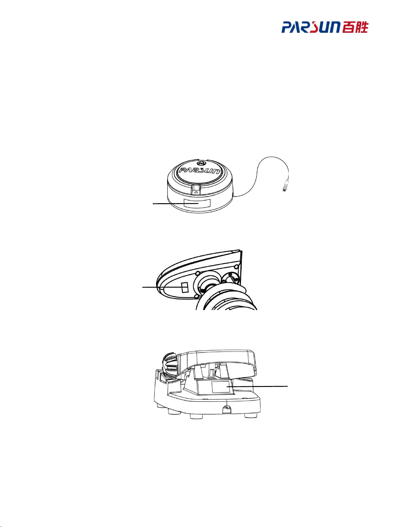
Nameplate
Nameplate
Nameplate
Product SN
TM120B consists of multiple components, of which S/N is printed on the machine's nameplate
and recorded at the S/N on the nameplate. It can help you order spare parts from your distributor,
and apply for product warranty services, and other after-sales services, and can also serve as a
reference once the machine is stolen. Please do not remove the nameplate.

5
Contents
Acknowledgement ..................................................................................................................... 3
Symbols ..................................................................................................................................... 3
Product SN................................................................................................................................. 4
1 Product Overview ................................................................................................................... 7
1.1 Safety instructions........................................................................................................ 7
1.1.1 Safety features ................................................................................................... 7
1.1.2 Precautions ........................................................................................................ 8
1.2 Packing list ................................................................................................................ 10
1.3 Parts ........................................................................................................................... 12
1.4 Specification .............................................................................................................. 13
1.5 Declaration of Conformity ......................................................................................... 14
2 Installation ............................................................................................................................ 16
2.1 Install the unit ............................................................................................................ 16
2.2 Install the propeller .................................................................................................... 18
2.3 Install the pedals (optional) and heading sensor (optional) ........................................ 18
2.4 Connect wiring harness .............................................................................................. 19
3 Unit ....................................................................................................................................... 20
3.1 Fold and unfold TM120B .......................................................................................... 20
3.2 Adjust height .............................................................................................................. 21
3.3 Panel .......................................................................................................................... 21
3.3.1 Power level indicator ...................................................................................... 22
3.4 Anti-tangling of spring wire ....................................................................................... 23
4 Pedal ..................................................................................................................................... 24
4.1 Steering ...................................................................................................................... 24
4.2 Momentary switch ..................................................................................................... 24
4.3 Level adjustment ........................................................................................................ 25
4.4 Continuous switch...................................................................................................... 25
4.5 Anchoring (electronic anchor) ................................................................................... 26
4.6 Bow/heading hold ...................................................................................................... 26
4.7 Steering calibration .................................................................................................... 27
5 Remote Control ..................................................................................................................... 28
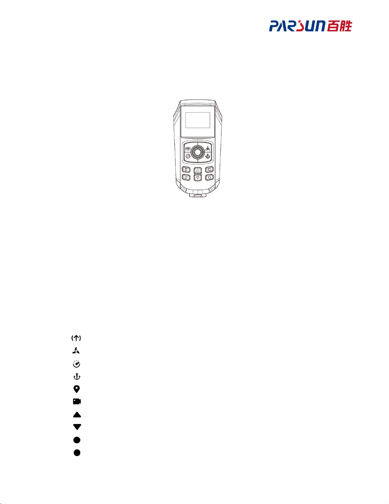
5.1 Appearance of the remote control .............................................................................. 28

6
5.2 Functional description of remote joysticks and buttons ............................................. 28
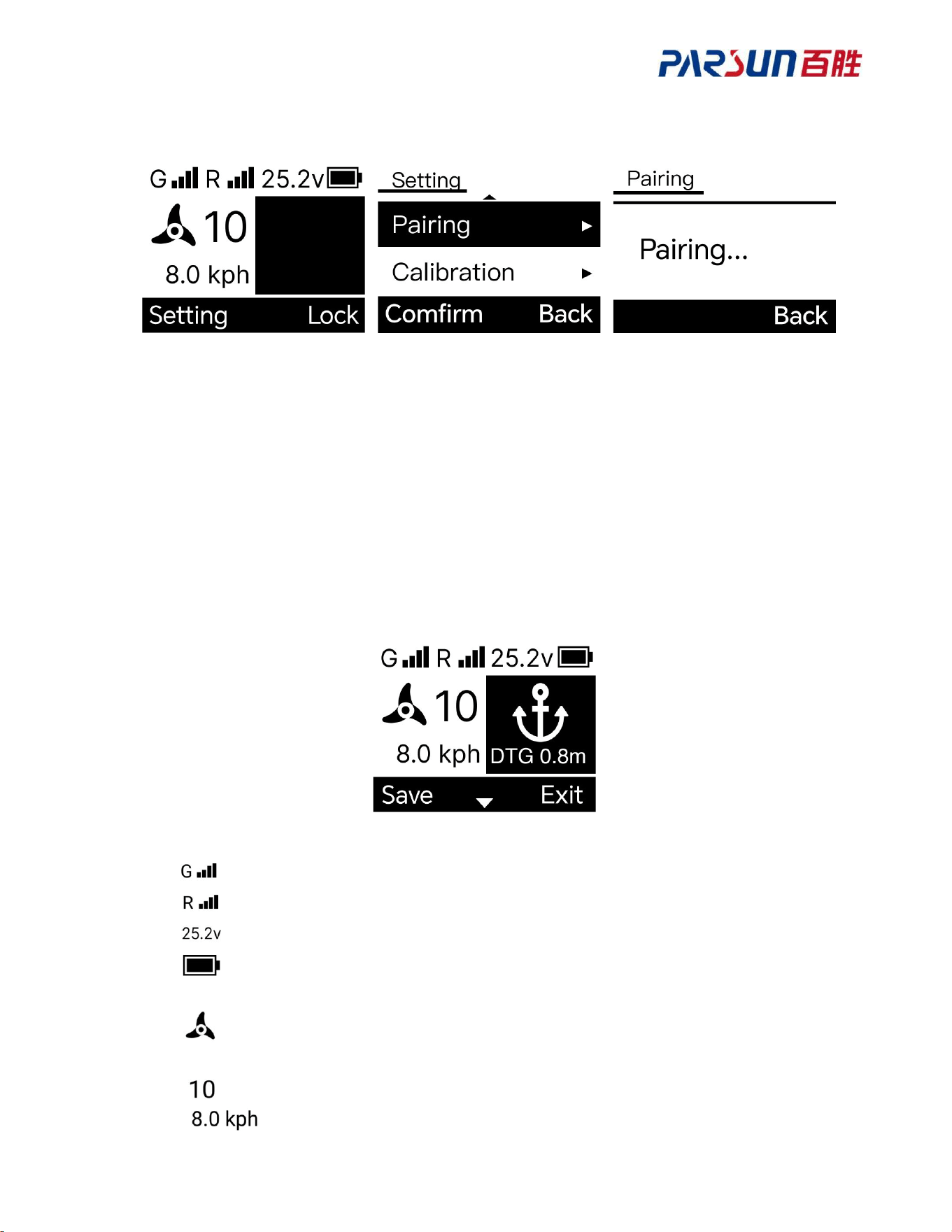
5.3 Pairing of remote control and unit ............................................................................. 29
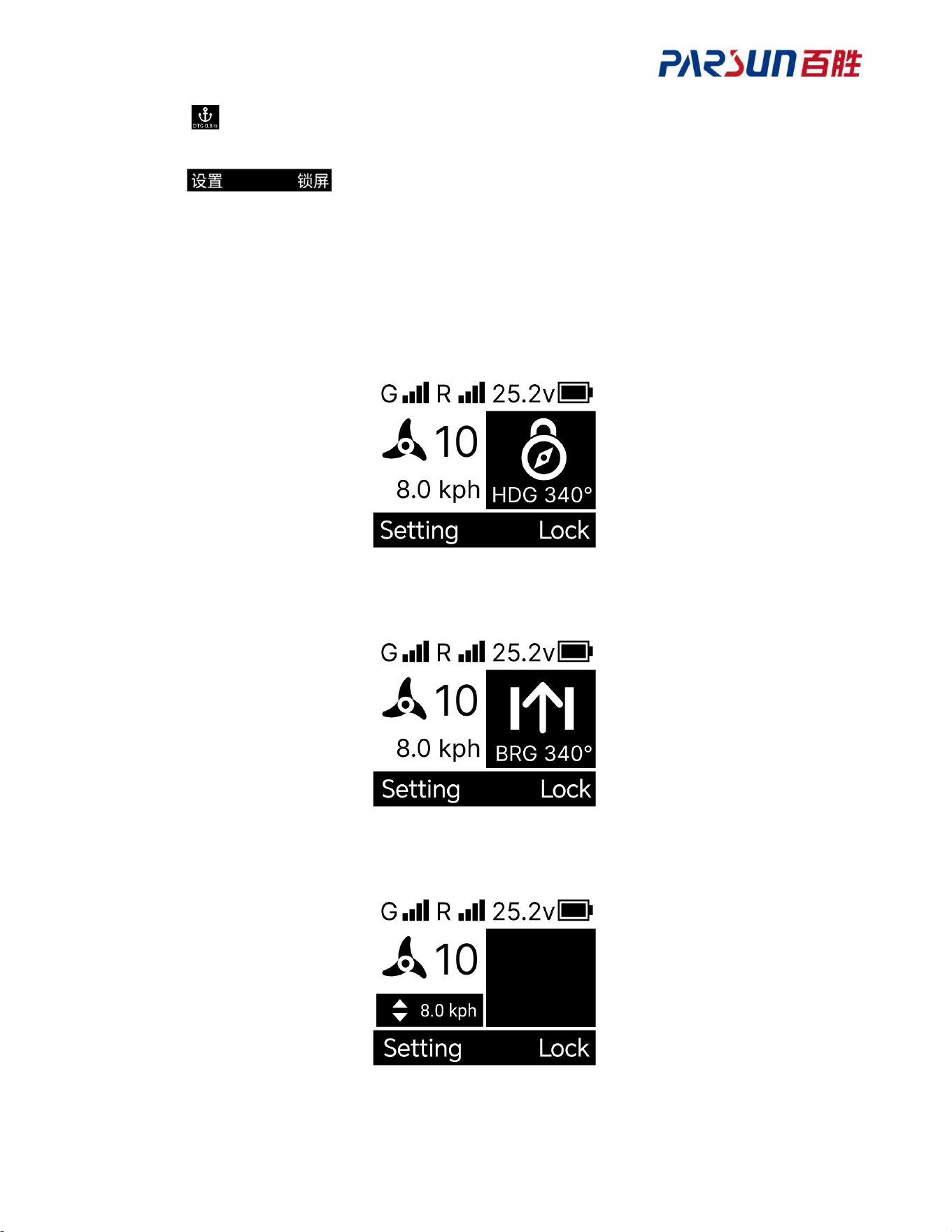
5.4 Description of remote control screen display ............................................................. 29
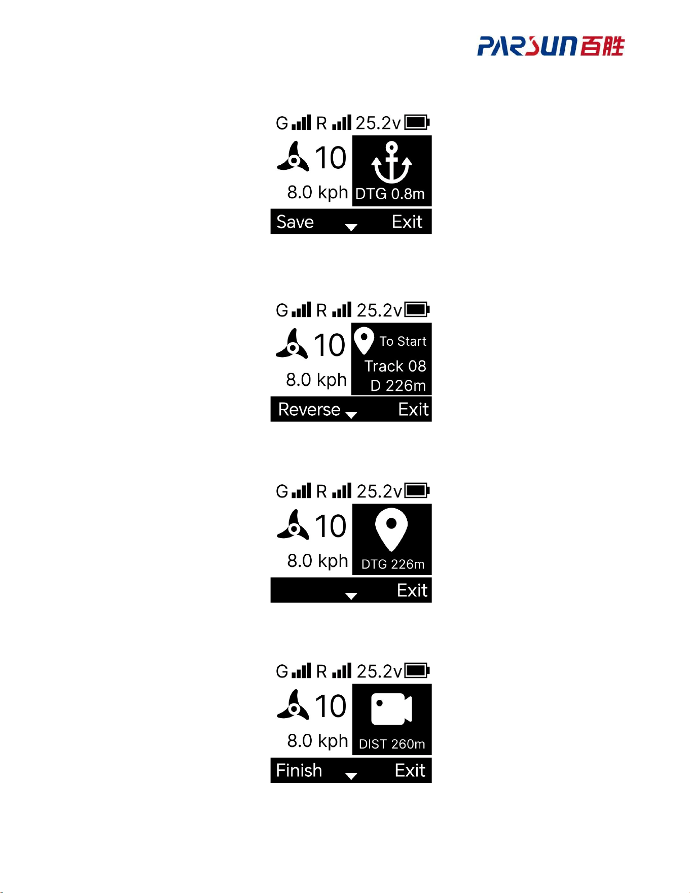
5.5 Screen display under different modes ........................................................................ 30
5.6 Unit working mode .................................................................................................... 34
5.6.1 Bow hold mode ............................................................................................... 34
5.6.2 Heading hold mode ......................................................................................... 35
5.6.3 Cruise mode .................................................................................................... 36
5.6.4 Anchoring mode .............................................................................................. 36
5.6.5 Navigation mode ............................................................................................. 37
5.6.6 GoTo mode ..................................................................................................... 38
5.6.7 Record route mode .......................................................................................... 38
5.6.8 Anchoring shifting .......................................................................................... 39
5.7 Remote control setting ............................................................................................... 39
5.7.1 Calibration ...................................................................................................... 39
5.7.2 Ship size .......................................................................................................... 39
5.7.3 Measuring unit ................................................................................................ 40
5.7.4 Language ......................................................................................................... 40
5.7.5 Backlight ......................................................................................................... 41
5.7.6 Auto shutdown ................................................................................................ 41
5.7.7 Propeller revolving speed ................................................................................ 41
5.8 Remote control charging ............................................................................................ 42
6 Fault Code and Prompt ......................................................................................................... 43
6.1 Unit indicator and buzzer ........................................................................................... 43
6.2 Heading sensor indicator ............................................................................................ 44
6.3 Remote control fault prompt ...................................................................................... 44
7 Maintenance ......................................................................................................................... 46
7.1 Routine maintenance .................................................................................................. 46
7.2 Maintenance schedule ................................................................................................ 46
7.3 Anode replacement .................................................................................................... 46
8 Warranty ............................................................................................................................... 47
8.1 Limited Warranty ....................................................................................................... 47
8.2 Exceptions ................................................................................................................. 48
8.3 Process for applying for warranty (claim) .................................................................. 48
7
1 Product Overview
1.1 Safety instructions
TM120B is used for marine propulsion systems and is powered by a battery, thus it is
inherently dangerous to some extent. Before using it, please carefully read the safety and
warning instructions in this manual. Failure to follow these instructions may result in personal
injury or machine damage.
1.1.1 Safety features
The following are the common safety features of TM120B.
Safety features Description
Overcurrent protection
When the current is too high, TM120B will stop running to
protect the motor.
Overtemperature
protection
When the temperature is too high, TM120B will automatically
reduce power to protect the motor.
Locked-rotor protection
If the propeller is entangled by debris, TM120B will stop
running to prevent damage.
Overvoltage protection
When the battery voltage is too high, TM120B will be
prohibited from starting.
Undervoltage protection
When the battery voltage is too low, the underwater unit will
be prohibited from starting.

8
1.1.2 Precautions
Battery
The rated voltage of TM120B is 24V and 12V respectively, and the max. current supported is
36A and 40A. If you are not using Parsun's standard battery, please select a battery according
to the following parameters.
When TM120B voltage is 24V, choose a battery with a voltage of 17-32V and a continuous
discharge current above 50A.
When TM120B voltage is 12V, choose a battery with a voltage of 10-18V and a continuous
discharge current above 50A.
If the voltage used is beyond the scope, TM120B may give out an alarm and produce fault and
irreparable damages.
Positioning accuracy
The precision of position holding may be affected by the following factors:
In the areas with shelters, such as valleys and bridges, or due to weather influence or if
satellite is just above TM120B, TM120B’s GPS signal may be instable.
Proximity to high-voltage lines, radar, or metal objects may cause magnetic interference.
Too high wind speed or too large or complex water current.
Low battery power, which results in reduced thrust.
Safety Precautions
Before use, ensure you are familiar with the basic operations, such as starting/stopping,
steering, retracting, and deploying.
Before use, please check the battery level.
Before use, ensure that the base screws are securely fastened.
When operating TM120B, do not apply excessive force to the foot pedal.
Do not use the automatic control function in areas with heavy boat traffic, narrow
waterways, poor visibility, or extreme sea conditions.
When folding or unfolding TM120B, do not place your fingers on moving parts.
After driving, disconnect TM120B from the battery.
After operation, stow the TM120B on the deck.
When connecting the battery, make sure the polarity is correct and the connection is
secure.

9
Keep the battery terminals clean and free of conductive materials.
After use in saltwater, clean the TM120B’s surface with fresh water.
Before installing or removing the propeller, ensure the TM120B has been powered off.
10
1.2 Packing list
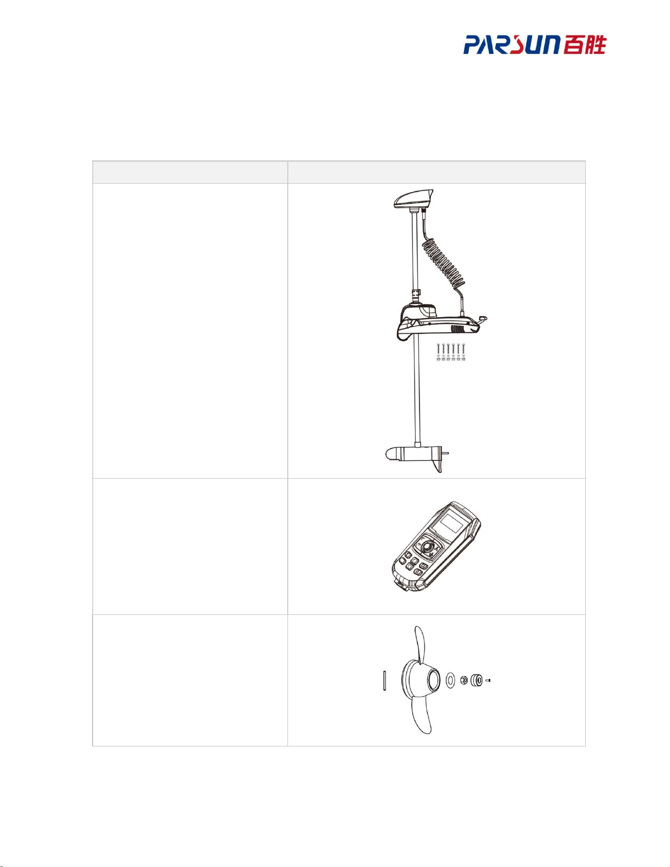
The items in TM120B package are as follows. After opening the package, please check if any
item is missing or damaged. If any, please contact your dealer.
Items Diagram
Unit x1
M8 Hex Socket Bolt x6
Flat Washer 8 x6
M8 Lock Nut x6
Remote Control x1
Φ4 Pin x1
Propeller x1
Flat Washer 10 x1
Lock Nut x1
Sacrificial Anode x1
M3*10 Hex Socket Bolt x1
11
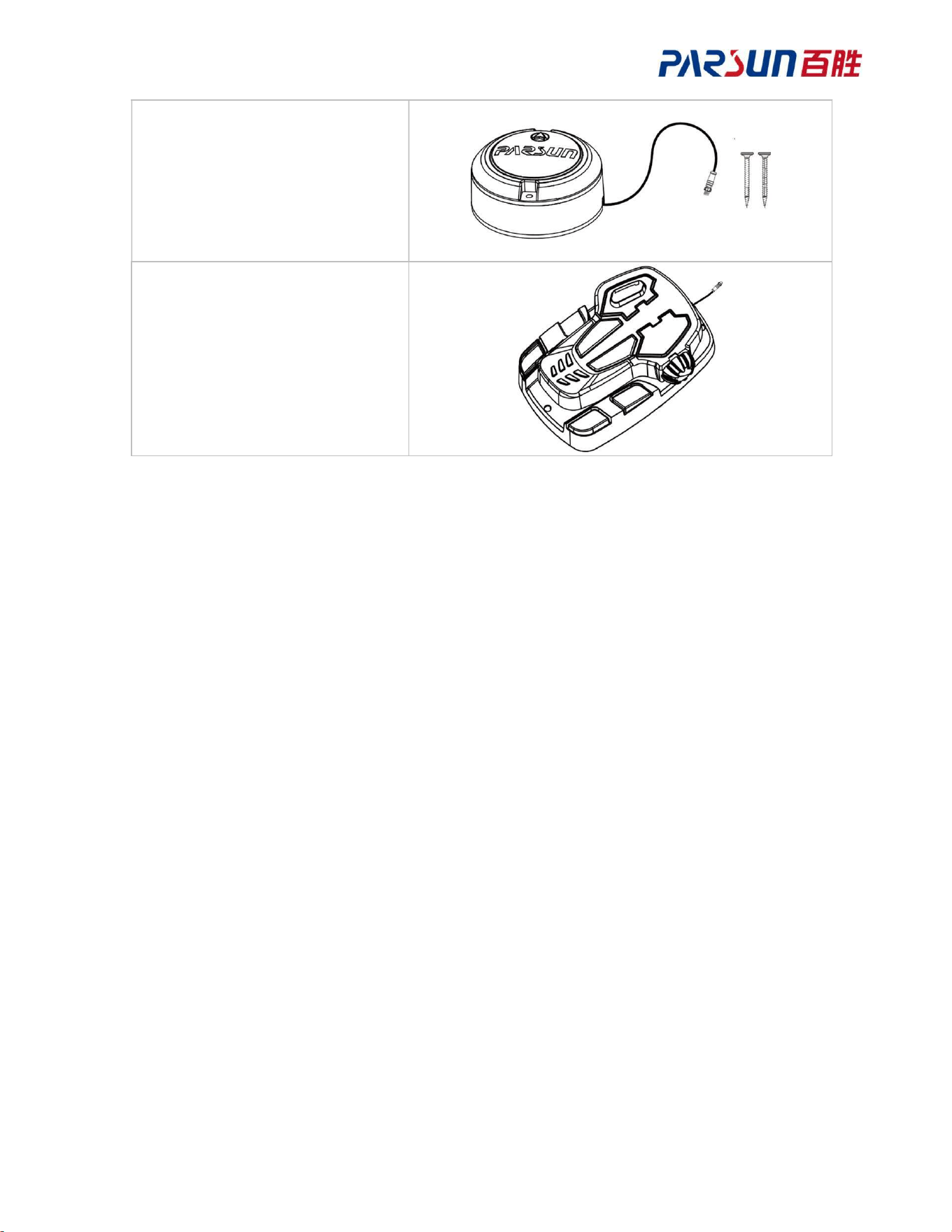
Heading Sensor x1
4.2*50 Self-tapping Screws x2
(optional)
Pedal x1
(optional)
12
1.3 Parts
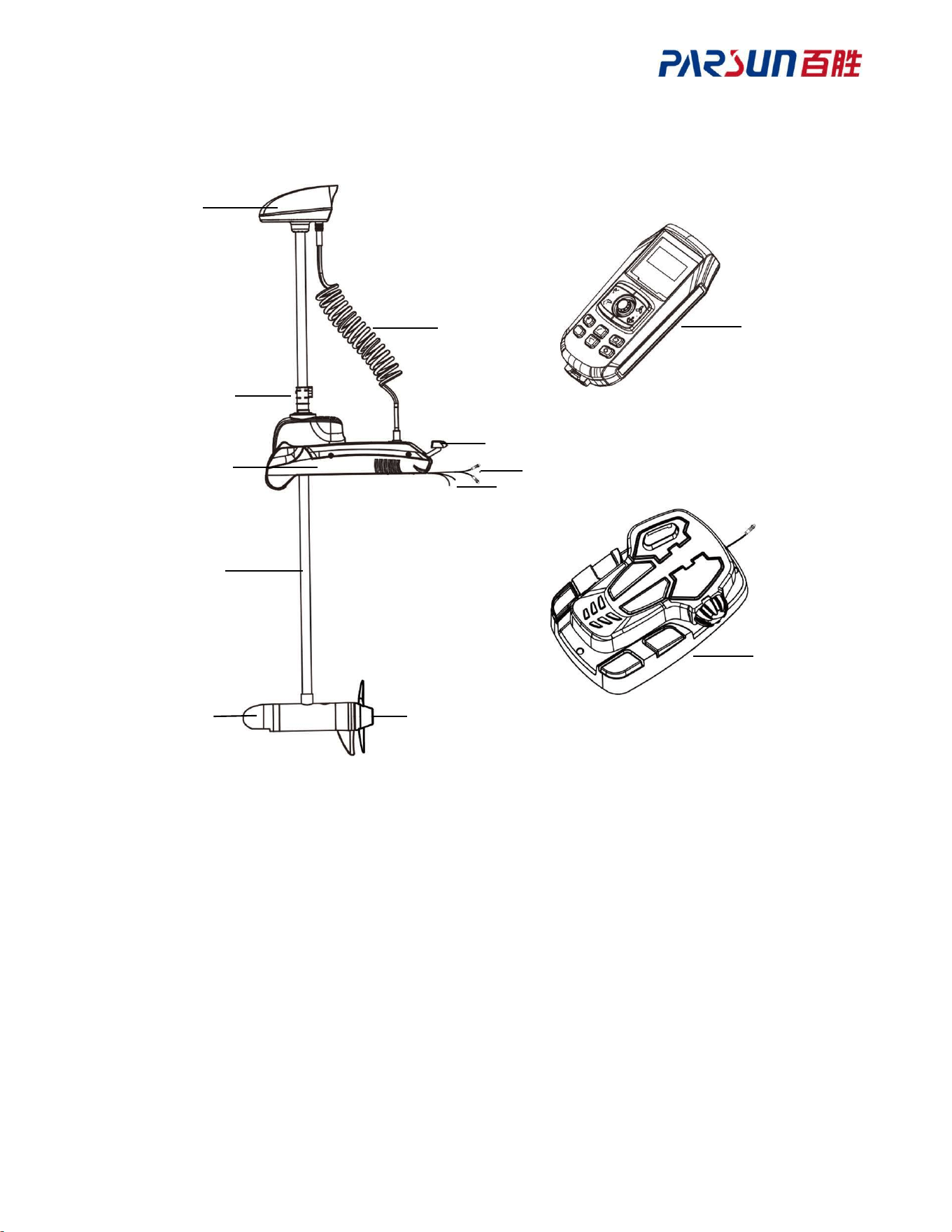
A GNSS Module
B Spring Harness
C Height Adjuster
D Retracting/deploying
Pedal
E Communication Harness
F Anode/Cathode Power
Supply Harness
G Base
H Main Rod
I Motor
J Propeller
K Remote Control
L Pedal
B
C
D
E
F
G
I
H
J
K
L
A
13
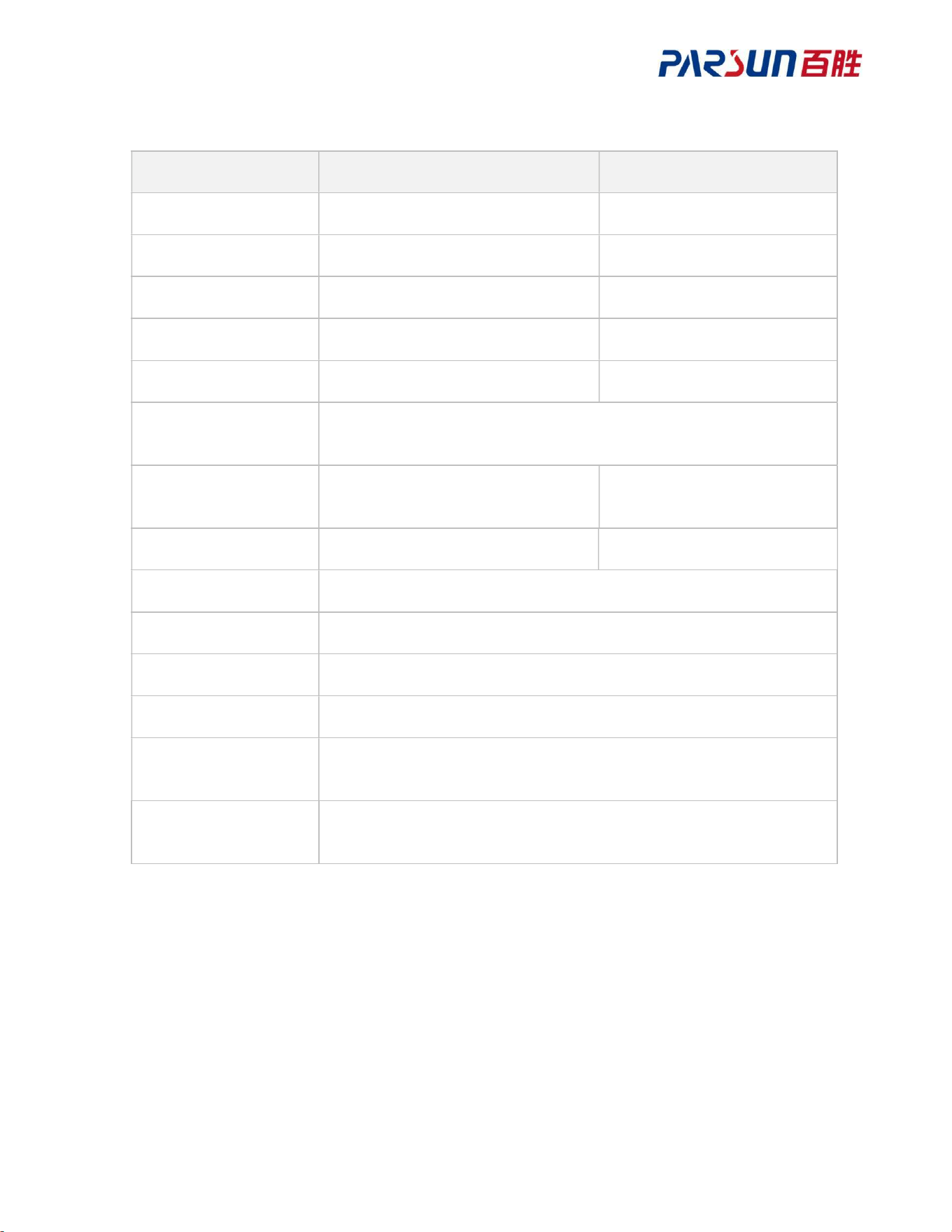
1.4 Specification
TM120-B 24V 12V
Rated voltage 24V 12V
Operating voltage 17-32V 10-18V
Max. thrust 90lb 55lb
Rated speed 1,900rpm 1,800rpm
Max. current 36A 40A
Propeller diameter/W
pitch
250 mm / 128 mm
Weight (excluding
pedals)
19.5kg 18kg
Shaft length 50”/65”/75”/85” 50”/65”
Speed Adjustable
Motor type DC brushed motor
Control method Pedal, remote control, APP
Lift mode Manual lift
Motor waterproof
rating
IP68
Overall waterproof
rating
IP66
14
1.5 Declaration of Conformity
Object of the Declaration
Product: Electric Outboard Motor
Model: TM120B-2450F, TM120B-2450S
TM120B-2465F, TM120B-2465S
TM120B-2475F, TM120B-2475S, TM120B-2485F, TM120B-2485S
TM120B-1250F, TM120B-1250S, TM120B-1265F, TM120B-1265S.
Company name: Suzhou Parsun Power Technology CO., LTD.
Address: 3rd Floor, BLD 2, Block 1, District 3. No.20 Datong Road, SND, Suzhou.·
JiangSu, China
This product is hereby declared to be in conformity with the following directives:
EMC Directive (Electromagnetic Compatibility Directive) 2014/30/EU
RoHS (Restriction of Hazardous Substances Directive) 2015/863/EU
RED Directive (Radio Equipment Directive) 2014/53/EU
FCC Part 15 (Title 47 of the Code of Federal Regulations, Part 15): This device must not cause
harmful interference and must accept any interference received.
Applicable Standards:
EN 55012:2007 EN 301489-1:2009
EN 303413:2007 EN 301489-17:2020
EN 50663:2017 EN 61000-6-1:2009
EN 301489-18:2022 EN 300328:2019
EN 301489-19:2019 EN 62479:2010
EN IEC 63000:2018
FCC Part 15 “Federal Communications Commission Rules, Part 15”: This device must not
cause harmful interference and must accept any interference received.
EU Conformity Statement
Hereby, PARSUN declares that the radio equipment type is in compliance with
Directive2014/53/EU.

15
RF Exposure Information
This device has been tested and meets applicable limits for Radio Frequency (RF) exposure.
Caution: The user is cautioned that changes or modifications not expressly approved by the
party responsible for compliance could void the user's authority to operate the equipment. This
device complies with Part 15 of the FCC Rules. Operation is subject to the following two
conditions: (1) this device may not cause harmful interference, and (2) this device must accept
any interference received, including interference that may cause undesired operation. NOTE:
This equipment has been tested and found to comply with the limits for a Class B digital
device, pursuant to Part 15 of the FCC Rules. These limits are designed to provide reasonable
protection against harmful interference in a residential installation. This equipment generates,
uses and can radiate radio frequency energy and, if not installed and used in accordance with
the instructions, may cause harmful interference to radio communications. However, there is
no guarantee that interference will not occur in a particular installation. If this equipment does
cause harmful interference to radio or television reception, which can be determined by turning
the equipment off and on, the user is encouraged to try to correct the interference by one or
more of the following measures:
-- Reorient or relocate the receiving antenna.
-- Increase the separation between the equipment and receiver.
-- Connect the equipment into an outlet on a circuit different from that to which the receiver is
connected.
-- Consult the dealer or an experienced radio/TV technician for help.
FCC Radiation Exposure Statement:
This equipment complies with FCC radiation exposure limits set forth for an uncontrolled
environment. This transmitter must not be co-located or operating in conjunction with any
other antenna or transmitter.
RF Parameters
1.RF Function: Bluetooth Low Energy (BLE) Wireless Data Transmission
- Frequency Band: 2402 MHz - 2480 MHz
- Transmitter Power: ≤ 0.68 dBm (For remote control)
- ≤ -7.52 dBm (For Trolling Motor)
16
B
40mm
2 Installation
2.1 Install the unit
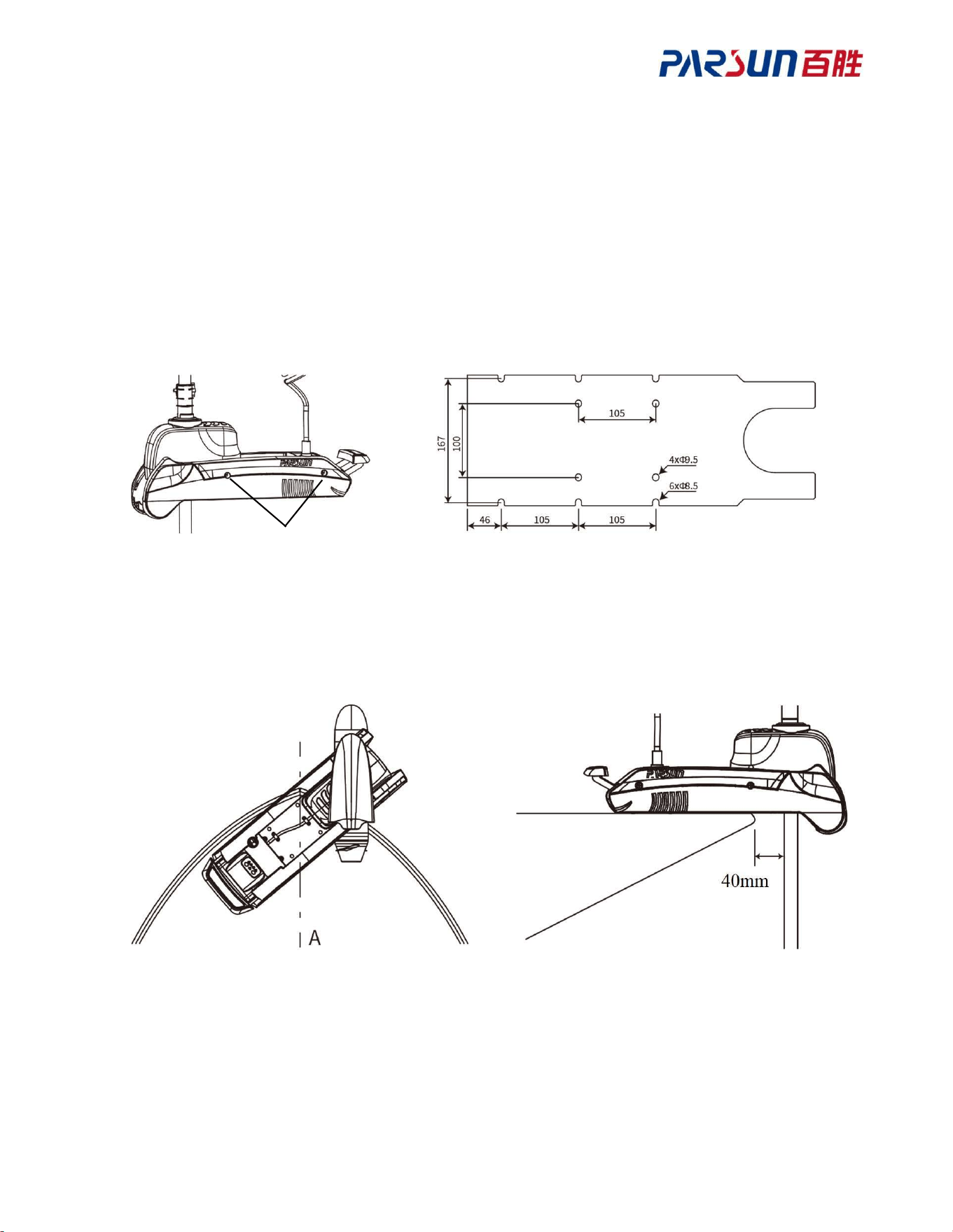
Step 1: Take off the right and left coverplates (A) on both sides through the mounting holes on
the base and six mounting holes (B) will appear; after the unit is retracted, the four mounting
holes (C) at the middle of base will be seen; TM120B can be retracted and deployed by
referring to Chapter 3.1“Machine Retraction and Deploying”.
Step 2: Place TM120B on the ship's deck, align the shaft as close as possible to the ship's keel
(A). For installation, it is recommended to use 6 screws; otherwise, use at least 4.
During installation, leave a gap of at least 40 mm between the shaft and the upper edge of the
ship’s gunwale or front segment of extension bracket.
(Deck mounting mode)
A
C
17
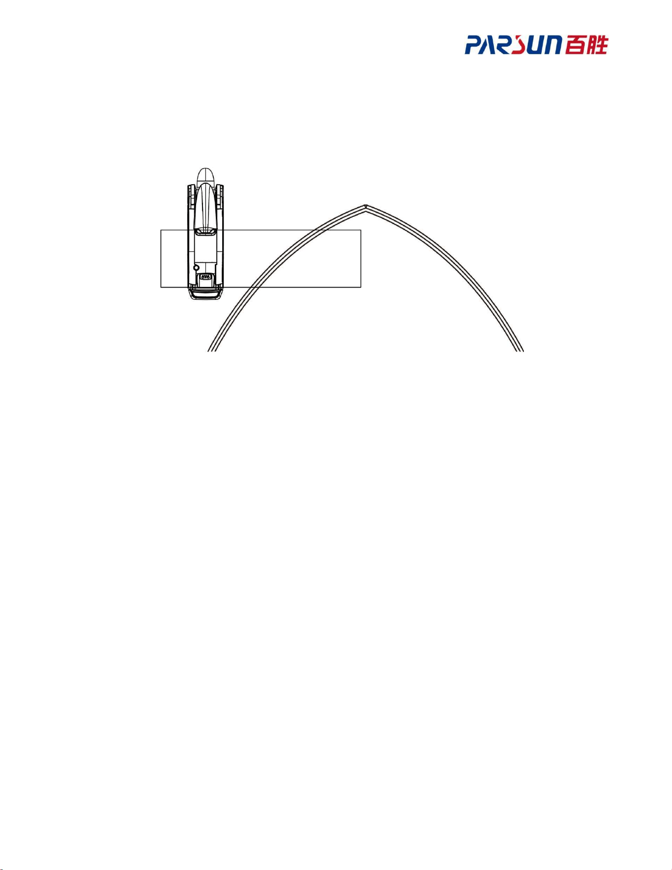
If TM120B can't be mounted on the deck, mount it outboard by fixing an extension board on
the boat deck before fixing TM120B onto the extension board.
Note: Ensure that the extension board has enough strength to prevent crack of extension board
and falling of machine into water.
(Outboard mounting mode)
18
A
2.2 Install the propeller
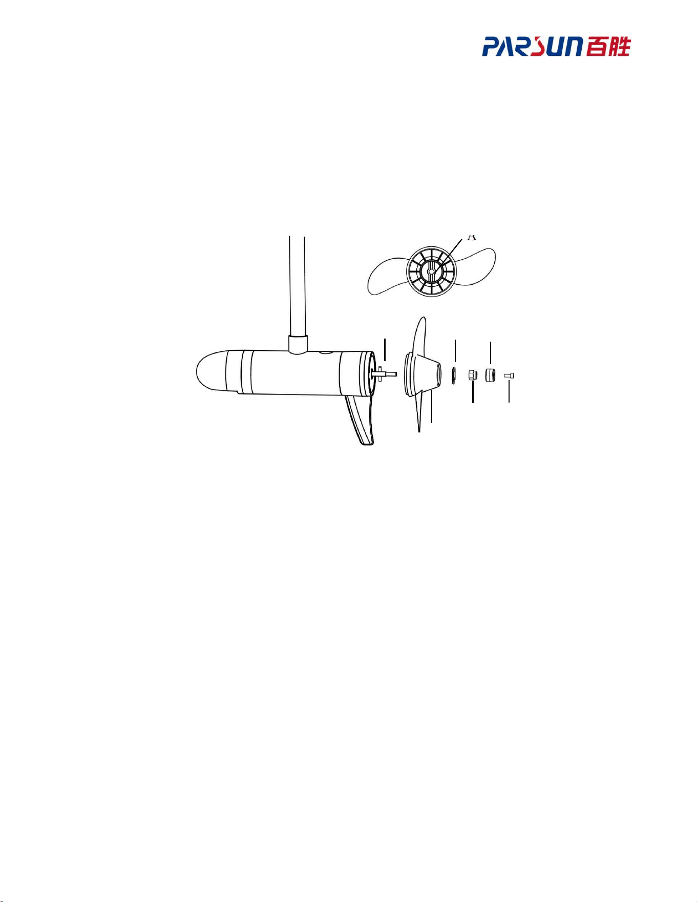
Insert pin (B) onto the motor shaft, then align the slot (A) of the propeller with the pin and
install it onto the motor shaft. Install the propeller (C), washer (D), locknut (E), anode (F), and
screw (G) in sequence.
Note: Ensure the correct installation sequence and fasten the propellers, to prevent running
faults of machine or personal injury.
2.3 Install the pedals (optional) and heading sensor (optional)
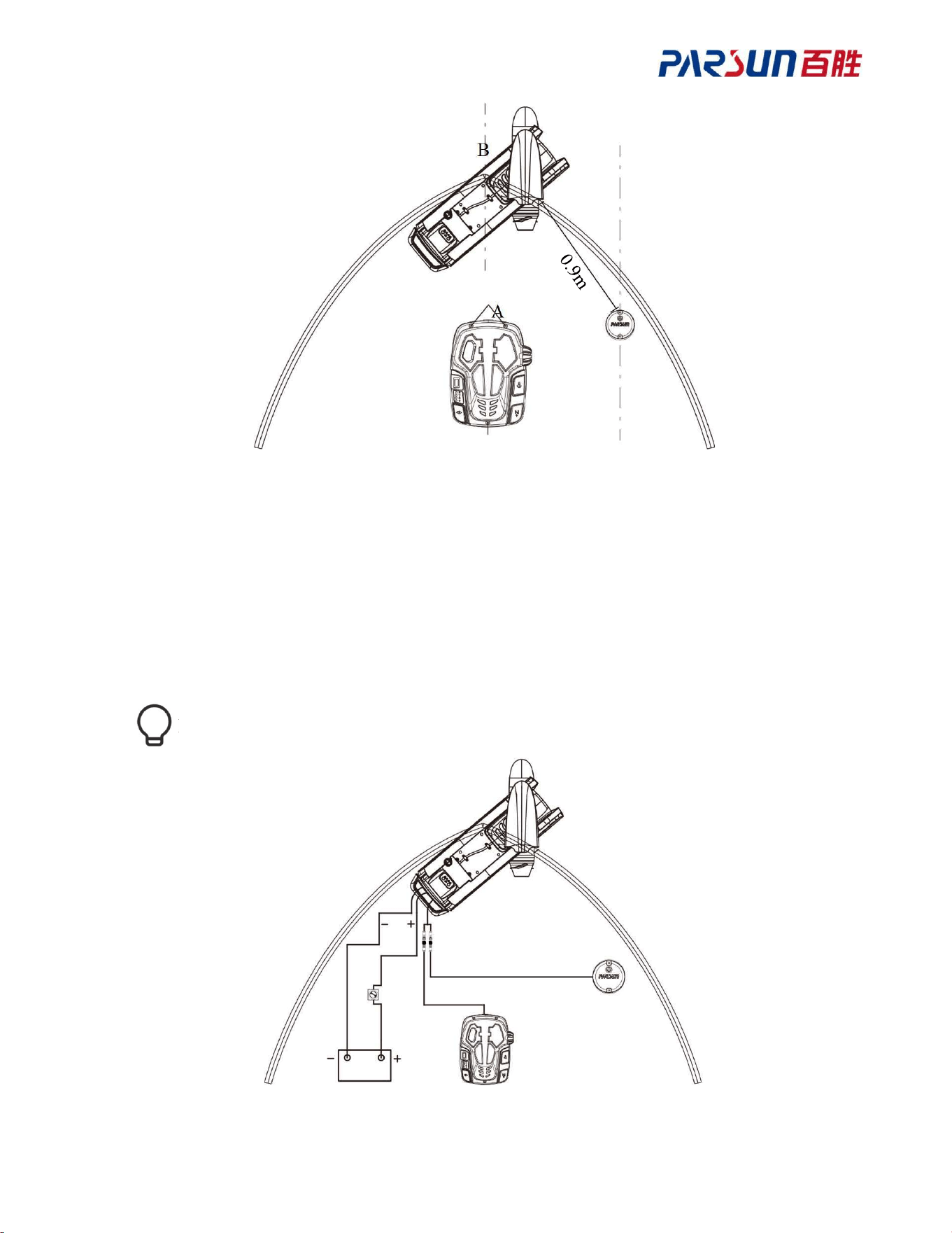
On the foot pedal there are three holes (A), which can be used to secure the machine to the
deck of the boat. Fix it onto the deck to prevent the foot pedal from moving.
The heading sensor should be installed horizontally, with the arrow pointing forward and
aligned parallel to the keel (B) of the boat; it is recommended to install it close to the keel.
The heading sensor should be installed as far away from unit as possible, at least 0.9m (1 foot),
to avoid magnetic field interference.
The heading sensor should be installed as far away from the power cable and other electronic
equipment, to avoid magnetic field interference on the working effects of heading sensor.
B
C
D
E
F
G
19
A
A
B
2.4 Connect wiring harness
Connect the red power cable from the unit to the anode of battery, and the black power cable to
the cathode of battery. Connect the harness of pedal and heading sensor to the communication
line of the unit respectively.
It is recommended to add a switch in the middle of the wiring harness.
20
A
3 Unit
3.1 Fold and unfold TM120B
Unfold
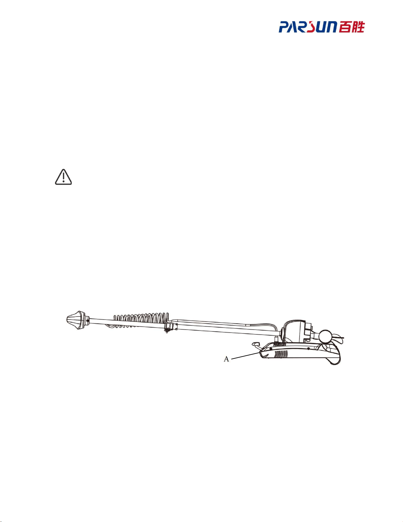
Step 1: Press the retracting/deploying pedal (A), hold the main rod, and push it to the limit
position of the base.
Step 2: Push the main rod forward and upwards, until it is vertical to the base.
Step 3: Release the retracting/deploying pedal (A).
Ensure TM120B is locked completely when unfolding it.
Fold
Step 1: Press the retracting/deploying pedal (A), press the main rod until it is parallel to the
unit and base, and then pull the unit to the back.
Step 2: Rotate the motor until it is parallel to the base.
Step 3: Pull the unit back to the end, and then release the retracting/deploying pedal (A).
21
3.2 Adjust height
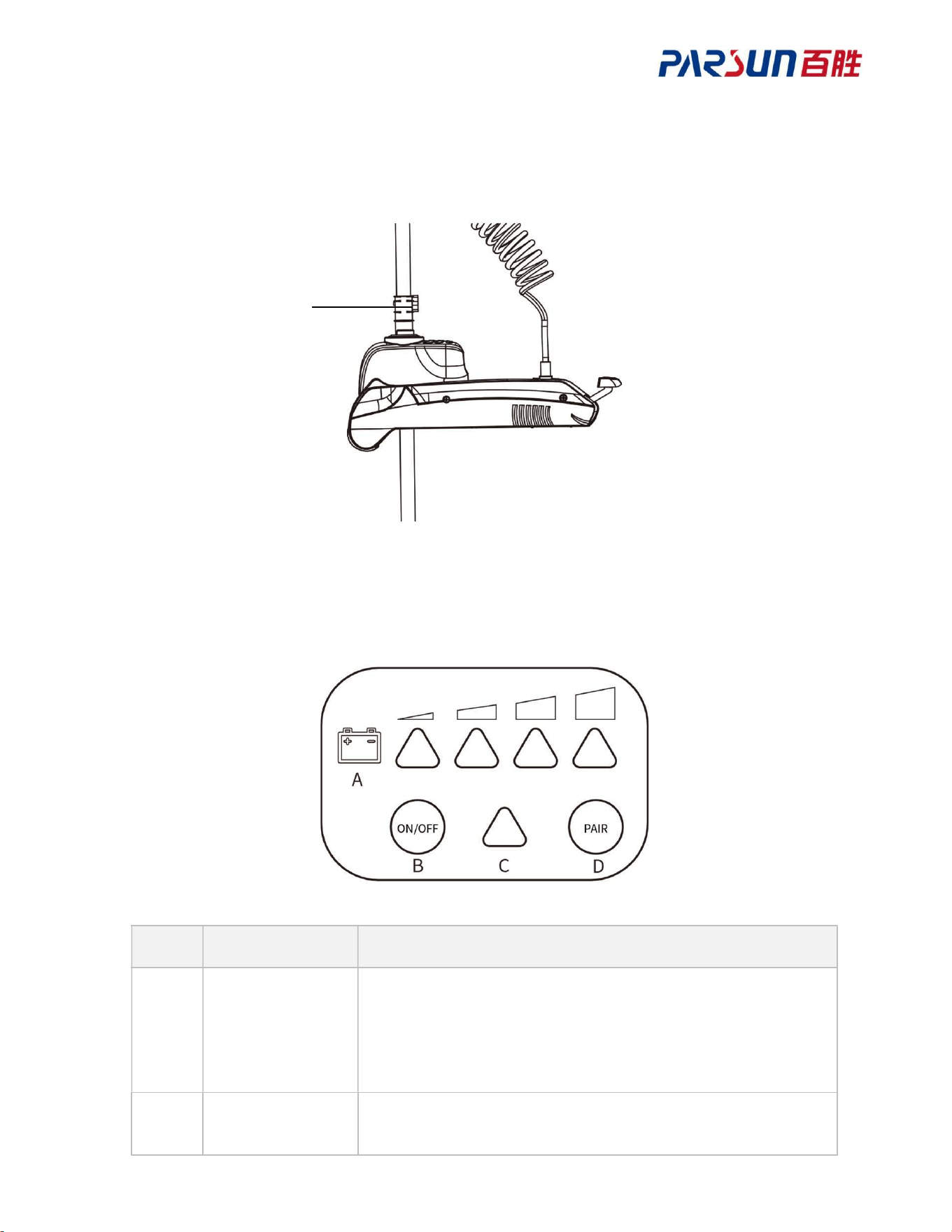
Loosen the height adjuster (A), then move TM120B up or down to the desired position, and re-
tighten the height adjuster (A).
3.3 Panel
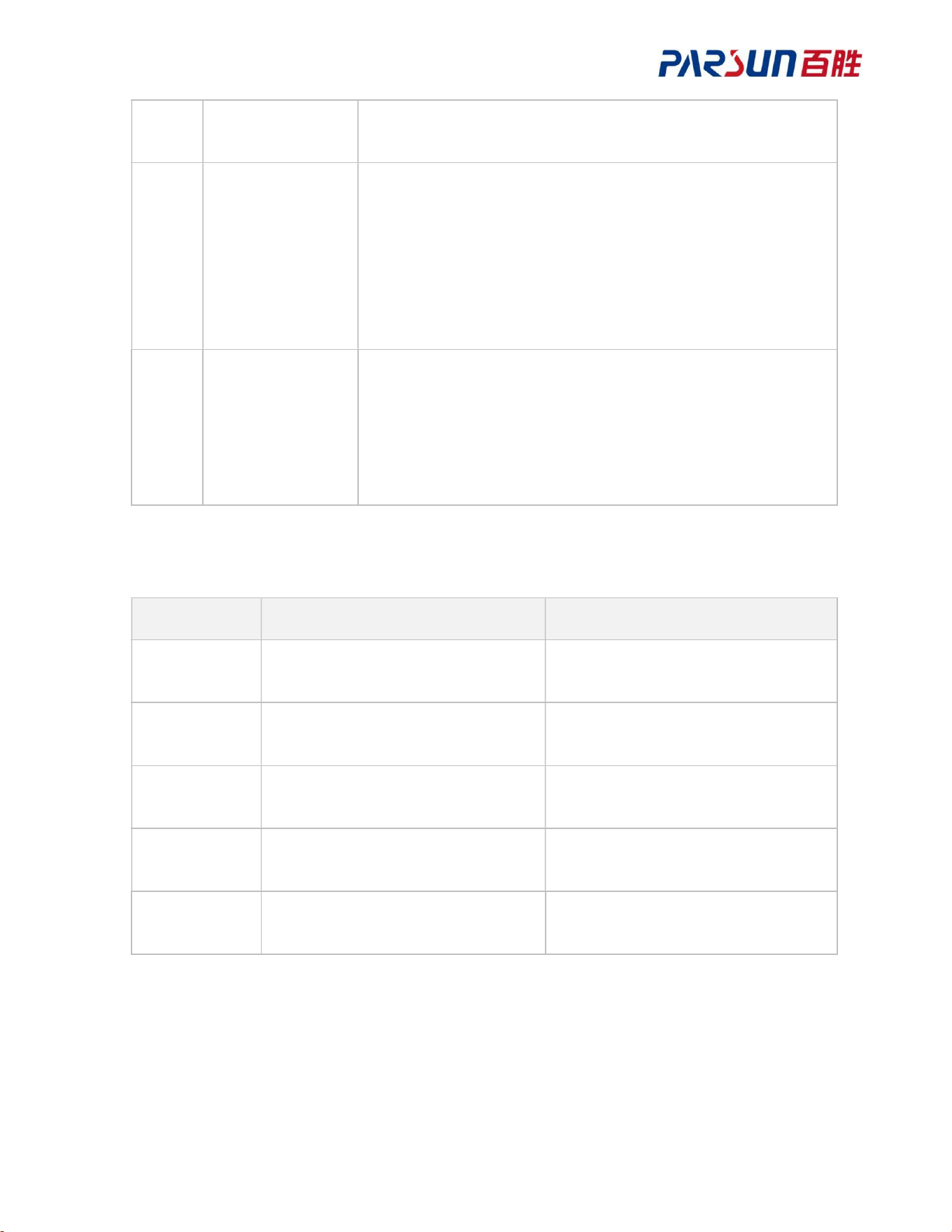
No. Function Description
A On/Off indicator
Green indicator is normally on or flickers
On/Off indicator has 4 bars in total, the battery level
increases from the left to the right; see 3.3.1 “On/Off
indicator” for details.
B On/Off button
When TM120B is powered off, press this button to power it
on.
A
22
When TM120B is powered on, press and hold it for 3s to
power it off.
C Status indicator
Starting: White.
Idle (GPS not located): Yellow.
Idle (GPS located): Green.
Running (motor started): Blue.
Alarm: Yellow.
Error: Red.
D
Pairing/anchoring
button
Press and hold this button for 2s, and the unit will beep for 3
times to enter the pairing mode; meanwhile, the remote
control can also enter pairing mode to complete pairing.
Press this button to start anchoring mode of the unit, and then
press it again to quit anchoring mode.
3.3.1 Power level indicator
Indicator TM120B-24V TM120V-12V
1 bar
flickering
<22.2V <11.5V
1 bar
normally on
22.2 V~23.0V 11.5 V~11.9V
2 bars
normally on
23.0 V~23.8V 11.9 V~12.2V
3 bars
normally on
23.8 V~24.6V 12.2 V~12.5V
4 bars
normally on
>24.6V >12.5V
23
3.4 Anti-tangling of spring wire
When spring wire is tangled for over 1 circle under non-manual mode, it will trigger anti-
tangling and the motor will be powered off temporarily, the ship controller will rotate
automatically to untangle, and then return to the angle that triggers anti-tangling; then, the
motor will be powered on automatically.
When the spring wire is winded for over 1 circle under manual mode, it will trigger limit
protection and the motor can't rotate anymore.
Ensure that the spring wire is not tangled when the unit is powered on, so that anti-
tangling protection can become effective normally.
24
A
B
4 Pedal
4.1 Steering
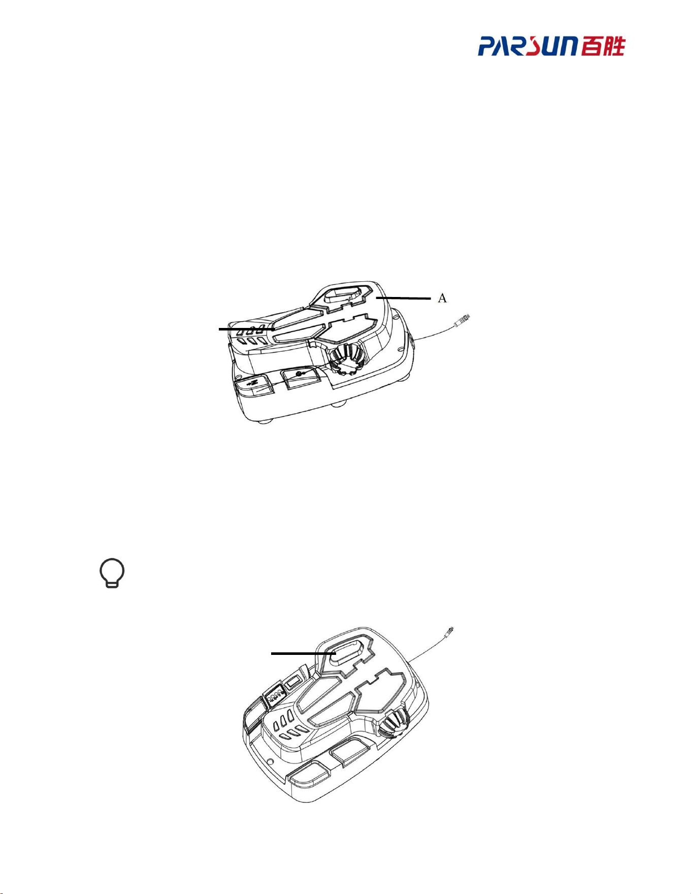
Press down the front end (A) of the pedal to turn the boat to starboard; when it is fully pressed,
TM120B turns 180° to the right.
Press down the rear end (B) of the pedal to turn the boat to port; when it is fully pressed,
TM120B turns 180° to the left.
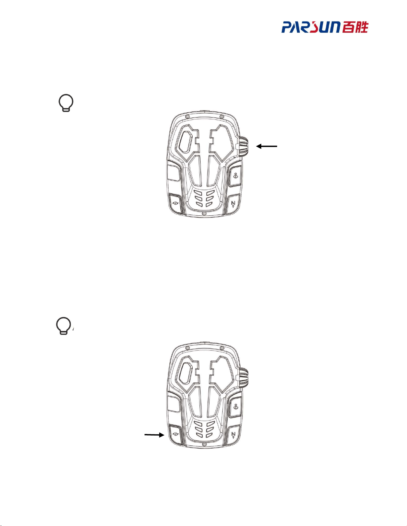
4.2 Momentary switch
After pressing the momentary switch (A), the propeller will operate (premise: the speed
control knob is not in the OFF position). When the momentary switch is released, the propeller
will stop.
When TM120B is in the retracted position, propeller running is prohibited; do not
operate the propeller when it is not underwater.
A
25
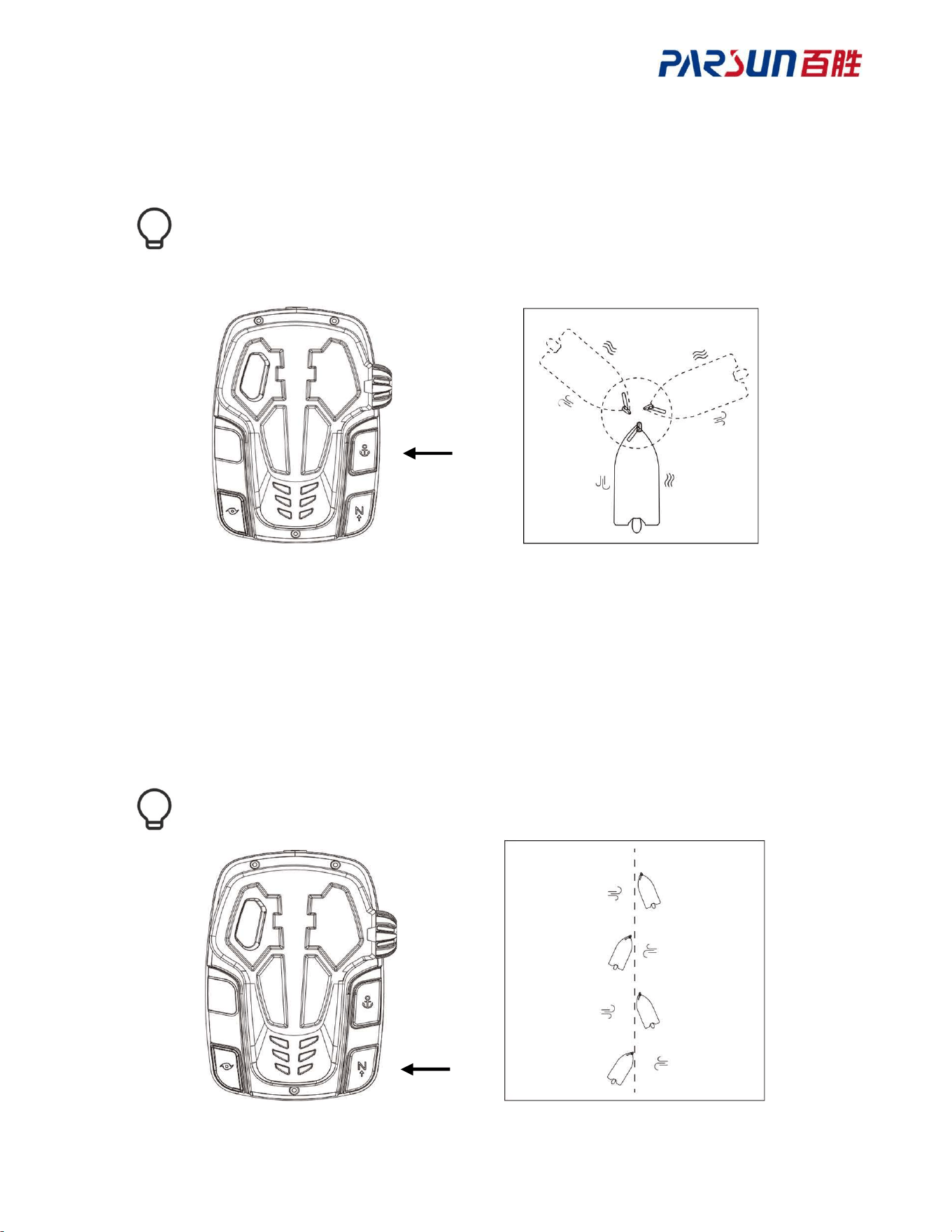
4.3 Level adjustment
Rotate the level adjustment knob to change the settings of TM120B; there are a total of 10
levels, and there is no active setting when it is in the OFF position.
The levels are not linear.
4.4 Continuous switch
After pressing the continuous operation switch, if the speed adjustment knob is not in the OFF
position, the propeller will keep running. Press the continuous operation switch again to stop
the propeller. Under continuous mode, you can change the steering direction through the pedal.
After pressing the momentary switch and any function, the function will be disabled.
26
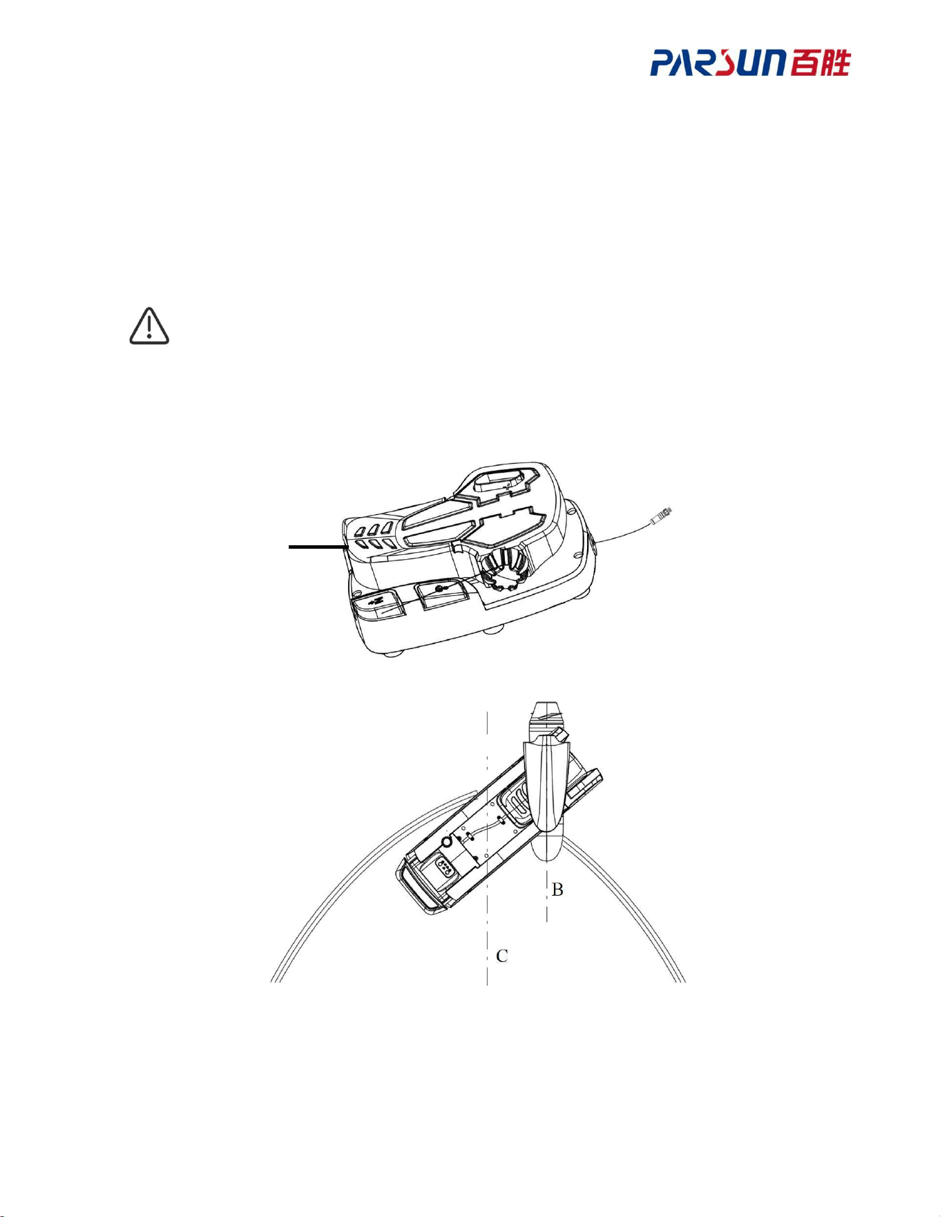
4.5 Anchoring (electronic anchor)
Keep the boat in its current position.
Any pedal operation will stop this function.
In this mode, the course of the boat will be affected by wind or current.
4.6 Bow/heading hold
TM120B will plot an invisible route in the direction indicated by the heading. During this
period, the boat will automatically follow the route, and the speed can be adjusted using the
control knob. Under bow/heading hold mode, the steering direction can be changed through
the remote control, the boat will replan its route along with the adjusted direction, and sail
along with the new route.
This function will stop after triggering other modes.
27
A
B
C
4.7 Steering calibration
1.Adjust the foot pedal to the maximum backward tilt (A)
2.Rotate the left joystick of remote control to rotate the unit anticlockwise for 180° relatively
to the keel, so that its head (B) of machine is parallel to the keel line of the boat (C) and the
head points towards the stern of the boat.
3.Conduct calibration on the “Remote control calibration” - “Keel calibration page”.
Be sure to perform this operation the first time you use the TM120B, as it will affect
the steering control.
When there's major deviation between headset and pedal control direction,
please calibrate the steering direction again.
28
5 Remote Control
5.1 Appearance of the remote control
5.2 Functional description of remote joysticks and buttons
Joystick:
Push up: Push up to increase the main motor level by 1; push up continuously to increase
the main motor level continuously.
Push down: Push down to decrease the main motor level by 1; push down continuously to
decrease the main motor level continuously.
Push left: Rotate the unit to the left.
Push right: Rotate the unit to the right.
Press button:
Bow/heading hold mode on/off button.
Main motor on/off button.
Cruise mode on/off button.
Anchoring mode on/off button.
Buttons of navigation function menu.
Route record mode on button.
Menu up button.
Menu down button.
Left mapping button of left menu, press and hold it to turn on/off the remote control.
Right mapping button of right menu.
29
5.3 Pairing of remote control and unit
1. Press the “Up” or “Down” button of remote menu on the homepage, switch the bottom
menu bar of screen to display “Setting” on the left side, and display “Lock screen” menu bar
on the right side.
2. Press the left selection button of the menu to enter setting page. Press the “Up” or “Down”
button to switch and select the “Pairing” menu, press the “Menu left selection” button and
select “Pairing” to enter the pairing page; remain on this page, and then press the “Pairing”
button on the unit control panel; pairing will succeed when you hear 5 beeps in succession.
5.4 Description of remote control screen display
Top status bar:
GNSS system signal
Remote control signal
Voltage of unit battery
Remote control power level
Middle operation status bar:
Main motor rotation status of unit: The blade rotation speed increases along with
level increase, or blades will stop when motor level is 0 or when motor is powered off.
The main motor level of unit can be adjusted within Level 0-10.
Current drive speed of the unit.
30
Current mode of the unit.
Bottom menu bar:
Setting: Press the left “Mapping” of the menu to enter the setting page.
Screen lock: Press and hold the “Lock” button of remote control.
5.5 Screen display under different modes
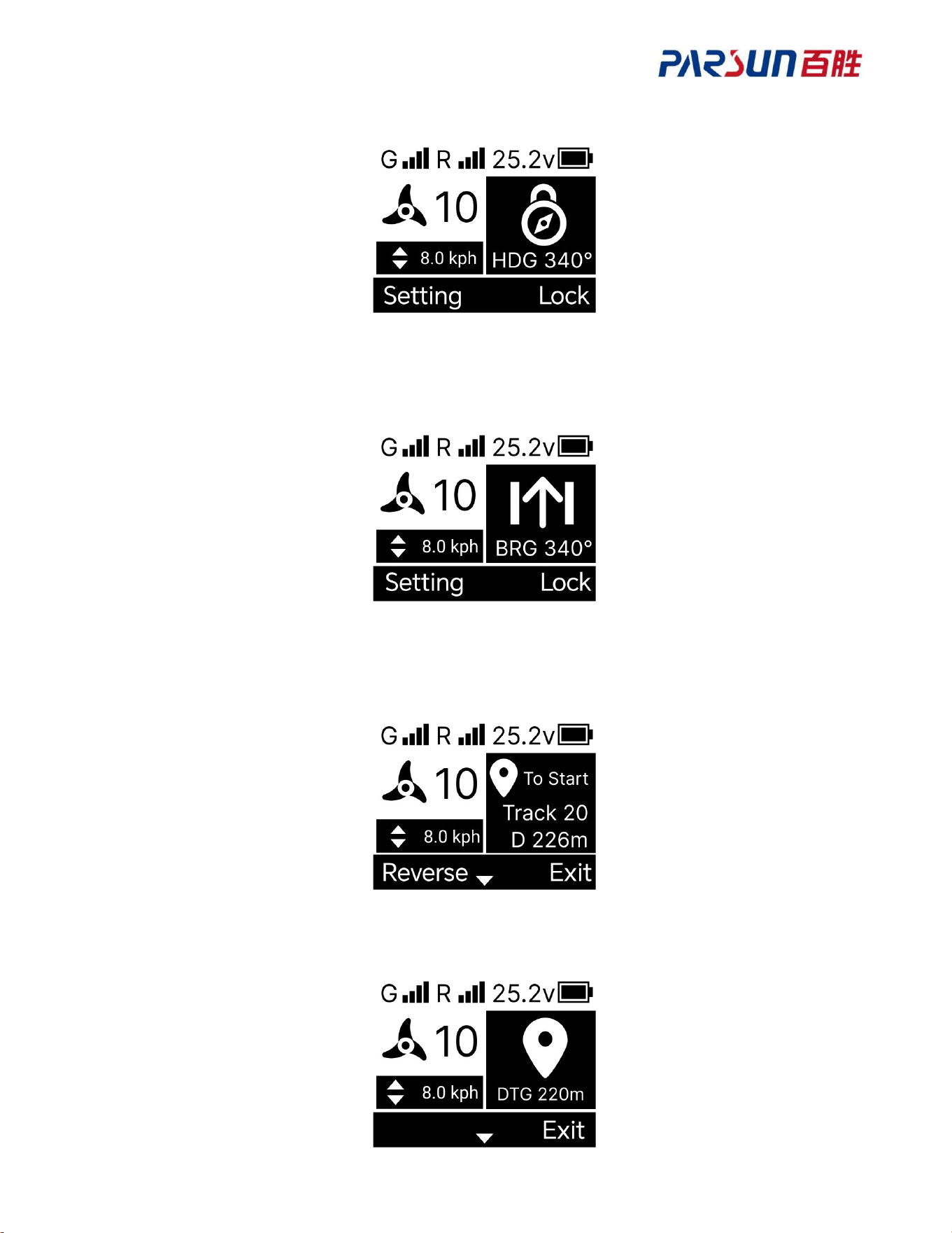
● Bow hold mode
The bow direction is consistent with HDG value.
● Heading hold mode
The unit drives in a straight line, and the direction is consistent with BRG value.
● Cruise mode
The unit drive speed is close to the target speed.
31
● Anchoring mode
DTG is the distance to the anchoring point.
● Navigation mode
Track is the serial number in route menu, D is the remaining distance to the start point of route.
● GoTo mode
DTG is the remaining length and distance to the destination.
● Record route mode
DIST is the recorded route distance.
32
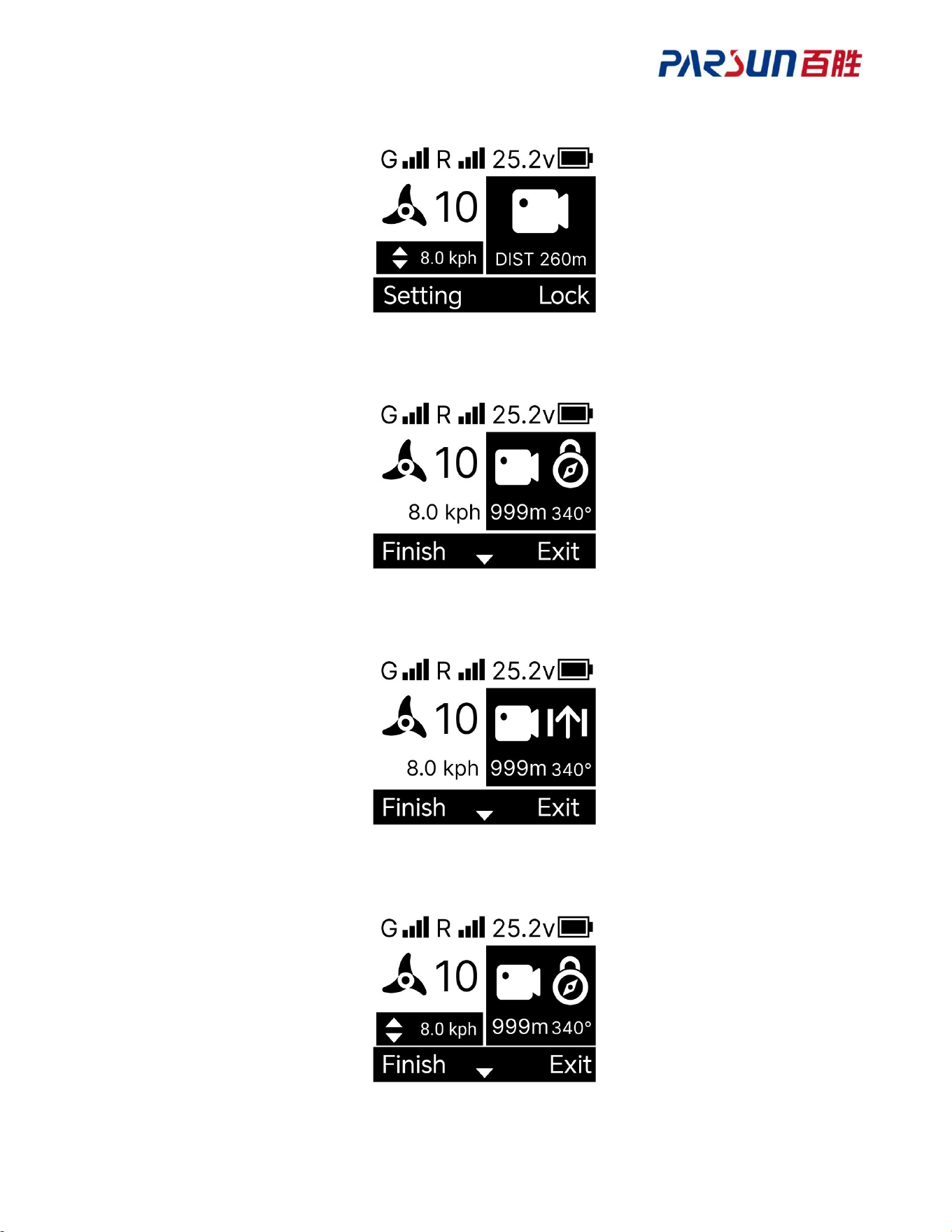
● Enable [Cruise mode] & [Bow hold mode] at the same time
● Enable [Cruise mode] & [Heading hold mode] at the same time
● Enable [Cruise mode] & [Navigation mode] at the same time
● Enable [Cruise mode] & [GoTo mode] at the same time
33
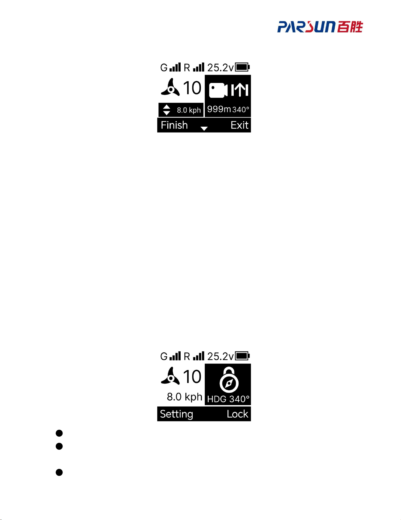
● Enable [Cruise mode] & [Record route mode] at the same time
● Enable [Record route mode] & [Bow hold mode] at the same time
● Enable [Record route mode] & [Heading hole mode] at the same time
● Enable [Record route mode] & [Cruise mode] & [Bow hold mode] at the same time
34
● Enable [Record route mode] & [Cruise mode] & [Heading hold mode] at the same time
5.6 Unit working mode
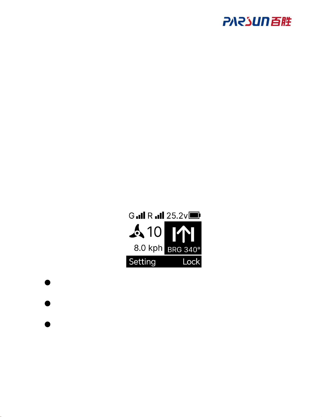
5.6.1 Bow hold mode
Firstly, set the function of “bow/heading hold” button of the remote control as “bow hold
mode”.
1. Press the Up” or “Down”“Up” or “Down” button of the remote control on the homepage to
switch the screen bottom menu, show the setting menu bar on the left side and show screen
lock on the right side.
2. Press the “Select left” button to enter the setting page.
3. Press the “Up” or “Down” button to search the hold mode menu, press the “Select left”
button to select “Hold mode” and enter the hold mode setting page.
4. Press the “Up” or “Down” button to select “Heading hold”, then press the “Select left”
button to save the settings.
Then, press the “Bow/heading hold” button of remote control under [Manual mode], [Cruise
mode] and [Record route mode], to trigger [Bow hold mode].
After this mode is enabled, the unit will move along with the direction of its bow.
This mode can be enabled under [Manual mode], [Cruise mode] and [Record route
mode], all of which can be enabled with this mode.
Press the “Bow/heading hold” button of remote control again to exit [Bow hold mode].
35
Change bow direction
Press the “Motor left rotation” & “Motor right rotation” buttons under [Bow hold mode] to
change the bow direction of unit.
5.6.2 Heading hold mode
Firstly, enable “Heading hold mode” through the “Bow/heading hold” button of the remote
control
1. Press the ““Up” or “Down” button” button of remote control on the homepage to switch the
screen bottom menu, show the setting menu bar on the left side and show screen lock on the
right side.
2. Press the “Select left” button to enter the setting page.
3. Press the “Up” or “Down” button to search the hold mode menu, press the “Select left”
button to select “Hold mode” and enter the hold mode setting page.
4. Press the “Up” or “Down” button of menu to select “Heading hold”, then press the “Select
left” button to save the settings.
press the “Heading/bow hold on/off” button of remote control to enable [Heading hold mode].
After this mode is enabled, the unit will enter straight line driving along with the current
bow hold direction.
This mode can be enabled under [Manual mode], [Cruise mode] and [Record route
mode], all of which can be enabled with this mode.
Press the “Bow/heading hold” button again to exit [Bow hold mode].
Change heading direction
Press the “Push left” or “Push right” button of remote control joystick under [Heading hold
mode] to change the straight line drive direction of unit.
36
5.6.3 Cruise mode
Press the “Cruise on/off” button of remote control to enable [Cruise mode].
After this mode is enabled, the unit will drive along with the current speed, and set the
current speed as the target speed.
This mode can be enabled under [Bow hold mode], [Heading hold mode], [Record route
mode], [Route mode] and [GoTo mode], all of which can be enabled with this mode.
Press the “Cruise mode on/off” button of remote control again to exit [Cruise mode].
Change target speed
Press the “Push up” or “Push down” button of remote control joystick under [Cruise mode] to
change the target speed of unit.
Push up the remote control joystick to increase the target speed by +0.2kph.
Push down the remote control joystick to decrease the target speed by -0.2kph.
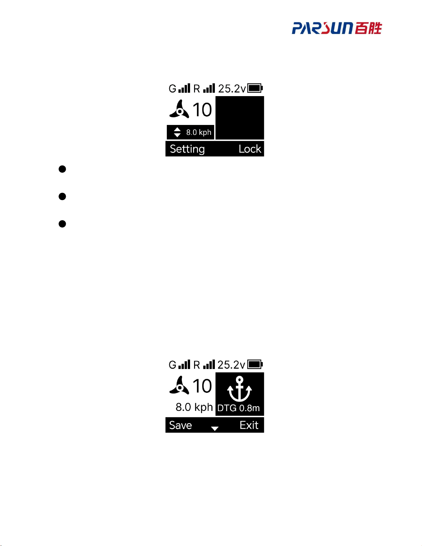
5.6.4 Anchoring mode
Press the “Anchoring on/off” button of remote control to enable [Anchoring mode].
● After this mode is enabled, the motor will be powered on automatically, and the unit will
anchor by taking the instantaneous coordinates where instruction is received as the anchor
point.
● Under this mode, the manual steering control of motor is invalid.
● Power off the motor under this mode to recover the steering control of motor.
37
● Press the “Anchor” button of remote control again to exit [Anchoring mode].
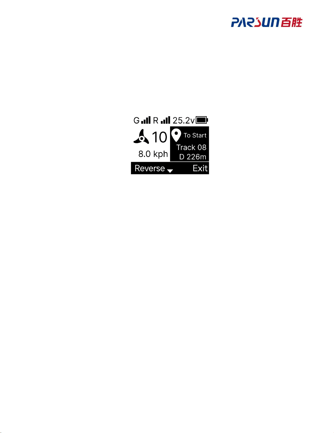
5.6.5 Navigation mode
Press the “Navigation function menu” button of remote control to enter navigation page, then
select “Route” and enter navigation - route page. Select the position where route is saved,
press the “Menu left mapping” button, select to end point/to start point and enable [Navigation
mode].
● After this mode is enabled, the motor will be powered on automatically and unit will drive
along with the set route.
● There are two options when this mode is enabled
● To Start, start from the “end point” of route and end at the “start point”.
● To End, start from the “start point” of route and end at the “end point”.
● Depart from the nearest point of route, whatever the mode.
● [Cruise mode] can be entered along with this mode.
● Press “Exit” in the menu bar at the bottom of the screen to exit [Navigation mode].
Invert route
Enter [Navigation mode], press the “Up” or “Down” button of remote control menu, switch the
screen bottom menu to show invert route on the left side, and show quit menu bar on the right
side. Press the “Menu left mapping” button to invert the route. After inversion is done, To Start
on screen will become To End; on the contrary, To End will become To Start.
38
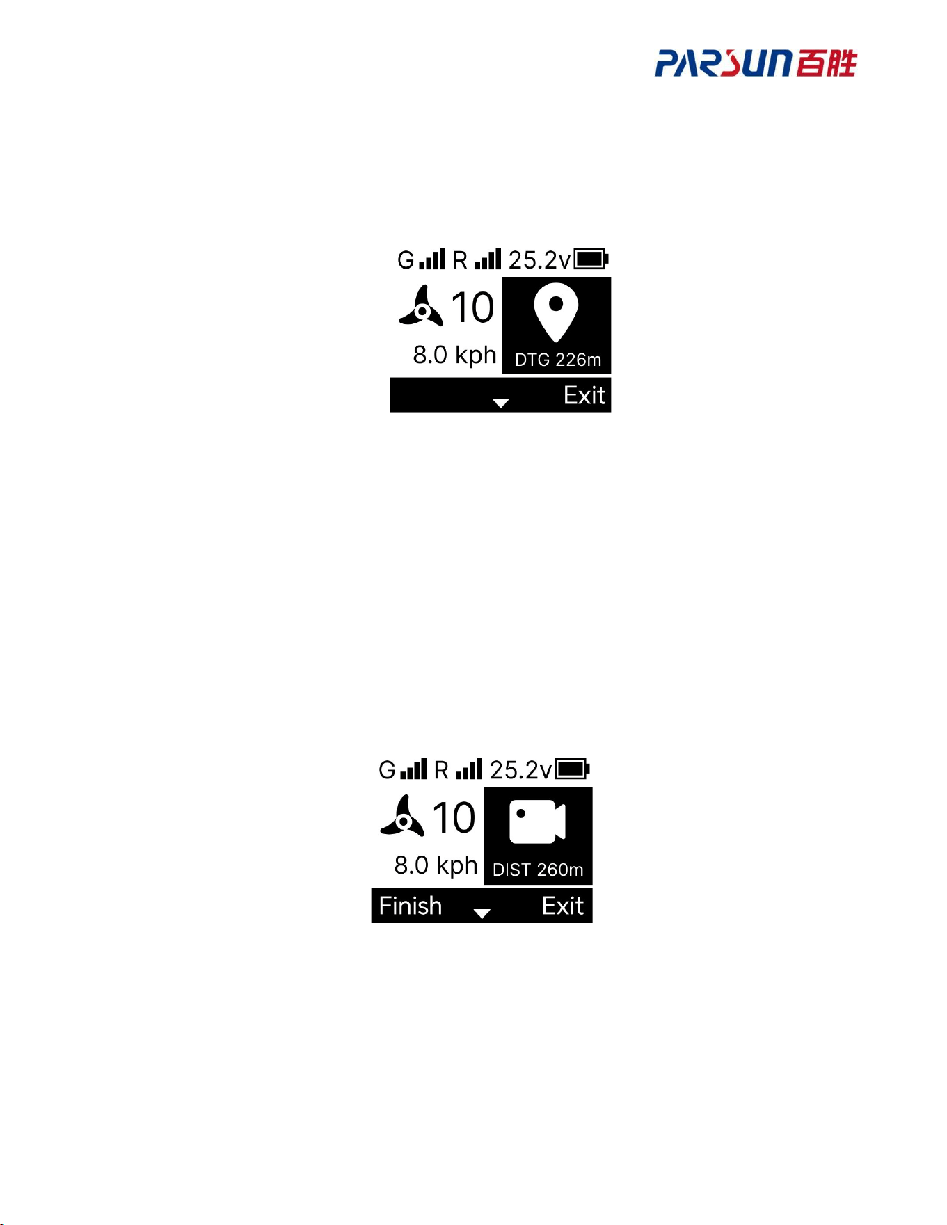
5.6.6 GoTo mode
Press the “Navigation function menu” button of remote control to enter navigation page, then
select waypoint to enter navigation - waypoint page. Select a position where waypoint is
saved, press the “Menu left mapping” button to enable [GoTo mode].
● After this mode is enabled, the motor will be powered on automatically and the unit will
drive to the target waypoint along with straight line.
● This mode can be enabled under [Bow/heading hold mode], [Cruise mode] and [Navigation
mode], and [Cruise mode] can be enabled along with this mode.
● This mode is invalid under [Record route mode] and [Anchoring mode].
● [Anchoring mode] will be enabled automatically after reaching the target waypoint.
● Press Exit of bottom menu bar to exit [GoTo mode].
5.6.7 Record route mode
Press the “Enable route record mode” button of remote control to enable [Record route mode].
● After this mode is enabled, the ship controller can record the track of route.
● This mode can be enabled under [Manual mode], [Bow hold mode], [Heading hold mode]
and [Cruise mode], all of which can be enabled with this mode.
● This mode is invalid under [Navigation mode], [GoTo mode] and [Anchoring mode].
● The longest distance of recorded route is 5km. When exceeding 5km, the remote control will
save the recorded route automatically and quit [Record route mode]
● Press Exit of screen bottom menu bar to quit [Record route mode].

39
Save the recorded route
Enter [Record route mode], press the “Up” or “Down” button of remote control menu,
switch the screen bottom menu bar to show completion on the left side, and show quit menu
bar on the right side. Press [Menu left mapping] button to quit [Record route mode] and save
the route to the remote control.
5.6.8 Anchoring shifting
After “Heading sensor” is connected, the anchor point can be shifted through push left, right
push, push up and push down joystick of remote control under anchoring mode.
Single push left: Move the anchor point to the left by 1m in comparison with heading
sensor direction.
Single push right: Move the anchor point to the right by 1m in comparison with heading
sensor direction.
Single push up: Move the anchor point to the front by 1m in comparison with heading
sensor direction.
Single push down: Move the anchor point to the back by 1m in comparison with heading
sensor direction.
5.7 Remote control setting
5.7.1 Calibration
Calibrate the ship controller magnetometer and heading sensor magnetometer.
1. Press the “Up” or “Down” button of remote control on the homepage to switch the screen
bottom menu, show the setting menu bar on the left side and show screen lock on the right
side.
2. Press the “Select left” button to enter the setting page.
3. Press the “Up” or “Down” button to search the calibration menu, press the “Select left”
button and select “Calibrate” to enter calibration page, the propeller starts calibration, and the
interface shows calibration progress bar. After calibration is done, the page shows completion
and jumps to setting list page.
5.7.2 Ship size
The ship size setting may cause different thrust of motor, to balance the thrust of ships
with different sizes. Please confirm whether the ship size setting matches your ship;

40
otherwise, it may affect the accuracy of function mode
1. Press the “Up” or “Down” button of remote control on the homepage to switch the screen
bottom menu, show the setting menu bar on the left side and show screen lock on the right
side.
2. Press the “Select left” button to enter the setting page.
3. Press the “Up” or “Down” button to search the ship size menu, then press the “Select left”
button to select “Ship size” and enter ship size setting page.
4. Press the “Up” or “Down” button to select the current ship size, then press the “Select left”
to save the settings.
5.7.3 Measuring unit
When it is set as metric unit, the unit of remote control is m, km and kph; when it set as British
unit, the unit of remote control is ft, nm and mph
1. Press the “Up” or “Down” button of remote control on the homepage to switch the screen
bottom menu, show the setting menu bar on the left side and show screen lock on the right
side.
2. Press the “Select left” button to enter the setting page.
3. Press the “Up” or “Down” button to search the measurement unit menu, press the “Select
left” button, select “Measurement unit” to enter measurement menu setting page.
4. Press the “Up” or “Down” button to select “Metric unit” or “British unit”, then press the
“Select left” and select “Save settings”.
5.7.4 Language
Set remote control language
1. Press the “Up” or “Down” button of remote control on the homepage to switch the screen
bottom menu, show the setting menu bar on the left side and show screen lock on the right
side.
2. Press the “Select left” button to enter the setting page.
3. Press the “Up” or “Down” button to search the language menu, press the “Select left” to
select “Language” and enter language setting page.
4. Press the “Up” or “Down” button to select “English” or “Chinese”, then press the “Select
left” to save the settings and change the language of remote control.

41
5.7.5 Backlight
Set backlight brightness
1. Press the “Up” or “Down” button of remote control on the homepage to switch the screen
bottom menu, show the setting menu bar on the left side and show screen lock on the right
side.
2. Press the “Select left” button to enter the setting page.
3. Press the “Up” or “Down” button to search backlight menu, press the “Select left” to select
“Backlight” and enter setting - backlight page.
4. Press the “Up” or “Down” button to select “Brightness” and enter brightness setting page.
5. Press the “Up” or “Down” button to select different brightness, then press the “Select left”
to save the settings.
Set backlight on time
1. Enter setting - backlight page.
2. Press the “Up” or “Down” button to select “Backlight time”, enter backlight time setting
page.
3. Press the “Up” or “Down” button to select the backlight lasting time, then press the “Select
left” to save the settings.
5.7.6 Auto shutdown
Set the auto shutdown time of remote controller. Auto shutdown will be executed only
when ship control system is not connected
1. Press the “Up” or “Down” button of remote control on the homepage to switch the screen
bottom menu, show the setting menu bar on the left side and show screen lock on the right
side.
2. Press the “Select left” button to enter the setting page.
3. Press the “Up” or “Down” button to search the auto shutdown menu, press the “Select left”
button and select “Auto shutdown” to enter setting - auto shutdown page.
4. Press the “Up” or “Down” button to select auto shutdown time of idle remote control, then
press the “Select left” button to save the settings.
5.7.7 Propeller revolving speed
Set display propeller as icon or propeller revolving speed
1. Press the “Up” or “Down” button of remote control on the homepage to switch the screen
bottom menu, show the setting menu bar on the left side and show screen lock on the right
42
side.
2. Press the “Select left” button to enter the setting page.
3. Press the “Up” or “Down” button to search the auto shutdown menu, press the “Select left”
and select “Propeller revolving speed” to enter setting - propeller revolving speed page.
4. Press the “Up” or “Down” button to select the display style of propeller revolving speed,
then press the “Select left” to save the settings.
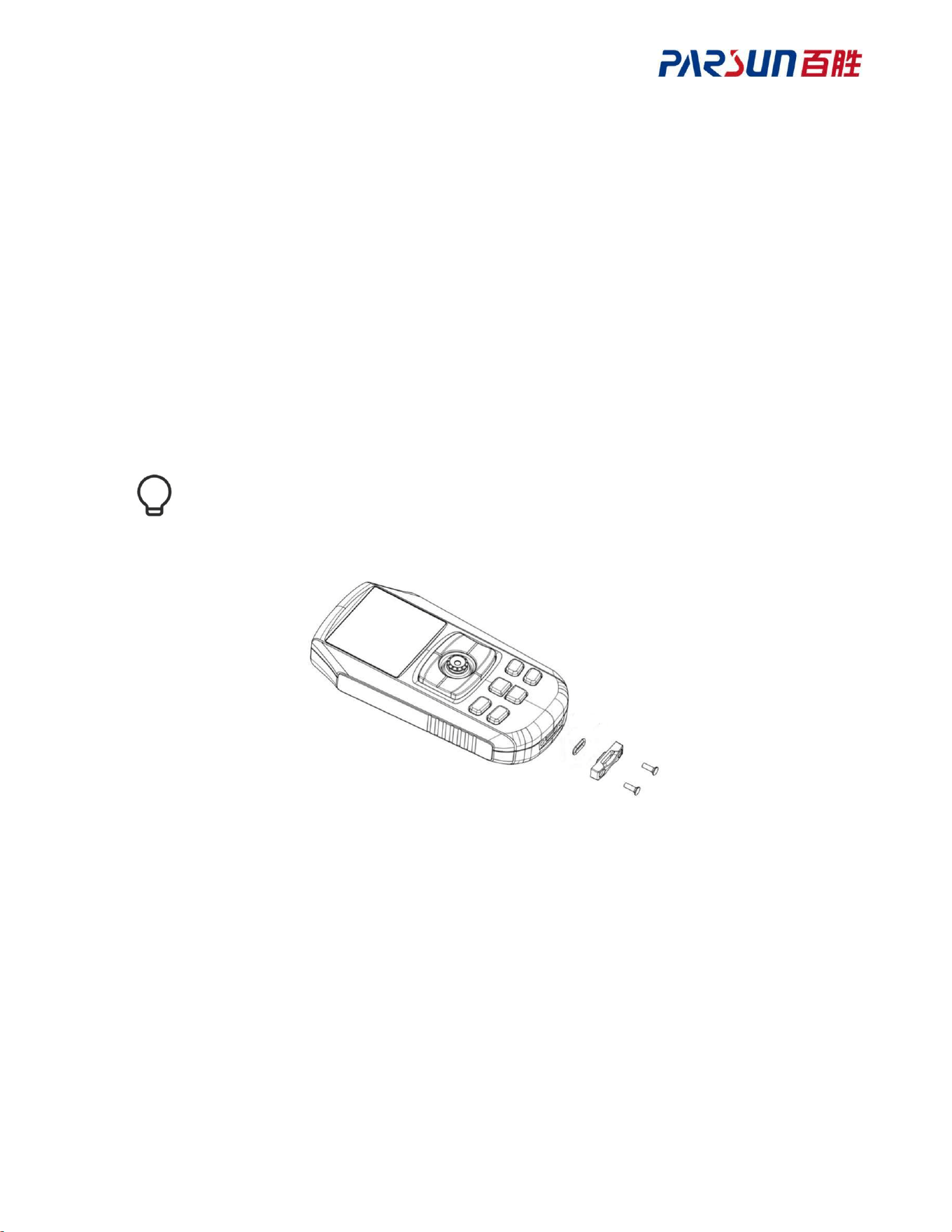
5.8 Remote control charging
Remove the cover of the charging port at the bottom of the remote control for charging. Please
use a device with Type-C charging port, charging voltage of 5V and current of 1A for charging
the remote control.
After charging is done, lock the cover of charging port and ensure that the seal ring is
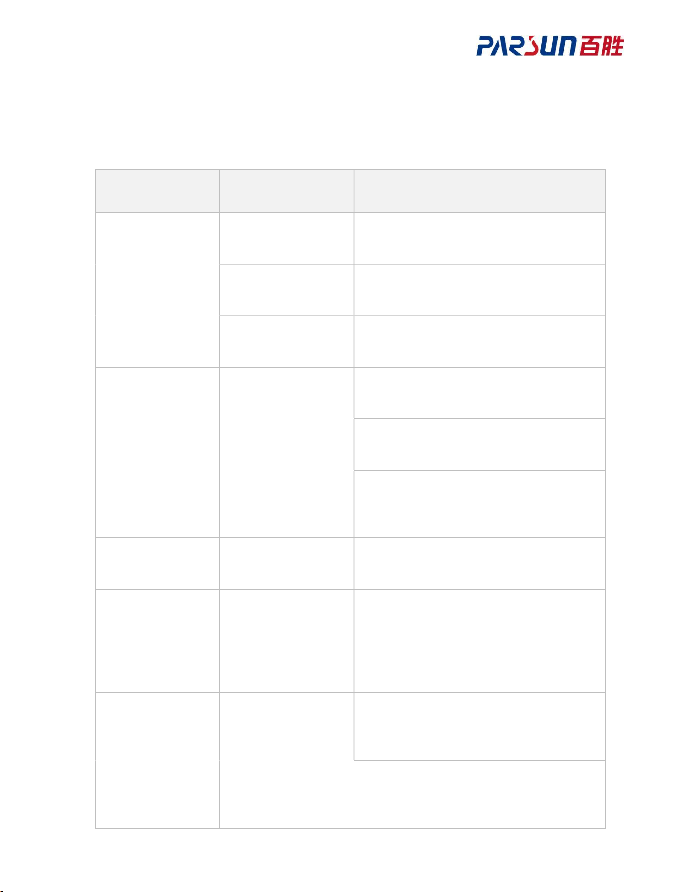
on the cover.
43
6 Fault Code and Prompt
6.1 Unit indicator and buzzer
Prompt tone mode Unit indicator Description
NA
Green indicator in
slow flickering
Remote control is not connected.
Red indicator in slow
flickering
Ship control panel tilt is over 80°, please
lay it flat.
White indicator in
slow flickering
Spring wire is broken or socket is loose.
One beep NA
Motor level up/down (motor is powered
on).
Power on/off motor.
Enable or disable anchoring, navigation,
cruise, bow/heading hold, record route
mode.
One beep
Red indicator in slow
flickering
Unit failure, refer to “Fault Codes”
Three beeps
Green indicator in
fast flickering
Remote control pairing in progress.
Five beeps NA Remote control pairing succeeds.
Two continuous
beeps
Yellow indicator in
slow flickering
Too low working voltage
For 12V model, voltage should be >10V.
For 24V model, voltage should be >17V.
When the temperature inside the drive is
too high, please power off the motor, and
ensure that the surroundings of drive are
44
clear and normally ventilated.
Two continuous
beeps
Yellow indicator in
fast flickering
Please remove the foreign matters which
are wrapped around the propeller of motor.
Three continuous
beeps
Yellow indicator in
fast flickering
Too high working voltage.
For 12V model, voltage should be < 18V.
For 24V model, voltage should be < 32V.
Spring wire is blocked, please untangle it.
Unit current exceeds the threshold; check if
the propeller is blocked.
6.2 Heading sensor indicator
Indicator Description
Green indicator in
slow flickering
Normal lighting
Green indicator in
fast flickering
Excessive tilting angle
Red indicator in
slow flickering
Communication disconnected
Red indicator in fast
flickering
Sensor error
6.3 Remote control fault prompt
Fault prompt Description
Too high power voltage
Too high working voltage.
For 12V model, voltage should be < 18V.
For 24V model, voltage should be < 32V.
Too low power voltage
Too low working voltage.
For 12V model, voltage should be >10V.
45
For 24V model, voltage should be >17V.
Too high unit current
Please remove the foreign matters which are wrapped around the
propeller of motor.
Steering motor error Spring wire is blocked, please untangle it.
Too high drive
temperature
Drive internal temperature is too high, please power off the
motor, and ensure that the surroundings of drive are clear and
ventilation is normal.
Motor error
Unit current exceeds the threshold, please confirm whether
propeller is blocked.
Ship control gyroscope
error
Use remote control to recalibrate the accelerometer.
Ship control
accelerometer error
Keep away from magnetic object.
Magnetic field has
major changes.
Keep away from magnetic object.
Too high magnetic field
interference
Keep away from magnetic object.
Magnetometer timeout Ship control sensor error, repairing is required.
GPS module error GPS module has error, try to restart the unit.
System power supply
error
Ship control power supply error, repairing is required.
Sensor error Ship control sensor error, repairing is required.
46
7 Maintenance
7.1 Routine maintenance
Proper maintenance helps extend the service life of TM120B. Please maintain TM120B in
accordance with the following regulations.
Disconnect the battery when TM120B is not in use.
Store TM120B on deck when not in use.
Rinse the unit's surface with fresh water after use in a saltwater environment.
Check whether the base mounting screws are loose.
Inspect the propeller for scratches, fractures, entanglement, etc.
Check the wiring harness for any damage to the insulation, breakage, and similar issues.
7.2 Maintenance schedule
Item Interval Operation
Terminal Once a week
Check the wire harness electronics for
corrosion or dirt.
Spring wire Every 6 months Visually inspect for any damage or breakage.
Anode Every 6 months Check if the anode has failed.
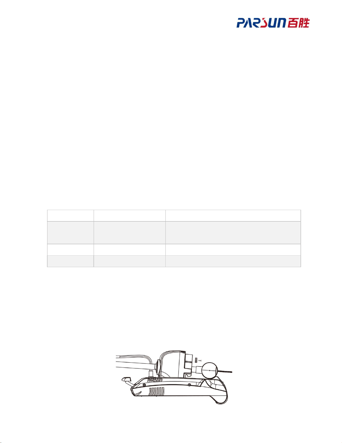
7.3 Anode replacement
TM120B is equipped with two anodes. One is located on the propeller; for replacement, refer
to “Propeller Installation.”
The other anode is positioned beneath the steering device; please replace it by referring to the
diagram below.

47
8 Warranty
8.1 Limited Warranty
Suzhou Parsun Power Technology Co., Ltd. (hereinafter referred to as "Parsun Power")
promises that, provided the product is correctly installed, routinely maintained, and used
normally, it will be free from defects in materials and workmanship for twenty-four months
from the date of delivery to the end customer. This warranty is only provided to the first end
customer of Parsun Power products. During this period, the customer has the right to request
free repair or replacement of defective or non-compliant parts; i.e., "Limited Warranty Period".
During the warranty period, Parsun Power bears the repair costs directly caused by the product
issues and other related expenses (such as costs related to product installation, disassembly,
transportation, financing, leasing, etc.) only. Any expenses unrelated to or exceeding the scope
of the limited warranty will be borne by the customer. After the warranty period expires,
customer can still enjoy repair services provided by Parsun Power and its authorized
dealers/distributors (hereinafter referred to as “Parsun Power Service Partners”) by charging
the lowest repairing fees.
In addition to the warranty services herein, customers may have statutory rights under the
applicable laws of their jurisdiction. The contents specified in the warranty provisions do not
affect such statutory rights. Besides the rights granted under the warranty services, customers
also have the warranty claim rights pursuant to the purchase contract that they conclude with
Parsun Power Service Partners.
The warranty provisions herein do not apply to the products used for commercial or
professional purposes (such as the scenarios with a high frequency of use, requiring high
reliability or for profitable purpose, even if the machine is such used temporarily). The legal
warranty provisions within the local judicial region shall prevail. You are recommended to
consult the Parsun Power Service Partners to learn the warranty policies and relevant
suggestions before using TM120B for such purpose.
To ensure that your warranty application can be resolved in a timely manner, please learn and

48
comply with the following guidelines:
Any warranty claim should be submitted within six (6) months from the date the issue is
discovered. Failure to submit the claim within six months will be deemed a waiver of the
warranty, and no warranty service will be provided.
Keep TM120B's label intact and record the S/N on its label. Do not remove TM120B's
label. The warranty service does not apply to the products with no original product label.
This limited warranty is non-transferable and applies only to the original end customer.
8.2 Exceptions
The warranty service ceases to apply in any of the following circumstances:
Improper operation that does not comply with the instructions specified in the user
manual.
Problems caused by accidents, misuse, dropping, falling, improper maintenance or
storage, intentional damage, physical damage, overcharging, over-discharging, or
unauthorized repairs.
Water ingress caused by external factors such as fishing nets or prolonged underwater
immersion.
Unauthorized modification, alteration, disassembly, or installation of additional parts
(accessories) on the product.
Damage caused by the fault of any third-party product or any third-party product.
Consumables are beyond the warranty scope (e.g., propellers, anodes, etc.).
Products purchased from unauthorized dealers or sellers.
Normal wear and routine maintenance are not covered by the warranty.
Further damage occurring during transportation due to improper packaging (beyond the
scope of the warranty).
Lithium batteries are classified as Class 9 hazardous goods under the United Nations.
Their shipment and packaging must comply with the relevant regulations of the local
country. Non-compliance may result in the failure in enjoying the warranty services.
8.3 Process for applying for warranty (claim)
Customers shall apply for warranty (claim) as per the warranty (claim) procedure.
1. Contact the Parsun Power Service Partners near you. If the relevant faults fall under the

49
warranty scope of Parsun or Parsun Power Service Partners, they will provide further guidance
for you.
2. You need to provide and submit the purchase proofs (such as receipt, invoice; product
information and purchase date must be included in the proofs), the warranty card, factory serial
number together with the faulty product to the Service Partners. Please make sure that all the
labels remain intact. The warranty will only be valid if the above information is accurate,
authentic, and complete.
3. Ensure that the product is properly packaged during transportation; it is highly
recommended to use the original packaging.
4. The Parsun Power Service Partners will diagnose and inspect the faulty product to verify the
validity of the warranty claim.
5. If your warranty claim is approved, the product or the defective components/parts will be
repaired or replaced free of charge. Please be noted that all shipping costs incurred during this
process will be borne by you.
6. If your warranty claim is denied, the Service Partners will estimate the repair/replacement
costs and round-trip shipping fees and send the list of estimated costs to you for confirmation.
The Parsun Power Service Partners will not take the following actions until receiving your
written approval.
Special notice:
These warranty policies are subject to changes time to time. We will inform our service
partners immediately in case of any change. Where necessary, please consult our sales and
after-sales person, or local service partners in advance. Thank you!