1
Radioddity
UB15-G Manual

2
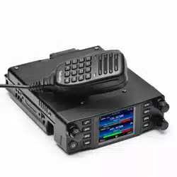
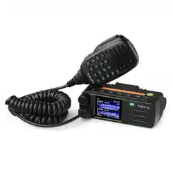
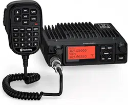
1. Overview
The UB15-G is a GMRS analog mobile transceiver.
It includes a main radio unit, a handheld microphone, and a mounting bracket.
2. Product Features
LCD display with 7 selectable backlight colors
LCD backlight brightness adjustable
Channel naming function
TX/RX indicator LED
Frequency Range: TX: GMRS;RX: 400–470MHz
80 Programmable channels(22 of which are GMRS fixed channels, the remaining channels are
editable for frequency.)
CALL TONE
Keyboard lock function
NOAA Weather (NOAA)
Dual Watch
High/Low power selection
Wide/Narrow bandwidth selection
Priority Channel (PRI)
Priority Channel Watch
Scan
Monitor (MONI)
Squelch (SQL)
Transmit Timeout Timer 180S (TOT)
CTCSS/DCS
Noise Reduction (NRC)
TX Noise Cancellation (ANC)
Key Beep
Transmit End Tone (ROGER BEEP)
VOX (9 levels)
Mic Gain (3 levels)
Voice Record Playback
3. Technical Specifications
GENERAL
Frequency Range
TX:GMRS Band RX:
400–470MHz
Channel Spacing 12.5KHz/25KHz
Channel Capacity
22 channels+8 Repeater channels+50 Programable
channels(Support GMRS Frequency only)
Frequency Stability
±300Hz
Operating Temperature
-30℃~+60℃
Operating Voltage
13.8V
3
Size 135*110*25
TRANSMITTER
Power Output
High
:
15W/ Low
:
5W
Emission current
High
:
5A/Low
:
1A
Modulation Limiting
Narrow
:≦
2.5KHz/Wide
:≦
5.0KHz
Adjacent Channel Power
Narrow
:≧
60dB/Wide
:≧
65dB
Hum& Noise ≧40dB
Audio Distortion ≦5%
Mic Sensitivity(@L2) 5-10mV
Antenna port hum 9KHz-1GHz:≦-50dBc
1GHz-12.75GHz
≦
-55dBc
RECEIVER
Sensitivity ≦-119dBm@SINAD=12dB
Audio Distortion ≦5%
Hum& Noise ≧45dB@25KHz/≧40dB@12.5KHz
Adjacent Channel Selectivity ≧[email protected]KHz/≧60dB@25KHz
Inter Modulation ≧60dB
Blocking or Desensitization
≧
84dB
Co-Channel Rejection
≧
-12dB
Max Audio Output@1KHz 8Ω
≧
1W
Standby Current
≦
360mA
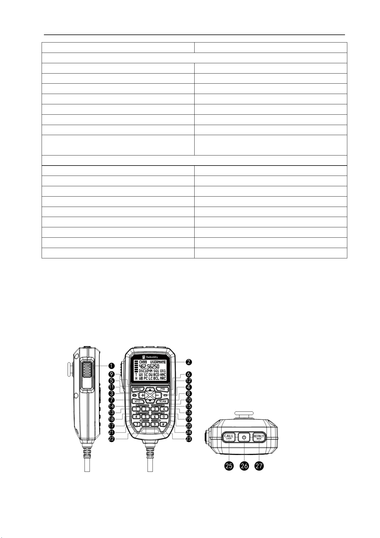
4. Structural Appearance
Microphone

4
NO
Name Short Press Long Press
1
PTT
Transmit/Save settings and
return to main screen
2
LCD
3
LED TX/RX Indicator
4
MIC
5 MENU
Enter Menu Mode
Enter Menu Options
Confirm changes and return to
previous menu
VFO Channel Store
6
PRI Recall Pri Channel Priority Channel Setup
7
VFO
Enter/Exit VFO Mode Delete Channel
8
Scan
Start / Stop Scan
Add channel to / Remove
channel from scan list
9
▽ CH-
Channel - Channel Continuous -
10
△ CH+
Channel + Channel Continuous +
11
+ Volume + Volume Continuous +
12
- Volume - Volume Continuous -
13
1
Digit 1
14
2
Digit 2
15
3
Digit 3
16
*
Back Key Enter/Exit Weather Mode
17
4
Digit 4
18
5
Digit 5
19
6
Digit 6
5
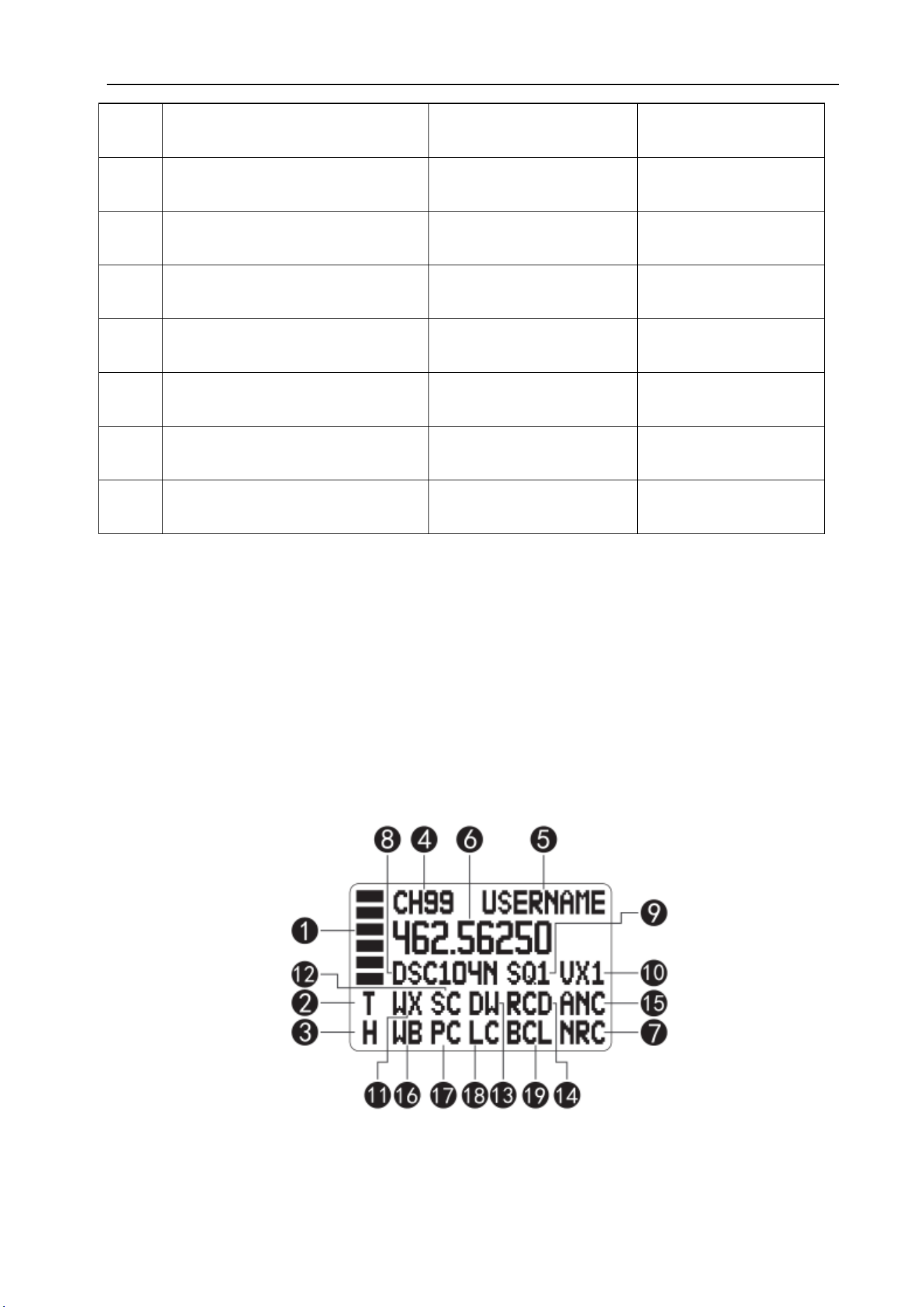
5. LCD Display Indicators
20
0
Digit 0
Start / Finish Channel
Name Edit
21
7
Digit 7
22
8
Digit 8
23
9
Digit 9
24
#
VFO Frequency Confirm Key
Turn On / Turn Off Dual
Watch
25
CALL/LOCK
Transmit CALL TONE Keyboard Lock / Unlock
26
Power button
Power On / Off
27
REPLAY/MON
Voice Record Playback Monitor On / Off
6
NO
Symbol
Description
NO
Symbol
Description
1
Transmit/Receive Strength Indicator
11
WX
Weather Forecast Indicator
2
T
T
TX Indicator
12
SC
Not
Blinking
Scan List Indicator
R
RX Indicator
M
Monitor Indicator
Blinking
Scanning
3
H
H
High Power
Indicator
13
DW
Dual Watch
L
Low Power Indicator
4
CH99
Channel No.
14
RCD
Record On
5
USERNAME
Channel Name
15
ANC
TX Noise Reduction On
6
462.5625
Channel Frequency
16
WB
NB
Narrow Band
WB
Wide Band
7
NRC
RX Noise Reduction On
17
PC
Priority Channel Indicator
8
DCS104
CTC/DCS Indicator
18
LC
Keyboard Lock Indicator
9
SQ1
SQ Level Indicator
19
BCL
Busy Lock
VOL 01
While Adjusting Volume
10
VX1
VOX Level Indicator
6. Function Introduction
6.1 Power on/off
Power on the radio by long-pressing the power button when it is off.
Press and hold the power button for 2 seconds to turn off the radio when it is on.
High voltage alarm: If the supply voltage exceeds 16V, the radio will emit a high-voltage alert tone,
display “DCH” on the LCD, and disable transmission.
Low voltage alarm: If the supply voltage drops below 10V, the radio will emit a low-voltage alert tone
and display “DCL” on the LCD.
Low voltage auto power-off: If the supply voltage drops below 9V, the radio will power off automatically.
6.2 Channel Selection
Users can select the current working channel using the △/▽ buttons on the hand microphone, or
directly enter the channel number via the numeric keypad and press the # key to quickly switch
channels.(Example: Enter 05 and press #, the radio will switch to Channel 5.)
6.3 Volume Adjustment
Users can increase or decrease the radio's receive volume using the VOL+ / VOL- buttons on the hand

7
microphone.The unit supports a total of 10 volume levels from 0 to 9.
6.4 Transmit & Receive
To communicate between two radios, both must be set to the same frequency and CTC/DCS code.
To make a call, press and hold the PTT button on the microphone and speak into it in a normal voice.
Note: For best clarity, hold the microphone 2 to 3 inches from your mouth while speaking.
The T icon will appear continuously on the LCD during transmission.The R icon will appear continuously
on the LCD during reception.
6.5 Squelch Level Adjustment
Users can adjust the squelch sensitivity level via the menu.This radio provides 10 squelch levels (0–9).
0 – Squelch open
1 – Maximum sensitivity (minimum squelch)
5 – Medium sensitivity (medium squelch)
9 – Minimum sensitivity (maximum squelch)
6.6 CTCSS/DCS Settings
Users can set the sub-audible tones of the radio via the menu.This radio provides 38 groups of analog
tones (CTCSS) and 208 groups of digital tones (104 groups of DCSN + 104 groups of DCSI).Refer to the
bottom of this manual for the sub-audible tone frequency list.
6.7 Power Level Setting
The radio offers two power levels, high and low, for users to choose from.Users can select different
power levels according to different scenarios.
Note: Channels 1–7 are set to low power by default and cannot be changed.
6.8 Priority Channel - Set / Recall / Watch
To allow users to quickly switch to frequently used channels, this radio provides priority channel setting
and recall functions.
Setting:Users can switch to a frequently used channel using the channel keys, then long-press the PRI
button to set it as the priority channel.The PC icon will appear above the channel display.
Recall:During operation, short-press the PRI button to toggle between the current channel and the
priority channel.
Watch Function:When the Pri Watch function is enabled, the radio will scan the priority channel
intermittently during scanning (every 1 seconds).
Dual Watch:The Dual Watch function continuously monitors both the current channel and the priority
channel.
Long-press the # key to enable Dual Watch; the DW icon will appear.

8
Long-press the # key again to disable Dual Watch; the DW icon will disappear.
6.9 Scan Function
Adding & Removing from Scan List
Users can add the current channel to the scan list or remove it by long-pressing the Scan button.When the
channel is in the scan list, the SC icon will appear on the LCD.
This radio provides three scan modes for selection: SE / CO / TO.
SE:In this mode, scanning stops automatically when a signal is detected and stays on that channel.To
resume scanning, you must restart it manually.
CO:In this mode, scanning pauses on the channel when a signal is detected.If the signal disappears, the
radio resumes scanning after 5 seconds.
TO:In this mode, scanning pauses on the channel when a signal is detected.The radio automatically
resumes scanning after 5 seconds, regardless of the signal.
In addition, if PTT is pressed during scanning, the radio will transmit on the currently detected
channel.After releasing PTT, the radio stays on that channel for 10 seconds, then resumes scanning.
6.10 VOX (Voice-Operated Transmit)
This radio features a VOX (voice-activated) function for user convenience.When enabled, speaking
directly into the microphone will automatically trigger transmission.
The function has 9 sensitivity levels.The higher the level, the louder the voice required to activate VOX
transmission.
Recommendation:Enable the ANC function at the same time as VOX to prevent VOX from being
triggered by ambient noise.
6.11 RX Noise Reduction (NRC)/ TX Noise Reduction(ANC)
NRC:When this function is enabled, the radio will greatly reduce (but not completely eliminate)
non-voice noise from the transmitted signal during reception, improving the user experience.
ANC:When this function is enabled, ambient noise will be filtered out, and only human voice will be
transmitted.
6.12 Busy Channel Lockout (Busy Lock)
When this function is enabled, pressing PTT while the radio is receiving will not trigger transmission.The
radio will emit a continuous transmit-prohibit tone until the PTT button is released.
6.13 Transmit Timeout Timer (TOT)
When the transmit time-out function is enabled and a time is set, the radio will stop transmitting once the
set duration is reached after you press and hold PTT.To continue transmitting, release PTT and press it
again.
9
6.14 Microphone Gain Adjustment
Users can adjust the microphone sensitivity via the menu.This radio offers 3 sensitivity levels (L1 / L2 /
L3).The higher the level, the more sensitive the microphone.
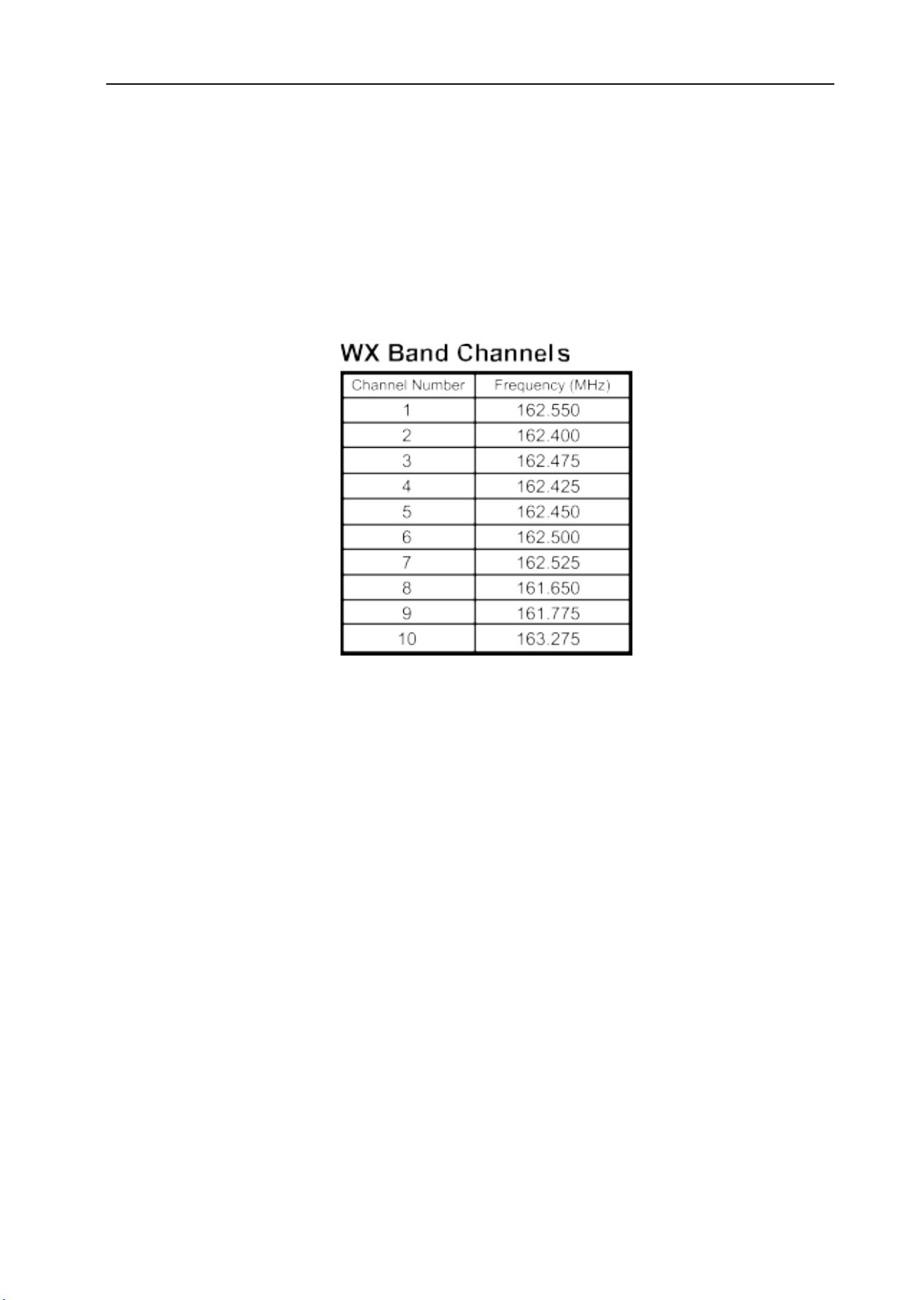
6.15 NOAA Weather Radio (Scan / Monitor / Alert)
The UB15-G is equipped with Weather Receive and Weather Alert functions, which can directly obtain
information about severe weather events or domestic emergencies from the National Weather Service
(NWS) of the United States, allowing you to take appropriate actions to ensure safety.
Weather Scan
Long press the * key for 2 seconds to enter Weather Mode.The radio will automatically scan active
weather channels, with the WX icon blinking.Scanning stops and switches to receive mode when a signal
is detected. Press the channel key to resume scanning.
Long press the * key again for 2 seconds to exit Weather Mode; the WX icon will disappear.
Weather Monitor
In Weather Scan mode, short press the SCAN key to stop scanning and enter monitor mode.To resume
scanning in Weather Monitor mode, short press SCAN again.
Weather Alert
In Weather Monitor mode, use the channel keys to select your desired weather alert channel, then short
press MENU to enter the Weather Alert on/off setting.Use the channel keys to select ON or OFF.
When Weather Alert is ON:
In Weather Mode, a weather alert tone (1050Hz) on any channel will trigger the alert.
In radio channel mode, the WX icon continues blinking, and the radio monitors the last used weather
channel.
When a weather alert is triggered, press any key to acknowledge the alert, and the radio will enter
Weather Receive mode.If the radio remains in Weather Mode and continues receiving weather alert
signals, the alert will sound again after 20 seconds.

10
6.16 Frequency Mode (VFO)
Users can manually set the radio’s channel frequency using this function.The frequency setting range is
400–470 MHz.
Note: Transmission is allowed only on GMRS frequencies and GMRS repeater frequencies.All other
frequencies are for reception only.
How to Edit Frequency
Short press the VFO button to enter VFO mode.You may then:
Enter the frequency directly using the numeric keypad, or
Adjust by preset frequency steps using the channel up/down keys.
After entering the frequency, short press the # key to confirm.
How to Adjust Frequency Step
Short press MENU to enter menu mode.Use channel up/down keys to select the Step menu.Press MENU
again to enter step setting.Use channel up/down keys to select your desired step value, then press * to
confirm.
Available steps:2.5 kHz / 5.0 kHz / 6.25 kHz / 12.5 kHz / 25 kHz / 50 kHz / 100 kHz
Factory default: 12.5 kHz
Storing Custom Channels
After setting your custom frequency, long press MENU to enter save mode.The default channel (flashing)
is the nearest empty channel.Use the up/down keys to select your desired storage channel.Long press
MENU again to save the channel and exit.
If the selected channel already contains data, the radio will prompt:“Overwrite CH?”
Press MENU to overwrite the existing channel.
Press * or PTT to cancel.
Notes:
If the stored custom frequency matches GMRS channels 1–7, high power is not allowed on that channel.
If the stored custom frequency matches GMRS channels 8–14, transmission is not allowed on that
channel.
Deleting Custom Channels
From the channel interface, select the channel to delete using the channel keys.Long press VFO to delete
the channel.
The radio will prompt:“Delete CH?”
Press MENU to confirm deletion.
Press * or PTT to cancel and keep the channel.
Note:Only custom-edited channels can be deleted.GMRS channels and repeater channels cannot be
deleted.An error tone will sound if deletion is attempted on GMRS or repeater channels.
6.17 Repeater Channels
Repeater channels are used to communicate with a repeater, allowing it to retransmit your signal.Repeater
channels extend the radio communication range and overcome shielding caused by solid obstacles.In
conventional direct mode, your radio transmits and receives on a single fixed frequency.
Reception will be weak if obstacles block the signal, as hills, tall buildings, metal structures and similar

11
objects often create shielding between radios.When using a repeater channel, the signal from your radio is
received by the repeater and retransmitted on a different frequency simultaneously, enabling much
longer-distance communication.
Enabling and Disabling Repeater Channels
Users can enable or disable repeater channels via the Repeater menu.When repeater channels are enabled,
8 additional repeater channels are added to the original channel list as shown below:
Channels before enabling repeater function:CH01 - CH02 - CH03 - … - CH15 - CH16 - CH17 - … -
CH22
Channels after enabling repeater function:CH01 - CH02 - CH03 - … - CH15 - CH15RP - CH16 -
CH16RP - CH17 - CH17RP - … - CH22 - CH22RP
6.18 Reset (Restore Factory Settings)
Users can reset the radio via the Reset menu.After entering this menu, select Yes to restore the radio to its
factory default settings, or select No to cancel and exit the reset menu.
The factory settings after reset are as follows:
Channel
GMRS 01
CTC/DCS
OFF
SQ
1
NRC Level
OFF
Scan List
All Channels
VOX
OFF
Key Beep
ON
VOX Level
L1
Roger Beep ON Backlight Color White
Backlight Brightness L2 RX Noise Reduction
(NRC)
OFF
Busy Channel
Lockout
OFF
TX Noise Reduction
(ANC)
OFF
Backlight Timeout 30S Priority Channel 02
Mic Gain
L2
Priority Watch (Pri
Watch)
On
6.19 Channel Name Edit Function
Users can edit the channel name via the radio’s keypad or programming software.The channel name
supports a maximum of 8 characters, and each character can be selected from 0–9 and A–Z.
How to Set Channel Name via Radio Keypad
The default channel name is: USERNAME
Long press the 0 key to enter channel name editing mode.The first character “U” will start
flashing.Users can edit this position using the △ CH+ / ▽ CH– keys (0–9, A–Z).
After editing the first character, use the + /
– keys to move the cursor to the previous or next position
for further editing.
Once you have finished editing the desired channel name, long press the 0 key again to save and complete
the setup.
6.20 Voice Recording & Playback
The radio can automatically store up to 20 recordings, each up to 1 minute in length.

12
The recording function will automatically record received audio in the following modes:
CB receive channels
Scan mode
Note: Recording does not occur in monitor mode or when squelch is set to SQ=0.
Short press the REPLAY button to play the most recent received message by default.
During playback, the display shows RPY and the current recording number.Users can use the △ CH+ /
▽ CH–keys to switch between recordings for playback.
After playback finishes, a long confirmation tone will sound, and the radio will return to channel mode.
The recording function can be enabled or disabled via the menu.
Notes:
Maximum number of recordings: 20.
Audio shorter than 500 ms will not be recorded.
The radio stops receiving signals during playback.
New recordings automatically overwrite the oldest ones when memory is full.
Transmit (TX) audio is not recorded.
6.21 Main Unit + Hand Mic Dual Speaker Mode
This radio is equipped with one speaker on both the main unit and the hand mic.Users can set their
preferred speaker operating mode via the menu.
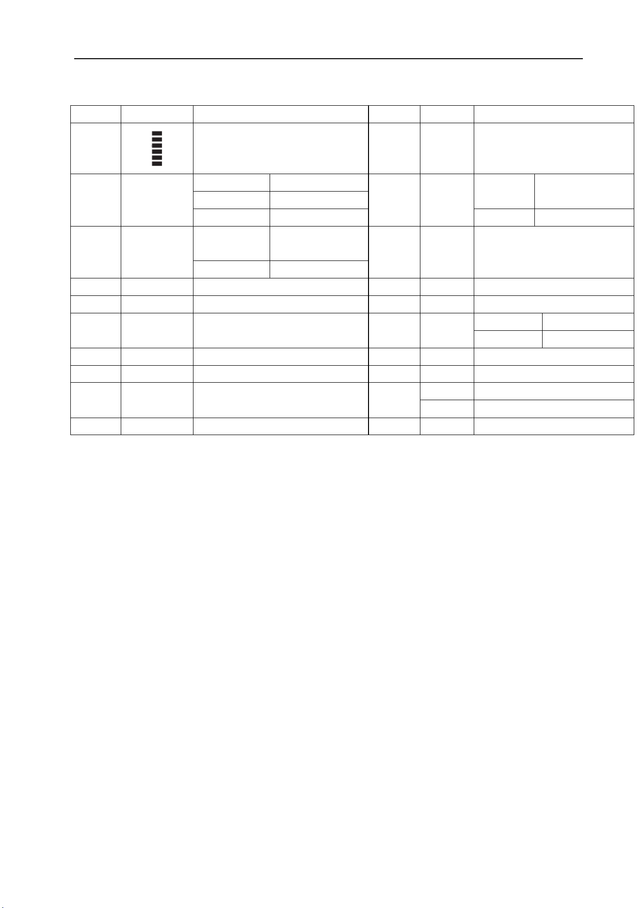
7. Menu Description
Main Menu Submenu Option Description
Scan Scan/Skip
Scan: channel included in scan
list.
Skip: channel excluded from
scan list.
Scan mode Se、Co、To Default: Co
CTCSS/DCS OFF/CTC/DCS 38 CTCSS / 208 DCS Sets sub-audio signaling.
TX POWER Hi/Lo
Power for channels 1
–
7 is
fixed and non-adjustable.
VOX OFF/L1/L2/L3/
L4/L5/L6/L7/L
8/L9
NRC ON/OFF ON: NRC Enabled
OFF: NRC Disabled
ANC
ON/OFF
ON: ARC Enabled
OFF: ARC Disabled
Bandwidth
Narrow/Wide
Select wideband or
narrowband.

13
Backlight OFF/L1/L2/L3 LCD backlight brightness
level.
Backlight Color
White / Blue /
Green / Red /
Cyan / Purple /
Yellow
LCD backlight color selection.
Backlight Time
Always/10s/
20s/30s
Backlight timeout duration.
Key Beep ON/OFF
Enables or disables keypad
tone.
Replay ON/OFF Default: ON
SQL 0-9 Squelch level adjustment.
TOT
OFF/60S/120S/
180S
OFF: No Time-out Timer
60S / 120S / 180S
Call Tone 01-10 Default: 01
PRI WATCH ON/OFF
ON: Scans the priority channel
every 1.5 seconds after
scanning starts
OFF: Does not scan the
priority channel
Repeater ON/OFF
ON: Repeater Channel
Enabled
OFF: Repeater Channel
Disabled
Speaker
Dual/Base/Rem
ote
Dual: Both main unit and hand
mic speakers active
Base: Only main unit speaker
active
Remote: Only hand mic
speaker active
Roger Beep ON/OFF
Enables or disables
transmission end tone.
Mic Gain
L1/L2/L3
Microphone sensitivity level.
Busy Lock ON/OFF
ON: Transmission prohibited
during reception.
OFF: Transmission permitted
during reception.
VFO Step
2.5KHz/5.0KH
z/6.25KHz/12.5
KHz/25KHz/50
KHz/100KHz
Default: 12.5kHz
Reset Yes/No
Yes: Start resetting.
No: Do not reset.
Version Firmware version.

14
8. CTCSS Table
CTCSS
Number
Frequency
Hz
CTCSS
Number
Frequency
Hz
CTCSS
Number
Frequency
Hz
CTCSS
Number
Frequency
Hz
1 67.0 11 97.4 21 136.5 31 192.8
2 71.9 12 100.0 22 141.3 32 203.5
3 74.4 13 103.5 23 146.2 33 210.7
4 77.0 14 107.2 24 151.4 34 218.1
5 79.7 15 110.9 25 156.7 35 225.7
6 82.5 16 114.8 26 162.2 36 233.6
7 85.4 17 118.8 27 167.9 37 241.8
8 88.5 18 123.0 28 173.8 38 250.3
9 91.5 19 127.3 29 179.9
10 94.8 20 131.8 30 186.2
9. DCS Table
DCS-N Table
CDCSS
Number
Octal Code CDCSS
Number
Octal Code CDCSS
Number
Octal Code CDCSS
Number
Octal Code
1 023N 27 152N 53 311N 79 466N
2 025N 28 155N 54 315N 80 503N
3 026N 29 156N 55 325N 81 506N
4 031N 30 162N 56 331N 82 516N
5 032N 31 165N 57 332N 83 523N
6 036N 32 172N 58 343N 84 526N
7 043N 33 174N 59 346N 85 532N
8 047N 34 205N 60 351N 86 546N
9 051N 35 212N 61 356N 87 565N
10 053N 36 223N 62 364N 88 606N
11 054N 37 225N 63 365N 89 612N
12 065N 38 226N 64 371N 90 624N
13 071N 39 243N 65 411N 91 627N
14 072N 40 244N 66 412N 92 631N
15 073N 41 245N 67 413N 93 632N
16 074N 42 246N 68 423N 94 654N
17 114N 43 251N 69 431N 95 662N
18 115N 44 252N 70 432N 96 664N
19 116N 45 255N 71 445N 97 703N
20 122N 46 261N 72 446N 98 712N
21 125N 47 263N 73 452N 99 723N
22 131N 48 265N 74 454N 100 731N

15
23 132N 49 266N 75 455N 101 732N
24 134N 50 271N 76 462N 102 734N
25 143N 51 274N 77 464N 103 743N
26 145N 52 306N 78 465N 104 754N
DCS-I Table
CDCSS
Octal
Code
CDCSS
Octal
Code
CDCSS
Octal
Code
CDCSS
Octal
Code
Number Number Number Number
105 023I 131 152I 157 311I 183 466I
106 025I 132 155I 158 315I 184 503I
107 026I 133 156I 159 325I 185 506I
108 031I 134 162I 160 331I 186 516I
109 032I 135 165I 161 332I 187 523I
110 036I 136 172I 162 343I 188 526I
111 043I 137 174I 163 346I 189 532I
112 047I 138 205I 164 351I 190 546I
113 051I 139 212I 165 356I 191 565I
114 053I 140 223I 166 364I 192 606I
115 054I 141 225I 167 365I 193 612I
116 065I 142 226I 168 371I 194 624I
117 071I 143 243I 169 411I 195 627I
118 072I 144 244I 170 412I 196 631I
119 073I 145 245I 171 413I 197 632I
120 074I 146 246I 172 423I 198 654I
121 114I 147 251I 173 431I 199 662I
122 115I 148 252I 174 432I 200 664I
123 116I 149 255I 175 445I 201 703I
124 122I 150 261I 176 446I 202 712I
125 125I 151 263I 177 452I 203 723I
126 131I 152 265I 178 454I 204 731I
127 132I 153 266I 179 455I 205 732I
128 134I 154 271I 180 462I 206 734I
129 143I 155 274I 181 464I 207 743I
130 145I 156 306I 182 465I 208 754I

16
Frequency Table
Channel
Number
TX Frequency
MHz
RX Frequency
MHz
Fixed
Privacy
Band Width TX Power
1 462.5625 462.5625 OFF Narrow Low
(
Fixed
)
2 462.5875 462.5875 OFF
Narrow Low
(
Fixed
)
3 462.6125 462.6125 OFF Narrow Low
(
Fixed
)
4 462.6375 462.6375 OFF
Narrow Low
(
Fixed
)
5 462.6625 462.6625 OFF
Narrow Low
(
Fixed
)
6 462.6875 462.6875 OFF
Narrow Low
(
Fixed
)
7 462.7125 462.7125 OFF
Narrow Low
(
Fixed
)
8 RX only 467.5625 OFF Narrow – Fixed
9 RX only 467.5875 OFF
Narrow – Fixed
10 RX only
467.6125 OFF
Narrow – Fixed
11 RX only
467.6375 OFF
Narrow – Fixed
12 RX only
467.6625 OFF
Narrow – Fixed
13 RX only 467.6875 OFF Narrow – Fixed
14 RX only
467.7125 OFF
Narrow – Fixed
15 462.5500 462.5500 OFF
Wide High
15RP 467.5500 462.5500 OFF
Wide High
16 462.5750 462.5750 OFF
Wide High
16RP 467.5750 462.5750 OFF
Wide High
17 462.6000 462.6000 OFF
Wide High
17RP 467.6000 462.6000 OFF Wide High
18 462.6250 462.6250 OFF
Wide High
18RP 467.6250 462.6250 OFF
Wide High
19 462.6500 462.6500 OFF
Wide High
19RP 467.6500 462.6500 OFF
Wide High
20 462.6750 462.6750 OFF
Wide High
20RP 467.6750 462.6750 OFF
Wide High
21 462.7000 462.7000 OFF
Wide High
21RP 467.7000 462.7000 OFF
Wide High
22 462.7250 462.7250 OFF
Wide High
22RP 467.7250 462.7250 OFF
Wide High
23
24

17
FCC compliance statement
This device complies with part 15 of the FCC Rules. Operation is subject to the following two conditions: (1)
This device may not cause harmful interference, and (2) this device must accept any interference including
received interference that may cause undesired operation.
The grantee is not responsible for any changes or modifications not expressly approved by the party
responsible for compliance. Such modifications could void the user’s authority to operate the equipment.
Replacement of any transmitter component (crystal, semiconductor, etc.) not authorized by the FCC equipment
authorization for this radio could violate FCC rules.
Note: This equipment has been tested and found to comply with the limits for a Class B digital device,
pursuant to part 15 of the FCC Rules. These limits are designed to provide reasonable protection against
harmful interference in a residential installation.
This equipment generates, uses, and can radiate radio frequency energy and, if not installed and used in
accordance with the instructions, may cause harmful interference to radio communications. However, there is
no guarantee that interference will not occur in a particular installation.
If this equipment does cause harmful interference to radio or television reception, which can be determined by
turning the equipment off and on, the user is encouraged to try to correct the interference by one or more of the
following measures:
Reorient or relocate the receiving antenna.
Increase the separation between the equipment and receiver.
Connect the equipment into an outlet on a circuit different from that to which the receiver is connected.
Consult the dealer or an experienced radio/TV technician for help.
FCC RF Exposure and Separation Distance
This radio transmitter has been approved by FCC to operate with the antenna types listed below with the
maximum permissible gain and required antenna impedance for each antenna type indicated. Antenna types
not included in this list, having a gain greater than the maximum gain indicated for that type, are strictly
prohibited for use with this device.
External Antenna:
Maximum Antenna Gain: External 50 ohm connector, 0 dBi (Typical)
This equipment complies with FCC radiation exposure limits set forth for an uncontrolled environment. This
equipment shall be installed and operated with minimum distance 70 cm between the radiator& body.
WARNING: MODIFICATION OF THIS DEVICE TO RECEIVE CELLULAR RADIOTELEPHONE
SERVICE SIGNALS IS PROHIBITED UNDER FCC RULES AND FEDERAL LAW.