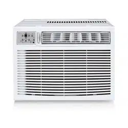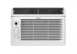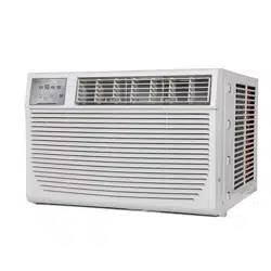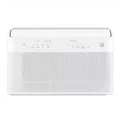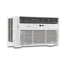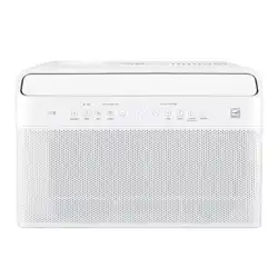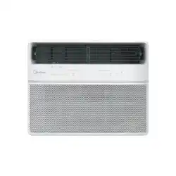
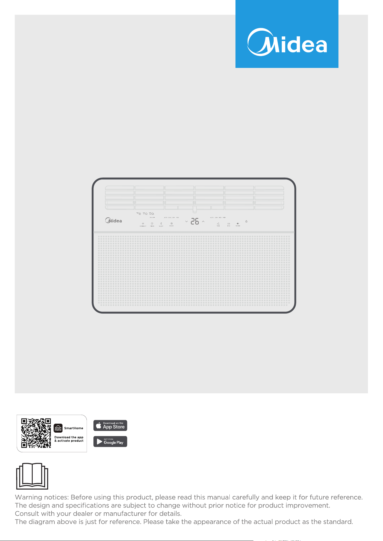
WINDOW TYPE ROOM AIR CONDITIONER
USER MANUAL
MAW18RA1CWT

THANK YOU LETTER
Thank you for choosing Midea! Before using your new Midea product, please read
this manual thoroughly to ensure that you know how to operate the features and
functions that your new air conditioner offers in a safe way.
CONTENTS
THANK YOU LETTER ....................................................................................... 2
IMPORTANT SAFETY INSTRUCTIONS .......................................................... 3
INSTALLATION INSTRUCTIONS ...................................................................14
NORMAL SOUNDS .........................................................................................24
AIR CONDITIONER FEATURES ....................................................................25
CARE AND CLEANING ..................................................................................36
TROUBLESHOOTING TIPS ........................................................................... 37
CONNECTION INSTRUCTIONS ....................................................................39
WARRANTY .................................................................................................45
Page 3
Important Safety
Instructions
Important Safety Instructions
READ THIS MANUAL
Inside you will find many helpful hints on how to use and maintain your air condi-
tioner properly. Just a little preventive care on your part can save you a great deal
of time and money over the life of your air conditioner. You'll find many answers to
common problems in the chart of troubleshooting tips. If you review our chart of
Troubleshooting Tips first, you may not need to call for service at all.
To prevent injury to the user or other people and property damage, the following
instructions must be followed. Incorrect operation due to ignoring of instructions
may cause harm or damage. The seriousness is classified by the following indica-
tions.
WARNING
This symbol indicates the possibility of death or serious injury .
CAUTION
This symbol indicates the possibility of injury or damage to property.
Never do this.
Always do this.
WARNING
• Plug in power plug properly. Otherwise, it may cause electric shock or fire due
to excess heat generation. Do not operate or stop the unit by inserting or pull-
ing out the power plug. It may cause electric shock or fire due to heat gener-
ation. Do not damage or use an unspecified power cord. It may cause electric
shock or fire. If the power cord is damaged, it must be replaced by the manu-
facturer or an authorised service centre or a similarly qualified person in order
to avoid a hazard.
• Always install circuit breaker and a dedicated power circuit. Incorrect instal-
lation may cause fire and electric shock. Do not operate with wet hands or in
damp environment. It may cause electric shock. Do not direct airflow at room
occupants only. This could damage your health.
• Always ensure effective grounding. Incorrect grounding may cause electric
shock. Do not allow water to run into electric parts. It may cause failure of ma-
chine of electric shock. Do not modify power cord length or share the outlet
with other appliances. It may cause electric shock or fire due to heat genera-
tion.
• Unplug the unit if strange sounds, smell, or smoke comes from it. It may cause
fire and electric shock. Do not use the socket if it is loose or damaged. It may
cause fire and electric shock. Do not open the unit during operation. It may
cause electric shock.
• Keep firearms away. It may cause fire. Do not use the power cord close to heat-
ing appliances. It may cause fire and electric shock. Do not use the power cord
near flammable gas or combustibles, such as gasoline, benzene, thinner, etc. It
Page 4
Important Safety
Instructions
may cause an explosion or fire.
• Ventilate room before operating air conditioner if there is a gas leakage from
another appliance. It may cause explosion, fire and, burns. Do not disassemble
or modify unit. It may cause failure and electric shock.
CAUTION
• When the air filter is to be removed, do not touch the metal parts of the unit. It
may cause an injury. Do not put a pet or house plant where it will be exposed to
direct air flow. This could injure the pet or plant. Ventilate the room well when
used together with a stove, etc. An oxygen shortage may occur.
• Do not use strong detergent such as wax or thinner but use a soft cloth. Ap-
pearance may be deteriorated due to change of product color or scratching
of its surface. Do not clean the air conditioner with water. Water may enter the
unit and degrade the insulation. It may cause an electric shock. Do not use for
special purposes. Do not use this air conditioner to preserve precision devices,
food, pets, plants, and art objects. It may cause deterioration of quality, etc.
• Stop operation and close the window in storm or hurricane. Operation with
windows opened may cause wetting of indoor and soaking of household furni-
ture. When the unit is to be cleaned, switch off, and turn off the circuit breaker.
Do not clean unit when power is on as it may cause fire and electric shock, it
may cause an injury.
• Ensure that the installation bracket of the outdoor appliance is not damaged
due to prolonged exposure. If bracket is damaged, there is concern of damage
due to falling of unit.
• Always insert the filters securely. Clean filter once every two weeks. Operation
without filters may cause failure. Hold the plug by the head of the power plug
when taking it out. It may cause electric shock and damage. Turn off the main
power switch when not using the unit for a long time. It may cause failure of
product or fire.
• Do not place obstacles around air-inlets or inside of air-outlet. It may cause
failure of appliance or accident. Do not place heavy object on the power cord
and ensure that the cord is not compressed. There is danger of fire or electric
shock. Do not drink water drained from air conditioner. It contains contami-
nants and could make you sick.
• Use caution when unpacking and installing. Sharp edges could cause injury.
• If water enters the unit, turn the unit off at the power outlet and switch off the
circuit breaker. Isolate supply by taking the power-plug out and contact a qual-
ified service technician.
CAUTION
• This appliance is not intended for use by persons (including children) with re-
duced physical, sensory or mental capabilities or lack of experience and knowl-
edge, unless they have been given supervision or instruction concerning use of
the appliance by a person responsible for their safety.
• Children should be supervised to ensure that they do not play with the
appliance.
• If the supply cord is damaged, it must be replaced by the manufacturer, its ser-
vice agent or similarly qualified persons in order to avoid a hazard.
• The appliance shall be installed in accordance with national wiring regulations.
Page 5
Important Safety
Instructions
• Do not operate your air conditioner in a wet room such as a bathroom or laun-
dry room.
• The appliance with electric heater shall have at least 1meter space to the com-
bustible materials.
• Contact the authorised service technician for repair or maintenance of this unit.
• Contact the authorised installer for installation of this unit.
• Do not operate the louvers with your hands, it may cause an injury.
NOTE:
The power supply cord with this air conditioner contains a current detection device
designed to reduce the risk of fire. Please refer to the section Operation of Current
Device for details. In the event that the power supply cord is damaged, it cannot be
repaired-it must be replaced with a cord from the Product Manufacturer.
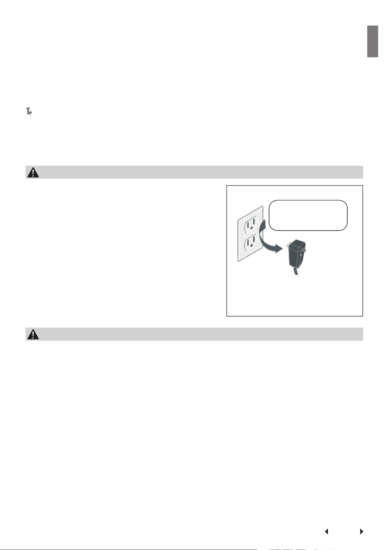
WARNING
Avoid fire hazard or electric shock. Do not use
an extension cord or an adaptor plug. Do not re-
move any prong from the power cord.
WARNING
For Your Safety
Do not store or use gasoline or other flammable vapors and liquids in the vicinity
of this or any other appliance.
Prevent Accidents
To reduce the risk of fire, electrical shock, or injury to persons when using your air
conditioner, follow basic precautions, including the following:
• Be sure the electrical service is adequate for the model you have chosen. This
information can be found on the serial plate, which is located on the side of the
the cabinet and behind the grille.
• If the air conditioner is to be installed in a window, you will probably want
to clean both sides of the glass first. If the window is a triple-track type with
screen panel included, remove the screen completely before installation.
• Be sure the air conditioner has been securely and correctly installed according
to the installation instructions in this manual. Save this manual for possible fu-
ture use in removing or installing this unit. When handling the air conditioner,
be careful to avoid cuts from sharp metal fins on front and rear coils.
Grounding type wall receptacle
Power supply cord with 3-prong
grounding plug and current
detection device.
Do not, under any
circumstances, cut,
remove, or bypass
the grounding prongs.
Page 6
Important Safety
Instructions
Electrical Information
The complete electrical rating of your new room air conditioner is stated on the
serial plate. Refer to the rating when checking the electrical requirements.
• Be sure the air conditioner is properly grounded. To minimize shock and fire
hazards, proper grounding is important. The power cord is equipped with a
three-prong grounding plug for protection against shock hazards.
• Your air conditioner must be used in a properly grounded wall receptacle. If the
wall receptacle you intend to use is not adequately grounded or protected by a
time delay fuse or circuit breaker, have a qualified electrician install the proper
receptacle. Ensure the receptacle is accessible after the unit installation.
• Do not run air conditioner without side protective cover in place. This could
result in mechanical damage within the air conditioner.
• Do not use an extension cord or an adapter plug.
Operation of Current Device
(Applicable to the unit adopts current detection device only )
The power supply cord contains a current device that senses damage to the power
cord. To test your power supply cord do the following:
1. Plug in the Air Conditioner.
2. The power supply cord will have TWO buttons on the plug head. Press the
TEST button, you will notice a click as the RESET button pops out.
3. Press the RESET button, again you will notice a click as the button engages.
4. The power supply cord is now supplying electricity to the unit. (On some prod-
ucts this is also indicated by a light on the plug head.)
NOTE:
• Do not use this device to turn the unit on or off.
• Always make sure the RESET button is pushed in for correct operation.
• The power supply must be replaced if it fails reset when either the TEST button
is pushed, or it cannot be reset. A new one can be obtained from the product
manufacturer.
• If power supply cord is damaged, it cannot be repaired. It MUST be replaced by
one obtained from the product manufacturer.
NOTE:This air conditioner is designed to be operated under condition as follows:
Cooling operation
Outdoor temp:
64-109
O
F/18-43
O
C (64-125
O
F/18-52
O
C for special tropical mod-
els)
Indoor temp: 62-90
O
F/17-32
O
C
Heating operation
Outdoor temp: 23-76
O
F/-5-24
O
C
Indoor temp: 32-80
O
F/0-27
O
C
Note: Performance may be reduced outside of these operating temperatures.
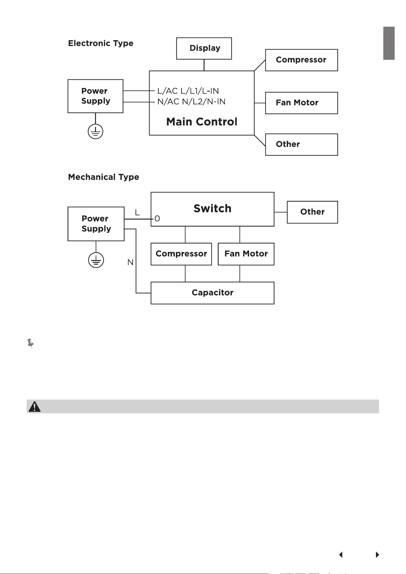
Electronic Work
WARNING:
BEFORE PERFORMING ANY ELECTRICAL OR WIRING WORK, TURN
OFF THE MAIN POWER TO THE SYSTEM.
Page 7
Important Safety
Instructions
NOTICE:
Please strictly follow the wiring label attached to the machine for all wiring connec-
tions. The wiring diagram may vary for different unit. Please refer to the wiring dia-
gram on the machine you have purchased. The above wiring diagram is a simplified
version for preliminary illustration purposes only.
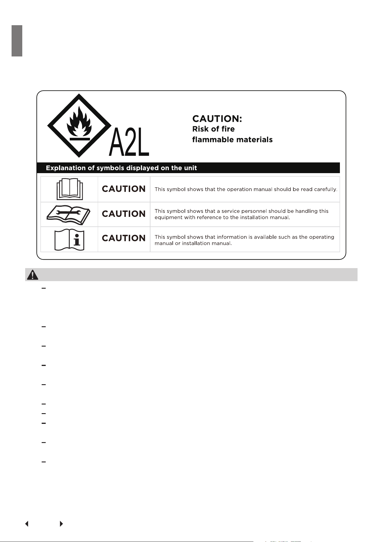
WARNING for Using R32 Refrigerant
• Do not use means to accelerate the defrosting process or to clean, other than
those recommended by the manufacturer.
• The appliance shall be stored in a room without continuously operating ignition
sources (for example: open flames, an operating gas appliance or an operating
electric heater).
• Do not pierce or burn.
• Be aware that the refrigerants may not contain an odour.
• Appliance should be installed, operated and stored in a room with a floor area
according to the amount of refrigerant to be charged. For specific information
on the type of gas and the amount, please refer to the relevant label on the unit
itself. When there are differences between the label and the manual on the Min.
room area description, the description on label shall prevail.
• Appliance shall be installed, operated and stored in a room with a floor area
Page 8
Important Safety
Instructions
larger than 4 m². Appliance shall not be installed in an unventilated space, if
that space is smaller than 4 m².
• No open fire or device like switch which may generate spark/arcing shall be
around appliance to avoid causing ignition of the flammable refrigerant used.
Please follow the instructions carefully when storing or maintaining the appli-
ance to prevent mechanical damage from occurring.
WARNING for Using R32 Refrigerant
Servicing shall only be performed as recommended by the equipment man-
ufacturer. Maintenance and repair requiring the assistance of other skilled
personnel shall be carried out under the supervision of the person compe-
tent in the use of flammable refrigerants.
DO NOT modify the length of the power cord or use an extension cord to
power the unit.
DO NOT share a single outlet with other electrical appliances. Improper
power supply can cause fire or electrical shock.
Please follow the instruction carefully to handle, install, clear, service the
appliance to avoid any damage or hazard.
When maintaining or disposing the appliance, the refrigerant shall be recov-
ered properly, shall not discharge to air directly.
Compliance with national gas regulations shall be observed.
Keep ventilation openings clear of obstruction.
The appliance shall be stored so as to prevent mechanical damage from
occurring.
A warning that the appliance shall be stored in a well-ventilated area where
the room size corresponds to the room area as specified for operation.
Any person who is involved with working on or breaking into a refrigerant
circuit should hold a current valid certificate from an industry-accredited
assessment authority, which authorises their competence to handle refriger-
ants safely in accordance with an industry recognised assessment specifica-
tion. All training shall follow the ANNEX HH requirements of UL 60335-2-40
4th Edition. Examples for such working procedures are:
Page 9
Important Safety
Instructions
• breaking into the refrigerating circuit;
• opening of sealed components;
• opening of ventilated enclosures.
1. Transport of equipment containing flammable refrigerants
See transport regulations.
2. Marking of equipment using signs
See local regulations.
3. Disposal of equipment using flammable refrigerants
See national regulations.
4. Storage of equipment/appliances
The storage of the appliance should be in accordance with the applicable regu-
lations or instructions, whichever is more stringent.
5. Storage of packed (unsold) equipment
Storage package protection should be constructed such that mechanical dam-
age to the equipment inside the package will not cause a leak of the refrigerant
charge. The maximum number of pieces of equipment permitted to be stored
together will be determined by local regulations.
6. Information on servicing
1) Checks to the area
Prior to beginning work on systems containing flammable refrigerants, safe-
ty checks are necessary to ensure that the risk of ignition is minimised. For
repair to the refrigerating system, the following precautions shall be com-
plied with prior to conducting work on the system.
2) Work procedure
Work shall be undertaken under a controlled procedure so as to minimise
the risk of a flammable gas or vapour being present while the work is being
performed.
3) General work area
All maintenance staff and others working in the local area shall be instruct-
ed on the nature of work being carried out. Work in confined spaces shall
be avoided. The area around the workspace shall be sectioned off. Ensure
that the conditions within the area have been made safe by control of flam-
mable material.
4) Checking for presence of refrigerant
The area shall be checked with an appropriate refrigerating detector prior
to and during work, to ensure the technician is aware of potentially flam-
mable atmospheres. Ensure that the leak detection equipment being used
is suitable for use with flammable refrigerants, i.e. non-sparking, adequately
sealed or intrinsically safe.
5) Presence of fire extinguisher
If any hot work is to be conducted on the refrigeration equipment or any
associated parts, appropriate fire extinguishing equipment shall be available
to hand. Have a dry powder or CO2 fire extinguisher adjacent to the charg-
ing area.
Page 10
Important Safety
Instructions
6) No ignition sources
No person carrying out work in relation to a refrigerating system which in-
volves exposing any pipe work that contains or has contained flammable re-
frigerant shall use any sources of ignition in such a manner that it may lead
to the risk of fire or explosion. All possible ignition sources, including ciga-
rette smoking, should be kept sufficiently far away from the site of installa-
tion, repairing, removing and disposal, during which flammable refrigerant
can possibly be released to the surrounding space. Prior to work taking
place, the area around the equipment is to be surveyed to make sure that
there are no flammable hazards or ignition risks. No Smoking signs shall be
displayed.
7) Ventilated area
Ensure that the area is in the open or that it is adequately ventilated before
breaking into the system or conducting any hot work. A degree of ventila-
tion shall continue during the period that the work is carried out. The venti-
lation should safely disperse any released refrigerant and preferably expel it
externally into the atmosphere.
8) Checks to the refrigerating equipment
Where electrical components are being changed, they shall be fit for the
purpose and to the correct specifications. At all times the manufacturer's
maintenance and service guidelines shall be followed. If in doubt consult the
manufacturer's technical department for assistance. The following checks
shall be applied to installations using flammable refrigerants: the actual re-
frigerant charge is in accordance with the room size within which the refrig-
erant containing parts are installed; the ventilation machinery and outlets
are operating adequately and are not obstructed; if an indirect refrigerating
circuit is being used, the secondary circuit shall be checked for the pres-
ence of refrigerant; marking to the equipment continues to be visible and
legible. Markings and signs that are illegible shall be corrected; and refriger-
ating pipe or components are installed in a position where they are unlikely
to be exposed to any substance which may corrode refrigerant containing
components, unless the components are constructed of materials which are
inherently resistant to being corroded or are suitably protected against be-
ing so corroded.
9) Checks to electrical devices
Repair and maintenance to electrical components shall include initial safety
checks and component inspection procedures. If a fault exists that could
compromise safety, then no electrical supply shall be connected to the cir-
cuit until it is satisfactorily dealt with. If the fault cannot be corrected im-
mediately but it is necessary to continue operation, an adequate temporary
solution shall be used. This shall be reported to the owner of the equipment
so all parties are advised. Initial safety checks shall include: That capacitors
are discharged: this shall be done in a safe manner to avoid possibility of
sparking; that there no live electrical components and wiring are exposed
while charging, recovering or purging the system; that there is continuity of
earth bonding.
7. Sealed electrical components shall be replaced.
8. Intrinsically safe components must be replaced.
Page 11
Important Safety
Instructions
9. Cabling
Check that cabling will not be subject to wear, corrosion, excessive pressure,
vibration, sharp edges or any other adverse environmental effects. The check
shall also take into account the effects of aging or continual vibration from
sources such as compressors or fans.
10. Detection of flammable refrigerants
Under no circumstances shall potential sources of ignition be used in the
searching for or detection of refrigerant leaks. A halide torch (or any other
detector using a naked flame) shall not be used. The following leak detection
methods are deemed acceptable for systems containing flammable refriger-
ants. Electronic leak detectors shall be used to detect flammable refrigerants,
but the sensitivity may not be adequate, or may need re-calibration. (Detection
equipment shall be calibrated in a refrigerant-free area.) Ensure that the detec-
tor is not a potential source of ignition and is suitable for the refrigerant used.
Leak detection equipment shall be set at a percentage of the LFL of the refrig-
erant and shall be calibrated to the refrigerant employed and the appropriate
percentage of gas (25 % maximum) is confirmed. Leak detection fluids are suit-
able for use with most refrigerants but the use of detergents containing chlo-
rine shall be avoided as the chlorine may react with the refrigerant and corrode
the copper pipe-work. If a leak is suspected, all naked flames shall be removed/
extinguished. If a leakage of refrigerant is found which requires brazing, all of
the refrigerant shall be recovered from the system, or isolated (by means of
shut off valves) in a part of the system remote from the leak. Removal of refrig-
erant shall be according to Removal and evacuation.
11. Removal and evacuation
When breaking into the refrigerant circuit to make repairs-or for any other pur-
pose - conventional procedures shall be used. However, for flammable refriger-
ants it is important that best practice be followed, since flammability is a con-
sideration. The following procedure shall be adhered to:
Safely remove refrigerant following local and national regulations;
Evacuate;
Purge the circuit with inert gas (optional for A2L);
Evacuate (optional for A2L);
Continuously flush or purge with inert gas when using flame to open circuit;
and
Open the circuit.
The refrigerant charge shall be recovered into the correct recovery cylinders if
venting is not allowed by local and national codes. For appliances containing
flammable refrigerants, the system shall be purged with oxygen-free nitrogen
to render the appliance safe for flammable refrigerants. This process might
need to be repeated several times. Compressed air or oxygen shall not be used
for purging refrigerant systems.
For appliances containing flammable refrigerants, refrigerants purging shall be
achieved by breaking the vacuum in the system with oxygen-free nitrogen and
continuing to fill until the working pressure is achieved, then venting to atmos-
phere, and finally pulling down to a vacuum (optional for A2L). This process
shall be repeated until no refrigerant is within the system (optional for A2L).
When the final oxygen-free nitrogen charge is used. the system shall be vented
down to atmospheric pressure to enable work to take place. The outlet for the
Page 12
Important Safety
Instructions
vacuum pump shall not be close to any potential ignition sources, and ventila-
tion shall be available.
12. Charging procedures
In addition to conventional charging procedures, the following requirements
shall be followed. Ensure that contamination of different refrigerants does not
occur when using charging equipment. Hoses or lines shall be as short as pos-
sible to minimise the amount of refrigerant contained in them. Cylinders shall
be kept in an appropriate position according to the instructions. Ensure that the
refrigeration system is earthed prior to charging the system with refrigerant.
Label the system when charging is complete (if not already). Extreme care shall
be taken not to overfill the refrigeration system. Prior to recharging the system
it shall be pressure tested with OFN. The system shall be leak tested on com-
pletion of charging but prior to commissioning. A follow up leak test shall be
carried out prior to leaving the site.
13. Decommissioning
Before carrying out this procedure, it is essential that the technician is com-
pletely familiar with the equipment and all its detail. It is recommended good
practice that all refrigerants are recovered safely. Prior to the task being carried
out, an oil and refrigerant sample shall be taken in case analysis is required pri-
or to re-use of reclaimed refrigerant. It is essential that electrical power is avail-
able before the task is commenced.
a) Become familiar with the equipment and its operation.
b) Isolate system electrically.
c) Before attempting the procedure ensure that: Mechanical handling equip-
ment is available, if required, for handling refrigerant cylinders; all personal
protective equipment is available and being used correctly; the recovery
process is supervised at all times by a competent person; recovery equip-
ment and cylinders conform to the appropriate standards.
d) Pump down refrigerant system, if possible.
e) If a vacuum is not possible, make a manifold so that refrigerant can be re-
moved from various parts of the system.
f) Make sure that cylinder is situated on the scales before recovery takes
place.
g) Start the recovery machine and operate in accordance with manufacturer's
instructions.
h) Do not overfill cylinders. (No more than 80 % volume liquid charge).
i) Do not exceed the maximum working pressure of the cylinder, even tempo-
rarily.
j) When the cylinders have been filled correctly and the process complet-
ed, make sure that the cylinders and the equipment are removed from site
promptly and all isolation valves on the equipment are closed off.
k) Recovered refrigerant shall not be charged into another refrigeration sys-
tem unless it has been cleaned and checked.
14. Labelling
Equipment shall be labelled stating that it has been de-commissioned and emp-
tied of refrigerant. The label shall be dated and signed. Ensure that there are
labels on the equipment stating the equipment contains flammable refrigerant.
15. Recovery
Page 13
Important Safety
Instructions
When removing refrigerant from a system, either for servicing or decommis-
sioning, it is recommended good practice that all refrigerants are removed
safely. When transferring refrigerant into cylinders, ensure that only appropri-
ate refrigerant recovery cylinders are employed. Ensure that the correct num-
ber of cylinders for holding the total system charge is available. All cylinders
to be used are designated for the recovered refrigerant and labelled for that
refrigerant (i.e. special cylinders for the recovery of refrigerant). Cylinders shall
be complete with pressure relief valve and associated shut-off valves in good
working order. Empty recovery cylinders are evacuated and, if possible, cooled
before recovery occurs. The recovery equipment shall be in good working order
with a set of instructions concerning the equipment that is at hand and shall be
suitable for the recovery of the flammable refrigerant. If in doubt, the manufac-
turer should be consulted. In addition, a set of calibrated weighing scales shall
be available and in good working order. Hoses shall be complete with leak-free
disconnect couplings and in good condition.
The recovered refrigerant shall be processed according to local legislation in
the correct recovery cylinder, and the relevant waste transfer note arranged.
Do not mix refrigerants in recovery units and especially not in cylinders. If com-
pressors or compressor oils are to be removed, ensure that they have been
evacuated to an acceptable level to make certain that flammable refrigerant
does not remain within the lubricant. The compressor body shall not be heated
by an open flame or other ignition sources to accelerate this process. When oil
is drained from a system, it shall be carried out safely.
Page 14
Installation
Instructions
Installation Instructions
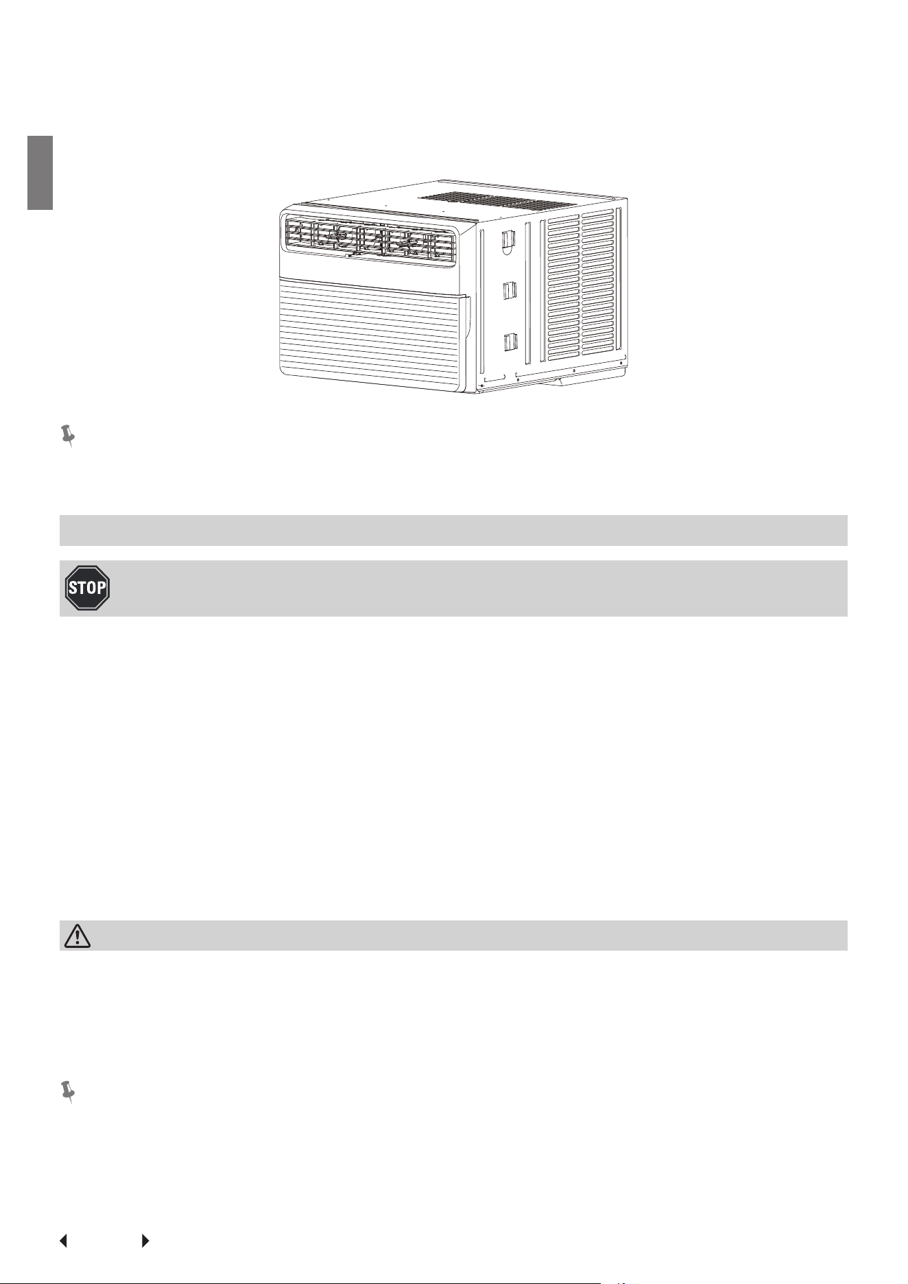
NOTE: The unit you purchased may be look like one of the followings:
NOTE:
All the illustrations in this manual are for explanation purpose only. The air condi-
tioner you have may be slightly different. The actual shape shall prevail.
Installation Instructions (for 15000 to 28500Btu/h)
BEFORE YOU BEGIN
Read these instructions completely and carefully.
IMPORTANT-Save these instructions for local inspector’s use.
IMPORTANT-Observe all governing codes and ordinances.
Note to Installer- Be sure to leave these instructions with the Consumer.
Note to Consumer- Keep these instructions for future reference.
Skill level- Installation of this appliance requires basic mechanical skills.
Completion time- Approximately 1 hour. We recommend that two people install this
product.
Proper installation is the responsibility of the installer.
Product failure due to improper installation is not covered under the Warranty.
You MUST use all supplied parts and use proper installation procedures as de-
scribed in these instructions when installing this air conditioner.
CAUTION
Do not, under any circumstances, cut or remove the third (ground) prong from the
power cord. Do not change the plug on the power cord of the air conditioner.
Aluminum house wiring may present special problems- consult a qualified electri-
cian. When handling unit, be careful to avoid cuts from sharp metal edges and alu-
minum fins on front and rear coils.
NOTE:
Save Carton and these Installation Instructions for future reference. The carton is
the best way to store unit during winter, or when not in use.
Page 15
Installation
Instructions
Preliminary Instructions
Do the following before starting to install unit.
See illustrations below.
Check dimensions of your unit to determine
model type:
Unit Height: 18 ⅝
"
17 ⅝
"
Unit Width: 26 ½
"
23 ⅝
"
Min. Window Opening: 19 ½
"
18 ½
"
Min. Window Width: 31" 28"
Max. Window Width: 42" 40 ½
"
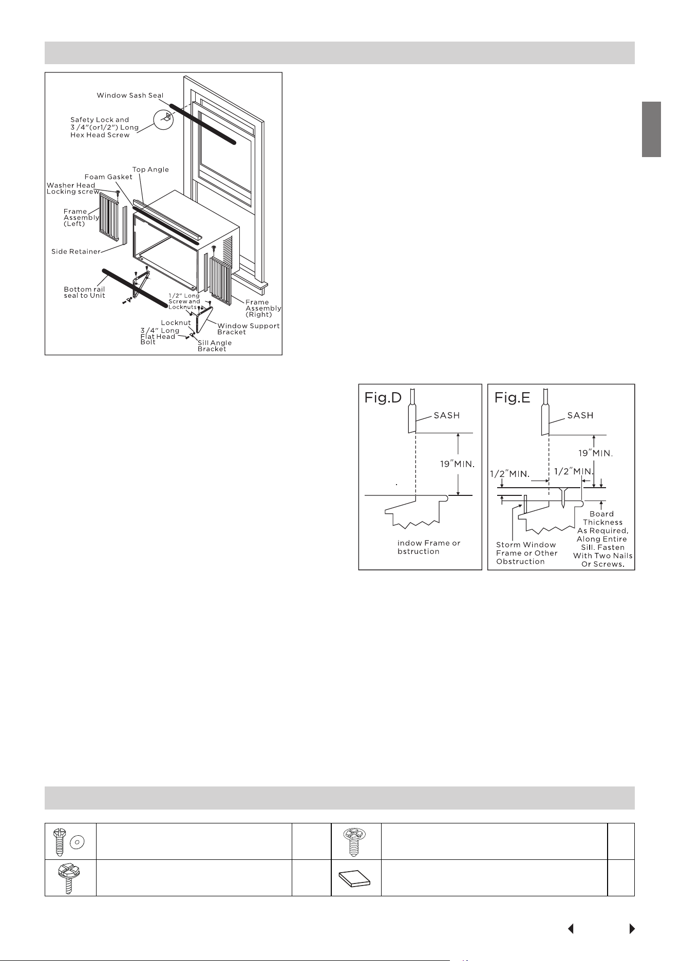
1. Check window opening size-- the
mounting parts furnished with this air
conditioner are made to install in a
wooden sill double-hung window. The
standard parts are for window dimen-
sions listed above. Open sash to a min-
imum of 19 inches(483mm). See Fig.D.
2. Check condition of window-- all wood
parts of window must be in good
shape and able to firmly hold the
needed screws. If not, make repairs
before installing unit.
3. Check your storm windows-- if your storm window frame does not allow the
clearance required, correct by adding a piece of wood as shown in Fig.E,or by
removing storm window while room air conditioner is being installed.
4. Check for anything that could block airflow-- check area outside of window
for things such as shrubs, trees, or awnings. Inside, be sure furniture, drapes, or
blinds will not stop proper airflow.
5. Check the available electrical service--Power supply must be the same as that
shown on the unit serial nameplate. Power cord is 48 inches long. Be sure you
have an outlet near.
6. Carefully unpack air conditioner-- Remove all packing material. Protect floor or
carpet from damage. Two people should be used to move and install unit.
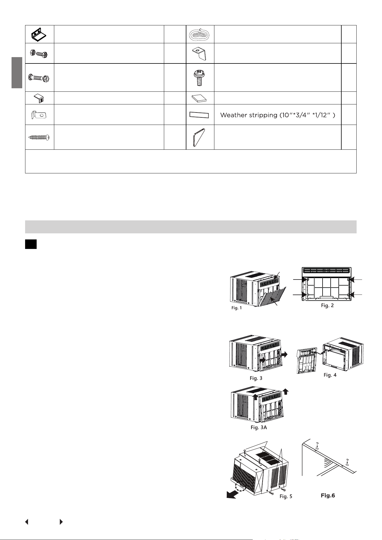
Hardware(Packed with the unit)
7/16 inch Locking screw and
Flat washer for window panels
2ea.
Long hex-head locking screw for top
angle, side retainer 5/16 inch Long
10
3/4 ( or 1/2)inch Long Hex-head
Screw
7 Foam insert 2
Page 16
Installation
Instructions
Safety Lock 1 Window sash seal foam 1
1/2 inch Long screw and Lock-
nut
4ea.
Safety Lock (for Vinyl-Clad window)
(on some models)
2
3/4 inch Long Flat Head Bolt
and Locknut
2ea.
Locking screw #10X 1/4 Phillips pan-
head screws (for Vinyl-Clad window)
(on some models)
2
Sill Angle Bracket 2 R1 hardware 2
Lock Frame (For Wooden win-
dows)(on some models)
2 5
3/4 inch Long Screw(on some
models)
2 Sill angle bracket (on some models) 2
NOTE: R1 hardware and Weather stripping is only for Energy star models
(for≥15000Btu/h models only).
Tools Required
A large flat blade screwdriver; Tape measure; Adjustable wrench or pliers; Pencil;
Level Socket wrenches; Phillips Screwdriver.
A. Window Mounting
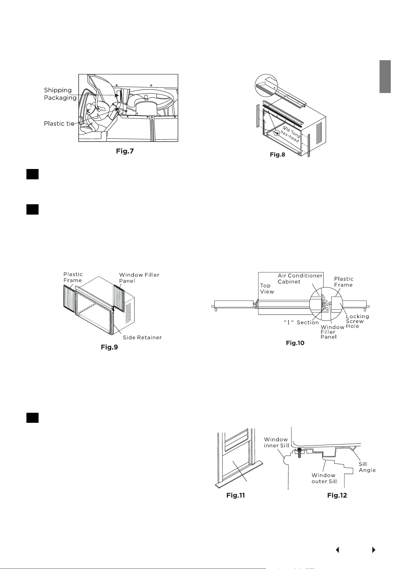
1 Remove Air Conditioner from Cabinet
NOTE: Remove any packaging material from cabinet exterior.
1. Pull down front grille and remove filter.
(See Fig.1).
2. Lift front grille upwards and place to one
side.
3. Locate the four front screws and remove.
These screws will be needed to re-install
the front panel (see Fig.2).
4. Push metal cabinet side to release plastic
tabs on each side of front panel
(see Fig.3).
5. Gently lift front panel off unit(see Fig.3A).
6. Disconnect the connector plug of the
display panel from the unit and place
front panel to one side(see Fig.4).
7. Remove shipping screws from top of unit
and also on the side by the base if
installed(see Fig.5).
8. Hold the cabinet while pulling on the base
pan handle, and carefully remove the unit.
9. Add two foam inserts to holes in top of
cabinet where shipping screws were
removed from (see Fig.6).
Front Panel
Front Grille
Shipping
Screws
Page 17
Installation
Instructions
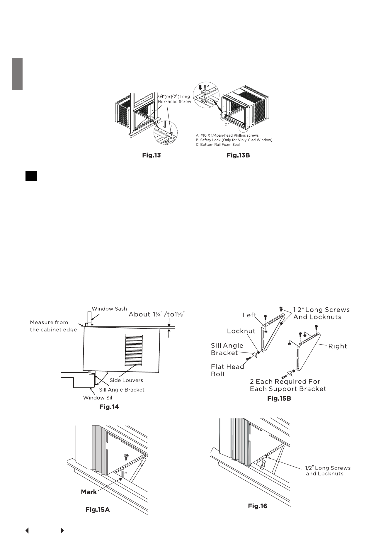
10. Your unit may come with internal packaging. This packaging must be re-
moved prior to installing the air conditioner back into the cabinet.
(see Fig.7)
2 Install top angle and side Bracket
1. Attach foam gasket to top angle above holes as shown in Fig.6.
2. Install top angle and side retainers to cabinet as shown in Fig.8(10 screws).
3 Assemble Window Filler Panels
1. Place cabinet on floor, a bench, or a table.
2. Slide "I " section of window filler panel into side retainer on the side of the
cabinet (see Fig.9 & Fig.10).
Do both sides.
3. Insert top and bottom legs of window filler panel frame into channel in the
top angle and bottom rail. Do both sides.
4. Insert washer head locking 7/16" screws (2) into holes in top leg of filler
panel frame (see step 6). Do not totally tighten. Allow leg to slide freely.
Screws will be tightened after section 6.
4 Place Cabinet in window
1. Open window and mark center of
window inner sill as shown(Fig.11).
2. Place cabinet in window with bot-
tom sill angle firmly seated over
window sill as shown. Bring window
down temporarily behind top angle
to hold cabinet in place(Fig.12).
3. Shift cabinet left or right as needed
to line up center of cabinet on center line marked on inner sill.
4. For wooden window: Fasten cabinet to window inner sill with two screws
into holes (Fig.13) (You may wish to pre-drill pilot holes).
Page 18
Installation
Instructions
For Vinyl-Clad window: Place two safety locks into the holes located in the
bottom of the cabinet and drive two #10X1/4" pan-head Phillips locking
screws through the safety locks into the cabinet as shown (Fig.13B).
5. Remove protective strip from adhesive side of Bottom Rail Foam Seal.Apply
Seal over screws fastening bottom rail to window inner sill.
5 Install Support Bracket
1. Hold each support bracket flush against outside of sill, and tight to bottom
of cabinet as shown in Fig.15A.Mark brackets at top level of sill and remove.
2. Assemble sill angle bracket to support brackets at the marked position
(Fig.15B). Hand tighten, but allow for any changes later.
NOTE: Check that air conditioner is tilted back about 1¼
"
to 1⅝
"
(tilted about 3°
to 4°downward to the outside). After proper installation, condensate should
not drain from the overflow drain hole during normal use,correct the slope oth-
erwise (Fig .14).
3. Install support brackets(with sill angle brackets attached) to correct hole in
bottom of cabinet as shown in Fig.16.
4. Tighten all 6 bolts securely.
Page 19
Installation
Instructions
6 Extend Window Filler Panels
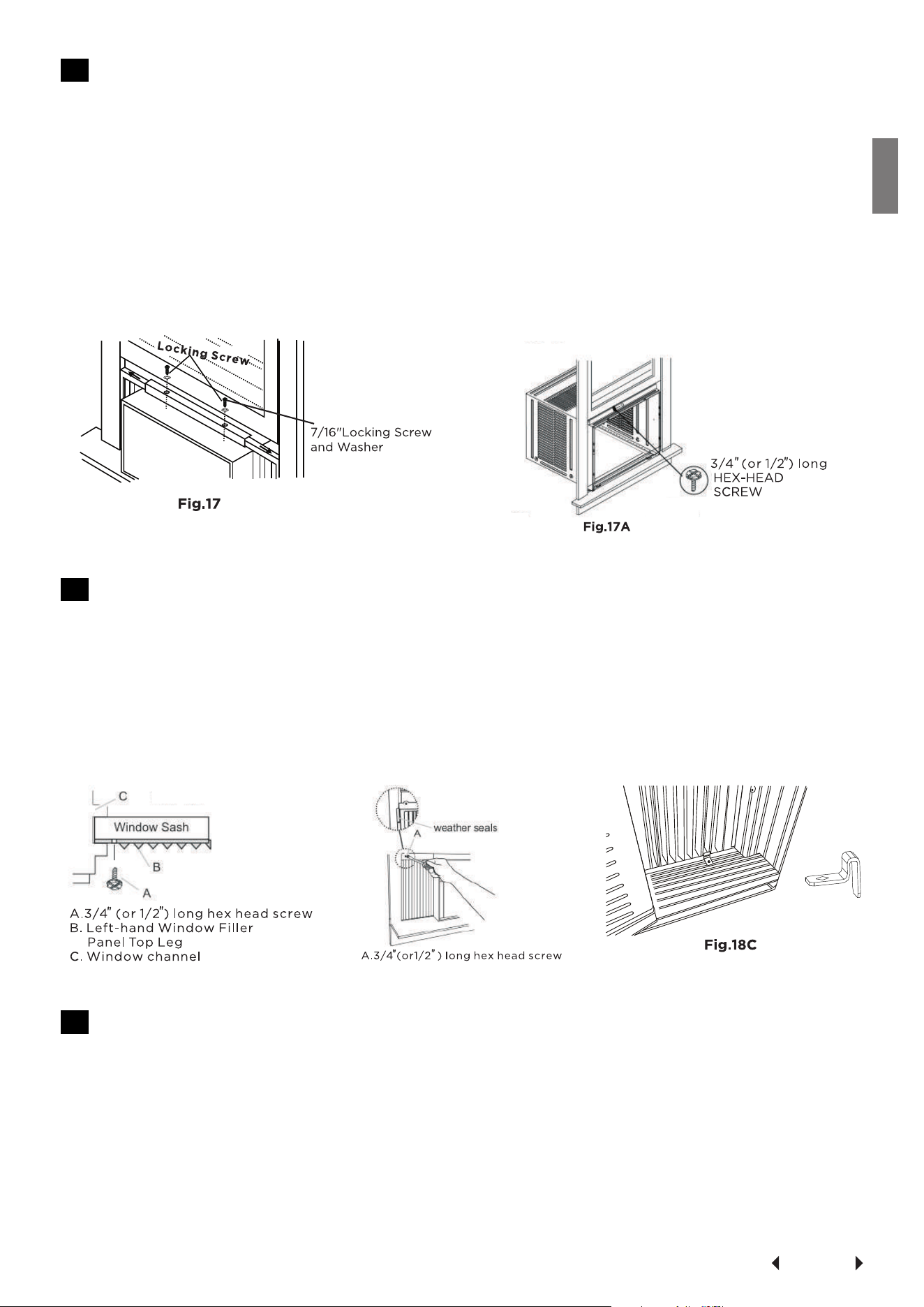
1. Carefully raise window to expose filler panel locking screws. Loosen screws
so filler panels slide easily.
2. Extend panels to fill window opening completely. Tighten locking screws on
top (Fig.17).
3. Close window behind top angle.
4. Attach the top angle to window frame: Use a 3/32" drill bit to drill one hole
through the hole in the middle of top angle into the window frame, and
drive one 3/4 " (or 1/2 '') HEX-HEAD locking screw through hole in the mid-
dle of top angle into the window frame as shown (Fig.17A)
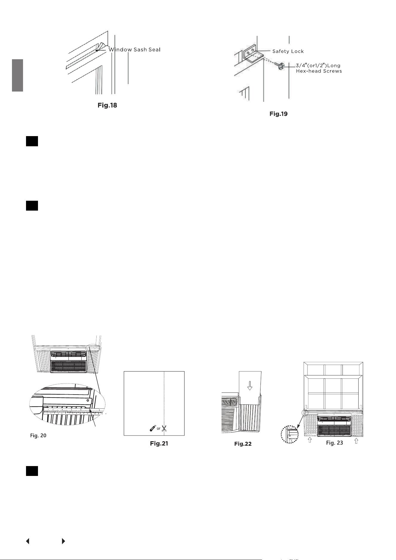
7 Attach Window Filler Panels to Window Frame
1. Extend the window filler panels out against the window frame.
2. Use a 1/8" drill bit to drill a starter hole through the hole in the top leg of
each window filler panel and into the window sash (Fig. 18A and Fig. 18B).
Connect with one 3/4"(or 1/2") long hex head screw.
3. Attach the Lock Frames to the window sill using two 3/4"(19mm) screws
(Fig.18C) (on some models)
Fig.18A
Fig.18B
8 Install Window Sash Seal and Safety Lock
1. Trim sash seal to fit window width. Insert into space between upper and
lower sashes (Fig.18).
2. Attach right angle safety lock (Fig. 19).
Page 20
Installation
Instructions
9 Install Chassis into Cabinet and Install Front to Unit
1. Lift air conditioner and carefully slide into cabinet leaving 6 inches protrud-
ing.
2. DO NOT push on controls or finned coils.
3. Be sure chassis is firmly seated towards rear of cabinet.
4. Installation of front is the reverse of removal outlined in Section 1.
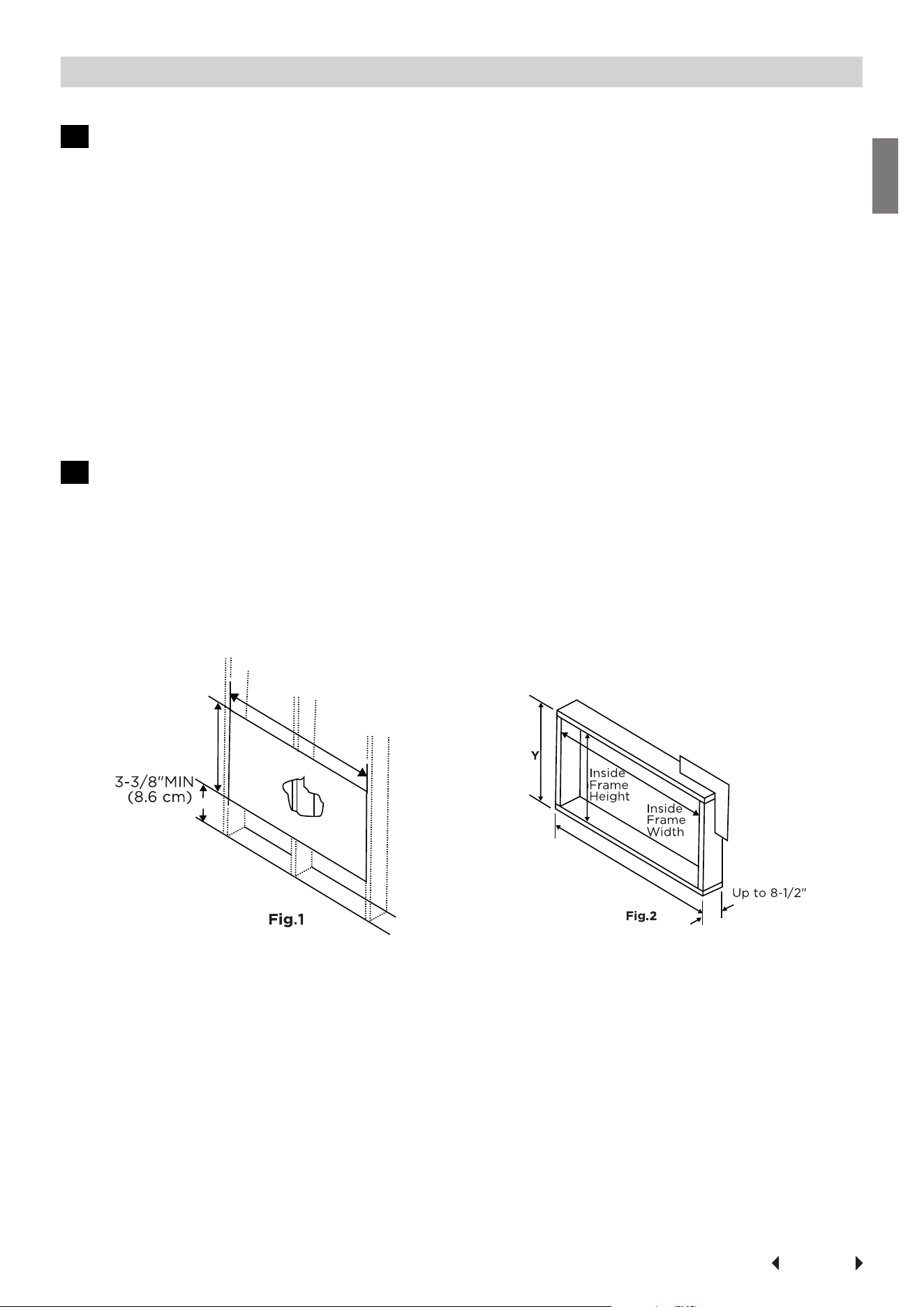
10 INSTALL R1 HARDWARE(only applicable to≥15000Btu/h Energy star models )
In order to minimize air leaks and ensure optimal insulation, it is necessary to
install the included R1 hardware to the side curtain. Follow the instructions be-
low.
Step 1. After the unit is installed to the window, measure the inner width of the
side curtain as shown (Fig.20).
Step 2. Remark a line on the provided R1 insulation panel according to a length
1/8"(3mm) less than the measured width in step 1, then cut the R1 insulation
panel along the line (Fig.21).
Step 3. Slide the R1 insulation panel into the side curtain, the side with pattern
should facing the indoor (Fig.22).
Step 4. Repeat on the other side.
11 INSTALL WEATHER STRIPPING (only applicable to Energy star models )
In order to minimize air leaks between the room air conditioner and the window
opening, trim the weather stripping with a proper length, peel off the protec-
tive backing and plug any gaps if needed (Fig.23).
Measure the inner width
of the side curtain
Page 21
Installation
Instructions
B. Thru-The-Wall Installation
NOTE: Consult local building codes prior to installation or a qualified carpenter.
1 Select Wall Location
The air conditioner has a slide-out chassis, so that it can be installed through an
outside wall as specified below: Max. Wall thickness: 12" or 10" IMPORTANT: Side
louvers must never be blocked.
NOTE:All parts needed for Thru-The-Wall Installation are provided, except a wood
frame, shims, and 10 wood screws(#10-1" long minimum). Select a wall surface that:
(1) does not support major structural loads such as the frame construction at ends
of windows, and under truss-bearing points, etc.
(2) does not have plumbing or wiring inside.
(3) is near existing electrical outlets or where another outlet can be installed.
(4) is not blocked to the area to be cooled.
(5) allows unblocked airflow from rear sides and end(outside) of installed air condi-
tioner.
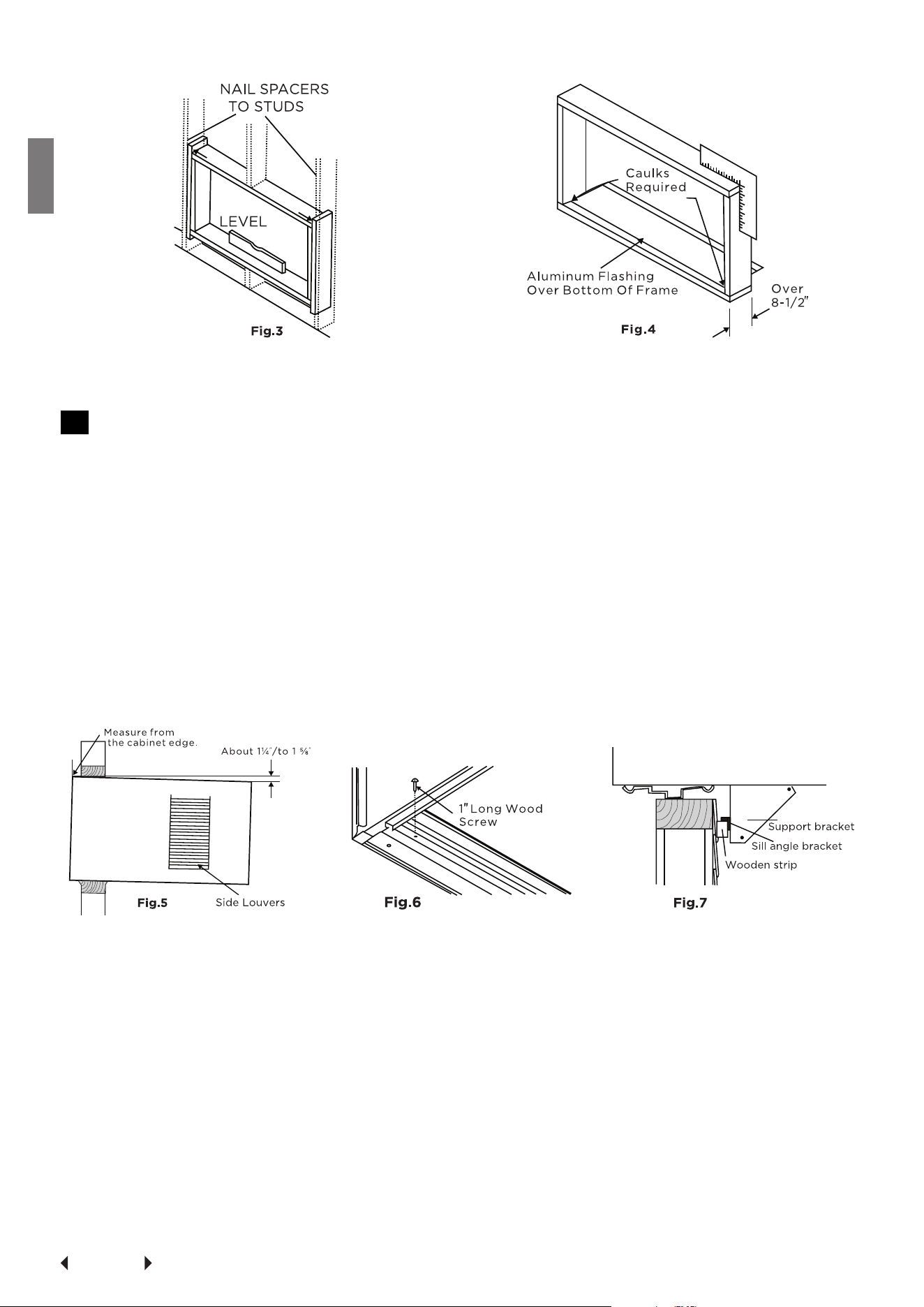
2 Prepare Wall
(1) Prepare wall in frame construction (including brick and stucco veneer). Work-
ing from inside the room, find wall stud nearest the center of area where air
conditioner will be installed (by sounding wall or by magnetically finding nails).
(2) Cut or knock out a hole on each side of center stud.
(3) Measure between inside edges of every other stud as shown in Fig.1.
Carefully measure and cut an opening with the following dimensions depending on
your model. See Fig.1 and Fig.2.
WIDTH "X"= inside model width plus twice the thickness of framing material used.
HEIGHT ''Y"= inside model height plus twice the thickness of framing material used.
Inside Frame Height: 18-7/8"(47.9cm) or 18"(45.7cm)
Inside Frame Width: 26-3/4"(67.9cm) or 23-7/8"(60.6cm)
(4) Build a wooden frame with the INSIDE dimensions of your model listed above.
(Remember to measure twice). Frame depth should be the same as wall thick-
ness. Fill in the space from the opening to the studs with wood spacers, as
shown.
(5) Nail frame to spacers to spacers with front flush with drywall.
Page 22
Installation
Instructions
NOTE: If wall thickness is 8-1/2 " or more, add aluminum flashing over bottom of
frame opening to assure no water can enter area between inner and outer wall.
3 Prepare and Install Cabinet
(1) Slide chassis from cabinet. Refer back to Step one of Window Mounting.
(2) Place cabinet into opening with bottom rail resting firmly on bottom board of
wooden frame.
(3) Position cabinet to achieve proper slope for water removal.(See Fig.5 below.)
(4) Secure bottom rail to wood frame with two large wood screws 1"(2.5cm) long
using the two holes in the bottom of the channel resting on frame.(See Fig.6 ).
NOTE: Check that air conditioner is tilted back about 1 ¼" to 1 ⅝"(tilted about 3°to
4° downward to the outside). After proper installation, condensate should not
drain from the overflow drain hole during normal use, correct the slope otherwise
(Fig.14).
Refer to Step 5 of Window Mounting for assembly of support brackets. A wooden
strip nailed to the outside wall should be used in conjunction with sill support angle
brackets.
(5) Screw or nail cabinet wooden frame using shims if frame is oversized to elimi-
nate distortion. See Fig.8.Remember to maintain proper slope as described in
Step 3.
(6) Install chassis into cabinet by followings all steps in Steps 8 of Window
Mounting.
OPTIONAL: Caulking and installation of trim on interior wall may be done. You can
buy wood from your local lumber or hardware supply. On the outside, caulk open-
ings around top and sides of cabinet, and all sides of wood sleeve to the opening.

Page 23
Installation
Instructions
NOTE: See Step 5, Item 3 of Window Mounting Instructions for bottom rail seal lo-
cation.
C. Masonry Construction
(1) Cut or build a wall opening in the masonry wall similar to the frame construc-
tion (refer to Step 2 of Thru-the-wall Installation for a wall thickness greater
than 8-1/2").
(2) Secure cabinet in place using masonry nails, or the right masonry anchor
screws. (Another way to secure cabinet is to build a frame in the masonry wall
such as the one shown in Fig. 3 of Step 2 Prepare Wall. Securely anchor frame
to masonry wall. This way gives very good louver clearance on either side of
cabinet.)
(3) Install a lintel to support masonry wall above cabinet. Existing holes in cabinet
can be used and/or additions holes can be drilled to fasten cabinet at various
positions. Be sure that side louver clearance is in accordance with Step 1 Select
Wall Location.
(4) Install exterior cabinet support brackets as shown in Step 2 of Thru-the-wall
installation. Caulk or flash if needed, to provide a weather- tight seal around top
and sides of cabinet.
(5) To complete installation, apply wood trim molding around room side projection
of cabinet.
Page 24
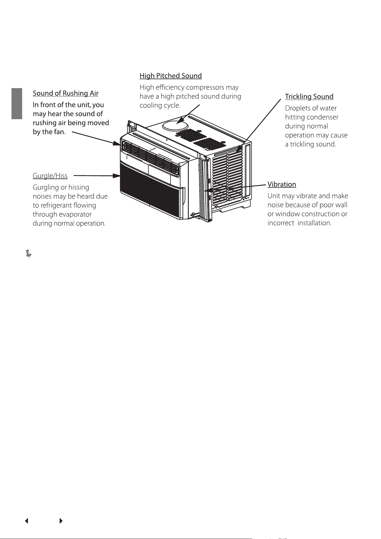
Normal
Sounds
Normal Sounds
NOTE:
All the illustrations in this manual are for explanation purpose only. The air condi-
tioner you have may be slightly different. The actual shape shall prevail.
Page 25
Air Conditioner
Features
Air Conditioner Features
WARNING
To reduce the risk of fire, electric shock, or injury to persons, read the IMPORTANT
SAFETY INSTRUCTIONS before operating this appliance.
CAUTION
Please always wait 3 minutes when turning unit off then on again, and when chang-
ing from cool to fan and back to cool. This prevents compressor from overheating
& possible circuit breaker tripping.
To begin operating the air conditioner, follow these steps:
(1) Set the thermostat to the highest number (coldest or cooler setting).
(2) Set the selector control to the highest COOL setting.
(3) Adjust the louver for comfortable air flow (see Air Directional Louvers).
(4) Once the room has cooled, adjust the thermostat to the setting you find most
comfortable.
(5) Make sure that the air flow inside and outside are not obstructed by anything.
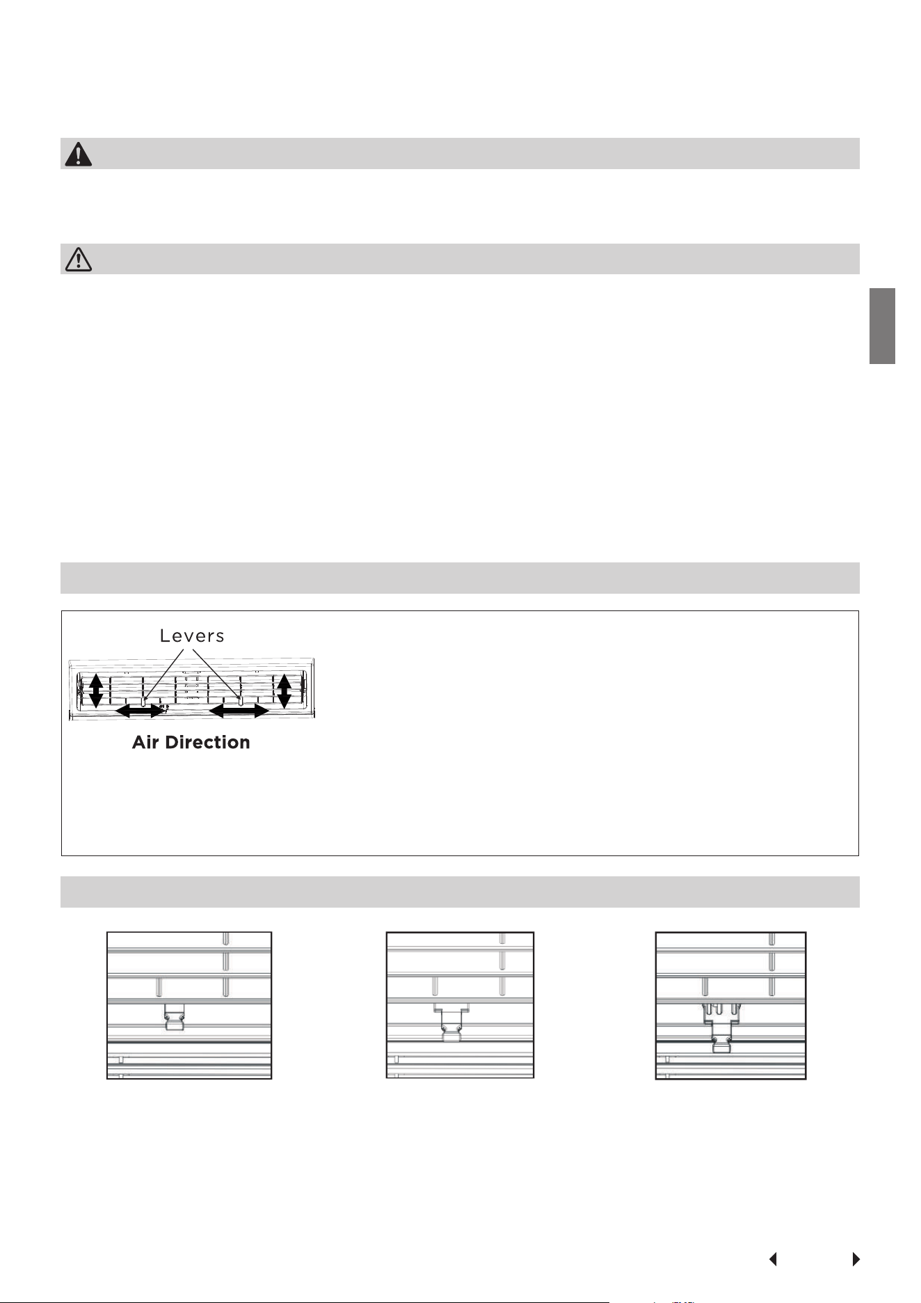
Air Directional Louvers
The louvers will allow you to direct the air flow Up or Down(on some models) and
Left or Right throughout the room as needed. Pivot horizontal louvers until the
desired Up/Down direction is obtained. Move the Lever (s) from side to side until
the desired Left/Right direction is obtained.
Fresh Air Vent Control
Fig. A (VENT CLOSED)
Fig. B (VE
NT OPEN)
Fig. C (VE
NT & EXHAUST OPEN)
The Fresh Air Vent allows the air conditioner to:
(1) Recirculate inside air - Vent Closed (See Fig.A)
(2) Draw fresh air into the room- Vent Open (see Fig.B)
(3) Exchange air from the room and draws fresh air into the room -Vent and
Exhaust Open (see Fig.C)
Page 26
Air Conditioner
Features
Remote Controller Specifications
Model RG51G5(1)/CEU1
Rated Voltage 3.0V( Dry batteries R03/LR03×2)
Signal Receiving Range 8m
Environment 23°F~140°F (-5°C~60°C)
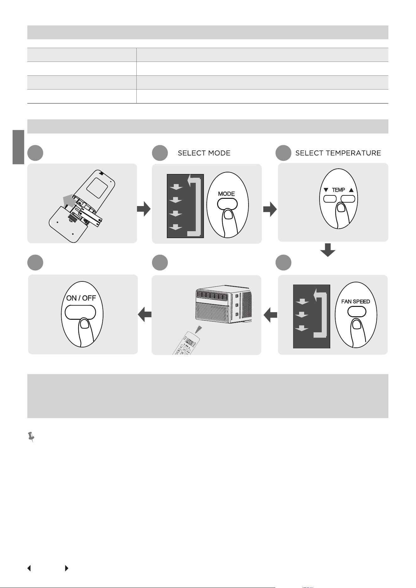
Quick Start Guide
FIT BATTERIES
POINT REMOTE TOWARD
UNIT
PRESS POWER BUTTON
SELECT FAN SPEED
1 2 3
6 5 4
AUTO
LOW
MED
HIGH
AUTO
COOL
DRY
HEAT
FAN
NOT SURE WHAT A FUNCTION DOES?
Refer to the How to Use Basic Functions and How to Use Advanced Functions
sections of this manual for a detailed description of how to use your air condi-
tioner.
SPECIAL NOTE
• Button designs on your unit may differ slightly from the example shown.
• If the indoor unit does not have a particular function, pressing that function’s
button on the remote control will have no effect.
• When there are wide differentces between “Remote controller Manual” and
“USER’S MANUAL” on function description, the description of “USER’S MANU-
AL” shall prevail.
Page 27
Air Conditioner
Features
Handling the Remote Controller
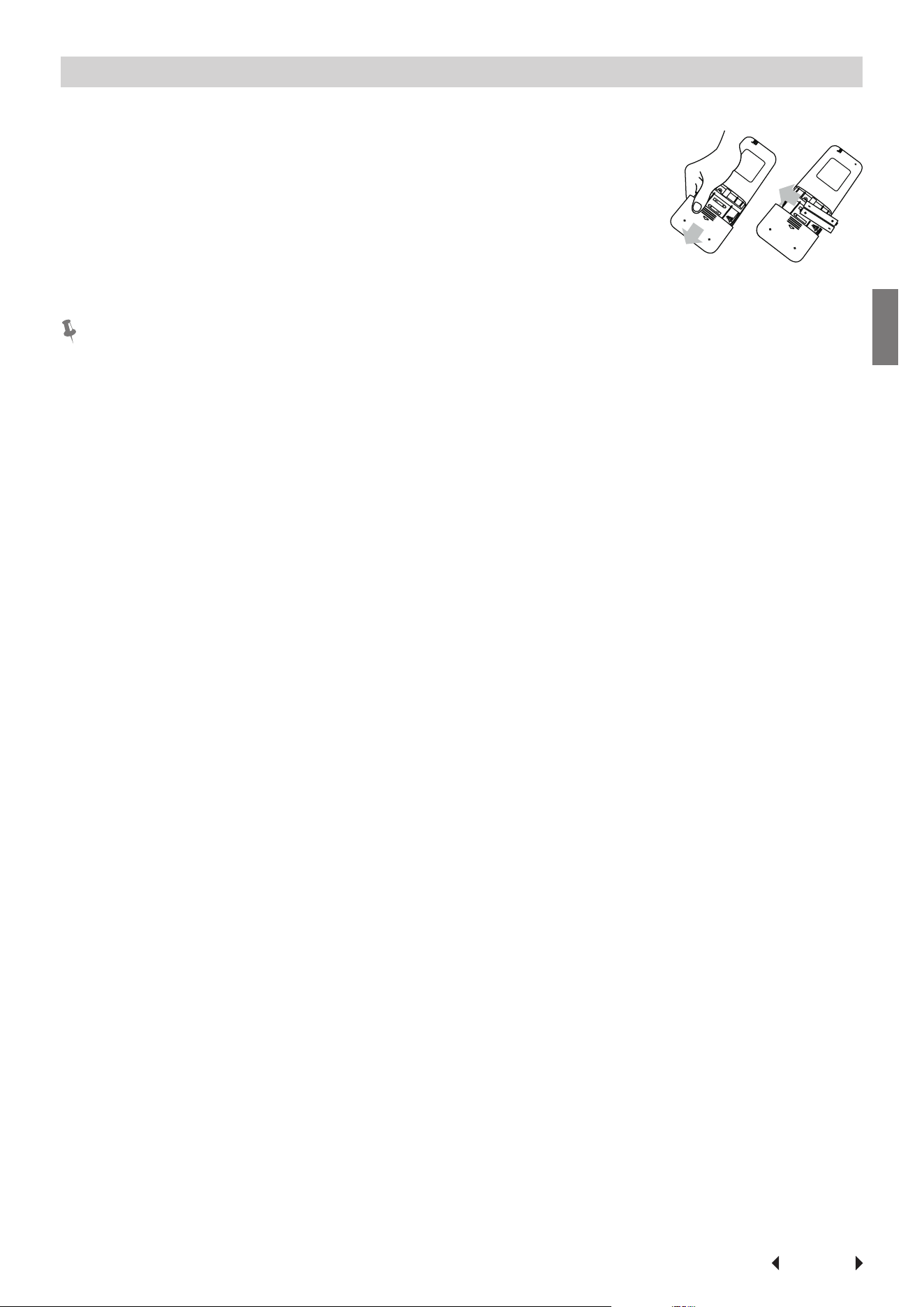
Inserting and Replacing Batteries
Your air conditioning unit may come with two batteries(some
units). Put the batteries in the remote control before use.
1. Slide the back cover from the remote control downward,
exposing the battery compartment
2. Insert the batteries, paying attention to match up the (+)
and (-) ends of the batteries with the symbols inside the
battery compartment.
3. Slide the battery cover back into place.
BATTERY NOTES
For optimum product performance:
• Do not mix old and new batteries, or batteries of different types.
• Do not leave batteries in the remote control if you don’t plan on using the de-
vice for more than 2 months.
BATTERY DISPOSAL
Do not dispose of batteries as unsorted municipal waste. Refer to local laws for
proper disposal of batteries.
TIPS FOR USING REMOTE CONTROL
• The remote control must be used within 8 meters of the unit.
• The unit will beep when remote signal is received.
• Curtains, other materials and direct sunlight can interfere with the infrared sig-
nal receiver.
• Remove batteries if the remote will not be used more than 2 months
NOTES FOR USING REMOTE CONTROL
The device could comply with the local national regulations.
• In Canada, it should comply with CAN ICES-3(B)/NMB-3(B).
• In USA, this device complies with part 15 of the FCC Rules. Operation is subject
to the following two conditions:
(1) This device may not cause harmful interference, and
(2) This device must accept any interference received, including interference
that may cause undesired operation.
This equipment has been tested and found to comply with the limits for a Class B
digital device, pursuant to part 15 of the FCC Rules. These limits are designed to
provide reasonable protection against harmful interference in a residential installa-
tion. This equipment generates, uses and can radiate radio frequency energy and,
if not installed and used in accordance with the instructions, may cause harmful
interference to radio communications. However, there is no guarantee that interfer-
ence will not occur in a particular installation. If this equipment does cause harmful
interference to radio or television reception, which can be determined by turning
the equipment off and on, the user is encouraged to try to correct the interference
by one or more of the following measures:
• Reorient or relocate the receiving antenna. Increase the separation between the
equipment and receiver.
• Connect the equipment into an outlet on a circuit different from that to which
the receiver is connected.
• Consult the dealer or an experienced radio/TV technician for help.
• Changes or modifications not approved by the party responsible for compli-
ance could void user’s authority to operate the equipment.
Page 28
Air Conditioner
Features
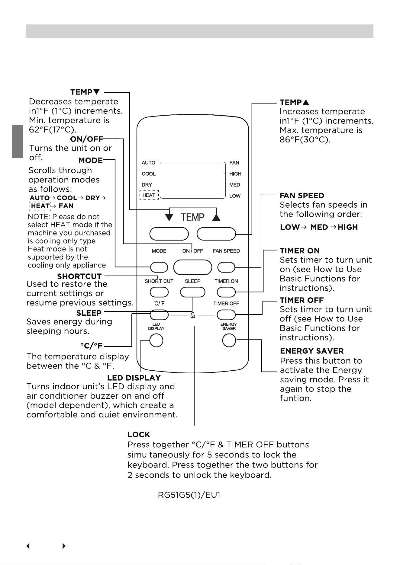
Buttons and Funcitons
Before you begin using your new air conditioner, make sure to familiarize yourself
with its remote control. The following is a brief introduction to the remote control
itself. For instructions on how to operate your air conditioner, refer to the How to
Use Basic Functions section of this manual.
Page 29
Air Conditioner
Features
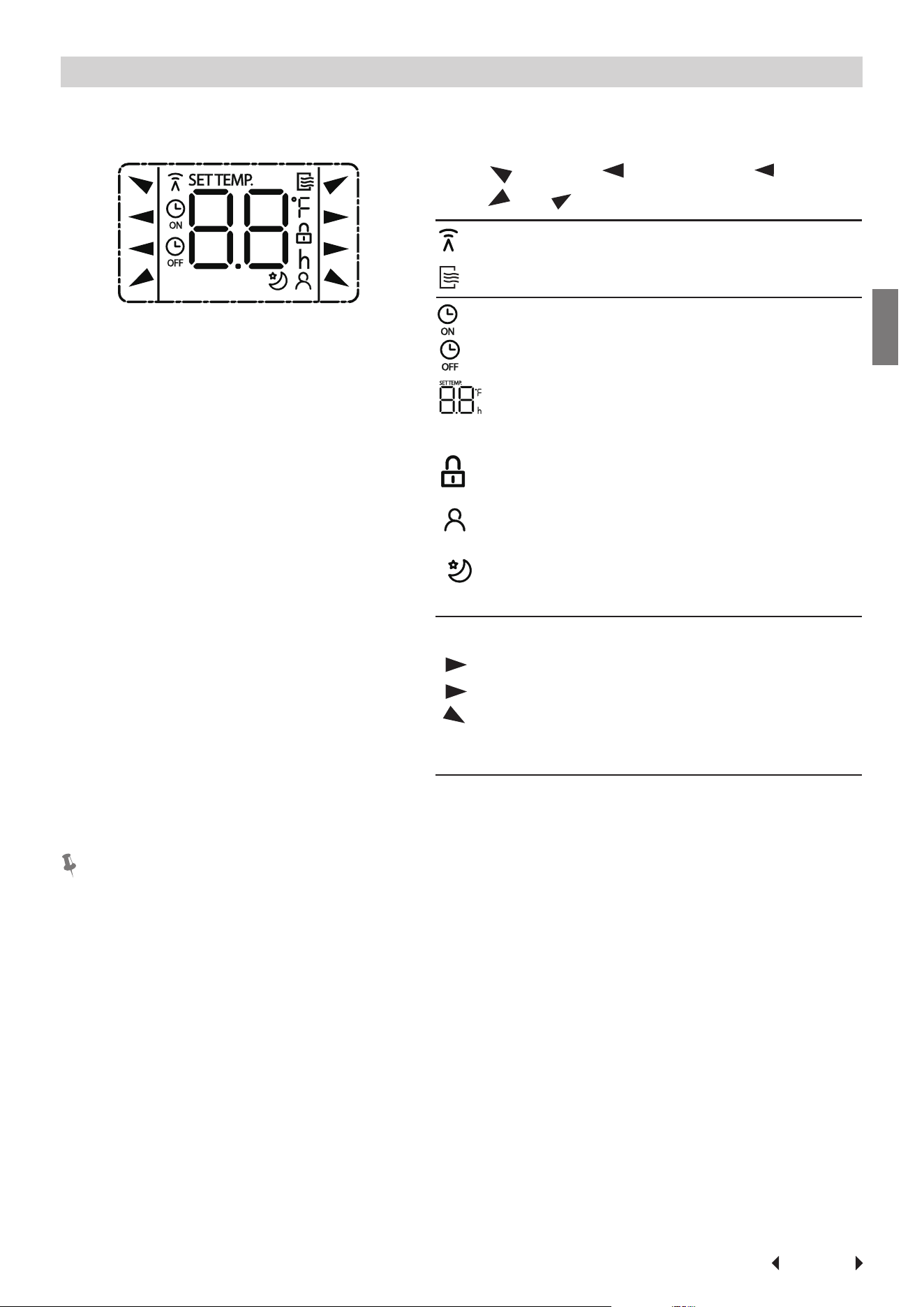
Remote Screen Indicators
Information are displayed when the remote controller is power up.
Displayed when data transmitted.
Displayed when remote controller is ON.
Low speed
NO display
Medium speed
High speed
Auto fan speed
Displayed when TIMER ON time is set
Displayed when TIMER OFF time is set
Indicated all the current settings are
locked
Shows set temperature or room
temperature, or time under TIMER
setting
HIGH
MED
LOW
AUTO
COOL
DRY
HEAT
AUTO
HEAT
COOL
FAN
DRY
Mode display
Fan speed indication
FAN
HIGH
MED
LOW
Displayed when Follow Me feature is
activated(some units)
Displayed when SLEEP feature is
activated
Note:
All indicators shown in the figure are for the purpose of clear presentation. But
during the actaul operation, only the relative function signs are shown on the
display window.
Page 30
Air Conditioner
Features
How to Use Basic Functions
Basic operation
ATTENTION
Before operation, please ensure the unit is plugged in and power is
available.
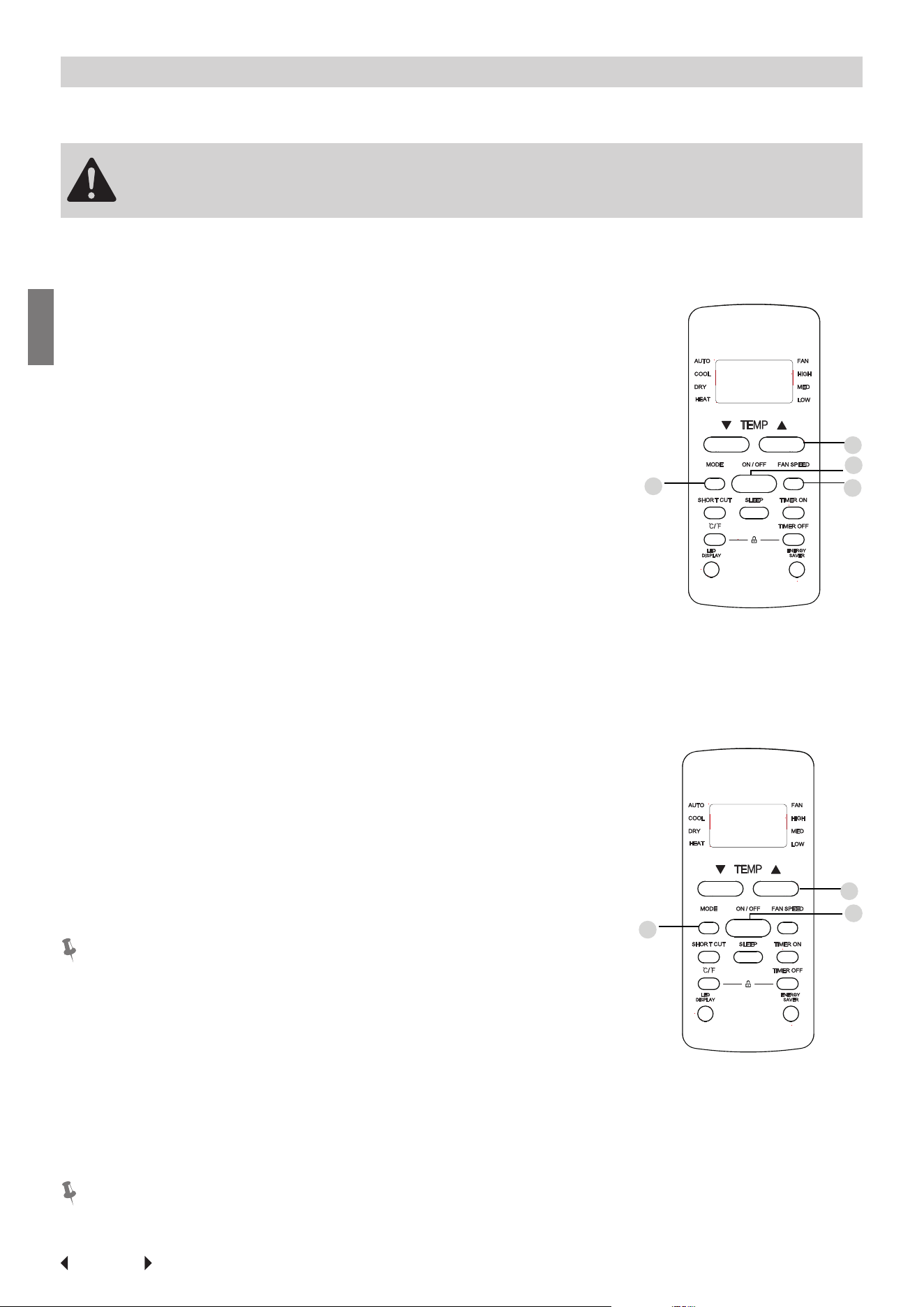
COOL Mode
1. Press the MODE button to select COOL mode.
2. Set your desired temperature using the TEMP or
TEMP button.
3. Press FAN button to select the fan speed: AUTO, LOW,
MED or HIGH.
4. Press the ON/OFF button to start the unit.
SETTING TEMPERATURE
The operating temperature range for units is 62-86°F
(17-30°C ). You can increase or decrease the set tempera-
ture 1 °F(1°C) increments.
AUTO Mode
In AUTO mode, the unit will automatically select the
COOL, FAN, or HEAT operation based on the set temper-
ature.
1. Press the MODE button to select AUTO.
2. Set your desired temperature using the TEMP or
TEMP button.
3. Press the ON/OFF button to start the unit.
NOTE:
FAN SPEED can’t be set in AUTO mode.
In AUTO mode, the unit will automatically select the
COOL, FAN, HEAT or DRY function based on the set tem-
perature.
1. Press the MODE button to select AUTO.
2. Set your desired temperature using the TEMP or TEMP button.
3. Press the ON/OFF button to start the unit.
NOTE:
FAN SPEED can’t be set in AUTO mode.
3
2
4
1
1
3
2
Page 31
Air Conditioner
Features
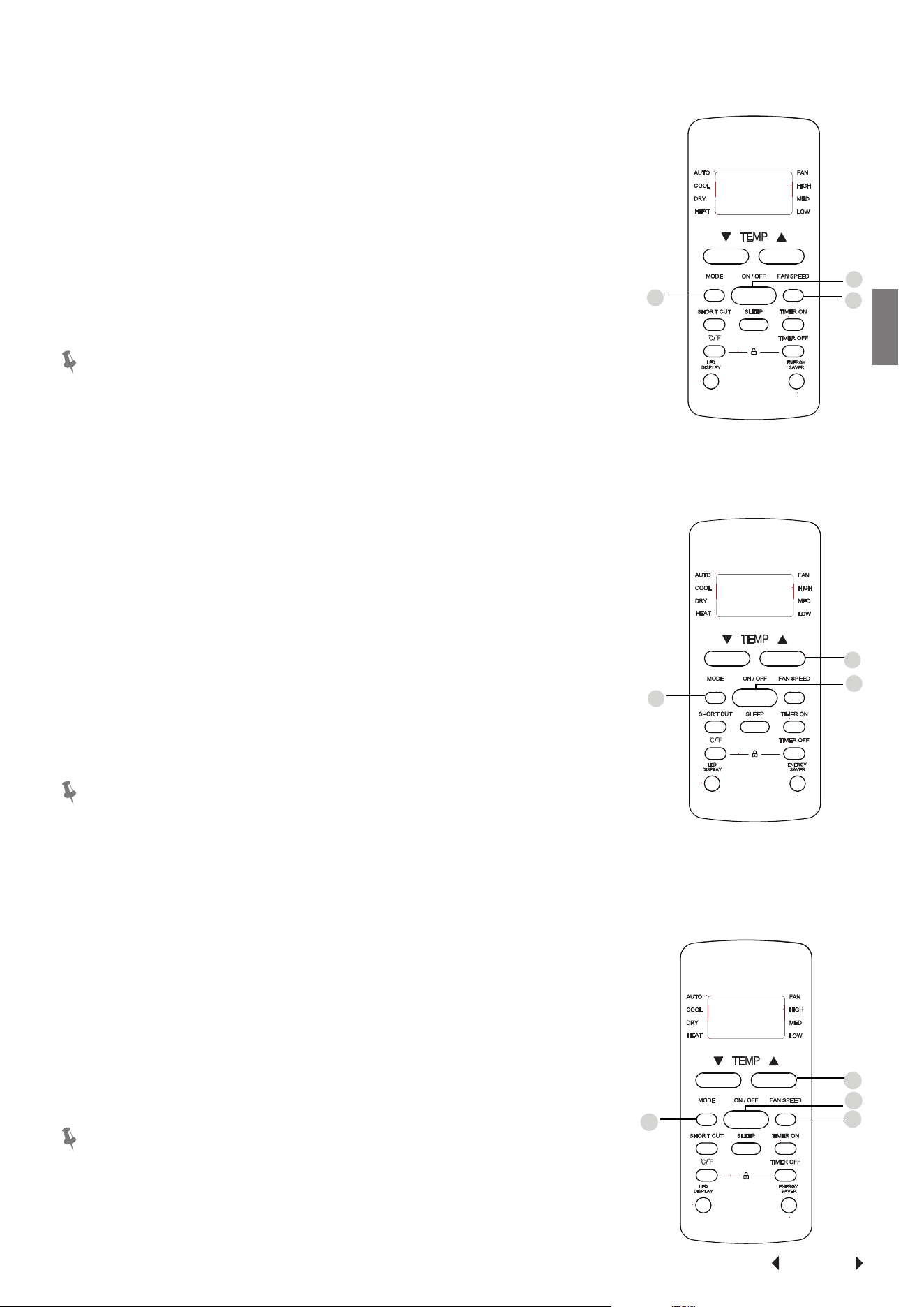
FAN Mode
1. Press the MODE button to select FAN mode.
2. Press FAN button to select the fan speed: AUTO, LOW,
MED or HIGH.
3. Press the ON/OFF button to start the unit.
NOTE:
You can’t set temperature in FAN mode. As a result, your
remote control’s LCD screen will not display temperature.
DRY Mode (dehumidifying)
1. Press the MODE button to select DRY.
2. Set your desired temperature using the TEMP or
TEMP button.
3. Press the ON/OFF button to start the unit.
NOTE:
FAN SPEED cannot be changed in DRY mode.
HEAT Mode (some models)
1. Press the MODE button to select HEAT mode.
2. Set your desired temperature using the TEMP or
TEMP button.
3. Press FAN button to select the fan speed: AUTO, LOW,
MED or HIGH.
4. Press the ON/OFF button to start the unit.
NOTE:
As outdoor temperature drops, the performance of your
unit’s HEAT function may be affected. In such instances,
we recommend using this air conditioner in conjunction
with other heating appliances.
1
3
2
1
3
2
1
3
2
4
Page 32
Air Conditioner
Features
Setting the TIMER
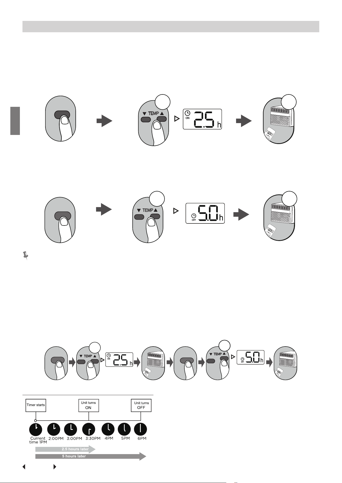
TIMER ON/OFF
Set the amount of time after which the unit will automatically turn on/off.
TIMER ON setting
Press TIMER ON button to
initiate the ON time sequence
Press Temp. up or down button
for multiple times to set the de-
sired time to turn on the unit.
Point remote to unit and wait
1sec, the TIMER ON will be
activated.
TIMER ON
x5
1sec
TIMER OFF setting
Press TIMER OFF button to
initiate the OFF time sequence
Press Temp. up or down button
for multiple times to set the de-
sired time to turn off the unit.
Point remote to unit and wait
1sec, the TIMER OFF will be acti-
vated.
TIMER OFF
1sec
x10
NOTE:
1. When setting the TIMER ON or TIMER OFF, the time will increase by 30 min-
utes increments with each press, up to 10 hours. After 10 hours and up to 24, it
will increase in 1 hour increments. (For example, press 5 times to get 2.5h, and
press 10 times to get 5h,) The timer will revert to 0.0 after 24.
2. Cancel either function by setting its timer to 0.0h.
TIMER ON & OFF setting(example)
Keep in mind that the time periods you set for both functions refer to hours after
the current time.
TIMER ON
TIMER OFF
xn
xnxn
Example: If current timer is 1:00PM, to
set the timer as above steps, the unit will
turn on 2.5h later (3:30PM) and turn off at
6:00PM.
Page 33
Air Conditioner
Features
How to Use Advanced Functions
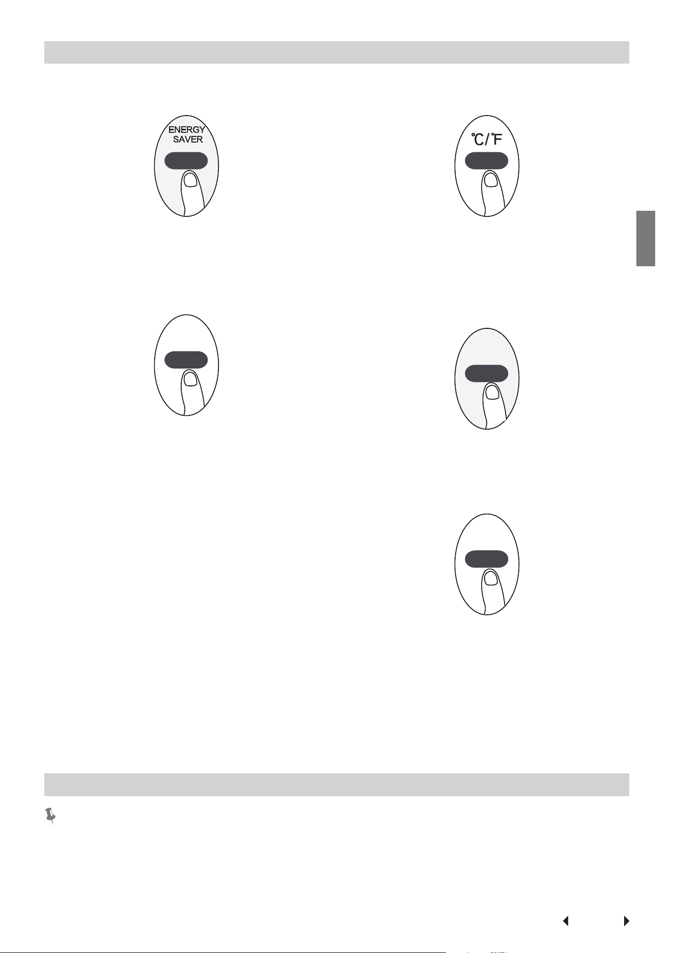
ENERGY SAVER function (some models)
Press Energy saver button to initiate this function.
This function is available on COOL, DRY, AUTO
(only AUTO-COOLING and AUTO-FAN) modes.
SHORTCUT function(some models)
SHORT CUT
Used to restore the current settings or resume
previous settings.(For some models).
Push this button when remote controller is on, the
system will automatically revert back to the pre-
vious settings including operating mode, setting
temperature, fan speed level and sleep feature (if
activated). If pushing more than 2 seconds, the
system will automatically restore the current
operation settings including operating mode, set-
ting temperature, fan speed level and sleep fea-
ture (if activated ).
°C/°F (some models)
Press this button will alternate the temperature
display between the °C & °F.
LED DISPLAY
Press LED button
LED DISPLAY
Press this button to turn on and turn off the dis-
play on the indoor unit.
SLEEP function
SLEEP
The SLEEP function is used to decrease energy
use while you sleep (and don t need the same
temperature settings to stay comfortable). This
function can only be activated via remote control.
The sleep function is not available in Fan or Dry
mode.Please refer to the OWNER’S MANUAL for
more details.
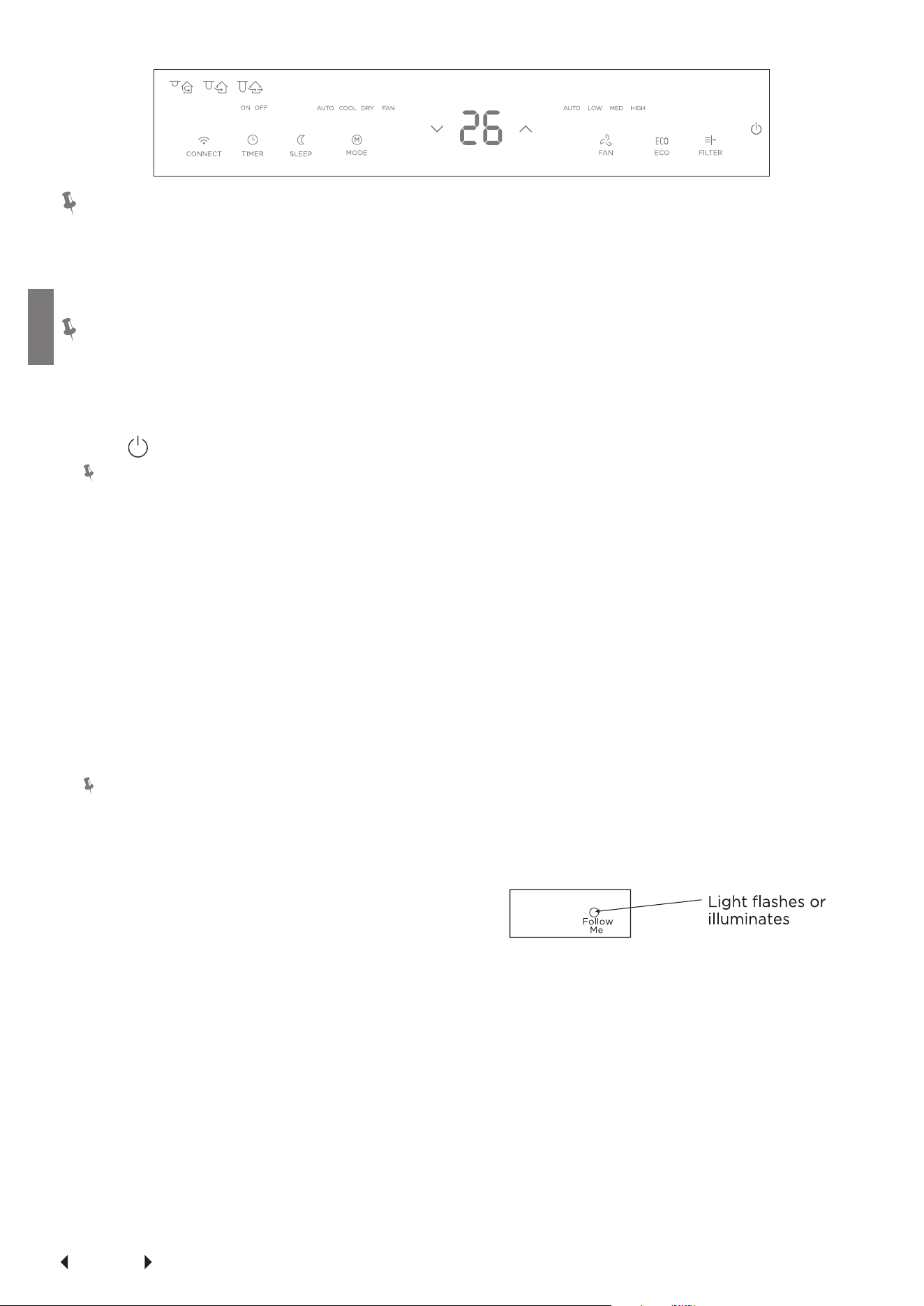
ELECTRONIC CONTROL OPERATING INSTRUCTIONS
NOTE:
Different models have different control buttons and indicator lights. Not all the
control buttons and indicator lights describing below are available for the unit you
purchased. Please check the control panel of the unit you purchased. The unit can
be controlled by the unit control alone or with the remote.
Page 34
Air Conditioner
Features
NOTE:
Ion or clear air may be instead of SMART or WIRELESS or CONNECT for some
models. Heat, clean air, ion, smart, Wireless, Connect and follow me features are
optional.Ion, clean air is not applicable for R32/R290 units. Ion, clean air, smart,
wireless and connect features may be not applicable for some models.
NOTE:
The outline of the operation panel is based on typical model, the function is thesa-
me with your air conditioner while some difference may exist in appearance.
1. TO TURN UNIT ON OR OFF:
Press
POWER button to turn unit on or off.
NOTE:
The unit will initiate automatically the Ener-
gy Saver function under Cool, Dry and Auto
modes.
2. CLEAN AIR(ION)/SMART(WIRELESS or CON-
NECT)FEATURE: (on some models)
Press Clean Air(ION) button,the ion generator
is energized and will help to remove pollen
and impurities from the air, and trap them in
the filter. Press SMART(WIRELESS or connect)
button for 3 seconds to turn off the unit and
initiate SMART (WIRELESS or connect)connec-
tion mode.
3. TO CHANGE TEMPERATURE SETTING:
Press UP/DOWN buttonto changetemperature
setting.
NOTE:
Press or hold either UP or DOWN button until
the desired temperature is shown on the dis-
play. This temperature will be automatically
maint-ained anywhere between 62°F (17°C)
and 86°F (30°C). If you want the display to
read the actual room temperature, see“ To Op-
erate on Fan Only ’’ section.
4. SLEEP FEATURE
Press Sleep button to initiate the sleep mode.
In this mode the selected temperature will in-
crease (cooling) or decrease (heating) by 2°F/1
(or 2)°C 30 minutes after the mode is selected.
The temperature will then increase (cooling) or
decrease (heating) by another 2°F/1 (or 2)°C
after an additional 30 minutes. This new tem-
perature will be maintained for 6 or 7 hours
before it returns to theoriginally selected
temperature. This ends the Sleep mode and
the unit will continue to operate as originally
programmed. The Sleep mode program can
be cancelled at any time during operation by
pressing the Sleep button again.
5. TO ADJUST FAN SPEEDS:
Press Fan button to select the Fan Speed in
four steps-Auto, Low, Med or High. Each time
the button is pressed, the fan speed mode is
shifted. For some models, the fan speed can
not be adjusted.
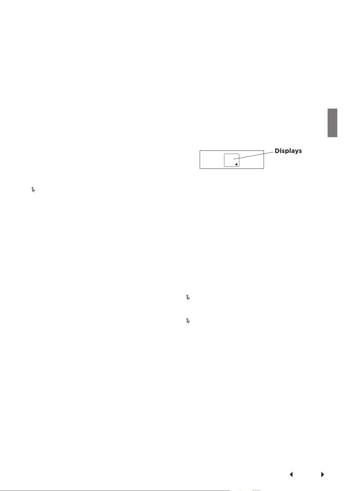
6. CHECK FILTER FEATURE:
Press Check filter button to initiate theis fea-
ture. This feature is a reminder to clean the Air
Filter for more efficient operation. The LED
(light) will illuminate after 250 hours of opera-
tion. To reset after cleaning the filter, press the
Check Filter button and the light will go off.
7. ENERGY SAVER FEATURE:
Press Energy saver button to initiate this func-
tion. This function is available on COOL, DRY,
AUTO (only AUTO-COOLING and AUTO-FAN)
modes. The fan will continue to run for 3 min-
utes after the compressor shuts off.The fan then
cycles on for 2 minutes at 10 minute intervals
until the room temperature is above the set
temperature, at which time the compressor
turns back on and Cooling Starts.
8. FOLLOW ME FEATURE:(on some models)
This feature can be activated from the remote
control ONLY. The remote control serves as
a remote thermostat allowing for the precise
temperature control at its location.
To activate the Follow Me feature, point the
remote control towards the unit and press the
Follow Me button. The remote display is actual
temperature at its location. The remote con-
trol will send this signal to the air conditioner
every 3 minutes interval until press the Follow
Me button again.If the unit does not receive the
Follow Me signal during any 7 minutes interval,
the unit will beep to indicate the Follow Me
mode has ended.
Page 35
Air Conditioner
Features
9. TO SELECT THE OPERATING MODE:
To choose operating mode, press Mode button.
Each time you press the button, a mode is se-
lected in a sequence that goes from Auto, Cool,
Dry ,heat (cooling only models without)and
Fan. The indicator light beside will be illuminat-
ed and remained on once the mode is selected.
The unit will initiate automatically the Energy
Saver function under Cool, Dry, Auto (only Au-
to-Cooling and Auto-Fan) modes.
To operate on COOL mode:
• Choose Cool Mode to set the cooling func-
tion. Use the Up and Down buttons to
choose the desired temperature. When Cool
Mode is selected, the fan speed can be ad-
justed by pressing the fan button.
To operate on HEAT mode (cooling only
models without):
• Choose Heat Mode to set the heating func-
tion. Use the Up and Down buttons to
choose the desired temperature .When heat
Mode is selected, the fan speed can be ad-
justed by pressing the fan button.
NOTE:
For some models, the fan speed can not be
adjusted under HEAT mode.
To operate on Auto feature:
• When you set the air conditioner in AUTO
mode, it will automatically select cooling,
heating (cooling only models without), or
fan only operation depending on what tem-
perature you have selected and the room
temperature.
• The air conditioner will control room temper-
ature automatically round the temperature
point set by you.
• In this mode, the fan speed cannot be ad-
justed, it starts automatically at a speed
according to the room temperature.
To operate on Fan Only:
• Use this function only when cooling is not
desired,such as for room air circulation
or to exhaust stale air (on some models).
(Remember to open the vent during this
function, but keep it closed during cooling
for maximum cooling efficiency.) You can
choose any fan speed you prefer.
• During this function, the display will show
the actual room temperature, not the set
temperature as in the cooling mode.
• In Fan only mode ,the temperature is not
adjusted.
To operate on Dry mode:
• In this mode, the air conditioner will gener-
ally operate in the form of a dehumidifier.
Since the conditioned space is a closed or
sealed area, some degree of cooling will
continue. On Dry mode,the fan speed is con-
trolled at Low automatically.
10. TIMER:AUTO START/STOP FEATURE:
• Press Timer button, the TIMER ON or TIMER
OFF indicator light illuminates. It indicates
the Auto Start or Auto Stop program is initi-
ated. For some units, keep pressing the Tim-
er button will cancel the timer settings.
• Press or hold the UP or DOWN button to
change the Auto time by 0.5 hour incre-
ments, up to 10 hours,then at 1 hour incre-
ments up to 24 hours. The control will count
down the time remaining until start.
• The selected time will register in 5 seconds,
and the system will automatically revert
back to display the previous temperature
setting or room temperature when the unit is
on.(when the unit is off,there is no display.)
• Turning the unit ON or OFF at any time or
adjusting the timer setting to 0.0 will cancel
the Auto Start/Stop timed program.
11. DISPLAYS:
Shows the set temperature in "°C" or "°F"
and the Auto-timer settings.While on Fan only
mode, it shows the room temperature. If the
room temperature is too high or low, it will dis-
play "HI" or "LO".
Error codes:
AS - Room temperature sensor error
ES -Evaporator temperature sensor error
NOTE: " • " is displayed as shown in the obove
picture.
HS -Electric heating sensor error(on some
models);
CS -Condenser temperature sensor error (on
some models);
OS -Outside temperature sensor error (on some
models);
E7 -Unit malfunction (on some models).
NOTE:
When error occurs, unplug the unit and plug it
back in.If error repeats, call for service.
NOTE:
If the unit breaks off unexpectedly due to the
power cut, it will restart with the previous
function setting automatically when the power
resumes.
12. ADDITIONAL THINGS YOU SHOULD KNOW
Now that you have mastered the operating pro-
cedure, here are more features in your control
that you should become familiar with.
• The Cool circuit has an automatic 3 minutes
time delayed start if the unit is turned off
and on quickly. This prevents overheating of
the compressor and possible circuit breaker
tripping.The fan will continue to run during
this time.
• The control is capable of displaying temper-
ature in degrees Fahrenheit or degrees Cel-
sius. To convert from one to the other, press
and hold the Up and Down buttons at the
same time for 3 seconds.
Page 36
Care and
Cleaning
Care and Cleaning
CAUTION
Clean your air conditioner occasionally to keep it looking new. Be sure to unplug
the unit before cleaning to prevent shock or fire hazards.
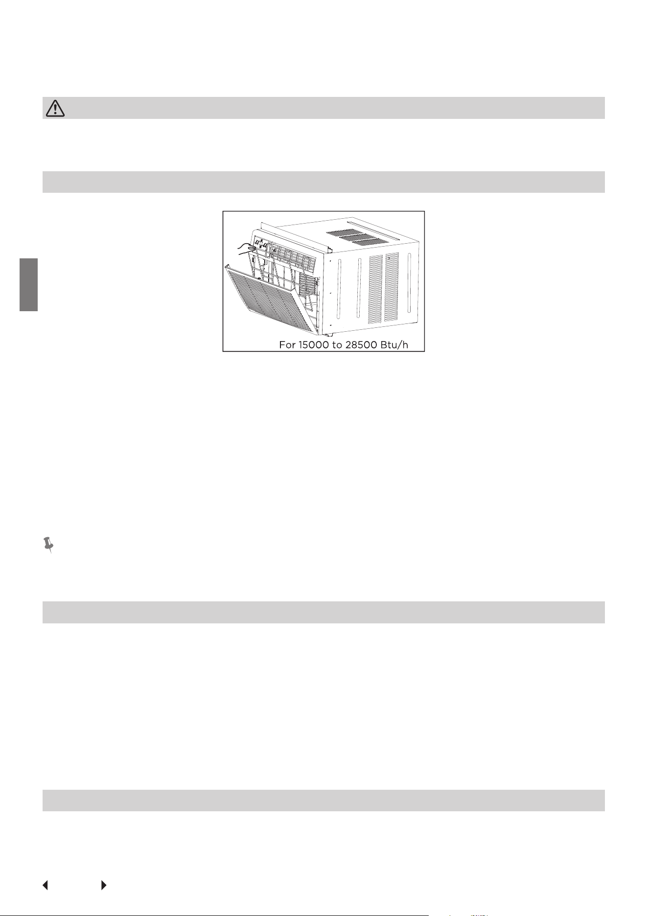
Air Filter Cleaning
The air filter should be checked at least once a month to see if cleaning is neces-
sary. Trapped particles in the filter can build up and cause an accumulation of frost
on the cooling coils.
• Push the vent handle to the Vent Closed position (where applicable). Open the
front panel.
• Take the filter by the center and pull up and out.
• Wash the filter using liquid dishwashing detergent and warm water. Rinse fil-
ter thoroughly. Gently shake excess water from the filter. Be sure the filter is
thoroughly dry before replacing. Instead of washing, you may vacuum the filter
clean.
Note:
Never use hot water over 40°C (104°F) to clean the air filter. Never attempt to op-
erate the unit without the air filter.
Cabinet Cleaning
• Be sure to unplug the air conditioner to prevent shock or fire hazard. The cab-
inet and front may be dusted with an oil-free cloth or washed with a cloth
dampened in a solution of warm water and mild liquid dishwashing detergent.
Rinse thoroughly and wipe dry.
• Never use harsh cleaners, wax or polish on the cabinet front.
• Be sure to wring excess water from the cloth before wiping around the con-
trols. Excess water in or around the controls may cause damage to the air con-
ditioner.
• Plug in air conditioner.
Winter Storage
If you plan to store the air conditioner during the winter, remove it carefully from
the window according to the installation instructions. Cover it with plastic or return
it to the original carton.
Page 37
Troubleshooting
Tips
Troubleshooting Tips
Before calling for service, review this list. It may save your time and expense. This
list includes common occurrences that are not the result of defective
workman-ship or materials in this appliance.
Problem Solution
Air conditioner does not start.
Wall plug disconnected. Push plug firmly into wall outlet.
House fuse blown or circuit breaker tripped. Replace fuse with time
delay type or reset circuit breaker.
Plug Current Device Tripped. Press the RESET button.
Power is OFF. Turn power ON.
Air from unit does not feel
cold enough.
Room temperature below 62°F(17°C). Cooling may not occur until
room temperature rises above 62°F(17°C).
Temperature sensing behind air filter element touching cold coil.
Keep it from the cold coil.
Set to a Lower temperature.
Compressor stopped when changing modes. Wait for 3 minutes
after set to the COOL mode.
Air conditioner cooling, but
room is too warm-ice
forming on cooling coil behind
decorative front.
Outdoor temperature below 64°F(18°C). To defrost the coil, set FAN
ONLY mode.
Air filter may be dirty. Clean filter. Refer to Care and Cleaning sec-
tion. To defrost, set to FAN ONLY mode.
Thermostat set too cold for night-time cooling. To defrost the coil,
set to FAN ONLY mode. Then, set temperature to a Higher setting.
Air conditioner cooling, but
room is too warm-NO ice
forming on cooling coil behind
decorative front.
Dirty air filter- air restricted. Clean air filter. Refer to Care and Clean-
ing section.
Temperature is set too High, set temperature to a Lower setting.
Air directional louvers positioned improperly. Position louvers for
better air distribution.
Front of units is blocked by drapes, blinds, furniture, etc. - restricts
air distribution. Clear blockage in front of unit.
An open doors, windows,or register may allow cold air to escape.
Close any doors, winows, or registers.
The room may be too warm. Allow additional time to remove
“Stored heat” from walls, ceiling, floor and furniture.
Air conditioner turns on and
off rapidly
Dirty air filter- air restricted. Clean air filter.
Outside temperature extremely hot. Set FAN speed to a Higher set-
ting to bring air past cooling coils more frequently.
Noise when unit is cooling
Air movement sound. This is normal . If too loud, set to a slower FAN
setting.
Window vibration - poor installation. Refer to installation instruc-
tions or check with installer.
Page 38
Troubleshooting
Tips
Problem Solution
Water dripping INSIDE when
unit is cooling.
Improper installation. Tilt air conditioner slightly to the outside to
allow water drainage. Refer to installation instructions - check with
installer.
Water dripping OUTSIDE when
unit is cooling.
Unit removing large quantity of moisture from humid room. This is
normal during excessively humid days.
Remote Sensing
Deactivating Prematurely
(Only remote models)
Remote control not located within range. Place remote control with-
in 20 feet and pointed in the general direction of the air conditioner
unit.
Remote control signal obstructed. Remove obstruction.
Room too cold Set temperature too low. Increase set temperatur.
Page 39
Connection
Instructions
Connection Instructions
1. How to Use Matter
Connect Your Air Conditioner Through Matter
Make sure your mobile device is connected to your wireless router.
The wireless router should support and turn on IPv6. Please make sure your
smartphone is connected to the 2.4G, not the 5G network.
For the best Matter compatibility, connect the AC to the Alexa, Google
Home or Apple Home ecosystems, along with at least one of their respec-
tive Matter-enabled smart speakers.
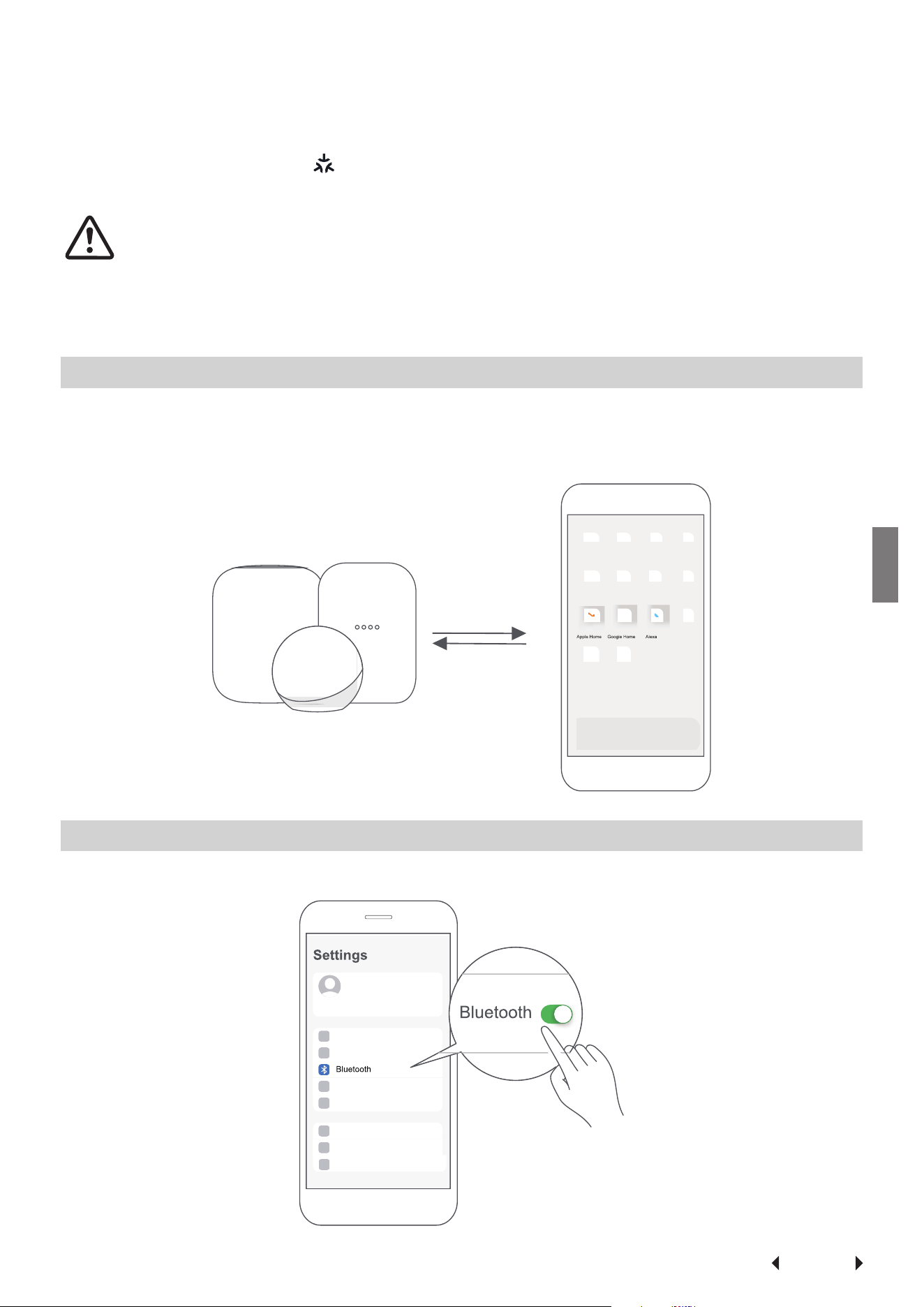
STEP 1: Connect to Smart Speakers
Select your preferred ecosystems (Alexa, Google Home or Apple Home) and make
sure you’ve got one of their Matter-enabled products (such as their smart speak-
ers) connected to your wireless router.
STEP 2: Turn On Bluetooth
Turn on Bluetooth on your mobile device.
Page 40
Connection
Instructions
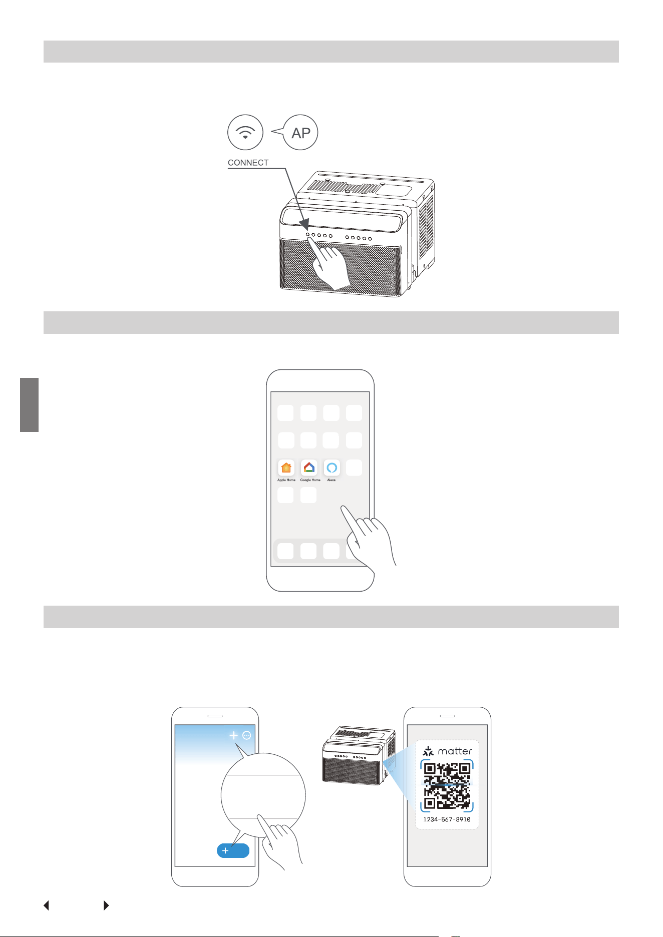
STEP 3: Enter AP Mode
Hold down the CONNECT button for 3 seconds to begin the pairing process (“AP”
will appear on the AC’s display).
STEP 4: Open App
Open the Alexa, Google Home or Apple Home app on your mobile device.
STEP 5: Scan Matter QR code
Tap the “+” and “Add Device/ Accessory” or tap “+Add” in your app, select Matter
device and scan the Matter QR code found on the side of the AC device.
Follow the respective instructions in the Alexa, Google Home or Apple Home app
to complete the pairing process.
Add
Add Device/Accessory
scan
Matter QR code
Page 41
Connection
Instructions
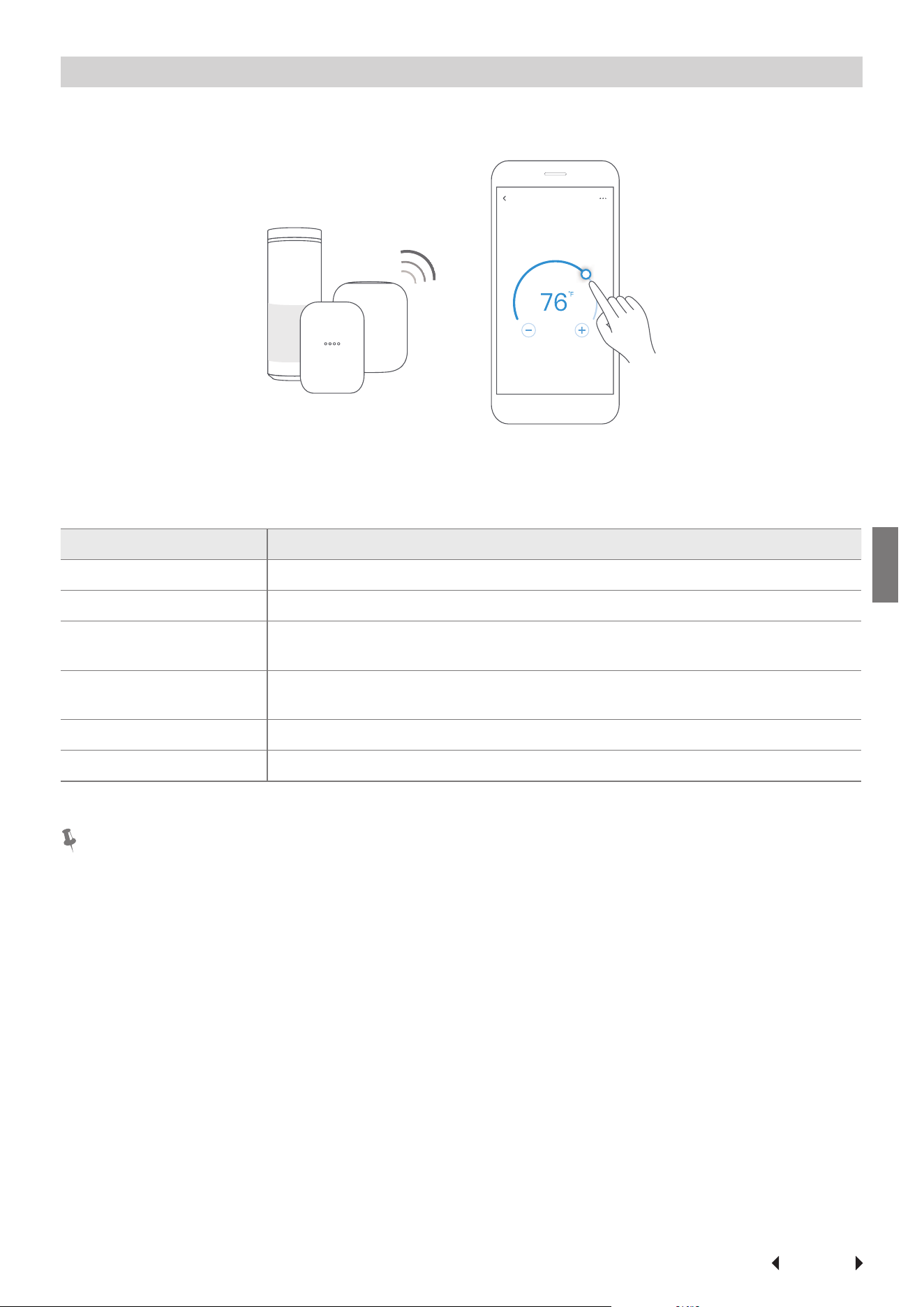
STEP 6: Control Device
After pairing is successful, you can control your AC’s temperature and mode set-
tings, etc. through the respective ecosystem app and/or smart speaker.
Air conditioner
App & Smart Speakers can support Matter only when using these versions or
above.
Device Version
iPhone iOS 16.5
Apple Home Pod 16.5
Android
Google Play services min version: 22.36.15
Google Home app (GHA) min version: 2.58.24.1 - dogfood
Google Home Hub
Google Hub firmware min version: 1.56.324896
(appears on hub as Chromecast firmware version)
Alexa App 2.2.536317
Alexa Echo Device 9094439556
NOTE
• Setup processes and features may vary between ecosystems.
• Make sure the Matter-enabled app is up to date to ensure the best experience.
• Periodically, we will update the device’s software to improve the experience.
Device software updates can be accomplished through the SmartHome app.
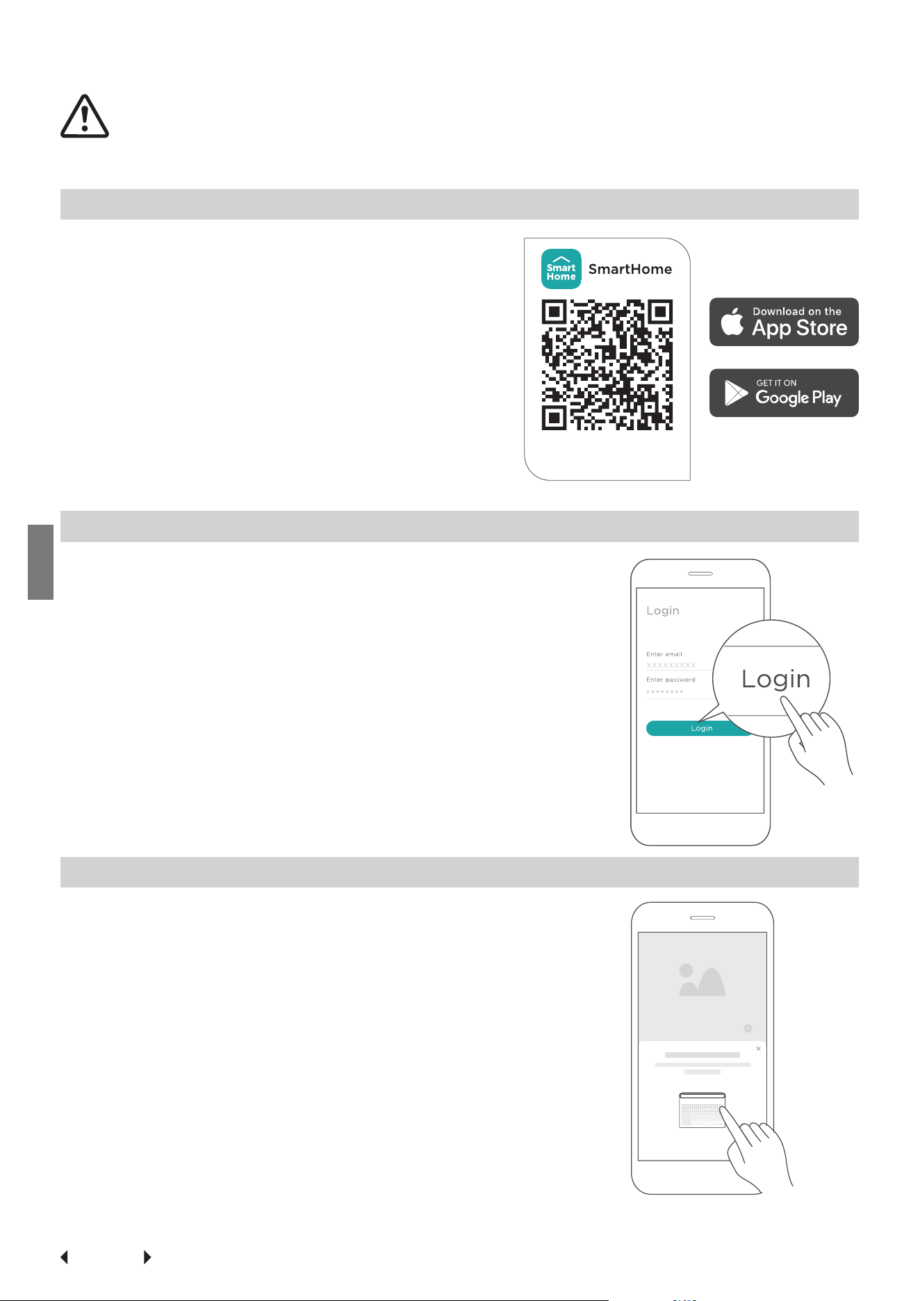
Page 42
Connection
Instructions
2. How to Use SmartHome
Ensure that your mobile phone is connected to the wireless network. Blue-
tooth must be turned on. The device must also be powered on.
STEP 1: Download the SmartHome App
Scan the QR code below to download the
SmartHome app from the app store or search
for it directly on the Google Play Store or Ap-
ple’s App Store.
STEP 2: Log in
Open the SmartHome app. Log in directly if you have an
existing SmartHome account or create a new account.
Alternatively, you can also use a 3rd party login platform.
STEP 3: Connecting the Device
(1) When you log in, you may see the message “Smart
devices discovered nearby”.Tap to add your device.
Download the app
& activate product
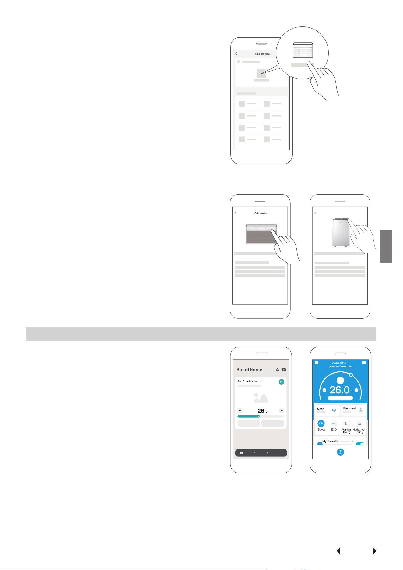
Page 43
Connection
Instructions
(2) If no such message appears, proceed as
follows: Tap on “+” and select your device
in the list of nearby available devices.
If your device is not listed, please add your
device manually. Select the device catego-
ry (e.g. Window AC) and find your device
model in the list.
(3) Follow the steps in the app to connect
your device to the wireless network. If your
device fails to connect, follow the addi-
tional instructions in the app.
STEP 4: Controlling the Device
After pairing successfully, a card will be creat-
ed for the device in the SmartHome app.
Shortcuts for basic functions will appear on
the card, such as changing the temperature or
switching the device on or off.
Tapping on the card will reveal additional fea-
tures and settings. The actual UI design may
look different from examples due to app up-
dates.
For Window AC For Portable AC
Add device

Unit model: MAW18RA1CWT Operation Temperature: 0°C ~ 45°C / 32°F ~ 113°F
Wireless Module Model: US-SK109 Operation Humidity: 10% ~ 85%
Antenna Type: Printed PCB Antenna Power Input: DC 5V/500 mA
Wireless: 2400 - 2483.5MHz, TX Power: < 20dBm BLE: 2402 - 2480MHz, TX Power: < 10dBm
Declaration of Conformity
Specifications
FCC ID: 2ADQOMDNA23
IC: 12575A-MDNA23
This device complies with Part 15 of the FCC Rules and Industry Canada’s licence exempt RSSs.
Operation is subject to the following two conditions:
(1) This device may not cause interference;
(2) This device must accept any interference, including interference that may cause undesired operation of
the device.
Only operate the device in accordance with the instructions supplied.
Changes or modifications to this unit not expressly approved by the party
responsible for compliance could
void the user’s authority to operate the equipment.
This device complies with FCC radiation exposure limits set forth for an uncontrolled environment. In order
to avoid the possibility of exceeding the FCC radio frequency exposure limits, human proximity to the
antenna shall not be less than 20cm (8 inches) during normal operation.
This device is in compliance with the essential requirements and other relevant provisions of Directive 2014/53/EU.
In order to avoid the possibility of exceeding the radio frequency exposure limits, human proximity to the antenna
shall not be less than 20cm during normal operation. (European Union products only)
This equipment has been tested and found to comply with the limits for a Class B digital device, pursuant to part
15 of the FCC Rules. These limits are designed to provide reasonable protection against harmful interference in a
residential installation.
This equipment generates, uses and can radiate radio frequency energy and, if not installed and used in
accordance with the instructions, may cause harmful interference to radio communications. However, there is
no guarantee that interference will not occur in a particular installation. If this equipment does cause harmful
interference to radio or television reception, which can be determined by turning the equipment off and on, the
user is encouraged to try to correct the interference by one or more of the following measures:
• Reorient or relocate the receiving antenna.
• Increase the separation between the equipment and receiver.
• Connect the equipment into an outlet on a circuit different from that to which the receiver is connected.
• Consult the dealer or an experienced radio/TV technician for help.
NOTE
Page 44

Supplier’s Declaration of Conformity
Per FCC Part 2 Section 2.1077
Unique Identifier: Midea brand, RG51G5(1)/CEU1
Responsible Party – U.S. Contact Information
Midea America Corporation
300 Kimball Dr
Parsippany NJ
07054
Telephone number or internet contact information: Midea.com/us
FCC Compliance Statement
This device complies with Part 15 of the FCC Rules. Operation is
subject to the following two conditions: (1) This device may not
cause harmful interference, and (2) this device must accept any
interference received, including interference that may cause un-
desired operation.
Page 46
Warranty
Warranty
Air Conditioner Limited Warranty
Your product is protected by this Limited Warranty:
Warranty service must be obtained from Midea Consumer Services or an author-
ized Midea servicer.
Warranty
• Three Year Full warranty from the date of delivery or the purchase date, which-
ever is later.
• The date of delivery establishes the warranty period, should service be re-
quired.
Midea, through its authorized servicers will:
• Pay all costs for reparing or replacing parts of this appliance which prove to be
defective in materials or workmanship.
Consumer will be responsible for:
• Diagnostics, removal, transportation and reinstallation cost required because of
service.
• Costs of service calls that are a result of items listed under NORMAL RE-
SPONSABILITIES OF THE CONSUMER**
Midea replacement parts shall be used and will be warranted only for the original
warranty.
NORMAL RESPONSABILITIES OF THE CONSUMER**
This warranty applies only to products in ordinary household use, and the con-
sumer is responsible for the items listed below:
1. Proper use of the appliance in acordance with instructions provided with the
product.
2. Routine maintenance and cleaning necessary to keep the good working condi-
tion.
3. Proper installation by an authorized service professional in accordance with in-
structions provided with the appliance and in accordance with all local plumb-
ing, electrical and/or gas codes.
4. Proper connection to a grouded power supply of sufficient voltage, replace-
ment of blown fuses, repair of loosen connections or defects in house wiring.
5. Expenses
for making the appliance accessible for servicing.
6. Damages to finish after installation.
EXCLUSIONS
This warranty does not cover the following:
(1) Failure caused by damage to the unit while in your possesion (other than dam-
age caused by defect or malfunction), by its improper installation, or by un-
reasonable use of the unit, including without limitation, failure to provide rea-
sonable and necessary maintenance or to follow the written installation and
Operating Instructions.
Page 47
Warranty
(2) Damages caused by services performed by persons other than those author-
ized by Midea customer service; or external causes such as abuse, misuse, inad-
equate power supply or acts of God.
(3) If the unit is put to commercial, business, rental, or other use or application oth-
er than for consumer use, we make no warranties, express or implied, including
but not limited to, any implied warranty of merchantability or fitness for use or
purpose.
(4) Products without original serial numbers or products that have serial numbers
which have been altered or cannot be readily determined.
NOTICE: Some states do not allow the exclusions or limitation of incidental or
consequential damages. So this limitation or exclusion may not apply to you.
IF YOU NEED SERVICE
Keep your bill of sale, delivery slip, or some other appropriate payment Record. The
date on the bill establishes the warranty period, should service be required. If ser-
vice is performed, its your best interest to obtain and keep all receipts.
This written warranty gives you specific legal rights. You may also have other rights
that vary from state to state. Service under this warranty must be obtained by fol-
lowing these steps, in order:
(1) Contact Midea Consumer Services or an authorized Midea services at 1 866 646
4332.
(2) If there is a question as to where to obtain service, contact our consumer rela-
tions Departament.


16120300A37153