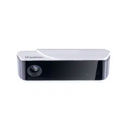
Smar t Cou nter Provide r
— 1 —
User's Manual
3D People Counter
HX-CCD23 ( Bus Property Version)
Smart Counter Provider
Version 2025-1.2

Smar t Cou nter Provide r
— 2 —
Content
1. Product Structure ......................................................................................... 3
1.1 Packing List ......................................................................................... 3
1.2 Product Size ........................................................................................ 4
1.3 Appearance and Function ....................................................................4
2. Installation Instructions ................................................................................ 5
2.1 Installation Notes ................................................................................. 5
2.2 Installation Height and Coverage .........................................................5
2.3 Factors Affecting Accuracy ...................................................................6
3. Installation Steps ..........................................................................................6
3.1 Ceiling Installation ................................................................................6
4. Enter the Device Configuration Page ...........................................................7
4.1 Device Powered on ..............................................................................7
4.2 Connect Devices Using Hotspot .......................................................... 8
4.3 Connect the Device Using a Network Cable ........................................9
5. Device Configuration Page Operations ...................................................... 11
5.1 Go to the Device Homepage and Select the "Settings" Option ..........11
5.2 Set the Height Parameter ...................................................................11
5.3 Set Detection Area and Detection Line .............................................. 12
5.4 Network Settings (Optional) ............................................................... 13
5.5 Data Reporting Settings (Optional) .................................................... 14
5.6 Equipment Upgrade (Optional) .......................................................... 15
5.7 Map Collection (Optional) .................................................................. 15
6. Common Faults and Handling Methods .....................................................16
6.1 Device Cannot be Found in Wired Mode ........................................... 16
6.2 Notes ................................................................................................. 16
Smar t Cou nter Provide r
— 3 —
1. Product Structure
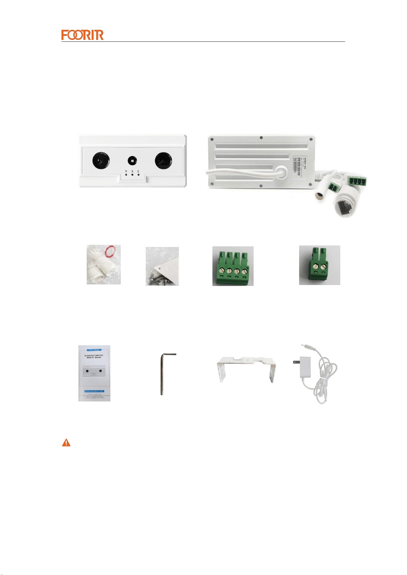
1.1 Packing List
• Product Pictures
Front View Back View
• Accessories
Instructions Inner Hexagon Spanner Bracket Power Adapter
If any of the above items are damaged or lost, please contact your supplier in time.
Waterproof Cap Screw I/O and 485 Connectors Power Connector
Smar t Cou nter Provide r
— 4 —
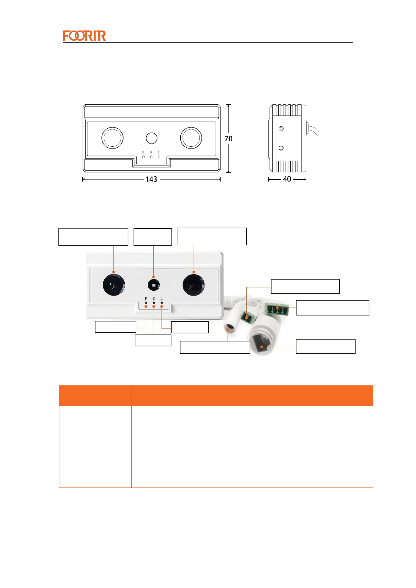
P Light
S Light
L Light
Binocular camera
Fill Light
DC Power Supply
Ethernet port
Power interface
RS485&DI/DO port
Binocular camera
1.2 Product Size
Unit: mm
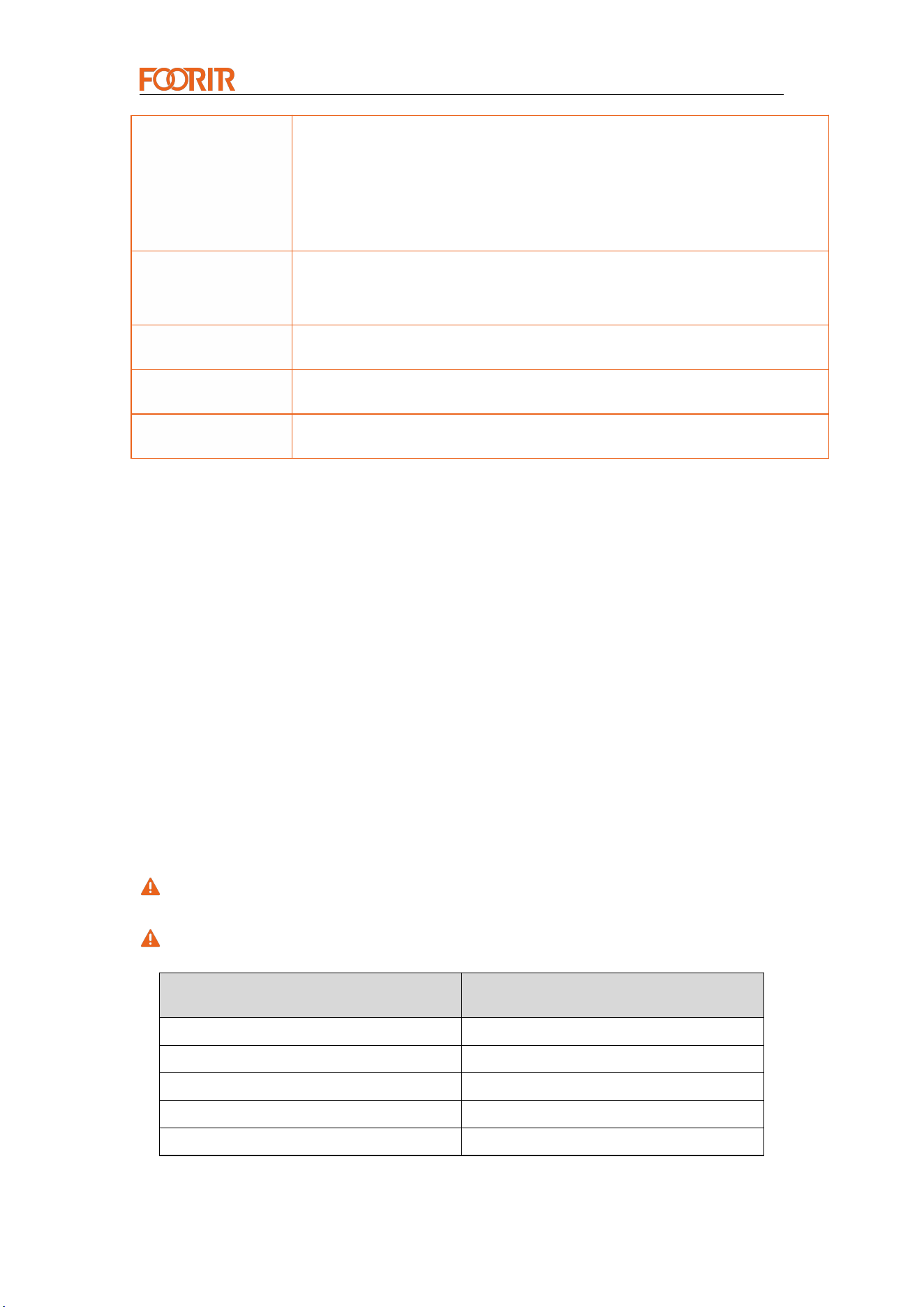
1.3 Appearance and Function
Name
Description
Power indicator
light
P light is always on
Power on
flashing
PSL three lights flash once
Network Status
(Link light)
①
Plug in Ethernet cable: L light is always on
②
During data communication: L light flashes
③ When there is no Ethernet cable or communication, the L light will
turn off
Smar t Cou nter Provide r
— 5 —
System operating
status
① The system is not running properly: The S light is not on (problems
detected with the calibration file, etc.)
② The system is running normally and the connection to the server is
normal: S light is always on
③ The system is running normally but not connected or
communicating with the configured server: S light flashing
RS485&DI/DO Port
Port 1: 485A, Port 2: 485B,
Port 3&4:DI and DO interfaces
Attention: For port 1234, please refer to the numbers on the interface
Ethernet interface
RJ45 interface/PoE port
Power interface
3.5mm-2Pin power interface (9-36V)
DC power supply
5.5-2.1 Power interface (9-36V)
2. Installation Instructions
2.1 Installation Notes
Be careful not to get too close to the wall during installation. It is best to keep a
distance of 50cm.
There should be no wiring harnesses or objects near the device, which will
interfere with device detection.
The device needs to be installed horizontally and does not support tilted
installation.
2.2 Installation Height
It is recommended to find an installation location at a suitable height based on the
coverage area required.
The field of view is the visible range of the screen, not the actual detection range.
Installation Height (m)
Coverage Width (m)
1.7
1.1
2.1
2.2
2.5
4.4
2.7
5.49
3.0
7.0
Smar t Cou nter Provide r
— 6 —
2.3 Factors Affecting Accuracy
No objects should be near the device, which may interfere with the device's
detection.
The detection line should only cover the ground, and should not be drawn on
other higher objects.
If there are other similar sensor devices nearby, there may be interference.
3. Installation Steps
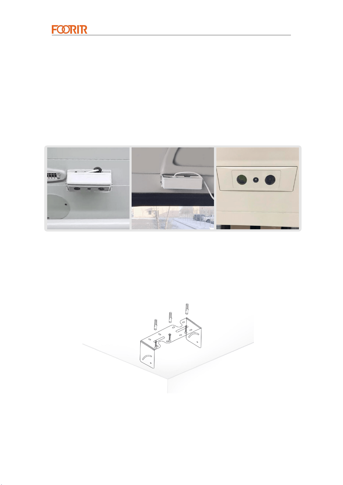
Top-mounted Wall-mounted Embedded
3.1 Ceiling Installation
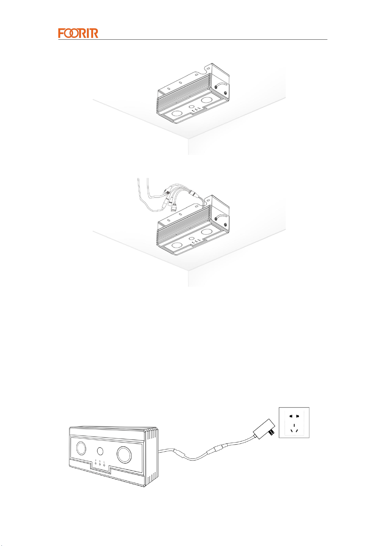
Step 1: Mark the installation position of the bracket with a marker, drill the installation
holes with an electric drill, fix the expansion screw slots in the holes on the ceiling, and
install the bracket firmly with the expansion screws.
Step 2: Embed the device into the bracket, align the holes on the side of the bracket
with the screw holes on the device, and fix it with the standard 304 cylindrical head
hexagon screws.
Smar t Cou nter Provide r
— 7 —
Step 3: Supply power to equipment and the grid.
4. Device Connection and Startup
4.1 Device powered on
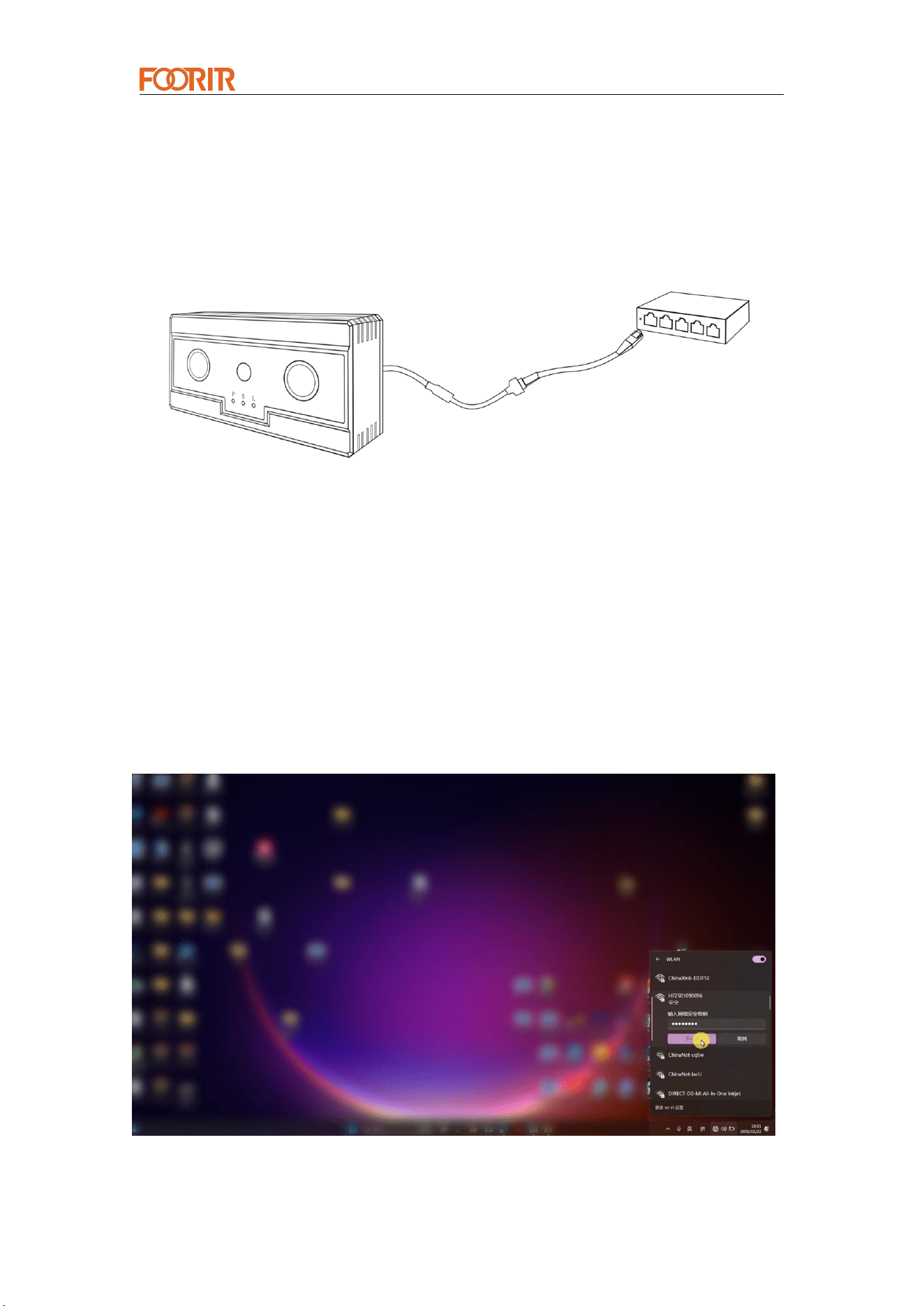
Binocular passenger flow statistics products currently have two power supply
methods:
1. DC:9~36V Power supply
Plug the standard DC 12V power adapter into the 220V power supply and connect
the 12V output harness terminals to the camera's 12V power supply port.
Smar t Cou nter Provide r
— 8 —
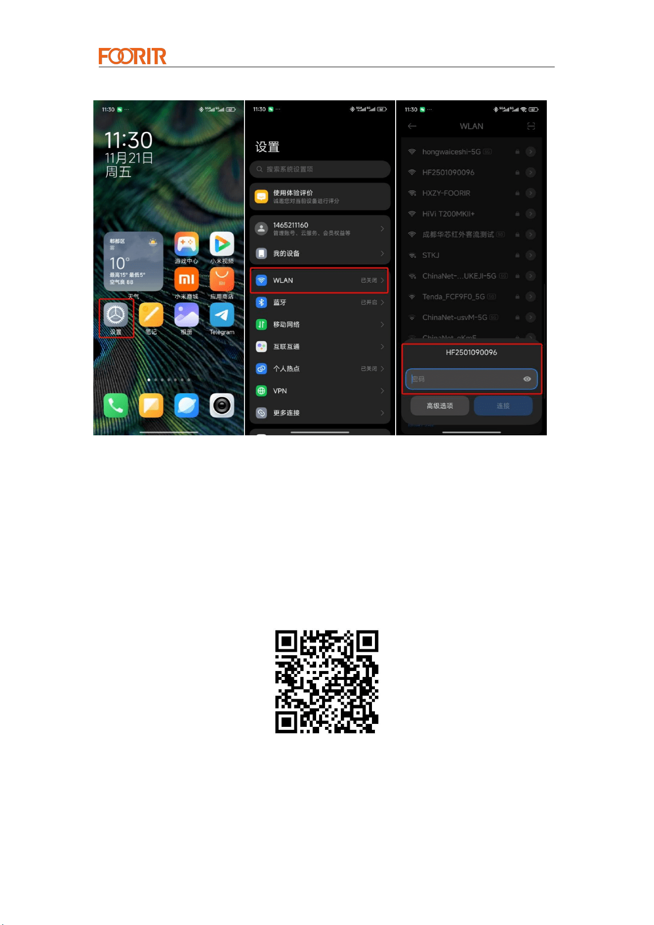
Network Cable
2. POE Power supply
If the POE switch connection conditions are available, the device can be directly
connected to the POE switch, and the power supply and networking can be provided
at the same time (no need to connect to DC power supply).
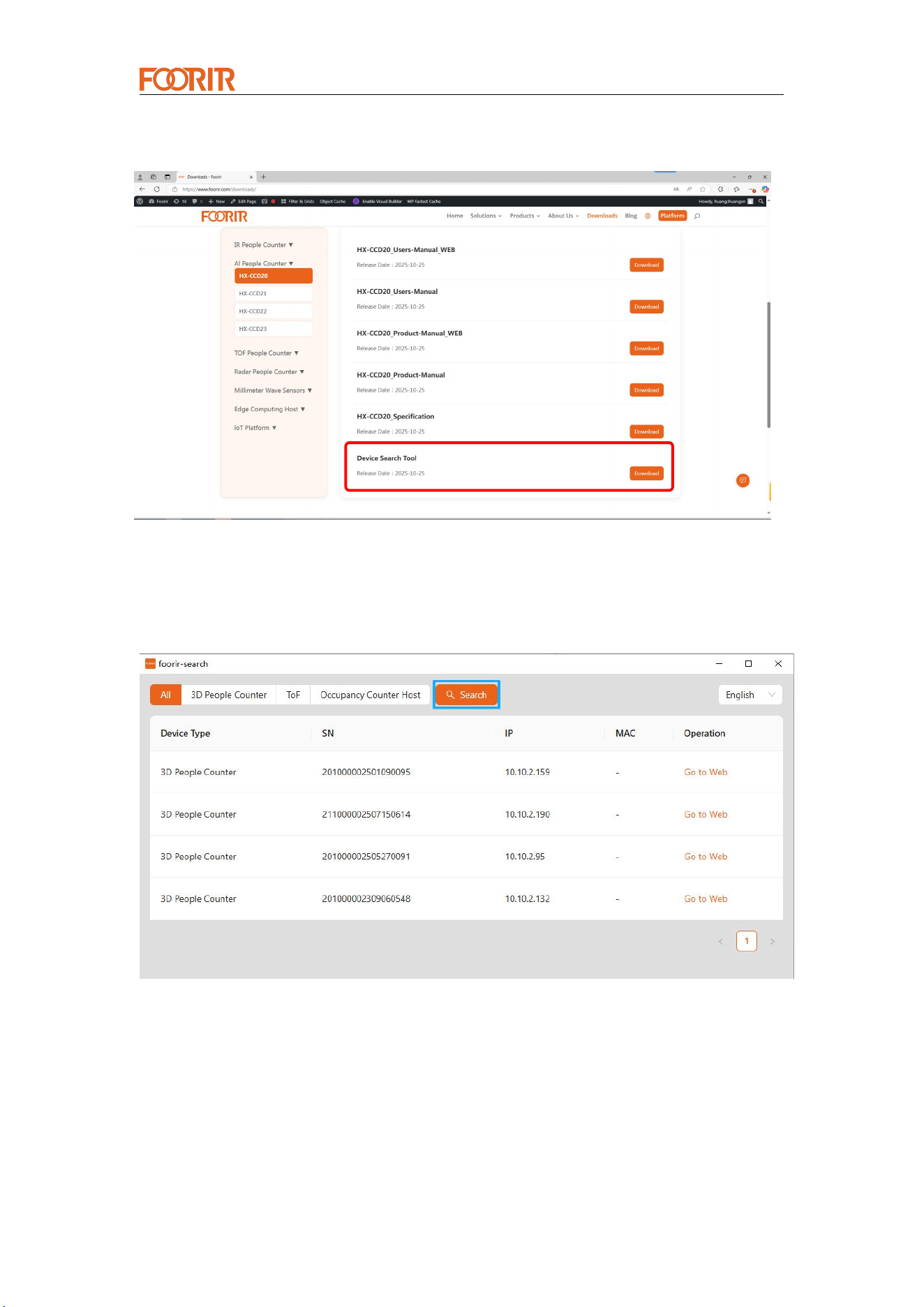
4.2 Connect Devices Using Hotspot
Open the Wi-Fi list on your computer (or phone) and search for the device's
hotspot: HF + the last 10 digits of the SN
Hotspot password: hf123456
PoE Switch
Smar t Cou nter Provide r
— 9 —
Open any browser and enter the access address: 192.168.4.10
Username: admin
Password: hf123456
4.3 Connect the Device Using a Network Cable
1.Download the accompanying tool "foorir-search" by scanning the QR code or from
the official website www.foorir.com.
Smar t Cou nter Provide r
— 10 —
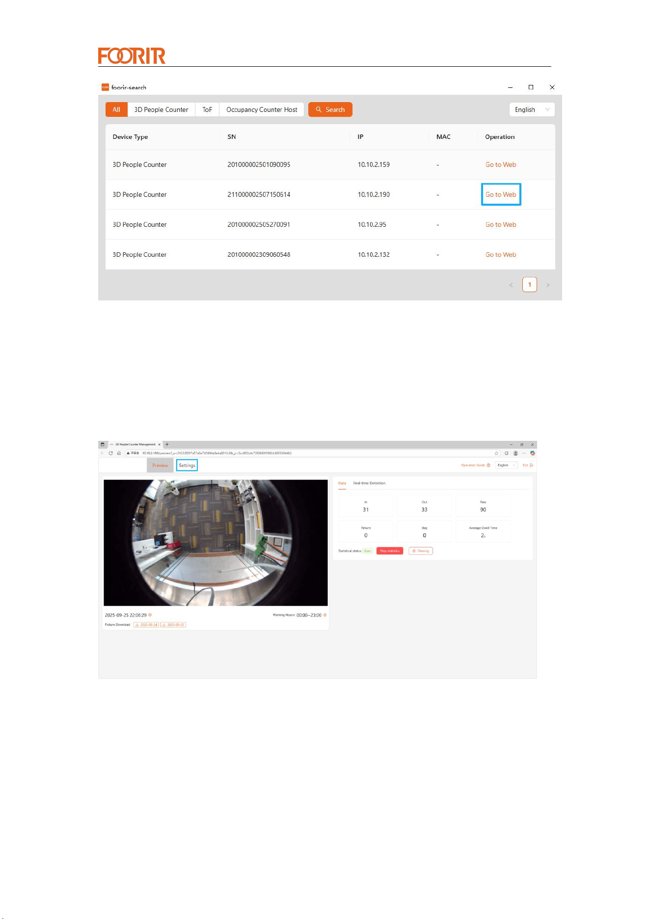
2. Open the supporting tool and scan for devices.
3. After searching for the device, enter the device configuration page.
Smar t Cou nter Provide r
— 11 —
5. Device Configuration Page Operations
5.1 Go to the Device Homepage and Select the "Settings"
Option
5.2 Set the Height Parameter
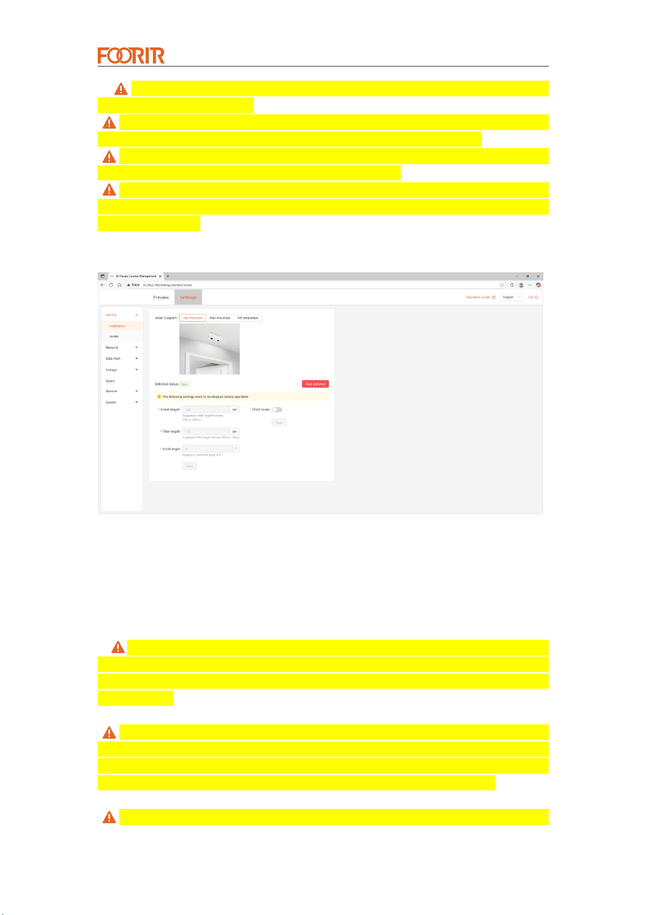
1. Settings are based on the actual installation; top mounting, side mounting, and
angled mounting are available (top-mounted horizontal installation is recommended);
2. Before setting parameters, the counting must be stopped;
Smar t Cou nter Provide r
— 12 —
3. Installation Height: The entered height must match the actual installation
height (error less than ±5cm);
Filter Height: Objects below this height will not be detected. This effectively
filters interference from objects. A height of 100-120cm is recommended;
Installation Angle: The optimal installation method is horizontal with a
0-degree angle. Inclined installation is not recommended;
Child Mode: When enabled, people below the child height but above the filter
height will be counted as children. If the child height setting is equal to the filter height,
it will be ineffective.
5.3 Set Detection Area and Detection Line
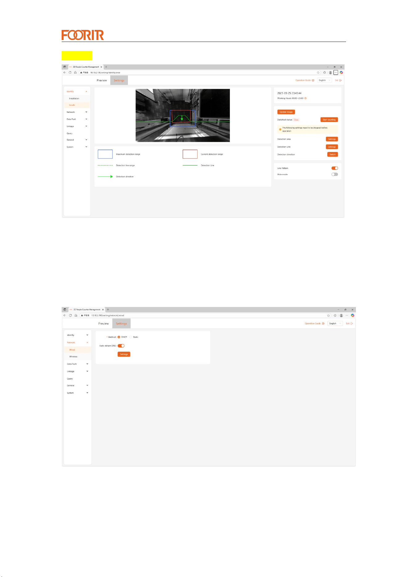
1. Before setting parameters, you need to stop counting;
2. Before setting, you can update the background image to ensure the lens is
unobstructed;
3. Detection Area: Blue represents the maximum detection range at the current
height, and red represents the current actual detection range. The detection range
cannot exceed the ground area and can be drawn according to the actual ground
passage area;
Detection Line: The detection line should not be too close to one side of the
detection area, and should be centered as much as possible. When setting, you need
to ensure that each entry and exit passes through the middle detection line (if the
sides of the detection line are missed, turn on the broken line mode below);
Detection Direction: The direction indicated by the arrow is the entrance
Smar t Cou nter Provide r
— 13 —
direction.
5.4 Network Settings (Optional)
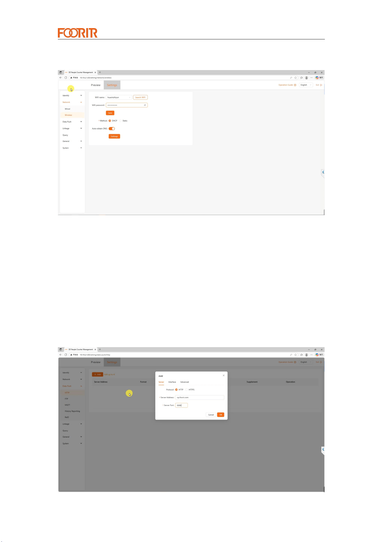
1. It is not recommended to use wired and wireless networks simultaneously. Unless
there are specific needs, it is advisable to use the default wired DHCP mode. If
manually setting a static IP address, ensure that the IP address is correct and usable,
and avoid IP conflicts with other devices.
2. The wireless network device only supports 2.4GHz WiFi. It cannot connect to 5GHz
or mixed-frequency WiFi.
Smar t Cou nter Provide r
— 14 —
3. After setting up the network, the device will restart, which takes approximately 1-2
minutes. Wait for the device to restart completely before refreshing the page.
5.5 Data Reporting Settings (Optional)
The device supports data reporting via HTTP, FTP, and MQTT; HTTP reporting is
recommended.
For example, using HTTP: only fill in the server address and port.
If using our cloud platform, simply set the server address: op.foorir.com; port: 8088.
For other settings, click on Interface Settings and Advanced Settings.
Smar t Cou nter Provide r
— 15 —
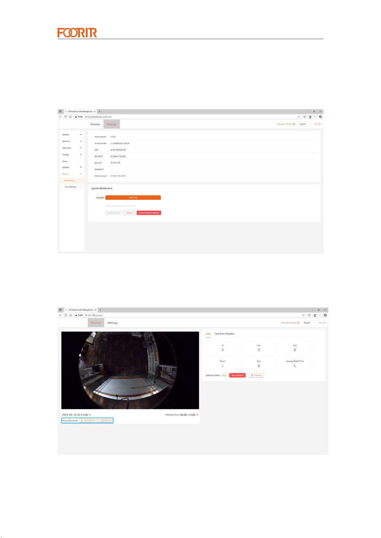
5.6 Equipment Upgrade (Optional)
Firmware upgrades are usually not required. When the supplier notifies you that an
upgrade is needed, you can upload the firmware provided by the supplier here to
upgrade the device. Before and after the upgrade, you need to confirm the device's
version number to confirm whether the upgrade was successful.
5.7 Map Collection (Optional)
If the count is inaccurate, you can click this button to automatically download the data
collected that day and submit it to the manufacturer for algorithm optimization.

Smar t Cou nter Provide r
— 16 —
6. Common Faults and Handling Methods
6.1 Device cannot be found in wired mode
Solution 1: Connect the computer and the device to the same LAN or connect with a
network cable, and change the IP address of the computer to DHCP.
Solution 2: Check the IP of the passenger flow device according to the network device
such as the router, change the computer to the same network segment, and manually
enter the IP connection.
6.2 Notes
1. The device automatically restarts at midnight every day by default. The local video
display data is cleared after the restart, and the local storage data of the device is not
cleared.
2. The heat dissipation of the device is on the back, if installed outdoors, it is
recommended to add a baffle above the device to avoid direct sunlight
3. Try not to have obstructions within the field of view of the lens
4. Wired connections always take precedence over wireless connections, so after
configuring wireless mode, you need to unplug the network cable.
5. WiFi only supports 2.4GHz, not support 5GHz.
6. Network latency affects the device's connection to the client
7. The installation height and angle must be filled in according to the actual one, if the
height angle is not correct, it will lead to inaccurate counting.
8. When setting the height, there can be no people or objects under the camera other
than the background.
Smar t Cou nter Provide r
— 17 —
Statement
Copyright © 2011- 2024 Chengdu Huaxin Zhiyun Technology Co., Ltd.
Copyright All Rights Reserved
Without the explicit written permission of Chengdu Huaxin Zhiyun Technology
Co., Ltd., no organization or individual may reproduce, copy, transcribe or
translate part or all of the contents of this manual without authorization, and
may not disseminate it in any way (electronic, photocopying, recording, etc.)
for profit-making purposes.
It is a registered trademark of Chengdu Huaxin Zhiyun
Technology Co., Ltd. All trademarks mentioned in this manual are owned by
their respective owners.
The product specifications and information mentioned in this manual are for
reference only. If there is any content update, no further notice will be given.
Unless otherwise agreed, this manual is only used as a guide, and the
statements made do not constitute any form of warranty.
Notice
The parameters used in the screenshots shown in this manual are only used as
setting examples for reference and may not be completely consistent with the
actual situation. Please set the parameters according to your actual needs.
The housing is prohibited from being disassembled during operation.
Anti-disassembly reminder: Be careful when manually disassembling the housing
of the device to avoid damage to the device. This is a Class A product. In a living
environment, this product may cause radio interference. In this case, the user
may need to take practical measures to deal with the interference.
Due to different software versions, the screenshots shown in this manual may not
be completely consistent with the device interface of the product you purchased.
Please configure your product according to the actual device interface.
If you find that there is a shortage or damage to any accessories, please contact
your local dealer in time. The product pictures/screenshots in this manual are for
reference only and are intended to help users install and configure the product.
Please refer to the actual product/actual interface for details.
For assistance, please contact:
Manufacturer: Chengdu Huaxin Zhiyun Technology
Co., Ltd.
Phone/WhatsApp:+86 18981978865
E-mail:info@foorir.com
Website: www.foorir.com
www.foorir.com
Phone/WhatsApp:+86 18981978865
E-mail:info@foorir.com
Address: Room 4021, Unit 1, Building 1, 88 Tianchen Road, High-Tech Zone, Chengdu, Sichuan, China

Smar t Cou nter Provide r
— 17 —
www.foorir.com
Phone/WhatsApp:+86 18981978865
E-mail:info@foorir.com
Address: Room 4021, Unit 1, Building 1, 88 Tianchen Road, High-Tech Zone, Chengdu, Sichuan, China
FCC Statement
Note: This equipment has been tested and found to comply with the
limits for a Class B digital device, pursuant to part 15 of the FCC
Rules. These limits are designed to provide reasonable protection
against harmful interference in a residential installation. This
equipment generates, uses and can radiate radio frequency energy and,
if not installed and used in accordance with the instructions,
may cause harmful interference to radio communications. However,
there is no guarantee that interference will not occur in a particular
installation. If this equipment does cause harmful interference to radio
or television reception, which can be determined by turning the
equipment off and on, the user is encouraged to try to correct the
interference by one or more of the following measures:
—Reorient or relocate the receiving antenna.
—Increase the separation between the equipment and receiver.
—Connect the equipment into an outlet on a circuit different from that
to which the receiver is connected.
—Consult the dealer or an experienced radio/TV technician for help.
This device complies with part 15 of the FCC Rules. Operation is subject
to the following two conditions:(1) This device may not cause
harmful interference, and (2) this device must accept any interference
received, including interference that may cause undesired
operation.
Any changes or modifications not expressly approved by the party
responsible for compliance could void the user's authority to operate
the equipment.
This equipment complies with FCC radiation exposure limits set forth for
an uncontrolled environment. This equipment should be
installed and operated with minimum distance 20cm between the
radiator & your body.