© 2023 GeoVision, Inc. All rights reserved.
Under the copyright laws, this m
anual may not be copied, in whole or in part,
without the written consent of GeoVision.
Every effort has been made to ensure that the information in this manual is
accurate. GeoVision, Inc. makes no expressed or implied warranty of any kind
and assumes no responsibility for errors or omissions. No liability is assumed
for incidental or consequential damages arising from the use of the information
or products contained herein. Features and specifications are subject to
change without notice.
GeoVision, Inc.
9F, No. 246, Sec. 1, Neihu Rd.,
Neihu District, Taipei, Taiwan
Tel: +886-2-8797-8377
Fax: +886-2-8797-8335
http://www.geovision.com.tw
Trademarks used in this manual: GeoVision, the GeoVision logo and GV
series products are trademarks of GeoVision, Inc. Windows is the registered
trademark of Microsoft Corporation.
M
arch 2023
Scan the following QR codes for product warranty and technical support
policy:
[Warranty] [Technical Support Policy]

i
Contents
Firmware and Software Compatibility................................................................................ ii
Chapter 1 Introduction ..................................................................................................... 1
1.1 Packing List ............................................................................................................. 2
1.2 Optional Accessories ............................................................................................... 3
1.3 Overview ................................................................................................................. 4
1.3.1 Bottom and Rear Views ............................................................................ 4
1.3.2 Terminal Block .......................................................................................... 5
Chapter 2 Getting Started................................................................................................. 6
2.1 Connecting the Device............................................................................................. 6
2.2 Restoring to Factory Default Settings ...................................................................... 7
2.3 Wall / Ceiling Mount................................................................................................. 8
Chapter 3 The Web Interface...........................................................................................10
3.1 Accessing the GV-Web Report Lite.........................................................................10
3.2 Setting the GV-3D People Counter V2....................................................................11
3.2.1 Selecting Detection Mode........................................................................11
3.2.2 People Counter Settings..........................................................................13
3.2.3 Report to Other Servers...........................................................................15
3.2.4 General Settings......................................................................................16
3.3 Accessing People Counting Data............................................................................23
3.3.1 Device .....................................................................................................24
3.3.2 Group ......................................................................................................25
3.3.3 Log ..........................................................................................................26
3.3.4 Query.......................................................................................................27
Chapter 4 GV-IP Device Utility.........................................................................................30
Appendix.............................................................................................................................32
Optimal Installation..........................................................................................................32
Detection Limitations.......................................................................................................33
ii
Firmware and Software Compatibility
The compatible versions of GV-VMS and GV-Web Report are listed below:
Model
GV-VMS
GV-Web Report
GV-3D People Counter V2 V1.03
or later
V18.1.1 or later
V3.0.1A or later
Note: For showing the people counting data on GV-VMS’s live view, see Video Analysis by
Camera in GV-VMS User’s Manual.
1
Chapter 1 Introduction
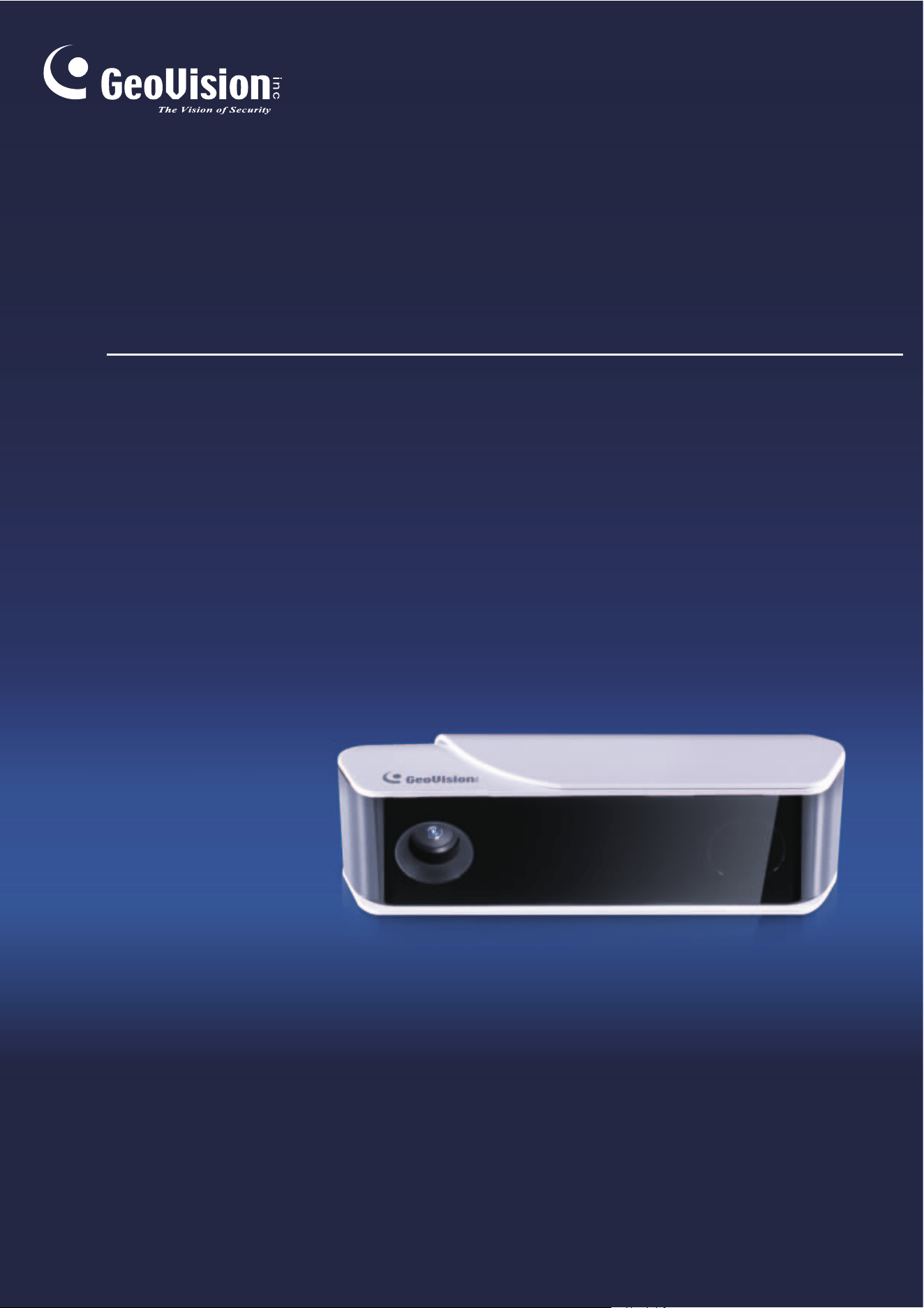
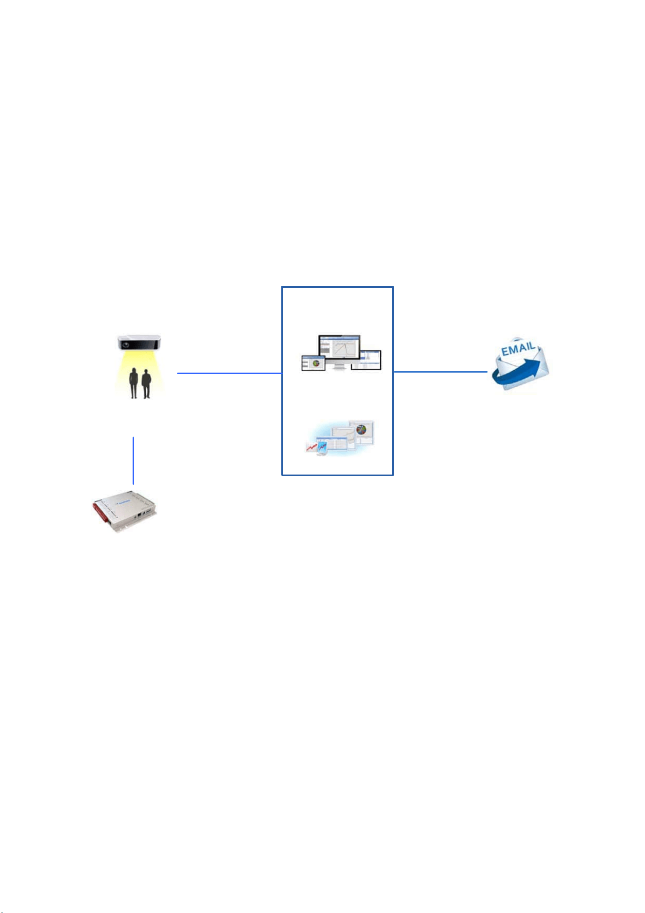
The GV-3D People Counter V2 can count and analyze the number of people passing by or
staying within a designated area with high precision and accuracy. With its Power over
Ethernet and user-friendly interface, the counter is simple to use and easy to install. You can
look up neatly compiled people counting data through its chart analyses with the support of
GV-Web Report Lite, a built-in Web interface. Additionally, the counter also supports the alarm
trigger when the predefined occupancy limit is reached.
GV-3D People Counter V2
People counting upon input trigger
Occupancy alarms triggered when the predefined limit is reached
GV-I/O Box
Infrared sensor to
detect people
Network Internet
Counting data,
charts and reports
Counting data and charts
Or
GV-Web Report
(Need S/W license)
GV-Web Report Lite
(Free)
Figure 1-1
2
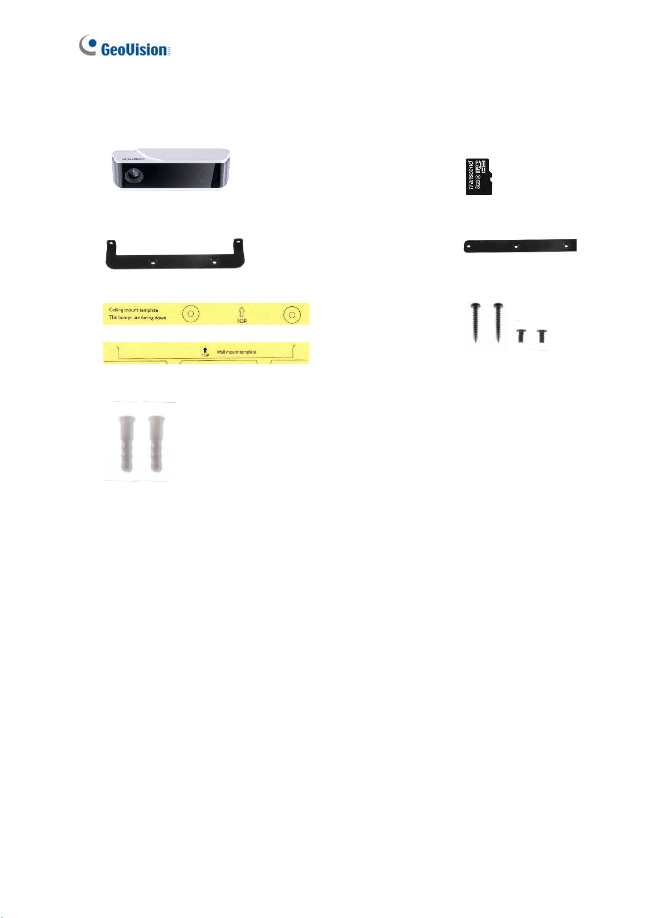
1.1 Packing List
1. GV-3D People Counter V2
2. SDHC Micro SD
card
3. Ceiling Mount Kit
4. Wall Mount Kit
5. Installation Sticker x 2 (Wall mount / Ceiling mount)
6. Screw x 4
7. Anchor x 2
8. Download Guide
9. Warranty Card
Introduction
3
1
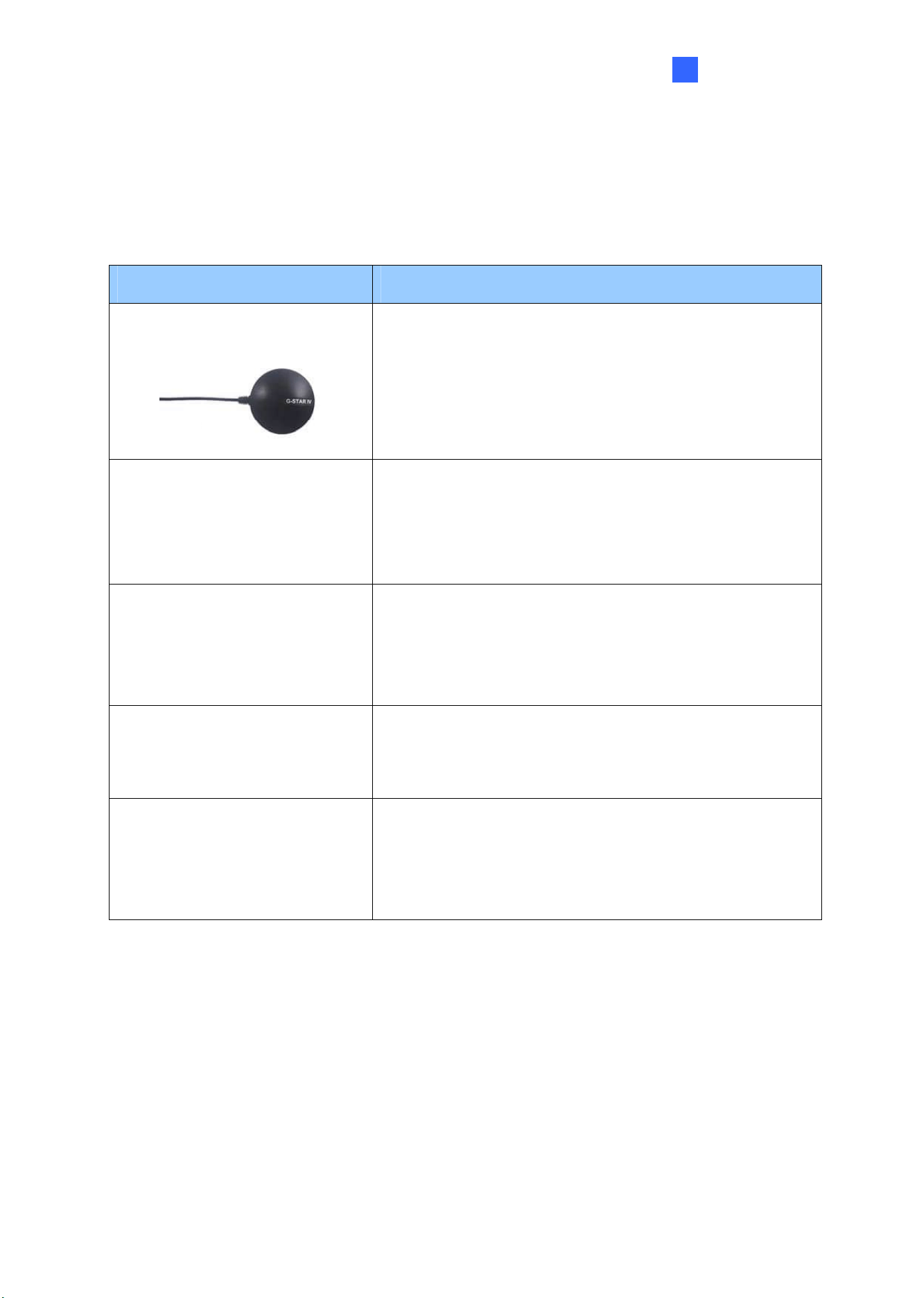
1.2 Optional Accessories
Optional accessories can expand the capabilities of your device. Contact your dealer for more
information.
Options Details
GV-GPS Receiver
Receive GPS signals for 3D People Counter positioning.
GV-IO Box
GV-IO Box extends the uses of an IP device by providing
input and output ports for triggering alarms such as light
or buzzer. GV-IO Box is available in different models with
different numbers of inputs and outputs.
GV-PoE Adapter
GV-PoE Adapter is designed to provide power to the IP
device through a single Ethernet cable. Adopting the PoE
adapter enables you to mount an IP device anywhere in a
building where power outlets are not available.
GV-POE Switch
GV-POE Switch is designed to provide power along with
network connection for IP devices, which is available in
various models with different numbers and types of ports.
GV-Web Report
Through a Web browser, the GV-Web Report keeps track
of and analyzes the people counting results and shows
the latitude and longitude from up to 1000 units of GV-3D
People Counter V2.
4
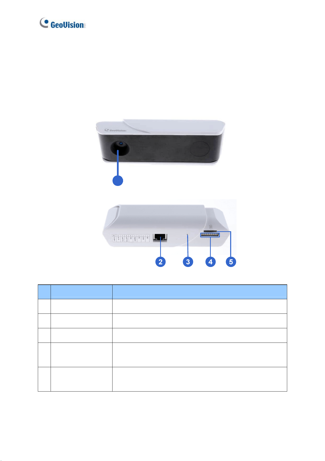
1.3 Overview
This section illustrates the components of GV-3D People Counter V2.
1.3.1 Bottom and Rear Views
1
Figure 1-2
No. Name Function
1. Lens Captures people’s image.
2 Ethernet Port A plug for PoE (IEEE 802.3af).
3 Default Button Resets all configurations to factory default settings.
4 Terminal Block
The connectors for the sensor input, alarm output and GPS
receiver, see 1.3.3 Auxiliary Device Connectors.
5 Memory Card Slot
Inserts a micro SD card (SD/SDHC/SDXC/UHS-I, Class 10) to
store recording data.
Introduction
5
1
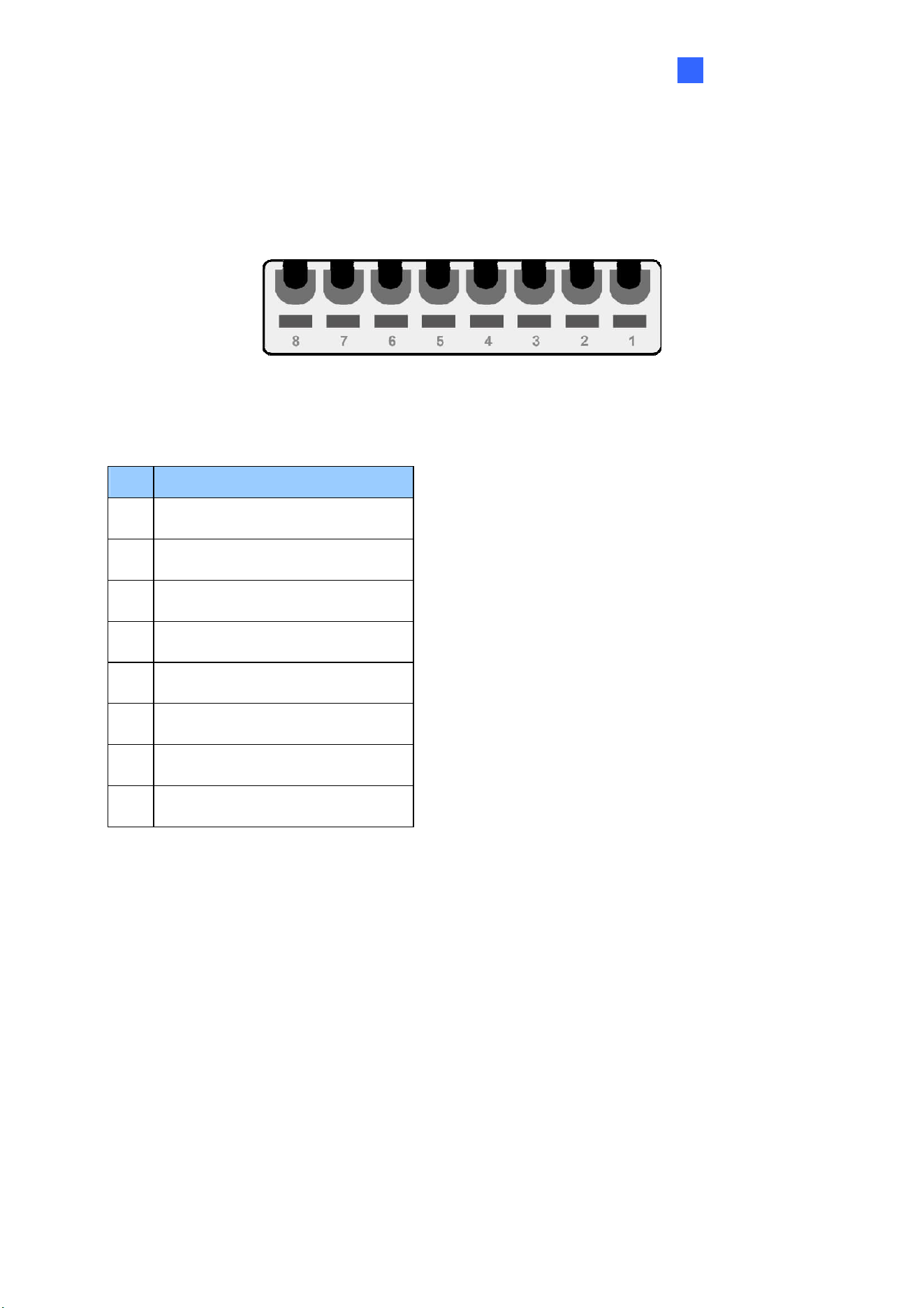
1.3.2 Terminal Block
The 8-pin terminal block, located on the rear panel, provides interfaces for connecting a digital
input, a relay output and a GV-GPS Receiver.
Figure 1-3
PIN Assignment
Pin Function
1. NO
2. COM
3. NC
4. Digital Input
5. Ground
6. UART RX for GV-GPS Receiver
7. UART TX for GV-GPS Receiver
8. DC 5V Out for GV-GPS Receiver
6
Chapter 2 Getting Started
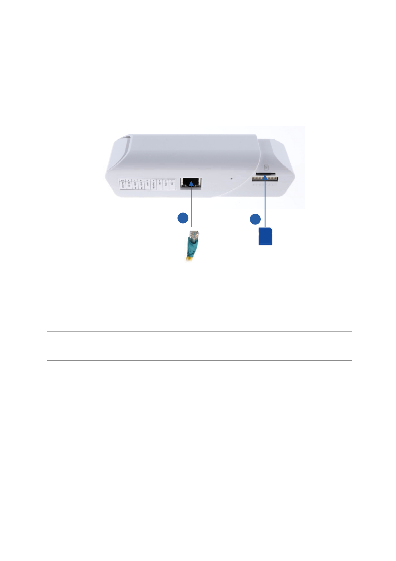
2.1 Connecting the Device
1
2
Figure 2-1
1. Plug a standard network cable or PoE to provide power supply and Internet connection.
2. Insert a micro SD card.
Note: GV-3D People Counter V2 only supports PoE. You may purchase GV-PA191 PoE
adapter to connect to your router.
Getting Started
7
2
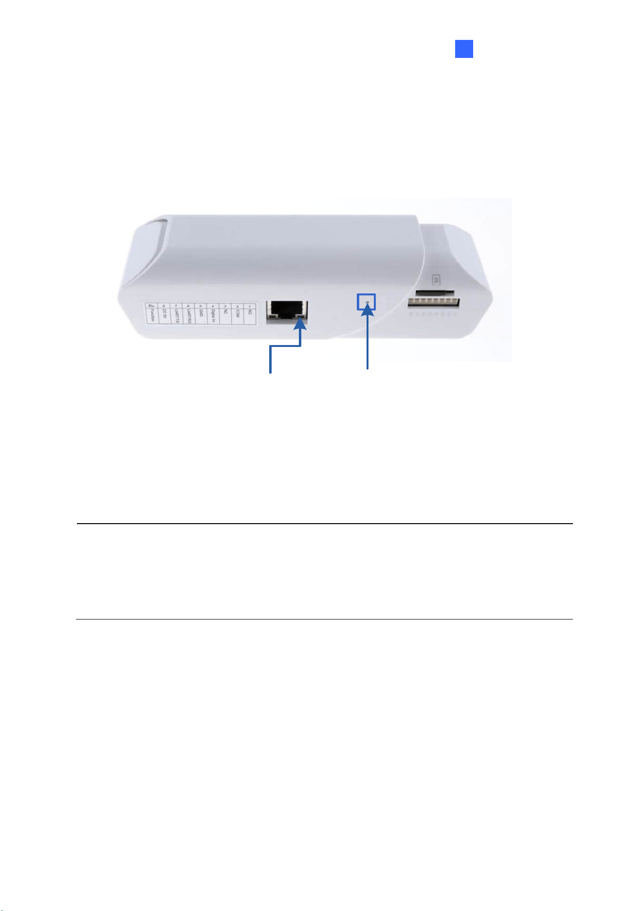
2.2 Restoring to Factory Default Settings
If for any reason the device is not responding correctly, you can restore it to its factory default
settings.
Green LED Default Button
Figure 2-2
1. Press and hold the Default button on the rear panel.
2. Release the Default button when the green LED stops blinking. The device reboots
automatically after loading the default settings.
Note:
1. The power supply should remain constant throughout the process of loading default.
2. You can also reset the device using GV-IP Device Utility. See Chapter 4 GV-IP Device
Utility.
8
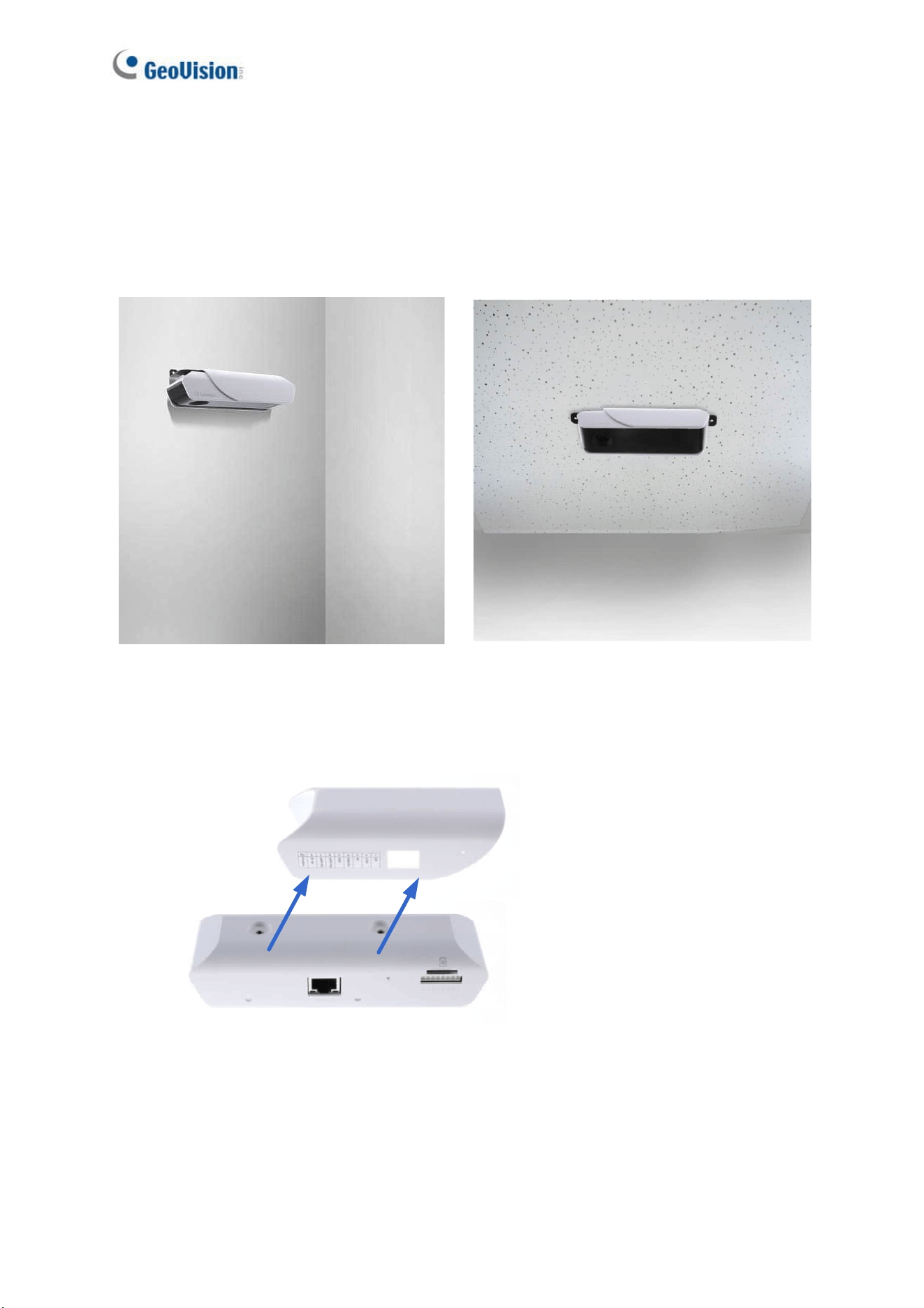
2.3 Wall / Ceiling Mount
You can use the Wall / Ceiling Mount Kit to mount the device on a desired location.
Wall Mount Ceiling Mount
1. Remove the device’s outer case.
Figure 2-3
Getting Started
9
2
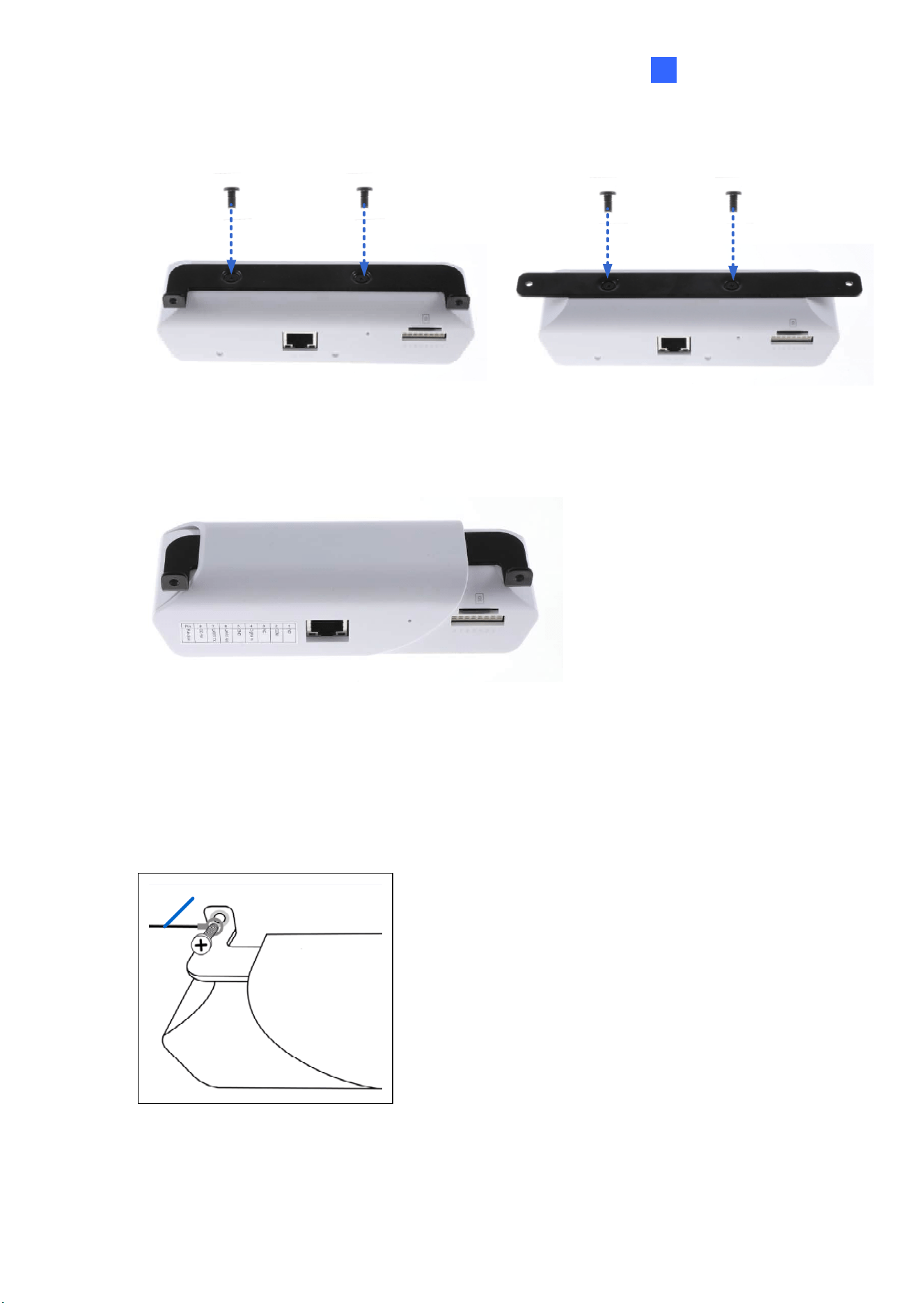
2. Secure the desired mounting kit to the designated position with 2 screws.
Figure 2-4
3. Reassemble the outer case.
Figure 2-5
4. Put the installation sticker to the wall with the arrow pointing up.
5. Drill 2 holes according to the sticker and insert the 2 screw anchors to the 2 holes.
6. Secure the device to the wall with 2 long screws.
7. Optionally install the ground wire with the screw as shown below:
Ground Wire
Figure 2-6
10
Chapter 3 The Web Interface
Once the GV-3D People Counter V2 is connected to the network, you can view counting data
by using its built-in Web interface, GV-Web Report Lite. When the device is connected to a
network with DHCP, it will be automatically assigned with a dynamic IP address. To look up
this IP address, use GV-IP Device Utility described in Chapter 4 GV-IP Device Utility.
However, if you do not have DHCP on your network, access the device by its default IP
address 192.168.0.10.
3.1 Accessing the GV-Web Report Lite
To access the device, Microsoft Internet Explorer 10 or above is required.
Two types of users can log into the device: Administrator and Guest. The Administrator has
full access to all system configurations, while the Guest can only access the Device, Group,
Log and Query pages.
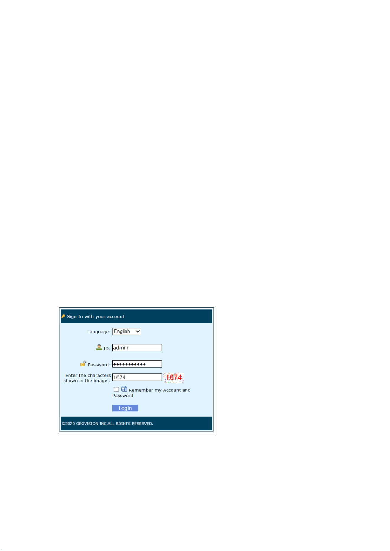
1. In your Web browser, type the IP address or the domain name of the device. This page
appears.
Figure 3-1
2. Select the Language.
3. Type the default ID and password admin.
4. Type the characters shown in the image and click Login. The Counting Signage page
appears, which will display real-time counting data after you set up the device.
The Web Interface
11
3
5. Click Setup on the top left corner to set up the device.
Figure 3-2
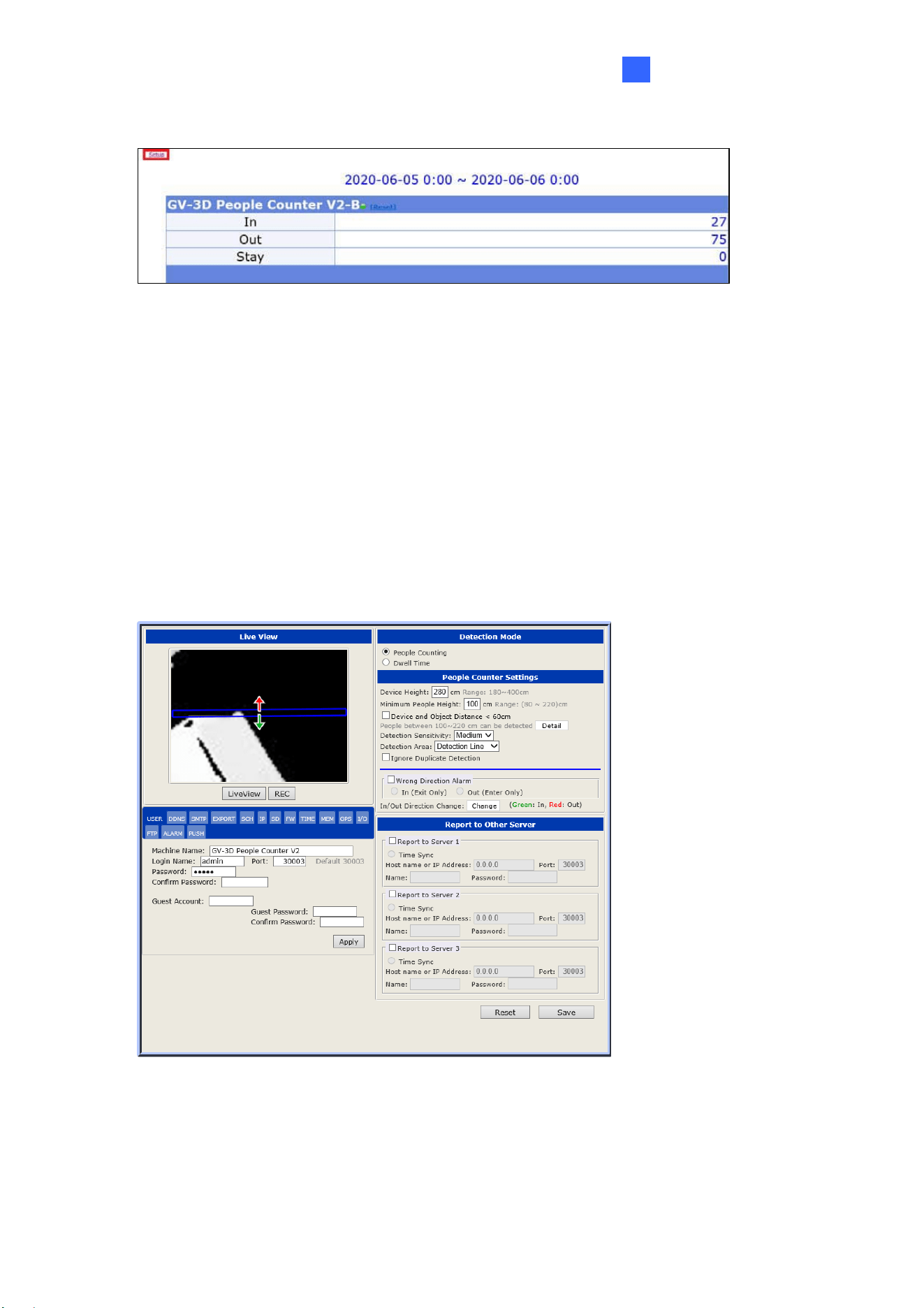
3.2 Setting the GV-3D People Counter V2
Once logging into GV-Web Report Lite, click Setup on the top left corner. In the Setup page,
you can configure the network settings of the device and set up for counting people entering
and leaving or record the dwell time of individuals staying within the designated area. Click
Reset to restore all configurations of this page to its factory default settings.
3.2.1 Selecting Detection Mode
Figure 3-3
[Detection Mode] Choose the desired detection mode from People Counting or Dwell Time.
People Counting: Counting and recording the number of people entering and leaving a
designated area based on the directions set.
12
Dwell Time: Record the dwell time of persons staying within a designated area.
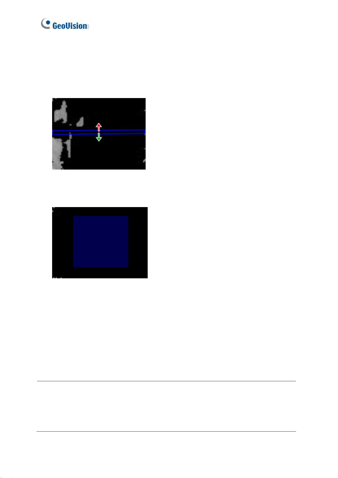
[Live View] Draw a box on the live view to mark the boundary of the detection zone.
For People Counting, people moving across the blue box in the direction of the red and
green arrows will be respectively counted as Out and In.
Figure 3-4
For Dwell Time, a timer is set on every person entering the designated area, which only
stops and records the dwell time upon the person leaving the area.
Figure 3-5
Live View: Click to see the black and white live image of the detection area captured by
the infrared sensor of the device.
REC: Record the live view for 30 seconds. Only one video can be stored in the SD card at
a time. The existing recording will be overwritten by the new recording.
Download Recorded File: You can download the recorded file and provide the recording
to the maintenance attendants for troubleshooting. The function appears after you record
live view.
Note:
1. People Counting and Dwell Time cannot function simultaneously.
2. For Dwell Time, make sure enough space is left outside the edges of the designated
area for determining the detected persons to be fully out of the area upon leaving.
The Web Interface
13
3
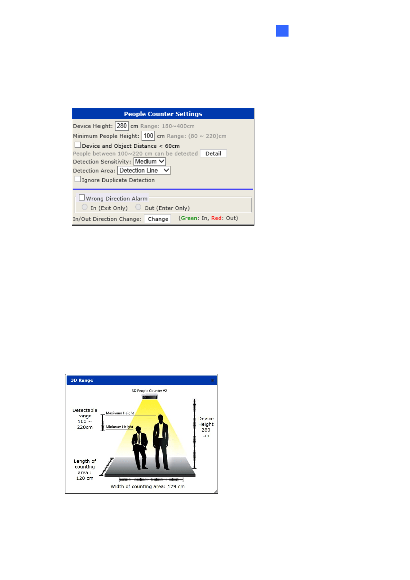
3.2.2 People Counter Settings
In this panel, you can modify people counter settings, detection settings, and reverse the
direction of entrance on Live View.
Figure 3-6
Device Height: Type the height of the installed device. Depending on the height where
the device is installed, the range of detectable height for people varies.
Minimum People Height: Type the minimum height for a person to be detected.
Device and Object Distance < 60 cm: Select this option when the distance of the
installed device and targets is lower than 60 cm. Once the option is selected, the detection
range will be reflected below.
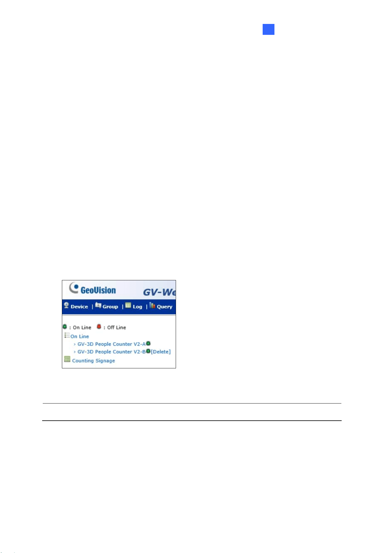
Detail: Click the button to see an illustration of the detectable range and the dimensions of
the detection area based on the height you specified.
Figure 3-7

14
Detection Sensitivity: Adjust the detection sensitivity at Low, Medium or High.
Detection Area: Select Detection Line and drag a line on the image to distinguish
directions for people moving across the defined line. Select Mask Area and drag image
masks to conceal certain area on the live view. People moving across the defined mask
position will not make a count.
Ignore Duplicate Detection: Only for People Counting, enable to minimize repeated
counting of people who lingers around the detection zone. Once enabled, a mask appears
on the live view and people who lingers within the defined area only make a single count.
Wrong Direction Alarm: Only for People Counting, enable if the detection area is for exit
only or entrance only, a wrong direction count will be recorded in GV-Web Report Lite
under Counting Signage when people are detected to be moving in the wrong direction.
See 3.3.1 Device.
In/Out Direction Change: Only for People Counting, to reverse the direction of the In
and Out arrows in the Live View screen, click the Change button.
After configuring people counter settings, click the Save button.
The Web Interface
15
3
3.2.3 Report to Other Servers
You can send people counting data to up to three other GV-Web Report Lite servers and / or
GV-Web Report for data collection and analyses. To query data collected by the GV-Web
Report Lite, see 3.3 Accessing People Counting Data.
1. Select Report to Server.
2. Type the IP address of the GV-Web Report (Lite).
3. Modify the default Port 30003 if necessary.
4. Type the Name and the Password to access the GV-Web Report (Lite).
5. If you click Time Sync, the current device time will be synchronized with the selected
server.
6. Click Save.
Once you click Save, your device (e.g. GV-3D People Counter V2-B) will send counting data
to the designated device (e.g. GV-3D People Counter V2-A) and the Machine Name of your
device will appear in the left menu of the designated device.
Figure 3-8
Note: GV-3D People Counter V2 is only compatible with GV-Web Report V3.0.0.0 or later.
16
3.2.4 General Settings
The panel below the Live View allows you to manage various settings, such as network,
device settings and more, from the following tabs: User, DDNS, SMTP, Export, SCH, IP, SD,
FW, Time, MEM, GPS, I/O, FTP, ALARM and Push.
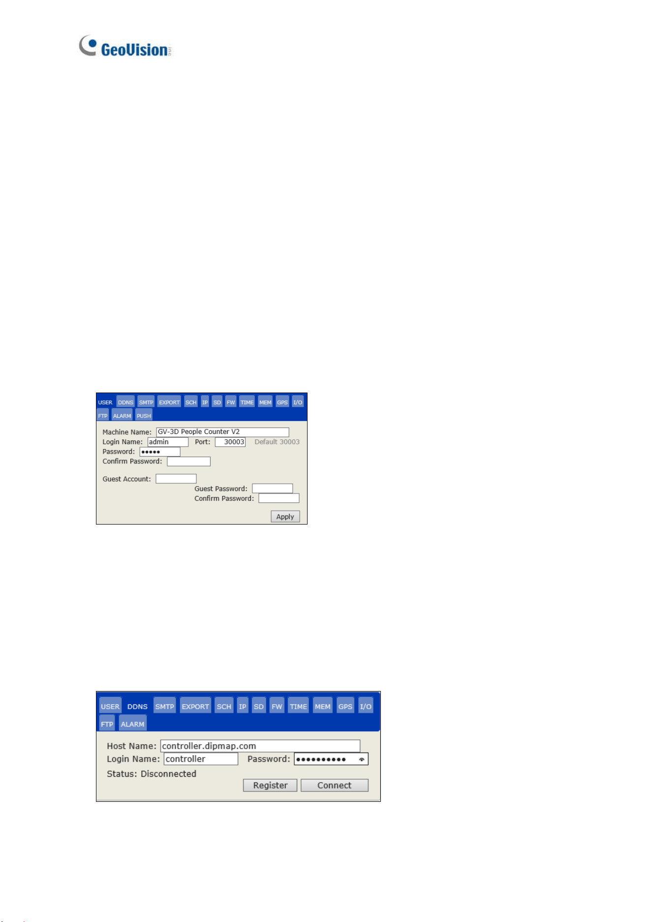
[User]
Machine Name: Modify the display name of the device.
Login Name / Password: Modify the login credentials of the administrator account. The
default login name and password are admin.
Port: Modify the port or keep the default value 30003. When connecting to another server,
the device must use the same port as the server.
Guest Account / Password: Modify the login credentials of the guest account. The
default login name and password are guest.
Figure 3-9
[DDNS]
DDNS (Dynamic Domain Name System) provides a convenient way of accessing the device
with a dynamic IP address. DDNS assigns a domain name to the device, so that the
Administrator does not need to check if the IP address assigned by DHCP Server or ISP (in
xDSL connection) has changed.
Figure 3-10
The Web Interface
17
3
1. Click Register to register a GeoVision DDNS Server or apply for a host name from other
DDNS service provider’s website.
2. Type the Host Name used to connect to the device.
3. Type the Name and Password used to enable the service from the DDNS.
4. Click Connect.
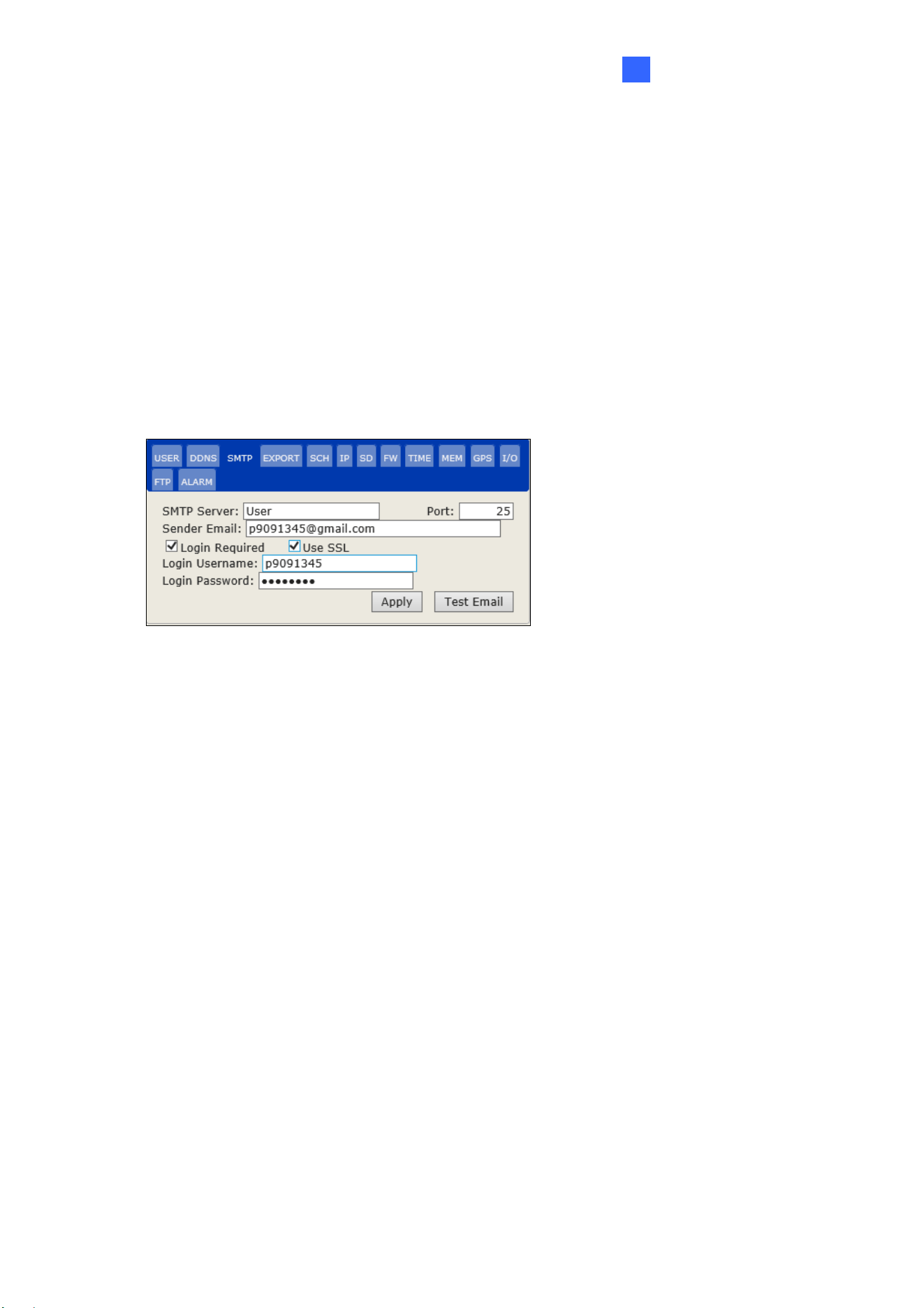
[SMTP]
You can send a report of counting results from a specified E-mail address. For this function to
work, make sure the mail server is properly configured, and the Enable Auto Export function
in the Export tab is enabled.
Figure 3-11
SMTP Server: Type your SMTP Server’s URL address or IP address.
Port: The default port for most SMTP servers is 25. However, webmail Yahoo and Hotmail
generally use differently SMTP port. In this case, check your e-mail provider for the SMTP
port number.
Sender Email: Type the sender’s e-mail address.
Login Required: If your mail server needs login authentication, select the checkbox and
type your login username and password in the Login Username and the Login
Password fields.
Use SSL: Select this option if the SMTP server needs a secure connection.
Test Email: Click to send a test e-mail to the specified e-mail address. Make sure to
configure the E-mail address in Recipient E-mail under Export as well.
18
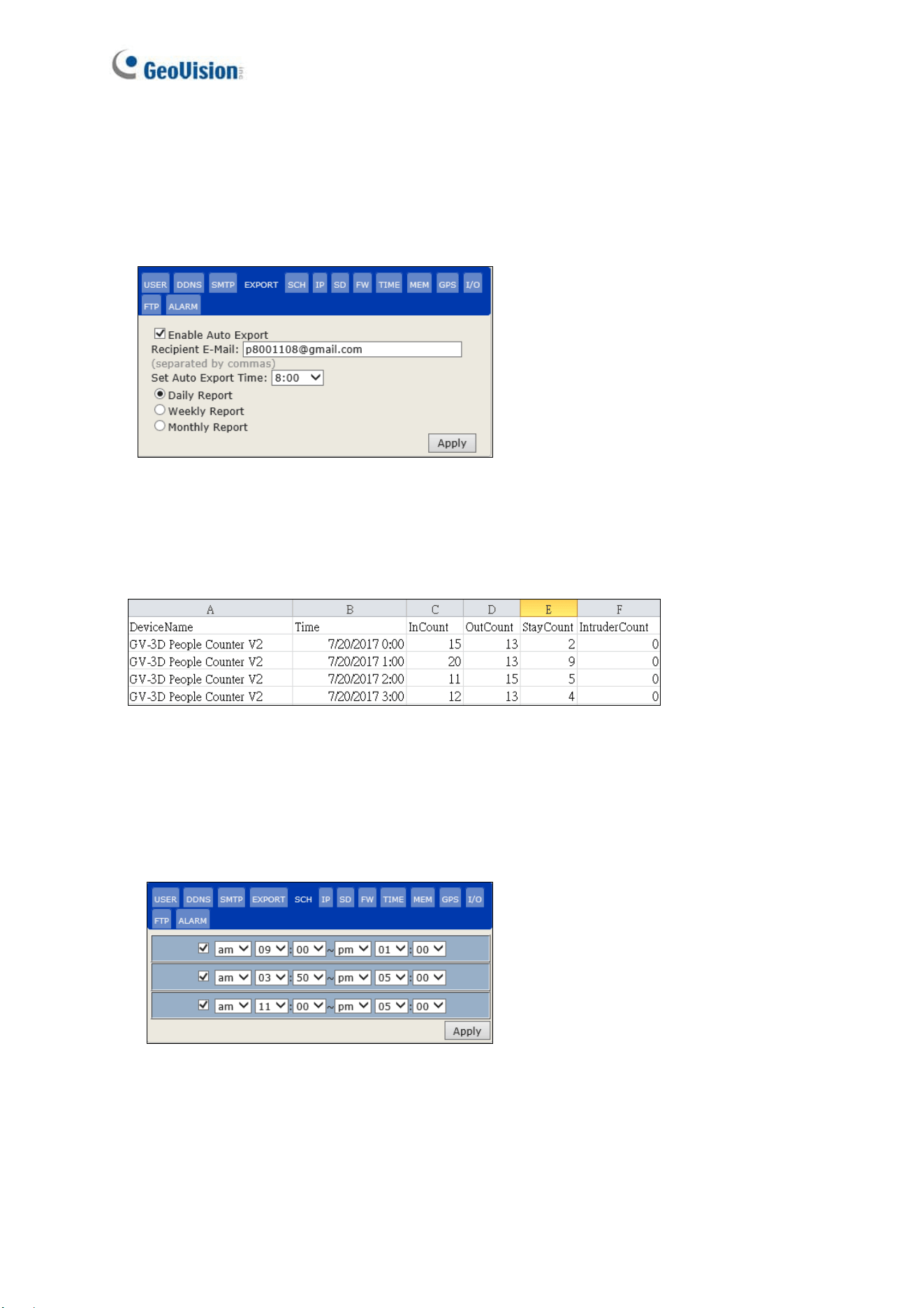
[Export]
To automatically receive an e-mail report of the counting data, select Enable Auto Export
and type the Recipient E-mail. Specify the time to receive the report from the Auto Export
Time drop-down list and click Apply. For this function to work, make sure the mail server is
properly configured in the SMTP tab.
Figure 3-12
After completing the Export settings, you shall receive the report in a zip file at the appointed
time. The format of the report is shown as the figure below.
Figure 3-13
[SCH]
To enable people counting only during the specified period within a day, click the checkbox
and specify a time period. You can set up to 3-time frames.
Figure 3-14
The Web Interface
19
3
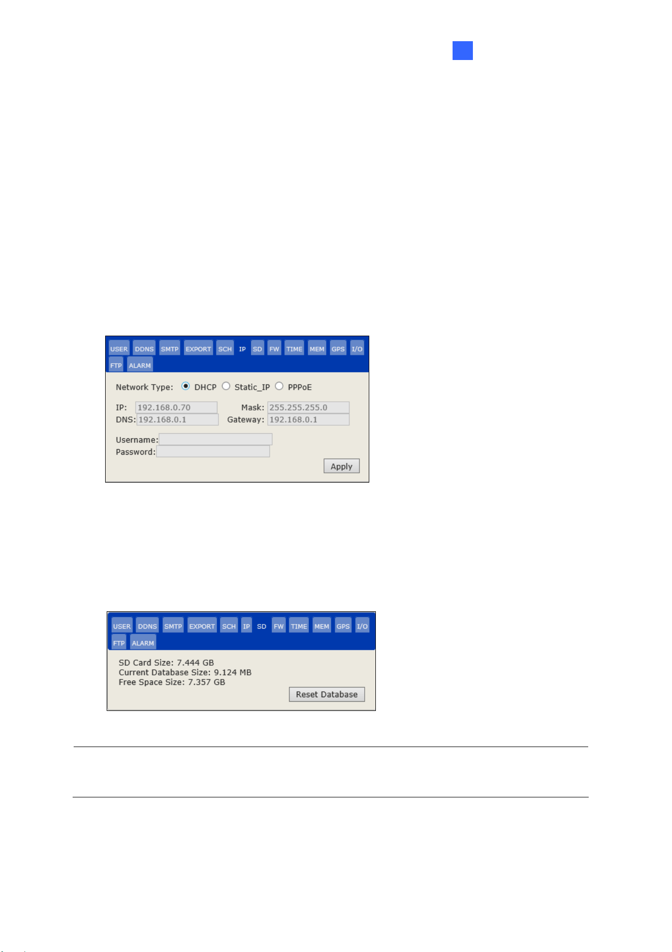
[IP]
According to your network environment, select a Network Type.
DHCP: Select if your network environment has a DHCP server which can assign a
dynamic IP to your device. By default, this option is enabled.
Static IP: To set up a fixed IP address, type the IP address, subnet Mask, DNS and
Gateway of the static IP.
PPPoE: Establish the connection to your ISP. In Username / Password, Type the
username and password provided by the ISP to establish the connection. However, if the
IP address provided by your ISP is dynamic, use the DDNS function to obtain a domain
name linking to the unit’s changing IP address before enabling the PPPoE function. For
details on Dynamic DNS Server Settings, see DDNS in 3.2.4 General Settings.
Figure 3-15
[SD]
You can see the size of the inserted SD card, size of space occupied by current database and
size of free space. To clear the content of the SD card, click Reset Database.
Figure 3-16
Note: Make sure to insert a functioning SD card in order for the People Counting function to
work.
20
[FW]
GeoVision periodically releases updated firmware on the website
. Upload the new firmware
and click Apply.
Figure 3-17
Note: Make sure to insert a functioning SD card before firmware upgrade. If the SD card is
damaged, you will see an error message “open db failed” after firmware upgrade.
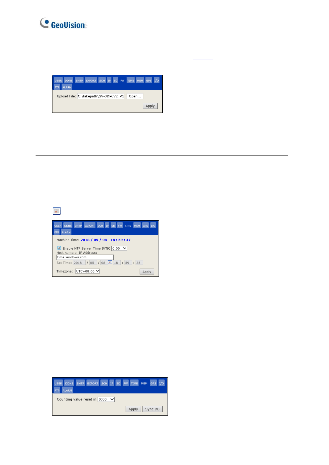
[TIME]
To automatically synchronize the device time with the server time every day, select Enable
NTP Server Time SYNC. From the drop-down list, specify the time period when the
synchronization is to take place every day. To manually set the device time, click the calendar
icon
to select the date, type the specific time into the time field, and click Apply.
Figure 3-18
[MEM]
By default, the counting result is reset to zero at 12:00 midnight everyday. To set a different
reset time, specify the time period from the drop-down list next to Counting value reset and
click Apply. After modifying the reset time, you can also click Sync DB and the GV-Web
Report Lite synchronizes the counting results to the last updated result. For example, if you
change the reset time to 19:00 and click Sync DB, the counting results accumulated from the
previous 19:00 will be displayed in the Counting Signage of GV-Web Report Lite.
Figure 3-19
The Web Interface
21
3
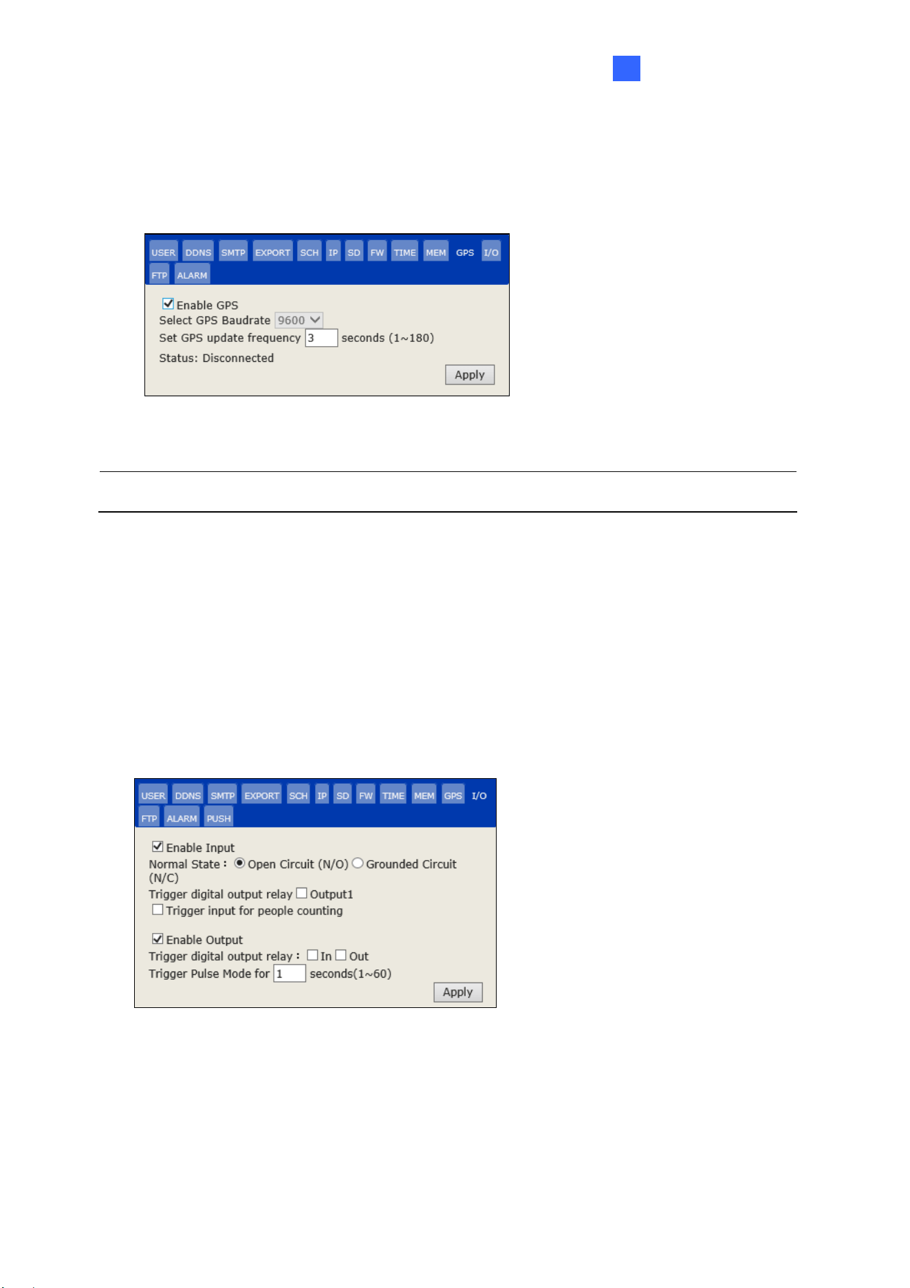
[GPS] Only for People Counting
Select Enable GPS to activate GV-GPS function. You can set the frequency for GV-3D People
Counter V2 to download GPS information from GV-GPS. The interval is between 1~180
seconds. The connection status (Connected / Disconnected) is displayed in Status.
Figure 3-20
Note: The GV-GPS data is only accessible and supported by GV-Web Report V2.2.6.0.
[I/O] Only for People Counting
Enable Input / Output: Enable the input and output device.
Normal State: Set an input state to trigger actions.
Trigger digital output relay: Trigger an output upon detection of a related input.
Trigger input for people counting: Start people counting upon the input trigger.
Trigger Pulse Mode for x seconds (1~60): Type the amount of time the triggered output
lasts.
Figure 3-21
22
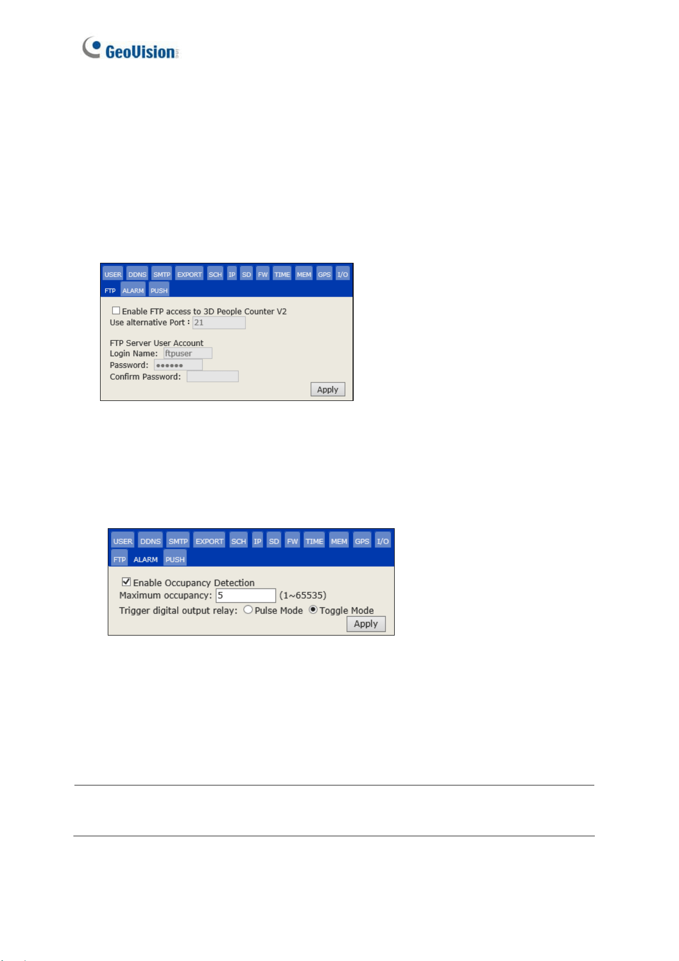
[FTP]
The GV-3D People Counter V2 can act as an FTP server for external IP devices to download
the recorded files saved on the memory card.
Enable FTP access to the GV-3D People Counter V2: Allow external IP devices to
access the device as a FTP server.
Use Alternative Port: The default port is 21.
Under FTP Server User Account, type the default username ftpuser and password 123456
when you are prompted for authentication.
Figure 3-22
[ALARM] Only for People Counting
Click Enable Occupancy Detection to trigger an alarm output as the number of occupants
exceeds the limit of Maximum Occupancy, ranging from 1~65535 people.
Figure 3-21
Pulse Mode: The triggered output duration is as set up in the I/O tab (see Figure 3-18).
Toggle Mode: The triggered output will last as long as the number of occupants is greater
than or equal to the Maximum Occupancy.
Note: The counting data of multiple devices can be combined to trigger occupancy alarms.
For details, see 3.3.2 Group.
The Web Interface
23
3
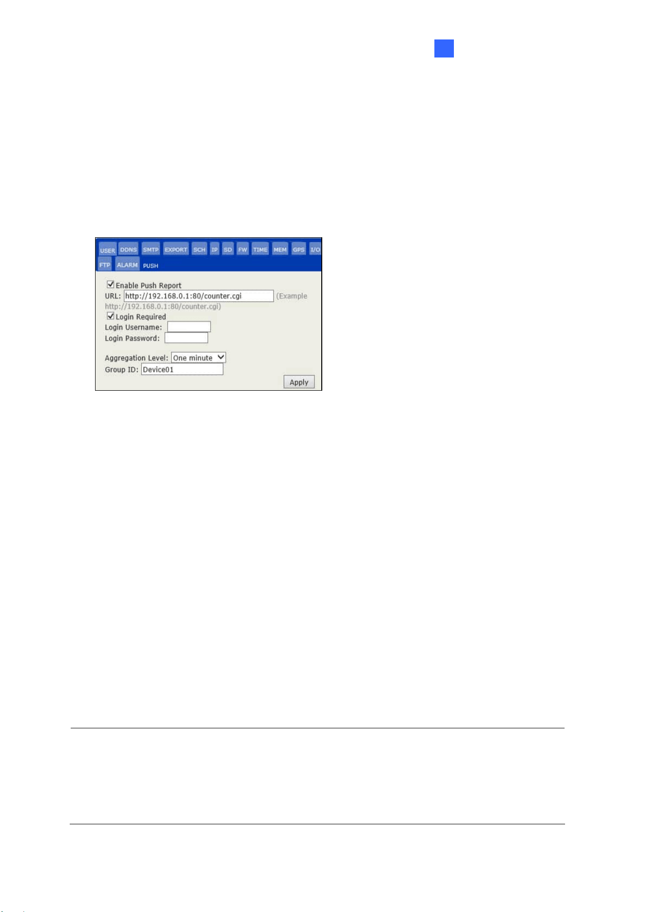
[PUSH]
Select Enable Push Report and type the URL of the server you want to send the notification
data to along with its port number.
Login Required: Select to optionally set a Login Username and Password that needs to
be matched on the server for receiving data from GV-3D People Counter V2.
Aggregation Level: Select the time interval between sending each notification data.
Group ID: Set an ID for the server to determine which device the data is being sent from.
Figure 3-24
3.3 Accessing People Counting Data
After the GV-3D People Counter V2 is properly configured and the data collection process
begins, you can access the following pages for the people counting data in the format of
tables, graphs and charts:
Device: Display the real-time counting data in tables and bar charts from all connected
devices. The data is updated every minute.
Group: Allows you to organize the connected devices into Groups and view the data of
created groups.
Log: Allows you to view the data of a specified time period from the selected device.
Query: Provides counting data on the daily, weekly, monthly and yearly graphs and
tables.
Note:
1. When detection mode is set as Dwell Time, only the persons entering the designated
area are counted and displayed as In.
2. When detection mode is set as Dwell Time, Log and Query functions are not supported.
24
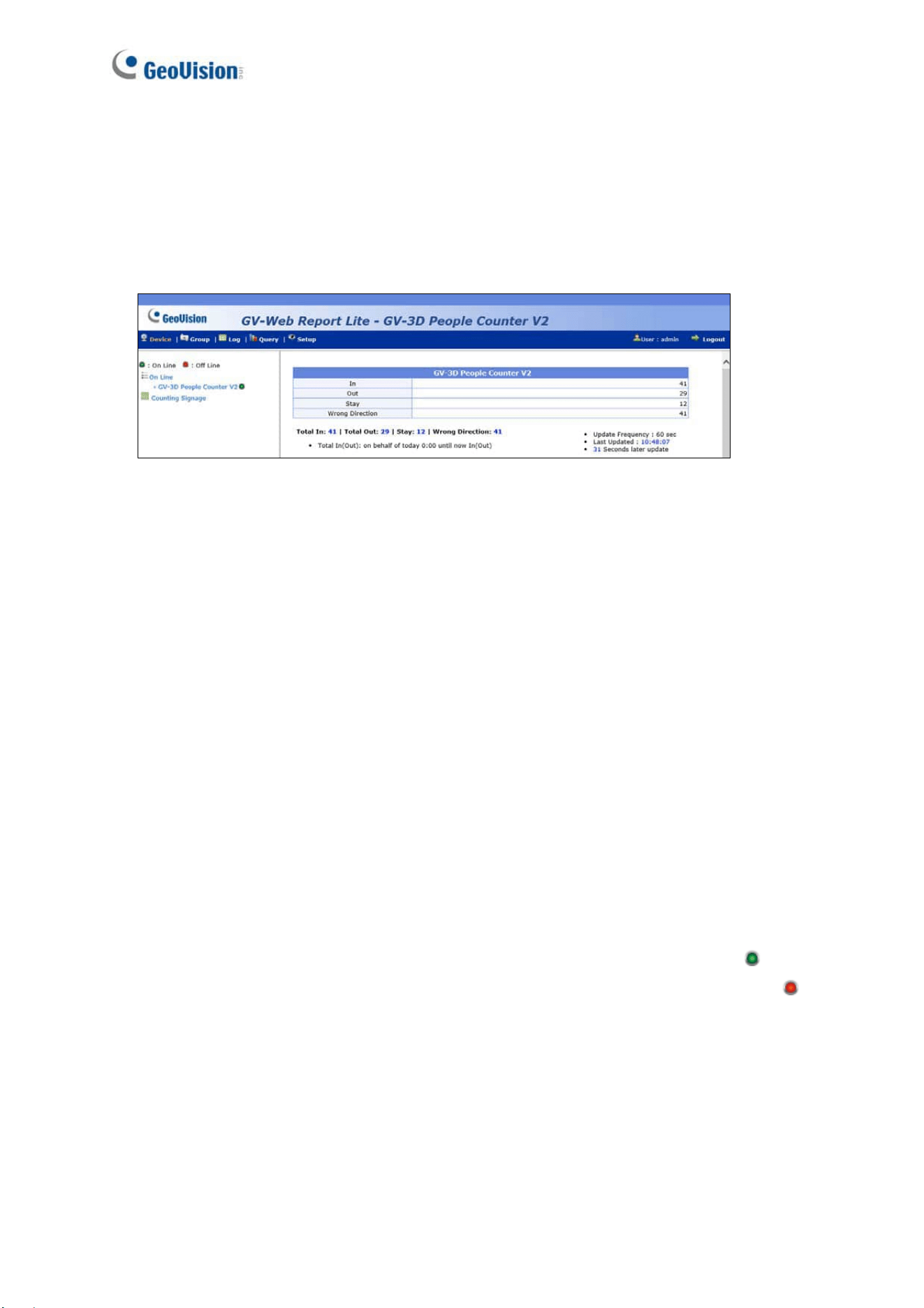
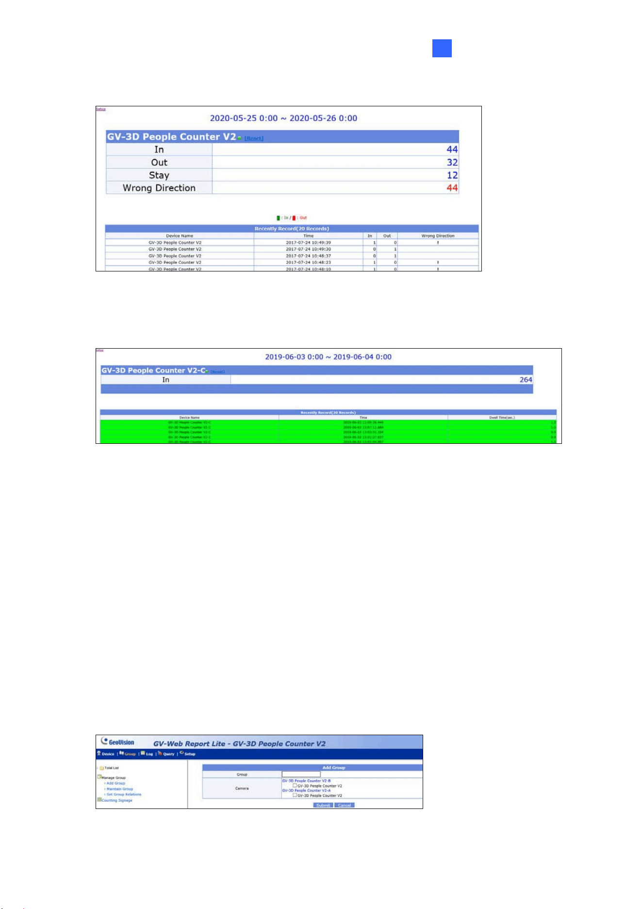
3.3.1 Device
In Device, you can see the total number of people entering, exiting, and staying in an indoor
space, along with the total number of people who moves in the wrong direction in the form of
tables and bar charts. The data on this page is updated every minute from all connected
devices.
Figure 3-25
The tables on the main page show the following information for each GV-3D People Counter
V2.
In: The number of people entered on that day since 0:00 or since the start of schedule.
Out: The number of people exited during the day.
Stay: The number of people remaining. That is subtracting the number of Out from the
number of In.
Wrong Direction: The number of people moving in the wrong direction. To display this
information, the Wrong Direction Alarm option in Setup must be enabled. See 3.2.2
People Counter Settings.
The Total In, Total Out, Stay and Wrong Direction below the tables are the total number of
people counted from all connected GV-3D People Counter V2.
On the left menu, these options are available:
Total List: Select a device to access its individual counting data. A green figure
indicates that the device is connected to GV-Web Report Lite; otherwise a red figure
appears.
Counting Signage: Access the number of people counted on the day and the recent
records of entries and exits. When people move in the wrong direction, the alarm will
sound. The recent 20 records are listed at the bottom, highlighted in one of the following
colors:
Green (number of In detected > number of Out detected)
The Web Interface
25
3
Red (number of Out detected > number of In detected)
Figure 3-26
For Dwell Time, only the persons entering the designated area are recorded, which
are displayed as In with their stay times shown.
Figure 3-27
3.3.2 Group
In Group, you can organize the connected GV-3D People Counter V2 into a hierarchy of
groups and view the counting data of each device in a set group. The counting data of all the
devices within the group will be combined to trigger occupancy alarms and computer alarms
upon reaching or exceeding the predefined maximum occupancy.
To set up a group:
1. Log in the devices you wish to add and follow the steps in 3.2.3 Report to Other Servers to
connect them to a designated device.
2. Log in the designated device. Click Add Group from the left menu. This page appears.
Figure 3-28
26
3. Name the group.
4. Select devices to be included in the group.
5. Click Submit.
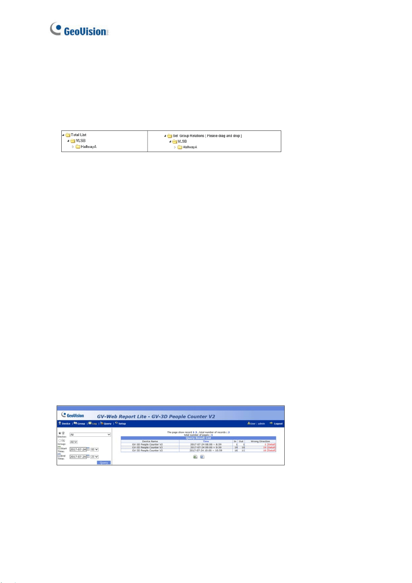
6. To organize multiple groups into hierarchy, click Set Group Relations in the left menu.
Drag and drop a group under another group to make it a subordinate group.
Figure 3-29
To trigger occupancy alarms when the predefine limit is reached for the grouped
devices:
1. To set up an output alarm, click the I/O tab. See Figure 3-21.
2. To enable occupancy detection and define the limit, click the ALARM tab. See Figure
3-23.
On the left menu of the Group page, you can find these options:
Total List: Access the counting data of the set groups updated every minute.
Counting Signage: Access real-time counting data of the set groups. When the value of
Stay reaches or exceeds the predefined maximum occupancy, a warning message
display on the page, as well as trigger occupancy alarms and computer alarms.
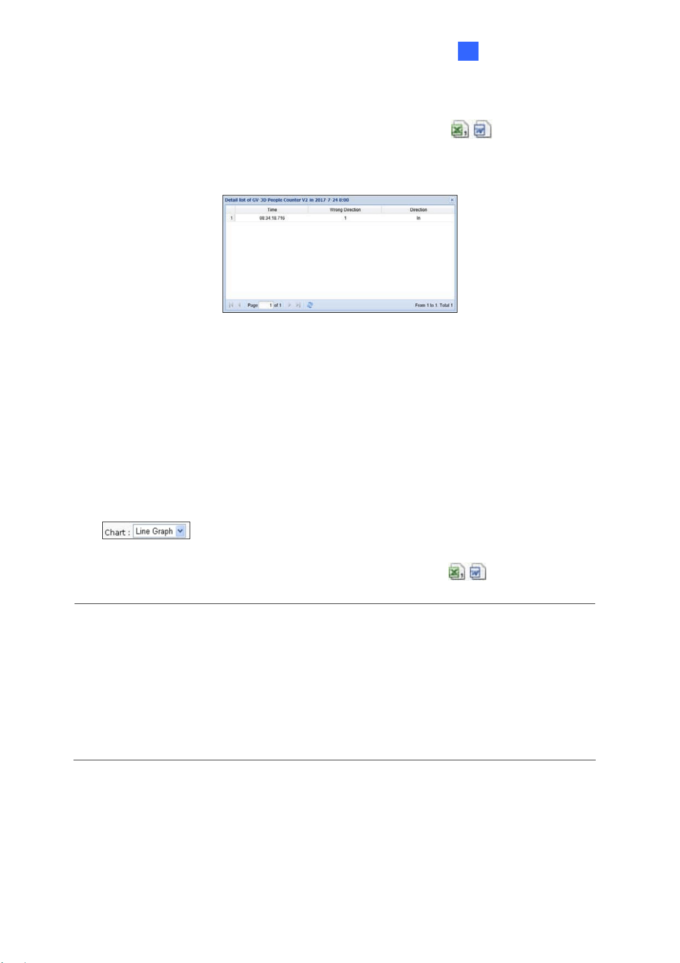
3.3.3 Log
In Log, you can view the data of a specified time period, listed on an hourly basis, from a
specific GV-3D People Counter V2 or group.
Figure 3-30
To search the log data:
1. Select a Device or a Group.
2. Specify Start Time and End Time of the log data.
The Web Interface
27
3
3. Click Query to display the search results.
To back up the search results in EXCEL or WORD, click the icons
at the bottom of
the Query Result List. Under Wrong Direction, you can click [Detail] to see the time of the
wrong entry or exit during that hour.
Figure 3-31
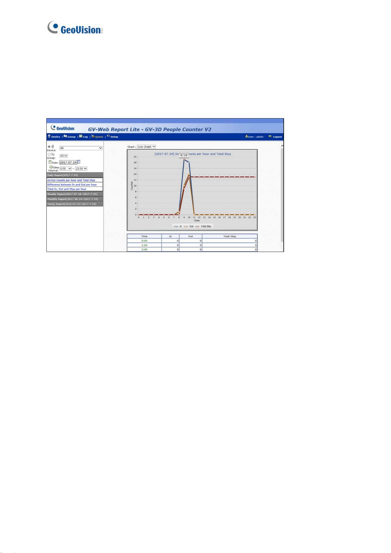
3.3.4 Query
In Query, the counting data is provided on the daily, weekly, monthly and yearly graphs and
tables.
To search the counting data, select a Device or a Group, specify a date, and select the
options below. To view the data in bar graph, line graph or pie chart, use the Chart drop-down
list
.
To back up the search results in EXCEL or WORD, click the icons
at the bottom of the
Query Result List.
Note: Pie chart is not available for the following types of data:
In/Out Counts per hour and Total Stay
Total In, Out and Stay per Hour
In Counts per Hour
Out Counts per Hour
Total Stay per Hour
[Daily Report] Display the counting report of the specified date.
In/Out Counts per hour and Total Stay: The hourly number of people entered and left,
and the total number of people remaining until now.
Difference between In and Out per hour: The hourly number of people remaining.
28
Total In, Out and Stay per hour: The total number of people entered, left and remaining
during the day.
The following figure is an example of the In/Out Counts per hour and Total Stay option. The
value 9, 19 indicates the count of remaining people until 9 am is 19.
Figure 3-32
[Weekly Report] Display the weekly report that contains the data of 7 days before your
specified date.
In Counts per hour: The hourly number of people entered for the week.
Out Counts per hour: The hourly number of people left for the week.
Total Stay per hour: The hourly number of people remaining for the week.
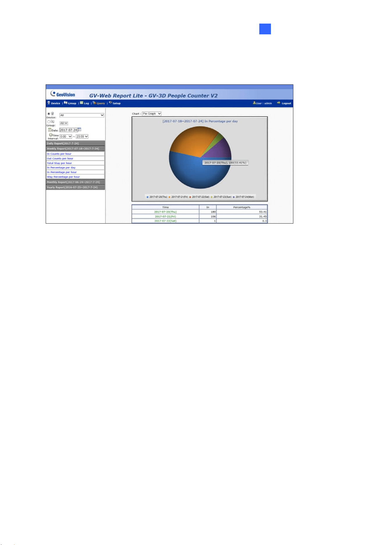
In Percentage per day: The daily percentage of people entered for the week.
In Percentage per hour: The hourly percentage of people entered for the week.
Stay Percentage per hour: The hourly percentage of people remaining for the week.
The Web Interface
29
3
The following figure is an example of the In Percentage per day option. The value
2017-07-20 (Thu), 180 (53.41%) indicates the total number of entered people on 2017/07/20
is 180. The number takes up 53.41 percent of the total people entered for the week.
Figure 3-33
[Monthly Report]
In Percentage per day: The daily percentage of people entered in the month.
In Percentage per hour: The hourly percentage of people entered in the month.
Stay Percentage per hour: The hourly percentage of people remaining in the month.
[Yearly Report]
In Percentage per month: The monthly percentage of people entered in the year.
Out Percentage per hour: The hourly percentage of people entered in the year.
Stay Percentage per hour: The hourly percentage of people remaining in the year.
30
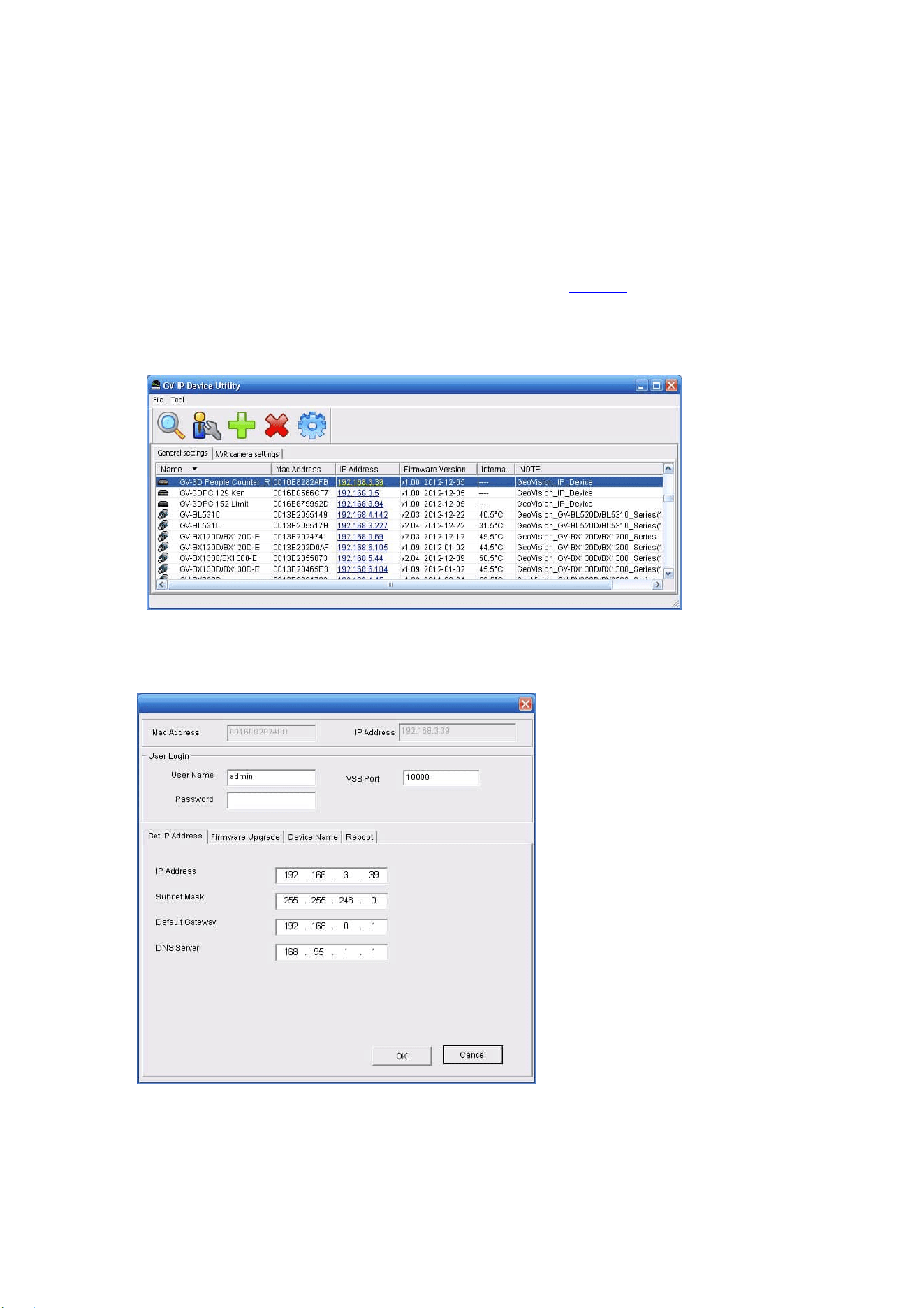
Chapter 4 GV-IP Device Utility
GV-IP Device Utility can detect GV-3D People Counter V2 in the LAN and allows you to set
the IP address of the device, upgrade firmware and reset the device.
1. Download and install the GV-IP Device Utility from our website
.
2. Double-click the GV-IP Device Utility created on your desktop. This dialog box appears
and automatically searches for the device under LAN.
Figure 4-1
3. Double-click a device. This dialog box appears.
Figure 4-2

GV-IP Device Utility
31
4
4. Click the following tabs to access these settings:
Set IP Address: Type the IP address, subnet mask, default gateway and DNS
server of the device.
Firmware Upgrade: To upgrade the firmware, click Browse to specify the path of
the firmware file and click Upgrade to proceed. You can select Upgrade all
devices to upgrade all devices with the same username and password.
Device Name: Rename the device.
Reboot: Reboot the device.
Load Default: Restore the device back to its factory default settings.
32
Appendix
Optimal Installation
To increase the accuracy of people counting results, be sure to install the GV-3D People
Counter V2 with the correct lighting conditions and avoid placing IR LED nearby. The
recommended installation height for GV-3D People Counter V2 is between 1.8 – 4 meters (5.91
– 13.12 feet).
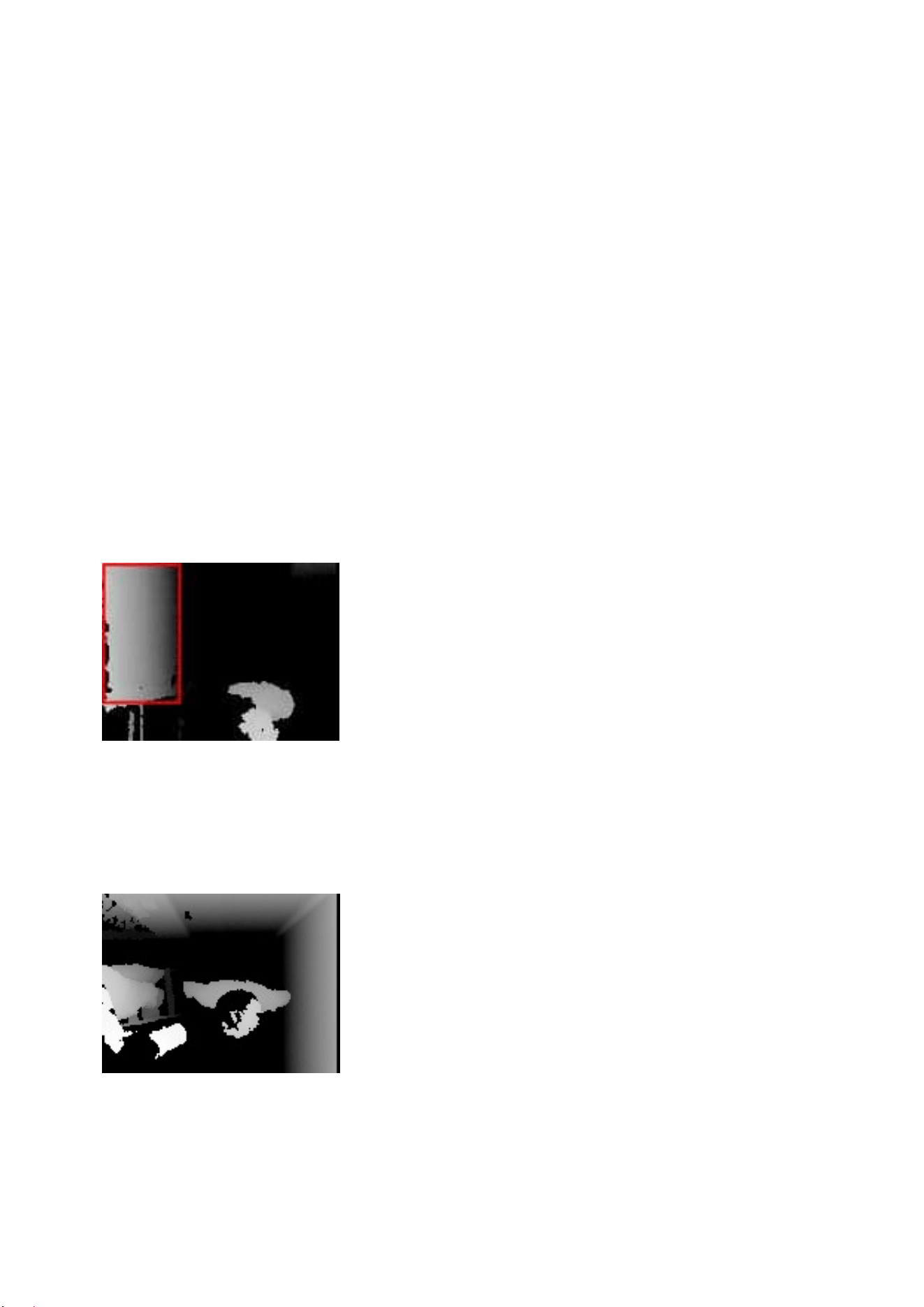
Avoid Direct Sunlight
Direct sunlight on the detection area may show up as a white region on the live view and
interferes with people counting results.
Avoid IR LED
IR LED from the left of the view interferes with the IR sensor of the GV-3D People Counter V2
and causes part of the person’s head to appear dark.
Appendix
33
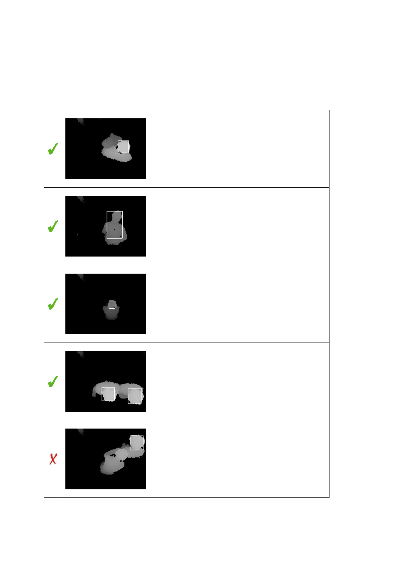
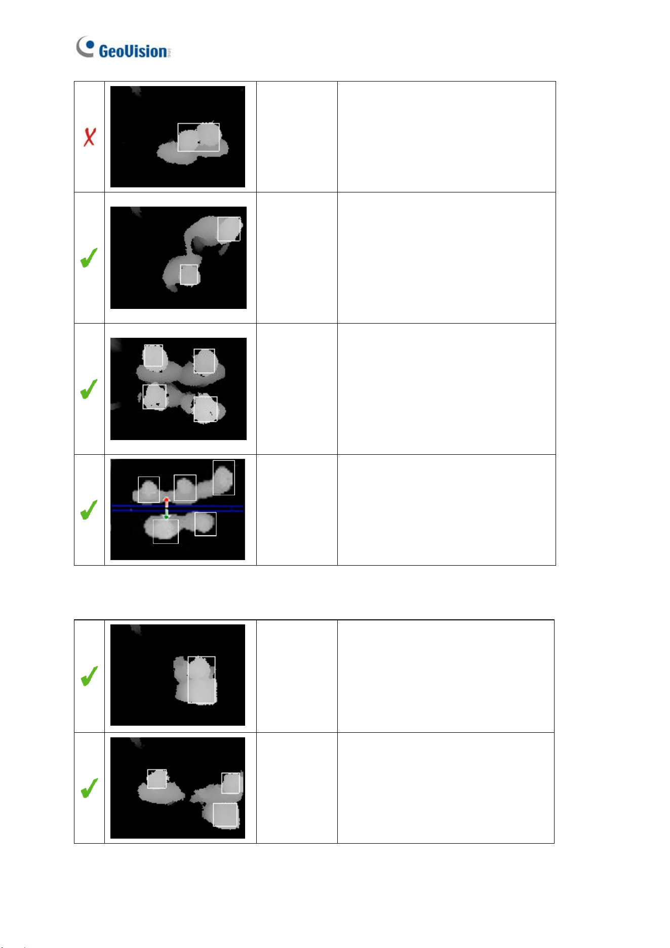
Detection Limitations
There are situations that may cause GV-3D People Counter V2 to falsely detect the number of
people. Below are examples of situations that may or may not result in false detection.
Actual: 1
Counted: 1
Standing upright
Actual: 1
Counted: 1
Leaning forward
Actual: 1
Counted: 1
Squatting down
Actual: 2
Counted: 2
Shoulder to shoulder
Actual: 2
Counted: 1
Head leaning on shoulder
34
Actual: 2
Counted: 1
Head to head
Actual: 2
Counted: 2
One hand on shoulder
Actual: 4
Counted: 4
Four people
Actual: 5
Counted: 5
Five People
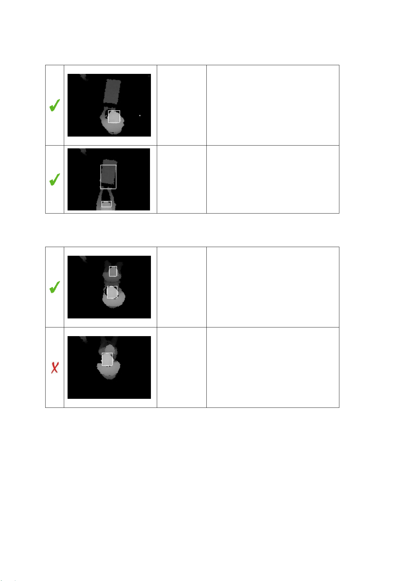
Carrying a large backpack:
Actual: 1
Counted: 1
Backpack in close contact with the
person’s head.
Actual: 2
Counted: 2
Backpack at a distance from the
person’s head.
Appendix
35
Pushing a cart:
Actual: 1
Counted: 1
Cart close to the person’s body.
Actual: 1
Counted: 1
Cart away from the person’s body.
Tip: Set a minimum detection height
that is higher than the cart to avoid
false detection.
Pushing a wheelchair:
Actual: 2
Counted: 2
The person pushing the wheelchair is
standing upright.
Actual: 2
Counted: 1
The person pushing the wheelchair
leans over and overlaps with the
wheelchair user.